1
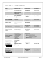
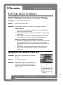
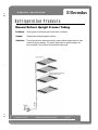
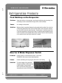
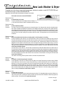
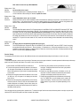
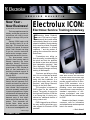
H O M E
P R O D U C T S
S E R V I C E
New Year New Business!
by John Carroll, EHP National Service Manager
The home appliance service
industry, and the way your service
technicians will need to work,
is about to change. Will you be
ready?
January 2004 begins with
new housing starts at an all
time high. The trend has been
building, so to speak, for several
years - and it means one thing
to you as a service technician
and a service company owner increased demand for service.
The phenomenal recent
growth in new housing starts is
already impacting the home
appliance industry. Electrolux
Home Products posted a record
growth year in 2003. We plan to
build on that performance by
providing increased support to
our independent service base
through 2004.
In analyzing service industry
trends, we see several emerging
factors that will separate successful servicers from others in
an ever more competitive business climate. New consumers
are more upwardly mobile than
in previous generations. Higher
end business will expand among
new homeowners - and they will
demand more of their appliances and of their service companies. Their demands will
include faster, better service
from technicians - requiring them
to be more knowledgeable and
B U L L E T I N
Electrolux ICON:
Electrolux Service Training Underway
lectrolux Home Products’
new ICON series of appliances will be in retail outlets
nationwide by March 1st, a month
ahead of schedule. Service training
for the new line of sleek, European
designed appliances is already
underway – and the product is
getting rave reviews from service
technicians.
E
“Technicians are telling us
that the quality is outstanding for
the price and that the products
are easier to tear down and repair
than competitive products,” said
Dino Neokratis, EHP Regional
Service Quality Manager currently
training in Minneapolis.
“Servicers are telling me they
think it is one of the best products
we have ever built. I am also
being told that installation is a
great deal easier than on other
products,” said Robert Giannetti,
training in the North East.
The reception is important to
EHP’s plans for the new model
launch. The quality of service for
the high-end Electrolux ICON line
is so strong that it is being considered an additional feature of
every product sold.
EHP’s biggest focus will be on
the way service technicians provide support for Electrolux ICON
products.
“We are asking servicers to
wear shoe covers, and use mats
to protect floors and counter tops
– and do everything they can to
provide superior service to Electrolux ICON consumers. This is
typical of service technicians in the
plumbing, HVAC and telephone
industries and is now becoming a
standard expectation of consumers everywhere” said John
Carroll, National Service Manager
for EHP.
Based on the March 1st date,
consumer calls for information
and related issues can be expected
later in the month.
— Mark Newell
continued on page 2
VOLUME 24 / ISSUE 1
JANUARY 2004
Service Bench ‘Report Card’ Feature
Enables More Intuitive Dispatch Decisions
O
n January 19th, Service Bench
announced new ‘Report Card’
features that enable manufacturers to dispatch servicers
based on specific service ratings.
Report Card, part of the Performance Center solution, gives
manufacturers detailed analyses
about the performance of their
service partners based on such key
factors as quality, delivery and
cost, incorporating direct feedback
from consumer surveys. The newest
features tie these report cards
together with DispatchCenter,
which enables automated service
scheduling and dispatch via the
Service Bench website.
Servicers that are ranked
highest can now be given first
access to service calls, ensuring
that the consumer is getting the
best repair experience possible. In
addition, the manufacturer can
better control costs and identify
important trends to help reduce
error, more effectively manage
parts supplies and identify potential
problem areas earlier in the process.
“Our goal in tying together
Report Card’s functionality with
the DispatchCenter solution is to
give manufacturers direct access
to key performance data that is
integral to a healthy services supply
chain and long-term customer
relationship,” said Michael Dering,
President and CEO of Service
Bench. “Sometimes a service
technician is the only face a customer
has to put with the manufacturer,
and these newest features help
ensure that the relationship is positive and intact, while strengthening
the entire service experience.”
“Service Bench has revolutionized the way that EHP manages its
servicer business, by enabling us
to deliver fast, responsive support
to our service companies and our
consumers,” Mark Newell, Head
of Communications for EHP Consumer Services, said. “These
newest Report Card features from
Service Bench help EHP ensure
the best possible service.”
2003 Service Manuals Available!
The following service manuals are now available
through your authorized parts distributor:
Part Number
5995393138
5995393146
5995377099
5995381885
5995383824
5995392593
5995391595
5995381117
5995303749
PAGE 2
Description
Tumble Action Washers w/ Electronic Controls
27" Dryers - Gas and Elec. Models w/ Electronic Controls
Top Load Washers - 2.7 and 3.0 Cu. Ft. Tubs
27" Laundry Centers - Gas and Electric
Product Information and Technical Guide:
SxS and Top Mount Refrigerators April 2002 - Dec. 2002
Product Information and Technical Guide:
SxS and Top Mount Refrigerators Jan. 2003 - June 2003
Product Information and Technical Guide:
2000 Room Air Conditioners
All Brands, All Products - 5-year set, 1998 through 2002
All Brands, All Products - 5-year set, 1993 through 1997
JANUARY 2004 SERVICE BULLETIN
‘New Year-New Business’ cont’d
adept in the soft skills. Consumers
will expect increasing levels of professional treatment from service
companies including quickly scheduled service calls to rapid updates
on changing appointments.
You are already well aware that
appliances have changed dramatically
over the past few years. Technical
sophistication means that more
appliances will be serviced by analyzing their on-board software rather than reaching for a wrench.
Appliance technology in the future
will require that service be performed
by technically adept servicers who
have access to live Internet and
wireless support.
The future opportunities for growth
of your service company, or your
career as a service technician, will
depend upon how you meet this new
challenge. To help you meet this
challenge, Electrolux will produce
new distance learning training materials and conduct over 400 training
meetings in 2004. There will also be
a new line of service accessories
with the Electrolux brand - everything
from patches to floor mats, caps to
shoe covers. These accessories will
improve the image of any company
servicing Electrolux Home Products
appliances.
On behalf of Electrolux, I would like
to thank each and every servicer for
their continued commitment to providing excellent consumer service to
Electrolux Home Products consumers.
EHP to Close Greenville Factory
Electrolux Home Products – North America
announced that it will discontinue production of
refrigerators at the Greenville, Michigan factory.
Production at Greenville will continue into 2005.
The 18 cu. ft. refrigerators currently manufactured in Greenville will be relocated to the
refrigerator factory in Anderson, SC. The remaining production will move to a new factory that will
be built in Mexico.
VOLUME 24, ISSUE 1
ELECTROLUX PHONE
NUMBERS
Name
Reason For Call
Phone Number
Fax Number
Customer Assistance
Center
Any Consumer Issue
706-860-4110
706-651-7135
Credit Department
Balance on Account
Need Invoice
614-825-0849
614-781-9312
Damage Claim Center
Return Authorization
Damage Claims
Damage Allowances
800-456-4669
(Option 1)
706-651-7715
Dealer / Distributor
Allowances
800-456-4669
(Option 2)
706-651-7054
National Locator
Parts, Service, Dealer,
Manuals
800-444-4944
Parts Department
Parts Questions
800-599-7569
(Option 2)
706-869-9096
706-228-4598
Product Specialist
(DDPS)
Product Exchange
800-456-4669
(Option 2)
706-651-7135
Servicer Assistance
Center (SAC)
Wiring Diagram
Technical Feedback
Territory Manager
Pay Increase
Technical
Specifications
Service Contract
NOTE: This information
is also available
by logging onto
ServiceBench.com
or Frigidaire.com
Contact Status
Number
Type
Model/Serial Number
Expiration Date
Full Coverage
Deductible
Warranty
NOTE: This information
is also available
by logging onto
ServiceBench.com
VOLUME 24, ISSUE 1
888-842-3660
option 1 warranty administration
option 2 for refrigerators, freezers,
air conditioners or dehumidifiers
option 3 for cooking
option 4 for laundry or dishwashers
888-842-3660
(Option 1)
706-651-7735
888-842-3660
(Option 1)
706-651-7735
JANUARY 2004 SERVICE BULLETIN
PAGE 3
SERVICE
SOLUTIONS
Finish Flaking From Rust on Freezer Tubing
Problem: The finish on freezer tubing flakes off.
Cause:
Rust and surface contamination.
Solution: Refrigerant tubing (anywhere in the freezer) may be cleaned and repainted.
Prepare the surface.
1. Use steel wool, a brass brush or sandpaper to clean off rust deposits, flaking
finish and any surface contamination.
2. Clean the tubing with isopropyl alcohol and dry thoroughly. A fan may be used
to speed drying.
3. Allow the tubing to come to room temperature before applying paint. (Check
paint manufacturer's instructions for recommended temperature range.)
Apply the paint following the paint manufacturer's instructions.
1. If the paint is to be applied inside the cabinet, use a brush-on paint, not a spray
paint. Rust-Oleum® #7715 Aluminum Industrial Enamel passed Electrolux
Home Products freezer division's Crosscut Adhesion and Taste and Odor Test
Requirements.
2. If the tubing is in the machine compartment, apply a rust-inhibiting paint. A
brush-on paint is recommended but a spray paint may be used in a wellventilated area.
Upright Freezer ‘Basket Track Kit’
Problem: Basket tracks in upright freezers pull-out from the
side walls.
Cause:
Too much weight in basket.
Solution: Install basket track repair kit (PN 216836700). The
kit includes two (2) stainless steel reinforcement
plates, six (6) insertion nuts, eight (8) screws and
instruction sheet.
PAGE 4
JANUARY 2004 SERVICE BULLETIN
VOLUME 24, ISSUE 1
SERVICE
SOLUTIONS
Manual Defrost Upright Freezer Tubing
Problem:
Shelving repair or replacement due to leaks and/or a restriction.
Cause:
Sealed system related refrigeration problems.
Solution:
The tubing used for the evaporator shelving in manual defrost upright freezers is made
of steel and may be soldered. The capillary tube/suction line (heat exchanger) may
also be soldered. Silver solder is recommended for these joints.
VOLUME 24, ISSUE 1
JANUARY 2004 SERVICE BULLETIN
PAGE 5
SERVICE
SOLUTIONS
External Condenser Kits
Problem: Internal condenser leak (high-side).
Cause:
Split tubing (leak) in condenser tubing.
Solution: External condenser kits are available for most freezer models and sizes. See the tables
below to order the correct kit. All kits come with the condenser, mounting hardware,
drier/filter and instructions.
Upright freezers
Size
Kit number
9 cu.ft.
5303304537
12 cu.ft.
5300123788
14 cu.ft.
5300123788
17 cu.ft.
5300083897
20 cu.ft.
5300083897
22 cu.ft.
5300083897
Chest freezers
Size
Kit number
4 cu.ft.
5300120779
5 cu.ft.
5300120779
7 cu.ft.
5300120780
9 cu.ft.
5300120781
13 cu.ft.
5303925238
15 cu.ft.
5303925238
18 cu.ft.
5303280307
20 cu.ft.
5303280307
23 cu.ft.
5300300173
25 cu.ft.
5300300173
PAGE 6
JANUARY 2004 SERVICE BULLETIN
VOLUME 24, ISSUE 1
SERVICE
SOLUTIONS
Frost Build-up on the Evaporator
Problem:
Heavy frost build-up on the evaporator, even though the defrost system is working. Also,
ice building on cube ice solenoid and/or auger motor, as well as damper.
Cause:
Air is leaking into the product.
Solution:
Make sure there is a good seal between the door gasket and the cabinet. Also, check the
fit of the door gasket into the door channel. Another place to look is the seal on the opening in the cabinet where the water lines enter. This opening is in the bottom right corner
of the food compartment, behind the light shield. The opening must be sealed all the way
around. It would be a recommended service practice to have a servicer check the opening
on any product you are servicing to make sure it is sealed.
Water line opening
Make sure the opening is sealed completely.
New Ice & Water Dispenser Switch
Problem:
Indicator sticking on electromechanical switch - part number
5304430836, used in some ice and water dispensers.
Cause:
Indicator was floating and not giving the customer the correct setting.
Solution:
The internal design of the switch was
changed by adding an additional spring
at each indicator to improve button
action and eliminate indicator float. The
new switch part number is 5304436275.
VOLUME 24, ISSUE 1
JANUARY 2004 SERVICE BULLETIN
PAGE 7
SERVICE
SOLUTIONS
Top Load & Laundry Center Washer Mandate!
Beginning January 1, 2004, the DOE (Department of Energy) has mandated that all clothes washers meet
a maximum energy usage rating.
A critical component to obtaining this rating is a 70/30 water valve. A 70/30 water valve sets the incoming
mixture of water at 70% cold and 30% hot when used on the warm water setting. However, this valve will
not affect water temperatures on models with an ATC (Automatic Temperature Control). ATC models have
a new control board with non-compliant water temperature settings.
On all super capacity model washers (3.0 ft³ wash basket), the pressure switch has been changed to lower
the water level.
Previous models:
High Water Level Setting
13.5 - 15.2 inches
Low Water Level Setting
5.5 - 7.8 inches
New models:
High Water Level Setting
10.8 - 13.0 inches
Low Water Level Setting
4.3 - 6.6 inches
Models affected are:
CWS3600AS1
FWS1233AS2
FWS1339AC0
FWS1339AC1
FWS1339ZDC0
FWS833AS2
GCET1031CS0
GCET1142CS0
GCGT1142CS0
GCGT1142CS1
GES831CS0
GLET1031CS0
GLET1142CS0
GLGT1031CS0
GLGT1031CS1
GLGT1142CS0
GLGT1142CS1
GLWS1233AQ2
GLWS1233AS2
GLWS1339CC0
GLWS1339CS0
GLWS1339CS1
GLWS1649AS4
GLWS1749AS4
GLWS1939AS1
GLWS1939CC0
GLWS1979AS3
GSWS9719AS2
GWS1339CS0
GWS1339CS1
GWS1749CS0
GWS833CS0
MWS833AS2
WARNING!
Any attempt to modify the pressure switch or replace it with an older style switch
is a violation of Federal Law and will void the warranty.
PAGE 8
JANUARY 2004 SERVICE BULLETIN
VOLUME 24, ISSUE 1
New Look Washer & Dryer
Frigidaire has introduced a new look laundry pair: electronic washer, model GLTF2070CS0 and
an electronic dryer, model GLE/GQ942CS0.
Diagnosis of the fault codes and function testing are as follows:
Fault codes for electronic washer GLTF2070CS0
Display shows: F 01
Indicates:
An internal fault in the control.
Correction:
Touch the Stop/Clear pad. If the display continues to display F 01
or if the code returns when the washer is restarted, replace the control.
Display shows: F 02
Indicates:
A water temperature problem.
Correction:
First check to see if the incoming water hoses are connected properly. If so, disconnect both wires from the water temperature sensor and measure the resistance of the sensor. If the reading is less than 3K or more than 163K, replace the sensor.
If the reading is between 3K and 163K, reconnect the wires to the sensor and unplug the small four pin plug from the control
board. Measure the resistance between pins 3 and 4 in the plug. If the reading is the same as the sensor reading, replace
the control board. If the meter reading is not the same as that at the sensor, the wiring between the control board and sensor
is defective.
Display shows: F 03
Indicates:
Water level problem caused by either no incoming water or the drain pump is not working.
Correction:
Touch the Stop/Clear pad to clear the F 03. Check the drum for water. If the drum has a normal fill of water, touch the
Drain/Spin pad and press the start pad. If the water does not pump out, remove the front access panel and measure the voltage drop across terminals of the drain pump. If the meter reads 120 VAC, the drain pump is defective or the drain hose is
plugged. If the meter reads zero, disconnect power, remove the large four pin plug (JX) and the eight pin plug (J11) from the
back of the control. Measure the resistance between pin 3 in the four pin plug and pin 3 of the eight pin plug. If the meter
reads open, the wires between the control board and the drain pump are defective. If the meter reads around 15 Ohms, the
control board should be replaced.
If the drum does not have water in it, start the washer in the Normal Cycle and select Warm Wash. If the washer does not
fill, make sure the faucets are turned on, unplug one of plugs from the water valve and measure the voltage drop across the
terminals in the plug. If the meter reads 120VAC, the water valve is defective. If the meter reads zero, measure for voltage from
each terminal in the plug to neutral. If the meter reads zero from each terminal, the pressure switch or the wiring to the pressure switch is defective. If the meter reads 120VAC from one terminal, the control board or the wiring from the valve to the
control board is defective.
If the washer is over filling, check the pressure switch or the tube to the pressure switch.
Display shows: F 04
Indicates:
The washer is not advancing through it increments.
Correction:
Touch Stop/Clear to clear the F 04. Select and start the washer in the Heavy Duty wash cycle with the Heavy Soil/Stain
Option deactivated. If the tub does not start turning while filling or within 30 seconds after the fill is completed, troubleshoot for a motor will not run problem. If the motor is running and the tub is filled, let the washer run for at least 6 minutes. Measure the voltage between pin one of the 8 pin connector (J11) and pin 7 of the 7 pin connector (J6). The voltage
should be below 50 VAC when the timer advances is off and line voltage when the timer advance is on. If the meter reading
does not switch between these two reading, the motor speed control is defective. If the meter reading switches between
these two reading, the electronic control board is defective.
Display shows: F 05
Indicates:
A problem with the key pad.
Correction:
Disconnect the keypad ribbon from the control and reconnect the ribbon. Try all keypad switches to see they all function correctly. If they do not, then try cleaning the end of the ribbon with a soft cotton cloth. Reinstall the ribbon and program the
washer to operate. If the code reoccurs, replace the touch pad.
continued on next page
VOLUME 24, ISSUE 1
JANUARY 2004 SERVICE BULLETIN
PAGE 9
(fault codes for electronic washer GLTF2070CS0 – continued)
Code:
Indicates:
Correction:
ddo
Drawer reed switch is not closed.
Make sure the drawer is closed. If the drawer is closed, check that the magnet in the drawer is in the correct position. If the magnet
is in the correct position, check the reed switch.
Code:
Indicates:
Correction:
dr
Door switch is not closed.
Check that the door is closed and the door catch is not broken. If so, replace the door lock assembly.
Function Testing:
Test programs are built into the control to allow different functions to be activated without waiting for the function to occur in the cycle.
Membrane Test:
To activate the membrane test, remove power from the washer. Then reconnect power to the washer and within 10 seconds press and hold the
temps and the stop pads for at least 2 seconds, then release. The control is now in the test function.
1. Starting with the Cycles pad, touch each pad and see that the appropriate LED's or the appropriate display symbol illuminates.
Note: When Delay pad is touched, the complete display illuminates.
Test Program:
To start the test program, remove power from the washer. Then reconnect power to the washer and within 10 seconds press and hold the temp
and the stop pads for at least 2 seconds, then release. The control is now in the test function.
1. Press the stop pad and then the start pad. (H) will appear in
the display and the hot water valve circuit is activated.
2. Retouch the start pad and the test will advance to the cold
water test. (C) will appear in the display and the cold water
valve circuit is activated.
3. Retouch the start pad and the test will advance to the warm
water test. (HC) will appear in the display and both the hot
water valve circuit and the cold water valve circuit are activated.
4. Retouch the start pad and the test will advance to the bleach
dispenser test. (bL) will appear in the display and the bleach
solenoid circuit is activated.
5. Retouch the start pad and the test will advance to the fabric
softener test. (FA) will appear in the display and the fabric softener solenoid circuit is activated.
6. Retouch the start pad and the test will advance and release the
door solenoid. (dr) will appear in the display and the door can
be opened.
7. Retouch the start pad and the test will advance to the agitation
and warm water test. (HC) will appear in the display and the
drum will fill with warm water and agitate.
8. Retouch the start pad and the test will advance to the final spin
test. (FS) will appear in the display and in about 30 second the
washer will go into final spin.
Press the Stop pad, then the Start pad to repeat the test. To remove the washer from the test mode, disconnect power from the washer or press
and hold the stop & the cycles pads for at least 2 seconds, then release.
Demo Mode:
For sales demonstration of the board LED's without function of the washer, remove power from the washer. Reconnect power to the washer and
within 10 seconds, hold the stop/clear pad for at least 6 seconds. To remove the washer from the test mode, disconnect power from the washer
or press and hold the stop and the cycles pads for at least 2 seconds, then release.
PAGE 10
JANUARY 2004 SERVICE BULLETIN
VOLUME 24, ISSUE 1
Fault codes for electronic dryer GLE/GQ942CS0
Display shows: F 01
Indicates:
An internal fault in the control.
Correction:
Touch the Stop/Clear pad. If the display continues to display F 01
or if the code returns when the dryer is restarted, replace the control.
Display shows: F 02
Indicates:
Control temperature sensor open or shorted.
Correction:
Remove the wires from the control temperature sensor and measure the resistance of the sensor. If the meter does not read
50,000 Ohms +/- 10% replace the sensor. If the meter reading is within 10% of 50,000 Ohms, check the wiring between the
electronic control board and the sensor. If the wiring is good, replace the electronic control board.
Display shows: F 03
Indicates:
No heat
Correction:
Touch the Stop/Clear pad to clear the F 03. Program the dryer for a NORMAL CYCLE with HIGH HEAT and touch START. Measure the voltage drop across the terminals of relay RL 2 on the electronic control board. If the meter reads 240 VAC on electric models or 120 VAC on gas models, replace the electronic control board. If the meter reads zero, remove power from the
dryer and disconnect the black wire electric models and orange wire gas models from the relay. Reconnect power and measure
the voltage drop between the red wire on the relay RL 2 to neutral. If the meter reads zero, the wire between the incoming line
and relay RL 2 is open. If the meter reads 120 VAC, check the rest of the heating circuit as described in the trouble shooting
section.
Display shows: F 04
Indicates:
The drying time has exceeded the program time for that cycle.
Correction:
Touch the Stop/Clear pad. Program the dryer for a NORMAL CYCLE with HIGH HEAT and touch START. Check for anything
that would extend the dry time such as: 1. Dryer not heating. 2. Restricted vent. 3. Blower fan blade broken or loose. 4. Dryer
installed in a closet with a solid door. 5. Bad connection in sensor bar circuit or dirty sensor bars. If the dryer operates normally
but the F 04 code returns, replace the control.
Function Testing:
Test programs are built into the control to allow different functions to be activated without waiting for the function to occur in the cycle.
Test Program:
To start the test program, remove power from the dryer. Reconnect power to the dryer and within 10 seconds press and hold the temps and the stop
pads for at least 2 seconds, then release. The control is now in the test function.
1. After activation, the PRESS SAVER icon should be on.
2. Touch the start pad and the test will advance to the heat test.
(H) will appear in the display, the drive motor will run and the
electric heating element or gas burner will operate depending
on the model.
3. Retouch the start pad and the test will advance to the no heat
(air fluff) test. (AF) will appear in the display and the drive
motor will run.
4. Retouch the start pad and the test will advance to the auto dry
moisture counts test. The AUTO DRY icon will illuminate and a
number will appear in the display. Open the door, place your
hand against the sensor bars and the amount of the number in
the display should go down.
5. Retouch the start pad and the test will advance to the membrane test. The display will be blank. Press each cycle pad and
the LED's should light.
6. Retouch the start pad and the test will advance to the cool
down test. The COOL DOWN icon will illuminate and a number
will appear in the display and the drive motor will run.
7. Retouch the start pad and the test will advance to the timed dry
test. The TIMED DRY icon will illuminate and a number will
appear in the display. The drive motor will run and the electric
heating element or gas burner will operate depending on the
model.
Press the stop pad, then the start pad to repeat the test. To remove the dryer from the test mode, disconnect power to the dryer or press and
hold the STOP and CYCLES pads for at least 2 seconds, then release.
VOLUME 24, ISSUE 1
JANUARY 2004 SERVICE BULLETIN
PAGE 11
Electrolux Home Products
Has All the
Replacement Ignitors
You’ll Ever Need!
That’s right, just 3 universal ignitors
could lower your inventory,
save you money
and give you
peace of mind!
Ignitor #5303935066
replaces: GR411, GR412, IGN-0,
IGN-5, IGN-8, 41-205, 41-209
Ignitor #5303935067
replaces: GR409, GR410,
IGN-2, 41-202, 41-208
These 3 versatile, durable,
Ignitor #5303935068
universal ignitors fit almost all
replaces: GR407, IGN-1, IGN-7,
41-201, 41-207, 1482-224
3.2 to 3.6 amp gas ranges. Electrolux ignitors
lower your inventory, save you money and lower costly call backs!
Call your Authorized Parts Distributor for more information.
Electrolux Home Products, NA
250 Bobby Jones Expressway, Augusta, Georgia 30907
www.frigidaire.com