1
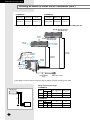
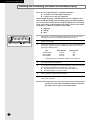
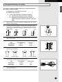
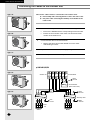
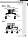
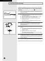
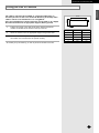
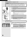
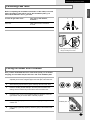
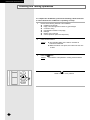
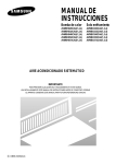
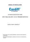
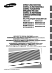
Indoor unit
Outdoor unit
AM14B1(B2)E07
AM18B1(B2)E09
AM20B1(B2)E06
AM20B1(B2)E09
AM26B1(B2)E07
AM26B1(B2)E12
AM18B1(B2)B09
AM26B1(B2)B13
MC18AC2-09
MC19AC2-07
MC19AC2-12
MC24AC2-12
MC26AC2-07
MC26AC2-12
UM14B1(B2)E2
UM18B1(B2)E2
ENGLISH
ESPAÑOL
FRANÇAIS
INSTALLATION MANUAL
MANUAL DE INSTALACIÓN
MANUEL D’INSTALLATION
MANUALE D’INSTALLZIONE
MANUAL DE INSTALAÇÃO
INSTALLATIONS-HANDBUCH
E°XEIPI¢IOE°KATA™TA™H™
àçëíêìäñàü èé ìëíÄçéÇäÖ
UM26B1(B2)E3
UM18B1(B2)B2
UM26B1(B2)B2
MC18AC2X
ITALIANO
UM20B1(B2)E3
RUSSIAN
MULTI-SPLIT TYPE ROOM AIR CONDITIONER ( Cool )
ACONDICIONADOR DE AIRE DOMÉSTICO SISTEMA MULTI SPLIT ( Refrigeración )
CLIMATISEUR DE TYPE MULTIPLE ( Refroidissement )
CONDIZIONATORE D’ARIA PER PIÙ AMBIENTI AD UNITÀ SEPARATE ( Raffreddamento )
AR CONDICIONADO MULTI SPLIT ( Refrigeração )
RAUMKLIMAGERÄT IN MEHRFACH GETEILTER AUSFÜHRUNG ( Kühlen )
¶O§Y¢IAIPOYMENO K§IMATI™TIKO ¢øMATIOY( æ‡Í˘ )
äéåçÄíçõâ ÇéáÑìòçõâ äéçÑàñàéçÖê íàèÄ åìãúíà-ëèãàí ( éı·ʉÂÌË )
DEUTSCH
MC26AC2X
E§§HNIKA
MC24AC2X
PORTUGUÉS
MC19AC2X
E S F I P D G R DB98-03916A(2)
Which model air conditioner have you purchased?
This Installation Manual is made for various models.
Make sure what model you purchased then install your air conditioner as your type.
A Type
B Type
C Type
D Type
E Type
AM14B1(B2)E07
AM18B1(B2)E09
AM20B1(B2)E06
AM26B1(B2)B13
AM26B1(B2)E07
AM18B1(B2)B09
AM20B1(B2)E09
MC24AC2-12
AM26B1(B2)E12
MC18AC2-09
MC26AC2-07
MC19AC2-07
MC26AC2-12
MC19AC2-12
E-2
ENGLISH
Contents
◆ PREPARING THE INSTALLATION
■
Deciding on Where to Install the Air Conditioner ..........................................
■
Air Conditioner and Accessories ...................................................................
4
8
◆ INSTALLING THE INDOOR UNIT
■
Fixing the Installation Plate ...........................................................................
■
Purging the Unit.............................................................................................
■
Connecting the Assembly Cable ...................................................................
■
Installing and Connecting the Indoor Unit Drain Hose..................................
■
Installing and Connecting the Indoor Unit Assembly Piping .........................
■
Cutting/Extending the Piping ........................................................................
11
12
12
13
14
15
◆ INSTALLING THE OUTDOOR UNIT
■
Connecting the Cables to the Outdoor Unit ..................................................
■
Checking Correct Earthing ............................................................................
■
Fixing the Unit in Position ............................................................................
16
18
19
◆ COMPLETING THE INSTALLATION
■
Connecting Up and Purging the Circuit.........................................................
■
Adding Refrigerant ........................................................................................
■
Performing Leak Tests...................................................................................
■
Placing the Indoor Unit in Position ................................................................
■
Checking and Testing Operations .................................................................
■
Explaining Operations to the Owner .............................................................
20
20
21
21
22
23
◆ TECHNICAL SPECIFICATIONS
E-3
PREPARING THE INSTALLATION
Deciding on Where to Install the Air Conditioner
When deciding on the location of the air conditioner with the owner, the following restrictions
must be taken into account.
General
Do NOT install the air conditioner in a location where it will come into contact with the following elements:
◆ Combustible gases
◆ Saline air
◆ Machine oil
◆ Sulphide gas
◆ Special environmental conditions
If you must install the unit in such conditions, first consult your dealer.
Indoor Unit
◆ There must be no obstacles near the air inlet and outlet.
◆ Install the indoor unit on a surface that can support its weight.
◆ Choose a position that enables the piping and cables to be easily connected to the outdoor unit and the
recommended length of 5 metres to be respected.
◆ Leave enough clearance beneath the indoor unit to enable the filters to be removed without hindrance.
◆ Maintain sufficient clearance around the indoor unit, as indicated in the diagram on the page opposite.
◆ Make sure that the water dripping from the drain hose runs away correctly and safely.
Outdoor Unit
◆ The outdoor unit must NEVER be placed on its side or upside down, as the compressor lubrication oil will run into the
cooling circuit and seriously damage the unit.
◆ Choose a location that is dry and sunny, but not exposed to direct sunlight or strong winds.
◆ Do not block any passageways or thoroughfares.
◆ Choose a location where the noise of the air conditioner when running and the discharged air do not disturb any
neighbours.
◆ Choose a position that enables the piping and cables to be easily connected to the indoor unit and the recommended
length of 5 metres to be respected.
◆ Install the outdoor unit on a flat, stable surface that can support its weight and does not generate any unnecessary
noise and vibration.
◆ Position the outdoor unit so that the air flow is directed towards the outside, as indicated by the arrows on the top of
the unit.
◆ Maintain sufficient clearance around the outdoor unit, as indicated in the diagram on the page opposite.
◆ If the outdoor unit is installed at a height, ensure that its base is firmly fixed in position; the maximum height
is 7 metres.
◆ Make sure that the water dripping from the drain hose runs away correctly and safely.
CAUTION
◆ You have just purchased a multi-split type room air conditioner and it
has been installed by your installation specialist.
◆ This device must be installed according to the national electrical rules.
E-4
ENGLISH
PREPARING THE INSTALLATION
◗ 14000Btu/h
Indoor unit
Outdoor unit
AM14B1(B2)E07 UM14B1(B2)E2
Power supply
Ø, V, Hz
1,220-240~,50
Respect the clearances and maximum lengths indicated in the diagram below when installing the unit.
B-unit
7000 Btu/h(2.05kW)
20 mm
or more
A-unit
7000 Btu/h(2.05kW)
100 mm
or more
160 mm
or more
600 mm
minimum
A
(15 metres
maximum)
300 mm
minimum
B
(7 metres
maximum)
300 mm
minimum
600 mm
minimum
A
B
Circuit breaker
(20A)
Main power switch
❋ The designs of the unit and the connection valve are subject to change according to the model.
Piping length and the height
Pipe size
Liquid GAS
A-unit 1/4" 3/8"
B-unit 1/4" 3/8"
Unit
MAX. piping length
A
15 m
15 m
MAX. height
B
7m
7m
INDOOR UNIT
A
B
OUTDOOR UNIT
E-5
PREPARING THE INSTALLATION
Deciding on Where to Install the Air Conditioner (cont.)
◗ 19000Btu/h
◗ 18000Btu/h
Indoor unit
Power supply
Ø, V, Hz
Outdoor unit
AM18B1(B2)E09 UM18B1(B2)E2
MC18AC2-09
MC18AC2X
1,220-240~, 50
AM18B1(B2)B09 UM18B1(B2)B2
1,220~, 60
Indoor unit
Outdoor unit
Power supply
Ø, V, Hz
MC19AC2-07
MC19AC2-12
MC19AC2X
1,220-240~, 50
Respect the clearances and maximum lengths indicated in the diagram below when installing the unit.
B-unit 9000 Btu/h(2.6kW)/
12000 Btu/h(3.5kW)
20 mm
or more
A-unit 7000 Btu/h(2.05kW)/
9000 Btu/h(2.6kW)
100 mm
or more
160 mm
or more
600 mm
minimum
B
(7 metres
maximum)
A
(15 metres
maximum)
300 mm
minimum
300 mm
minimum
600 mm
minimum
A
B
Circuit breaker
(20A)
Main power switch
❋ The designs of the unit and the connection valve are subject to change according to the model.
Piping length and the height
A
B
OUTDOOR UNIT
E-6
Pipe size
Liquid GAS
A-unit 1/4" 3/8"
B-unit 1/4" 3/8"
Unit
INDOOR UNIT
MAX. piping length
A
15 m
15 m
MAX. height
B
7m
7m
ENGLISH
PREPARING THE INSTALLATION
◗ 20000Btu/h
Indoor unit
Outdoor unit
Power supply
Ø, V, Hz
AM20B1(B2)E06
UM20B1(B2)E3 1,220-240~, 50
AM20B1(B2)E09
Respect the clearances and maximum lengths indicated in the diagram below when installing the unit.
C-unit
5400 Btu/h(1.58kW)
B-unit
5400 Btu/h(1.58kW)
20 mm
or more
A-unit
9000 Btu/h(2.6kW)
100 mm
or more
160 mm
or more
B
(7 metres
maximum)
600 mm
minimum
A
(15 metres
maximum)
300 mm
minimum
300 mm
minimum
A
600 mm
minimum
B
C
Circuit breaker
(20A)
Main power switch
❋ The designs of the unit and the connection valve are subject to change according to the model.
Piping length and the height
Pipe size
Liquid GAS
A-unit 1/4" 3/8"
B-unit 1/4" 3/8"
C-unit 1/4" 3/8"
Unit
MAX. piping length
A
15 m
15 m
15 m
MAX. height
B
7m
7m
7m
INDOOR UNIT
A
B
OUTDOOR UNIT
E-7
PREPARING THE INSTALLATION
Deciding on Where to Install the Air Conditioner (cont.)
◗ 24000Btu/h
◗ 26000Btu/h
Indoor unit
Outdoor unit
Power supply
Ø, V, Hz
MC24AC2-12
MC24AC2X
1,220-240~, 50
Indoor unit
Outdoor unit
AM26B1(B2)B13 UM26B1(B2)B2
Power supply
Ø, V, Hz
1,220~, 60
Respect the clearances and maximum lengths indicated in the diagram below when installing the unit.
B-unit 12000 Btu/h(3.5kW)/
13000 Btu/h(3.8kW)
20 mm
or more
A-unit 12000 Btu/h(3.5kW)/
13000 Btu/h(3.8kW)
100 mm
or more
160 mm
or more
B
(7 metres
maximum)
600 mm
minimum
A
(15 metres
maximum)
300 mm
minimum
300 mm
minimum
600 mm
minimum
A
B
Circuit breaker
(20A)
Main power switch
❋ The designs of the unit and the connection valve are subject to change according to the model.
Piping length and the height
◗ 24000Btu/h
INDOOR UNIT
Pipe size
Liquid GAS
A-unit 1/4" 3/8"
B-unit 1/4" 3/8"
Unit
A
MAX. height
B
7m
7m
MAX. piping length
A
15 m
15 m
MAX. height
B
7m
7m
◗ 26000Btu/h
B
Unit
OUTDOOR UNIT
E-8
MAX. piping length
A
15 m
15 m
A-unit
B-unit
Pipe size
Liquid GAS
1/4"
1/4"
1/2"
1/2"
ENGLISH
PREPARING THE INSTALLATION
◗ 26000Btu/h
Indoor unit
Outdoor unit
Power supply
Ø, V, Hz
C-unit
7000 Btu/h(2.05kW)
AM26B1(B2)E07 UM26B1(B2)E3
AM26B1(B2)E12
1,220-240~, 50
MC26AC2-07
MC26AC2X
MC26AC2-12
B-unit
7000 Btu/h(2.05kW)
Respect the clearances and maximum
lengths indicated in the diagram below
when installing the unit.
A-unit
12000 Btu/h(3.5kW)
20 mm
or more
100 mm
or more
160 mm
or more
B
(7metres
maximum)
600 mm
minimum
A
(15 metres
maximum)
300 mm
minimum
300 mm
minimum
600 mm
minimum
A
B
C
Circuit breaker
(20A)
Main power switch
❋ The designs of the unit and the connection valve are subject to change according to the model.
Piping length and the height
◗ AM26B1(B2)E07, AM26B1(B2)E12
Pipe size
Liquid GAS
A-unit 1/4" 1/2"
B-unit 1/4" 3/8"
C-unit 1/4" 3/8"
Unit
MAX. piping length
A
15 m
15 m
15 m
MAX. height
B
7m
7m
7m
INDOOR UNIT
A
B
◗ MC26AC2-07, MC26AC2-12
Unit
A-unit
B-unit
C-unit
Pipe size
Liquid GAS
1/4"
1/4"
1/4"
3/8"
3/8"
3/8"
MAX. piping length
A
15 m
15 m
15 m
MAX. height
B
7m
7m
7m
OUTDOOR UNIT
E-9
PREPARING THE INSTALLATION
Air Conditioner and Accessories
The following accessories are supplied with the air conditioner.
Accessories in the Indoor Unit Case
Installation Plate
Remote Control
Batteries for
Remote Control
Accessories in the Outdoor Unit Case
Owner’s Instruction
Booklet
Rubber Leg
Installation Manual
MANUAL
CION
INSTALLATION
MANUAL DE INSTALA
LAZIONE
MANUALE D’INSTAL O
MANUAL DE INSTALA
LATION
MANUEL D’INSTAL
ANDBUCH
INSTALLATIONS-H
TIONS
OWNER’S INSTRUC CIONES
MANUAL DE INSTRUC
L’USO
ISTRUZIONI PER ˝ES
MANUAL DE INSTRU
TION
MANUEL D’UTILISA
EISUNG
GEBRAUCHSANW
Air Conditioner
Splut-type Room stico sistema Split
dom
ad unit Separate
Aire acondicionado
d’aria per ambienti
Condizionatorede ar condicionado tipo Split
Aparelho
type s par
Climatiseur de
Geteilte raumklimaanlage
Air Conditioner
Splut-type Room stico sistema Split
dom
ad unit Separate
Aire acondicionado
d’aria per ambienti
Condizionatorede ar condicionado tipo Split
Aparelho
type s par
Climatiseur de
Geteilte raumklimaanlage
3-wire
Power Cable
➢
Flare Nuts, 6.35mm
outer pipe diameter
4-wire Assembly
Cable
Flare Nuts, 12.70mm
outer pipe diameter
The 3-wire power cable and the 4-wire assembly cable are optional. If these cables are not
supplied, use the standard cable approved by IEC standard.
The specification for cables
AWG
➢
Flare Nuts, 9.52mm
outer pipe diameter
Cross sectional area (mm2)
Three-wire power cable
14 or more
2.0 or more
Four-wire assemble cable
17 or more
1.0 or more
The flare nuts are only included when the air conditioner is supplied without the assembly
piping illustrated below.
The following connection accessories may be supplied, depending on the option. If they are not
supplied, it is recommended that you collect them together before starting to install the air
conditioner.
Assembly Piping,
Ø6.35mm by 5m
Pipe Clamps A
➢
E-10
Assembly Piping,
Ø9.52mm by 5m
Pipe Clamps B
Assembly Piping,
Ø12.70mm by 5m
M3.8 x 20 Screws
for Wood
PE T3 Foam Tube
Insulation
M4 x 16 Tapped
Screws
Vinyl Tape,
Width 50mm
Drain Hose,
length 2m
If these accessories are supplied, they are located in the accessory box.
Putty 100g
INSTALLING THE INDOOR UNIT
ENGLISH
Fixing the Installation Plate
Before fixing the installation plate to a wall or window frame, you
must determine the position of the 65 mm hole through which the
cable, piping and hose pass to connect the indoor unit up to the
outdoor unit. When facing the air conditioner in position on the wall,
the piping and cable can be connected from the:
◆ Right
◆ Left
◆ Rear (right or left)
Then follow Steps...
Wall
3.
Window frame
4 to 6.
Fix the installation plate to the wall in a manner appropriate to the weight
of the indoor unit.
➢ If you are mounting the plate on a concrete wall with anchor
bolts, the anchor bolts must not project by more than 20 mm.
4
Determine the positions of the wooden uprights to be attached to the
window frame.
5
Attach the wooden uprights to the window frame in a manner appropriate
to the weight of the indoor unit.
6
Using tapped screws, attach the installation plate to the wooden uprights,
as illustrated in the last figure opposite.
Pipe hole
(Ø65mm)
(Unit : mm)
252
275
30
3
If you are fixing the indoor unit to a...
Installation plate
30mm
2
Determine the position of the pipe and drain hose hole using the right
figure and drill the hole with an inner diameter of 65 mm so that it slants
slightly downwards.
60
1
90
140
410~730
(Unit : mm)
E-11
INSTALLING THE INDOOR UNIT
Purging the Unit
On delivery, the indoor unit is loaded with an inert gas. All this gas
must therefore be purged before connecting the assembly piping.
To purge the inert gas, proceed as follows.
Unscrew the caps at the end of each pipe.
Result: All inert gas escapes from the indoor unit.
➢
To prevent dirt or foreign objects from getting into the pipes
during installation, do NOT remove the caps completely
until you are ready to connect the piping.
Connecting the Assembly Cable
The outdoor unit is powered from the indoor unit via the assembly cable.
If the outdoor unit is more than five metres away from the indoor unit,
the cable must first be extended to a maximum of 15 metres.
1
Extend the assembly cable if necessary.
2
Open the front grille by pulling on the tabs on the lower right and left sides
of the indoor unit.
3
Remove the screw securing the connector cover.
4
Pass the assembly cable through the rear of the indoor unit and connect the
assembly cable such as figure.
Indoor
unit
➢ Each wire is labelled with the corresponding terminal number.
1 2
Outdoor 1
unit
2
3
E
3
1 2 3
(L) (N) COM
Earth terminal
E-12
Earth
terminal
5
Pass the other end of the cable through the 65 mm hole in the wall.
6
Replace the connector cover, carefully tightening the screw.
7
Close the front grille.
8
For further details on how to plug the other end of the assembly cable into
the outdoor unit, refer to pages 16~17.
E
E
INSTALLING THE INDOOR UNIT
ENGLISH
Installing and Connecting the Indoor Unit Drain Hose
Care must be taken when installing the drain hose for the indoor unit to ensure that any condensation
water is correctly drained outside. When passing the drain hose through the 65 mm hole drilled in the
wall, check that none of the following situations occur.
5 cm
less
The hose must
NOT slope
upwards.
The end of the drain
hose must NOT be
placed in water.
Do NOT bend the
hose in different
directions.
Keep a clearance of
at least 5 cm between
the end of the hose
and the ground.
Ditch
Do NOT place the
end of the drain hose
in a hollow.
To install the drain hose, proceed as follows.
1
If necessary, connect the 2-metre extension to the drain hose.
2
If you are using the extension, insulate the inside part of the extension
drain hose with a shield.
3
Pass the drain hose under the refrigerant piping, taking care to keep the
drain hose tight.
4
Pass the drain hose through the hole in the wall, making sure that it is
sloping downwards, as shown in the illustrations above.
➢
Shield
Drain hose
Extension drain hose
The hose will be fixed permanently into position once the
whole installation has been tested for gas leaks; refer to
page 21 for further details.
E-13
INSTALLING THE INDOOR UNIT
Installing and Connecting the Indoor Unit Assembly Piping
There are two refrigerant pipes of different diameters:
◆ A smaller one for the liquid refrigerant
◆ A larger one for the gas refrigerant
A short length of piping is already fitted to the air conditioner. You
must extend this piping using assembly piping (optionally supplied).
The connection procedure for the refrigerant piping varies according
to the exit position of the piping from the indoor unit, as seen when
facing the air conditioner in position on the wall:
◆ Right (A)
◆ Left (B)
◆ Rear
B
A
1
With a knife, cut out the appropriate knock-out piece on the rear of the
indoor unit (unless you are connecting directly from the rear).
2
Smooth the cut edges.
3
Remove the protection caps on the pipes and connect the assembly piping
to each pipe, tightening the nuts, first manually and then with a wrench,
applying the following torque.
Pipe
Liquid refrigerant
Gas refrigerant
Gas refrigerant
Outer Diameter
6.35 mm
9.52 mm
12.70 mm
Torque (kg•cm)
160
300
500
➢ If the piping must be shortened or extended, refer to page 15.
4
Cut off any excess foam insulation.
5
If necessary, bend the pipe round, along the bottom of the indoor unit and
out through the appropriate hole, taking care to ensure that:
◆ The piping does not jut out from the rear of the indoor unit
◆ The bending radius is 100 mm or more
6
Pass the piping through the hole in the wall.
7
For further details on how to connect up to the outdoor unit and purge the
circuit, refer to page 20.
➢ The piping will be insulated and fixed permanently into
position once the whole installation has been tested for
gas leaks; refer to page 21 for further details.
E-14
INSTALLING THE INDOOR UNIT
ENGLISH
Cutting/Extending the Piping
Five metres of piping is supplied with the air conditioner(Optional).
This length can if necessary be:
◆ Extended to a maximum of 15 metres
◆ Shortened as required
☛
If more than five metres of piping is required:
◆
The assembly cable must also be extended
◆
Refrigerant must be added to the circuit by an
approved installer; otherwise, the indoor unit may
freeze
1
Make sure that you have the required tools available (pipe cutter, reamer,
flaring tool and pipe holder).
2
If you wish to shorten the piping, cut it using a pipe cutter, taking care to
ensure that the cut edge remains at a 90° angle with the side of the pipe,
and referring to the illustrations below for examples of edges cut correctly
and incorrectly.
Oblique
Rough
Burr
90
O
O
x
x
x
3
To prevent any gas from leaking out, remove all burrs at the cut end of the
pipe, using a reamer.
4
Slide a flare nut on to the pipe and modify the flare.
Pipe
Liquid refrigerant
Gas refrigerant
Gas refrigerant
5
x
Inclined
Damaged Surface
x
x
Cracked
Uneven Thickness
Align the pipes to be connected and tighten the flare nuts first manually
and then with a wrench, applying the following torque.
Pipe
Liquid refrigerant
Gas refrigerant
Gas refrigerant
7
Depth (A)
1.3 mm
1.8 mm
2.0 mm
Check that the flaring is correct, referring to the illustrations below for
examples of incorrect flaring.
x
6
Outer Diameter (D)
6.35 mm
9.52 mm
12.70 mm
Outer Diameter
6.35 mm
9.52 mm
12.70 mm
Torque (kg•cm)
160
300
500
For further details on how to connect up to the outdoor unit and purge the
circuit, refer to page 20.
E-15
INSTALLING THE OUTDOOR UNIT
Connecting the Cables to the Outdoor Unit
Type “A”
Two electric cables must be connected to the outdoor unit:
◆ The assembly cable connecting the indoor unit to the outdoor unit.
◆ The power cable connecting the auxiliary circuit breaker to the
outdoor unit.
1
Remove the terminal board cover on the side of the outdoor unit.
2
Connect the assembly cable with the power cable such as figure.
➢
➢
Type “B”
3
Each wire is labelled with the corresponding terminal number.
Ensure the wire number of the indoor unit and the terminal
number of the outdoor unit.
Connect the earth wires to the earth terminals.
➢ Refer to the page 18 for further details on how to check
that earthing is correct.
4
Replace the terminal board cover, carefully tightening the screw.
5
Connect the power cable to the auxiliary circuit breaker.
Type “C”
◗ UM14B1(B2)E2
Type “D”
Outdoor unit
A
1
COM
2
B
L
N
L
N
COM
Terminal Block
Earth
E terminal
Circuit Breaker
(Main Power cable)
Type “E”
1
2 3
E
Earth
terminal
1 2
3
E
Earth
terminal
Assembly cable
1 2
3
E
Earth
terminal
1 2
3
Indoor
unit
A-unit
E-16
B-unit
E
Earth
terminal
ENGLISH
INSTALLING THE OUTDOOR UNIT
◗ UM18B1(B2)E2
UM18B1(B2)B2
UM26B1(B2)B2
MC18AC2X
MC19AC2X
MC24AC2X
1
(L)
Outdoor unit
2
(N)
3
COM
1
(L)
2
3
(N) COM
1
(L)
2
(N ) Terminal block
A
E Earth terminal
B
Circuit Breaker
(Main Power supply cable)
1
Earth
terminal
E
2 3
1 2
3
Earth
terminal
E
Assembly cable
1 2
3
E
1 2
Earth
terminal
3
E
Earth
terminal
Indoor unit
A-unit
B-unit
◗ UM20B1(B2)E3
UM26B1(B2)E3
MC26AC2X
3
Outdoor unit COM
1
(L)
3
2
3
2
(N) COM COM (N)
1
(L)
2
(N)
A
Terminal block
E Earth terminal
B
Circuit Breaker
(Main Power cable)
1 2
3
E
1 2
3
E
Assembly cable
1 2
3
E
1 2
3
E
Earth
terminal
Earth
terminal
1 2
3
Earth
terminal
E
Earth
terminal
1 2
3
Earth
terminal
E
Earth
terminal
Indoor unit
A-unit
B-unit
C-unit
E-17
INSTALLING THE OUTDOOR UNIT
Checking Correct Earthing
If the power distribution circuit does not have an earth or the earth
does not comply with specifications, an earthing electrode must be
installed. The corresponding accessories are not supplied with the air
conditioner.
Carbon
plastic
1
Select an earthing electrode that complies with the specifications given in
the illustration opposite.
2
Determine a suitable location for the earthing electrode:
◆ In damp hard soil rather than loose sandy or gravel soil that has a
higher earthing resistance
◆ Away from underground structures or facilities, such as gas pipes,
water pipes, telephone lines and underground cables
◆ At least two metres away from a lightening conductor earthing
electrode and its cable
Steel
core
PVC-insulated green/
yellow wire, 2mm2 x 3.5 m
To
earthing
screw
➢
3
Dig a hole of the size indicated in the illustration opposite, drive the
earthing electrode into position and cover the top of the electrode
with the excavated soil.
4
Install a green/yellow insulated earthing wire (Ø1.6 mm, section 2 mm2 or
greater):
◆ If the earthing wire is too short, connect an extension lead, soldering
the connection and wrapping it with insulating tape (do not bury the
soldered connection)
◆ Secure the earthing wire in position with staples
30 cm
50 cm
The earthing wire for the telephone line cannot be used to
earth the air conditioner.
➢ If the earthing electrode is installed in an area of heavy traffic,
its wire must be connected securely.
E-18
5
Carefully check the installation, by measuring the earthing resistance with
an earthing resistance tester. If the resistance is above the required level,
drive the earthing electrode deeper into the ground or increase the number
of earthing electrodes.
6
Connect the earthing wire to the earthing screw on the air conditioner.
INSTALLING THE OUTDOOR UNIT
The outdoor unit must be installed on a rigid and stable base to
avoid any increase in the noise level and vibration, particularly if the
outdoor unit is to be installed close to a neighbour.
“X”mm
“Y”mm
If it is to be installed in a location exposed to strong winds or at a height,
the unit must be fixed to an appropriate support (wall or ground).
ENGLISH
Fixing the Unit in Position
Rubber leg
1
Position the outdoor unit so that the air flow is directed towards the
outside, as indicated by the arrows on the top of the unit.
Type
X
Y
2
Attach the outdoor unit to the appropriate support using anchor bolts.
A
600
264
3
If the outdoor unit is exposed to strong winds, install shield plates around
the outdoor unit, so that the fan can operate correctly.
B
660
340
C
660
340
D
660
340
E
660
340
❇ Certainly fix up its rubber leg, in order to prevent its vibration and noise.
E-19
COMPLETING THE INSTALLATION
Connecting Up and Purging the Circuit
CAUTION
The air in the indoor unit and in the pipe must be purged. If air remains in the
refrigeration pipes, it will affect the compressor, reduce to cooling capacity and could
lead to a malfunction. Refrigerant for air purging is not charged in the outdoor unit.
Use Vacuum Pump as shown at the right figure. Each unit must be purged in turn.
A
Indoor
A-unit
Indoor
B-unit
1
Check the piping connections.
2
Connect the charging hose of low pressure side of manifold gauge to the
packed valve having a service port (3/8” or 1/2” Packed valve) as shown
at the right figure.
3
Open the valve of the low pressure side of manifold gauge counterclockwise.
4
Purge the air from the system using vacuum pump for about 10 minutes.
- Close the valve of the low pressure side of manifold gauge clockwise.
- Make sure that pressure gauge show -0.1MPa(-76cmHg) after about
10minutes.
This procedure is very important in order to avoid gas leak.
- Turn off the vacuum pump
- Remove the hose of the low pressure side of manifold gauge.
5
Set valve cork of both liquid side and gas side of packed valve to the open
position.
6
Mount the valve stem nuts and the service port cap to the valve, and
tighten them at the torque of 18N•m with a torque wrench.
7
Check for gas leakage.
- At this time, especially check for gas leakage from the 3-way valve’s
stem nuts, and from the service port cap.
B
Vacuum Pump
❊ The designs and shape are subject
to change according to the model.
Liquid side
Valve stem
Stem cap
Gas side
Service port
Adding Refrigerant
Refrigerant must be added if the piping measures more than 5 metres in length.
This operation can only be performed by a qualified refrigeration specialist.
Model
“A”
“B”
✴✴B1✴✴
✴✴B2✴✴
10g
R22
✴✴C2✴✴
10g
☛
If you have used...
Then...
More than 5 metres of piping
“A” of refrigerant “B” must be added
for each extra metre.
Less than 5 metres of piping
The purge time is normal.
R410A
Refer to the Service Manual for more details on this operation.
E-20
COMPLETING THE INSTALLATION
ENGLISH
Performing Leak Tests
Before completing the installation (insulation of the cables, hose and
piping and fixing of the indoor unit to the installation plate), you
must check that there are no gas leaks.
To check for gas leaks on the...
Then, using a leak detector,
check the...
Indoor unit
Flare nuts at the end of sections
C and D.
Outdoor unit
Valves on sections A and B.
C
D
B
A
❊ The designs and shape are subject to
change according to the model.
Placing the Indoor Unit in Position
Once you have checked that there are no leaks in the system, you can insulate
the piping, hose and cables and place the indoor unit on the installation plate.
1
To avoid condensation problems, place heat-resistant polyethylene foam
separately around each refrigerant pipe in the lower part of the indoor unit.
2
Wind insulating tape around the pipes, assembly cable and drain hose.
3
Place the resulting bundle carefully in the lower part of the indoor unit,
making sure that it does not jut out from the rear of the indoor unit.
4
Hook the indoor unit on to the installation plate and move the unit to the
right and left until you are sure that it is securely in place.
5
Finish wrapping vinyl tape around the rest of the piping leading to the
outdoor unit.
6
Using clamps (optionally supplied), attach the piping to the wall wherever
possible.
Installation plate
E-21
COMPLETING THE INSTALLATION
Checking and Testing Operations
To complete the installation, perform the following checks and tests
to ensure that the air conditioner is operating correctly.
1
Review all the following elements in the installation:
◆ Installation site strength
◆ Piping connection tightness to detect any gas leakages
◆ Connection wiring
◆ Heat-resistant insulation of the piping
◆ Drainage
◆ Earthing wire connection
◆ Correct operations (follow the steps below)
2
Press the On/Off button.
Result:
3
Press the
Result:
4
E-22
◆ The indicator lights on the indoor unit flash at
half-second intervals.
◆ While the indoor unit opens, the indoor unit fan runs
to start.
button.
The outdoor unit operates in cooling mode as starts.
Air flow direction
Press the
button one or more times to set the
blades to the 30° or 90° positions.
TECHNICAL SPECIFICATIONS
ENGLISH
Explaining Operations to the Owner
Before leaving the premises on which you have installed the air conditioner,
you should explain the following operations to the owner, making
reference to the appropriate pages in the owner’s instruction booklet.
1
How to start and stop the air conditioner.
2
How to select the operating mode and adjust the temperature and fan
settings.
3
How to adjust the air flow direction.
4
How to set the timers.
5
How to remove and clean the filters.
Once the owner is happy with the basic operations, hand over the owner’s
instruction booklet and this installation manual for storage in a handy and safe
place.
Technical Specifications
Indoor unit
Outdoor unit
AM14B1(B2)E07
UM14B1(B2)E2
AM18B1(B2)E09
UM18B1(B2)E2
AM20B1(B2)E06
AM20B1(B2)E09
UM20B1(B2)E3
AM26B1(B2)E07
AM26B1(B2)E12
UM26B1(B2)E3
MC18AC2-09
MC18AC2X
MC19AC2-07
MC19AC2-12
MC19AC2X
MC24AC2-12
MC24AC2X
MC26AC2-07
MC26AC2-12
MC26AC2X
AM18B1(B2)B09
UM18B1(B2)B2
AM26B1(B2)B13
UM26B1(B2)B2
Power Supply
220-240V~, 50Hz
220V~, 60Hz
E-23
THIS AIR CONDITIONER IS MANUFACTURED BY:
ESTE AIRE ACONDICIONADO HA SIDO FABRICADO POR:
CE CLIMATISEUR EST FABRIQUE PAR:
QUESTO CONDIZIONATORE D’ARIA È PRODOTTO DA:
ESTE APARELHO DE AR CONDICIONADO É FABRICADO POR:
DIESE KLIMAANLAGE IST FABRIZIERT VON:
AYTH H ™Y™KEYH KATA™KEYA™THKE A¶O :
ùíéí äéçÑàñàéçÖê àáÉéíéÇãÖç îàêåéâ:
ELECTRONICS
Printed in Korea