1
READ THE SAFETY INSTRUCTIONS
IN THE OWNER’S MANUAL (CD-ROM)
BEFORE USING THE PROJECTOR.
English
Deutsch
Français
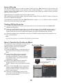
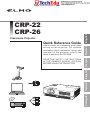
Use this book as a reference guide when
setting up the projector. For detailed
information about installation, setup, and
operation of the projector, refer to the
owner’s manual on the CD-ROM.
Español
Quick Reference Guide
Italiano
Classroom Projector
Português
CRP-22
CRP-26
Installing the Projector in Proper Position
Install the projector properly. Improper Installation may
reduce the lamp life and cause a fire hazard.
Do not point the projector up to project an
image.
Do not tilt the projector more than 20
degrees from side to side.
Do not point the projector down to project an
image.
Do not pitch the projector more than
30 degrees above and below.
30°
30°
Do not put the projector on either side to
project an image.
Moving the Projector
When moving the projector, replace the lens cap and retract adjustable feet to prevent damage to the lens and
cabinet.
When the projector is not in use for an extended period, put it into a suitable case with the lens side up.
Safety Precaution
SIDE and TOP
Allowing the proper amount of space on the top, sides,
and rear of the projector cabinet is critical for proper
air circulation and cooling of the unit. The dimension
shown here indicate the minimum space required.
If the projector is to be built into a compartment or
similarly enclosed, these minimum distances must be
maintained.
REAR
0.7’(20cm)
1.5’(50cm)
Connecting the AC Power Cord
3’(1m)
3’(1m)
20cm
This projector uses nominal input voltages of 100–120 V or 200–240 V AC and it automatically selects the correct
input voltage.
CAUTION
50cm
1m
1m
The AC outlet must be near this equipment and must
be easily accessible.
Note:
Unplug the AC power cord when the projector is
not in use. When this projector is connected to an
outlet with the AC power cord, it is in Stand-by
mode and consumes a little electric power.
Connect the AC power cord
(supplied) to the projector.
NOTE ON THE POWER CORD
AC power cord must meet requirement of the country where you use the projector.
Confirm the AC plug type with the chart below and proper AC power cord must be used.
If supplied AC power cord does not match your AC outlet, contact your sales dealer.
Projector side
AC outlet side
For the U.S.A. and Canada
For Continental Europe
For the U.K.
Ground
To power cord
connector on your
projector.
To the AC outlet.
(120 V AC)
To the AC outlet.
(200 - 240 V AC)
2
To the AC outlet.
(200 - 240 V AC)
① Top controls and Indicators
② Zoom Ring
③ Focus Ring
④ Speaker
⑤ Infrared Remote Receiver
⑥ Projection Lens
⑦ Lens Cap
Front
② ③
①
④
⑤
⑦
⑥
Do not turn on a projector with lens cap
attached. High temperature from light beam
may damage lens cap and result in fire
hazard.
⑧
⑧ Air Intake Vent
Back
⑨
⑩
⑨ Lamp Cover
⑩ Terminals and Connectors
⑪ LAN Connection Terminal
⑫ Power Cord Connector
⑬ Exhaust Vents
⑪
CAUTION
Hot air is exhausted from the exhaust
vent. Do not put heat-sensitive objects
near this side.
⑫⑬
Bottom
*
⑬
⑭
⑭ Filters
⑮ Adjustable Foot
⑧
Note:
⑭
⑪ LAN Connection Terminal is for the
Network function. Refer to the owner’s
manual of “Network Set-up and Operation”.
⑮
Kensington Security Slot
This slot is for a Kensington lock used to
deter theft of the projector.
Kensington is a registered trademark of ACCO Brands Corporation.
3
English
CAUTION
Rear Terminal
①
③
②
④
⑤
⑦
⑧
⑥
⑤ VIDEO IN
Connect the composite video output signal
to this jack.
① CONTROL PORT
When the projector is controlled by a
computer, connect to this jack with serial
control cable.
⑥ LAN Connection Terminal
Connect the LAN cable (refer to the owner’s
manual of “Network Set-up and Operation”).
② COMPUTER IN 1 /S-VIDEO IN /
COMPONENT IN
Connect analog RGB output signal from
a computer, S-VIDEO output signal from
video equipment, or RGB scart 21-pin video
output or component video output to this
terminal.
⑦ AUDIO IN
Connect the audio output signal from
computer or video equipment to this jack.
⑧ DC OUT 12V 1.1A
Connect the DC power cord (supplied) to
this jack to supply DC 12V to a document
camera.
③ COMPUTER IN 2 / MONITOR OUT
– Connect analog RGB output signal from a
computer to this terminal.
– This terminal can be used to output the incoming analog RGB and Component signal from COMPUTER IN 1 /S-VIDEO IN /COMPONENT IN terminal to the other monitor.
Notes on using ELMO document cameras;
- The projector can supply 12V DC power to the
document camera "L-1ex/TT-02RX" or "L-1n/
TT-02s" with setting to Network mode of
Standby mode menu.
- Do not connect any other document cameras
other than ELMO "L-1ex/TT-02RX" and "L-1n/
TT-02s" with the supplied VGA/DC power
combined cord. Otherwise damages may
result.
- Use only the supplied VGA/DC power
combined cord.
- When DC OUT 12V jack is plugged in, the
cooling fans are running even if the projector is
in standby mode.
④ AUDIO OUT (VARIABLE)
Connect an external audio amplifier to this
jack.
This terminal outputs sound from AUDIO IN
terminal.
4
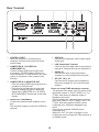
Top Panel
③ AUTO SETUP button
Execute the setting of Auto setup (includes
Input search, Auto PC adj. and Auto
Keystone functions) in the setting menu.
⑤
④
⑦
③
④ ON/STAND–BY button
Turn the projector on or off.
⑤ POWER indicator
–Lights red when the projector is in standby mode.
–Lights green during operations.
–Blinks green in the Power management
mode.
②
⑥
⑥ MENU button
Open or close the On-Screen Menu.
①
⑦ LAMP REPLACE indicator
Lights yellow when the projection lamp
reaches its end of life.
① SELECT button
–Execute the selected item.
–Expand or compress the image in the
Digital zoom mode.
⑧ WARNING indicator
–Lights red when the projector detects an
abnormal condition.
–Blinks red when the internal temperature of
the projector exceeds the operating range.
② POINT ▲▼◄► (VOLUME +/–) buttons
–Select an item or adjust the value in the
On-Screen Menu.
–Pan the image in the Digital zoom +/mode.
–Adjust the volume level (Point
◄►buttons).
Remote Control Battery Installation
1
Open the battery
compartment lid.
2
Install new batteries into
the compartment.
Two AAA size batteries
For correct polarity (+
and –), be sure battery
terminals are in contact
with pins in compartment.
3
Replace the
compartment lid.
To ensure safe operation, please observe the following precautions :
● Use two (2) AAA or LR03 type alkaline batteries.
● Always replace batteries in sets.
● Do not use a new battery with a used battery.
● Avoid contact with water or liquid.
● Do not expose the remote control to moisture or heat.
● Do not drop the remote control.
● If the battery has leaked on the remote control, carefully wipe the case clean and install
new batteries.
● Risk of an explosion if battery is replaced by an incorrect type.
● Dispose of used batteries according to the instructions or your local disposal rule or guidelines.
5
English
⑧
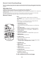
Remote Control Operating Range
Point the remote control toward the projector (Infrared Remote Receiver) when pressing the buttons.
Maximum operating range for the remote control is about 16.4'(5 m) and 60 degrees in front of the
projector.
Adjustable Foot
Projection angle can be adjusted up to 10.0 degrees with the adjustable foot.
Lift the front of the projector and push the foot lock latch on the projector.
Release the foot lock latch to lock the adjustable foot and rotate the adjustable foot to adjust the
position and tilt.
To retract the adjustable foot, lift the front of the projector and push and undo the foot lock latch.
Keystone distortion of the projected image can be corrected by menu operation.
Remote Control
Note:
To ensure safe operation, please observe the following
precautions:
– Do not bend, drop, or expose the remote control to moisture or
heat.
– For cleaning, use a soft dry cloth. Do not apply benzene,
thinner, spray, or any chemical material.
②
①
③
④
⑤
⑳
⑲
⑥
⑦
⑧
⑨
⑩
⑪
⑫
⑱
⑰
⑯
⑮
⑭
⑬
① ON/STAND-BY button
Turn the projector on or off.
You can also turn the document camera on or off with this button.
② AUTO SET button
Correct vertical keystone distortion and adjust computer
display parameters such as Fine sync., Total dots, and
Picture position.
③ COMPUTER 1/2 buttons
Select the COMPUTER 1 or COMPUTER 2 input source.
④ VIDEO button
Select the VIDEO input source.
⑤ S-VIDEO button
Select the S-VIDEO input source.
⑥ Point ▲▼◄► buttons
– Select an item or adjust the value in the On-Screen Menu.
– Pan the image in the Digital zoom +/- mode.
⑦ SCREEN button
Select a screen mode.
⑧MENU button
Open or close the On-Screen Menu.
⑨ FREEZE button
Freeze the picture on the screen.
⑩ NO SHOW button
Temporarily turn off the image on the screen.
⑪ D.ZOOM ▲▼ buttons
Zoom in and out the images.
To be continued on the next page.
6
⑫ VOLUME +/- buttons
Adjust the volume level.
⑱ KEYSTONE button
Correct keystone distortion.
⑬ MUTE button
Mute the sound.
⑲ SELECT button
– Execute the selected item.
– Expand or compress the image in Digital
zoom mode.
⑭ IMAGE button
Select the image mode.
⑳ COMPONENT button
Select the COMPONENT input source.
⑮ P-TIMER button
Operate the P-timer function.
English
⑯ LAMP button
Select a lamp mode.
⑰ INFO. button
Operate the information function.
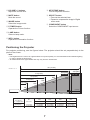
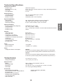
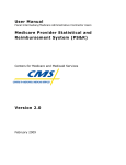
Positioning the Projector
For projector positioning, see the figures below. The projector should be set perpendicularly to the
plane of the screen.
Note:
• The brightness in the room has a great influence on picture quality. It is recommended to limit ambient lighting
in order to obtain the best image.
• All measurements are approximate and may vary from the actual sizes.
38.7'(11.80m)
A:B = 6:1
(Inch Diagonal)
32.3'(9.84m)
21.5'(6.55m)
Max. Zoom
16.1'(4.90m)
200"
10.7'(3.26m)
4.3'(1.30m)
150"
100"
40"
300"(tele )
300"(wide)
Min. Zoom
250
167
A
125
83
(Center)
B
Screen Size
(W x H) mm
4 : 3 aspect ratio
40”
100”
150”
200”
300”
813 x 610
2032 x 1524
3048 x 2286
4064 x 3048
6096 x 4572
Zoom (max)
4.3'(1.30m)
10.7'(3.26m)
16.1'(4.90m)
21.5'(6.55m)
32.3'(9.84m)
Zoom (min)
5.1'(1.55m)
12.9'(3.92m)
19.4'(5.90m)
25.8(7.87m)
38.7'(11.80m)
7
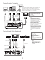
Connecting to a Computer
Monitor
Output
Monitor Input
or
Monitor Output
VGA cable
COMPUTER IN 1
/S-VIDEO
/COMPONENT IN
Note:
Use only the supplied VGA/DC power combined cord.
(Document camera can be powered separately by
AC/DC power supply came with the ELMO document
camera "L-1ex/TT-02RX" or "L-1n/TT-02s".)
RGB
Output
DC IN
12V
External Audio Equipment
VGA/DC power
combined cord
COMPUTER IN 2 /
MONITOR OUT
Audio Input
Cables used for connection
• VGA Cables (Mini D-sub 15 pin)
• VGA/DC power combined cord (supplied)
• Audio Cables
Audio cable
(stereo)
Audio cable (stereo)
Audio
Output
VGA cable
Document Camera
DC OUT 12V
AUDIO OUT
(stereo)
This terminal is switchable. Set up the terminal
as either Computer input or Monitor output.
AUDIO IN
Note:
• Input sound to the AUDIO IN
terminal when using the
COMPUTER IN 1/ S-VIDEO IN /
COMPONENT IN and the
COMPUTER IN 2/MONITOR
OUT terminals as input.
• When the AUDIO OUT is
plugged-in, the projector's built-in
speaker is not available.
• When the cable is of the longer
variety, it is advisable to use the
COMPUTER IN 1 /S-VIDEO IN /
COMPONENT IN and not the
COMPUTER IN 2/MONITOR
OUT.
Connecting to Video Equipment
External Audio Equipment
S-Video
Output
Audio
Output
Audio
Input
Composite Video and Audio Output
Note:
COMPUTER IN 1
/S-VIDEO
/COMPONENT IN
AUDIO IN
Audio cable
(stereo)
Audio cable
(stereo)
S-Video cable
S-Video-VGA cable
Cables used for connection
• Video Cable
• S-Video Cable
• S-Video-VGA Cable
• Audio Cables (Mini Plug: stereo)
(Cables are not supplied with the projector. )
AUDIO OUT
(stereo)
Video cable
VIDEO IN
8
When the AUDIO OUT is
plugged-in, the projector's
built-in speaker is not
available.
Connecting to Component Video Equipment
External Audio Equipment
Audio Output
Component Video Output
(Y, Pb/Cb, Pr/Cr)
RGB Scart
21-pin Output
Audio Input
Audio cable (stereo)
Scart-VGA
cable
Audio cable
(stereo)
ComponentVGA cable
COMPUTER IN 1/ S-VIDEO IN / COMPONENT IN
AUDIO OUT
(stereo)
Cables used for connection
• Audio Cables (Mini Plug: stereo)
• Scart-VGA Cable
• Component Cable
• Component-VGA Cable
(Cables are not supplied with this projector.)
Note:
When the AUDIO OUT is plugged in, the projector's built-in speaker is
not available.
AUDIO IN
Turning On the Projector
1
Complete peripheral connections (with a
computer, VCR, etc.) before turning on the
projector.
2
Connect the projector’s AC power cord into
an AC outlet. The POWER indicator lights
red. Open the lens cap.
3
Press the ON/STAND-BY button on the
top control or on the remote control.
The POWER indicator lights green and
the cooling fans start to operate. The
preparation display appears on the screen
and the count down starts.
4
After the countdown, the input source that
was selected the last time and the lamp
control status icon appear on the screen.
5
If there is no signal input when start on the
projector, or the current signal is missed
while operating the projector, the Video/PC
selection window will be displayed on the
screen, please move the pointer to input
source desired by pressing the Point ▲▼
buttons and press the SELECT button. And
then follow the input signal guidance window
to correct the signal and connection.
If the projector is locked with a PIN code,
PIN code input dialog box will appear. Enter
the PIN code as instructed on the next page.
Note:
- The projector can be turned ON or OFF by pressing the POWER button on the remote control of the specified document camera ("L-1ex/TT-02RX" or "L-1n/TT-02s").
- The projector can be turned off with this remote
by pressing once; however, the "Power Off?" indicator on the screen will not be displayed.
- While the POWER indicator is blinking, the lamp is being cooled down and the projector cannot be turned back on.
Note:
•When the Logo select function is set to Off,
the logo will not be shown on the screen.
•If the PIN code number is not entered within
three minutes after the PIN code dialog box
appeared, the projector will be turned off
automatically.
•The "1234" is set as the initial PIN code at
the factory.
What is PIN code?
PIN (Personal Identification Number) code is a
security code that allows the person who knows
it to operate the projector. Setting a PIN code
prevents unauthorized use of the projector.
9
English
Component
cable
Enter a PIN code
Use the Point ▲▼ buttons to enter a number. Press the Point ◄► buttons to fix the number and
move the red frame pointer to the next box. The number changes to . If you fixed an incorrect
number, use the Point ◄► buttons to move the pointer to the number you want to correct, and then
enter the correct number.
Repeat this step to complete entering a four-digit number.
After entering the four-digit number, move the pointer to Set. Press the SELECT button so that you
can start to operate the projector.
If you entered an incorrect PIN code, PIN code and the number () will turn red for a moment.
Enter the correct PIN code all over again.
Turning Off the Projector
1
Press the ON/STAND-BY button on the top control or on the remote control, and Power off?
appears on the screen.
2
Press the ON/STAND-BY button again to turn off the projector. The POWER indicator starts to
blink red, and the cooling fans keep running. (You can select the level of fans’ quietness and
speed. At this time, you can unplug the AC power cord even if the fans are still running.)
3
When the projector has cooled down enough, the POWER indicator stops blinking and you can
turn on the projector.
Note:
Do not put the projector in a case before the projector is cooled enough.
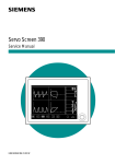
How to Operate the On-Screen Menu
The projector can be adjusted or set via the
On-Screen Menu. For each adjustment and
setting procedure, refer to the respective
sections in this manual.
1
2
3
4
5
On-Screen Menu
Press the MENU button on the top control or
the remote control to display the On-Screen
Menu.
Use the Point ▲▼ buttons to highlight
or select a main menu item. Press the
Point ► or the SELECT button to access
the submenu items. (The selected item is
highlighted in orange.)
Point ► or
SELECT
button
Use the Point ▲▼ buttons to select the
desired submenu item and press the
SELECT button to set or access the selected
item.
Use the Point ▲▼◄► buttons to adjust the
setting or switch between each option and
press the SELECT button to activate it and
return to the submenu.
Press the Point ◄ button to return to the
main menu; press the MENU button again to
exit the On-Screen Menu.
10
The selected item is
highlighted in orange.
The currently set item
is check marked.
Audio
Internal Audio Amp
Built-in Speaker
1.0 W RMS
1 speaker, ø1.1” (28mm)
Power
Voltage and Power Consumption
CRP-22:
AC 100–120 V (3.3A Max. Ampere), 50/60 Hz (The U.S.A and Canada)
AC 200–240 V (1.8A Max. Ampere), 50/60 Hz (Continental Europe and The U.K.)
CRP-26:
AC 100–120 V (3.5A Max. Ampere), 50/60 Hz (The U.S.A and Canada)
AC 200–240 V (1.9A Max. Ampere), 50/60 Hz (Continental Europe and The U.K.)
Operating Environment
Operating Temperature
41˚F–95˚F (5 ˚C–35 ˚C)
Storage Temperature
14˚F–140˚F (-10˚C–60 ˚C)
Remote Control
Battery
Operating Range
Dimensions
Net Weight
Accessories
Owner’s Manual (CD-ROM)
Quick Reference Guide & Safety Manual
AC Power Cord
Remote Control and Batteries
VGA/DC power combined cord
Lens Cap with String
PIN Code Label
AAA or LR03 1.5V ALKALINE TYPE x 2
16.4’ (5 m)/±30˚
2.0” (W) x 0.7” (H) x 4.3” (D) (52 mm x 18 mm x 110 mm)
2.37 oz (67 g) (including batteries)
Network Application (CD-ROM)
Ferrite core
11
English
Technical Specifications
Mechanical Information
Projector Type
Classroom Projector
Dimensions (W x H x D)
13.13” x 3.35” x 9.72” (333.5mm x 85.2mm x 247.0mm) (Not including protrusions)
Net Weight
5.5 lbs (2.5 kg)
Foot Adjustment
0˚ to 10˚
Panel Resolution
LCD Panel System
0.55” TFT Active Matrix type, 3 panels
Panel Resolution
1,024 x 768 dots
Number of Pixels
2,359,296 (1,024 x 768 x 3 panels) Signal Compatibility
Color System
PAL, SECAM, NTSC, NTSC4.43, PAL-M, and PAL-N
SD/HDTV Signal
480i, 480p, 575i, 575p, 720p, 1035i, and 1080i
Scanning Frequency
H-sync. 15 kHz–100 kHz, V-sync. 50–100 Hz
Optical Information
Projection Image Size (Diagonal)
Adjustable from 40” to 300”
Throw Distance
4.3’ - 38.7’ (1.30m - 11.80m)
Projection Lens
F 2.0 ~ 2.15 lens with f 18.38 mm ~ 22.06 mm with manual zoom and focus
Projection Lamp
220 W Interface
Video Input Jack
RCA Type x 1
Audio Input Jack
Mini Jack (stereo) x 1
Computer In 1/ S-video In Mini D-sub 15 pin x 1
/ Component Input Terminal
Computer In 2 / Monitor Out Terminal
Mini D-sub 15 pin x 1
Control port D-sub 9 pin x 1
Audio Output Jack
Mini Jack (stereo) x 1 (variable)
LAN Connection Terminal
RJ45
DC Output Jack
DC 12V, 1.1A