1
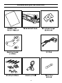
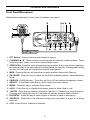
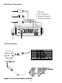
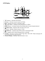
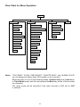
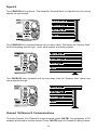
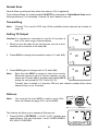
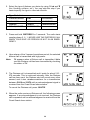
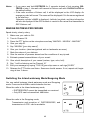
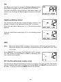
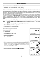
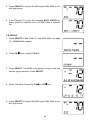
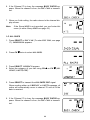
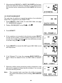
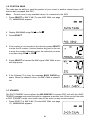
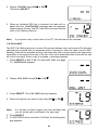
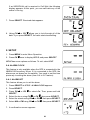
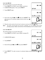
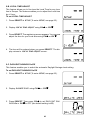
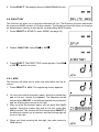
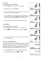
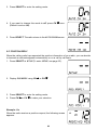
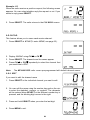
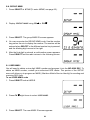
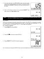
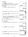
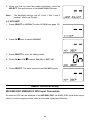
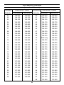
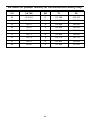
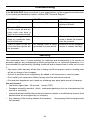
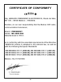
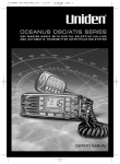
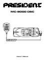
MC-8000 DSC
Owner’s Manual
Contents
Included with your MC-8000 DSC ......................................................................................... 4
Controls and Indicators ......................................................................................................... 5
Fornt Panel/Microphone ............................................................................................ 5
Rear Panel Connectors ............................................................................................. 6
ACC Connectors ........................................................................................................ 6
LCD Display ............................................................................................................... 7
Flow Chart for Menu Operation ................................................................................. 8
Installation ............................................................................................................................. 9
Choosing a Location .................................................................................................. 9
Engine Noise Suppression ........................................................................................ 9
Installing the MC-8000 DSC ...................................................................................... 9
Operation ............................................................................................................................ 10
Power On/Off ........................................................................................................... 10
Last Channel Memory ............................................................................................. 10
Squelch .................................................................................................................... 11
Channel 16/Channel 9 Communications ................................................................. 11
Triple Watch ............................................................................................................. 12
Manual Tuning ......................................................................................................... 12
Mem (Entering channel numbers into Memory Scan) ............................................. 12
Triple Watch Scan ................................................................................................... 12
Normal Scan ............................................................................................................ 13
Transmitting ............................................................................................................. 13
Setting TX Output .................................................................................................... 13
Distress .................................................................................................................... 13
Switching the Inland waterway Mode / Seagoing Mode .......................................... 15
P.A. .......................................................................................................................... 15
High/Low Battery betect .......................................................................................... 15
GPS ......................................................................................................................... 16
UIC ........................................................................................................................... 16
Menu Operation .................................................................................................................. 17
Digital Selective Calling (DSC) ................................................................................ 17
Individual ...................................................................................................... 17
Group ........................................................................................................... 18
All Ships ....................................................................................................... 19
Position Request .......................................................................................... 20
Position Send ............................................................................................... 21
Standby ........................................................................................................ 21
Call Wait ....................................................................................................... 22
Setup ....................................................................................................................... 23
Alarm Clock .................................................................................................. 23
Local Time Adjust ......................................................................................... 25
Daylight Savings On/Off ............................................................................... 25
Directory ....................................................................................................... 26
Auto Channel Switch .................................................................................... 27
Position Reply .............................................................................................. 28
CH Tag ......................................................................................................... 29
Group MMSI ................................................................................................. 30
User MMSI .................................................................................................... 30
Atis ID ........................................................................................................... 31
System ..................................................................................................................... 32
Contrast ........................................................................................................ 32
Lamp Adjust ................................................................................................. 32
Key Beep ...................................................................................................... 33
NMEA Technical Setup ....................................................................................................... 33
VHF FM Marine Radio Telephone Channel and Functions (International Channels) ......... 34
EXTENDED CH .................................................................................................................. 35
Specification ........................................................................................................................ 36
Troubleshooting .................................................................................................................. 37
Warranty ............................................................................................................................ 37
Certificate of Conformity ..................................................................................................... 38
Included with your MC-8000 DSC
4
Controls and Indicators
Front Panel/Microphone
Alphanuméric keyboard for direct input of channels ans names
1. PTT Switch - Press to transmit and release to receive.
2. CHANNEL ▲ / ▼ - These keys are used to change the channel number up/down. These
buttons are also used to move the cursor in Menu mode.
3. STEP/SCAN - Press this key to activate the step operation. Every time this key is pushed,
the radio will step to the next channel that has placed into Memory. Pressing and holding
this key for 2 seconds will activate the channel scan feature.
4. MEM - Pressing this key will place the currently selected channel into Memory.
5. PA / MODE - Press this key to enable the PA (Public Address) feature / Inland Waterway
Mode
6. PWR/VOL (On/Off/Volume) - Turns the unit On or Off and adjusts the speaker volume.
7. SELECT - In the Menu mode this is used to select the menu options.
8. MENU - Press this key to enter the Menu mode.
9. HI/LO - Press this key to change the transmit power to either High or Low.
10. 16/9/TRI - Press this key instantly change to Channel 16, Channel 9 or current channel.
Pressing and holding this key for 2 seconds will activate the triple Watch Feature.
11. DISTRESS - Press this key to send a signal of distress in case of emergency.
12. SQUELCH - Rotate this knob eliminate background noise when a signal is not being
received.
13. CLR - Press this key to delete a character.
5
Rear Panel Connectors
1
1. DC Jack
2. ACC Connector
3. Remote Connector
4. Antenna Connector
2
3
4
ACC Connectors
6
LCD Display
2
1
4 6
3 5
7
8
9
11
WX
10
1. TX (Transmit) - Indicates transmitting.
2. HI (High) - Indicates transmit output is 25 Watts.
3. DSC - Indicators the radio is in the DSC mode.
4. TRI (Triple Watch) - Indicates Triple Watch Mode is in effect.
5. MEM (Memory) - Indicates Memory Scan Mode status for each channel selected.
6.
(Alarm Icon) - It appears when the alarm clock is set.
7. LO (Low) - Indicates transmit output is 1 Watt.
8.
(GPS Icon) - It appears while GPS module is receiving the data.
9. WX - It appears when Inland Waterway Mode is selected.
10. CH TAG - This area is used for Channel Tag, Menu, DSC, GPS. These messages will
continually scroll from right to the left.
11. Channel Display - Indicates Channel Number in use.
7
Flow Chart for Menu Operation
MENU
DSC CALL
SYSTEM
SETUP
INDIVIDUAL
ALARM CLOCK
CONTRAST
GROUP
LOCAL TIME ADJUST
LAMP ADJUST
ALL SHIPS
DAYLITYE SAVE
KEY BEEP
POS REQUEST
DIRECTORY
EXIT
POS SEND
AUTO CH SW
STANDBY
POS REPLY
CALL WAIT
CH TAG
EXIT
GROUP MMSI
EXIT
USER MMSI
ATIS ID
EXIT
Notes: “POS SEND”, “LOCAL TIME ADJUST”, “DAYLITE SAVE”, and “ALARM CLOCK”
are not displayed in Menu when GPS module is not connected.
When the radio is in one of the following modes: Channel 16/9 mode, Scan Mode,
or Triple Watch mode, and the user presses the Menu key, all the of these modes
are cancelled.
The menu mode will be cancelled if the radio receives a DSC call or EXIT
is selected.
8
Installation
Caution:The MC-8000 DSC will only operate with a nominal 12 volt negative ground battery
system.
It is important to carefully determine the most suitable location for your radio on your vessel.
Electrical, mechanical, and environmental considerations must all be taken into account. You
should select the optimum relationship among these considerations.
Keep in mind the flexibility designed into the MC-8000 DSC so that you can most conveniently use it. Features which should be considered are:
1. The universal mounting bracket may be installed on either the top or bottom of a shelf, on
a bulkhead, or for overhead mounting.
2. The REMOTE speaker wires can be used with an auxiliary speaker.
3. All connections are “plug-in” type for easy removal of the radio.
Choosing a Location
Some important factors to consider in selecting the location for your MC-8000 DSC.
1. Select a location that is free from spray and splash.
2. Keep the battery leads as short as possible. Direct connection to the battery is most
desirable.
3. Keep the antenna lead as short as possible. Long antenna leads can cause substantial
loss of performance for both receiving and transmitting.
4. Locate your antenna as high as possible and clear from metal objects. The reliable range
of coverage is a direct function of the antenna height.
5. Select a location that allows free air flow around the heat sink on the rear of the radio.
6. Select a location well away from the ship’s compass. Auxiliary speakers also should be
located away from the compass.
Engine Noise Suppression
Interference from the noise generated by the electrical systems of engines is sometimes a
problem with radios. The MC-8000 DSC has been designed to be essentially impervious to
ignition noise and alternator noise. However, in some installations it may be necessary to
take measures to further reduce the effect of noise interference. All DC battery wires, antenna lead, and accessory cables should be routed away from the engine and engine compartment, and from power cabling carrying high currents.
Installing the MC-8000 DSC
After you have carefully considered the various factors affecting your choice of location,
position the radio (with the bracket, microphone, power cord, antenna and any auxiliary cables installed) into the selected location to assure there is no interference with the surrounding items. Mark the location of the mounting bracket. Remove the bracket from the radio and
use it as a template to mark the holes to be drilled for the mounting hardware. Drill the holes
and mount the bracket with hardware compatible with the material of the mounting surface.
9
Note:
This HEXAGON HEAD BOLT is only for mounting the bracket
with hardware. Do not use it for installing the radio in the
mounting bracket.
Connect the red wire of the supplied power cord to the positive (+)
battery supply. Connect the black wire of the power cord to the negative (-) battery supply. The power cord is equipped with a fuse to protect the radio. Use only a six (6) ampere fast blow fuse for replacement. Connect the power cord to the keyed connector on the power
“pigtail”.
Connect the antenna and all other auxiliary cables and accessories.
Install the radio in the mounting bracket and connect all cables
and accessories to the appropriate jacks and connectors.
Note:
Do not use any other mounting knobs than the ones enclosed. Do not insert the knobs without attaching the
bracket.
Operation
Power On/Off
Turn the unit On by rotating the PWR/VOL control clockwise.
Adjust the volume to a comfortable level.
When you turn the unit On, you will hear a beep, and the greeting message below appears on the LCD for 3 seconds.
Note:
When you turn On the radio for the first time after purchase, the channel 16 will
appear on the LCD.
Last Channel Memory
The MC-8000 DSC memorizes the last channel selected before you turn Off the radio. For
example, if you turn Off the radio on CH 12, it will be on that channel when turned back On.
Note:
In order for the last channel to be memorized, you must have the radio on that
channel for 3 seconds.
10
Squelch
Turn SQUELCH fully clockwise. This raises the “Squelch Gate” so high that only very strong
signals can get through.
Turn SQUELCH fully counterclockwise until you hear a hiss. This lowers the “Squelch Gate”
so that everything gets through - noise, weak signals, and strong signals.
Turn SQUELCH back clockwise until the hiss stops. Now the “Squelch Gate” allows only
strong signals through.
Channel 16/Channel 9 Communications
To access Channel 16 or Channel 9 communications, press 16/9/TRI. You can access 16 CH
instantly while tuned to another channel. Press 16/9/TRI again for Channel 9 Calling commu11
nications. Press 16/9/TRI a third time to return to the channel selected prior to accessing
Channel 16/Channel 9 communications.
The display will indicate the selected channel.
To cancel Channel 16/Channel 9 communications:
• Press 16/9/TRI until the previous channel setting appears.
- - or - • Press CH ▲ , CH ▼ or STEP/SCAN.
Triple Watch
Triple Watch monitors Channel 16, Channel 9, and the current Marine Channel.
To activate Triple Watch, press and hold 16/9/TRI for 2 seconds.
TR I appears on the LCD, indicating Triple Watch mode is in effect. If a signal is received on either Channel 16 or Channel 9,
the radio remains on that channel until the signal ends.
Press and hold 16/9/TRI for 2 seconds to cancel the Triple Watch
mode.
Note:
While in Triple Watch mode, you can change the currently selected channel using CH ▲ or CH ▼ .
A momentary press of the 16/9/TRI button interrupts Triple Watch mode and remains on channel 16, or on channel 9 if you press 16/9/TRI once more. To return to
the Triple Watch mode, simply press the button again.
Manual Tuning
To manually select a channel, press CH ▲ or CH ▼ or use the number key pad on the mic
and press SELECT. Communication channels are located on channel 01-28 and 60-88. Channel 70 is used for DSC only, user cannot select this channel.
Mem (Entering channel numbers into Memory Scan)
You can enter channels into Memory Scan for instant scanning at any time. When a channel
is selected for Memory Scan, MEM appears on the LCD display.
To enter a channel into Memory Scan, select the channel you
want to store by using CH ▲ or CH ▼ or use the number key pad
on the mic and press SELECT, and then press MEM. The channel is stored in Memory Scan and MEM appears on the LCD
display.
To cancel the channel in Memory, press MEM. The MEM icon
disappears.
Triple Watch Scan
To turn Triple Watch Scan On, press and hold STEP/SCAN for 2 seconds. While the current
channel is scanned, Channel 16 and Channel 9 are also scanned every 2 seconds. Then TRI
appears.
12
Normal Scan
Normal Scan is performed only when the memory CH is registered.
To turn Normal Scan On, press and hold 16/9/TRI for 2 seconds in Triple Watch Scan mode.
Although Memory CH is scanned, Channel 16 and Channel 9 are not.
Transmitting
Note:
Channel 70 is used for DSC only. All the available marine channel are located on
page 34.
Setting TX Output
Caution:It is important to remember to use the LO position in
port or for short range communications.
1. When you turn the radio On for the first time, the unit is automatically set to transmit at 25 watts (HI).
2. Press HI/LO to change the transmitter output to 1 watt (LO).
3. Press HI/LO again to change back to 25 watts (HI).
Note:
Each time the HI/LO is pressed a short tone sounds.
When the channel is set as LO power channel, you can
transmit at 25 watts (HI) by pressing and holding HI/LO
during the call (except for CH 75 and CH 76).
Transmit time is limited to 5 minutes. TX icon and channel number blinks when
transmit time is over 5 minutes.
Distress
Note:
You must set the user MMSI in order to send a Distress call.Please see page 30 to set the MMSI.
This feature will allow you to transmit a Distress call.
1
Press QUICKLY DISTRESS, UNDESIGNATED appears ans
starts blinking. You can skip steps 1 and 2 WHEN IMMEDIATE HELP IS NEEDED.
13
2. Select the type of distress you desire by using CH ▲ and ▼
(fire, flooding, collision, etc.). You may skip this step if you
cannot specify the type in a hurried situation.
Type Code List
UNDESIGNATED
FIRE
FLOODING
COLLISION
GROUNDING
CAPSIZING
SINKING
ADRIFT
ABANDONING
PIRACY/ARMED
OVERBOARD
3. Press and hold DISTRESS for 3 seconds. The radio starts
counting down 3, 2, 1. NEVER USE THE DISTRESS CALL
WHEN YOUR SHIP OR PERSON IS NOT IN AN EMERGENCY.
4. Upon elapse of the 3 second countdown period, the selected
distress call is transmitted with high power.
Note:
TX appears when a Distress call is transmitted. Make
sure the Distress call has been transmitted by checking
the status of TX.
5. The Distress call is transmitted and it waits for about 210 270 seconds. This is continued internally. After the Distress
call has been sent, the Distress alert will sound every other
second, and it also «shadow-watches» for a transmission
between CH16 and CH70 until an acknowledgment signal is
received from the Coast Guard shore station.
To cancel the Distress call, press 16/9/TRI.
6. When the radio receives a Distress call, the following screen
appears. If an acknowledgment is not received, the Distress
call is repeated until an acknowledgment is received from the
Coast Guard shore station.
14
Notes: • If you press and hold DISTRESS for 3 seconds instead of just pressing DISTRESS at step 1, the radio will transmit a Distress call with UNDESIGNATED as
the default setting.
• If the radio receives a Distress call, it will be displayed on the LCD display. An
emergency alert will sound. The name will be displayed if it is the name registered
in the directory.
Otherwise, sender’s MMSI is displayed. Latitude, longitude, and time information
will also be displayed if the GPS module is carried in the vessel that transmitted a
DSC Distress call.
MARINE DISTRESS PROCEDURE
Speak slowly, clearly, calmy.
1. Make sure your radio is ON.
2. Tune to Channel 16.
3. Press the PTT button on the microphone and say “MAYDAY - MAYDAY - MAYDAY”
4. Give your ship ID.
5. Say “MAYDAY [your ship name]”
6. Give your location: (what navigational aids or landmarks are near).
7. State the nature of your distress.
8. Give the number of persons aboard and the conditions of any injured.
9. Estimate present seaworthiness of your vessel.
10. Give a brief description of your vessel (meters, type, color, hull).
11. Say: “I will be listening on the Channel 16”
12. End your message by saying “THIS IS [your ship name or call sign] OVER.”
13. Release the PTT button and listen. Someone should asnwer. If not, repeat call, beginning at item 3 above.
Switching the Inland waterway Mode/Seagoing Mode
You can switch between Inland waterway mode and Seagoing
mode. Press and hold PA to switch between the two.
When the radio in the Inland waterway mode;
• DISTRESS/DSC cannot be transmitted nor received.
• Only ATIS can be transmitted. WX blinks.
When the radio in the Seagoing mode;
Transmission and reception of DISTRESS/DSC, and
transmission of ATIS can be available.
15
WX
P.A.
The PA key will be used to activate the Public Address feature.
When PA key is pushed, the LCD screen will be as follows.
Push and hold PTT on the microphone, and speak clearly in a
normal voice. Pushing the PA key again will return to the radio
mode.
High/Low Battery detect
This feature will allow the user to detect a battery condition. The
display of a battery is not performed when DSC is received.
When the radio detect battery low (11 V), the following screen
appears.
When the radio detect battery high (16 V), the following screen
appears.
GPS
Note:
When the external GPS modulate is not connected, GPS Icon will start blinking.
When the external GPS modulate is connected trough the NMEA0183 jack, GPS
Icon is fixe.
Press SELECT. The message “WAITING GPS DATA” appears.
The radio meets the requirements of GPS by displaying date,
time, latitude and longitude.
UIC (for the authorized country only)
This feature can change the following 3 modes of operation; USA, INT ans CAN. This hidden
feature is enabled when user is pushing and holding HI/LO and SELECT keys and turns on
the radio. To change mode press MEM more than 2 seconds.
16
Menu Operation
You can enter in the menu all its functions from the mic.
1. DIGITAL SELECTIVE CALLING (DSC)
Digital Selective Calling is a process of establishing a radio call, it has been chosen by the
International Maritime Organization (IMO) as an international standard for establishing VHF,
MF and HF radio calls. Digital Selective Calling has also been selected as part of the Global
Maritime Distress and Safety System (GMDSS).
This service will let you instantly send a Distress call with GPS position (when optional GPS
receiver is connected to the MC-8000 DSC) to the US Coast Guard and other vessels within
range of the transmission. DSC will also let you initiate or receive distress, urgency, safety,
position information and routine calls to or from another vessel outfitted with a DSC transceiver.
See the directory section 2-D (p. 26) for instructions on how to setup the directory of names.
Note:
• Position SEND and ALARM CLOCK will not be displayed if GPS is not connected.
• Refer to page 8 for the flow chart of Menu Operation.
1. Press MENU to enter Menu Operation.
2. Press SELECT to enter DSC CALL.
DSC CALL has 7 options as follows.
To exit, select EXIT.
1-A. INDIVIDUAL
1. Press SELECT at DSC CALL.
2. INDIVIDUAL appears.
Press SELECT.
3. If the contact is not recorded in the directory press SELECT
to enter the ID number. Use the Number key pad on the mic
to enter the number otherwise select the individual you want
to contact using CH ▲ or CH ▼ .
4. Select Inter-Ship Channel by CH ▲ or CH ▼ key.
17
5. Press SELECT to transmit the DSC signal. DSC CALL is sent
with high power.
6. If the CHannel 70 is busy the message BUSY CHECK appears. When the channel is free, the DSC CALL is transmitted.
1-B. GROUP
1. Press SELECT at DSC CALL (To enter DSC CALL, see page
17). INDIVIDUAL appears.
2. Press CH ▼ once to select GROUP.
3. Press SELECT. The MMSI code appears, and you can now
call the group members. Press SELECT
4. Select Inter-Ship Channel by CH ▲ or CH ▼ key.
5. Press SELECT to transmit the DSC signal. DSC CALL is sent
with high power.
18
6. If the CHannel 70 is busy the message BUSY CHECK appears. When the channel is free, the DSC CALL is transmitted.
7. When you finish calling, the radio returns to the channel display screen.
Note:
If the Group MMSI is not recorded, you can’t enter this
menu (to enter Group MMSI see page 30).
1-C. ALL SHIPS
1. Press SELECT at DSC CALL (To enter DSC CALL, see page
17). INDIVIDUAL appears.
2. Press CH ▼ twice to select ALL SHIPS.
3. Press SELECT. URGENCY appears.
4. Select the category of your call using CH ▲ or CH ▼ (URGENCY, SAFETY, EXIT).
5. Press SELECT to transmit the ALL SHIPS DSC signal.
When sending either an URGENCY or SAFETY message, all
radios will automatically move to channel 70 until all of the
data is received.
6. If the CHannel 70 is busy the message BUSY CHECK appears. When the channel is free, the DSC CALL is transmitted.
19
7. After selecting URGENCY or SAFETY, ALL SHIPS call is transmitted, the radio will switch to Channel 16. You should wait a
few minutes before transmitting the ALL SHIPS call information.
1-D. POSITION REQUEST
This radio has the ability to request the position of an individual
vessel that is registered in the DIRECTORY.
1. Press SELECT at DSC CALL (To enter DSC CALL, see page
17). INDIVIDUAL appears.
2. Display POS REQUEST using CH ▲ or CH ▼ .
3. Press SELECT.
4. If the contact is not recorded in the directory press SELECT
to enter the ID number. Use the Number key pad on the mic
to enter the number otherwise select the individual you want
to contact using CH ▲ or CH ▼ .
5. Press SELECT to transmit the DSC signal. DSC CALL is sent
with high power.
6. If the CHannel 70 is busy the message BUSY CHECK appears. When the channel is free, the DSC CALL is transmitted.
7. When the called vessel sends the position information, time
and position appears followed by the individual. You can see
the time and the position.
Note:
The requested radio must have the ability to transmit
the position information (such as having a MC-8000 DSC
radio).
20
1-E. POSITION SEND
This radio has the ability to send the position of your vessel to another vessel using a VHF
marine radio equipped with DSC.
Note:
Position send is only available when it is connected to the GPS.
1. Press SELECT at DSC CALL (To enter DSC CALL, see page
17). INDIVIDUAL appears.
2. Display POS SEND using CH ▲ or CH ▼.
3. Press SELECT.
4. If the contact is not recorded in the directory press SELECT
to enter the ID number. Use the Number key pad on the mic
to enter the number otherwise select the individual you want
to contact using CH ▲ or CH ▼ .
5. Press SELECT to transmit the DSC signal. DSC CALL is sent
with high power.
6. If the CHannel 70 is busy the message BUSY CHECK appears. When the channel is free, the DSC CALL is transmitted.
1-F. STANDBY
The DSC STANDBY function allows the MC-8000 DSC to answer DSC calls with the UNATTENDED message and record the calls for response at another time. When you set the radio
to DSC STANDBY mode, voice traffic may still be active on any chosen channel.
1. Press SELECT at DSC CALL (To enter DSC CALL, see page
17). INDIVIDUAL appears.
21
2. Display STANDBY using CH ▲ or CH ▼ .
Then press SELECT.
3. When an individual DSC call is received, the radio will respond with the UNATTENDED message when an operator
cannot answer the call. The DSC call will be recorded into the
radio’s Call Waiting directory.
Note:
If you press a key on the radio or the PTT, this feature will be canceled.
1-G. CALL WAIT
The DSC Call Waiting directory records 10 received distress calls, and records 20 individual
calls that are received and not answered within 5 minutes or while the radio is set to DSC
Standby. Calls will be recorded while you are busy with other communications as long as the
transmitter is not keyed at the time of the call. If the call is answered within 5 minutes the call
will not be recorded. When a call is recorded, a message appears.
1. Press SELECT at DSC CALL (To enter DSC CALL, see page
17). INDIVIDUAL appears.
2. Display CALL WAIT using CH ▲ or CH ▼ .
3. Press SELECT. The CALL WAIT directory appears.
4. Select the options you want to view using CH ▲ or CH ▼ .
Note:
If a call has not been logged, the radio will beep and
you will not be able to proceed to the next step.
5. Press SELECT.
6. If a DISTRESS call is received in Call Wait, the following display appears.
22
If an INDIVIDUAL call is received in Call Wait, the following
display appears. At this point, you can call back any of the
radios in the log.
7. Press SELECT. Received data appears.
8. Using CH ▲ or CH ▼ allows you to look through all of the
data. If you press SELECT, the radio starts transmitting.
2. SETUP
1. Press MENU to enter Menu Operation.
2. Press CH ▼ once to display SETUP, and press SELECT.
SETUP has some options as follows. To exit, select EXIT.
2-A. ALARM CLOCK
This feature is only available when the GPS is connected to the
NMEA0183 Accessory Wires. If it is connected to the GPS, the
alarms are set based on the satellite. You need to set the time
previously to setting the alarm (from 2-A to 2-C feature).
2-A-1. ALARM SET
This feature allows you to set the alarm.
1. Press SELECT at SETUP. ALARM CLOCK appears.
2. Press SELECT.
3. Press CH ▲ or CH ▼ to select On. Then, press and hold
SELECT.
4. Select the hour using CH ▲ or CH ▼ , then press SELECT.
5. Select the minute using CH ▲ or CH ▼ , then press SELECT.
6. Select AM or PM using CH ▲ or CH ▼, then press SELECT.
7. A confirmation screen appears.
23
2-A-2. ALARM ON
This feature allows you to turn the alarm ON.
1. Press SELECT at SETUP (To enter SETUP, see above).
2. ALARM CLOCK appears. Then, press SELECT.
3. Press SELECT again.
4. Select On. Using CH ▲ or CH ▼ , and press SELECT. The
radio returns to the channel display screen and the icon
appears.
5. When the radio reaches the set time the alarm sounds and the icon
Note:
blinks.
The alarm sounds when the set time is reached, you can turn the alarm Off by
pressing any key. Alarm mode will turn Off automatically once the alarm sounds.
2-A-3. ALARM OFF
This feature allows you to turn the alarm OFF.
1. Press SELECT at SETUP (To enter SETUP, see page 23).
2. ALARM CLOCK appears.
3. Press SELECT.
4. Select OF using CH ▲ or CH ▼ , then press SELECT.
5. Press SELECT. The radio returns to the channel display screen and the icon
pears.
24
disap-
2-B. LOCAL TIME ADJUST
This feature allows you to fine tune the Local Time for any location in Europe. The feature enables you to adjust the Local time
by ±1 hour.
To set LOCAL TIME ADJUST
1. Press SELECT at SETUP (To enter SETUP, see page 23).
2. Display LOCAL TIME ADJUST using CH ▲ or CH ▼ .
3. Press SELECT. The registering screen appears. You can now
adjust the time for your local area using CH ▲ or CH ▼ .
4. The time will be entered when you press SELECT. The display returns to LOCAL TIME ADJUST screen.
2-C. DAYLIGHT SAVINGS On/Off
This feature enables you to select the automatic Daylight Savings clock setting.
To set DAYLIGHT SAVINGS On/Off
1. Press SELECT at SETUP (To enter SETUP, see page 23).
2. Display DAYLITE SAVE using CH ▲ o r CH ▼.
3. Press SELECT. Then press CH ▲ to set DAYLIGHT SAVINGS On or CH ▼ to OFF (the default setting is OF).
25
4. Press SELECT. The display returns to DAYLITE SAVE screen.
2-D. DIRECTORY
This function will allow you to send an individual call, etc. The Directory function memorizes
the name and MMSI number of 20 other vessels. The following screen will allow you to setup
an alphanumeric identity as well as the corresponding MMSI number.
1. Press SELECT at SETUP (To enter SETUP, see page 23).
2. Display DIRECTORY using CH ▲ or CH ▼ .
3. Press SELECT. The DIRECTORY menu appears. Use CH ▲
or CH ▼ to select the menu.
2-D-1. NEW
This function will allow you to enter new information into the directory.
1. Press SELECT at NEW. The registering screen appears.
2. You can now enter the person’s name. Using the number key
pad on the mic, choose the alphabet. The character will be
entered when SELECT or the different number key is pressed,
and the blinking digit moves to the right.
3. After you enter the person’s name, you can enter their MMSI
number. Using the number key pad on the mic, enter their
MMSI number. The number will be entered when SELECT or
the different number key is pressed, and the blinking digit will
move to the right.
4. When you finish entering the last digit, the radio returns to
NEW screen.
26
2-D-2. EDIT
If you want to edit the DIRECTORY
1. Press SELECT at the individual you want to edit.
2. EDIT appears, then press SELECT.
3. You can now edit the person’s name using the number key
pad on the mic choose the alphabet.
4. After you edit the person’s name, you can edit the MMSI. The
number will be entered when SELECT or the different number
key is pressed, and the blinking digit moves to the right.
5. After the directory data is edited, the individual appears.
2-D-3. DELETE
If you want to delete the directory
1. Press SELECT at the individual you want to delete.
2. Press CH ▼ once. DELETE appears, then press SELECT.
3. The radio displays the next individual. If no more code remains, EXIT appears.
2-E. AUTO CHANNEL SWITCH
This feature is to allow you to disable the automatic channel
change that happens when receiving a DSC call. This feature is
useful when engaged in bridge – to – bridge or other safety related calls. When you have completed these calls, all of the incoming DSC calls received are available in the call log.
1. Press SELECT at SETUP (To enter SETUP, see page 23).
2. Display AUTO CH SW using CH ▼ or CH ▲ .
27
3. Press SELECT to enter the setting mode.
4. If you want to change this mode to off, press CH ▼ once.
(Default is set as On).
5. Press SELECT. The radio returns to the AUTO CH SW screen.
2-F. POSITION REPLY
When the calling radio has requested the position information of your radio, you can decide
to transmit an acknowledgment automatically or on a call by call basis.
1. Press SELECT at SETUP (To enter SETUP, see page 23).
2. Display POS REPLY using CH ▲ or CH ▼ .
3. Press SELECT to enter the setting mode.
4. Press CH ▲ or CH ▼ to make your selection.
Example: On
When the radio receives a position request, the following screen
appears.
28
Example: OF
When the radio receives a position request, the following screen
appears. You can select whether reply the request or not. If you
wants to reply press SELECT.
5. Press SELECT. The radio returns to the POS REPLY screen.
2-G. CH TAG
This feature allows you to name each marine channel.
1. Press SELECT at SETUP (To enter SETUP, see page 23).
2. Display CH TAG using CH ▲ or CH ▼.
3. Press SELECT. The channels and its names appear.
4. Press CH ▲ or CH ▼ repeatedly to select the channel that
you would like to EDIT.
Note:
The MC-8000 DSC radio comes pre-programmed with default channel names.
2-G-1. EDIT
If you want to edit the channel name
1. Press SELECT at the individual channel you want to edit.
2. You can edit the name using the number key pad on the mic
to select the alphabet, numeric, or symbols. The character
will be entered when SELECT or the different number key is
pressed, and the blinking digit moves to the right.
3. Press and hold SELECT when you enter the last digit.
4. Press MENU to exit.
29
2-H. GROUP MMSI
1. Press SELECT at SETUP (To enter SETUP, see page 23).
2. Display GROUP MMSI using CH ▲ or CH ▼ .
3. Press SELECT. The group MMSI ID screen appears.
4. You can now enter the GROUP MMSI code. Use the number
key pad on the mic to display the number. The number will be
entered when SELECT or the different number key is pressed,
and the blinking digit moves to the right.
5. After the final digit is entered, a confirmation screen appears.
Press SELECT and the radio returns to the following screen.
2-I. USER MMSI
You will need to obtain a nine digit MMSI number and program it into the MC-8000 DSC. To
obtain an MMSI number, contact your authorized GPE dealer. This portion of the SETUP
menu will allow you to program an MMSI, (Maritime Mobile Service Identity) for sending and
receiving DSC calls.
To set USER MMSI code
1. Press SELECT knob at SETUP.
2. Press CH ▼ eight times to select USER MMSI.
3. Press SELECT. The user MMSI ID screen appears.
30
4. You can now enter the USER MMSI code. Use the number
key pad on the mic to display the number. The number will be
entered when SELECT is pressed, and the blinking moves to
the right.
5. After the final digit is entered, press and hold SELECT. The
radio returns to USER MMSI screen.
Note:
You can only program your radio once with an MMSI number. After that, send
your radio to GPE for factory service.
2-J. ATIS ID
ATIS is the automatic transmitter identification system. The ATIS ID is composed by number
of 10 digits, and it is already registered to your radio. The first digit is pre-selected to “9”, but
it doesn’t appear on the display. From 2nd to last digits are displayed.
To confirm the ATIS ID
1. Press SELECT knob at SETUP.
2. Press CH ▼ nine times to select ATIS ID.
3. Press SELECT. The ATIS ID number appears.
If it’s necessary to change the ATIS ID, the user should send back to GPE for reprogramming.
31
3. SYSTEM
1. Press MENU to enter Menu Operation.
2. Press CH ▼ twice to display SYSTEM, and press SELECT.
SYSTEM has 3 options as follows. To exit, select EXIT.
3-A. CONTRAST
1. Press SELECT at SYSTEM. CONTRAST appears.
2. Press SELECT to enter the setting mode. (Default is set at
7).
3. Press CH ▲ or CH ▼ to increase or decrease the contrast
level.
4. When you find the most favourable brightness, press SELECT.
The radio returns to the CONTRAST screen.
If you want to exit the setting screen without changing the
contrast, press MENU.
Note:
3-B.
There are 8 contrast levels (0 - 7).
LAMP ADJUST
1. Press SELECT at SYSTEM (To enter SYSTEM, see above).
2. Press CH ▼ once to select LAMP ADJUST.
3. Press SELECT to enter the setting mode. (Default is set at
3).
4. Press CH ▲ or CH ▼ to select the backlight brightness level.
32
5. When you find the most favourable brightness, press the
SELECT. The radio returns to the LAMP ADJUST screen.
Note:
The backlight settings are off, Level 1 Dim, Level 2
medium, and Level 3 bright.
3-C. KEY BEEP
1. Press SELECT at SYSTEM.(To enter SYSTEM, see page 32).
2. Press CH ▼ twice to select KEY BEEP.
3. Press SELECT to enter the setting mode.
4. Press CH ▲ or CH ▼ to select ON (On) or OFF (OF).
5. Press SELECT. The radio returns to the KEY BEEP screen.
NMEA Technical Setup
MC-8000 DSC NMEA0183 GPS Input Connection
An external GPS can be attached to the MC-8000 DSC via NMEA 0183 serial data output
which is used to supply position, date an time data, speed and direction.
33
VHF Marine Channels
(International Channels)
CHANNEL
FREQUENCY (MHz)
CHANNEL
FREQUENCY (MHz)
DESIGN.
TRANSMIT
RECEIVE
DESIGN. TRANSMIT
01
156.050
160.650
60
156.025
160.625
02
156.100
160.700
61
156.075
160.675
03
156.150
160.750
62
156.125
160.725
04
156.200
160.800
63
156.175
160.775
05
156.250
160.850
64
156.225
160.825
06
156.300
156.300
65
156.275
160.875
07
156.350
160.950
66
156.325
160.925
08
156.400
156.400
67
156.375
156.375
09
156.450
156.450
68
156.425
156.425
10
156.500
156.500
69
156.475
156.475
11
156.550
156.550
70
DSC only
156.525
12
156.600
156.600
71
156.575
156.575
13
156.650
156.650
72
156.625
156.625
14
156.700
156.700
73
156.675
156.675
15
156.750
156.750
74
156.725
156.725
16
156.800
156.800
75
156.775
156.775
17
156.850
156.850
76
156.825
156.825
18
156.900
161.500
77
156.875
156.875
19
156.950
161.550
78
156.925
161.525
20
157.000
161.600
79
156.975
161.575
21
157.050
161.650
80
157.025
161.625
22
157.100
161.700
81
157.075
161.675
23
157.150
161.750
82
157.125
161.725
24
157.200
161.800
83
157.175
161.775
25
157.250
161.850
84
157.225
161.825
26
157.300
161.900
85
157.275
161.875
27
157.350
161.950
86
157.325
161.925
28
157.400
162.000
87
157.375
157.375
88
157.425
157.425
34
RECEIVE
EXTEND CH (Hidden feature) for the authorized country only
CH
CH TAG
S/D
TX
RX
30
30 D CH
D
157.500
162.100
31
31 D CH
D
157.550
162.150
L1
CH L1
S
155.500
155.500
L2
CH L2
S
155.525
155.525
L3
CH L3
S
155.650
155.650
F1
CH F1
S
155.625
155.625
F2
CH F2
S
155.775
155.775
F3
CH F3
S
155.825
155.825
M1
CH M1
S
157.850
157.850
35
Specification
General
Controls
: On-Off/Volume, Squelch
Status Indicators
: TX (Transmit), TRI (Triple Watch), HI (High), LO (Low), I, MEM, DSC,
Channel Display
: LCD with Orange backlight
Buttons
: 16/9/TRI, DISTRESS, PA, MEM, SELECT, STEP/SCAN, MENU, HI/LO
(Alarm),
(GPS), WX (Navigation Mode) and Channel Display
Connectors
: Antenna, Remote, ACC, and DC power
Size
: H63 mm x W160 mm x L168 mm (W/O Heat Sink)
H3.07 inches x W7.24 inches x L6.61 inches
Weight
: 1.0 kg / 2.65 lbs / 42.3 oz
Supply Voltage
: 13.8 V DC negative ground
Standard Accessories
: Mounting bracket and hardware, DC power cord, microphone hanger, spare
fuse, ACC Cable
Antenna Impedance
: 50 Ω nominal
Microphone
: Rugged 2 kΩ condenser mic element with coiled cord
Ω
Speaker
: 1.82 inch, Mylar Cone 8
Operating Temperature Range
: -15 °C to + 55 °C (+4 °F to +131 °F)
Shock and Vibration
: Meets or exceeds EIA standards, RS152B and RS204C
Transmitter
Power Output
: 1 watt or 25 watt (switch selectable)
Power Requirement
: Not rated on LO, 25 watts output: [email protected] DC
Modulation
: FM ±5 kHz deviation
Hum and Noise Signal-to-Noise : 45 dB@1 kHz with 3 kHz deviation with 1000 Hz modulating frequency (nominal)
Audio Distortion
: Less than 8% with 3 kHz deviation with 1000 Hz modulating frequency
Spurious Suppression
: -70 dBc @ Hi, -70 dBc @ Lo
Output Power Stabilization
: Built-in automatic level control (ALC)
Frequency Range
: 156 to 158 MHz
Frequency Stability
: ±10 ppm @ -15°C to + 55°C
Receiver
Frequency Range
: 156 to 163 MHz
Sensitivity
: 0.25
Circuit
: Dual Conversion Super Heterodyne PLL
V for 12 dB SINAD
Squelch Sensitivity
: 0.8 V Threshold
Spurious Response
: 70 dB
Adjacent Channel Selectivity
: 75 dB @ ±25 kHz
Audio Output Power
: 2.8 watts (10% Distortion)
Power Requirement
: 200 mA @ 13.8V DC squelched, 0.7A @ 13.8V DC at maximum audio output
IF Frequencies
: 1st 21.4 MHz, 2nd -455 kHz
36
Troubleshooting
If the MC-8000 DSC does not perform to your expectations, try the suggestions listed below.
If you cannot get satisfactory results, call the GPE Technical Support
SYMPTOM
CAUSE
REMEDY
Won’t power On.
No or low voltage.
Check for proper voltage
getting to the set.
When the PTT is pressed Tx icon comes on and another radio can hear a
“click” but no audio is heard.
Bad mic element.
Send in for repair.
While scanning, the radio
stops on a particular channel all of the time.
A source of noise is nearby.
Eliminate the source of the
noise or delete the channel
from the scanner.
There is noise on the receiver that the squelch will
not eliminate.
An external noise is being
generated by some device.
Either turn off the offending
device or contact that Mfg.
Warranty
This transceiver has a 3 years warranty for materials and workmanship in its country of
purchase against any manufacturing defect recognized by our technical department. It is
recommended to read carefully following conditions and to respect them in order not to loose
it.
• Any repair under warranty will be free of charge and the transport costs for sending back
will be on charge of our company.
• A proof of purchase must compulsorily be added to the transceiver in need of repair.
• Don’t install your transceiver without having read this instructions manual.
• Our technical department won’t send nor exchange any spare parts as part of warranty.
Are not covered
•
Immersion higher than : 30 minutes, 1 meter (IPX7)
•
Damages caused by accident , shock , inadequate packing or the use of accessories that
are not in conformity.
•
Interventions that modified the conformity features, repairs or modifications done by third
parties which are not agreed by our company.
•
Any opening of the housing cancels the warranty.•
the warranty.
37
Any opening of the housing cancels
CERTIFICATE OF CONFORMITY
0336
We, GROUPE PRESIDENT ELECTRONICS, Route de Sète,
BP 100 – 34540 Balaruc – FRANCE,
Declare, on our own responsibility that the Marine VHF radiocommunication transceiver,
Brand : PRESIDENT
Model : MC-8000 DSC
Manufactured in P.R.C.
is in conformity with the essential requirements of the Directive
1999/5/CE (Article 3) adapted to the national law, as well as
with the following European Standards:
EN 300 698-2 V1.1.1 (2000-08), EN 300 698-3 V1.1.1 (2001-05)
EN 301 025-2 V1.1.1 (2000-08), EN 301 025-3 V1.1.1 (2001-05)
EN 301 843-1 V1.2.1 (2004-06), EN 301 843-2 V1.2.1 (2006-06)
Balaruc, the 01/12/2004
O. Espallargas
Technical Manager
38
Siège Social / Head Office France – Route de Sète
BP 100 – 34540 BALARUC
Site internet : http://www.president-electronics.com
E-mail : [email protected]
0336
0657/02-05
UTZZ01616ZZ(0)