1
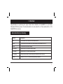
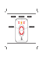
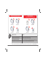
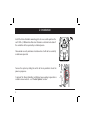
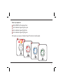
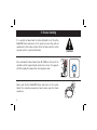
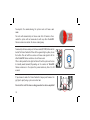
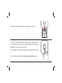
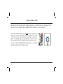
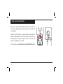
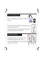
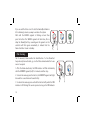
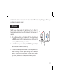
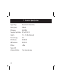
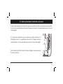
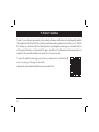
Alarm Controller
Fire and CO
Model: Ei450
Instruction Manual
Read and retain carefully for as long as the product is being used. It contains vital information on the operation and installation of your
Alarm Controller. The booklet should be regarded as part of the product.
If you are just installing the unit, the booklet must be given to the householder. The booklet is to be given to any subsequent user.
Contents
Page
1. Overview .................................................................................................................................................
3
2. Installation .............................................................................................................................................
6
3. House Coding ........................................................................................................................................
8
4. Operation ............................................................................................................................................... 13
5. Guarantee .............................................................................................................................................
18
6. Troubleshooting the RadioLINK ..................................................................................................... 19
7. Technical Specification ..................................................................................................................... 20
8. Getting your Alarm Controller Serviced ..................................................................................... 21
9. Product Updates ................................................................................................................................ 22
10. Contact Us ...........................................................................................................................................
2
24
1. Overview
Congratulations on purchasing the single button Alarm Controller for RadioLINK Fire and Carbon
Monoxide (CO) Alarm systems. The Alarm Controller tests and controls Fire, CO and combined (Fire + CO)
RadioLINK Alarm systems.
Alarm Controller functionality
Function
Description
Test
All the Alarms can be tested from a centralised location
Locate
This will silence all the Alarms in the system except the one sensing Fire or CO
Silence
This will silence the source Alarm(s)
Fire Indicator
Indicates that a Fire Alarm has been activated
CO Indicator
Indicates that a CO Alarm has been activated
EOL Indicator
Indicates that the Alarm Controller battery has reached its end of life (EOL)
Memory
Indicates if a Fire or CO Alarm has been previously activated
Memory Identification
Identifies the Alarm that has previously been activated
Some older revisions of our RadioLINK modules do not support the Memory ID function. Check the webpage or use the QR code on page 5
for a complete and accurate list of products that support this function.
3
Fire Indicator
Low Battery Indicator
Light Segments (4)
Test / Control Button
Fire / CO Alarm Controller
4
CO Indicator
Wireless Smoke Alarm System
RF Smoke Alarm
RF Smoke Alarm
rks
Wo ith
w
Wireless Smoke &
Carbon Monoxide Alarm System
RF Smoke Alarm
RF CO Alarm
Alarm Controller
Model No. - Alarms
RF Smoke Alarm
RF Smoke Alarm
Alarm Controller
Comment
Ei160RC & Ei2110 Series Smoke Alarms
The Alarms must be fitted on Ei168RC RadioLINK bases
Ei262 Mains Carbon Monoxide Alarms
The Ei262 has built-in RadioLINK technology
Ei605 & Ei650 Series Smoke Alarms
Alarms must be fitted with the correct Ei605 & Ei650 series RadioLINK module
Ei208 powered for life Carbon Monoxide Alarms
The Alarms must be fitted with Ei200MRF RadioLINK modules
Ei170RF & other RadioLINK devices
Check website for list of supported RadioLINK devices
Due to our continuous improvements policy, product performance and features are being frequently updated" - See Product Update section
5
2. Installation
Install the Alarm Controller mounting plate at an accessible point on the
wall 1.4M +/- 200mm from floor level. Consider an alternative location if
the controller will be operated by a disabled person.
6
OFF
POWER
ON
A video of the Alarm Controller installation, house coding & operation is
available on our website - see ‘Product Updates’ section.
MODE
Turn on the system by sliding the switch to the on position & check the
power up sequence.
H.CODE
Also consider security and chose a location where it will not be accidently
or otherwise operated.
Power up sequence
FIRE, BATTERY & CO indicators flash
Each individual segment lights up red
Each individual segment lights blue
Each individual segment lights green
After power up sequence all lights will go off to indicate standby mode.
7
3. House Coding
It is essential to House Code the Alarm Controller to all the other
RadioLINK Alarms and devices in the system to ensure they will not
communicate with nearby systems. Failure to house code the system
may also result in a system malfunction.
H.CODE
OFF
POWER
ON
MODE
Press and hold the House Code button (H CODE) on the back of the
controller until all segments light up blue, then release. The segments
will flash rapidly for a moment on entering house code.
WARNING
Fire / CO Alarm Controller
House code all other RadioLINK Alarms and devices in the system.
Consult the instruction manuals on how to house code the Alarms
and devices.
8
Return to the Alarm Controller and check that all segments (ring)
are flashing blue. The number of flashes should equal the number of
RadioLINK Alarms and devices in the system. A system with 3 x Smoke
Alarms, 1 x CO alarm and 1 x Alarm Controller will result in 5 blue
flashes. It may take up to 10 minutes before all 5 flashes are seen.
The flash pattern will repeat every 5 to 10 seconds while the Alarm
Controller remains in house code.
If it fails to flash the correct number of times, then consult the
‘Troubleshooting the RadioLINK’ section of this instruction manual.
Fire / CO Alarm Controller
Now, walk around the house to verify that all the other RadioLINK
Alarms and devices are giving the correct amount of flashes.
If any of these fail to flash the correct number of times, then consult
the ‘Troubleshooting the RadioLINK’ section of this instruction
manual.
9
To complete the commissioning, the system must exit house code
mode.
Do not do this until the house coding procedure has been completed!
10
OFF
POWER
ON
ON
POW
Fire / CO Alarm Controller
MODE
If you choose to make the Alarm Controller tamper proof remove the
pip (plastic post) using a pliers or similar tool.
MODE
To manually exit house code press the house code (H CODE) button on the
back of the Alarm Controller. When all the segments light up blue, release
the button. This unit will then send an exit house code signal to all the
other RadioLINK Alarms and devices to exit house code.
After a short period the blue light will turn off and the system will return
to standby mode (normal). Depending on the number of RadioLINK
Alarms and devices in the system this period could vary from 5 to 20
seconds.
H.CODE
The units will automatically exit house code after 30 minutes. Once
coded the system will not communicate with any other RadioLINK
Alarms and devices outside the house coded group.
Slide the Alarm Controller onto the mounting base on the wall.
Fire / CO Alarm Controller
Check that the RadioLINK system is working by pressing the button on
the Alarm Controller until the TEST segment lights blue. This indicates a
RadioLINK test signal has been activated.
All the Alarms in the system will sound for a short period and then stop.
Fire / CO Alarm Controller
If the test fails, consult the ‘Troubleshooting the RadioLINK’ section.
11
Reset the house code
To reset the other RadioLINK Alarms and devices in the system
consult the appropriate instruction manuals.
12
OFF
POWER
ON
MODE
To reset the Alarm Controller press and hold the house code button.
All segments will flash blue briefly and then go solid. After 5 seconds
approx. the segments will start flashing blue. At this point release
the house code button. The Alarm Controller has now been reset.
H.CODE
Sometimes in order to resolve an RF communication issue, e.g. Alarms have to be relocated, it may
necessary to reset and house code all RadioLINK Alarms and devices in the system again.
Fire / CO Alarm Controller
4. Operation
Frequent testing of the system is advised to ensure its continued and safe
operation. Guidelines and best practices for testing are as follows:
1. After the system is installed.
2. Once weekly thereafter.
3. After prolonged absence from the dwelling (.e.g. after holiday period).
4. After repair or servicing of any of the systems elements or household electrical works.
WARNING
Testing the alarm system
Press and hold the button on the Alarm Controller until the TEST
segment lights up blue. When all the alarms in the system are sounding
release the button. The alarms will stop sounding after a period and the
TEST segment will flash blue to indicate the test has been completed.
If the MEMORY segment lights up blue instead of the TEST it means
that a CO or Fire alarm was previously activated. Follow the Fire
memory or CO memory instructions in this section and report the
incident to the appropriate authorities.
Fire / CO Alarm Controller
Fire / CO Alarm Controller
13
Walk round test (optional)
Remove the Alarm Controller from its cradle. If the unit has
been tamper proofed you will need to release the latch with
a screwdriver.
With the Alarm Controller in your hand press and hold the
button. Walk around the house and verify that each Alarm is
sounding. When testing is complete release the button and
replace the controller in its cradle.
If the test fails go to ‘Troubleshooting the RadioLINK’ section.
14
Fire / CO Alarm Controller
Fire / CO Alarm Controller
When the alarm system sounds
If there is a fire, immediately evacuate the premises and telephone the
fire brigade.
If the source of the alarm is not obvious go to the Alarm Controller and check to see
which indicator is illuminated, Fire or CO.
If the CO indicator is flashing, open doors & windows while evacuating the premises.
Contact the appropriate authorities to report the incident.
Fire / CO Alarm Controller
Locate the source Alarm(s)
If the FIRE indicator is lighting and there is no obvious fire, press the
button. The LOCATE segment will change from red to blue.
After a 10 to 40 seconds period, all the Alarms in the system will stop
sounding except the source Alarm(s).
Fire / CO Alarm Controller
Fire / CO Alarm Controller
15
If you are satisfied there is no fire but the Smoke/Heat Alarm is
still continuing to alarm you may now silence the system.
Wait until the SILENCE segment is flashing red and then
press the button. The SILENCE segment will turn blue, after a
delay the Alarm(s) will stop sounding and all segments on the
controller will flash green momentarily to indicate that the
Alarm Controller is back in standby.
Fire / CO Alarm Controller
Fire / CO Alarm Controller
Fire / CO Alarm Controller
Fire Memory
The fire memory feature enables the identification of a Fire Alarm that
has previously been activated, e.g. one that false alarmed when the house
was not occupied.
1. After the Alarm deactivates, the FIRE indicator will flash alternatively
with the MEMORY segment (red) for 2 minutes and then stop.
2. To check the memory press the button, the MEMORY segment will light
blue and the source Alarm will sound briefly.
3. To recheck the memory press and hold the button briefly while the FIRE
indicator is still flashing. This can be repeated as long as the FIRE indicator
16
Fire / CO Alarm Controller
Fire / CO Alarm Controller
is flashing. If the button is not pressed within 10 seconds the FIRE indicator stops flashing, the Alarms stop
sounding and the memory is erased.
CO Memory
The CO memory feature enables the identification of a CO Alarm that
has previously been activated, e.g. a CO incident while the house was not
occupied.
1. After the Alarm deactivates, the CO indicator will flash alternatively with
the MEMORY segment (red) for 2 minutes and then stop. For the next 24h
hours they will flash alternatively once a minute.
Fire / CO Alarm Controller
Fire / CO Alarm Controller
2. To check the memory press the button, the MEMORY segment will light
blue and the source Alarm will sound briefly.
3.To recheck the memory press and hold the button briefly while the CO
indicator is flashing. This can be repeated as long as the CO memory is
flashing. If the button is not pressed within 10 seconds the CO indicator
stops flashing, the Alarms stop sounding and the memory is erased.
17
5. Guarantee
Ei Electronics guarantees this Alarm Controller for 5 years from date of purchase against any defects that
are due to faulty materials or workmanship.
This guarantee only applies to normal conditions of use and service and does not include damage resulting
from accident, neglect, misuse, unauthorised dismantling, or contamination howsoever caused. This
guarantee excludes incidental and consequential damage.
This guarantee does not cover costs associated with the removal and/or installation of units.
If the product should become defective within the guarantee period, it may be returned with proof of
purchase, carefully packaged, and with the problem clearly stated to the place of purchase or phone one
of these numbers for advice.
UK:
0870 758 4001
ROI: +353 61 471277
We shall at our discretion repair or replace the faulty unit.
18
6. Troubleshooting the RadioLINK
If, when checking the RadioLINK interconnection, some of the Alarms do not respond to the Alarm
Controller remote control test, then:
(i) Ensure the Alarm Controller has been activated correctly. Check that the power on procedure operates
as described in the ‘Installation’ section.
(ii) Repeat House Code procedure (see ‘House Coding’ section).
(iii) Relocate the Alarm Controller and/or rotate/relocate the RadioLINK Alarms. There are a number of
reasons why the RadioLINK signals may not reach all the Alarms in your system. Try rotating the Alarms
or relocating the Alarms (e.g. move them away from metal surfaces or wiring) as this can significantly
improve signal reception.
Rotating and/or relocating the Alarms may move them out of the range of existing units even though
they may have already been House Coded correctly in the system. It is therefore important to check that
all Alarms are communicating in their final installed positions. If Alarms are rotated and/or relocated,
we recommend that all Alarms are returned to the factory settings (see the respective use and care
instructions). Then House Code all Alarms again in their final positions. The RadioLINK interconnection
should then be checked again.
19
7. Technical Specification
Supply Voltage
Powered for life Lithium battery
Battery Capacity
1600 mAh
RF Frequency
868.499Mhz
Temperature Specification 0oC to 40oC (Cat 3)
Humidity
15% - 95% (Non Condensing)
Receiver Category
Cat 2
RF Performance
EN 300-220
EMC Performance
EN 301-489
RF Power+7dBm
Number of RF
interconnected Alarms
12 per house code group
20
8. Getting the Alarm Controller serviced
OFF
POWER
MODE
ON
If it needs to be returned for repair or replacement, slide the switch to the
off position, place it in a padded box and send it to “Customer Assistance
and Information” at the nearest address given on the unit or in this booklet.
H.CODE
If your Alarm Controller fails to work after you have carefully read all the instructions and checked that
the unit has been installed correctly contact Customer Assistance at the nearest address given at the end
of this booklet.
State the nature of the fault, where the Alarm Controller was purchased and
the date of purchase.
21
9. Product Updates
As part of our continuous improvement policy, product performance and features are being frequently updated.
These updates include “Works with” lists, instruction and training videos, application notes and tips, etc. To facilitate
this and keep you informed on the latest developments we have designed a product page on our website that has
all the current information on this product. This page is in addition to the information in this manual and is not
required for the successful installation and operation of your chosen product.
To access this website product page you may use your smart phone to activate the QR
code or you can go to this page on our website
www.eielectronics.com/articles/ei450-memory-id-products.html
22
Block E1
The crossed out wheelie bin symbol that is on your
product indicates that this product should not be disposed
of via the normal household waste stream. Proper
disposal will prevent possible harm to the environment or
to human health. When disposing of this product please
separate it from other waste streams to ensure that it can
be recycled in an environmentally sound manner. For
more details on collection and proper disposal, please
contact your local government office or the retailer where
you purchased this product.
0889
23
10. Contact Us
Aico Ltd
Mile End Business Park,
Maesbury Road, Oswestry,
Shropshire SY10 8NN, U.K.
Telephone: 0870 7584000
www.aico.co.uk
© Ei Electronics 2012
Ei Electronics
Shannon Industrial Estate,
Shannon, Co. Clare, Ireland.
Telephone: +353 (0)61 471277
www.eielectronics.com
P/N B17493 Rev 0