1
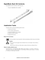
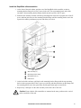
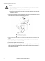
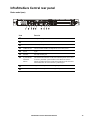
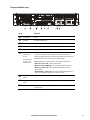
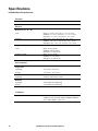
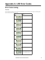
Installation Manual InfraStruXure® Central AP9465 AP9470 AP9475 This manual is available in English on the enclosed CD. Dieses Handbuch ist in Deutsch auf der beiliegenden CD-ROM verfügbar. Este manual está disponible en español en el CD-ROM adjunto. Ce manuel est disponible en français sur le CD-ROM ci-inclus. Questo manuale è disponibile in italiano nel CD-ROM allegato. 本マニュアルの日本語版は同梱の CD-ROM からご覧になれます。 O manual em Português está disponível no CD-ROM em anexo. Данное руководство на русском языке имеется на прилагаемом компакт-диске. 您可以从包含的 CD 上获得本手册的中文版本。 동봉된 CD 안에 한국어 매뉴얼이 있습니다 . Contents Product Description........................................................ 1 Overview . . . . . . . . . . . . . . . . . . . . . . . . . . . . . . . . . . . . . . . . . . . . . . . . 1 Inventory . . . . . . . . . . . . . . . . . . . . . . . . . . . . . . . . . . . . . . . . . . . . . . . 1 Receiving inspection . . . . . . . . . . . . . . . . . . . . . . . . . . . . . . . . . . . . . 1 Please recycle . . . . . . . . . . . . . . . . . . . . . . . . . . . . . . . . . . . . . . . . . . . 1 Disclaimer . . . . . . . . . . . . . . . . . . . . . . . . . . . . . . . . . . . . . . . . . . . . . . 1 Safety . . . . . . . . . . . . . . . . . . . . . . . . . . . . . . . . . . . . . . . . . . . . . . . . . . . 2 Rack-mounting safety . . . . . . . . . . . . . . . . . . . . . . . . . . . . . . . . . . . . 2 Equipment containing a battery . . . . . . . . . . . . . . . . . . . . . . . . . . . . 2 Installation ....................................................................... 3 Installation Instructions . . . . . . . . . . . . . . . . . . . . . . . . . . . . . . . . . . . . 3 Before You Begin . . . . . . . . . . . . . . . . . . . . . . . . . . . . . . . . . . . . . . . . . 3 RapidRails Rack Kit Contents . . . . . . . . . . . . . . . . . . . . . . . . . . . . . . . 4 Installation Tasks . . . . . . . . . . . . . . . . . . . . . . . . . . . . . . . . . . . . . . . . . 4 Remove the rack doors . . . . . . . . . . . . . . . . . . . . . . . . . . . . . . . . . . . 4 Select a location within the rack . . . . . . . . . . . . . . . . . . . . . . . . . . . . 4 Install the RapidRails™ slide assemblies . . . . . . . . . . . . . . . . . . . . 5 Install the system in the rack . . . . . . . . . . . . . . . . . . . . . . . . . . . . . . . 6 Replace the rack doors . . . . . . . . . . . . . . . . . . . . . . . . . . . . . . . . . . . 7 Communication Connection . . . . . . . . . . . . . . . . . . . . . . . . . . . . . . . . 7 Network overview . . . . . . . . . . . . . . . . . . . . . . . . . . . . . . . . . . . . . . . . 7 Set up the Private LAN . . . . . . . . . . . . . . . . . . . . . . . . . . . . . . . . . . . . 7 Route network cables to the InfraStruXure Central server and switch (or hub) . . . . . . . . . . . . . . . . . . . . . . . . . . . . . . . . . . . . . . . 8 Connect the InfraStruXure Central server to your Public LAN . . . . 8 Connect the InfraStruXure Central server to your Private LAN . . . 9 Apply power to the InfraStruXure Central server and switch (or hub) . . . . . . . . . . . . . . . . . . . . . . . . . . . . . . . . . . . . . . . 9 InfraStruXure Central Installation Manual i Initial Configuration....................................................... 10 Configure the InfraStruXure Central Server. . . . . . . . . . . . . . . . . . . 10 System and Web browser prerequisites . . . . . . . . . . . . . . . . . . . . . 10 Configuring the InfraStruXure Central server from a remote computer 10 Enable Remote Monitoring . . . . . . . . . . . . . . . . . . . . . . . . . . . . . . . . 11 Product Information ...................................................... 12 InfraStruXure Central Front Panel. . . . . . . . . . . . . . . . . . . . . . . . . . . 12 Basic model (front) . . . . . . . . . . . . . . . . . . . . . . . . . . . . . . . . . . . . . . 12 Standard model (front) . . . . . . . . . . . . . . . . . . . . . . . . . . . . . . . . . . . 13 Enterprise model (front) . . . . . . . . . . . . . . . . . . . . . . . . . . . . . . . . . . 14 InfraStruXure Central rear panel . . . . . . . . . . . . . . . . . . . . . . . . . . . . 15 Basic model (rear) . . . . . . . . . . . . . . . . . . . . . . . . . . . . . . . . . . . . . . . 15 Standard Model (rear) . . . . . . . . . . . . . . . . . . . . . . . . . . . . . . . . . . . . 16 Enterprise Model (rear) . . . . . . . . . . . . . . . . . . . . . . . . . . . . . . . . . . . 17 Specifications . . . . . . . . . . . . . . . . . . . . . . . . . . . . . . . . . . . . . . . . . . . 18 InfraStruXure Central server . . . . . . . . . . . . . . . . . . . . . . . . . . . . . . 18 Appendix A: LED Error Codes .................................... 19 Error Code Listing . . . . . . . . . . . . . . . . . . . . . . . . . . . . . . . . . . . . . . . 19 Overview . . . . . . . . . . . . . . . . . . . . . . . . . . . . . . . . . . . . . . . . . . . . . . . 19 Appendix B: Diagnostic Messages.............................. 21 Message Listing . . . . . . . . . . . . . . . . . . . . . . . . . . . . . . . . . . . . . . . . . 21 Overview . . . . . . . . . . . . . . . . . . . . . . . . . . . . . . . . . . . . . . . . . . . . . . . 21 Warranties and Policies ................................................ 24 Two-Year Factory Warranty . . . . . . . . . . . . . . . . . . . . . . . . . . . . . . . . 24 Terms of warranty . . . . . . . . . . . . . . . . . . . . . . . . . . . . . . . . . . . . . . . 24 Non-transferable warranty . . . . . . . . . . . . . . . . . . . . . . . . . . . . . . . . 24 Exclusions . . . . . . . . . . . . . . . . . . . . . . . . . . . . . . . . . . . . . . . . . . . . . 24 Warranty claims . . . . . . . . . . . . . . . . . . . . . . . . . . . . . . . . . . . . . . . . . 25 Life Support Policy . . . . . . . . . . . . . . . . . . . . . . . . . . . . . . . . . . . . . . . 25 General policy . . . . . . . . . . . . . . . . . . . . . . . . . . . . . . . . . . . . . . . . . . 25 Examples of life-support devices . . . . . . . . . . . . . . . . . . . . . . . . . . 25 ii InfraStruXure Central Installation Manual Product Description Overview Inventory • APC ® InfraStruXure™ Central server—A 1U or 2U management device. The InfraStruXure Central server works with your APC devices, NetBotz appliances, and other third-party SNMP devices to provide a comprehensive monitoring solution for your IT environment and equipment. The InfraStruXure Central appliance is available in Basic, Standard, or Enterprise models. • Rack-mount rails— RapidRails™ used to install the InfraStruXure Central server in a standard, 19-inch (482 mm) enclosure or rack. • Power Cords —NEMA 5-15P to IEC-320-C13 and an IEC-320-C13 to IEC-320-C14 power cord. Use the cord appropriate for your power distribution. Note: The Enterprise model of the InfraStruXure Central server device comes with two of each cable. • The InfraStruXure Central Installation Manual (this book) Receiving inspection Inspect the package and contents for shipping damage, and make sure that all parts were sent. Report any damage immediately to the shipping agent. Report missing contents, damage, or other problems immediately to APC or your APC reseller. Please recycle The shipping materials are recyclable. Please save them for later use, or dispose of them appropriately. Disclaimer APC is not responsible for damage sustained during reshipment of this product from a reseller. InfraStruXure Central Installation Manual 1 Safety Rack-mounting safety The InfraStruXure Central server is shipped with rack-mounting rails. Install the rails at the appropriate position in your rack, and mount the unit. If the unit is mounted in an enclosure instead of an open rack, the maximum ambient temperature in the enclosure should be no greater than 35°C (95°F). • When you install equipment in the rack, make sure it does not interfere with the air flow required for safe operation for the equipment. • When you mount equipment in the rack, make sure you do not cause a hazardous condition because of an uneven mechanical load. • When you connect equipment to the supply circuit, avoid overloading the circuits, which could jeopardize over-current protection and damage the supply wiring. See ratings on the equipment nameplates for guidance. • Maintain reliable earth grounding of the unit, particularly for supply connections (e.g., when Power Distribution Units (PDUs) that are not directly connected to the branch circuit are used). Equipment containing a battery This equipment contains a non-replaceable lithium coin cell battery. 2 InfraStruXure Central Installation Manual Installation Installation Instructions This installation guide provides instructions for trained service technicians installing one or more systems in a rack. The provided RapidRails rack kit can be installed without tools in any enclosure that has square holes. One rack kit is required for each system installed in the rack. VersaRails™ rack kits, which are designed for use with enclosures that have round holes, are available for purchase separately. Caution: Do not install rack kit components designed for another system. Use only the rack kit for your system. Using the rack kit for another system may result in damage to the system and personal injury to yourself and to others. Before You Begin Before you begin installing your system in the rack, read the safety instructions on page 2 and in this section. Observe the following safety precautions when installing your system in the rack Caution: • When installing multiple systems in a rack, complete all of the procedures for the current system before attempting to install the next system. • Follow the procedures in this document to protect yourself as well as other service technicians. Your system is very large and heavy, and proper preparation and planning are important to prevent injury to yourself and to others, especially when systems are installed in the top half of the rack. • Installing systems in a rack without front and side stabilizer feet could cause the rack to tip over, potentially resulting in bodily injury. Always install the stabilizer feet of the rack before installing components. The stabilizer feet help prevent the rack from tipping over when a system or other component is pulled out of the rack with the slide assemblies fully extended. See the documentation provided with the rack cabinet for instructions on installing and anchoring the stabilizer feet. • After installing systems in a rack, never pull more than one system out of the rack on its slide assemblies at one time. The weight of more than one extended system could cause the rack to tip over and cause injury. InfraStruXure Central Installation Manual 3 RapidRails Rack Kit Contents The RapidRails rack kit includes the following items: • One pair of RapidRails slide assemblies Installation Tasks To install a rack kit, perform the following tasks in order: 1. Remove the rack doors. 2. Select a location within the rack. 3. Install the RapidRails slide assemblies. 4. Install the system in the rack. 5. Replace the rack doors. Remove the rack doors See the procedures for removing doors in the documentation provided with your rack cabinet. Caution: • Due to the size and weight of the rack cabinet doors, never attempt to remove them by yourself. • Store the doors where they will not injure someone if the doors accidently fall over. Select a location within the rack Each InfraStruXure Central Standard or Basic Edition system requires 1 U (44 mm [1.75 inches]) of vertical space in the rack. Each InfraStruXure Central Enterprise Edition system requires 2 U (88 mm [3.5 inches]) of vertical space in the rack. 4 InfraStruXure Central Installation Manual Install the RapidRails slide assemblies 1. At the front of the rack cabinet, position one of the RapidRails slide assemblies so that its mounting-bracket flange fits in one U-space in the rack. The top mounting hook on the slide assembly’s front mounting bracket flange should enter the top hole of the U-space. 2. Push the slide assembly forward until the top mounting hook enters the top square hole of the Uspace, and then push down on the mounting-bracket flange until the mounting hooks seat in the square holes and the push button pops out and clicks (see below). Slide assembly (2) Mounting bracket flange Mounting hooks (2) Push button 3. At the back of the enclosure, pull back on the mounting-bracket flange until the top mounting hook is in the top square hole of the U-space you selected, and then push down on the flange until the mounting hooks seat in the square holes and the push button pops out and clicks. 4. Repeat steps 1 through 3 for the slide assembly on the other side of the rack. Caution: Ensure that the slide assemblies are mounted at the same position on the vertical rails on each side of the rack. InfraStruXure Central Installation Manual 5 Install the system in the rack Caution: • If you are installing more than one system, install the first system in the lowest available position in the rack. • Never pull more than one component out of the rack at a time. • Because of the size and weight of the system, never attempt to install the system in the slide assemblies by yourself. 1. Pull the two slide assemblies out of the rack until they lock in the fully extended position. Lift the system into position in front of the extended slides (see below). shoulder screw on system system locking mechanism 2. Place one hand on the front-bottom of the system and the other hand on the back-bottom of the system. 3. Tilt the back of the system down while aligning the back shoulder screws on the sides of the system with the back slots on the slide assemblies. 4. Engage the back shoulder screws into their slots. 5. Lower the front of the system and engage the front and middle shoulder screws in their slots (the middle slot is just behind the yellow system release latch). When all shoulder screws are properly seated, the system locking mechanism at the front of each slide assembly clicks and locks the system into the slide assembly. 6 InfraStruXure Central Installation Manual 6. Press up on the slide release latch at the side of each slide to slide the system completely into the rack. 7. Push in and turn the captive thumbscrews on each side of the front chassis panel to secure the system to the rack. To remove the system from the slide assemblies, press down on the thumbpads of the system locking mechanism, and then pull the system forward. Replace the rack doors See the procedures for replacing doors in the documentation provided with your rack. Caution: Because of the size and weight of the rack cabinet doors, never attempt to remove or install them by yourself. Communication Connection Network overview The InfraStruXure Central server provides for the management of networked APC devices, NetBotz appliances, and other third-party SNMP devices. It connects to both your existing network (Public LAN) and a private network (Private LAN) to manage connected devices. Set up the Private LAN Connect a CAT-5 network cable to the network port on each SNMP device The InfraStruXure Central server can manage any APC device with a network port, as well as third-party SNMP devices. Note: If you are running PowerChute® Network Shutdown software with an InfraStruXure system’s UPS, that UPS must be connected to the public network. InfraStruXure Central Installation Manual 7 Route network cables to the InfraStruXure Central server and switch (or hub) Overhead routing. This section is for InfraStruXure system installations. 1. Ensure that the APC Shielding Partitions and Cable Ladders are installed on the NetShelter enclosures and the InfraStruXure PDUs. 2. Run the Cat-5 network cables (provided) from each APC device to the switch (or hub) a. Start with the device farthest from the switch (or hub) that uses the longest CAT-5 network cable. b. Bundle cables together and route the bundles in the data cable troughs along rows and across ladders, if necessary. 3. Connect each APC device’s network cable to any available port on the switch (or hub). Install and route data cables (alternative routing). Note: If possible, route data cables overhead, as described in “Overhead routing” on this page. Using APC Shielding Partitions and Cable Ladders with your InfraStruXure system reduces problems related to induced voltages for data transmission. If you must route data cables under a raised floor: • Do not route data cables inside an InfraStruXure PDU to the floor, either within the power cable conduit or in any other location. Induced voltages from the power cables may interfere with data transmission. Route data cables out the roof of the InfraStruXure PDU and down inside the first NetShelter enclosure to the floor. • Induced voltages can also create problems under the floor when data cables are too close to any power cables. Even if data transmission is successful after the initial installation, later additions to power cabling under the floor for other equipment in your data center can jeopardize the integrity of the data transmission for your InfraStruXure Central system. 8 InfraStruXure Central Installation Manual Connect the InfraStruXure Central server to your Public LAN For InfraStruXure system installations, connect the InfraStruXure Central server’s Gb1 port (Standard version shown) to any network port on the user’s Public LAN, using a network jumper cable, or a standard network cable, if necessary. . Public LAN connection: Connect the InfraStruXure Central server to your Private LAN 1. Connect a port on your Private LAN to the InfraStruXure Central server’s Gb2 port (Standard version shown). As indicated by the label that covers the Gb2 port, do not connect any network other than your Private LAN to that port, or to any switch that connects to that port. Private LAN Connection: 2. To access the Private LAN (port Gb2), see “Initial Configuration” on page 10. Apply power to the InfraStruXure Central server and switch (or hub) After you install the InfraStruXure Central server and switch (or hub) and make all of the communication connections, connect the power cords to a Rack PDU within the enclosure to apply power to the InfraStruXure Central server. InfraStruXure Central Installation Manual 9 Initial Configuration Configure the InfraStruXure Central Server To configure the public LAN network settings on the InfraStruXure Central server for the first time, you must connect to the InfraStruXure Central server as follows: • Connect the private network port (Gb2) with a computer connected directly to the Gb2 port or connected to a switch (or hub) that is connected to the Gb2 port. . System and Web browser prerequisites The InfraStruXure Central console is a stand-alone Java application that runs on systems that meet the following requirements: • A PC with a 1 GHz or better AMD/Intel processor running Microsoft® Windows® (2000 SP4, XP SP2, Server 2003, or Vista) or Red Hat Enterprise Linux 5.x (32-bit platforms only) • 512MB RAM • A screen resolution of at least 1024x768. Configuring the InfraStruXure Central server from a remote computer 1. Connect a computer to a network port on the private switch (or hub), or directly to the Gb2 port if a switch (or hub) is unavailable. The computer must meet the following requirements: – It must be configured to obtain an IP address automatically (through DHCP). – It must be running TCP/IP as a network protocol. – The browser must be JavaScript® enabled: • Mozilla Firefox® version 1.5.0.6 or higher • Netscape Navigator version 8.2 • Microsoft Internet Explorer® version 7.0 2. Release and renew your computer’s IP address to assign it an address on the Private LAN. 3. Open the browser, and enter the LAN IP address for the InfraStruXure Central server. 4. Use 192.168.1.1 as the default IP address for InfraStruXure Central on the LAN. 5. Download and install the InfraStruXure Central Client from the displayed Web page. 6. Double-click the ISX Central Client icon to display the InfraStruXure Central Logon dialog. 7. When the InfraStruXure Central Logon display appears, use apc (lowercase) for both the username and password, and click OK. 8. After the client starts, select the Settings menu and select Server Administration Settings. 9. In the displayed sub-menu, select Network Settings. 10.On the Public tab of the Network Settings display, enter the necessary information about the InfraStruXure Central server. This information can be provided by your network administrator. 11. When you are finished, click Apply and then OK. 10 InfraStruXure Central Installation Manual Enable Remote Monitoring APC can remotely monitor your InfraStruXure Central server and the devices it manages, and notify you of events via e-mail, pager, or phone. If you decide to use APC’s Remote Monitoring Service (RMS), follow these steps:. Warning: Information that will be sent to the APC monitoring service must be entered in English. Any other language may prevent RMS from being able to properly notify of or describe any critical issues. 1. From the Settings menu, select Server Administration Settings. 2. In the Server Administration Settings sub-menu, click the Remote Monitoring entry. 3. In the APC Remote Monitoring Service display, click Registration Settings. 4. If you have not registered for RMS: a. In the Choose RMS Settings Type display, select New Customer and click Next. b. In the RMS Contact Information display, fill in all of the required fields and click Next. c. In the RMS Company Information display, fill in all of the required fields and click Finish. 5. If you have previously registered for RMS: a. In the Choose RMS Settings Type display, select Existing Customer and click Next. b. In the RMS Logon Settings display, fill in your e-mail address and password, then click Next. c. In the RMS Contact Information display, verify that the displayed information is correct and click Next. d. In the RMS Company Information display, verify that the information is correct and click Finish. 6. Visit http://rms.apc.com to complete the RMS configuration. On the RMS page, click Contact Us to obtain the phone number to call and complete the activation process. InfraStruXure Central Installation Manual 11 Product Information InfraStruXure Central Front Panel Basic model (front) Item Function Diagnostic Indicators The four diagnostics indicators on the system front panel display error codes during system startup. Power-on Indicator, Power Button The power-on indicator lights when the system power is on. The power-on indicator blinks when the system is not turned on but power is available. The power button controls the power supply output to the system. NMI button The NMI button is used to troubleshoot software and device driver errors when using certain operating systems. This button can be pressed using the end of a paper clip. Use this button only if directed to do so by qualified support personnel. USB Ports (2) Used to connect USB 2.0-compliant devices to the system. HDD LED Hard disk drive LED. When this LED is amber, the disk is being accessed. Monitor VGA monitor port System Identification Button The identification buttons on the front and back panels can be used to locate a particular system within a rack. When one of these buttons is pushed, the blue system status indicator on the front and back blinks until one of the buttons is pushed again. Blue and Amber System Status Indicator LEDs 12 LEDs illuminate as described below to indicate system status: • Blue Off, Amber Off: System is turned off. • Blue Off, Amber Blinking: The system has detected an error. • Blue On, Amber Off: Power is turned on, system is operational. • Blue Blinking, Amber Off: The system identification indicator has been activated to identify the system in a rack. InfraStruXure Central Installation Manual Standard model (front) Item Function DVD Drive Allows CD/DVD-based updates for software and firmware. (Not available on the Basic model) Diagnostic Indicators The four diagnostics indicators on the system front panel display error codes during system startup. Power-on Indicator, Power Button The power-on indicator lights when the system power is on. The power-on indicator blinks when the system is not turned on but power is available. The power button controls the power supply output to the system. NMI button The NMI button is used to troubleshoot software and device driver errors when using certain operating systems. This button can be pressed using the end of a paper clip. Use this button only if directed to do so by qualified support personnel. USB Ports (2) Used to connect USB 2.0-compliant devices to the system. HDD LED Hard disk drive LED. When this LED is amber, the disk is being accessed. Monitor VGA monitor port. System Identification Button The identification buttons on the front and back panels can be used to locate a particular system within a rack. When one of these buttons is pushed, the blue system status indicator on the front and back blinks until one of the buttons is pushed again. InfraStruXure Central Installation Manual 13 Enterprise model (front) Item Function Power-on Indicator, Power Button The power-on indicator lights when the system power is on. The power-on indicator blinks when the system is not turned on but power is available. The power button controls the power supply output to the system. NMI Button Used to troubleshoot software and device driver errors when using certain operating systems. This button can be pressed using the end of a paper clip. Use this button only if directed to do so by qualified support personnel or by the operating system's documentation. System Identification Button The identification buttons on the front and back panels can be used to locate a particular system within a rack. When one of these buttons is pushed, the blue system status indicator on the front and back blinks until one of the buttons is pushed again. LCD Display (Enterprise only) Provides system ID, status information, and system error messages. The LCD display is illuminated with a blue light during normal system operation. If the system needs attention due to a problem with power supplies, fans, system temperature, or hard drives, the LCD display will be illuminated with amber light. Note: If the system is connected to AC power and an error has been detected, the LCD display flashes amber regardless of whether the system is turned on. 14 USB Ports (2) Used to connect USB 2.0-compliant devices to the system. Monitor VGA monitor port DVD Drive Allows CD/DVD-based updates for software and firmware. (Not available on the Basic model.) InfraStruXure Central Installation Manual InfraStruXure Central rear panel Basic model (rear) Item Function Power Socket Receptacle for power cord. Mouse PS/2 Mouse port Kbd PS/2 Keyboard port USB Ports (2) Used to connect USB 2.0-compliant devices to the system. Serial 9-pin Monitor External monitor port System Status LED and button The identification buttons on the front and back panels can be used to locate a particular system within a rack. When one of these buttons is pushed, the blue system status indicator on the front and back blinks until one of the buttons is pushed again. Gb1 Gigabit Ethernet port for connecting to a public LAN. Gb2 Gigabit Ethernet port for connecting to the private LAN. InfraStruXure Central Installation Manual 15 Standard Model (rear) Item 16 Function Power Socket Receptacle for power cord. Mouse PS/2 Mouse port Keyboard PS/2 Keyboard port USB Ports (2) Used to connect USB 2.0-compliant devices to the system. Serial Port 9-pin Monitor VGA monitor port System Status LED and button The identification buttons on the front and back panels can be used to locate a particular system within a rack. When one of these buttons is pushed, the blue system status indicator on the front and back blinks until one of the buttons is pushed again. Gb2 Gigabit Ethernet port for connecting to the private LAN. Gb1 Gigabit Ethernet port for connecting to a public LAN. InfraStruXure Central Installation Manual Enterprise Model (rear) Item Function Serial Port 9-pin Monitor External monitor port USB Ports (2) Used to connect USB 2.0-compliant devices to the system. Gb1 Gigabit Ethernet port for connecting to the public LAN. Gb2 Gigabit Ethernet port for connecting to a private LAN. System Identification Button The identification buttons on the front and back panels can be used to locate a particular system within a rack. When one of these buttons is pushed, the blue system status indicator on the front and back blinks until one of the buttons is pushed again. Blue and Amber System Status Indicator LEDs LEDs illuminate as described below to indicate system status: • Blue Off, Amber Off: System is turned off. • Blue Off, Amber Blinking: The system has detected an error. • Blue On, Amber Off: Power is turned on and the system is operational. • Blue Blinking, Amber Off: The system identification indicator has been activated to identify the system in a rack. Power supply status A green LED indicates that the power supply is operational Power supply fault An amber LED indicates a problem with the power supply. AC line status A green LED indicates that a valid AC source is connected to the power supply. InfraStruXure Central Installation Manual 17 Specifications InfraStruXure Central server Electrical Input 100–240 VAC; 50/60 Hz; 0.7 A to 0.5 A Physical Dimensions (H × W × D) Unit Shipping Basic: 4.5 × 48.3 × 54.6 cm (1.7 × 19 × 21.5 in) Standard: 4.5 × 48.3 × 54.6 cm (1.7 × 19 × 21.5 in) Enterprise: 7.6 × 48.3 × 68.6 cm (3 × 19 × 27 in) Basic: 30.5 × 63.5 × 88.9 cm (12 × 25 × 35 in) Standard: 30.5 × 63.5 × 88.9 cm (12 × 25 × 35 in) Enterprise: 38.1 × 63.5 × 91.4 cm (15 × 25 × 36 in) Weight Unit Shipping weight Basic: 11.8 kg (26 lb) Standard: 20.4 kg (45 lb) Enterprise: 37.2 kg (82 lb) Basic: 13.2 kg (29 lb) Standard: 21.7 kg (48 lb) Enterprise: 38.6 kg (85 lb) Environmental Temperature Operating Storage 50 to 95 °F (10 to 35°C) 5 to 122°F (–15 to 50°C) Elevation Operating 10 000 ft (3000 m) above MSL Humidity Operating Storage 20-80% RH, non-condensing 5–95% RH, non-condensing Compliance Approvals 18 UL, CE, FCC, CSA, ICES-003, IRAM, NOM, CE CISPR 22, TUV-GS, SAB, GOST, NEMKO, SPRING, VCCI, MIC, BSMI, C-Tick, CCC InfraStruXure Central Installation Manual Appendix A: LED Error Codes Error Code Listing Overview The four diagnostics indicators on the system front panel display error codes during system startup. The following table lists the causes associated with these codes. Code Causes Possible processor failure. Memory failure. Possible expansion card failure. Possible video card failure. Hard drive failure. Possible USB failure. No memory modules detected. System board failure. Memory configuration error. Possible system board resource and/or system board hardware failure. InfraStruXure Central Installation Manual 19 Possible expansion card failure. Other failure. The system is in a normal operating condition after POST. 20 InfraStruXure Central Installation Manual Appendix B: Diagnostic Messages Message Listing Overview The system's control panel LCD provides status messages to signify when the system is operating correctly or when the system needs attention. The LCD lights blue to indicate a normal operating condition, and lights amber to indicate an error condition. The LCD scrolls a message that includes a status code followed by descriptive text.. The following table lists the potential error messages along with a short description of the condition described by the message. Code Text Causes N/A SYSTEM NAME The SYSTEM NAME displays under the following conditions: • The system is turned on. • The power is off and active POST errors are displayed. E1000 FAILSAFE, Call Support Contact APC Customer Support at a number on the back cover of this manual E1114 Temp Ambient Ambient system temperature is out of acceptable range. E1116 Temp Memory Memory has exceeded acceptable temperature and has been disabled to prevent damage to the components. E12nn xx PwrGd Specified voltage regulator has failed. E1210 CMOS Batt CMOS battery is missing, or the voltage is out of acceptable range. E1211 ROMB Batt RAID battery is either missing, bad, or unable to recharge due to thermal issues. E1229 CPU # VCORE Processor # VCORE voltage regulator has failed. E1310 RPM Fan ## RPM of specified cooling fan is out of acceptable operating range. E1313 Fan Redundancy The system is no longer fan-redundant. Another fan failure will put the system at risk of over-heating. E1410 CPU # IERR Specified microprocessor is reporting an internal error. E1414 CPU # Thermtrip Specified microprocessor is out of acceptable temperature range and has halted operation. E1418 CPU # Presence Specified processor is missing or bad, and the system is in an unsupported configuration. E141C CPU Mismatch Processors are in a configuration unsupported by APC. E141F CPU Protocol The system BIOS has reported a processor protocol error. E1420 CPU Bus PERR The system BIOS has reported a processor bus parity error. E1421 CPU Init The system BIOS has reported a processor initialization error. E1422 CPU Machine Chk The system BIOS has reported a machine check error. E1610 PS # Missing No power is available from the specified power supply; specified power supply is improperly installed or faulty. E1614 PS # Status No power is available from the specified power supply; specified power supply is improperly installed or faulty. InfraStruXure Central Installation Manual 21 E1618 PS # Predictive Power supply voltage is out of acceptable range; specified power supply is improperly installed or faulty. E161C PS # Input Lost Power source for specified power supply is unavailable, or out of acceptable range. E1620 PS # Input Range Power source for specified power supply is unavailable, or out of acceptable range. E1624 PS Redundancy The power supply subsystem is no longer redundant. If the last supply fails, the system will go down. E1710 I/O Channel Chk The system BIOS has reported an I/O channel check. E1711 PCI PERR B## D## F## The system BIOS has reported a PCI parity error on a PCI PERR Slot # component that resides in PCI configuration space at bus ##, device ##, function ##. The system BIOS has reported a PCI parity error on a component that resides in the specified PCI slot. E1712 PCI SERR B## D## F## The system BIOS has reported a PCI system error on a PCI SERR Slot # component that resides in PCI configuration space at bus ##, device ##, function ##. The system BIOS has reported a PCI system error on a component that resides in the specified slot. The system BIOS has determined that there has been an error in the system, but is unable to determine its origin. E1714 Unknown Err E171F PCIE Fatal Err B## The system BIOS has reported a PCIe fatal error on a D## F## component that resides in PCI configuration space at bus ##, PCIE Fatal Err Slot # device ##, function ##. The system BIOS has reported a PCIe fatal error on a component that resides in the specified slot. 22 E1810 HDD ## Fault The SAS subsystem has determined that hard drive ## has experienced a fault. E1811 HDD ## Rbld Abrt The specified hard drive has experienced a rebuild abort. E1812 HDD ## Removed The specified hard drive has been removed from the system. E1913 CPU & Firmware Mismatch The BMC firmware does not support the CPU. E1A11 PCI Rsr Config PCI risers are not configured correctly; some invalid configurations may prevent the system from turning on. E1A12 PCI Rsr Missing One or all of the PCI risers are missing, preventing the system from turning on. E1A14 SAS Cable A SAS cable A is missing or bad. E1A15 SAS Cable B SAS cable B is missing or bad. E2010 No Memory No memory is installed in the system. E2011 Mem Config Err Memory detected, but is not configurable. Error detected during memory configuration. E2012 Unusable Memory Memory is configured, but not usable. Memory subsystem failure. E2013 Shadow BIOS Fail The system BIOS failed to copy its flash image into memory. E2014 CMOS Fail CMOS failure. CMOS RAM not functioning properly. E2015 DMA Controller DMA controller failure. E2016 Int Controller Interrupt controller failure. InfraStruXure Central Installation Manual E2017 Timer Fail Timer refresh failure. E2018 Prog Timer Programmable interval timer error. E2019 Parity Error Parity error. E201A SIO Err SIO failure. E201B Kybd Controller Keyboard controller failure. E201C SMI Init System management interrupt (SMI) initialization failure. E201D Shutdown Test BIOS shutdown test failure. E201E POST Mem Test BIOS POST memory test failure. E201F DRAC Config Dell remote access controller (DRAC) configuration failure. E2020 CPU Config CPU configuration failure. E2021 Memory Population Incorrect memory configuration. Memory population order incorrect. E2022 POST Fail General failure after video. E2110 MBE Crd # DIMM ## & ## One of the DIMMs in the set implicated by "## & ##" has had a memory multi-bit error (MBE). If no memory card is present, the "Crd #" string is left out of the message. E2111 SBE Log Disable Crd # The system BIOS has disabled memory single-bit error (SBE) DIMM ## logging, and will not resume logging further SBEs until the system is rebooted. "##" represents the DIMM implicated by the BIOS. If no memory riser card is present, the "Crd #" string is left out of the message. E2112 Mem Spare Crd # DIMM The system BIOS has spared the memory because it has ## determined that the memory had too many errors. "## & ##" represents the DIMM pair implicated by the BIOS. If no memory card is present, the "Crd #" string is left out of the message. E2113 Mem Mirror Crd # DIMM The system BIOS has disabled memory mirroring because it has ## & ## determined that one half of the mirror has had too many errors. "## & ##" represents the DIMM pair implicated by the BIOS. If no memory card is present, the "Crd #" string is left out of the message. E2118 Fatal NB Mem CRC One of the connections in the Fully Buffered DIMM (FBD) memory subsystem link on the Northbound side has failed. E2119 Fatal SB Mem CRC One of the connections in the FBD memory subsystem link on the Southbound side has failed. I1910 Intrusion System cover has been removed. I1911 >3 ERRs Chk Log LCD overflow message. A maximum of three error messages can display sequentially on the LCD. The fourth message displays as the standard overflow message. I1912 SEL Full System Event Log is full of events, and is unable to log any more events. W1228 ROMB Batt < 24hr Warns predictively that the RAID battery has less than 24 hours of charge left. InfraStruXure Central Installation Manual 23 Warranties and Policies Two-Year Factory Warranty This warranty applies only to the products you purchase for your use in accordance with this manual. Terms of warranty APC warrants its products to be free from defects in materials and workmanship for a period of two years from the date of purchase. APC will repair or replace defective products covered by this warranty. This warranty does not apply to equipment that has been damaged by accident, negligence or misapplication or has been altered or modified in any way. Repair or replacement of a defective product or part thereof does not extend the original warranty period. Any parts furnished under this warranty may be new or factory-remanufactured. Non-transferable warranty This warranty extends only to the original purchaser who must have properly registered the product. The product may be registered at the APC Web site, www.apc.com. Exclusions APC shall not be liable under the warranty if its testing and examination disclose that the alleged defect in the product does not exist or was caused by end user’s or any third person’s misuse, negligence, improper installation or testing. Further, APC shall not be liable under the warranty for unauthorized attempts to repair or modify wrong or inadequate electrical voltage or connection, inappropriate on-site operation conditions, corrosive atmosphere, repair, installation, exposure to the elements, Acts of God, fire, theft, or installation contrary to APC recommendations or specifications or in any event if the APC serial number has been altered, defaced, or removed, or any other cause beyond the range of the intended use. THERE ARE NO WARRANTIES, EXPRESS OR IMPLIED, BY OPERATION OF LAW OR OTHERWISE, OF PRODUCTS SOLD, SERVICED OR FURNISHED UNDER THIS AGREEMENT OR IN CONNECTION HEREWITH. APC DISCLAIMS ALL IMPLIED WARRANTIES OF MERCHANTABILITY, SATISFACTION AND FITNESS FOR A PARTICULAR PURPOSE. APC EXPRESS WARRANTIES WILL NOT BE ENLARGED, DIMINISHED, OR AFFECTED BY AND NO OBLIGATION OR LIABILITY WILL ARISE OUT OF, APC RENDERING OF TECHNICAL OR OTHER ADVICE OR SERVICE IN CONNECTION WITH THE PRODUCTS. THE FOREGOING WARRANTIES AND REMEDIES ARE EXCLUSIVE AND IN LIEU OF ALL OTHER WARRANTIES AND REMEDIES. THE WARRANTIES SET FORTH ABOVE CONSTITUTE APC’S SOLE LIABILITY AND PURCHASER’S EXCLUSIVE REMEDY FOR ANY BREACH OF SUCH WARRANTIES. APC WARRANTIES EXTEND ONLY TO PURCHASER AND ARE NOT EXTENDED TO ANY THIRD PARTIES. 24 InfraStruXure Central Installation Manual IN NO EVENT SHALL APC, ITS OFFICERS, DIRECTORS, AFFILIATES OR EMPLOYEES BE LIABLE FOR ANY FORM OF INDIRECT, SPECIAL, CONSEQUENTIAL OR PUNITIVE DAMAGES, ARISING OUT OF THE USE, SERVICE OR INSTALLATION, OF THE PRODUCTS, WHETHER SUCH DAMAGES ARISE IN CONTRACT OR TORT, IRRESPECTIVE OF FAULT, NEGLIGENCE OR STRICT LIABILITY OR WHETHER APC HAS BEEN ADVISED IN ADVANCE OF THE POSSIBILITY OF SUCH DAMAGES. SPECIFICALLY, APC IS NOT LIABLE FOR ANY COSTS, SUCH AS LOST PROFITS OR REVENUE, LOSS OF EQUIPMENT, LOSS OF USE OF EQUIPMENT, LOSS OF SOFTWARE, LOSS OF DATA, COSTS OF SUBSTITUENTS, CLAIMS BY THIRD PARTIES, OR OTHERWISE. NO SALESMAN, EMPLOYEE OR AGENT OF APC IS AUTHORIZED TO ADD TO OR VARY THE TERMS OF THIS WARRANTY. WARRANTY TERMS MAY BE MODIFIED, IF AT ALL, ONLY IN WRITING SIGNED BY AN APC OFFICER AND LEGAL DEPARTMENT. Warranty claims Customers with warranty claims issues may access the APC customer support network through the Support page of the APC Web site, www.apc.com/support. Select your country from the country selection pull-down menu at the top of the Web page. Select the Support tab to obtain contact information for customer support in your region. Life Support Policy General policy American Power Conversion (APC) does not recommend the use of any of its products in the following situations: • In life-support applications where failure or malfunction of the APC product can be reasonably expected to cause failure of the life-support device or to affect significantly its safety or effectiveness. • In direct patient care. APC will not knowingly sell its products for use in such applications unless it receives in writing assurances satisfactory to APC that (a) the risks of injury or damage have been minimized, (b) the customer assumes all such risks, and (c) the liability of APC is adequately protected under the circumstances. Examples of life-support devices The term life-support device includes but is not limited to neonatal oxygen analyzers, nerve stimulators (whether used for anesthesia, pain relief, or other purposes), autotransfusion devices, blood pumps, defibrillators, arrhythmia detectors and alarms, pacemakers, hemodialysis systems, peritoneal dialysis systems, neonatal ventilator incubators, ventilators (for adults and infants), anesthesia ventilators, infusion pumps, and any other devices designated as “critical” by the U.S. FDA. InfraStruXure Central Installation Manual 25 Hospital-grade wiring devices and leakage current protection may be ordered as options on many APC UPS systems. APC does not claim that units with these modifications are certified or listed as hospitalgrade by APC or any other organization. Therefore these units do not meet the requirements for use in direct patient care. 26 InfraStruXure Central Installation Manual APC Worldwide Customer Support Customer support for this or any other APC product is available at no charge in any of the following ways: • Visit the APC Web site to access documents in the APC Knowledge Base and to submit customer support requests. – www.apc.com (Corporate Headquarters) Connect to localized APC Web sites for specific countries, each of which provides customer support information. – www.apc.com/support/ Global support searching APC Knowledge Base and using e-support. • Contact an APC Customer Support center by telephone or e-mail. – Regional centers Direct InfraStruXure Customer Support Line (1)(877)537-0607 (toll free) APC headquarters U.S., (1)(800)800-4272 Canada (toll free) Latin America (1)(401)789-5735 (USA) Europe, Middle East, Africa (353)(91)702000 (Ireland) Western Europe +800 0272 0272 (including Scandinavia) Japan (0) 36402-2001 Australia 1(800) 652 725 (toll free) New Zealand 0 (800) 333 373 (toll free) – Local, country-specific centers: go to www.apc.com/support/contact for contact information. Contact the APC representative or other distributor from whom you purchased your APC product for information on how to obtain local customer support. Entire contents copyright 2008 American Power Conversion Corporation. All rights reserved. Reproduction in whole or in part without permission is prohibited. APC, the APC logo, NetShelter, PowerChute, and InfraStruXure are trademarks of American Power Conversion Corporation. All other trademarks, product names, and corporate names are the property of their respective owners and are used for informational purposes only. 990-3321-001 *990-1636D-001* 06/2008