1
OWNER’S
M A N UA L
AND
O P E R AT I N G
I N S T RU C T I O N S
Proudly
Manufactured in the U.S.A. by
Pyro Industries, Inc. Burlington, WA 98233
Congratulations on the purchase of your Whitfield Quest Pellet Stove!
When you purchased your Whitfield stove, you joined the ranks of thousands of concerned
individuals whose answer to their home heating system reflects their concern for aesthetics,
efficiency and our environment.
We extend our continued support to help you achieve the maximum benefit and enjoyment
available from your pellet stove.
This manual covers, in detail, the steps required to assemble and install your Whitfield pellet
stove safely. Please familiarize yourself with this Owner's Manual before installing your
Whitfield stove.
We at Pyro Industries, Inc., manufacturer of the “Original Pellet Stove”, thank you for
selecting a Whitfield as the answer to your home heating needs.
Sincerely,
All of us at Pyro Industries, Inc.
NOTE TO THE INSTALLER:
Do not throw these instructions away. These instructions
must be left with the homeowner.
NOTE TO THE STOVE OWNER:
Please view the “Operation & Maintenance” video included with the stove.
Table Of Contents
Safety Information
1
Safety Notice . . . . . . . . . . . . . . . . . . . . . . . . . . . . . . . . . . . . . . . . . . . . . . . . 1
Stove Safety Label . . . . . . . . . . . . . . . . . . . . . . . . . . . . . . . . . . . . . . . . . . . . 1
Safety Precautions . . . . . . . . . . . . . . . . . . . . . . . . . . . . . . . . . . . . . . . . . . . . . 2
Safety Testing . . . . . . . . . . . . . . . . . . . . . . . . . . . . . . . . . . . . . . . . . . . . . . . 3
Automatic Safety Features . . . . . . . . . . . . . . . . . . . . . . . . . . . . . . . . . . . . . . . . 4
Power Outage . . . . . . . . . . . . . . . . . . 4
Overheating . . . . . . . . . . . . . . . . . . . 4
Safe Shut Down of Your Stove . . . . . . . . 4
Pellet Fuel Information
General Information
Clinkering . . . . . .
Ash . . . . . . . . . .
Fuel Feed Rates . . .
.
.
.
.
.
.
.
.
.
.
.
.
.
.
.
.
.
.
.
.
5
.
.
.
.
.
.
.
.
.
.
.
.
.
.
.
.
.
.
.
.
.
.
.
.
.
.
.
.
.
.
.
.
.
.
.
.
.
.
.
.
.
.
.
.
.
.
.
.
.
.
.
.
.
.
.
.
.
.
.
.
.
.
.
.
.
.
.
.
.
.
.
.
.
.
.
.
.
.
.
.
.
.
.
.
.
.
.
.
.
.
.
.
.
.
.
.
.
.
.
.
.
.
.
.
.
.
.
.
.
.
.
.
.
.
.
.
.
.
.
.
.
.
.
.
.
.
.
.
.
.
.
.
.
.
.
.
.
.
.
.
.
.
.
.
.
.
.
.
.
.
.
.
5
5
5
6
Stove Operation
Control Board Features . . . . . . . . . . . . . . . . . . . . . . . . . . . . . . . . . . . . .
Pre-Lighting Instructions . . . . . . . . . . . . . . . . . . . . . . . . . . . . . . . . . . . .
Lighting Stove With Optional FASTFIRE™ Self-lgniter . . . . . . . . . . . . . . . . .
Lighting Stove Without Optional FASTFIRE™ Self-lgniter . . . . . . . . . . . . . . .
Turning Off the Stove . . . . . . . . . . . . . . . . . . . . . . . . . . . . . . . . . . . . . .
General Operating information . . . . . . . . . . . . . . . . . . . . . . . . . . . . . . . .
Proper Burn Characteristics . . . . . . . . 10
Pellet Feed/Pellet Size . . . . . . . . . . . . 10
Long Burn Time . . . . . . . . . . . . . . . 10
7
.
.
.
.
.
.
.
.
.
.
.
.
.
.
.
.
.
.
.
.
.
.
.
.
7
8
8
9
9
10
Routine Cleaning & Maintenance
Burn Grate ("UltraGrate") . . . . . . . . . . . . . . . . . . . . . . . . . . . . . . . . . . . . . . .
Heat Exchanger Tubes . . . . . . . . . . . . . . . . . . . . . . . . . . . . . . . . . . . . . . . . .
Heat Exchanger Baffle . . . . . . . . . . . . . . . . . . . . . . . . . . . . . . . . . . . . . . . . .
Ash Pan(s) . . . . . . . . . . . . . . . . . . . . . . . . . . . . . . . . . . . . . . . . . . . . . . . .
Freestanding model . . . . . . . . . . . . . 13
Insert model . . . . . . . . . . . . . . . . . 13
Exhaust Ducts . . . . . . . . . . . . . . . . . . . . . . . . . . . . . . . . . . . . . . . . . . . . . .
Rope Gasket . . . . . . . . . . . . . . . . . . . . . . . . . . . . . . . . . . . . . . . . . . . . . . .
Fan Motors Combustion and Convection . . . . . . . . . . . . . . . . . . . . . . . . . . . . . .
11
12
12
12
13
14
15
15
Table Of Contents (Cont.)
Stove & Hearth Preparation
16
Stove Preparation . . . . . . . . . . . . . . . . . . . . . . . . . . . . . . . . . . . . . . . . . . . . 16
Freestanding Model . . . . . . . . . . . . . 16
Insert Model . . . . . . . . . . . . . . . . . 17
Floor Protection . . . . . . . . . . . . . . . . . . . . . . . . . . . . . . . . . . . . . . . . . . . . 17
Clearances to Combustibles . . . . . . . . . . . . . . . . . . . . . . . . . . . . . . . . . . . . . 18
Installation Guidelines
19
Installation Disclaimer . . . . . . . . . . . . . . . . . . . . . . . . . . . . . . . . . . . . . . . . . 19
Stove Installation Check List . . . . . . . . . . . . . . . . . . . . . . . . . . . . . . . . . . . . . 19
Determining Equivalent Pipe Length . . . . . . . . . . . . . . . . . . . . . . . . . . . . . . . . 20
Venting Requirements
21
Freestanding Stove Venting . . . . . . . . . . . . . . . . . . . . . . . . . . . . . . . . . . . . . . 21
Insert Stove Venting . . . . . . . . . . . . . . . . . . . . . . . . . . . . . . . . . . . . . . . . . 22-24
Typical Installations - Freestanding Stove
25
Standard Horizontal Exhaust . . . . . . . . . . . . . . . . . . . . . . . . . . . . . . . . . . . 25-26
Vented Into Masonry Chimney . . . . . . . . . . . . . . . . . . . . . . . . . . . . . . . . . . . . 27
Vertically Vented Through Ceiling & Roof . . . . . . . . . . . . . . . . . . . . . . . . . . . . . 28
Vented Through Exterior Wall & Up-Through Roof . . . . . . . . . . . . . . . . . . . . . . . . 29
Connected to Metal (Class 'A') Chimney . . . . . . . . . . . . . . . . . . . . . . . . . . . . . . 30
Mobile Home Installation . . . . . . . . . . . . . . . . . . . . . . . . . . . . . . . . . . . . . . . 31
Typical installation Insert Stove
32
Vented Into Existing Chimney . . . . . . . . . . . . . . . . . . . . . . . . . . . . . . . . . . . . 32
Trouble-Shooting Guide
33 -36
Optional Accessories
Warranty
37
38 -39
PLEASE NOTE:
The drawings in this manual are not drawn to architectural scale and should be
used for reference only. Actual dimensions as printed in the text, pictures and
drawings of this manual are accurate. Refer to this manual for detailed installation
dimensions, instructions, specifications and other requirements.
Safety Information
SAFETY NOTICE
This stove must be installed and operated properly in order to prevent the possibility of a house
fire. Please read this entire Owner's Manual BEFORE installing and using your Whitfield
pellet stove. Failure to follow these instructions could result in property damage, bodily
injury or even death. Contact your local building or fire officials to obtain a permit and
information on any installation restrictions and inspection requirements in your area.
STOVE SAFETY LABEL
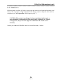
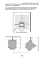
A copy of the safety label for a Quest pellet stove is shown in Figure 1 below. The safety label
is located on the underside of the hopper lid on all Quest stoves. This label contains important
information about the installation and operation of your stove. In addition, your stove's serial
number is located on this label (preceded by "WH-Q"). This manual is provided as a supplement to the information on the safety label. Please read the safety label carefully.
(Figure 1) Quest Safety Label
1
Safety Information (cont.)
SAFETY PRECAUTIONS
Fuel - With advanced UltraGrate technology, the Whitfield Quest is designed and approved for
the burning of wood residue pellets with up to 3% ash content. The burning of agricultural
residues (such as corn and alfalfa), waste paper, or cardboard in pellet form is not permitted.
Failure to comply with this restriction will void all warranties and the safety listing of the stove.
Confer with your dealer for more information on approved pellet fuels.
Continuous Operation - When operated correctly, the Whitfield Quest cannot be over-fired.
Continuous operation at a maximum burn can, however, shorten the life of the electrical components (fans, auger motor, and electronic controls) and is not recommended.
Liquid Flammables - Gasoline or other flammable liquids must never be used to start or
"freshen up" the fire. Keep all such liquids well away from the stove at all times.
Ashes - Any ashes removed from the Whitfield Quest must be deposited in a metal container
with a tight-fitting lid. The closed container of ashes should be placed on a non-combustible
surface or on the ground, well away from all combustible materials, pending final disposal. If
the ashes are disposed of by burial in soil or otherwise locally dispersed, they should be
retained in the closed container until all cinders have thoroughly cooled.
Power - The appliance is provided with a grounded electrical cord. This cord should be connected to a standard, 115 volt, 60 Hz grounded electrical outlet. The approximate continuous
power requirement is 200 Watts. The power supply cord must be routed to avoid contact with
any of the hot or sharp exterior surface areas of the stove. The stove will not operate without a
power source for the fans and fuel feed system.
Auger - Pellet fuel is fed to the burn grate by an auger. This auger is driven by a high torque
motor. The auger is capable of doing serious harm to fingers. Keep pellets in the hopper at all
times and keep fingers away from the auger. The auger can start and stop automatically at any
time while the stove is running.
Soot Formation - Burning with insufficient combustion air will result in the formation of soot.
This soot may be deposited on the windows, in the flue, and in the heat exchangers. If the
appliance has been vented through the wall and terminated, this soot may stain the outside of
the house. This is a hazardous situation, in addition to being an inefficient use of pellet fuel.
Check your stove frequently, and adjust combustion air as required.
Cleaning - There will be some build-up of dust and smaller quantities of soot or creosote in the
exhaust system over the burn season. This will vary due to the ash content of the fuel being
burned. Conduct frequent inspections, initially, to determine appropriate cleaning intervals.
2
Safety Information (cont.)
SAFETY PRECAUTIONS-continued
Smoke Detector - Depending on your local codes, a smoke detector may be required in the
room where the stove is installed. We recommend that smoke detectors be installed in all
homes and maintained in an operational condition at all times, no matter whether you are using
a heating appliance or not.
Exhaust Pipe - The appliance is provided with an exhaust connector for a listed 3-inch,
type "L", double-wall pellet vent pipe with a stainless steel inner liner. Single wall, stainless
steel pipe (rigid or flexible) is acceptable for insert installations.
Mobile Home Installation - Any Whitfield Quest stove installed in a mobile home must be
connected to a source of outside air, electrically grounded to the steel chassis, and bolted to the
floor (unless otherwise specified by state or local authorities) to meet H.U.D. requirements.
SAFETY TESTING
Whitfield Pellet Stoves and Fireplace Inserts are safety tested and listed by Warnock Hersey
Professional Services, Ltd., an accredited testing laboratory. Tests were conducted in accordance
with the specifications and procedures listed in ASTM E-1509 for Pellet Heaters and UL 1482
for solid fuel room heaters, as well as CSA and ULC standards. UL 1482 states requirements for
installation as a Freestanding room heater, or hearth insert for masonry or metal (zero clearance)
fireplaces. This appliance is designed specifically for use with approved pelletized fuels. It is
tested and listed for residential installation, according to current national and local building
codes, as either:
• Freestanding Room Heater
• A Hearth Insert (when installed into a masonry or factory built fireplace)
• A Mobile Home Heater
PLEASE NOTE:
This stove is not intended for use in commercial installations, other than
the dealership where the stove is being sold, without prior written
approval from Pyro Industries, Inc.
3
Safety Information (cont.)
AUTOMATIC SAFETY FEATURES
Power Outage - During a power outage, the stove will shut down safely. It will not automatically
restart when the power is restored. However, a momentary power interruption may not shut your
stove down. A small amount of smoke will likely leak from the top of the window glass, the
hopper and from the combustion air intake, if the stove is vented horizontally. This will not
persist for more than 3 to 5 minutes and will not be a safety hazard. Your smoke alarm could be
activated.
To re-light the stove, follow the normal procedure for starting your stove.
IMPORTANT: If the area in which you live is prone to frequent power outages,
it is recommended that a minimum of 8 feet (2.5 m) of vertical vent pipe be
included in a freestanding installation. In the event of a power failure, this will
create a natural draft and minimize any spillage of exhaust gases into the room.
Overheating - A high temperature switch will automatically shut down the stove if it overheats.
The stove will need to be manually re-lit. Allow up to 45 minutes cooling time before re-lighting.
If the overheating continues, contact your dealer for more information.
Safe Shut Down - While the stove is operating press the auger ''on'' button on the control
board to turn the fuel feed off. Pellets will stop feeding and the red auger "on" light will stop
blinking. Both fans will continue to operate. The fans will automatically turn off after 15 to 40
minutes. The low temperature switch will also shut the stove down safely if it runs out of fuel.
4
Pellet Fuel Information
GENERAL INFORMATION
The Whitfield Quest, with its UltraGrate burn system, has been designed to burn wood residue
pellets with up to 3% ash content. Only Pellet Fuel Institute (P.F.I.) approved fuels should be
used in this stove. Wood Pellets manufactured to the P.F.I. Certification Standards are available
in two grades: STANDARD and PREMIUM. The premium grade pellets have a lower ash content than the standard grade. The P.F.I. specification for standard and premium grade residential
pellet fuel follows:
CHLORIDES (Salt):
BULK DENSITY:
MOISTURE CONTENT:
ASH CONTENT:
FINES:
Less than 300 p.p.m.
40 lb./ cu. ft. minimum
8% maximum
3% maximum(Standard Grade)
1% maximum (Premium Grade)
0.5% maximum through a 1/8” screen
CLINKERING
Silica (or sand) in the fuel, along with other impurities, can cause clinkering. A clinker is a hard
mass of silica formed in the burning process. Clinkering is a function of the fuel (not the stove),
and adversely affects the performance of the stove by blocking off the air passages in the grate.
Even a P.F.I. approved pellet fuel may tend to clinker. A clinker can be removed from the burn
grate and placed in the ash pan with the use of the grate scraper/ash pan tool furnished with
your stove. See Routine Cleaning & Maintenance for more information.
ASH
The frequency of ash removal and other maintenance performed on the stove is directly proportional to the ash content of the fuel and how frequently you use your Whitfield stove. Low ash
fuel may allow longer intervals between cleaning, however, a stove burning high ash fuel may
need to be cleaned everyday.
PLEASE NOTE: Pyro Industries, Inc., has no control over the manufacturing of pellet fuel and
will not be held responsible for poor stove performance or any damage caused by inferior pellet
fuels.
5
Pellet Fuel Information (cont.)
FUEL FEED RATES
Different brands of pellets will feed at varying rates due to their size (length and diameter), and
density. This may require a slight adjustment in the damper control or the pellet feed control to
compensate (see Stove Operation which begins on page 7).
CAUTION: This product is not designed to burn agricultural pellets (such as
corn and alfalfa) or pelletized fuels from waste paper, cardboard, etc. The use
of unapproved, dirty, wet and/or high salt content fuel will void the stove's
warranty!
Contact your authorized Whitfield dealer for more information, if needed.
6
Stove Operation
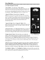
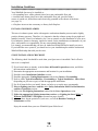
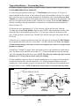
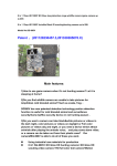
CONTROL BOARD FEATURES
"Start" Button - The push-button "Start" button
activates the convection fan and the combustion (exhaust) fan. If the
exhaust does not reach proper operating temperature within 30 minutes, the stove will automatically shut down. The fans can be restarted
by pushing the "Start" button again after the 30 minute cycle.
"Auger On" Button - The push-button "Auger On"
button activates the fuel feed (auger) motor only. The start button
must be activated first to send power to the auger "on" button. If the
auger "on" button is pushed again, the fuel feed will stop and the fans
will continue to operate until the stove has cooled down sufficiently
(this may take up to 45 minutes); then both of the fans will
automatically turn off.
"Auger On" Light - The red "Auger On" light (L.E.D.)
on the control panel indicates when there is power to the auger motor.
When the auger motor is activated, this light will blink as the auger
motor cycles on and off.
"Pellet Feed" Knob - The "Pellet Feed" knob allows you adjust the
heat output of your stove by controlling the rate at which pellets are
fed to the burn grate. Turning this knob counter clockwise lowers the
fuel feed rate; turning the knob clockwise increases the fuel feed rate.
(Figure 2)
"Damper Control" Knob - This knob allows you to adjust the
Stove
Control Board
damper, which controls the amount of combustion air that reaches the
burn grate. For an efficient flame, the damper control knob should be
adjusted whenever the "Pellet Feed" knob setting (fuel feed rate) is changed. This knob is
located on the upper third of the control board (see Figure2). When the damper has been correctly adjusted, you will observe a brisk, yellow-to-whitish flame (refer to video for proper
flame appearance).
NOTE: The proper air settings will vary from stove to stove due to installation altitude, and
the fuel being burned. The LOW, MEDIUM, and HIGH marks should be used only as a
guide for matching pellet feed settings to damper settings. Choose a setting that does not
allow fuel to "pile up" in the grate. Adjust damper to get an active, bright yellow-white flame.
"Fan High/Low" Button - The "Fan High/Low" button sets the speed of the convection fan
motor to either a high or low setting. Choose the high setting to extract the most heat from your
stove; choose the low setting when feeding pellets at lower rates.
7
Stove Operation (cont.)
PRELIGHTING INSTRUCTIONS
When lighting your Whitfield stove for the first time, the auger feed tube must be "primed"
(filled with pellets). Also, if the stove ever runs completely out of fuel, the auger system will
need to be primed again. To prime the auger feed tube:
1. Fill the hopper with an approved pellet fuel and plug the stove into the wall outlet.
2. Press the "START" button on the control panel to activate both fans. Push the "Auger On"
button on the control panel (this starts the auger motor). Next, turn the "Pellet Feed" knob to
"HIGH" (the maximum feed rate).
3. Look through the stove’s window. The auger is fully primed when you can see the first
pellets dropping into the grate. This will take 10 to 15 minutes.
4. Once the auger is primed, unplug the powercord and wait for a minimum of 30 seconds to
turn off the fans and auger. [Note: This step is followed only when priming the auger and will
not need to be performed every time you start the stove, if fuel is in the hopper.] Once the stove
has shut down, plug the powercord back into the wall outlet.
LIGHTING STOVE WITH THE OPTIONAL FASTFIRE™ SELF-IGNITER
If you have purchased the optional FASTFIRE™ Self-Igniter from your dealer, you will need to
perform the following start-up procedure:
1. Make sure the auger is primed (see Pre-Lighting Instructions above), then simply push the
"START" button on the control board to activate the igniter.
2. Set the "Damper Control" knob in the "MEDIUM" range to obtain: proper air flow for
combustion.
3. Set the "Pellet Feed" control knob to the desired position.
4. Push the "Auger On" button to supply power to the auger motor. Pellets will start feeding
into
the grate and should begin to ignite within three to seven minutes. The self-igniter will automatically shut off after 15 minutes.
5. It may be necessary to adjust the damper control knob after pellets have ignited and the stove
has had a few minutes to warm up.
8
Stove Operation (cont.)
LIGHTING STOVE WITHOUT THE OPTIONAL FASTFIRE™ SELF-IGNITER
1. If lighting your stove for first time, first follow Pre-lighting Instructions on page 8. Place a
recommended fire starter (see your dealer for an appropriate fire starter) in the burn grate and
put a handful of pellets on top of the starter (if using a gel starter, put the pellets in the grate
first).
WARNING: DO NOT USE FLAMMABLE LIQUIDS TO START YOUR STOVE.
WARNING: DO NOT OPERATE STOVE WITHOUT BURN GRATE IN PLACE
2. Light the fire starter in the burn grate with a match, and close the door. Turn the pellet feed
knob to the "MEDIUM" setting.
3. Turn the "Damper Control" knob to the "MEDIUM" setting .
4. After approximately 10 seconds, press the "Start" button. You will notice that the fire will
become active, and air will flow out of the heat exchanger tubes.
5. Once the pellets in the grate are burning sufficiently (red hot coals), press the "Auger On"
button to activate the auger motor. If the auger is "primed" (see Pre-Lighting Instructions on
page 8), pellets will now begin to feed into the burn grate.
6. After the fire is burning well, adjust the "Pellet Feed" knob to the desired setting. The red
"Auger On" light will blink on and off. Adjust the damper control knob into the same range as
the pellet feed knob, or as necessary for proper combustion. Look for an active, bright
yellow-white flame.
7. Push the "Fan High/Low" button to set the convection fan to the “HIGH” (or “LOW”) setting. Each time the button is pushed, the convection fan speed switches to the alternate setting.
The stove can be safely operated at either the “HIGH” or “LOW” convection air setting for any
fuel feed rate.
TURNING OFF THE STOVE
To turn off the stove, simply push the "Auger On" button once, which will turn off the auger
motor, and stop the fuel feed. Both fans will run until the stove has cooled down sufficiently.
At this point, a low-limit snap switch will activate to automatically shut off the stove.
9
Stove Operation (cont.)
GENERAL OPERATING INFORMATION
Proper Burn Characteristics - The flame in your stove should be bright yellow during normal
operation. If the flame becomes lazy with a reddish/orange color, the damper control knob will
need to be turned clockwise (set higher) to provide more combustion air.
Excessive amounts of fly-ash built up in the grate, clinkers in the grate, or leakage of air (if the
grate is not properly seated) will starve the fire for air and pellets will pile up in the grate.
Follow the grate cleaning procedure outlined in the Routine Cleaning & Maintenance section.
If the grate blockage problem persists review the trouble-shooting section at the end of this
manual.
NOTE: If the flame is smoky red/orange with evidence of soot at the top of the flame, your
stove needs more combustion air; adjust the damper until the flame begins to ‘dance’. If the
flame is 'short' at the higher burn rates or if the pellets are burning up in the grate before
new pellets are fed into the fire, adjust the damper for slightly less combustion air. The
damper position will probably need to be changed whenever the pellet feed setting is changed.
The damper setting should be increased slightly when switching from a premium grade pellet
to a standard grade or other higher ash pellet.
Pellet Feed/ Pellet Size - The pellet feed system is designed to handle a wide range of pellet
sizes up to a maximum of 5/16" diameter. You may notice a difference in the burn if you
change pellet fuel sizes. Different pellets may feed at considerably different rates. The longer
the pellet, the slower it will feed and vice versa.
If the stove will not stay burning at the minimum fuel feed setting, that pellet type may not be
feeding fast enough. If this happens, reduce the amount of combustion air using the "Damper
Control" knob, or increase the fuel feed rate by using the "Fuel Feed" knob .
Long Burn Time - The stove may be safely operated on a continuous basis. A 40 pound bag of
pellets should last approximately 12 hours on the "HIGH" fuel feed setting and up to 40 hours
on "LOW," depending on the pellet fuel burned.
Ash Release Slide Plates - See boxed statement below:
IMPORTANT: When operating the freestanding stove, it is important to make
sure that the ash release slide plates are completely closed. Air leakage
around even partially open plates will negatively affect the stove's performance
and may cause pellets to pile up in the grate.
10
Routine Cleaning & Maintenance
ROUTINE CLEANING & MAINTENANCE
The following areas need to be routinely inspected for ash build-up, and cleaned
when necessary:
1 Burn Grate (“UltraGrate™”)
2 Heat Exchanger Tubes
3 Heat Exchanger Baffle
4 Ash Pan(s)
5 Exhaust Vent
6 Rope Gasket (around door, ash pan, and window areas)
7 Fan Motors - Combustion and Convection
The amount of ash build-up in your stove is directly proportional to the ash content of the fuel
you are burning (see Pellet Fuel Information, page 5). After a period of time (a week, or so)
inspect the burn grate and heat exchanger tubes, heat exchanger baffle, ash pan and exhaust
vent areas. Set an appropriate maintenance schedule for each area based on the amount of ash
you find. Your stove’s performance will be affected if enough ash accumulates to restrict air
flow in any area. These items should also be checked periodically, and may require cleaning
and/or maintenance:
The seven topics listed above are discussed in more detail on the following pages. In addition,
windows and plated accessories may be cleaned, once cool, using a soft cloth and an appropriate commercial all-purpose cleaner suitable for glass. Do not use products that may leave a
flammable residue.
NOTE: The stove will need to be shut off and cooled down before routine
cleaning is performed. ALWAYS DISCONNECT POWER before doing any
routine cleaning or repair work on the stove.
11
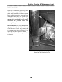
Routine Cleaning & Maintenance (cont.)
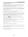
BURN GRATE
The burn grate should be inspected periodically to ensure that the airflow has not become
blocked with ash or clinkers. The burn grate
can easily be cleaned with the grate
scraper/ash pan tool (see Figure 3), or it can be
removed for more extensive cleaning. When
burning "Standard" grade pellets, it will be
necessary to clean the ash pan more often than
when burning "premium" grade pellets. On
the insert model, it is very important to monitor the ash build-up under the burn grate, to
prevent restriction of combustion air flow
through the burn grate. Check the center ash
pan regularly. Empty before the ash builds up
to the bottom of the grate.
(Figure 3) - Cleaning Burn Grate
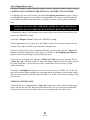
HEAT EXCHANGER TUBES
A rod located above the convection air louvers is used for cleaning the heat exchanger tubes. Be
sure the door is closed while you are scraping these tubes. By pulling this rod up and down a
few times, you will clean the fly ash off the heat exchanger tubes (see Figure 4). A hole is
provided in the handle of your grate scraper tool for pulling this rod.
NOTE: If your stove was recently turned off, the rod will still be hot.
Tube
Scraper
Rod
Heat
Exchanger
Baffle
(Figure 4) Cleaning Heat Exchanger Tubes
(Figure 5) Heat Exchanger Baffle Installed
12
Routine Cleaning & Maintenance (cont.)
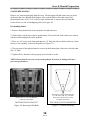
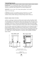
ASH PAN(S)
Freestanding Model - The ash pan will have to be emptied periodically. The ash pan on the
free-standing model is located in the pedestal tower. It can be removed by turning the T-Bar
latch fully counter-clockwise. Then pull ash pan away from stove. Ash that accumulates around
the grate can be “dropped” into the ash pan without opening the firebox door. Simply pull open
the ash release slide plates (show in Figures 6 and 7) using the grate scraper tool provided.
Remove the ash pan as shown in (Figure 8). NOTE: Make sure to fully close the plates when
finished. Failure to close the ash release slide plates completely may cause the fuel to burn
poorly (due to reduced air flow through the grate, which may then cause pellets to "pile up"
in the grate.
Ash Slides Fully Open
Ash drops through
these openings
Ash Slides
In Fully
Closed Position
(Figure 6) - Locating Ash
Release Slide Plates
(Figure 7) - Opening Ash
Release Slide Plates
(Figure 8) - Emptying Ash
Pan on Freestanding Stove
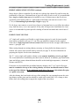
Insert Model - There are two separate ash pans to empty on the insert model: (1) a small pan
directly beneath the burn grate, and (2) a larger pan that covers the left and right sides of the
firebox. Open the firebox door to access the ash pans. Scrape the accumulated ash into the ash
pans using the grate scraper tool, pay special attention to the grate itself. Next, remove the
center, smaller pan using the grate scraper tool (see Figure 9). Be sure to dump the ashes into a
non-combustible container. Return the small ash pan to the stove. Repeat this procedure for the
larger ash pan (see Figure 10). Close the firebox door and latch it.
Note: Dispose of the ash in accordance with the instructions found on page 2 of this manual!
(Figure 9) - Emptying Small Ash Pan
on Insert Stove
(Figure 10) - Emptying upper Ash Pan
on Insert Stove
13
Routine Cleaning & Maintenance (cont.)
EXHAUST DUCTS
Inspect the exhaust ducts periodically and
clean when necessary. Fly ash will accumulate at all bends in the exhaust system.
Based on this inspection, determine how
often, and to what extent, the exhaust system will need to be cleaned. Note: Large
amounts of fly ash build-up will restrict
combustion air flow and reduce the
stove's efficiency.
On insert models, To access the clean out
cup, open the right-hand shroud panel
(when the stove is cold), and remove the
tee clean-out cup (shown in Figure 11) to
inspect the ash build-up in the exhaust
system. Twist the clean-out cup to the left
to release it.
(Figure 11)
Clean-Out Cup Connected to Tee
14
Routine Cleaning & Maintenance (cont.)
ROPE GASKET
The rope gasket should be checked periodically and replaced or repaired if necessary. This gasket is located around the firebox door and windows (plus the ash pan on freestanding models).
A one-inch strip of paper may be used to test the integrity of the door seal. Close the door on
the paper in several different locations and pull. A slight amount of friction is normal. The door
gasket does not need to be "tight" in all areas, since a small amount of air drawn into the stove
around the gasket is not hazardous or detrimental to the stove's performance.
FAN MOTORS: COMBUSTION AND CONVECTION
The two fan motors require lubrication annually with not more than two drops of a high quality, non-detergent oil (your dealer can make a recommendation) at the lubrication points shown
below. Do not over-oil the motors! Too much oil can shorten motor life.
The combustion fan, (exhaust Fan) located on the right side of the stove, has two black rubber
plugs that must be removed. To access the exhaust fan, the right side panel may be opened by
removing the top screw (between the louvers) and popping open the "bulb" latch at the bottom.
To gain access to the convection fan, open the left side panel (follow the above procedure for
opening the right side panel ). On the convection fan, the oiling ports are the “half-moon” openings in the motor housing.
Note: The orientation of the motors may vary from fan to fan. The oiling ports, therefore,
may not be in exactly the same location as shown in these photos.
Oil Port
Oil Port
(Plugs in Place)
Oil Port
(Failure 14) - Combustion Fan Oiling Ports
(Figure 13) - Convection Fan Oiling Ports
15
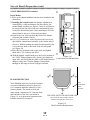
Stove & Hearth Preparation
STOVE PREPARATION
Remove any external packaging from the stove. Lift the hopper lid and remove any pre-packaged items that were shipped in the hopper. Also open the firebox door and remove any
pre-packaged items. Use a 7/16" socket or open end wrench, to remove the two bolts that
secure the stove to the wood shipping pallet (see Figure 16)
Freestanding Model:
1. Remove the pedestal from its box and place it beside the stove.
2. With a helper, lift the stove onto its pedestal base. The stud on the front of the stove must fit
into the front mounting hole on the pedestal.
3. Place one 1/4" nut over the front stud and two 1/4" bolts into the two holes at the rear, where
the stove was originally secured to the pallet (see Figure 17).
4. The rear panel of the pedestal must be secured to the bottom plate of the stove with the other
two 1/4" bolts.
5. Tighten all five fasteners with a properly sized wrench or socket.
NOTE: Ensure that the stove sits evenly on the pedestal. Excessive air leakage will cause
poor stove performance.
Remove the two 1/4" bolts from the
underside of the pallet
Attach stove to the pedestal using one
1/4" nut in the front, two 1/4" bolts
in the back corners and two in the
rear panel (not shown)
BOTTOM VIEW OF PALLET
TOP VIEW OF STOVE PEDESTAL
(Figure 16) Removing Pallet Bolts
(Figure 17) Pedestal Mounting
16
Stove & Hearth Preparation (cont.)
STOVE PREPARATION continued
Insert Model:
1. Refer to the shroud installation instructions included in the
shroud box.
2. Installing the control board- the damper adjustment is
controlled by a cable mechanism. On insert stoves, the
control board assembly (see Figures 2 and 18) will need to
be removed from the side of the stove and attached to the
back of the shroud side panel. After attaching the left side
shroud panel to the stove, follow this procedure:
a) Remove the four lock-nuts from the back of the shroud
left panel and set them close by.
b) Use a 1/4" nut driver or socket to remove the two screws
that hold the control board assembly to the bottom side of
the stove. Without turning the control board assembly, slip
it over the four studs on the back of the left side panel
(see Figure 18).
c) Place the four lock-nuts back on the studs, and tighten
them with a 3/8" socket or nut driver.
d) With the damper control knob set to the lowest position of
the “LOW” Range (damper fully closed), look under the
auger tube, and verify that the cable is still hooked into the
damper control arm. Turn the Damper Control knob
through its full range to check for proper function.
(Figure 18)
Control board on Shroud Panel
6”
6”
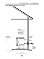
FLOOR PROTECTION
Noncombustible
Floor
protector
Your Whitfield pellet stove must be installed
on a non-combustible protective floor pad
(3/8" minimum thickness material), or on a
masonry hearth. The hearth or floor pad
must extend a minimum of 6" from the front
and both sides of the stove (as shown in
Figure 19), or to the nearest permitted cormbustible material if less than 6".
6”
TOP VIEW OF STOVE ON FLOOR PAD
Floor protector must extend at least 6"
from the front and sides of the stove.
(Figure 19)
Floor Protection Requirements
17
Stove & Hearth Preparation (cont.)
CLEARANCES TO COMBUSTIBLES
Figure 20 shows the minimum clearances to combustible materials that must be maintained.
Keep all combustibles at least 18" away (measured horizontally) from the glass windows.
Maximum alcove depth allowed is 24", minimum alcove height allowed is 47-1/2".
Min. 18”
Min. 4”
Min. 4”
Max. 24”
Min. 1”
Min. 1”
Min. 4”
Min. 1”
(Figure 20) - Clearances to Combustible Materials
18
Installation Guidelines
Your Whitfield Quest may be installed as:
• A freestanding stove with a pedestal placed on a non-combustible floor pad.
• A mobile home heater placed on a non-combustible floor pad, provided with a
source of outside air, bolted down and electrically grounded to the chassis of the home
(see page 31) .
• A fireplace insert set into a masonry or factory built fireplace.
INSTALLATION DISCLAIMER
This stove's exhaust system works with negative combustion chamber pressure and a slightly
positive chimney pressure. Therefore, it is imperative that the exhaust system be gas-tight and
installed correctly. Since Pyro Industries, Inc., has no control over the installation of your stove,
Pyro Industries grants no warranty, implied or stated, for the installation or maintenance of your
stove, and assumes no responsibility for any consequential damage(s).
It is strongly recommended that you have an Authorized Whitfield Dealer install your stove.
If you install the stove yourself, you should review your installation plan with the Authorized
Whitfield Dealership that sold you the stove.
STOVE INSTALLATION CHECKLIST
The following check list should be used when your Quest stove is installed. Check off each
item as it is completed.
❑ If you haven't done so already, read the Stove & Hearth Preparation section, and follow
the instructions outlined there.
❑ Determine the appropriate measurements and location for your installation.
❑ Read this entire Installation Guidelines section.
❑ Read the appropriate Venting Requirements sub-section: Insert or Freestanding.
❑ Refer to either Typical Installations - Freestanding or Typical Installation - Insert Stove
(depending on your stove type) to find the appropriate installation.
❑ Pre-fit all items before you install, fasten, cut holes or set up the stove permanently.
❑ Prior to lighting your stove read the entire Safety Information Pellet Fuel Information,
andStove Operation sections.
❑ Follow the Pre-Lighting Instructions outlined in the Stove Operation section.
❑ Follow the appropriate lighting instructions section: see Lighting the Stove With (or
Without) FASTFIRE™ Self-Igniter (located on pages 8 and 9).
❑ After you have begun operation of your stove, review the Routine Cleaning &
Maintenance section.
Enjoy the warmth from your new Whitfield Quest Pellet Stove!
19
Installation Guidelines (cont.)
DETERMINING EQUIVALENT PIPE LENGTH
To determine whether a 3” or 4” exhaust system is required for your installation, review the
sample installation below. Fill out the top chart, and calculate your total equivalent pipe length.
After you have the total equivalent pipe length, use the chart at the bottom of the page to determine if your installation requires 3” or 4” exhaust pipe.
Type of Pipe # of Elbows or Feet of pipe
Equivalent Feet Total Equivalent Feet
o
Elbows
x
5(1.5m)
o
Elbows
x
3(1m)
Horizontal
Pipe
x
1(.3m)
Vertical
Pipe
x
5(.15m)
90
45
A- 90 Deg. Elbow
E- 8’ Vertical Pipe
B- 1’ Horizontal Pipe
F- 2’ Horizontal Pipe
C- 45 Degree Elbow
G- 90 Degree Tee
D- Standoff Braces
H- Wall Thimble
Pipe Selection Chart
30
4 INCH DIAMETER ONLY
20
B
A
C
D
NOTE: For the example installations
above, 4 inch diameter pipe would be used
for installations at altitudes above 3,000
feet; 3 or 4 inch pipe would be suitable
below 3,000 feet.
E
10
F
3 OR 4 INCH DIAMETER
0
1
2
3
4
5
6
7
8
9
G
10
Altitude in Thousands of Feet
(Figure 22)-Equivalent Length versus Altitude Chart
Sample Installation Chart
Type of Pipe
H
(Figure 21)-Sample Pipe Configuration
# of Elbows or
Feet of pipe
Equivalent Feet Total Equivalent Feet
o
2
x
5 ft. (1.5m)
10 (3m)
45 Elbows(C)
o
1
x
3 ft. (1m)
3 (1m)
Horizontal Pipe(B&E)
3
x
1 ft. (.3m)
3 (1m)
Vertical Pipe(D)
8
x
.5 ft. (.15m)
4 (1.2m)
90 Elbows/Tee(A &F)
20
TOTAL: 20
Venting Requirements
IMPORTANT: It is recommended that only an authorized dealer install your
pellet stove. The following installation guidelines must be followed to ensure
conformity with both the safety listing of the stove and local building codes.
WARNING: Do not vent into a flue serving another appliance. Do not install a
damper in the exhaust pipe.
CAUTION: On all direct vent installations (short, horizontal runs), care should
be taken when choosing a location for terminating the vent. It is not recommended to directly vent the exhaust pipe on the prevailing wind side of the house.
FREESTANDING STOVE VENTING
A listed 3 or 4 inch type "L" pellet vent exhaust system must be used for freestanding installations and attached (and sealed) to the pipe connector provided on the back of the stove. Use a
3-to-4 inch adapter or a 3-to-4 inch "tee" in order to run 4 inch pipe. The vent termination must
be located no less than 48" (1.2m) from any opening through which flue gases could re-enter
the building (such as windows and doors), not less than 24" (0.6m) from an adjacent building,
and not less than 7' (2.2m) above grade when located near public walk-ways. The final termination of the exhaust system must be configured so that flue gases do not jeopardize the safety of
people passing by, overheat combustible portions of nearby structures, or enter the building.
Keep brush, plants and shrubs at least 36" (0.9m) away from the vent termination. Since sparks
may escape from the exhaust pipe of any stove, always use caution when positioning the vent
pipe. NOTE: Refer to the pipe manufacturer's instructions when installing and terminating the exhaust.
21 3/8”
21”
5 7/8”
291/2”
3 1/2”
11 1/2”
10”
9”
RIGHT SIDE VIEW
REAR VIEW
Dimensional Tolerance +/-1/4”
Pipe Locations measured to Centerline
(Figure 23)
Freestanding Stove Dimensions
21
Venting Requirements (cont.)
FREESTANDING STOVE VENTING continued
Ninety-degree elbows accumulate fly ash and soot, reducing the exhaust flow and lowering the
performance of the stove. Horizontal runs of pipe will collect fly ash as well. It is recommended
that a single or double clean-out tee be installed at every 90 degree turn so that fly ash can
accumulate at the bottom of the tee. Total length of horizontal vent must not exceed 25 feet
(7.7m; see Determining Equivalent Pipe Length on page 20).
If a 90 degree turn connects a vertical run of pipe to a horizontal run (as you follow the exhaust
away from the stove), a tee is not required. At any other 90 degree turn, installation of a cleanout tee is recommended to permit periodic cleaning of both the horizontal and vertical runs of
pipe.
INSERT STOVE VENTING
A 3" single-wall, stainless steel flexible or rigid exhaust pipe may be used for insert installations in place of double-wall, type "L" vent. The pipe should be connected to the supplied
clean-out tee. High-temperature silicone sealant should be used at the vent pipe connections to
ensure a “gas-tight” seal.
When venting through an existing chimney (masonry or factory built) the chimney must be
cleaned. All creosote, dust and ash must be removed (see page 32 for more information on
preparing the fireplace for the insert installation).
The "L" vent or single wall stainless exhaust system must be installed so as to be gas-tight!
The vent manufacturer's installation procedures must be followed. In addition, pipe connections,
joints and all pipe seams within the home should be sealed with high-temperature, vulcanized
silicone sealer (RTV).
If an insert is to be installed into an unlined masonry chimney, the 3" or 4" rigid or flex pipe
must be extended to the top of the existing chimney. All insert installations must be lined
to the top of the chimney (10 feet minimum length above the stove) with stainless flex pipe
or a pellet vent system.
After the chimney has been lined to the top of the existing flue, any opening between the existing chimney and the pipe/vent liner should be sealed with a metal plate. Use a clamp or other
fixture above the sealing plate to support the weight of the vent system.
22
Venting Requirements (cont.)
INSERT STOVE VENTING - continued
21”
Cast exhaust duct
“Tee” branch
Clean-out “tee”
Removabl
e
Clean-out
Cup
10”
21”
(Figure 24)-Insert Pipe Adapter Connection
W
H
DISCRIPTION
H
STD SHROUD ASSY 40 1/2”
28”
LRG SHROUD ASSY
31”
(Figure 25)-Front View of Insert
Contact your dealer for further assistance or information on installing
your Whitfield Quest Insert.
23
W
44”
Venting Requirements (cont.)
INSERT STOVE VENTING - continued
15 1/2”
20”
(Figure 26)
Left Side View of Insert
30 1/2”
24 1/4”
24 1/4”
(Figure 27)
Back View of Insert
24
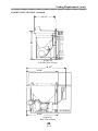
Typical Installations – Freestanding Stove
STANDARD HORIZONTAL EXHAUST
1. Locate the proper position for the type "L" Wall Thimble (refer to Figure 28 for types of
pipes mentioned in this section). Avoid cutting wall studs when installing your pipe. Use a saber
saw or key hole saw to cut the proper diameter hole through the wall to accommodate the Wall
Thimble. Use extreme caution to avoid cutting into power lines within the wall of the home. The
hole size will depend on the brand of pellet vent that you are using. Install the Wall Thimble in
the hole according to the pipe manufacturer's instructions. A standard horizontal installation is
shown in (Figure 29).
2. Position the stove approximately 12" (0.3m) from the wall on the floor pad. Push type
"L-vent" pipe through Wall Thimble. Squeeze a bead of RTV high-temperature silicone sealer
around the end of the machined portion of the 3" (76 mm) pipe connector on the back of the
stove. Firmly push on a section of type "L-vent" pipe until the inner pipe liner pushes into the
RTV bead.
3. Push the stove (with pipe attached) towards wall. The pipe will go through the Wall Thimble.
Do not position the back of the stove closer than 1" (25 mm) from the wall. Note: 6 to 8 inches
of back clearance will provide easier access for servicing the stove, however, a larger hearth
pad may be required.
4. Install type "L-vent" 45 degree elbow with rodent screen or cap (optional) on outside end of
pipe. The rodent screen should be no less than 1/2" (13 mm) mesh and may clog with soot and
ash if left unattended during the burn season. NOTE: The end of the exhaust pipe must extend a
minimum of 12'' (0.3m) from the outside wall of the building.
5. If the installation requires a source of outside combustion air; cut a separate hole through the
wall for the fresh air tube. This tube should be 1-5/8” (42mm) minimum diameter non-combustible pipe. Connect outside air pipe to air inlet on stove. This tube must be terminated with a
90 degree elbow or hood. NOTE: Air may also be drawn from a crawl space under the home.
BACK SIDE OF STOVE
Quick
Disconnect
Straight “L-vent”
Pipe
Wall
Thimble
Wall
Thimble
Exhaust
Port
Inlet-Air
Port
Lytherm
Gasket
Holes through
the Wall for the
Thimble &
Fresh Air Pipe
Metal Fresh
Air Pipe
(Figure 28) - Horizontal Installation Components
25
45o Degree
Elbow Joint
for Fresh
Air Pipe
Typical Installations – Freestanding Stove
STANDARD HORIZONTAL EXHAUST - continued
IMPORTANT:
We recommend at least
2” to 3” min. between
the stove and wall,
to allow room for
servicing, power cord
and the hopper lid.
6” Minimum
from front of
stove to edge of
non-combustible floor
protection
1” Min.
6” Minimum
1” Minimum
clearance
from back
of stove to
combustible
material
12” Min.
Noncombustible floor protection
(Figure 29)
Standard Horizontal Installation
26
Pipe must
extend a
minimum of
12 inches
from outside
wall.
Typical Installations – Freestanding Stove (cont.)
VENTED INTO MASONRY CHIMNEY
A freestanding Quest may be vented into an existing flue. If a liner is run all the way to the top
of the existing chimney, the top should be sealed with a metal plate (aluminum, or galvanized
or
stainless steel). Start the vertical run with a "tee" at the back of the stove. Other options are
Optional
Complete
Liner
IMPORTANT:
We recommend at least
2” to 3” min. between
the stove and wall,
to allow room for
servicing, power cord
and the hopper lid.
1” Minimum
clearance from
back of stove to
combustible material
6” Minimum
from front of
stove to edge of
non-combustible floor
protection
Option:
Clean-out door
to access “tee”
6” Min.
All vertical pipe
runs should
begin with a
3” or 4”
clean-out “tee”
(Figure 30)
Freestanding Vented Into Masonry Chimney
27
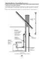
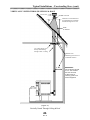
Typical Installations – Freestanding Stove (cont.)
VERTICALLY VENTED THROUGH CEILING & ROOF
VENT CAP
STORM COLLAR
Follow the vent manufacturer's
recommendation for minimum
termination height above roof
ROOF
FLASHING
Use ceiling support or
firestop when venting
through a floor or ceiling
Maintain 3 inch
minimum pipe clearance to
combustible surfaces.
3” Min.
6” Min.
(Figure 31)
Vertically Vented Through Ceiling & Roof
28
IMPORTANT:
We recommend at least
2” to 3” min. between
the stove and wall,
to allow room for
servicing, power cord
and the hopper lid.
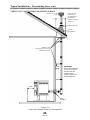
Typical Installations – Freestanding Stove cont.)
VERTICALLY VENTED THROUGH CEILING & ROOF
Follow the vent
manufacturer's
recommendation
for minimum
termination height
above roof
VENT CAP
STORM COLLAR
ROOF
FLASHING
Maintain 3 inch
minimum pipe clearance to
combustible surfaces.
3” Min.
IMPORTANT:
We recommend at least
2” to 3” min. between
the stove and wall,
to allow room for
servicing, power cord
and the hopper lid.
6” Min.
WALL
THIMBLE
(Figure 32)
Vented Out Through Wall & Up Through Roof
29
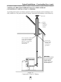
Typical Installations – Freestanding Stove (cont.)
VENTED OUT THROUGH EXTERIOR WALL & UP THROUGH ROOF
CONNECTED TO A METAL (CLASS 'A') CHIMNEY
An existing metal (Class 'A') chimney (used for wood stoves) may be used to terminate a vertically vented stove. The pellet vent may be directly connected to the chimney or run all the way
RAIN CAP
Existing
chimney
or “Class A”
wood stove
chimney
It is not required to extend the
“L-vent” pipe up through the
existing class “A” chimney.
However, a “gas tight” seal
must be made at the
transition point.
Pipe may pass
through existing
chimney or be
connected to a
pipe reducer
1” Min.
6” Min.
(Figure 33)
Connected to a Class 'A' Chimney
30
IMPORTANT:
We recommend at least
2” to 3” min. between
the stove and wall,
to allow room for
servicing, power cord
and the hopper lid.
Typical Installations – Freestanding Stove (cont.)
through. It is a good idea to extend the vertical pellet vent to the top of an oversized chimney.
MOBILE HOME INSTALLATION
For mobile home installations, the following items are recommended and may be required
(in addition to the standard installation instructions) by local, state or federal building codes:
• Stove must be permanently bolted to the floor
• Stove must have a permanent outside air source
• Stove must be permanently electrically grounded to the steel chassis of the home
CAUTION: The structural integrity of the manufactured home floor, wall and
ceiling/roof must be maintained.
IMPORTANT:
We recommend at least
2” to 3” min. between
the stove and wall,
to allow room for
servicing, power cord
and the hopper lid.
6” Minimum
from front of
stove to edge of
non-combustible floor
protection
1” Minimum
clearance
from back
of stove to
combustible
material
1” Min.
6” Min.
12” Min.
Pipe must
extend a
minimum of
12 inches
from outside
wall.
Noncombustible
floor protection
Outside air Intake and exhaust
must terminate a minimum of
12” away from each other
Floor
Bolt stove down
Steel chassis of
mobile home
(Figure 34)
Standard Mobile Home Installation
31
Electrical ground
to chassis
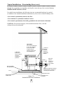
Typical Installations – Insert Stove
INSERT STOVE VENTED INTO
EXISTING CHIMNEY
RAIN CAP
The Quest insert may be installed in a masonry
or factory built fireplace as shown below. When
installing into the existing chimney, the exhaust
venting system should be extended to the top of
the chimney as shown below. However, if the
vent pipe cannot be run to the top of the chimney, the pipe must extend a minimum of 10
feet (3m) above the exhaust connection on the
stove and be sealed with a steel plate in the
damper area. Ensure that the end of any flex
pipe used in this type of installation is not
blocked, when terminated inside the existing
flue. Note: Any installation that does not run
all the way to the top of the chimney is not
recommended.
Seal chimney
top with
steel plate
and/or pipe
support
We also recommend that the fireplace cavity be
thoroughly cleaned and sealed with latex paint or
masonry sealer. The paint will seal in old soot
and creosote and help prevent fine dust from
being pulled into the stove's convection fan and
blown into the house.
IMPORTANT NOTE:
Make sure the chimney
and fireplace are clean
and free of soot and ashes
BEFORE installation
begins. Failure to do so
may result in the transfer
of soot into the room.
Optional
metal
Plate
8” Minimum
clearance
6” Minimum
clearance
Clean-out Tee
Removable
Clean-out
cup
32
Trouble Shooting
WARNING: Unplug stove from wall outlet before performing service work!
PROBLEM
Fire burns with a lazy orange
flame. Pellets build up in the
grate and soot forms on the
window.
CAUSE(S)
There is insufficient
combustion air.
SOLUTIONS
Remove any clinkers or ash from the
bottom of the grate that might be
obstructing the primary air passages
(between the rods).
Change to a better grade of fuel if
necessary.
Check that the damper has been
opened enough for the amount of
fuel feed.
Check that the heat exchange tubes
are not coated with ash.
Clean internal exhaust ducts.
Check gasket seal around the firebox
door (and ash pan areas on the freestanding stove). Use a thin strip of
paper, 1 in. wide, open the door and
close it on the paper strip. A slight
friction should be felt when the paper
strip is pulled. Repeat this process at
various locations around the door
gasket. Replace the door gasket
if necessary.
Check for blockage in the air inlet
duct or exhaust pipe. Clean as
necessary; empty the ash pan.
Close ash slide plates.
Have your Whitfield dealer check
your combustion blower.
Fire goes out or stove shuts
down automatically
The hopper is empty
Refill hopper.
Pellets are not feeding.
See (Pellets will not feed) below.
The high limit temperature
switch has tripped.
Allow stove to cool for 1 hour and relight. If the stove has been operating
at a medium to high burn rate and the
convection fan has been turned down
“LOW” then the fan should be
33
Trouble Shooting (cont.)
PROBLEM
Fire goes out or stove shuts
down automatically
CAUSE(S)
SOLUTIONS
The high limit temperature
switch has tripped.
turned up higher. If this problem persists (particularly at lower burn rates)
then the high-limit snap switch should
be replaced by your certified
Whitfield dealer.
There is too much combustion
air for the amount of fuel.
Adjust the damper to reduce combustion air flow.
The hopper is empty.
Refill hopper.
The auger motor or circuit
board may be defective. The
pressure switch tap or hose may
be blocked.
Check to be sure that there is no
blockage in the pressure tap or hose.
Have your certified Whitfield dealer
diagnose the problem and clean or
replace any necessary parts.
Auger jam
Check hopper or feed tube for foreign
object. Gently rock the auger motor
back and forth to release jammed pellets
The exhaust gases are not up to
temperature.
Press start switch and re-light stove
if necessary.
The low limit snap switch is not
operating correctly.
Have your certified Whitfield dealer
replace the low limit snap switch.
The wires to the low limit snap
switch are loose or
disconnected.
Check wires between the snap switch
and the wiring harness. Make sure that
there are good connections between
the wires and their terminals.
Fans will not shut off after
fuel has been switched off and
the stove has cooled down.
The low limit snap switch has
failed in the closed position.
Have your certified Whitfield dealer
replace the low limit snap switch.
Fans will not operate when
the start switch is depressed.
There is no power to the stove.
Check that the stove is plugged in to
the wall outlet.
Pellets will not feed.
Stove runs for 30 minutes
then shuts down.
Check to see if your circuit breaker
has tripped.
34
Trouble Shooting (cont.)
PROBLEM
CAUSE(S)
SOLUTIONS
Fans will not operate when
the start switch is depressed.
There is no power to the control
board.
Check the connections between the
high-limit snap switch and the
harness. Call your Whitfield Dealer
for a diagnosis.
There is soot or fly ash in the
house.
The window is being cleaned
when the stove is operating.
Turn down the convection fan or turn
off stove before cleaning to prevent
dispersion of ash and soot into the
room.
There is leakage at the joints
between the combustion fan,
exhaust pipe, and “L” vent. This
will be evidenced by dust on the
impeller of the convection fan,
and inside the heat exchanger
tubes.
Seal up any leaks in the exhaust system with room temperature
vulcanizing silicone sealer (RTV).
For a fireplace insert installation,
if existing fireplace opening was
not thoroughly cleaned and
sealed (painted) before the insert
was installed, the convection fan
may be picking up dust, soot or
ash and blowing it into the
house.
Pull the insert away from the fireplace
opening. Thoroughly clean the opening and paint the inside opening with
latex paint or masonry sealer to hold
down the finer particles of dust.
The stove is being cleaned with
an unapproved vacuum.
DO NOT use a standard household
vacuum or “shop vac” as the filters
will leak the fine particles of ash.
Clean the stove with an approved Ash
Vacuum ONLY.
No fuel supply.
Check to see that hopper contains fuel
and that auger is primed (full of fuel),
and fuel is feeding into the burn grate
(auger “on” light is blinking).
Insufficient combustion air flow.
Check to see that burn grate is firmly
in place, and that firebox door and ash
release slide plates are completely
closed. On freestanding model, ash
door must be latched. Fuel feed rate
and damper knobs should be set to the
“MEDIUM” and “HIGH” ranges.
With optional FASTFIRE™
Self-Igniter, pellets do not
ignite within 15 minute timer
cycle; igniter probe glows red.
35
Trouble Shooting (cont.)
PROBLEM
CAUSE(S)
With optional FASTFIRE™
Self-Igniter, pellets do not
ignite within 15 minute timer
cycle; igniter probe glows red.
Ash or pellet dust is blocking the
end of the igniter tube.
Clean igniter tube.
Stove has optional
FASTFIRE™ Self-Igniter, but
igniter probe does not heat up
(glow red) and ignite pellets.
No power to probe.
Check to see that the power cord is
plugged in. Contact your authorized
whitfield dealer if this is not the
source of the problem.
36
SOLUTIONS
Optional Accessories
● SHROUDS AND MAGNETIC SHROUD TRIM - Two sizes of shrouds and magnetic
shroud trim are available for the Quest insert stove:
Small: 28 1/2 inches(72.4 cm) high by 40 3/4 inches(l03.5 cm) wide
Large: 32 inches(81.3 cm) high by 44 inches(111.75 cm) wide
● INSERT PEDESTAL SUPPORT KIT - A pedestal support kit is available to provide
support for the front of the Quest insert. This kit is often used when the fireplace hearth
extension is lower than the floor of the firebox. The insert pedestal support attaches to and
supports the bottom front of the insert stove.
● GOLD-PLATED LOUVERS - are available to replace the standard painted louvers, which
cover the convection air outlet on factory model Quest stoves.
● INSERT CENTERING ADAPTER - An adapter for centering exhaust pipe on
insert installations.
● LOG SET - A two piece decorative log set is available.
● FASTFIRE™ SELF-IGNITER kits are available. This option allows you to light pellets
with push-button ease.
TO ORDER: Complete kits (including installation instructions) for any of the optional
accessories listed above may be ordered from your authorized Whitfield Pellet Stove dealer.
37
Pyro Industries, Inc.
Whitfield Quest Owner’s Manual
WP4PYROG97 Part No. 13627518
Serial Number 12140+
This Owner’s Manual and its contents are ©1995-97 Pyro Industries, Inc.
You may not reproduce this manual in any form
without written permission from Pyro Industries, Inc.
Contact us on our Website www.whitfield.com