1
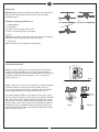
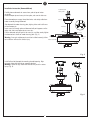
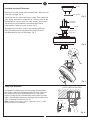
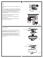
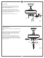
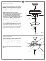
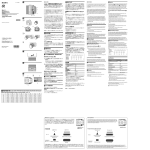
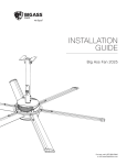
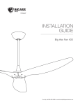
Owner’s Guide and Installation Manual
BF2-XX Series Fan
UL Model NO. : AC-552
Attach sales receipt to this card and retain as your proof of purchase
DATE OF PURCHASE:
RETAILER NAME:
MODEL NUMBER:
RETAILER ADDRESS:
To register your fixture, please visit our website www.montecarlofans.com
7.76 kgs
17.07 lbs
Total fan weight with light
Cautions and Warnings
WARNING: TO REDUCE THE RISK OF FIRE, ELECTRIC SHOCK, OR INJURY TO PERSONS, OBSERVE THE FOLLOWING
READ AND SAVE THESE INSTRUCTIONS
Installation work and electrical wiring must be done by qualified person(s) in accordance with applicable codes and standards (ANSI/NFPA
70-1999), including fire-rated construction.
Use this unit only in the manner intended by the manufacturer. If you have any questions contact the manufacturer.
After making the wire connections, the wires should be spread apart with the grounded conductor and the equipment-grounding conductor
on one side of the outlet box and ungrounded conductor on the other side of the outlet box. The splices, after being made, should be
turned upward and pushed carefully up into the outlet box.
WARNING: Before you begin installing the fan, servicing or cleaning unit, Switch power off at Service panel and lock service disconnecting
means to prevent power from being switched on accidentally. When the service disconnecting means cannot be locked, securely fasten a
prominent warning device, such as a tag, to the service panel.
Be cautious! Read all instructions and safety information before installing your new fan. Review the accompanying assembly diagrams.
When cutting or drilling into wall or ceiling, do not damage electrical wiring and other hidden utilities.
Make sure the installation site you choose allows the fan blades to rotate without any obstructions. Allow a minimum clearance of 7 feet
from the floor to the trailing edge of the blade.
WARNING: To Reduce The Risk Of Fire, Electric Shock, or Personal Injury, Mount To Outlet Box Marked “Acceptable for Fan Support of
15.9 kg (35 lbs) or less” And Use Mounting Screws Provided With The Outlet Box.
CAUTION: For Compliance with Local Codes and Regulations, If Installing The Secondary Support Safety Cable in the U.S., Do Not Remove
Knockouts In The Outlet Box. Mount the secondary support safety cable through the reserved nail/screw hole on the outlet box to the
building structure (or the ceiling joist).
WARNING: To reduce the risk of personal injury, do not bend blade holders during installation to motor, balancing or during cleaning. Do
not insert foreign object between rotating blades.
Attach the mounting bracket using only the hardware supplied with the outlet box.
WARNING: To reduce the risk of fire or electric shock, this fan must be installed with an isolating wall control/switch.
WARNING: To reduce the risk of fire or electric shock, do not use this fan with any unverified solid state fan speed control device, or
variable speed control.
If this unit is to be installed over a tub or shower, it must be marked as appropriate for the application.
Never place a switch where it can be reached from a tub or shower.
The combustion airflow needed for safe operation of fuel-burning equipment may be affected by this unit’s operation. Follow the heating
equipment manufacturer’s guideline safety standards such as those published by the National Fire Protection Association (NFPA), and the
American Society for Heating, Refrigeration and Air Conditioning Engineers (ASHRAE) and the local code authorities.
CAUTION: To Reduce the Risk of Electric Shock, Disconnect the electrical supply circuit to the fan before installing the light kit.
All set screws must be checked and tightened where necessary before installation.
Tools Required for Assembly (not included): Electrical Tape, Phillips Screwdriver, Pliers, Safety Glasses, Stepladder and Wire Strippers
Customer Service
800-969-3347
Customer Service Center
7400 Linder Ave.
Skokie, IL 60077
www.montecarlofans.com
© 2013 Monte Carlo Fan Company
2
3/8/2013
Preparation
Warning: Before starting assembly of this product, please disconnect
power to area and familiarize yourself with the safety information
provided on page 2.
A
Determine mounting method to use.
C
A - Downrod Mount
B - Angle Mount
Important: If using the angle mount, check
to make sure the ceiling angle is not steeper
B
than 18º.
Important: If using the angle mount, make sure open end of mounting
bracket is installed facing the higher point of the ceiling.
C - Flushmount
Note: Flushmount is not available with vaulted ceiling.
Installation Instruction
Before you begin installing the fan, Switch power off at Service panel
and lock service disconnecting means to prevent power from being
switched on accidentally. When the service disconnecting means cannot
be locked, securely fasten a warning device, such as a tag, to the
service panel. (Fig. 1)
ON
ON
OFF
OFF
Fig. 1
Before installing this fan make sure the outlet box is properly installed to
the house structure. To reduce the risk of fire, electric shock, or
personal injury, mount to outlet box or supporting system acceptable
for fan support (Mounting must support at least 35 lbs). (Fig. 2)
Use metal outlet box suitable for fan support and use only the screws
(and may be with flat washers and lock washers) provided with the outlet
box (must support 35 lbs). Before attaching fan to outlet box, ensure
the outlet box is securely fastened by at least two points to a structural
ceiling member (a loose box will cause the fan to wobble). Remove the
two outlet box screws provided with the box, aligning the holes of the
mounting bracket with the holes of the outlet box. Reinstall the 2 outlet
box screws securely. (Fig. 2-1)
© 2013 Monte Carlo Fan Company
3
Mounting
bracket
Fig. 2
Fig. 2-1
3/8/2013
Installation Instruction (Downrod Mount)
Lead wires and
Safety cable
Partially loosen downrod set screws from yoke at top of motor
assembly.
Remove keeper pin and cross pin from yoke, and save for later use.
Downrod
Place downrod over canopy, thread lead wires and safety cable from
motor assembly through downrod.
Canopy
Slip downrod into motor housing yoke, aligning holes and install cross
pin and keeper pin.
Insert cross pin through yoke and downrod until point appears on the
other side, and insert keeper pin on cross pin.
Pull the downrod up tight against the cross pin, and then evenly tighten
the downrod set screws on motor housing yoke. (Fig. 3)
Warning: Cross pin and keeper pin must be installed securely, failure
to install them will result in serious injury.
Downrod
Yoke
Set screw
Keeper
pin
Cross pin
Motor assembly
Fig. 3
Install ball end of downrod into mounting bracket opening. Align
(engage) slot on ball with tab on mounting bracket.
Warning: Failure to align slot on ball with tab may result in serious
injury. (Fig. 4)
Tab
Slot
Fig. 4
© 2013 Monte Carlo Fan Company
4
3/8/2013
Canopy
Installation Instruction (Flushmount)
Remove and set aside canopy cover to reveal 6 holes. Notice that 3 of
these holes are larger. (Fig. 5)
Canopy cover
Thread lead wires and safety cable through canopy. Place canopy over
yoke, aligning larger holes in canopy with the 3 existing screws on top
of motor housing. Install 3 screws and 3 lock washers (these screws
and lock washers will be located in the hardware pack) into the
remaining holes. Tighten all screws securely. (Fig. 6)
Fig. 5
Screw and
lock washer
Canopy
To prepare the fan for wiring, hang fan onto mounting bracket by
sliding the canopy over the mounting bracket hook (Use one of
non-slotted holes on the rim of the canopy). (Fig. 7)
Lead wires and
Safety cable
Yoke
Fig. 6
Hook
Fig. 7
Safety Cable Installation
SAFETY CABLE INSTALLATION
For Canadian installation and for USA fan and light kit combinations
over 35 lbs, in both flush and downrod modes the safety cable must
be installed into the house structure beams using 3” lag screws,
washers and lock washers provided. Make sure that when the safety
cable is fully extended the lead wires are longer than the cable and no
stress is placed on the lead wires. (Fig. 8)
Note: If Installing The Secondary Support Safety Cable in the U.S., Do Not
Remove Knockouts In The Outlet Box.
Lag screw
Safety cable
Washer
Lock washer
Fig. 8
© 2013 Monte Carlo Fan Company
5
3/8/2013
Wall Switch
White
Wiring
Power
Line
Black
Warning: Make sure main power is turned off before making
wiring.
Grounded/
Green
Black
Make wire connections as indicated. Connect Black and Blue
wire from fan to Black (Hot) wire from house. Connect White
wire from Fan to White (Neutral) wire from house. Connect all
green grounded wires from fan to Grounded wire from
House. Make sure that no filaments are outside of the wire
connectors. (Fig. 9)
Blue
White
Fig. 9
Fan
Light
Black
white
Grounding/Green
Note: Wrap each wire connector separately with electrical
tape as an extra safety measure.
Wall controller
Blue
Note: A professional electrician is recommended for this
type of installation.
Black
Wiring Option with Wall Controller
For control of fan and light separately from wall location,
follow diagram as shown. (Fig. 9-1)
Fig. 9-1
Power supply
Outlet box
Canopy Installation
Screws
Mounting bracket
Partially loosen 2 of the set screws on mounting bracket
corresponding to the slotted holes on the canopy upper ring.
Remove the other 2 set screws. Save screws.
Canopy
Raise canopy to mounting bracket, aligning loosened screws
in mounting bracket with slotted holes in canopy. Twist
canopy to lock. Reinstall screws (with washers) that were
previously removed and then tighten all screw securely. (Fig.
10, Fig. 10-1)
Fig. 10
Outlet box
Screws
Mounting bracket
Canopy
Fig. 10-1
© 2013 Monte Carlo Fan Company
6
3/8/2013
Blade installation
Install blade bracket with blade by 3 blade screws and
washers provided. Tighten screws securely. Repeat this
process for remaining blades. (Fig. 11)
Remove shipping stabilizers from motor assembly.
Install the blade assembly to motor using the preinstalled
screws. Tighten screws securely. Repeat this process for
remaining blade assemblies. (Fig. 11)
Screws
Fiber
washers
Note: Tighten blade bracket screws twice a year.
Screws
Blade
shipping stabilizers
Blades bracket
Fig. 11
Light fixture installation
Warning: Make sure main power is turned off before making
wiring.
Connect WHITE wire from switch housing to WHITE wire from
light fixture. Connect BLUE wire from switch housing to
BLACK wire from light fixture. Be sure plugs connections
snap together completely.
Remove the 3 set screws on top of light fixture, keep
screws. Align the slot on top of light fixture with the reverse
switch on switch housing, and then attach light fixture onto
switch housing. Reinstall the 3 set screws. Securely tighten
all 3 screws. (Fig. 12)
Wire connectors (plugs)
Light fixture
Slot
Switch
housing
Screws
Reverse switch
Fig. 12
© 2013 Monte Carlo Fan Company
7
3/8/2013
/2013
Light bulbs and glass installation
Install 2 x 60 watt candelabra base bulbs, Bulbs included.
WARNING: Over lamping the fan will result in the fan lights
shutting down until the proper wattage of bulbs are installed.
Reset the lights by turning off the wall switch, breaker,or by
remote. Replace bulbs with the correct wattage bulbs, turn
the power on.
Caution: Do not replace bulb until it cools down.
Remove finial, final cap and nut from light fixture. Raise glass
in order to guide pull chains through appropriate holes in
glass, aligning threaded rod on light fixture with hole in
middle of the glass and push up gently allowing threaded rod
to come through hole. (Noted: Be sure pull chain for fan
operation does not rub against bulb during operation).
Replace the nut on threaded rod, Tighten the nut but DO
NOT OVERTIGHTEN as glass may crack or break. Align hole
in center of final cap with thread rod, allowing pull chains to
come through appropriate holes in the final cap, and push
up. Thread center pull chain through hole in finial and secure
glass to light fixture by tightening the finial. DO NOT OVER
TIGHTEN the finial as glass may crack or break. (Fig. 13)
Light fixture
Pull chain
Bulbs
Glass
Install fan pull chain and light kit pull chain to preassembled
pull chains on fan and light fixture. Pull chains provided.
(Fig. 13)
Nut
Final cap
Finial
Fig. 13
Pull chains
Forward/Reverse switch setting
Setting the reverse switch in the down position will result in
downward airflow and setting the switch in the up position
will result in upward airflow.
Note: Reverse switch must be set either completely down
or completely up for fan to function. If the reverse switch is
set in the middle position, fan will not operate. (Fig. 14)
Operation and Maintenance
Refer to operation and maintenance on the second page of
parts list.
Reverse switch
Fig.14
© 2013 Monte Carlo Fan Company
8
3/8/2013
Trouble Shooting
,I\RXKDYHGLI¿FXOW\RSHUDWLQJ\RXUQHZFHLOLQJIDQLWPD\EHWKHUHVXOWRILQFRUUHFWDVVHPEO\LQVWDOODWLRQ
RUZLULQJ,QVRPHFDVHVWKHVHLQVWDOODWLRQHUURUVPD\EHPLVWDNHQIRUGHIHFWV,I\RXH[SHULHQFHDQ\IDXOWV
SOHDVHFKHFNWKLV7URXEOH6KRRWLQJ&KDUW,IDSUREOHPFDQQRWEHUHPHGLHGRU\RXDUHH[SHULHQFLQJGLI¿FXOW\LQ
LQVWDOODWLRQSOHDVHFDOORXU&XVWRPHU6HUYLFH&HQWHUDWWKH
QXPEHUSULQWHGRQ\RXUSDUWVOLVWLQVHUWVKHHW
Warning %HIRUH VHUYLFLQJ RU FOHDQLQJ XQLW 6ZLWFK SRZHU RII DW 6HUYLFH SDQHO DQG ORFN VHUYLFH GLVFRQQHFWLQJ
PHDQVWRSUHYHQWSRZHUIURPEHLQJVZLWFKHGRQDFFLGHQWDOO\:KHQWKHVHUYLFHGLVFRQQHFWLQJPHDQVFDQQRWEH
ORFNHGVHFXUHO\IDVWHQDSURPLQHQWZDUQLQJGHYLFHVXFKDVDWDJWRWKHVHUYLFHSDQHO
Trouble
Suggested Remedy
,IIDQGRHVQRWVWDUW
&KHFNPDLQDQGEUDQFKFLUFXLWIXVHVRUFLUFXLWEUHDNHUV
&KHFNOLQHZLUHFRQQHFWLRQVWRIDQDQGVZLWFKZLUHFRQQHFWLRQVLQVZLWFKKRXVLQJ
CAUTION0DNHVXUHPDLQSRZHULVWXUQHGRII
,IWKLVIDQXVHVPDQXDOIRUZDUGUHYHUVHVZLWFKPDNHVXUHWKHVZLWFKLVSXVKHG¿UPO\HLWKHU
ZD\)DQZLOOQRWRSHUDWHZKHQVZLWFKLVLQWKHPLGGOH
,IWKLVIDQXVHVUHPRWHFRQWUROOHUPDNHVXUHGLSVZLWFKHVDUHVHWWLQJSURSHUO\DQGPDNHVXUH
EDWWHU\LVHIIHFWLYH
,IIDQVRXQGVQRLV\
&KHFNWRPDNHVXUHDOOVFUHZVLQPRWRUKRXVLQJDUHVQXJQRWRYHUWLJKWHQHG
&KHFNWRPDNHVXUHWKHVFUHZVZKLFKDWWDFKWKHIDQEODGHKROGHUWRWKHPRWRUDUHWLJKW
&KHFNWRPDNHVXUHZLUHQXWFRQQHFWRUVLQVZLWFKKRXVLQJDUHQRWUDWWOLQJDJDLQVWHDFKRWKHU
RUDJDLQVWWKHLQWHULRUZDOORIWKHVZLWFKKRXVLQJ
CAUTION0DNHVXUHPDLQSRZHULVWXUQHGRIIEHIRUHHQWHULQJVZLWFKKRXVLQJ
&KHFNWREHVXUHOLJKWEXOELVWLJKWLQVRFNHWDQGQRWWRXFKLQJWKHJODVVVKDGH
6RPHIDQPRWRUVDUHVHQVLWLYHWRVLJQDOVIURP6ROLG6WDWHYDULDEOHVSHHGFRQWUROV
$OORZ EUHDNLQ SHULRG RI KRXUV 0RVW QRLVHV DVVRFLDWHG ZLWK D QHZ IDQ ZLOO GLVDSSHDU
DIWHUWKLVSHULRG
,IIDQZREEOHV
,IWKLVLVDGRZQURGPRXQWIDQPDNHVXUHWKHULGJHRQPRXQWLQJEUDFNHWHQJDJHVWKHQRWFKLQ
WKHGRZQURGEDOO
0DNHVXUHWKDWFDQRS\PRXQWLQJEUDFNHWRUPRXQWLQJSODWHDUHWLJKWHQHGVHFXUHO\WRFHLOLQJ
MXQFWLRQER[DQGMXQFWLRQER[LVPRXQWHG¿UPO\WRFHLOLQJMRLVW
&KHFNWKDWDOOEODGHVDUHVFUHZHG¿UPO\LQWREODGHKROGHUV
&KHFNWKDWDOOEODGHKROGHUVDUHWLJKWHQHGVHFXUHO\WRPRWRU
0RVW IDQ ZREEOH SUREOHPV DUH FDXVHG ZKHQ EODGH OHYHOV DUH XQHTXDO &KHFN WKLV OHYHO E\
VHOHFWLQJ DSRLQW RQ WKH FHLOLQJ DERYH WKH WLS RI RQH RI WKH EODGHV 0HDVXUHWKLV GLVWDQFH IURP
EODGHWLSWRFHLOQJ.HHSLQJPHDVXUHZLWKLQURWDWHWKHIDQXQWLOWKHQH[WEODGHLVSRVLWLRQHG
IRUPHDVXUHPHQW5HSHDWIRUHDFKEODGH,IDOOEODGHOHYHOVDUHQRWHTXDO\RXFDQDGMXVWEODGH
OHYHOV E\ WKH IROORZLQJ SURFHGXUH 7R DGMXVW D EODGH WLS GRZQ LQVHUW D ZDVKHU QRW VXSSOLHG
EHWZHHQWKHEODGHDQGEODGHKROGHUDWWKHVFUHZFORVHVWWRWKHPRWRU7RDGMXVWDEODGHWLSXS
LQVHUWZDVKHUQRWVXSSOLHGEHWZHHQWKHEODGHDQGEODGHKROGHUDWWKHWZRVFUHZVIDUWKHVWIURP
WKHPRWRU5HYHUVHWKHSRVLWLRQRIWKHZDVKHULIEODGHVPRXQWIURPWRSRIEODGH
,I EODGH ZREEOH LV VWLOO QRWLFHDEOH LQWHUFKDQJLQJ WZR DGMDFHQW VLGH E\ VLGH EODGHV FDQ
UHGLVWULEXWHWKHZHLJKWDQGSRVVLEO\UHVXOWLQVPRRWKHURSHUDWLRQ
,IOLJKWGRHVQRWZRUN &KHFNEOXHZLUHIURPIDQWRPDNHVXUHLWLVFRQQHFWHGWRKRWZLUHIURPKRXVH
&KHFNIRUORRVHRUGLVFRQQHFWHGZLUHVLQIDQVZLWFKKRXVLQJ
&KHFNIRUORRVHRUGLVFRQQHFWHGZLUHVLQOLJKWNLW
&KHFNIRUIDXOW\OLJKWEXOEDQGPDNHVXUHEXOELVWLJKWLQVRFNHW
5HPRYHOLJKWNLWDQGFKHFNWKHSOXJFRQQHFWLRQVLIWKH\DUHSUHVHQW
,IWKLVIDQXVHVUHPRWHFRQWUROOHUPDNHVXUHGLSVZLWFKHVDUHVHWWLQJSURSHUO\DQGPDNHVXUH
EDWWHU\LVHIIHFWLYH
CAUTION0DNHVXUHPDLQSRZHULVWXUQHGRIIEHIRUHHQWHULQJVZLWFKKRXVLQJDQGRUFDQRS\
WARNING2YHUODPSLQJWKHIDQZLOOUHVXOWLQWKHIDQOLJKWVVKXWWLQJGRZQXQWLOWKHSURSHU
ZDWWDJHRIEXOEVDUHLQVWDOOHG5HVHWWKHOLJKWVE\WXUQLQJRIIUHSODFHEXOEVZLWKWKHFRUUHFW
ZDWWDJHEXOEV7XUQSRZHURQ
© 2013 Monte Carlo Fan Company
9
3/8/2013
Mar. 2013
May.2013 CUL requirement