1
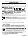
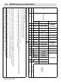
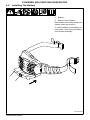
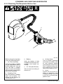
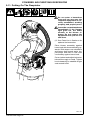
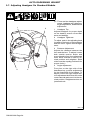
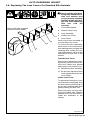
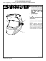
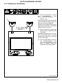
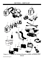
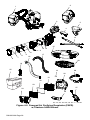
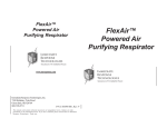
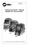
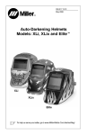
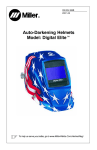
OM-235 936C
2011−02
®
Auto-Darkening Helmets
Model: Powered Air-Purifying
Respirator (PAPR)
To help us serve you better, go to www.MillerWelds.Com/HelmetReg/
805 068
TABLE OF CONTENTS
SECTION 1 − PAPR SAFETY PRECAUTIONS −READ BEFORE USING
1-1. Symbol Usage . . . . . . . . . . . . . . . . . . . . . . . . . . . . . . . . . . . . . . . . . . . . . . . . . . . . . . . . . . . .
1-2. Arc Welding Hazards . . . . . . . . . . . . . . . . . . . . . . . . . . . . . . . . . . . . . . . . . . . . . . . . . . . . . .
1-3. NIOSH Approval Information . . . . . . . . . . . . . . . . . . . . . . . . . . . . . . . . . . . . . . . . . . . . . . . .
1-4. Proposition 65 Warnings . . . . . . . . . . . . . . . . . . . . . . . . . . . . . . . . . . . . . . . . . . . . . . . . . . .
SECTION 2 − POWERED AIR-PURIFYING RESPIRATOR (PAPR)
2-1. Respirator Specifications . . . . . . . . . . . . . . . . . . . . . . . . . . . . . . . . . . . . . . . . . . . . . . . . . . .
2-2. Charging The Battery . . . . . . . . . . . . . . . . . . . . . . . . . . . . . . . . . . . . . . . . . . . . . . . . . . . . . .
2-3. Installing The Battery . . . . . . . . . . . . . . . . . . . . . . . . . . . . . . . . . . . . . . . . . . . . . . . . . . . . . .
2-4. Installing The Air Filter . . . . . . . . . . . . . . . . . . . . . . . . . . . . . . . . . . . . . . . . . . . . . . . . . . . . .
2-5. Attaching The Connecting Hose . . . . . . . . . . . . . . . . . . . . . . . . . . . . . . . . . . . . . . . . . . . . .
2-6. Operating The Controls . . . . . . . . . . . . . . . . . . . . . . . . . . . . . . . . . . . . . . . . . . . . . . . . . . . .
2-7. Testing Air Flow . . . . . . . . . . . . . . . . . . . . . . . . . . . . . . . . . . . . . . . . . . . . . . . . . . . . . . . . . . .
2-8. Testing Air Flow Alarm . . . . . . . . . . . . . . . . . . . . . . . . . . . . . . . . . . . . . . . . . . . . . . . . . . . . .
2-9. Installing Shoulder Strap . . . . . . . . . . . . . . . . . . . . . . . . . . . . . . . . . . . . . . . . . . . . . . . . . . .
2-10. Checking The Respirator Before Use . . . . . . . . . . . . . . . . . . . . . . . . . . . . . . . . . . . . . . . . .
2-11. Putting On The Respirator . . . . . . . . . . . . . . . . . . . . . . . . . . . . . . . . . . . . . . . . . . . . . . . . . .
2-12. Maintenance And Storage . . . . . . . . . . . . . . . . . . . . . . . . . . . . . . . . . . . . . . . . . . . . . . . . . .
2-13. Respirator Troubleshooting . . . . . . . . . . . . . . . . . . . . . . . . . . . . . . . . . . . . . . . . . . . . . . . . .
SECTION 3 − AUTO-DARKENING HELMET
3-1. Specifications . . . . . . . . . . . . . . . . . . . . . . . . . . . . . . . . . . . . . . . . . . . . . . . . . . . . . . . . . . . . . .
3-2. Helmet Controls . . . . . . . . . . . . . . . . . . . . . . . . . . . . . . . . . . . . . . . . . . . . . . . . . . . . . . . . . . . .
3-3. Reset Button And Low Battery Indicator . . . . . . . . . . . . . . . . . . . . . . . . . . . . . . . . . . . . . . . .
3-4. Lens Delay Control . . . . . . . . . . . . . . . . . . . . . . . . . . . . . . . . . . . . . . . . . . . . . . . . . . . . . . . . .
3-5. Variable Shade Control (No. 8 − 13) . . . . . . . . . . . . . . . . . . . . . . . . . . . . . . . . . . . . . . . . . . .
3-6. Sensitivity Control . . . . . . . . . . . . . . . . . . . . . . . . . . . . . . . . . . . . . . . . . . . . . . . . . . . . . . . . . .
3-7. Adjusting Headgear On Standard Models . . . . . . . . . . . . . . . . . . . . . . . . . . . . . . . . . . . . . . .
3-8. Replacing The Lens Covers On Standard Elite Helmets . . . . . . . . . . . . . . . . . . . . . . . . . . .
3-9. Replacing Grinding Shield On Titanium 9400i Helmet . . . . . . . . . . . . . . . . . . . . . . . . . . . . .
3-10. Replacing The Battery . . . . . . . . . . . . . . . . . . . . . . . . . . . . . . . . . . . . . . . . . . . . . . . . . . . . . .
3-11. Installing Optional Magnifying Lens . . . . . . . . . . . . . . . . . . . . . . . . . . . . . . . . . . . . . . . . . . .
3-12. Maintenance . . . . . . . . . . . . . . . . . . . . . . . . . . . . . . . . . . . . . . . . . . . . . . . . . . . . . . . . . . . . . .
3-13. Troubleshooting . . . . . . . . . . . . . . . . . . . . . . . . . . . . . . . . . . . . . . . . . . . . . . . . . . . . . . . . . . .
SECTION 4 − PARTS LIST
WARRANTY
1
1
1
4
5
6
6
7
8
9
10
11
12
13
14
15
16
17
17
19
19
20
21
21
22
23
24
25
26
27
28
28
29
30
SECTION 1 − PAPR SAFETY PRECAUTIONS −
READ BEFORE USING
PAPR 2010−03
Protect yourself and others from injury — read and follow these precautions.
1-1. Symbol Usage
DANGER! − Indicates a hazardous
situation which, if not avoided, will
result in death or serious injury. The
possible hazards are shown in the
adjoining symbols or explained in
the text.
Indicates special instructions.
Indicates a hazardous situation
which, if not avoided, could result in
death or serious injury. The possible
hazards are shown in the adjoining
symbols or explained in the text.
This group of symbols means Warning! Watch
Out! ELECTRIC SHOCK, MOVING PARTS,
and HOT PARTS hazards. Consult symbols
and related instructions below for necessary
actions to avoid the hazards.
NOTICE − Indicates statements not related to
personal injury.
1-2. Arc Welding Hazards
Only qualified persons should install, operate, maintain, and repair this unit.
ARC RAYS can burn eyes and skin.
Arc rays from the welding process produce intense visible and invisible (ultraviolet
and infrared) rays that can burn eyes and skin. Sparks fly off from the weld.
Wear a welding helmet fitted with a proper shade of filter to protect your face and eyes when
welding or watching (see ANSI Z49.1 and Z87.1 listed in Safety Standards). Refer to Shade
and Sensitivity charts.
Wear approved safety glasses with side shields under your helmet.
Use protective screens or barriers to protect others from flash, glare, and sparks; warn
others not to watch the arc.
Wear protective clothing made from durable, flame-resistant material (leather, heavy cotton,
and wool) and foot protection.
•
•
Before welding, adjust the auto-darkening lens sensitivity setting to meet the application.
Stop welding immediately if the auto-darkening lens does not darken when the arc is struck.
See the Owner’s Manual for more information.
WELDING HELMETS do not provide unlimited eye, ear and
face protection.
Arc rays from the welding process produce intense visible and invisible (ultraviolet
and infrared) rays that can burn eyes and skin. Sparks fly off from the weld.
Use impact resistant safety spectacles or goggles and ear protection at all times when using
this welding helmet.
Do not use this helmet while working with or around explosives or corrosive liquids.
Do not weld in the overhead position while using this helmet.
Inspect the auto-lens frequently. Immediately replace any scratched, cracked, or pitted cover
lenses or auto-lenses.
OM-235 936 Page 1
NOISE can damage hearing.
Noise from some processes or equipment can damage hearing.
Wear approved ear protection if noise level is high.
READ INSTRUCTIONS.
Read and follow all labels and the Owner’s Manual carefully before installing,
operating, or servicing unit. Read the safety information at the beginning of
the manual and in each section.
Use only genuine replacement parts from the manufacturer.
Perform maintenance and service according to the Owner’s Manuals, industry standards,
and national, state, and local codes.
FUMES AND GASES can be hazardous.
Welding produces fumes and gases. Breathing these fumes and gases can be
hazardous to your health.
Keep your head out of the fumes. Do not breathe the fumes.
If inside, ventilate the area and/or use local forced ventilation at the arc to remove welding
fumes and gases.
If ventilation is poor, wear an approved air-supplied respirator.
Read and understand the Material Safety Data Sheets (MSDSs) and the manufacturer’s
instructions for metals, consumables, coatings, cleaners, and degreasers.
Work in a confined space only if it is well ventilated, or while wearing an air-supplied respirator.
Always have a trained watchperson nearby. Welding fumes and gases can displace air and
lower the oxygen level causing injury or death. Be sure the breathing air is safe.
Do not weld in locations near degreasing, cleaning, or spraying operations. The heat and rays
of the arc can react with vapors to form highly toxic and irritating gases.
Do not weld on coated metals, such as galvanized, lead, or cadmium plated steel, unless the
coating is removed from the weld area, the area is well ventilated, and while wearing an airsupplied respirator. The coatings and any metals containing these elements can give off toxic
fumes if welded.
OM-235 936 Page 2
RESPIRATOR (PAPR) MISUSE can be hazardous.
Welding produces fumes and gases. Breathing these fumes and gases can be hazardous to your health.
Read and follow these instructions and the safety labels carefully. The powered air purifying
respirator (PAPR) helps protect the user from specific airborne contaminants but must be used
correctly to be fully effective. Have an industrial hygienist test the air in your facility to ensure
the PAPR provides adequate protection from contaminants in your environment. If you have
questions about the respirator, see equipment NIOSH label and consult your Safety Director
and an Industrial Hygienist.
Follow all applicable ANSI, OSHA, CSA, and other regulatory guidelines pertaining to the use
of respirators.
Do not use the powered air purifying respirator where there is danger of fire or explosion.
Do not use the powered air purifying respirator in windy conditions or negative pressure inside
the hood may draw in contaminants from the outside air.
Do not use the powered air purifying respirator without a properly installed spark guard. Without the spark guard, welding sparks may ignite the filter or damage the filters and allow unfiltered air into the helmet.
The powered air purifying respirator does not supply oxygen. Use the respirator only in atmospheres for which it is NIOSH approved. Do not use the respirator where oxygen levels are
19.5% or lower, where contaminant levels are unknown or are immediately dangerous to life or
health (IDLH), or where the contaminant levels exceed the respirator specifications.
Do not enter a hazardous area until you are sure the respirator equipment is correctly assembled, working properly, and properly worn.
Before each use, inspect the respirator equipment for damage and verify it operates properly.
Before using the respirator, test air flow to verify it is providing an adequate volume of air.
Do not use the powered air purifying respirator without all filter components or with the blower
turned off or hazardous levels of oxygen and carbon dioxide may accumulate in the helmet.
Always wear the powered air purifying respirator when entering a contaminated area. Do not
remove the respirator until outside the contaminated area.
Dangerous contaminants may not smell or be visible. Leave the area immediately if you notice
the following:
. . . Breathing becomes difficult.
. . . You experience dizziness, impaired vision, or eye, nose, or mouth irritation.
. . . The powered air purifying respirator alarm sounds.
. . . The equipment is damaged.
. . . Air flow decreases or stops.
. . . If you think the equipment is not supplying adequate protection.
Do not remove the equipment until you are in a safe area.
Do not repair, modify, or disassemble the powered air purifying respirator or use with parts or
accessories not supplied by the manufacturer. Use only NIOSH approved components.
Replace damaged or clogged filters. Do not wash or reuse filters. Do not clean filters by tapping
or with compressed air or filter elements may be damaged. Dispose of used filter elements
according to local, state, and federal requirements.
The powered air purifying respirator must be used with the helmet, hood, and filters recommended by the manufacturer to provide a NIOSH-approved respirator system. See the NIOSH
label for information on the required equipment.
Do not use the powered air purifying respirator belt and shoulder straps as a safety harness.
The powered air purifying respirator contains electrical parts which have not been evaluated as
an ignition source in flammable or explosive atmospheres by MSHA/NIOSH.
OM-235 936 Page 3
1-3. NIOSH Approval Information
PROTECTION1
HE
TC−
21C−0834
HE
X
X
235672
BLOWER
X
244131
BATTERY
X
X
247474
9400i HOSE
X
BELT
X
ABCFIJLMNOPS
ABCFIJLMNOPS
Caution and
Limitation 2
X
244151
X
BAG
BELT
EXTENSION
X
228028
2. CAUTIONS AND LIMITATIONS:
A − Not for use in atmospheres containing less than 19.5 percent oxygen.
B − Not for use in atmospheres immediately dangerous to life or health.
C − Do not exceed maximum use concentrations established by regulatory standards.
F − Do not use powered air−purifying respirators if airflow is less than four cfm (115 lpm) for tight fitting facepieces or six cfm (170 lpm) for hoods and/or helmets.
I − Contains electrical parts that may cause an ignition in flammable or explosive atmospheres.
J − Failure to properly use and maintain this product could result in injury or death.
L − Follow the manufacturer’s User’s Instructions for changing cartridges, canister and/or filters.
M − All approved respirators shall be selected, fitted, used, and maintained in accordance with MSHA, OSHA, and other applicable regulations.
N − Never substitute, modify, add, or omit parts. Use only exact replacement parts in the configuration as specified by the manufacturer
O − Refer to User’s Instructions, and/or maintenance manuals for information on use and maintenance of these respirators.
P − NIOSH does not evaluate respirators for use as surgical masks.
S − Special or critical User’s Instructions and/or specific use limitations apply. Refer to User’s Instructions before donning.
X
239571
HOSE COVER ACCESSORIES
X
235683
X
235680
X
CHARGER
SHOULDER
STRAPS
FLOW METER
(ELITE)
FLOW METER
(9400i)
X
244132
X
X
ELITE HOSE
X
X
235681
X
X
PREFILTER
X
X
235674
X
SPARK GUARD
X
235676
X
FILTER
X
235673
ALTERNATE
HOSE
ASSEMBLIES
235677
235679
245219
FILTER HOLDER
THIS RESPIRATOR IS APPROVED ONLY IN THE FOLLOWING CONFIGURATION:
9400i HELMET
X
X
247471
X
ELITE HELMET
1. PROTECTION:
HE−High Efficiency Particulate Air Filter for Powered, Air Purifying Respirators
21C−0877
237708
S − Special or critical User’s Instructions and/or specific use limitations apply. The Air Armor PAPR has been
manufactured by OTOS Tech. Co. Ltd. For Miller Electric Mfg. Co. under TC−21C−0834, TC−21C−0877
OM-235 936 Page 4
COMPONENT
ALTERNATE
HELMET
ASSEMBLIES
PART
NUMBER
1-4. Proposition 65 Warnings
Welding or cutting equipment produces fumes or gases which contain chemicals known
to the State of California to cause birth defects and, in some cases, cancer. (California
Health & Safety Code Section 25249.5 et seq.)
This product contains chemicals, including lead, known to the state of California to cause
cancer, birth defects, or other reproductive harm. Wash hands after use.
OM-235 936 Page 5
SECTION 2 − POWERED AIR-PURIFYING RESPIRATOR
(PAPR)
This equipment helps protect the user from certain contaminants. All users must read and
understand these instructions and be trained in the proper use of this equipment before
using. Use this equipment according to all applicable health and safety standards. If you
have questions about the type of respiratory equipment required, consult your safety director and an Industrial Hygienist.
Do not enter a hazardous area until you are sure the respirator equipment is correctly assembled, working properly, and properly worn.
See Section 3 for information on the auto-darkening helmet assembly.
The powered air-purifying respirator (PAPR) filters contaminated air and blows it into the
welding helmet hood through a flexible connecting hose. The respirator system generates a positive air pressure to help prevent contaminants from entering the hood. The
system must include and/or be used with the equipment listed below:
Helmet with auto-darkening lens, hood, and headgear system
Connecting hose
Blower assembly with filtration system (spark guard, foam prefilter, HEPA filter), and low
battery and low air flow alarms
Belt assembly
Air flow indicator
Battery charger
The respirator equipment operates at temperatures from 23° to 131° F and provides air
flow of 6+ CFM (low speed) to 7.06 CFM (high speed) under normal conditions. Battery
life is reduced when the unit is used in a dirty environment. If the system air flow decreases to an unsafe level, an alarm will sound, the blower vibrates, and the Danger light
will flash to warn the user to immediately leave the contaminated area. Use the supplied
air flow indicator to determine if the unit is supplying adequate amounts of clean air.
2-1. Respirator Specifications
Size (Blower Assembly)
9-1/2 x 8-1/4 x 3 in. (241 x 210 x 76 mm)
Weight
(Blower Assembly w/battery and filters)
33.2 oz. (941 g)
Standard Air Filter
NIOSH-approved filter assembly consisting of a spark
guard screen, foam prefilter, and particulate (HEPA)
filter.
Approved to filter particulate down to 0.3 micrometers
in size.
Air Flow
Low Speed: 6+ CFM (170+ LPM) minimum
High Speed: 7.06 CFM (200 LPM)
Operating Temperature
23° to 131° F (−5° to 55° C)
Storage Temperature
14° to 176° F (−10° to 80° C)
Battery Type
Rechargeable Lithium
Battery Charging Time
About Three hours
Battery Life
500 charges
Run time dependent on air flow rate and filter load.
Belt size
28 to 55 in. (711 to 1397 mm)
OM-235 936 Page 6
POWERED AIR PURIFYING RESPIRATOR
2-2. Charging The Battery
3
2
.
Charge battery only with
supplied charger in an open,
well−ventilated location.
.
Do not allow battery to get
wet. Do not attempt to open
the battery case.
.
Keep battery away from fire
or heat.
.
Charge battery before first
use or if battery has not been
used for five days.
Dispose of battery at a designated collection facility.
Battery charging
stops when
battery is fully charged.
1
Battery Terminal
2
120 Volt AC Battery Charger
3
120 Volt AC Receptacle
Remove battery from blower assembly. Connect charger cord to
battery terminal. Connect charger
to 120 volt AC receptacle.
1
The charger red light goes on when
battery is being charged. When fully charged, the charger green light
goes on. Charging normally takes
about four hours.
If
red light flashes during
charging, stop charging for 30
minutes then charge battery an
additional 20 minutes (green
light will be on).
805 099
OM-235 936 Page 7
POWERED AIR PURIFYING RESPIRATOR
2-3. Installing The Battery
1
Battery
2
Battery Unlock Button
Slide battery into blower body until
battery snaps into position.
To remove battery, push battery unlock button down and pull battery
from blower assembly.
1
2
Ref. 805 068
OM-235 936 Page 8
POWERED AIR PURIFYING RESPIRATOR
2-4. Installing The Air Filter
1
2
3
4
.
Do not use the respirator
without the spark guard
screen, foam prefilter, and
particulate (HEPA) filter
installed.
.
Replace damaged or dirty air
filters. Do not wash filters,
clean with compressed air,
or reuse dirty air filters.
Dispose of used filters at a designated collection facility.
1
Particulate (HEPA) Filter
2
Foam Prefilter
3
Spark Guard Screen
4
Cover
Install the screen, prefilter, and particulate filter in cover exactly as
shown.
Install the filter assembly by sliding
the tabs on the cover into the bracket on the blower body; push down
on the filter until it “clicks” into position.
Ref. 805 096
OM-235 936 Page 9
POWERED AIR PURIFYING RESPIRATOR
2-5. Attaching The Connecting Hose
Ref. 805 068 / 805 098
Screw Connector
Tab Connector
1
OR
.
Be sure connecting hose is
properly installed or contaminated air may enter the helmet.
Connecting Hose To Blower
Align pins on hose connector (blower
end) with channels in blower receptacle. Insert hose connector into
blower receptacle until snug and
then turn connector 1/8
turn clockwise.
Connecting Hose To Helmets
Equipped With Screw Connector
Insert hose connector (helmet end)
into hood receptacle. Turn hose connector collar clockwise until tight.
Connecting Hose To Helmets
Equipped With Tab Connector
1
Locking Tab
Push hose connector (rectangular
end) into helmet air inlet until hose
locks in position. (Locking tab should
be on outside of helmet air inlet.
Do not insert hose locking tab in-
to helmet inlet. Locking tab
should be on outside of helmet
air inlet.
OM-235 936 Page 10
POWERED AIR PURIFYING RESPIRATOR
2-6. Operating The Controls
.
3
4
5
6
2
1
Leave the contaminated area immediately if the Danger light
goes On, the alarm
sounds, or the blower
vibrates. Do not remove the equipment
until you are in a safe
area.
1
On Button
2
Off Button
3
Danger Indicator
4
Low Speed Indicator
5
High Speed Indicator
6
Battery Level Indicator
Indicator lights
are al-
ways red.
To Start: Press On button
for 1−2 seconds until the
blower starts. The Danger
indicator lights and then
goes out, the alarm sounds,
and the blower vibrates momentarily.
The blower always starts at
the low speed. Press the On
button to switch between
High and Low speeds.
To Stop: Press Off button
for 2 − 3 seconds until the
audible alarm and blower
stop.
The Danger indicator light
goes on, the alarm sounds,
and the blower vibrates if
battery power is low or air
flow is reduced due to a dirty
filter, blocked hose, or other
problem. See Section 2-13,
Troubleshooting.
The Battery Level indicator
lights show the power remaining in the battery. When
all three lights are on the battery is fully charged.
Ref 805 068
OM-235 936 Page 11
POWERED AIR PURIFYING RESPIRATOR
2-7. Testing Air Flow
.
1
MIN
Always test air flow before
using the respirator. Also
check air flow each month if
respirator is not used regularly.
1
Flowmeter
2
Hose Connector (Hood)
Disconnect hose from hood. Insert
flowmeter into hose. Be sure hose
is straight and untwisted. Hold flowmeter straight up and start blower.
Air flow is adequate if flowmeter ball
moves above MIN mark. Do not
use respirator if flowmeter reads
MIN or below. If air flow is low,
check battery and filter elements
and recheck air flow.
2
805 098 / 805 101
OM-235 936 Page 12
POWERED AIR PURIFYING RESPIRATOR
2-8. Testing Air Flow Alarm
.
Always test air flow alarm
before using the respirator.
Also check air flow alarm
each month if respirator is
not used regularly.
Disconnect hose from hood. Start
blower and block air flow by placing
your hand over the end of the hose.
Continue blocking air flow until
alarm sounds and the blower vibrates (about 15 to 20 seconds).
If alarm does not sound and the
blower does not vibrate, check battery and filter element.
805 101
OM-235 936 Page 13
POWERED AIR PURIFYING RESPIRATOR
2-9. Installing Shoulder Strap
1
Shoulder Strap
2
Snap
3
Link
Connect snaps on shoulder straps
to links on belt.
1
2
3
805 068
OM-235 936 Page 14
POWERED AIR PURIFYING RESPIRATOR
2-10. Checking The Respirator Before Use
6
5
2
1
3
805 068
Before using the respirator,
check the following items:
1 Air Filter Assembly
Verify the air filter is suitable
for the application and is
NIOSH-approved. Also be
sure the filter is undamaged, properly assembled,
and securely connected to
the blower assembly.
2 Breathing Tube
Be sure the tube is undamaged and properly connected to the blower assembly and hood.
3
Battery
Verify the battery is fully
charged and securely connected to the blower assembly.
4
Air Flow (Not Shown)
Test air flow according to
Section 2-7.
5 Air flow Alarm
Turn on blower assembly
and check for audible, visual, and vibratory alarms
(see Sections 2-6 and 2-8).
See Troubleshooting section if alarms go on at any
other time (Section 2-13).
6 Hood
Inspect the hood and replace if damaged. See
Troubleshooting (Section
2-13) if air is not being supplied to hood.
OM-235 936 Page 15
POWERED AIR PURIFYING RESPIRATOR
2-11. Putting On The Respirator
.
Do not enter a hazardous
area until you are sure the
respirator equipment is correctly assembled, working
properly, and properly worn.
.
Leave the contaminated area
immediately if the Danger
light goes On, the alarm
sounds, or the blower vibrates. Do not remove the
equipment until you are in a
safe area.
See Parts List in Section 4 for
optional belt extension.
Place blower assembly against
lower back with hose extending upwards. Slide straps over shoulders
and fasten belt around waist. Adjust straps and belt so unit rests
comfortably against lower back.
Put on helmet and adjust helmet so
helmet fits snugly on head. Tighten
hood drawstring to establish a tight
seal around head.
805 187
OM-235 936 Page 16
POWERED AIR PURIFYING RESPIRATOR
2-12. Maintenance And Storage
Replace damaged or dirty air filters. Do not wash filters, clean with compressed air, or
reuse dirty air filters.
Never use solvents or abrasive cleaning solutions to clean the respirator. Keep water and
other fluids out of blower assembly.
Maintain accurate records of filter replacement and respirator maintenance.
For best performance clean the equipment after each use. Use a soft cloth
dampened with a mild soap and water solution to wipe all external surfaces
clean. Allow to air dry.
Product usage, workplace contamination levels, and other factors affect the life
of the filter elements. Replace filter elements if air flow is reduced due to a dirty
filter (see Section 2-4) and according to the filter change schedule established
by your Safety Director and an Industrial Hygienist.
Inspect connecting hose and replace if damaged or if inside of tube is dirty.
If the respirator will not be used for an extended period, remove the filter and
battery and store them in a clean, dry, cool place free of solvent-based vapors.
2-13. Respirator Troubleshooting
Trouble
Blower does not supply air
to hood.
Remedy
Press On button.
Dead battery; recharge battery (see Section 2-2).
Verify battery is properly connected to blower body.
Remove blockage from blower outlet and hose.
Blower cannot be turned
Off.
Press Off button for two to three seconds.
Blower runs for short time Be sure battery is properly connected to battery charger.
even though battery is fully
charged.
Replace battery.
Replace charger.
Battery warning light is On
and alarm sounds.
Continue wearing the respirator and leave the contaminated area
immediately. Charge or replace the battery. The blower will operate for about 20 minutes after the warning light goes on.
Have Safety Director and an Industrial Hygienist determine if you
are using the proper equipment for the work environment.
OM-235 936 Page 17
POWERED AIR PURIFYING RESPIRATOR
Battery run time is too
short.
Replace battery.
Check air filter and replace if necessary (see Sections 2-4 and
2-7). A clogged air filter element reduces battery life.
Danger light is On, alarm
sounds or blower vibrates.
Continue wearing the respirator and leave the contaminated area
immediately. Check blower air flow (see Sections 2-4 and 2-7).
Remove blockage from blower outlet and/or hose. If alarm sounds
or blower vibrates continuously, contact a Factory Authorized
Service Agent.
Remove packaging from air filter.
Have Safety Director and an Industrial Hygienist determine if you
are using the proper equipment for the work environment.
Air supplied to hood
smells and tastes unusual;
eyes and throat irritation.
Continue wearing the respirator and leave the contaminated area
immediately. Check contamination level of filter, and replace filter
if necessary.
Check hose connections to blower and hood.
Verify spark guard, prefilter, and particulate (HEPA) filter are
installed in blower assembly.
Have Safety Director and an Industrial Hygienist determine if you
are using the proper equipment for the work environment.
Blower supplies insufficient air to hood.
Check hose connections to blower and hood.
Remove blockage from blower outlet and/or hose.
Check air filter and replace if necessary (see Sections 2-4 and
2-7). A clogged air filter element reduces battery life.
OM-235 936 Page 18
SECTION 3 − AUTO-DARKENING HELMET
See Section 2 for information on the powered air-purifying respirator (PAPR) assembly.
3-1. Specifications
Viewing Field
97 x 60mm/3.81 x 2.62 in
Reaction Time
0.0000500sec (1/20,000)
Available Shades
Darkened State: No. 8 − No. 13 / Light State: No. 3
provides continuous UV and IR protection
Sensitivity/Grind Mode Control
Adjusts for varying ambient light and welding arc
Delay Control
Slows lens dark-to-light state between 0.1 and
1.0 seconds
Automatic Power Off
Shuts lens Off 15−20 minutes after last arc is struck
Low Battery Indicator
Red LED light illuminates to indicate 2−3 days
remaining battery life
Power Supply
CR2450 Lithium Batteries (Miller Part No. 217 043)
Sensors
Independent/Redundant (Four)
Operating Temperature
14F to 131F / −10C to +55C
When stored in extremely cold temperatures, warm
helmet to ambient temperature before welding.
Storage Temperature
−4F to 158F / −20C to +70C
When stored in extremely cold temperatures, warm
helmet to ambient temperature before welding.
Total Weight
510.3g (1lb 2oz.)
Standards
ANSI Z87.1+(2003) and DIN/CSA/TUV
Warranty
2 years from date of purchase (see Section 5)
OM-235 936 Page 19
AUTO-DARKENING HELMET
3-2. Helmet Controls
1
2
3
4
5
4
2
1
5
Reset Button (See Section
3-3)
Low Battery Indicator
(See Section 3-3)
Variable Shade Control (See
Section 3-5)
Sensitivity Control
(See Section 3-6)
Lens Delay Control
(See Section 3-4)
3
OTOS
OM-235 936 Page 20
AUTO-DARKENING HELMET
3-3. Reset Button And Low Battery Indicator
The auto-darkening lens turns on
(darkens) automatically when
welding begins and turns off 15 −
20 minutes after welding stops.
1 Reset Button
Press Reset button to check if the lens
is working properly.
When the Reset button is pressed, the
lens should darken twice and return to
the clear state. Do not use the helmet
if the lens does not function as described. (See Section 3-13, Troubleshooting.)
2
2
Low Battery Indicator
The low battery indicator lights when
2−3 days of battery life remain.
If battery power is low, replace with
CR2450 lithium batteries (2 required)
(Miller Part No. 217 043) (see Section
3-10).
1
3-4. Lens Delay Control
1
Lens Delay Control
The lens delay control is used to
adjust the time for the lens to switch
to the clear state after welding.
The delay is particularly useful in
eliminating bright after-rays present in higher amperage applications where the molten puddle remains bright momentarily after
welding. Lens delay adjusts from
min (0.10 second) to max (1.0 second.).
1
OM-235 936 Page 21
AUTO-DARKENING HELMET
3-5. Variable Shade Control (No. 8 − 13)
1
Variable Shade Control
(No. 8 − 13)
Use the control to adjust the lens
shade in the darkened state. Use
the table below to select proper
shade control setting based on
your welding process.
Start at shade 12 and adjust lighter
to suit the welding application and
your personal preference.
1
Application Welding
Arc Current in Amperes
Protective Shade No.
Stick Electrodes
Less than 40
40−80
80−175
175−300
300−500
9
10
11
12
13
MIG
Less than 100
100−175
175−300
300−500
10
11
12
13
Gas Tungsten Arc Welding
(TIG)
Less than 50
50−100
100−200
200−400
10
11
12
13
Air Carbon
Less than 500
500−700
12
13
Plasma Arc Cutting
60−150
150−250
250−400
11
12
13
Plasma Arc Welding
Less than 50
50−200
200−400
9
10
12
OM-235 936 Page 22
AUTO-DARKENING HELMET
3-6. Sensitivity Control
1
Sensitivity Control
Weld Mode
Use control to make the lens more responsive to different light levels in various welding processes. Use a Mid-Range or
30−50% sensitivity setting for most applications.
It may be necessary to adjust helmet sensitivity to accommodate different lighting conditions or if lens is flashing On and Off. Adjust helmet sensitivity as follows:
Adjust helmet sensitivity in lighting conditions helmet will be used in.
Turn sensitivity control to lowest
setting.
Press Reset button to turn helmet On.
Helmet lens will darken twice and then
clear.
1
Face the helmet in the direction of use,
exposing it to the surrounding light conditions.
Gradually turn sensitivity setting clockwise until the lens darkens, then turn
sensitivity control counterclockwise
until slightly past setting where lens
clears. Helmet is ready for use. Slight
readjustment may be necessary for
certain applications or if lens is flashing
on and off.
Grind Mode
Do not weld in the Grind mode; the lens
will not darken.
To use the Grind mode, turn the Sensitivity
control clockwise to the far right position
(Grind). To resume welding, return the control to the desired sensitivity setting.
Recommended Sensitivity Settings
Stick Electrode
Mid-Range
Short Circuiting (MIG)
Low/Mid-Range
Pulsed & Spray (MIG)
Mid-Range
Gas Tungsten Arc (TIG)
Mid/High-Range
Plasma Arc Cutting/Welding
Low/Mid-Range
Grind Mode
Grind Position − Far Right (Clockwise)
OM-235 936 Page 23
AUTO-DARKENING HELMET
3-7. Adjusting Headgear On Standard Models
There are four headgear adjust-
ments: headgear top, tightness,
angle adjustment, and distance
adjustment.
1
3
1
Headgear Top
Adjusts headgear for proper depth
on the head to ensure correct balance and stability.
2
Headgear Tightness
To adjust, push in the adjusting knob
located on the back of the headgear
and turn left or right to desired tightness.
3
Distance Adjustment
Adjusts the distance between the
face and the lens. To adjust, loosen
both outside tension knobs and
press inward to free from adjustment
slots. Move forward or back to desired position and retighten. (Both
sides must be equally positioned for
proper vision.)
4
2
4
Angle Adjustment
Four pins on the right side of the
headband top provide adjustment
for the forward tilt of the helmet. To
adjust, loosen the right outside tension adjustment knob then lift on the
control arm tab and move it to the desired position. Retighten tension adjustment knob.
804 118
OM-235 936 Page 24
AUTO-DARKENING HELMET
3-8. Replacing The Lens Covers On Standard Elite Helmets
.
Be sure flat side of gasket
faces lens cover holder.
5
4
3
2
1
Never use the auto-darkening lens without the inside and outside lens
covers properly installed.
Welding spatter will damage the auto-darkening
lens and void the
warranty.
1
Front Lens Gasket
2
Outside Lens Cover
3
Lens Assembly
4
Inside Lens Cover
5
Lens Frame
Remove the lens assembly to
remove either lens cover.
To remove the lens assembly,
push down on the helmet bottom retaining arms and push the
retaining clips toward the outside of the helmet. Lift up on the
assembly and pull free of the
helmet.
Outside Lens Cover
Remove the outside lens cover
by pushing into the helmet. Remove the rubber lens gasket
and install on the new lens cover. Reinstall the lens assembly.
Be sure the flat side of lens
cover gasket faces the lens
cover holder.
Inside Lens Cover
To replace the inside lens cover,
remove the lens assembly from
the lens frame by pushing up on
the top two retaining tabs while
gently pushing the lens free.
Remove the lens cover by sliding it out of either side. Replace
with the new cover lens and reinstall the assembly in the
helmet.
Ref. 804 109
OM-235 936 Page 25
AUTO-DARKENING HELMET
3-9. Replacing Grinding Shield On Titanium 9400i Helmet
.
Never use the auto-darkening lens without the inside and outside lens
covers properly installed.
Welding spatter will damage the auto-darkening
lens and void the
warranty.
1
Grinding Shield
2
Retaining Clip
3
Tab
Rotate both retaining clips to the
Open position.
2
1
Gently push shield toward bottom tab and remove shield from
helmet.
Remove retaining clips from
shield. Install clips in same location on new shield. (Retaining
clips are not interchangeable.)
Install new shield in helmet and
rotate clips to the Lock position.
3
Ref. 804 109
OM-235 936 Page 26
AUTO-DARKENING HELMET
3-10. Replacing The Battery
To replace the batteries, remove
the
auto-darkening
lens
assembly (see Section 3-8).
1
1
Battery Tray
After removing the lens assembly,
slide the battery holding trays out
and remove the old batteries.
+
+
Be sure Positive
(+) side of battery
faces up.
Replace with CR2450 lithium type
batteries (2 required) or equivalent
(Miller Part No. 217043).
Be sure Positive (+) side of the
battery faces up (toward inside
of helmet).
Reinstall the battery trays. To test,
press the Reset button. The lens
should flash dark twice. Reinstall
the lens assembly.
Left and right battery trays are
not interchangeable. The
auto−darkening helmet will not
work if battery trays are
installed on the wrong sides.
OTOS / 804 847
OM-235 936 Page 27
AUTO-DARKENING HELMET
3-11. Installing Optional Magnifying Lens
1
1
Optional Magnifying Lens
Starting at the bottom, slide magnifying lens into the helmet retaining
brackets. Align the magnifying lens
with the auto-darkening lens assembly.
Remove lens holding frame
(with auto-darkening lens)
from helmet shell.
Remove auto-darkening
lens from lens holder.
Position lens holder with
magnifying lens holding
tabs facing toward you.
From the bottom up, slide
magnifying lens into position. (Slide magnifying lens
up or down slightly as desired.)
Reinstall the auto-darkening
lens in the lens holder.
Reverse procedure to remove magnifying lens.
To prevent lens fogging, install
flat side of magnifying lens toward auto-darkening lens.
804 818
3-12. Maintenance
NOTICE − Never use solvents or abrasive cleaning detergents. Do not immerse the lens assembly
in water.
The helmet requires little maintenance. However, for best performance clean
after each use. Using a soft cloth dampened with a mild soap and water solution,
wipe the cover lenses clean. Allow to air dry. Occasionally, the filter lens and
sensors should be cleaned by gently wiping with a soft, dry cloth.
OM-235 936 Page 28
AUTO-DARKENING HELMET
3-13. Troubleshooting
Trouble
Remedy
Auto lens not ON – autolens will not darken momentarily when the Reset
button is pressed.
Check batteries and verify they are in good condition and installed
properly. Also, check battery surfaces and contacts and clean if
necessary. Check battery for proper contact and gently adjust
contact points if necessary. This is particularly important if the
helmet has been dropped. Verify left and right battery trays are
installed on the correct sides.
Not switching – auto-lens
stays light and will not
darken when welding.
Stop welding immediately: Press the Reset button if lens is AutoOn type. If lens if Manual-On type, make sure the lens is turned
On. If power is on, review the sensitivity recommendations and
adjust sensitivity. Clean lens cover and sensors of any obstructions. Make sure the sensors are facing the arc; angles of 45 or
more may not allow the arc light to reach the sensors.
Not Switching – auto-lens
stays dark after the weld
arc is extinguished, or the
auto-lens stays dark when
no arc is present.
Fine-tune the sensitivity setting by making small adjustments to
the control by turning it toward the “min” setting. In extreme light
conditions, it may be necessary to reduce the surrounding light
levels.
Sections of the auto-lens
are not going dark, distinct
lines separate the light and
dark areas.
Stop welding immediately: The auto-lens may be cracked which
can be caused by the impact of dropping the helmet. Weld spatter
on the auto lens may also cause cracking. (The lens may need to
be replaced; most cracked lenses are not covered by warranty).
Switching or Flickering –
the auto-lens darkens then
lightens while the welding
arc is present.
Review the sensitivity setting recommendations and increase the
sensitivity if possible. Be sure the arc sensors are not being
blocked from direct access to the arc light. Check the lens cover
for dirt and spatter that may be blocking the arc sensors. Increasing Lens Delay 0.1 − 0.3 second may also reduce switching.
Inconsistent or lighter
auto-lens shading in the
dark-state, noticeable on
the outside edges and corners.
Referred to as an angle of view effect, auto-darkening lenses
have an optimum viewing angle. The optimum viewing angle is
perpendicular or 90 to the surface of the auto-lens. When that
angle of view varies in the dark-state, welders may notice slightly
lighter areas at the outside edges and the corners of the lens. This
is normal and does not represent any health or safety hazard.
This effect may also be more noticeable in applications where
magnifying lenses are used.
OM-235 936 Page 29
SECTION 4 − PARTS LIST
2
1
3
5
4
9
8
7
6
12
11
13
14
10
15
Î
Î
17
16
28
24
27
18
19
20
21
22
26
23
25
805 193 / Ref. 805 068
Figure 4-1. Powered Air Purifying Respirator (PAPR) w/Standard Elite
Helmet
OM-235 936 Page 30
Item
No.
Part
No.
Description
Quantity
Figure 4-1. Powered Air Purifying Respirator (PAPR)
w/Standard Elite Helmet
1 . . . . . . . . . . . . 235671 . . . . . . . . . PAPR (Complete System) . . . . . . . . . . . . . . . . . . . . . . . . .
. . . . . . . . . . . . . . 237811 . . . . . . . . . PAPR (System Without Auto-Dark Lens Assembly) . . . .
2 . . . . . . . . . . . . 237708 . . . . . . . . . Helmet Assembly (Includes Headgear And Head Seal .
3 . . . . . . . . . . . . 235685 . . . . . . . . . Headgear (Includes) . . . . . . . . . . . . . . . . . . . . . . . . . . . . . .
. . . . . . . . . . . . . . 079975 . . . . . . . . . . . Replacement O-rings For Kit 770 248 (5 Per Pkg.) . .
. . . . . . . . . . . . . . 770249 . . . . . . . . . . . Fabric Headband . . . . . . . . . . . . . . . . . . . . . . . . . . . . . .
4 . . . . . . . . . . . . 770248 . . . . . . . . . Adjustment Angle/Stop Hardware Kit (with O-rings) . . . .
5 . . . . . . . . . . . . 235684 . . . . . . . . . Head Seal (Hood) . . . . . . . . . . . . . . . . . . . . . . . . . . . . . . . .
6 . . . . . . . . . . . . 237451 . . . . . . . . . Helmet Shell, Black Elite w/Velcro® Fastening . . . . . . . .
7 . . . . . . . . . . . . 216337 . . . . . . . . . Gasket, Front Lens . . . . . . . . . . . . . . . . . . . . . . . . . . . . . . .
8 . . . . . . . . . . . . 216326 . . . . . . . . . Outside Lens Cover (4-11/16 X 5-5/8) (5 Per Pkg.) . . . .
9 . . . . . . . . . . . . 216328 . . . . . . . . . Auto-darkening Lens Assembly . . . . . . . . . . . . . . . . . . . .
10 . . . . . . . . . . . 216339 . . . . . . . . . Battery Tray Kit (Left/Right) . . . . . . . . . . . . . . . . . . . . . . . .
. . . . . . . . . . . . . . 217043 . . . . . . . . . Battery, (Lens) Lithium CR2450 . . . . . . . . . . . . . . . . . . . .
11 . . . . . . . . . . . 216327 . . . . . . . . . Inside Lens Cover (4-1/4 X 2-1/2) (5 Per Pkg.) . . . . . . . .
12 . . . . . . . . . . . 216335 . . . . . . . . . Frame, Lens . . . . . . . . . . . . . . . . . . . . . . . . . . . . . . . . . . . .
. . . . . . . . . . . . . ♦212235 . . . . . . . . Lens, 0.75 Magnification (Not Shown) . . . . . . . . . . . . . . .
♦212236 . . . . . . . . Lens, 1.00 Magnification (Not Shown)
♦212237 . . . . . . . . Lens, 1.25 Magnification (Not Shown)
. . . . . . . . . . . . . ♦212238 . . . . . . . . Lens, 1.50 Magnification (Not Shown)
. . . . . . . . . . . . . ♦212239 . . . . . . . . Lens, 1.75 Magnification (Not Shown)
. . . . . . . . . . . . . ♦212240 . . . . . . . . Lens, 2.00 Magnification (Not Shown)
. . . . . . . . . . . . . ♦212241 . . . . . . . . Lens, 2.25 Magnification (Not Shown)
. . . . . . . . . . . . . ♦212242 . . . . . . . . Lens, 2.50 Magnification (Not Shown)
1
1
1
1
1
1
1
1
1
1
1
1
1
2
1
1
1
.............
............... 1
.............
............... 1
............... 1
............... 1
............... 1
............... 1
...............
13 . . . . . . . . . . . 235680 . . . . . . . . . Shoulder Straps . . . . . . . . . . . . . . . . . . . . . . . . . . . . . . . . .
14 . . . . . . . . . . . 235679 . . . . . . . . . Belt . . . . . . . . . . . . . . . . . . . . . . . . . . . . . . . . . . . . . . . . . . . .
15 . . . . . . . . . . . 235683 . . . . . . . . . Flowmeter . . . . . . . . . . . . . . . . . . . . . . . . . . . . . . . . . . . . . .
16 . . . . . . . . . . . 235681 . . . . . . . . . Hose Assembly . . . . . . . . . . . . . . . . . . . . . . . . . . . . . . . . . .
17 . . . . . . . . . . . 239571 . . . . . . . . . Cover, Hose . . . . . . . . . . . . . . . . . . . . . . . . . . . . . . . . . . . .
18 . . . . . . . . . . . 237452 . . . . . . . . . O-Ring, Breathing Tube . . . . . . . . . . . . . . . . . . . . . . . . . . .
19 . . . . . . . . . . . 235672 . . . . . . . . . Blower Assembly . . . . . . . . . . . . . . . . . . . . . . . . . . . . . . . .
20 . . . . . . . . . . . 235673-2 . . . . . . . Filter, Particulate (HEPA) (2-Pack) . . . . . . . . . . . . . . . . . .
. . . . . . . . . . . . . . 235673-6 . . . . . . . Filter, Particulate (HEPA) (6-Pack) . . . . . . . . . . . . . . . . . .
. . . . . . . . . . . . . . 235673-36 . . . . . . Filter, Particulate (HEPA) (36-Pack) . . . . . . . . . . . . . . . . .
21 . . . . . . . . . . . 235674 . . . . . . . . . Filter, Prefilter (Foam) . . . . . . . . . . . . . . . . . . . . . . . . . . . .
22 . . . . . . . . . . . 235676 . . . . . . . . . Spark Guard . . . . . . . . . . . . . . . . . . . . . . . . . . . . . . . . . . . .
23 . . . . . . . . . . . 235677 . . . . . . . . . Filter Cover . . . . . . . . . . . . . . . . . . . . . . . . . . . . . . . . . . . . .
24 . . . . . . . . . . . 228028 . . . . . . . . . Bag . . . . . . . . . . . . . . . . . . . . . . . . . . . . . . . . . . . . . . . . . . . .
25 . . . . . . . . . . . 244131 . . . . . . . . . Battery, Blower . . . . . . . . . . . . . . . . . . . . . . . . . . . . . . . . . .
26 . . . . . . . . . . . 244132 . . . . . . . . . Charger . . . . . . . . . . . . . . . . . . . . . . . . . . . . . . . . . . . . . . . .
27 . . . . . . . . . . ♦244151 . . . . . . . . Belt Extension . . . . . . . . . . . . . . . . . . . . . . . . . . . . . . . . . . .
28 . . . . . . . . . . . 239636 . . . . . . . . . Belt Pad (PAPR) . . . . . . . . . . . . . . . . . . . . . . . . . . . . . . . . .
♦Optional
1
1
1
1
1
1
1
1
1
1
1
1
1
1
1
1
1
1
1
OM-235 936 Page 31
2
1
3
5
4
14
15
12 13
11
6
7
8
16
9
Î
Î
10
17
18
29
25
19
28
20
21
22
23
27
24
26
805 193 / Ref. 805 068 / Ref. 804 111 / 242 385
Figure 4-2. Powered Air Purifying Respirator (PAPR)
w/Titanium 9400i Helmet
OM-235 936 Page 32
Item
No.
Part
No.
Description
Quantity
Figure 4-2. Powered Air Purifying Respirator (PAPR) w/Titanium
9400i Helmet
1 . . . . . . . . . . . . 247531 . . . . . . . . . PAPR (Complete System) . . . . . . . . . . . . . . . . . . . . . . . . .
. . . . . . . . . . . . . . 247532 . . . . . . . . . PAPR (System Without Auto-Dark Lens Assembly) . . . .
2 . . . . . . . . . . . . 247471 . . . . . . . . . Helmet Assembly (Includes Headgear And Head Seal .
3 . . . . . . . . . . . . 247472 . . . . . . . . . Headgear Gray (Includes) . . . . . . . . . . . . . . . . . . . . . . . . .
4 . . . . . . . . . . . *770248 . . . . . . . . . . . Kit, Adjustment Angle/Stop Hardware . . . . . . . . . . . . .
. . . . . . . . . . . . . . 770249 . . . . . . . . . . . Headband, Fabric . . . . . . . . . . . . . . . . . . . . . . . . . . . . . .
. . . . . . . . . . . . . . 079975 . . . . . . . . . Replacement O-rings For Kit 770 248 (5 Per Pkg.) . . . .
5 . . . . . . . . . . . . 247473 . . . . . . . . . Head Seal (Hood) . . . . . . . . . . . . . . . . . . . . . . . . . . . . . . . .
6 . . . . . . . . . . . . 245815 . . . . . . . . . Lens Holder, Front (Titaniumi) . . . . . . . . . . . . . . . . . . . . . .
7 . . . . . . . . . . . . 216326 . . . . . . . . . Lens Cover, Outside (4-11/16 X 5-5/8) (5 Per Pkg.) . . .
8 . . . . . . . . . . . . 241977 . . . . . . . . . Gasket, Lens Assembly . . . . . . . . . . . . . . . . . . . . . . . . . . .
9 . . . . . . . . . . . . 245817 . . . . . . . . . Lens Assembly, Auto-Darkening . . . . . . . . . . . . . . . . . . . .
. . . . . . . . . . . . . . 217043 . . . . . . . . . Battery, Lithium (CR2450) . . . . . . . . . . . . . . . . . . . . . . . . .
10 . . . . . . . . . . . 216327 . . . . . . . . . Lens Cover, Inside 4-1/4 X 2-1/2 (5 Per Pkg.) . . . . . . . . .
11 . . . . . . . . . ♦212235 . . . . . . . . . Lens, 0.75 Magnification . . . . . . . . . . . . . . . . . . . . . . . . . .
♦212236 . . . . . . . . . Lens, 1.00 Magnification
. . . . . . . . . . . . ♦212237 . . . . . . . . . Lens, 1.25 Magnification
. . . . . . . . . . . . ♦212238 . . . . . . . . . Lens, 1.50 Magnification
. . . . . . . . . . . . ♦212239 . . . . . . . . . Lens, 1.75 Magnification
. . . . . . . . . . . . ♦212240 . . . . . . . . . Lens, 2.00 Magnification
. . . . . . . . . . . . ♦212241 . . . . . . . . . Lens, 2.25 Magnification
. . . . . . . . . . . . ♦212242 . . . . . . . . . Lens, 2.50 Magnification
............
1
1
1
1
1
1
1
1
1
1
1
1
2
1
1
.......................... 1
.......................... 1
.......................... 1
.......................... 1
.......................... 1
.......................... 1
..........................
12 . . . . . . . . . . . 245818 . . . . . . . . . Lens, Gringing Shield . . . . . . . . . . . . . . . . . . . . . . . . . . . . .
13 . . . . . . . . . . . 245819 . . . . . . . . . Clip, Retaining Grinding Shield . . . . . . . . . . . . . . . . . . . . .
14 . . . . . . . . . . . 235680 . . . . . . . . . Shoulder Straps . . . . . . . . . . . . . . . . . . . . . . . . . . . . . . . . .
15 . . . . . . . . . . . 235679 . . . . . . . . . Belt . . . . . . . . . . . . . . . . . . . . . . . . . . . . . . . . . . . . . . . . . . . .
16 . . . . . . . . . . . 245219 . . . . . . . . . Flowmeter . . . . . . . . . . . . . . . . . . . . . . . . . . . . . . . . . . . . . .
17 . . . . . . . . . . . 247474 . . . . . . . . . Hose Assembly . . . . . . . . . . . . . . . . . . . . . . . . . . . . . . . . . .
18 . . . . . . . . . . . 239571 . . . . . . . . . Cover, Hose . . . . . . . . . . . . . . . . . . . . . . . . . . . . . . . . . . . .
19 . . . . . . . . . . . 237452 . . . . . . . . . O-Ring, Breathing Tube . . . . . . . . . . . . . . . . . . . . . . . . . . .
20 . . . . . . . . . . . 235672 . . . . . . . . . Blower Assembly . . . . . . . . . . . . . . . . . . . . . . . . . . . . . . . .
21 . . . . . . . . . . . 235673-2 . . . . . . . Filter, Particulate (HEPA) (2-Pack) . . . . . . . . . . . . . . . . . .
. . . . . . . . . . . . . . 235673-6 . . . . . . . Filter, Particulate (HEPA) (6-Pack) . . . . . . . . . . . . . . . . . .
. . . . . . . . . . . . . . 235673-36 . . . . . . Filter, Particulate (HEPA) (36-Pack) . . . . . . . . . . . . . . . . .
22 . . . . . . . . . . . 235674 . . . . . . . . . Filter, Prefilter (Foam) . . . . . . . . . . . . . . . . . . . . . . . . . . . .
23 . . . . . . . . . . . 235676 . . . . . . . . . Spark Guard . . . . . . . . . . . . . . . . . . . . . . . . . . . . . . . . . . . .
24 . . . . . . . . . . . 235677 . . . . . . . . . Filter Cover . . . . . . . . . . . . . . . . . . . . . . . . . . . . . . . . . . . . .
25 . . . . . . . . . . . 228028 . . . . . . . . . Bag . . . . . . . . . . . . . . . . . . . . . . . . . . . . . . . . . . . . . . . . . . . .
26 . . . . . . . . . . . 244131 . . . . . . . . . Battery, Blower . . . . . . . . . . . . . . . . . . . . . . . . . . . . . . . . . .
27 . . . . . . . . . . . 244132 . . . . . . . . . Charger . . . . . . . . . . . . . . . . . . . . . . . . . . . . . . . . . . . . . . . .
28 . . . . . . . . . ♦244151 . . . . . . . . . Belt Extension . . . . . . . . . . . . . . . . . . . . . . . . . . . . . . . . . . .
29 . . . . . . . . . . . 239636 . . . . . . . . . Belt Pad (PAPR) . . . . . . . . . . . . . . . . . . . . . . . . . . . . . . . . .
♦Optional
1
1
1
1
1
1
1
1
1
1
1
1
1
1
1
1
1
1
1
1
1
OM-235 936 Page 33
SECTION 5 − LIMITED WARRANTY
LIMITED WARRANTY – Subject to the terms and conditions below. Miller
Electric Mfg. Co., Appleton, Wisconsin, warrants to its original retail purchaser that the new Miller equipment sold after the effective date of this
limited warranty is free of defects in material and workmanship at the time
it is shipped by Miller. THIS WARRANTY IS EXPRESSLY IN LIEU OF ALL
OTHER WARRANTIES, EXPRESS OR IMPLIED, INCLUDING THE
WARRANTIES OR MERCHANTABILITY AND FITNESS.
Miller Elite and Titanium Series auto-darkening lens helmets are warranted for two years from the date of purchase. The blower assembly is
warranted for one year from the date of purchase. The battery is warranted for six months from the date of purchase. Proof of purchase is required
for warranty transactions so it is imperative that a copy of the original invoice or sales receipt be retained.
For warranty transactions, contact your Miller Distributor.
Effective January 1, 2011
OM-235 936 Page 2
Visit our website at
www.MillerWelds.com
®
Miller Electric Mfg. Co.
An Illinois Tool Works Company
1635 West Spencer Street
Appleton, WI 54914 USA
ORIGINAL INSTRUCTIONS − PRINTED IN USA
© 2011 Miller Electric Mfg. Co.