1
P/N 47008
Rev. B V1 11/01
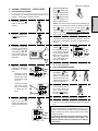
Combinations:
PS555E Electric
PS555G Gas
PS570G Gas
Single Oven
Double Oven (Two-Stack)
Triple Oven (Three-Stack)
Quad Oven (Four-Stack)
página 85
ESPAÑOL
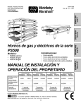
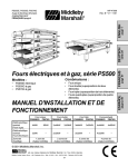
Models:
OWNER'S OPERATING AND
INSTALLATION MANUAL
Single Oven
PS555E/G PS570G
Double Oven
PS555E/G PS570G
Triple Oven
PS555E/G PS570G
Quad Oven
PS555E/G PS570G
Rated Heat Input
Gas Ovens
44kW
50kW
2x44kW
2x50kW
3x44kW
3x50kW
4x44kW
4x50kW
Rated Heat Input
Electric Ovens
32kW
--
2x32kW
--
3x32kW
--
4x32kW
--
Heating Zones
1 controlled
heat zone
2 controlled
heat zones
© 2001 Middleby Marshall, Inc.
is a registered trademark of Middleby Marshall, Inc. All rights reserved.
Middleby Cooking Systems Group 1400 Toastmaster Drive Elgin, IL 60120 USA (847)741-3300 FAX (847)741-4406
1
3 controlled
heat zones
page 57
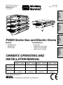
PS500 Series Gas and Electric Ovens
FRANÇAIS
seite 29
DEUTSCH
page 1
ENGLISH
PS555E, PS555G, PS570G
Gas and Electric (Europe)
ENGLISH/German/
French/Spanish
4 controlled
heat zones
NOTICE:
This Owner's Operating and Installation Manual should be given to the user. The operator of the oven should
be familiar with the functions and operation of the oven.
This manual must be kept in a prominent, easily reachable location near the oven.
ENGLISH
Gas ovens are designed for use with EITHER natural gas OR liquid propane gas, as specified on the serial plate.
Where permitted by local and national codes, the oven can be converted from natural gas to propane operation,
or from propane to natural gas operation. This conversion is described in the Installation section of this Manual.
The conversion requires the installation of the appropriate Middleby Marshall Gas Conversion Kit.
It is suggested to obtain a service contract with a Middleby Marshall Authorized Service Agent.
WARNING
POST, IN A PROMINENT LOCATION, THE EMERGENCY TELEPHONE NUMBER OF YOUR LOCAL GAS
SUPPLIER AND INSTRUCTIONS TO BE FOLLOWED IN THE EVENT YOU SMELL GAS.
Instructions to be followed in the event the user smells gas shall be obtained by consulting the local gas
supplier. If the smell of gas is detected, immediately call the emergency phone number of your local Gas
Company. They will have personnel and provisions available to correct the problem.
FOR YOUR SAFETY
Do not store or use gasoline or other flammable vapors or liquids in the vicinity of
this or any other appliance.
WARNING:
Improper installation, adjustment, alteration, service or maintenance
can cause property damage, injury or death. Read the installation,
operating and maintenance instructions thoroughly before installing
or servicing this equipment.
IMPORTANT
An electrical wiring diagram for the oven is located inside the machinery
compartment.
IMPORTANT
It is the customer's responsibility to report any concealed or non-concealed damage
to the freight company. Retain all shipping materials until it is certain that the
equipment has not suffered concealed shipping damage.
NOTICE: CONTACT YOUR MIDDLEBY MARSHALL AUTHORIZED SERVICE AGENT TO PERFORM MAINTENANCE
AND REPAIRS. AN AUTHORIZED SERVICE AGENCY DIRECTORY IS SUPPLIED WITH YOUR OVEN.
NOTICE: Using any parts other than genuine Middleby Marshall factory manufactured parts relieves the manufacturer of
all warranty and liability.
NOTICE: Middleby Marshall (Manufacturer) reserves the right to change specifications at any time.
NOTICE: The equipment warranty is not valid unless the oven is installed, started and demonstrated under the supervision
of a factory certified installer.
Retain This Manual For Future Reference
Middleby Cooking Systems Group 1400 Toastmaster Drive Elgin, IL 60120 USA (847)741-3300 FAX (847)741-4406
24-Hour Service Hotline: 1-(800)-238-8444
www.middleby.com
2
page
page
SECTION 1 - DESCRIPTION ................................................... 4
VII. GAS SUPPLY .......................................................... 11
I.
OVEN USES ............................................................. 4
A.
Connection ...................................................... 11
II.
OVEN COMPONENTS ............................................. 4
B.
Preparation for Use with Various Gases ....... 12
A.
Conveyor Drive Motor ....................................... 4
C. Replacing the Gas Orifices ............................. 12
B.
Crumb Pans ..................................................... 4
D. Checking the Gas Supply (Inlet) Pressure .... 13
C. Conveyor End Stop ........................................... 4
E.
D. Conveyor Rear Stop ......................................... 4
E.
Conveyor ........................................................... 4
F.
End Plugs ......................................................... 4
SECTION 3 - OPERATION ..................................................... 14
I.
G. Eyebrows .......................................................... 4
H. Window ............................................................. 4
I.
Serial Plate ....................................................... 4
J.
Machinery Compartment Access Panel .......... 4
K.
Control Panel .................................................... 4
L.
Gas Burner or Heating Elements .................... 4
B.
General Specifications ..................................... 4
II.
III.
C. Electrical Specifications for Electric Ovens ..... 4
Gas Orifice and Pressure Specifications ........ 5
BASE PAD KIT .......................................................... 6
II.
INSTALLATION KIT .................................................. 7
III.
VENTILATION SYSTEM ........................................... 7
A.
Requirements .................................................. 7
B.
Recommendations .......................................... 7
B.
Restraint Cable Installation ............................. 8
) Switch ....................................... 14
E.
Conveyor Speed Controller ............................. 14
F.
Digital Temperature Controller ....................... 14
NORMAL OPERATION, STEP-BY-STEP ................ 15
A.
Daily Startup Procedures ................................ 15
B.
Daily Shutdown Procedures ........................... 15
QUICK REFERENCE: DIGITAL TEMP CONTROL . 16
MAINTENANCE - DAILY .......................................... 18
II.
MAINTENANCE - MONTHLY .................................. 19
III.
MAINTENANCE - EVERY 3 MONTHS .................... 20
KEY SPARE PARTS KIT ......................................... 22
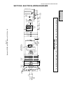
SECTION 5 - ELECTRICAL WIRING DIAGRAMS ................... 23
C. Conveyor Installation ........................................ 8
V.
) Switch ............................ 14
I.
V.
IV. ASSEMBLY ............................................................... 8
Base Pad, Legs, Casters, and Stacking ......... 8
) Switch ......................................... 14
IV. MAINTENANCE - EVERY 6 MONTHS .................... 21
C. Other Ventilation Concerns .............................. 7
A.
"HEAT" (
SECTION 4 - MAINTENANCE ................................................. 18
SECTION 2 - INSTALLATION .................................................. 5
I.
B.
) Switch ................................... 14
IV. QUICK REFERENCE: TROUBLESHOOTING ....... 17
D. Electrical Specifications for Gas Ovens .......... 5
E.
"BLOWER" (
G. Machinery Cpt. Access Panel Safety Switch .. 14
OVEN SPECIFICATIONS ......................................... 4
Dimensions ...................................................... 4
A.
D. "RESET" (
N. Air Fingers ........................................................ 4
A.
LOCATION AND DESCRIPTION OF CONTROLS . 14
C. "CONVEYOR" (
M. Blowers ............................................................. 4
III.
Adjusting the Orifice (Manifold) Pressure
and Heat Input ................................................. 13
FINAL ASSEMBLY ................................................... 10
VI. ELECTRICAL SUPPLY ........................................... 10
I.
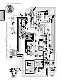
SCHEMATIC, PS555G OR PS570G GAS
OVEN, 230V, 50 Hz, 1 Ph ........................................ 23
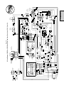
II.
WIRING DIAGRAM, PS555G OR PS570G
GAS OVEN WITH TYPE 1 GAS VALVE,
230V, 50 Hz, 1 Ph ................................................... 24
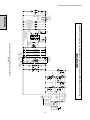
III.
WIRING DIAGRAM, PS555G OR PS570G
GAS OVEN WITH TYPE 2 GAS VALVE,
230V, 50 Hz, 1 Ph ................................................... 25
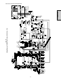
IV. SCHEMATIC, PS555E ELECTRIC OVEN,
380V, 50 Hz, 3 Ph ................................................... 26
V.
3
WIRING DIAGRAM, PS555E ELECTRIC
OVEN, 380V, 50 Hz, 3 Ph ........................................ 27
ENGLISH
TABLE OF CONTENTS
SECTION 1 - DESCRIPTION
I.
ENGLISH
OVEN USES
K.
PS500 Series Ovens can be used to bake and/or cook a
wide variety of food products, such as pizza, pizza-type
products, cookies, sandwiches and others.
Not Shown:
Control Panel: Location of the operating controls for the
oven. Refer to Section 3, Operation, for details.
L.
Gas Burner (gas ovens) or Heating Elements (electric
ovens): Heat air, which is then projected to the air fingers
by the blowers.
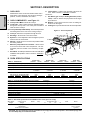
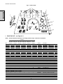
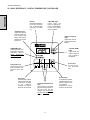
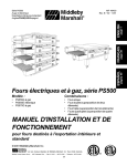
II. OVEN COMPONENTS - see Figure 1-1.
A.
Conveyor Drive Motor: Moves the conveyor.
B.
Crumb Pans: Catch crumbs and other material that drop
through the conveyor belt. One crumb pan is located at
each end of the conveyor.
M. Blowers: Project hot air from the burner or heating elements to the air fingers.
N.
Air Fingers: Project streams of hot air onto the food product.
C,D. Conveyor End Stop and Rear Stop: Prevents food products
from falling off the end or rear of the moving conveyor.
G
E.
Conveyor: Moves the food product through the oven.
F.
End Plugs: Allow access to the oven's interior.
G.
Eyebrows: Can be adjusted to various heights to prevent
heat loss into the environment.
H.
Window: Allows the user to access food products inside
the baking chamber.
I.
Machinery Compartment Access Panel: Allows access
to the oven's interior and control components. No userservicable parts are located in the machinery compartment.
J.
Figure 1-1 - Oven Components
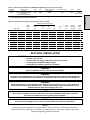
Table 1-1: Dimensions
D
H
I
J
Serial Plate: Provides specifications for the oven that affect
installation and operation. Refer to Section 2, Installation,
for details.
III. OVEN SPECIFICATIONS
F
B
C
E
K
A
Single Oven
PS555E/G
PS570G
Double Oven
PS555E/G
PS570G
Triple Oven
PS555E/G
PS570G
Quad Oven
PS555E/G
PS570G
Overall Height (inc. top and legs, as appropriate)
1.17m
1.53m
1.59m
1.98m
Overall Depth (inc. rear shrouds)
1.61m
1.61m
1.61m
1.61m
Overall Length
2.31m
Conveyor Width
2.69m
2.31m
2.69m
2.31m
2.69m
2.31m
2.69m
0.81m
or 2x0.38m
0.81m
or 2x0.38m
0.81m
or 2x0.38m
0.81m
or 2x0.38m
0 mm
0 mm
0 mm
0 mm
0 mm
0 mm
0 mm
0 mm
Recommended Minimum Clearances
Rear of Oven (inc. rear shrouds) to Wall
Conveyor Extension to Wall (both ends)
Table 1-2: General Specifications (per oven cavity)
Weight
Shipping Weight
Shipping Cube
Rated Heat Input - Gas Ovens
Rated Heat Input - Electric Ovens
Maximum Operating Temperature
Air Blowers
Average Air Jet Velocity
Warmup Time
PS555E/G
PS570G
533kg
590kg
568kg
624kg
4.53m3
4.53m3
44 kW, 37,800 kcal
50 kW, 42,840 kcal
32kW
-< - - - - - - - - - - - - 288°C - - - - - - - - - - - - >
Two blowers at 39.6m3/min. at 2050 RPM, 10mm Water Static Pressure
< - - - - - - - 13.20m/sec. average - - - - - - - >
< - - - - - - - - - - - - 15 min. - - - - - - - - - - - - >
Table 1-3: Electrical specifications for PS555E electric ovens (per oven cavity)
Main Blower
Voltage
Control Circuit
Voltage
Phase
Freq
380V
120V conveyor speed controller
(w/transformer);
all other control circuits 230V
3 Ph
50Hz
L1
48.6A
Current draw (avg.) *
L2
L3
48.6A
57.8A
N
9.2A
Poles
Wires
4 Pole
5 Wire
(3 hot, 1 neutral,
1 ground)
* CAUTION: The current draw shown in the chart above is an average value for normal operation. The initial amperage draw
on oven startup may exceed the listed value.
4
Main Blower
Voltage
230V
Control Circuit
Voltage
120V conveyor speed controller
(w/transformer);
all other control circuits 230V
Phase
Freq
1 Ph
50Hz
Electrical system
kW rating
2.3kW
Current draw (avg.) *
Poles
Wires
10A *
2 Pole
3 Wire
(2 hot, 1 gnd)
* CAUTION: The current draw shown in the chart above is an average value for normal operation. The initial amperage draw
on oven startup may exceed the listed value.
Table 1-5: Gas orifice and pressure specifications (per oven cavity)
Supply (inlet) Pressure (mbar)
PS555G
PS570G
Gas Type
Main
Orifice
dia.
Pilot
Orifice
dia.
IE,IT,PT,
ES,GB
II2H3+
NL
II2L3B/P
BE,FR
II2E+3+
AT,CH,DK,
FI,SE
II2H3B/P
II2ELL3B/P
Natural, G20
5.79mm
0.635mm
20
Natural, G25
5.79mm
0.635mm
--
20
--
20-25
20
25
--
Natural, G20, G25
5.79mm
0.635mm
20
20
25
20-25
DE
Orifice
(manifold)
pressure
Rated
Heat
Input
20
9.0 mbar
44kw
--
12.0 mbar
44kw
20
9.0 mbar
44kw
44kw
Liquid, G30
3.33mm
0.381mm
29-37
--
28-30
29-37
50
23.9 mbar
Liquid, G30, G31
3.33mm
0.381mm
--
50
30
--
50
23.9 mbar
44kw
Natural, G20
6.35mm
0.635mm
20
20
--
20-25
20
9.0 mbar
50kw
Natural, G25
6.35mm
0.635mm
--
20
25
--
--
12.0 mbar
50kw
Natural, G20, G25
6.35mm
0.635mm
20
20
25
20-25
20
9.0 mbar
50kw
Liquid, G30
3.53mm
0.381mm
29-37
--
28-30
29-37
50
23.9 mbar
50kw
Liquid, G30, G31
3.53mm
0.381mm
--
50
30
--
50
23.9 mbar
50kw
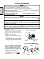
SECTION 2 - INSTALLATION
WARNING - After any conversions, readjustments, or service work on the oven:
Perform a gas leak test.
Test for correct air supply, particularly to the burner blower.
Test for proper combustion and gas supply.
Check that the ventilation system is in operation.
WARNING
Keep the appliance area free and clear of combustibles.
WARNING
The oven must be installed on an even (level) non-flammable flooring and any adjacent walls must be nonflammable. Recommended minimum clearances are specified in the Description section of this Manual.
WARNING
Do not obstruct the flow of combustion and ventilation air to and from your oven. There must be no
obstructions around or underneath the oven. Constructional changes to the area where the oven is
installed shall not affect the air supply to the oven.
NOTE
There must be adequate clearance between the oven and combustible construction. Clearance
must also be provided for servicing and for proper operation.
NOTE
An electrical wiring diagram for the oven is located inside the machinery compartment.
NOTE
All aspects of the oven installation, including placement, utility connections, and ventilation requirements,
must conform with any applicable local, national, or international codes. These codes supercede the requirements and guidelines provided in this manual.
5
ENGLISH
Table 1-4: Electrical specifications for PS555G and PS570G gas ovens (per oven cavity)
SECTION 2 - INSTALLATION
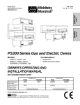
Fig. 2-1 - Base Pad Kit
1
8
ENGLISH
7
2
6
4a
9
13
11
10
4b
3
5b
12
5a
4c
I.
BASE PAD KIT - see Figure 2-1
NOTE: One Base Pad Kit is required for each Single, Double, Triple, or Quad Oven installation.
Quantity
Item
1a
1b
1c
1d
2
3
4a
4b
4c
5a
5b
6
7
8
---------
Single oven Double oven Double oven Triple oven
with 0.48m with 0.25m with 0.38m with 0.10m
extensions extensions extensions extensions
4
-----4
--4
-1
1
1
2
8
16
16
16
----
-4
----4
--4
-1
1
1
2
8
16
16
16
----
--4
---4
--4
-1
1
1
2
8
16
16
16
----
Triple oven
without leg
extensions
Quad oven
with
outriggers
Part No.
---4
--4
--4
-1
1
1
2
8
16
16
16
----
------4
--4
-1
1
1
2
8
-------
----4
4
-2
2
-4
1
1
1
2
8
8
8
8
16
32
16
37210-0060
37210-0082
37210-0057
39684
45209
45205
37115-0102
45357
45664
22450-0028
45206
22450-0253
21392-0005
41643
41582
21256-0069
21216-0018
21416-0003
21426-0004
A27727
A21924
21172-0004
Leg extension, 0.48m
Leg extension, 0.25m
Leg extension, 0.38m
Leg extension, 0.10m
Outrigger
Spacer, caster - for use with outrigger only
Caster, swivel (with stud)
Caster, swivel (with flat plate)
Caster, swivel (with flat plate and brake)
Adjustable foot, standard
Adjustable foot, quad ovens
Restraint cable, 1.5m
Eye bolt/lag screw
Base pad
Top cover (right or left)
Screw, sl trus hd #10-32 X 1-1/4
Bolt, hex cap 1/2"-13 X 1-1/4
Flat washer, 1/2
Lock washer, 1/2
Bolt, hex cap 3/8"-16 X 1
Flat washer, 3/8
Lock nut, hex, 3/8"-16
1
2
2
2
1
2
1
2
2
2
1
2
1
2
2
2
1
2
33120-0056
27271-0004
33120-0055
23122-0007
22361-0003
21292-0001
Gas pipe, 1-1/4 dia. X 54 (1.4m) L
Pipe clamp, 1-1/2
Pipe nipple, 1-14 dia. X 3 (76mm) L, NPT
Elbow, 90°, 1-1/4 dia.
Gas hose, 1-1/4 dia. X 72 (1.8m) L
Screw, hex wshr hd #10-16 X 3/4
Description
ADDITIONAL COMPONENTS FOR GAS OVENS:
9
10
11
12
13
--
1
2
2
2
1
2
1
2
2
2
1
2
1
2
2
2
1
2
6
SECTION 2 - INSTALLATION
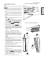
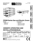
II. INSTALLATION KIT - see Figure 2-2
NOTE: One Installation Kit is required for each oven cavity.
Qty.
Part No.
1
1
35900-0148
Conveyor Rear Stop
Description
2
1
35000-1103
Conveyor End Stop
3
1
47008
4
1
1002040
3
2
4
ENGLISH
Item
Fig. 2-2 - Installation Kit
5
1
Owner's Operating & Installation Manual
Authorized Service Agency Listing
ADDITIONAL COMPONENTS FOR PS555G AND PS570G GAS OVENS:
5
1
33120-0053
Gas Pipe Nipple
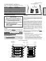
III. VENTILATION SYSTEM
CODES SUPERSEDE THE RECOMMENDATIONS SHOWN IN
THIS MANUAL.
IMPORTANT
The rate of air flow exhausted through the ventilation system
may vary depending on the oven configuration and hood design.
Consult the hood manufacturer or ventilation engineer for these
specifications.
Where national or local codes require the
installation of fire suppression equipment or
other supplementary equipment, DO NOT mount
the equipment directly to the oven.
To avoid a negative pressure condition in the kitchen area,
return air must be brought back to replenish the air that was
exhausted. A negative pressure in the kitchen can cause heatrelated problems to the oven components as if there were no
ventilation at all. The best method of supplying return air is
through the heating, ventilation and air conditioning (HVAC)
system. Through the HVAC system, the air can be temperaturecontrolled for summer and winter. Return air can also be
brought in directly from outside the building, but detrimental
effects can result from extreme seasonal hot and cold
temperatures from the outdoors.
MOUNTING SUCH EQUIPMENT ON THE OVEN MAY:
A.
VOID AGENCY CERTIFICATIONS
RESTRICT SERVICE ACCESS
LEAD TO INCREASED SERVICE EXPENSES
FOR THE OWNER
Requirements
CAUTION
Gas oven installations REQUIRE a mechanically driven
ventilation system with electrical exhaust air sensing control.
NOTE: Return air from the mechanically driven system must not
blow at the opening of the baking chamber. Poor oven baking
performance will result.
A mechanically driven ventilation system is STRONGLY
RECOMMENDED for electric oven installations.
PROPER VENTILATION OF THE
RESPONSIBILITY OF THE OWNER.
B.
OVEN
IS
THE
Recommendations
NOTE THAT THE HOOD DIMENSIONS SHOWN IN FIGURE 23 ARE RECOMMENDATIONS ONLY. LOCAL, NATIONAL, AND
INTERNATIONAL CODES MUST BE FOLLOWED WHEN
INSTALLING THE VENTILATION SYSTEM. ANY APPLICABLE
C.
Other ventilation concerns
Special locations, conditions, or problems may require the
services of a ventilation engineer or specialist.
Inadequate ventilation can inhibit oven performance.
It is recommended that the ventilation system and duct
work be checked at prevailing intervals as specified by the
hood manufacturer and/or HVAC engineer or specialist.
Fig. 2-3 - Ventilation System
458mm minimum
(Typical - both
ends of oven)
51mm
minimum
7
203mm
minimum
76mm
minimum
SECTION 2 - INSTALLATION
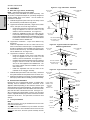
IV. ASSEMBLY
A.
Figure 2-4 - Legs and Casters - Standard
Base Pad, Legs, Casters, and Stacking
Front or Rear
of oven
ENGLISH
NOTE: Optional Stacking Lift Kit (P/N 30580)
The Stacking Lift Kit, P/N 30580, is available separately. This
Kit provides a complete lift adapter set, specifically designed for
stacking PS500 Series oven cavities. The Kit includes an
instructional videotape.
1.
1/2"
flat washer
Install the top panels in place on the top oven cavity. Follow
the instructions provided with the top panels.
2a. Legs/Casters Installation (Standard) - Single Ovens, Double
Ovens, and Triple Ovens with Leg Extensions
Install one leg extension to each corner of the base pad
using the supplied 1/2"-13x1-1/4" bolts, 1/2" flat
washers, and 1/2" lockwashers. See Figure 2-4.
Install one adjustable foot and one caster into the
holes on the bottom of the leg extension. The adjustable
foot should be installed into the OUTSIDE hole (closest
to the front or rear face of the oven). The caster should
be installed into the INSIDE hole.
1/2"
lock
washer
1/2"-13 x 1-1/4"
hex screw
Foot uses OUTSIDE
hole (closest to front
or rear of oven)
2b. Legs/Casters Installation - Triple Ovens Without Leg
Extensions
Install one adjustable foot and one caster into the 3/4"
holes on the bottom of the base pad. The adjustable foot
should be installed into the OUTSIDE hole (closest to the
front or rear face of the oven). The caster should be installed
into the INSIDE hole. See Figure 2-5.
Front or Rear
of oven
Install the base pad onto the lower oven cavity. Check that
the eyebolt welded onto the pad faces the rear of the oven.
4.
Stack the oven cavities. If necessary, refer to the instructional
videotape provided with the Stacking Lift Kit (P/N 30580).
B.
Restraint Cable Installation
Front or Rear
of oven
Left or Right Side
of oven
3/8"-16 x 1"
hex screw
Locking casters:
FRONT of oven
3/8" flat
washer
Non-locking
casters:
REAR of oven
Outrigger
After connecting the restraint cable, move the oven to its final
location. Adjust the bottom (hex) sections of the feet so that the
casters are off the floor. For quad ovens, lock the two front
casters.
Spacer
plate
1/2" flat
washer
Conveyor Installation
Locking
caster
shown
1/2" lock
washer
NOTE
Split belt conveyors can only be installed from the end of the
oven with the drive motor.
Single-belt conveyor assemblies may be inserted into either
end of the oven. If it is to be installed from the end of the oven
without the drive motor, the drive sprocket assembly must be
removed.
Caster
uses
INSIDE
hole
Figure 2-6 - Legs and Casters for Quad Oven
Because the oven is equipped with casters, a restraint cable
assembly must be installed to limit the movement of the
appliance without depending on the connector and the quick
disconnect device or its associated piping. One end of the cable
is anchored to the eyebolt on the rear surface of the oven's base
pad, while the other is anchored to the wall. See Figure 2-7.
C.
Left or Right Side
of oven
Foot uses OUTSIDE
hole (closest to front
or rear of oven)
Install the adjustable feet into the holes on the
underside of the outrigger assembly.
3.
Caster
uses
INSIDE
hole
Figure 2-5 - Legs and Casters for Triple Oven
Without Leg Extensions
2c. Legs/Casters Installation - Quad Ovens
Install one outrigger to each corner of the base pad
using the supplied 1/2"-13x1-1/4" bolts, 1/2" flat
washers, and 1/2" lockwashers. See Figure 2-6.
Install the spacer plates and casters onto the outriggers
using the 3/8"-16x1" screws, 3/8" flat washers, and
3/8"-16 hex nuts supplied in the Installation Kit. The
two locking casters should be installed on the front
side of the oven.
Left or Right Side
of oven
1/2"-13 x 1-1/4"
hex screw
8
3/8" flat
washer
Adjustable
foot
3/8"-16
hex lock nut
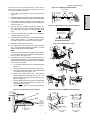
SECTION 2 - INSTALLATION
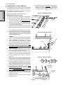
1.
Lift the conveyor and position it in the oven as shown in
Figure 2-9.
2.
Continue moving the conveyor into the oven until the frame
protrudes equally from each end of the oven (about 0.46m).
3.
Check that the retainers located on the underside of the
conveyor frame rest firmly against the lower end plugs, as
shown in Figure 2-9.
4.
When the conveyor is positioned properly, check for freedom of movement of the conveyor belt by pulling it for about
0.75-1.00m with your fingers. The conveyor must move
freely.
5.
If the drive sprocket was removed when installing the
conveyor, replace it at this time.
6.
Install the drive chain between the conveyor drive sprocket
and the motor sprocket. To install the chain, it will be
necessary to lift the drive end of the conveyor slightly.
7.
Install the conveyor drive motor cover.
8.
Check the tension of the conveyor belt as shown in Figure
2-10. The belt should lift between 75-100mm. DO NOT
OVERTIGHTEN THE CONVEYOR BELT.
Figure 2-7 - Installing the Restraint Cable
3/4 (19mm)
eyebolt
Restraint cable
assembly
Eyebolt in
base pad
Rear surface
of oven base
pad
Wall of
structure
Figure 2-8 - Removing the Conveyor Drive Sprocket
Loosen conveyor collar
set screw, then pull
sprocket straight out
Figure 2-9 - Inserting the Conveyor
1
NOTE:
If necessary, the belt tension can be adjusted by turning the
conveyor adjustment screws, located at the idler (right) end
of the conveyor. See Figure 2-10.
9.
If necessary, links can be added to or removed from the
conveyor belt to achieve the correct deflection of 75-100mm.
If links must be removed from the belt, it can be reattached
to the conveyor as follows:
a.
The conveyor belt links must be oriented as shown in
Figure 2-11.
b.
The smooth side of the conveyor belt must face UP.
c.
Connect the inside master links. Check that the links
are oriented as shown in Figure 2-11.
d.
Connect the outside master links. Note that the
outside master links have right and left sides. The
right-side master link has an open hook facing you, as
shown in Figure 2-11.
e.
f.
2
4
Check for freedom of movement of the conveyor belt by
pulling it for about 0.75-1.00m with your fingers. The
conveyor must move freely.
Retainer
3
Return to Step 8, above, to re-check the belt tension.
Figure 2-10 - Checking the conveyor tension
End plug
Figure 2-11 - Conveyor and Master Link Orientation
Direction
of travel
CORRECT
master link
position
Conveyor
tension
adjustment
screws (idler
end only)
Incorrect
master link
position
75-100mm vertical
deflection
9
Outside master link
orientation
Inside master link
orientation
ENGLISH
To remove the drive sprocket (if necessary), loosen the set
screw on the conveyor collar as shown in Figure 2-8. Then, pull
the sprocket assembly straight out.
SECTION 2 - INSTALLATION
V. FINAL ASSEMBLY
ENGLISH
1.
Install the crumb trays underneath the conveyor as shown
in Figure 2-12. First, place the inside edge of the tray onto
the retainer (shown in Figure 2-9). Then, swing the outside
edge of the tray up and into place.
2.
Press the conveyor end stop and rear stop down over the
edge of the conveyor frame. See Figure 1-1 (in Section 1,
Description).
Figure 2-12 - Crumb trays
Place inside
edge of tray on
retainer bracket
Swing outside
edge of tray
up and into
place
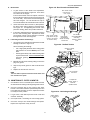
VI. ELECTRICAL SUPPLY
WARNING
Authorized supplier personnel normally accomplish
the connections for the ventilation system, electric
supply, and gas supply, as arranged by the customer.
Following these connections, the factory-authorized installer
can perform the initial startup of the oven.
Figure 2-13 - Utility Connection Locations for Gas Ovens
Electrical
Junction Box
One per oven cavity
NOTE: All aspects of the electrical supply connection must
comply with current IEC/CEE requirements and with all
applicable local, national, and international codes.
Check the oven serial plate before making any electric supply
connections. Electric supply connections must agree with data
on the oven serial plate. The location of the serial plate is shown
in Figure 1-1 (in Section 1, Description).
Equipotential
ground lug
A fused disconnect switch or a main circuit breaker (customer
furnished) MUST be installed in the electric supply line for each
oven cavity. The circuit breaker/disconnect must have 3mm
contact gaps breaking all poles of the supply. It is recommended
that this circuit breaker/disconnect have lockout/tagout capability.
Gas Inlet
One per Single, Double,
Triple, or Quad Oven
The supply conductors are to be 90°C-rated copper wiring.
Additional wiring information is shown on the wiring diagrams
in Section 5, Electrical Wiring Diagrams and inside the machinery compartment of the oven.
Figure 2-14 - Utility Connection Locations for Electric
Ovens
The oven requires a ground connection to the oven ground
screw located in the electrical junction box. (The box is shown
in Figures 2-13 and 2-14.) The ground connection must comply
with current IEC/CEE requirements and with all applicable
local, national, and international codes. If necessary, have the
electrician supply the ground wire. Do NOT use the wiring
conduit or other piping for ground connections!
A.
Additional Information - Gas Ovens
All electric supply connections are made via the electrical
junction box on the rear of the oven, shown in Figure 2-13. The
power lines then connect to the oven circuits through safety
switches located inside the machinery compartment and each
blower motor compartment. These switches interrupt electric
power to the oven when the Machinery Compartment Access
Panel is opened, OR when either of the blower or rear shrouds
is removed.
B.
Equipotential
ground lug
C.
Additional Information - Electric Ovens
51mm cutout for
electrical supply
Connection
A 51mm dia. cutout in the back wall of the machinery compartment
provides access to the electrical supply connections. See
Figure 2-14. The actual wiring connections are made at the
terminal block located inside the side compartment of the oven.
Refer to the wiring diagram inside the machinery compartment,
or in Section 5 of this Manual, to determine the correct
connections for the electrical supply lines. Connect the supply
as indicated on the wiring diagram.
Using flexible cables for the electric power supply conductors
requires a 51mm strain-relief fitting (not furnished with the
oven) to enable safe access to the terminal block.
If required by national or local codes, connect an equipotential
ground wire to the lug next to the
symbol (shown in Figures
2-13 and 2-14). The equipotential ground connection must
meet all applicable national and local code requirements.
10
SECTION 2 - INSTALLATION
VII. GAS SUPPLY
CAUTION
A.
1. The oven and its individual shutoff valve must be disconnected from the gas supply piping system during any
pressure testing of that system at test pressure in excess
of 3.45 kPa.
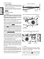
WARNING: To prevent damage to the control valve regulator during initial turn- on of gas, it is very important to open
the manual shutoff valve very slowly.
2. The oven must be isolated from the gas supply piping
system by closing its individual manual shutoff valve during
any pressure testing of the gas supply piping system at test
pressure equal to or less than 3.45 kPa.
After the initial gas turn-on, the manual shutoff valve must
remain open except during pressure testing as outlined in
the above steps or when necessary during service maintenance.
Connection
the ovens serial plate and in Table 1-5, Gas Orifice and
Pressure Specifications (in Section 1, Description).
WARNING
Some procedures in this section may require conversions, readjustments, or service on the oven's gas system.
Before performing these procedures, check that the main
gas supply valve and the circuit breaker/fused disconnect
are in the OFF ("O") position. After completing these procedures, perform a gas leak test before operating the oven.
Check the serial plate to determine the type of gas to be used
with the oven. Check that the gas type indicated matches the
local supply at the installation. If the gas type on the serial plate
does NOT match the local supply, directions for converting the
oven for use with other gases are described in Part B, Preparation
for Use with Various Gases, in this section.
CAUTION
The terms of the oven's warranty require all start-ups, conversions and service work to be performed by a Middleby Marshall
Authorized Service Agent. The installation, start-up and changes
required when changing from one gas type to another can be
performed ONLY by a certified professional.
One 90° elbow equals a 2.13m length of pipe. The recommended
pipe sizes are larger than usually required to eliminate any
operation problems. It is much less expensive to make the
initial installment large enough to do the job rather than redoing
the job later.
NOTE: The gas supply connection should be according to
applicable ISO 228-1 or ISO 7-1 recommendations. All aspects
of the gas supply connection must comply with current IEC/CEE
requirements and with all applicable local, national, and international codes.
Refer to the instructions in the gas hose package (included in
the Installation Kit) before connecting the gas line. One gas line
connection method is shown in Figure 2-15; however,
compliance with the applicable standards and regulations is
mandatory.
Check the ovens gas supply requirements before making the
gas utility connection. Gas supply requirements are listed on
Figure 2-15 - Flexible Gas Hose Installation
To Gas
Supply Pipe
Full-Flow
Gas
Shutoff
Valve
90°
Elbow
90°
Elbow
Flexible
Gas Hose
Union OR quickdisconnect device
11
ENGLISH
3. If incoming pressure is over 50mbar, a separate regulator MUST be installed in the line BEFORE the individual
shutoff valve for the oven.
DURING PRESSURE TESTING NOTE ONE OF THE FOLLOWING:
SECTION 2 - INSTALLATION
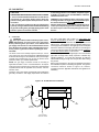
Figure 2-16 - Gas Burner
and Piping Assembly
Type 1 Gas Control Valve
Cap for
top oven
cavity
Type 2 Gas Control Valve
Manifold pressure
adjustment (under
cap screw)
Supply (inlet)
pressure tap
ENGLISH
Manual
shutoff
valve
Governor
disabled for
liquid
propane
operation
Manifold pressure
adjustment
1/2" union
Gas Control
Valve
(see inset)
Gas line for
other oven
cavities
Orifice (manifold)
pressure tap
Governor
enabled for
natural gas
operation
Modulating
gas valve
Burner
Blower
Gas Burner
Nipple, 1-1/4"
dia. X 3"
(76mm) L, NPT
Elbow, 90°,
1-1/4 dia.
B.
Gas
pressure
switch
Pilot
pressure
tap
Preparation for Use with Various Gases
Before proceeding to set up the oven for a specific gas, check
that the main gas supply valve and the circuit breaker/fused
disconnect are in the OFF ("O") position.
The main and pilot orifices must match the sizes shown in Table
1-5. If necessary, replace the orifices. Refer to Part C, Replacing
the Gas Orifices.
The orifice (manifold) pressure should be adjusted to the value
shown in Table 1-5 (in the Description section) for the specific
gas type and location.
1.
2.
For Use with Natural Gas
The actual heat input to the oven must match the rated heat
input. The input to the burner can be determined using the
orifice (manifold) pressure data or by the volume supplied
using the gas meter. Both of these procedures are
described in Part E, Checking the Heat Input.
If the measured input does not correspond with the rated
input (shown in Table 1-5 in the Description section of this
Manual), check first that the correct orifices are installed. If
the orifices are correct, check and correct the supply and
orifice pressures to obtain the correct input based on the
gas meter reading.
For Use with Liquid Propane (LP) Gas
When using liquid gas with an oven equipped with a Type
2 gas control valve (see Figure 2-16), the converter in the
multifunction gas valve must be removed, and then replaced
INVERTED from its former position. Inverting the converter
will disable the governor. This step is only required if the
supply pressure is below 50mbar.
C.
Replacing the Gas Orifices (if so required)
1.
Replacing the Main Orifice
a. Check that the main gas supply valve and the circuit
breaker/fused disconnect are in the OFF ("O") position.
b. Open the 1/2" union in the gas supply line. The union
is located between the oven's manual shutoff valve
12
and the multifunction gas valve. See Figure 2-16.
c.
d.
e.
f.
Refer to Figure 2-17. Unscrew the four hex screws that
hold the venturi mounting plate to the front of the
burner. Remove the gas train/venturi assembly from
the oven.
Remove the two 1/2" nuts that secure the gas train to
the venturi mounting plate.
Remove the main orifice using an 11/16" wrench.
Install the new orifice by following the above procedure
in reverse order.
Figure 2-17 - Replacing the Main and Pilot Orifices
Ignition
sensor
wire
Venturi
assembly
Pilot
orifice
Venturi
mounting
plate
Compression
nut
Pilot tube
Main orifice
holder (attached
to gas train)
Main
orifice
1/2" hex nuts
SECTION 2 - INSTALLATION
Replacing the Pilot Orifice
1.
NOTE: All natural gases use the same size pilot orifice
(0.635mm), as do all liquid propane (LP) gases (0.381mm).
Because of this, it is not normally necessary to replace the
pilot orifice unless converting the oven from natural to
propane, or from propane to natural, operation.
a.
b.
c.
d.
e.
f.
g.
Follow Steps a-d in Replacing the Main Orifice, above.
Refer to Figure 2-17. Unscrew the pilot tube
compression nut and slide it out of the way. Pull the
tube from the fitting to expose the pilot orifice.
Remove the pilot orifice.
Slip the new pilot orifice into the pilot tube.
Push the pilot tube back into place until it bottoms, and
hold it in place. Slide the compression nut back into
place and engage the threads. Tighten the nut to a
snug fit with your fingers.
Gently tighten the nut one complete turn with a wrench.
DO NOT OVERTIGHTEN THE COMPRESSION NUT.
Replace the gas train and venturi by following Steps ad in Replacing the Main Orifice, above, in reverse order.
Orifice (Manifold) Pressure Method
a.
Check that the main gas supply valve and the circuit
breaker/fused disconnect are in the OFF ("O") position.
b.
Attach a manometer to record the regulated (manifold)
pressure. For a Type 1 gas control valve, you will need
to remove the cap from the open end of the gas line tee
as the line enters the burner. For a Type 2 valve, you
can connect the manometer to this location, or to the
stud on the valve, shown in Figure 2-16 (underneath
the cap screw).
c.
For a Type 2 gas control valve, remove the cap screw
from the pressure adjustment screw (governor). The
Type 1 valve does not have a cap screw.
d.
Depress the two machinery compartment safety
switches to allow the oven to operate.
e.
Open the main gas supply valve. Switch the circuit
breaker/fused disconnect to the ON ("I") position.
f.
Start the oven according the directions in the Operation
section of this Manual. Adjust the temperature controller
to the maximum setting (288°C).
g.
Adjust the pressure adjustment screw as necessary
to match the correct pressure for the oven's specific
gas type. Refer to Table 1-5 in the Description section
of this Manual. Turning the adjustment screw clockwise
increases the flow, while turning it counterclockwise
reduces the flow.
h.
Switch the oven off. Close the main gas supply valve,
and switch the circuit breaker/fused disconnect to the
OFF ("O") position. Remove the manometer, and
replace all cap screws and gas line caps.
WARNING
After completing these procedures, perform a gas
leak test before operating the oven.
D.
Checking the Gas Supply (Inlet) Pressure
1.
Attach a manometer to record the supply (inlet) pressure.
For a Type 1 gas control valve (see Figure 2-16), you will
need to check the supply pressure at the gas connection
to the oven. For a Type 2 gas control valve, remove the
supply (inlet) pressure cap screw and attach a manometer
to the stud.
2.
Depress the two machinery compartment safety switches
to allow the oven to operate.
3.
Open the main gas supply valve. Switch the circuit breaker/
fused disconnect to the ON ("I") position.
4.
Start the oven according the directions in the Operation
section of this Manual. Adjust the temperature controller to
the maximum setting (288°C).
5.
Measure the supply (inlet) pressure.
6.
Switch the oven off. Close the main gas supply valve, and
switch the circuit breaker/fused disconnect to the OFF ("O")
position. Remove the manometer. For a Type 2 gas control
valve, replace the cap screw.
7.
Compare the measured supply (inlet) pressure to the
nominal pressures shown in Table 1-5 (in the Description
section of this Manual).
2.
Volumetric Method
a.
Determine the time of 0.1m3 (100 liters) of gas usage
as follows.
Consumption (m3/hr.) =
Time (in minutes) of
=
0.1m3 of gas usage
NB (Rated input in kW)
HuB (Heat [Calorific] value
of gas in kW/m3)
6
Consumption
b.
Check that the main gas supply valve and the circuit
breaker/fused disconnect are in the OFF ("O") position.
c.
For a Type 2 gas control valve, remove the cap screw
from the pressure adjustment screw (governor). The
Type 1 valve does not have a cap screw.
d.
Depress the two machinery compartment safety
switches to allow the oven to operate.
e.
If the supply pressure is lower or higher than the nominal
pressure, the reason should be investigated and the gas
supplier contacted.
Open the main gas supply valve. Switch the circuit
breaker/fused disconnect to the ON ("I") position.
f.
For natural gas ovens, if the measured supply pressure is lower
than 17mbar, or higher than 25mbar, contact the gas supplier.
DO NOT OPERATE THE OVEN or adjust the oven controls.
Start the oven according the directions in the Operation
section of this Manual. Adjust the temperature controller
to the maximum setting (288°C).
g.
Adjust the pressure adjustment screw as necessary
to match the calculated volume using the time (in
minutes) of 0.1m 3 of gas usage. Turning the
adjustment screw clockwise increases the flow, while
turning it counterclockwise reduces the flow.
h.
Record the reading obtained from the gas meter and
calculate the obtained gas flow. Compare this value
to the information in Table 1-4 in the Description
section of this Manual.
i.
Switch the oven off. Close the main gas supply valve,
and switch the circuit breaker/fused disconnect to the
OFF ("O") position. For a Type 2 gas valve, replace the
cap screw.
E.
Adjusting the Orifice (Manifold) Pressure and Heat Input
To use the orifice pressure method, you must know the specific
gas type and quality used. If using the orifice pressure method,
you should double-check the input using the volumetric method.
To use the volumetric method, you must know the heat value
(HuB) of the gas used. This information is available from your
gas supplier.
During these measurements, do not operate any other
13
appliances that use the same gas meter as the oven.
ENGLISH
2.
SECTION 3 - OPERATION
I.
LOCATION AND DESCRIPTION OF CONTROLS
Fig. 3-1 - Control Panel
ENGLISH
F.
D.
Digital Temperature
"RESET"
(
) controller
) switch
(
GAS OVENS
ONLY
E.
Conveyor Speed
(
(
A.
C.
"BLOWER"
"CONVEYOR"
B.
) switch
(
) controller(s)
) switch
"HEAT"
(
A.
"BLOWER" Switch: Turns the blowers and
cooling fans on and off. The HEAT Switch has
no effect unless the BLOWER Switch is in the
ON position.
B.
"HEAT" Switch: Allows the burner or heating
elements, as appropriate for the oven model, to
activate. Activation is determined by the settings on the Digital Temperature Controller.
C.
D.
) switch
"CONVEYOR" Switch: Turns the conveyor drive
motor on and off.
E.
Conveyor Speed Controller: Adjusts and displays the bake time. Single-belt ovens have one
controller. Split belt ovens have one controller
for each conveyor belt, labeled "FRONT" and
"BACK."
F.
Digital Temperature Controller: Continuously
monitors the oven temperature. Settings on the
Digital Temperture Controller control the activation of the burner or heating elements.
NOT SHOWN:
G.
"RESET" Switch: Gas ovens only. Illuminates
if the gas burner does not light. The switch can
be pressed repeatedly to attempt to light the
burner. If the burner does not light within 15
) switch is locked out.
minutes, the "RESET" (
14
Machinery Compartment Access Panel Safety Switches:
Disconnect electrical power to the controls and the blowers
when the machinery compartment access panel is opened.
The panel should only be opened by authorized service
personnel.
7.
II. NORMAL OPERATION - STEP-BY-STEP
A.
DAILY STARTUP PROCEDURE
1.
Check that the circuit breaker/fused disconnect is in the on
position. Check that the window is closed.
2.
Turn the "BLOWER" ( )
switch to the ON ("I")
position.
3.
4.
5.
6.
NOTE: If the burner does not light within 15 minutes, the
oven enters a safety lockout mode that disables the "RESET" ( ) switch. If this occurs, turn the "HEAT" ( ),
) switches to the
"BLOWER" ( ), and "CONVEYOR" (
"OFF" ("O") position. Wait for AT LEAST FIVE MINUTES.
Then, repeat the Daily Startup procedure.
Turn the "CONVEYOR"
) switch to the ON
(
("I") position.
If necessary, adjust the
conveyor speed setting
or
by pressing the
pushbuttons on the conveyor speed controller to
change the displayed
bake time.
Adjust the temperature
controller to a desired set
temperature, if necessary.
Press the Set Point
and Unlock keys at
the same time. Wait
for the "SET PT" light
to turn on.
Press the Up Arrow
and Down Arrow
Keys as necessary
to adjust the setpoint.
(Gas ovens only) If the "RESET" ( ) switch illuminates, the gas burner did
not light. Press the "RESET" ( ) switch (repeatedly if necessary) to attempt to light the burner.
8.
Wait for the oven to heat to the setpoint temperature. Higher
setpoint temperatures will require a longer wait. The oven
can reach a temperature of 232°C in approximately 5
minutes.
9.
(Optional) Press the Temperature ( ) key to show
the Actual Temperature
in the display, and wait
for the "ACTUAL TEMP"
light to turn on. This allows you to monitor the
oven temperature as it
rises to the setpoint.
or
wait
for
10. Allow the oven to preheat for 10 minutes after it has reached
the set point temperature.
+
wait
for
B.
DAILY SHUTDOWN PROCEDURE
1.
Turn the "HEAT" ( ) and
"BLOWER" ( ) switches to the "OFF" ("O")
position. Note that the
blowers will remain in operation until the oven has
cooled to below 93°C.
2.
Make certain that there
are no products left on
the conveyor inside the
oven. Turn the "CON) switch to
VEYOR" (
the "OFF" ("O") position.
3.
Open the window to allow the oven to cool faster.
4.
After the oven has cooled and the blowers have turned off,
switch the circuit breaker/fused disconnect to the off position.
or
Turn the "HEAT" ( )
switch to the "ON" ("I")
position, and wait for the
"HEAT ON" light to turn
on.
+
CAUTION
In case of power failure, turn all switches to the OFF ("O")
position, open the oven window, and remove the product.
After the power has been restored, perform the normal
startup procedure.
wait
for
On gas ovens, the burner will not operate and gas will not
flow through the burner without electric power. No
attempt should be made to operate the oven during a
power failure.
15
ENGLISH
SECTION 3 - OPERATION
SECTION 3 - OPERATION
III. QUICK REFERENCE: DIGITAL TEMPERATURE CONTROLLER
ENGLISH
"SP LOCK" Light
Lights when the set
point is locked out
from changes. This
setting can only be
changed by service
personnel.
Display
Shows the Set Point or
the Actual Temperature in degrees Fahrenheit (F) or Celsius
(C).
"HEAT ON" Light
Lights when the
burner or heating elements, as appropriate
for the oven model,
are in operation.
"SET PT" (setpoint)
Light
Lights when the set
point is shown in the
display.
OVERTEMP Light
Lights when the oven
temperature is greater
than 343°C. Refer to
Quick
Reference:
Troubleshooting in
this section.
"ACTUAL TEMP"
Light
Lights when the
Actual Temperature is shown in
the display.
Service Key
For use by service personnel
only.
Temperature Key
Press this key once to
view the Actual Temperature in the Display.
Unlock Key
Press this key together
with the Set Point Key
to allow the Set Point
to
be
changed.
Changes can only be
made for 60 seconds.
Up Arrow and Down Arrow
Keys
Press these keys to adjust
the Set Point up or down. If
the Set Point will not
change, refer to Set Point
Key and Unlock Key in this
section.
16
Set Point Key
Press this key together
with the Unlock Key to
allow the Set Point to
be changed.
Changes can only be
made for 60 seconds.
SECTION 3 - OPERATION
SYMPTOM
TROUBLESHOOTING
PROBLEM
SOLUTION
The oven temperature exceeded 343°C, and the
burner or heating elements
were automatically shut
down.
Follow the procedures under Daily Shutdown Procedures in
this section to shut down the oven. Contact your Middleby
Marshall Authorized Service Agent to determine and correct the
cause of the condition to prevent damage to the oven.
Oven will not
turn on at all
Electrical power may not be
reaching the oven, or the
controls may be set incorrectly.
Check that the circuit breaker/fused disconnect is turned on.
Check that the "BLOWER" ( ) Switch is in the ON ("I")
position. The burner cannot engage until the blowers are in
operation.
"RESET" ( ) switch is
illuminated, oven will not
heat
(gas ovens only)
The gas burner did not light
within 90 seconds of turning the "HEAT" ( ) Switch
to the ON ("I") position.
Press the "RESET" ( ) switch (repeatedly if necessary) to
attempt to light the burner.
If the burner does not light within 15 minutes, the oven will enter
a safety lockout mode that disables the "RESET" ( ) switch.
If this occurs, turn the "HEAT" ( ), "BLOWER" ( ), and
)switches to the "OFF" ("O") position. Wait
"CONVEYOR" (
for AT LEAST FIVE MINUTES before restarting the oven. Then,
repeat the Daily Startup procedure.
The oven did not reach
93°C within 15 minutes of
startup, and the oven has
stopped heating.
Turn the "HEAT" ( ), "BLOWER" ( ), and "CONVEYOR"
)switches to the "OFF" ("O") position.
(
Wait for AT LEAST FIVE MINUTES before restarting the oven.
Repeat the Daily Startup procedure.
Controls may be set incorrectly.
Check that the Set Point is correctly set.
Check that both the "BLOWER" (
are in the ON ("I") position.
If the oven still will not heat,turn the "HEAT" ( ), "BLOWER"
), and "CONVEYOR" (
)switches to the "OFF" ("O")
position.
light is lit, food product is
undercooked
appears in display,
oven is not heating
Oven will not heat
) and "HEAT" (
) Switches
(
Wait for AT LEAST FIVE MINUTES before restarting the oven.
Repeat the Daily Startup procedure. Check that the Set Point
is above 93°C.
Oven is operating, but
little or no air is blowing
from air fingers
Air fingers may have been
reassembled incorrectly
after cleaning.
Turn the oven off, and allow it to cool. Disconnect electrical
power to the oven.
Refer to Section 4, Maintenance, for instructions on reassembling the air fingers.
Conveyor moves with a
jerky motion, or will not
move at all
Conveyor may be jammed
on an object in the oven, or
conveyor belt or drive chain
tension may be incorrect.
Turn the oven off, and allow it to cool. Disconnect electrical
power to the oven.
Check if the conveyor is blocked by an object inside the oven.
Refer to Section 4, Maintenance, for instructions on checking
the conveyor and drive chain tension.
Controls may be set incorrectly.
Check that the set temperature and bake time settings are
correct.
Food products are
overcooked or
undercooked.
IF THESE STEPS FAIL TO RESOLVE THE PROBLEM, CONTACT YOUR LOCAL MIDDLEBY MARSHALL
AUTHORIZED SERVICE AGENT. A SERVICE AGENCY DIRECTORY IS SUPPLIED WITH YOUR OVEN.
17
ENGLISH
IV. QUICK REFERENCE:
SECTION 4 - MAINTENANCE
WARNING
Before ANY cleaning or servicing of the oven, perform the following procedure:
ENGLISH
1.
2.
3.
Switch off the oven and allow it to cool. Do NOT service the oven while it is warm.
Turn off the electric supply circuit breaker(s) and disconnect the electric supply to the oven.
If it is necessary to move a gas oven for cleaning or servicing, disconnect the gas supply connection before moving the oven.
When all cleaning and servicing is complete:
1. If the oven was moved for servicing, return the oven to its
original location. Adjust the legs so that they are seated
properly on the floor.
2. For gas ovens, reconnect the gas supply.
3. Reconnect the electrical supply.
4.
5.
6.
For gas ovens, turn on the full-flow gas safety valve. Test
the gas line connections for leaks using approved leak
test substances or thick soap suds.
Turn on the electric supply circuit breaker(s).
Perform the normal startup procedure.
WARNING
Possibility of injury from moving parts and electrical shock exists in this oven. Switch off and lockout/tagout the electric supply
BEFORE beginning to disassemble, clean, or service any oven. Never disassemble or clean an oven with the BLOWER ( )
switch or any other circuit of the oven switched on.
CAUTION
NEVER use a water hose, water jet, or pressurized steam-cleaning equipment when cleaning this oven. DO NOT use
excessive amounts of water, to avoid saturating the oven insulation. DO NOT use a caustic oven cleaner, which can damage
the aluminized bake chamber surfaces.
NOTE
ANY replacement parts that require access to the interior of the oven may ONLY be replaced by a Middleby Marshall Authorized
Service Agent. It is also strongly recommended that the 3-Month Maintenance and 6-Month Maintenance procedures in this
section be performed ONLY by a Middleby Marshall Authorized Service Agent.
I. MAINTENANCE - DAILY
A.
Check that the oven is cool and the power is disconnected,
as described in the warning at the beginning of this Section.
B.
Clean the outside of the oven with a soft cloth and mild
detergent.
C.
Clean the front cooling fans, as follows:
Snap off the protective grille, and wipe it clean with a cloth.
See Figure 4-1.
Remove the foam filter and inspect it. If it is dusty, shake
it briskly. If dirt or grease is present on the filter, wash it
in warm, soapy water. Rinse the filter, squeeze it to
remove as much of the water as possible, and then set
it aside to dry thoroughly before reinstallation.
Once the filter is dry, reinstall the filter and grille.
D.
Clean the motor shroud and rear grills using a stiff nylon
brush. Refer to Figure 4-2 for the locations of the grills.
E.
Check that ALL cooling fans are operating properly.
CAUTION
If a cooling fan is not operating correctly, it must be replaced
IMMEDIATELY. Operating the oven without adequate
cooling can damage the oven's internal components.
F.
Clean the conveyor belts with a stiff nylon brush. This is
more easily accomplished by allowing the conveyor to run
while you stand at the exit end of the conveyor. Then, brush
the crumbs off the conveyor as it moves.
G.
Remove and clean the crumb trays. When reinstalling the
trays, refer to Figure 2-12 (in Section 2, Installation).
H.
Figure 4-1 - Front Cooling Fans
Foam filter
Protective grill
Figure 4-2 - Rear Grills and Motor Shroud Grill
Grill on top of
conveyor motor
shroud
Grills on top
and bottom
of rear
shrouds (4)
Clean the window in place.
18
Grills on inside
face of rear
shrouds (2 - gas
ovens only)
Grills on rear of
rear shrouds (2)
Grills on end
shrouds (4)
SECTION 4 - MAINTENANCE
II. MAINTENANCE - MONTHLY
Figure 4-3 - Removing Air Fingers and Plates
NOTE
A.
Check that the oven is cool and the power is disconnected,
as described in the warning at the beginning of this Section.
B.
Remove the crumb trays and drive motor shroud from the
oven.
C.
Lift the drive end of the conveyor slightly, and push it forward
into the oven. This removes the tension from the drive
chain. Then, remove the drive chain from the conveyor
sprocket.
D.
Slide the conveyor out of the oven, folding it as it is removed.
ENGLISH
When removing the conveyor, refer to Figure 2-9 (in Section 2,
Installation).
NOTE
Split belt conveyors can only be removed from the end of
the oven with the drive motor.
Single-belt conveyor assemblies may be removed from
either end of the oven. If it is to be removed from the end
of the oven without the drive motor, remove the drive motor
sprocket as described in the Conveyor Installation instructions (in Section 2, Installation).
E.
Remove the end plugs from the oven. The end plugs are
shown in Figure 1-1 (in Section 1, Description).
F.
Slide the air fingers and blank plates out of the oven, as
shown in Figure 4-3. AS EACH FINGER OR PLATE IS
REMOVED, WRITE A "LOCATION CODE" ON IT WITH A
MARKER to make sure that it can be reinstalled correctly.
Figure 4-4 - Disassembling the Air Fingers
Manifold
Example of markings:
G.
Inner plate
(Top Row)
T1
T2
T3
T4
T5
T6
(Bottom Row)
B1
B2
B3
B4
B5
B6
Outer Plate
Disassemble the air fingers as shown in Figure 4-4. AS
EACH FINGER IS DISASSEMBLED, WRITE THE "LOCATION CODE" FOR THE FINGER ON ALL THREE OF ITS
PIECES. This will help you in correctly reassembling the
air fingers.
2
3
Pull outer plate
straight up
and off
Swing ends of inner plate and
manifold apart
CAUTION
Incorrect reassembly of the air fingers will change the
baking properties of the oven.
H.
Clean the air finger components and the interior of the
baking chamber using a vacuum cleaner and a damp cloth.
Refer to the boxed warnings at the beginning of this Section
for cleaning precautions.
I.
Reassemble the air fingers. Then, replace them in the
oven, using the "location code" as a guide.
J.
Replace the end plugs on the oven.
K.
Reassemble the conveyor into the oven. If the drive sprocket
was removed when installing the conveyor, replace it at this
time.
L.
Reattach the drive chain.
M.
Check the tension of the conveyor belt as shown in Figure
2-10 (in Section 2, Installation). The belt should lift between
75-100mm. DO NOT OVERTIGHTEN THE CONVEYOR
BELT. If necessary, the belt tension can be adjusted by
turning the conveyor adjustment screws, located at the
idler (right) end of the conveyor.
N.
4
Pull inner plate
upwards, and
then away from
manifold
1
Replace the crumb trays and drive motor shroud.
Step on lip of manifold
19
SECTION 4 - MAINTENANCE
III. MAINTENANCE - EVERY 3 MONTHS
ENGLISH
A.
Check that the oven is cool and the power is disconnected,
as described in the warning at the beginning of this Section.
B.
Vacuum both of the blower motors, and their surrounding
compartments, using a shop vacuum.
16 Check the tension of the conveyor belt as shown in
Figure 2-10 (in Section 2, Installation). The belt should
lift between 75-100mm. If necessary, adjust the belt
tension by turning the conveyor adjustment screws.
Figure 4-5 - Split Belt Idler Shaft
C. Tighten all electrical control terminal screws.
D. Split Belt Disassembly and Cleaning
For split belt ovens ONLY, disassemble, clean and lubricate the conveyor shaft components as described below.
1.
Remove the motor shroud, conveyor extensions, and
conveyor as described in Part II, Monthly Maintenance.
2.
Remove the master links from each conveyor belt.
Then, roll the belts up along the length of the conveyor
to remove them from the frame.
3.
Remove the two conveyor adjustment screws from the
idler end of the conveyor frame, as shown in Figure 45.
4.
Remove the idler shaft assembly from the conveyor.
5.
Pull apart the two sections of the idler shaft. Clean the
shafts thoroughly using a rag. Then, lubricate both the
extended shaft and the interior of the hollow shaft using
a light food-grade lubricant.
Conveyor
adjustment
screw
Figure 4-6 - Split Belt Drive Shaft
CAUTION
DO NOT lubricate the shafts using WD40 or a similar
product. This can cause the shafts to wear rapidly.
6.
Before reassembling the shafts into the conveyor
frame, check that they are oriented properly. Remember that unequal-width split belt ovens should ALWAYS have the narrower belt at the front of the oven.
7.
Reassemble the idler shaft into the conveyor. Make
sure that the bronze washer is in place between the two
sections of the shaft. See Figure 4-7.
8.
Replace the conveyor adjustment screws as shown in
Figure 4-5. To allow the conveyor belt to be reinstalled
later, do not tighten the screws at this time.
9.
Loosen the set screw on both of the conveyor drive
sprockets. Then, remove the sprockets from the shaft.
Locking collar
10. Loosen the locking collar set screw, as shown in
Figure 4-6.
Figure 4-7 - Washer and Spacer
11. Push the drive shaft to the right, then lift it free of the
conveyor frame. Then, disassemble and lubricate the
two sections of the drive shaft as described in Step 5.
12. Before reassembling the shafts into the conveyor
frame, check that they are oriented properly. Remember that unequal-width split belt ovens should ALWAYS have the narrower belt at the front of the oven.
Bronze washer on
BOTH idler and
drive shafts
13. Reassemble the drive shaft into the conveyor. Check
that the nylon spacer is in place, as shown in Figure 47. Also, check that the bronze washer is in place
between the two sections of the shaft.
Nylon spacer
on drive shaft
ONLY
14. Replace the drive sprockets. Reassemble the belts
and master links onto the conveyor, and replace the
conveyor in the oven.
15. Reassemble the motor shroud and conveyor extensions onto the oven.
20
SECTION 4 - MAINTENANCE
E.
Figure 4-8 - Rear Shrouds and Guard Plates
Blower Belts
1.
To gain access to each blower belt compartment,
remove the screws shown in Figure 4-8. Then, lift the
rear shroud off its hangers.
End shroud screws
(3 per shroud - 1
rear, 2 front)
F.
2.
Check each blower belt for at least 1" (25mm) deflection at the center, and for cracking or excessive wear.
See Figure 4-9. Overtightening the belt will cause
premature bearing failure and possible vibrations.
3.
If necessary, adjust the tension of the belt by loosening
the four motor mounting bolts. Reposition the motor
as necessary until the correct deflection is reached,
then tighten the motor mounting bolts.
ENGLISH
If access to the blower motors is required, remove the
three mounting screws (two on the front of each shroud,
one on the rear). Then, lift the end shroud straight up
and off its hangers. The end shrouds can only be
removed AFTER the rear shrouds have been removed.
Rear shroud screws
(4 per shroud for gas
ovens, 5 per shroud
for electric ovens)
Lubricating the Blower Fan Bearings
1.
Use a grease gun to lubricate the main blower fan shaft
bearings, as shown in Figure 4-10.
Use a high-quality NLGI #2, lithium soap grease
with petroleum oil, such as Middleby P/N 171100015.
Add the grease slowly until a small bead of grease
is present at the seals. AVOID OVERGREASING.
Excessive greasing may cause harm to the
bearing.
2.
Manually turn the blower shaft by pulling on the belt to
purge the grease.
3.
Wipe off any excess grease on and around the bearings.
4.
Replace the shrouds onto the oven.
End shroud remove SECOND (if
necessary).
Access to blower
motor
Figure 4-9 - Fan Belt Tension
When lubricating the bearings:
Rear shroud remove FIRST.
Access to bearing
and fan belt
At least 1" (25mm)
deflection
Fan not shown see above
NOTE
The oven will not operate unless ALL of the motor and
rear shrouds are in place.
IV. MAINTENANCE - EVERY 6 MONTHS
A.
Check that the oven is cool and the power is disconnected,
as described in the warning at the beginning of this Section.
To adjust belt
tension, loosen 4
bolts and
reposition motor
B.
Check for excessive wear on the conveyor drive motor
brushes. The brushes should be replaced if they have worn
to less than 6mm in length. Be sure to replace the brushes
in exactly the same position.
Figure 4-10 - Lubricating the Bearings
C.
For gas ovens, clean and inspect the burner nozzle and
electrode assembly.
D.
Check (and clean, if necessary) the oven venting system.
E.
Check the conveyor drive shaft bushings and spacers.
Replace the components if they are worn.
Grease fittings
(1 per bearing, 4
total)
21
SECTION 4 - MAINTENANCE
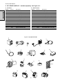
V. KEY SPARE PARTS KIT - Available separately. See Figure 4-11.
A.
Gas Ovens
Item Qty.
Part No.
ENGLISH
1
1
36939
2
1
3
4
B.
Description
Electric Ovens
Item Qty.
Part No.
Description
Kit, Digital Temperature Controller
1
1
36939
Kit, Digital Temperature Controller
27384-0008
Motor, Conveyor Drive
2
1
27384-0008
Motor, Conveyor Drive
2
22450-0052
Brushes, Drive Motor
3
2
22450-0052
Brushes, Drive Motor
1
37337
Kit, Conveyor Speed Controller
4
1
37337
5
1
27170-0263
Assembly, Pickup, Conveyor Drive
5
1
27170-0263
6
1
33984
Kit, Thermocouple
6
1
33984
Kit, Thermocouple
7
1
97525
Fan, Cooling
7
1
97525
Fan, Cooling
8
1
27381-0069
Motor, Blower, 1 HP
8
1
27381-0069
9
1
39530
Air Switch
14
1
33983
10
1
35825
Kit, Ignition Module
15
1
44526
11
1
38811
Assembly, Burner Blower/Motor
16
1
28041-0008
Contactor
12
1
41647
Valve, Modulating Gas, 1/2"
17
1
44549
Contactor
13
1
31651
Amplifier, Modulating Valve
18
1
35018
Circuit breaker block, 3-pole, 50A
14
1
33983
High limit control module, 240V
19
1
44568
Controller
Kit, Conveyor Speed Controller
Assembly, Pickup, Conveyor Drive
Motor, Blower, 1 HP
High limit control module, 240V
Heating element, 380V
Fig. 4-11 - Key Spare Parts Kit
1
5
4
3
2
7
6
10
9
8
11
12
13
14
15
16
17
18
22
19
RFI
FILTER
CIRCUIT
BREAKERS
23
BLOWER
SWITCH
TEMP CONTROL
CONTACT
CONVEYOR
SWITCH
DOOR
SWITCH
TEMP CONTROL
CONTACT
COOLING FAN
COOLING FAN
CONTACTOR
DOOR SWITCH
DOOR SWITCH
DOOR SWITCH
RESET
IMPORTANT
TRANSFORMER
230V PRI.
120V SEC.
200 VA
SECOND CONVEYOR
CONTROL FOR USE IN SPLIT
BELT APPLICATIONS ONLY
AIR SWITCH
LEFT REAR
AIR SWITCH
RIGHT REAR
TRANSFORMER
240V PRI.
24V SEC.
25 VA
HEAT
SWITCH
IGNITION
MODULE
SIGNAL
AMPLIFIER
ENGLISH
GAS
PRESSURE
SWITCH
BURNER BLOWER AIR
PRESSURE SWITCH
GAS
CONTROL
VALVE
TEMP
CONTROL
CONTACT
MODULATING
GAS VALVE
IGNITION RESET LAMP
An electrical wiring diagram for the oven is also located inside the machinery compartment.
HIGH LIMIT
THERMOSTAT
HIGH LIMIT
RESET
LAMP
BURNER BLOWER MOTOR
CIRCUIT
BREAKERS
MOTORS
BLOWER
HIGH LIMIT
RESET
SWITCH
Fig. 5-1
Schematic, PS555G or PS570G Gas Oven, 230V, 50 Hz, 1 Ph
SECTION 5 - ELECTRICAL WIRING DIAGRAMS
SECTION 5 - ELECTRICAL WIRING DIAGRAMS
IGNITION RESET SWITCH
REAR PANEL
GROUND
CONNECTIONS
blue
brn
CONV
MOTOR
24
black
blue
brn
TEMPERATURE
CONTROLLER
CONVEYOR SPEED
CONTROLLER
red
thermocouple
ground
black
white
white
red
BLOWER
SWITCH
HEAT
SWITCH
RESET
SWITCH
CONVEYOR
SWITCH
SAFETY
SWITCH
LEFT FRONT
wht
red
white
PICKUP
ASSY
gnd
brown
START
BLOWER
(black)
MOTOR
blue
red/blk
purple
RUN (silver)
red
CONVEYOR SPEED
CONTROLLER
red
TERMINAL
BLOCK
wht
PICKUP
ASSY
red
white
ground
TERMINAL
BLOCK
TEMPERATURE
THERMOCOUPLES
1-2
RESET
LAMP
AIR SWITCH 3
RIGHT FRONT
GAS PRESSURE
SWITCH
AIR SWITCH 2
LEFT REAR
BLOWER
MOTOR
TERMINAL
BLOCK
brown
START
(black)
blue
red/blk
purple
RUN (silver)
white
red
ground
HIGH LIMIT
THERMOCOUPLE
HIGH LIMIT
RESET LAMP
PILOT
IGNITOR
SENSOR
RIGHT
COOLING
FAN
CONTACTOR
CIRCUIT
BREAKER #6
GAS CONTROL
VALVE
AIR SWITCH 1
RIGHT REAR
IGNITION CONTROL
MODULE
CIRCUIT
BREAKERS
#1-#4
CIRCUIT
BREAKER #5
SAFETY
SWITCH
LEFT REAR
BURNER
BLOWER
MOTOR
HIGH LIMIT
RESET
SWITCH
red
MODULATING
VALVE
TRANSFORMER
240Vp : 24Vs
25 VA
FRONT
FLOOR
GROUND
white
HIGH LIMIT
CONTROL
MODULE
ground
SAFETY
SWITCH
RIGHT REAR
CIRCUIT
BREAKER
#7
TRANSFORMER
240Vp : 120Vs
200 VA
SAFETY
SWITCH
RIGHT FRONT
AMPLIFIER BOARD
4-20V DC
OUTPUT
LEFT COOLING
FAN
CONV
MOTOR
FOR USE IN SPLIT BELT
APPLICATIONS ONLY
RFI
FILTER
TERMINAL
BLOCK
TEMPERATURE
THERMOCOUPLE 3
(IF PRESENT)
ENGLISH
Fig. 5-2
Wiring Diagram, PS555G or PS570G Gas Oven with Type 1 Gas Valve, 230V, 50 Hz, 1 Ph
SECTION 5 - ELECTRICAL WIRING DIAGRAMS
0-20mA
INPUT
REAR PANEL
GROUND
CONNECTIONS
blue
brn
CONV
MOTOR
25
black
blue
brn
TEMPERATURE
CONTROLLER
CONVEYOR SPEED
CONTROLLER
red
thermocouple
ground
black
white
white
red
red
white
PICKUP
ASSY
gnd
BLOWER
SWITCH
HEAT
SWITCH
RESET
SWITCH
CONVEYOR
SWITCH
SAFETY
SWITCH
LEFT FRONT
brown
START
BLOWER
(black)
MOTOR
blue
red/blk
purple
RUN (silver)
red
CONVEYOR SPEED
CONTROLLER
red
TERMINAL
BLOCK
wht
PICKUP
ASSY
FOR USE IN SPLIT BELT
APPLICATIONS ONLY
red
white
ground
TERMINAL
BLOCK
TEMPERATURE
THERMOCOUPLES
1-2
wht
LEFT COOLING
FAN
CONV
MOTOR
RFI
FILTER
TERMINAL
BLOCK
TEMPERATURE
THERMOCOUPLE 3
(IF PRESENT)
RESET
LAMP
AIR SWITCH 3
RIGHT FRONT
GAS PRESSURE
SWITCH
AIR SWITCH 2
LEFT REAR
BLOWER
MOTOR
TERMINAL
BLOCK
brown
START
(black)
blue
red/blk
purple
RUN (silver)
white
red
ground
HIGH LIMIT
THERMOCOUPLE
AIR SWITCH 1
RIGHT REAR
IGNITION CONTROL
MODULE
CIRCUIT
BREAKERS
#1-#4
HIGH LIMIT
RESET LAMP
PILOT
IGNITOR
SENSOR
GAS CONTROL
VALVE
RIGHT
COOLING
FAN
CONTACTOR
CIRCUIT
BREAKER #6
CIRCUIT
BREAKER #5
SAFETY
SWITCH
LEFT REAR
BURNER
BLOWER
MOTOR
ground
white
FRONT
FLOOR
GROUND
red
MODULATING
VALVE
TRANSFORMER
240Vp : 24Vs
25 VA
SAFETY
SWITCH
RIGHT REAR
HIGH LIMIT
CONTROL
MODULE
HIGH LIMIT
RESET
SWITCH
Fig. 5-3
Wiring Diagram, PS555G or PS570G Gas Oven with Type 2 Gas Valve, 230V, 50 Hz, 1 Ph
CIRCUIT
BREAKER
#7
TRANSFORMER
240Vp : 120Vs
200 VA
SAFETY
SWITCH
RIGHT FRONT
0-20mA
INPUT
ENGLISH
AMPLIFIER BOARD
4-20V DC
OUTPUT
26
HEATER
HEATER
HEATER
HEATER
HEATER
TEMP (T2)
RESET
SWITCH
LIGHT
DOOR SWITCH
IMPORTANT
BLOWER
SWITCH
COOLDOWN
SWITCH
CONVEYOR
SWITCH
TRANSFORMER
230V PRI.
120V SEC.
0.2 KVA
DOOR
SWITCH
CONVEYOR
CONTROL
HALL
EFFECT
SENSORS
SECOND CONVEYOR CONTROL
FOR USE IN SPLIT BELT
APPLICATIONS ONLY
COOLING FAN
COOLING FAN
DOOR SWITCH
DOOR SWITCH
An electrical wiring diagram for the oven is also located inside the machinery compartment.
RFI
FILTER 3
HEATER
RESET
HIGH LIMIT
THERMOSTAT
CONTACT (T2)
TEMP (T2)
HIGH
LIMIT
AIR PRESSURE
SWITCH
MAIN BLOWER
TEMPERATURE
CONTROLLER
SSR COOLING FAN
RFI
FILTER 2
TEMP (T2)
RESET
SWITCH
ENGLISH
Fig. 5-4
Schematic, PS555E Electric Oven, 380V, 50 Hz, 3 Ph
HEAT
SWITCH
HEAT
CONTACT
SECTION 5 - ELECTRICAL WIRING DIAGRAMS
SSR COOLING FAN
27
HEATING ELEMENTS
380V 8kW
COOLING
FAN
CIRCUIT
BREAKER
BLOCK
SOLID
STATE
RELAY
CONTACTOR
RFI
FILTER
TERMINAL
BLOCK
START
CAPACITOR
BRN
BLU
PURPLE
TERMINAL
BLOCK
CIRCUIT
BREAKERS
CONTACTOR
BLOWER
MOTORS
TERMINAL
BLOCKS
RED/
BLK
RUN
CAPACITOR
COOLING
FAN RIGHT
COOLING
FAN LEFT
THERMOCOUPLES
LAMP
RED
WHT
THERMOCOUPLE
TEMPERATURE
CONTROLLER
RESET
SWITCH
HIGH LIMIT
CONTROL MODULE
Fig. 5-5
Wiring Diagram, PS555E Electric Oven, 380V, 50 Hz, 3 Ph
HEAT
SWITCH
BLOWER
SWITCH
SAFETY
SWITCH
SAFETY
SWITCH
SAFETY
SWITCH
SAFETY
SWITCH
AIR
SWITCH
LEFT
AIR
SWITCH
RIGHT
ENGLISH
FRONT
PANEL
GROUND
CONVEYOR SPEED
CONTROLLER
PICKUP
CONVEYOR SPEED
CONTROLLER
PICKUP
FOR USE IN SPLIT BELT
APPLICATIONS ONLY
CONVEYOR
SWITCH
DRIVE
MOTOR
DRIVE
MOTOR
SECTION 5 - ELECTRICAL WIRING DIAGRAMS
ENGLISH
page 1
DEUTSCH
seite 29
FRANÇAIS
page 57
ESPAÑOL
página 85
Middleby Cooking Systems Group 1400 Toastmaster Drive Elgin, IL 60120 USA (847)741-3300 FAX (847)741-4406
24-Hour Service Hotline: 1-(800)-238-8444
www.middleby.com
28