1
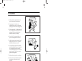
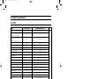
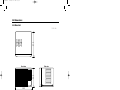
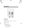
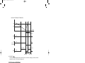
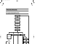
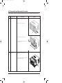
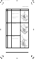
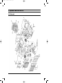
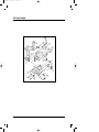
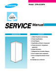
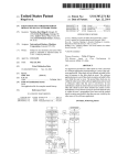
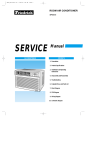
AWH-090ZE/front
6/22/98 3:18 PM
Page 1
ROOM AIR CONDITIONER
AWH090ZE0K
SERVICE
AIR CONDITIONER
Manual
CONTENTS
1. Precautions
2. Product Specifications
3. Installation and Operating
Instructions
4. Disassembly and Reassembly
5. Troubleshooting
6. Exploded Views and Parts List
7. Block Diagram
8. Wiring Diagram
AWH-090ZE/front
6/22/98 3:18 PM
Page 2
ELECTRONICS
© Samsung Electronics Co., Ltd. JAN. 1998.
Printed in Korea.
Code No. DB81-10137A(1)
AWH-090ZE-1
6/22/98 2:11 PM
Page 1
1. Precautions
1. Warning: Prior to repair, disconnect the
power cord from the circuit breaker.
2. Use proper parts: Use only exact
replacement parts. (Also, we recommend
replacing parts rather than repairing them.)
3. Use the proper tools: Use the proper tools
and test equipment, and know how to use
equipment may cause problems laterintermittent contact, for example.
Fig. 1-1 Avoid Dangerous Contact
4. Power Cord: Prior to repair, check the
power cord and replace it if necessary.
5. Avoid using an extension cord, and avoid
tapping into a power cord. This practice
may result in malfunction or fire.
6. After completing repairs and reassembly,
check the insulation resistance, Procedure:
Prior to applying power, measure the
resistance between the power cord and the
ground terminal. The resistance must be
greater than 30 megohms.
Fig. 1-2 No Tapping and No Extension Cords
7. Make sure that the grounds are adequate.
8. Make sure that the installation conditions
are satisfactory. Relocate the unit if
necessary.
9. Keep children away from the unit while it is
being repaired.
10. Be sure to clean the unit and its surrounding
area.
Fig. 1-3 No Kids Nearby!
Fig. 1-4 Clean the Unit
Samsung Electronics
1-1
AWH-090ZE-1
6/22/98 2:11 PM
Page 3
2. Product Specifications
2-1 Table
Item
Unit of Measure
AWH090ZE(COOL/HEAT)
Type
-
Window
mm
520 X 345 X 515
mm
580 X 445 X 580
Volt
220 ~ 240
-
Single
Frequency
Hz
50
Operating Current
A
4.3 / 3.8
Power Consumption
W
1,020 / 860
FREON
R-22
g
510
BTU/h
8,500 / 8,500
BTU/h.W
8.3 / 9.7
Net Weight
kg
36
Condenser
Row
2 X 13
Condenser Fan
Type
Propeller Fan
Evaporator
Row
2 X 12
Evaporator Fan
Type
Blower
W
AMAFS-040AXEA
Model
44H092JW1E4
-
MRA12037-12007
Dimensions:
(Width X Height X Depth)
Packing Size
(Width X Height X Depth)
Voltage:
Phase
Refrigerant Type
Refrigerant Charge
Capacity
EER
Fan Motor
Compressor(Rotary)
Overload Protect
Compressor Capacitor
µF/ VAC
Fan Motor Capacitor
µF/ VAC
30 / 370
(DUAL)
3 / 370
Fan Speed Control
-
Fan speed switch (High & Low)
Thermo Control
-
Thermostat
Samsung Electronics
Remarks
2-1
6/22/98 2:11 PM
Page 4
2-2 Dimensions
2-2-1 Main Unit
515
Unit : mm
Side view
Front view
345
AWH-090ZE-1
520
2-2
Samsung Electronics
AWH-090ZE-1
6/22/98 2:11 PM
Page 5
3. Installation and Operating Instructions
3-1 Installation
* When selecting the area for installing the unit, be sure to obtain approval of the customer.
1.
Make sure that you install the unit in an area that
provides good ventilation.
The air conditioner must not be blocked by any
obstacle affecting the air flow near the air inlet and
air outlet.
2.
Make sure that you install the unit in an area which
can endure the weight and vibration of the unit.
3.
Make sure that you install the unit away from heat
or vapor.
4.
Make sure that you install the unit in an area where
the cooled(heated) air can be evenly spread in a
room.
5.
Make sure that you install the unit in an area away
from TVs, audio units, cordless phones, fluorescent
lighting fixtures and other electrical appliances.
(obtain a clearance of at least one meter)
6.
Make sure that you install the unit in an area which
provides easy drainage for condensed water.
7. Make sure that you install the unit in an area not
exposed to rain or direct sunlight.
(Install a separate sunblind if exposed to direct sunlight.)
8.
Do not install the unit in an area subjected to noise
or vibration amplification which may affect your
neighbor.
(Fix the unit firmly if mounted in a high place.)
Caution:
Do not use the air conditioner in such areas as a greasy area(including machine oil),
saline area(sea side), or sulphuric area(hot spring). When using the air conditioner in these areas,
special maintenance is required. Contact your local dealer or our service center for advice.
Samsung Electronics
3-1
AWH-090ZE-1
6/22/98 2:11 PM
Page 6
3-2 Function Description
Operation control
Thermostat control
3-2-1 Operation control
(1) COOL MODE(BLUE POSITION) :
The air conditioner starts cooling, provided that the room temperature is higher than the selected temperature.
•
( HI COOL) : The fan turns rapidly.
•
(LOW COOL) : The fan turns slowly.
• Thermostat control in cool mode.
Left end : COOL air will be supplied above 30 ~ 35˚C
COOL air will be ceased below 28 ~ 32.5˚C
Right end : COOL air will be supplied above 17.4 ~ 20.4˚C
COOL air will be ceased below 14.4 ~ 17.4˚C
(2) HEAT MODE(RED POSITION) :
The air conditioner starts heating, provided that the room temperature is lower than the selected temperature.
•
( HI HEAT) : The fan turns rapidly.
•
(LOW HEAT) : The fan turns slowly.
• Thermostat control in heat mode.
Left end : HEAT air will be supplied below 14.4 ~ 17.4˚C
HEAT air will be ceased above 17.4 ~ 20.4˚C
Right end : HEAT air will be supplied below 28 ~ 32.5˚C
HEAT air will be ceased above 30 ~ 35˚C
• DEICE function in heat mode :
Deice operation is controlled by sensing the condenser heat exchange temperature and timer.
✻ Deice time is about 5 minutes.
✻ Operating the deice, the air conditioner starts cooling cycle and then the fan stops.
✻ Deice operation
3-2
Samsung Electronics
AWH-090ZE-1
6/22/98 2:11 PM
Page 7
COND SENSOR TEMP(DEICE THERMOSTAT)
8°C
-3°C
TIME
Deice time(about 5 min)
COMP
FAN
4WAY V/V
AIR SWING
ON
ON
ON
OFF
(ON TIME)
TIMER
OFF
50 min
(OFF TIME) (1.5 min)
OFF
DEICE ON
OFF
DEICE OFF
(3) FAN MODE (
)
The fan mode controls dehumidify, filter and circulate room air, with the fan continuing to circulate air while the
compressor is turned off. The fan turns only high speed.
3-2-2 Air swing switch(Option)
On (
):
Automatic ventilation distributes the air flow throughout the room.
(controls the right and left blade-V)
OFF (
):
- Maintain a fixed direction of air flow.
Set the air swing switch to OFF the instant the blade-V come to the desired positioner.
- When the air conditioner starts up in deice mode automatically, the swing of blade is stopped for a moment
and the deice operating is stopped, the swing of blade operates again.
3-2-3 Ventilation switch
Use the ventilation switch when you want to exhaust unfresh air.
Open position : The air inside the room circulates while
exhausted is sent outside.
Closed position : The air inside the room circulates without
exhaust
Open
Position
Samsung Electronics
Closed
Position
3-3
AWH-090ZE-1
6/22/98 2:11 PM
Page 9
4. Disassembly and Reassembly
4-1 Compressor Replacement Flow Chart
Locate cause of defect
Release refrigerant
Disconnect electrical wiring
from compressor
Cut refrigerant lines
from compressor
Plug disconnected lines
Replace compressor
Inspect electrical
wiring for defects,
and terminals for
correct and secure
connections
Solder discharge line
Solder suction line
Use nitrogen gas
Perform soldering function
Problem?
Fill system with nitrogen gas
Y
N
Check for leakage
Y
Leakage?
Corrective action
Check refrigerant oil level
N
Release nitrogen gas?
Low oil level?
Y
N
Evacuate system
Add oil as necessary
Recharge system
Recharge system
Samsung Electronics
4-1
AWH-090ZE-1
6/22/98 2:11 PM
Page 10
4-2 Checking the oil
Fill the transparent container with 10cc of oil, and then conduct the test.
4-2-1 Oil quality
Refrigerant Cycle
Oil Condition
Remarks
Color
Odor
Normal
Light Yellow
No Odor
Return with the system
Over-heated
Brown
-
Oil Change
Compressor damage
Dark brown
Pungent oil
Oil Change
4-2-2 Replacing and refilling the refrigerant oil
1. Replacing the compressor - Do not fill the system with oil as the compressor is already charged.
2. Replacing the condenser - Refill 50cc.
3. Replacing the evaporator - Refill 50cc.
4. Replacing the refrigerant - Refill 30cc.
5. The high pressure side is filled up with oil after the vacuum is completed.
6. When the refrigerant leaks, it is generally not necessary to refill the oil if the leakage is not severe.
4-2
Samsung Electronics
AWH-090ZE-2
6/22/98 2:12 PM
Page 1
4-3 Disassembly and Reassembly Procedure
Stop operation of the air conditioner and remove the power cord before repairing the unit
No.
①
Part name
Ass'y-Grill
Procedures
Remarks
1. Pull out the Guard-air filter on the grille.
2. Remove the Screw on the grille.
3. Push the grille left side and pull up.
4. Pull out the Seal-cabi front between Base
pan and Cabinet.
➁
Ass'y-Frame
1. Remove the 2 screws both side of the
cabinet .
2. Pull the handle at the Base pan to separate
the frame from the Cabinet.
Samsung Electronics
4-3
AWH-090ZE-2
6/22/98 2:12 PM
Page 2
Disassembly and Reassembly
No.
➂
Part name
Ass’y-Control
& Ass’y-Frame
Blade
Procedures
Remarks
1. Remove the Cover-Evap.
2. Remove the 3 screws to disassmble
Ass’y-control and Frame-blade.
3. Separate 3 Ass’y-lead wires from the
Ass’y-control and the deice sensor from
the condenser.
➃
Ass’y-Condenser
1. Remove the 2 screws back of the Base
pan.
2. Remove the 5 screws both side of the
Casing cond and on the Base pan.
➄
4-4
Ass’y-Evaporator
1. Remove the 2 screws front of the PartitionEvap. casing and 2 screws left side of the
Evaporator.
Samsung Electronics
AWH-090ZE-2
6/22/98 2:12 PM
Page 3
Disassembly and Reassembly
No.
➅
Part name
Blower-Fan
Procedures
Remarks
1. Remove the Cover-Evap. case.
2. Loosen the hex. bolt to disassemble the
blower.
3. Remove the 2 screws left side of the
Partition-Evap. casing.
➆
Propeller Fan
1. Loosen the Nut flange.
⑧
Motor
1. Remove the 4 hex. bolts on the partition
and Base pan.
2. Remove the Screw on the Base pan.
Samsung Electronics
4-5
AWH-090ZE-2
6/22/98 2:12 PM
Page 5
5. Troubleshooting
Procedures
1
Check to see whether the electric circuit or electric parts are damaged before repairing the air conditioner.
2
Conduct the following generally to check whether the electric circuit or other electric parts are damaged.
5-1 Troubleshooting Method and Precautions
5-1-1 Checking of power source
Check to see whether the voltage of the power source is 220 ~ 240V, 50Hz.
The air conditioner may not operate properly if the voltage is out of this range.
5-1-2 Check the parts that be weak or fragile
5-1-3 Check the terminals for proper connection
5-1-4 Refer to the table below when there is any malfunction;
No
Trouble
Checkpoints
Possible cause
①
The compressor
does not operate.
1. Check the position of the thermostat.
2. Check the position of the select switch.
3. Check the connection of the lead wire.
4. Check the overload protector.
5. Check the compressor.
1. The setting temperature is higher than the
room temperature in cool mode.
2. The setting temperature is lower than the
room temperature in heat mode.
3. Lead wire disconnected.
4. O.L.P. damaged.
5. Compressor damaged.
➁
The motor does
not operate.
1. Check the connection of the lead wire
and switch.
2. Check the motor.
3. Check whether the unit is deicing.
1. Lead wire disconnected.
2. Switch damaged.
3. Motor damaged.
4. The unit is operating on the deice mode.
➂
The cooling capacity
is low.
1. Check the refrigerant for leak.
2. Check the evaporator condition.
(freezing, clogging with dust, etc.)
❊ The temperature difference between
the air inlet side and air outlet side
should be 12°C at the minimum.
❊ Standard state
Indoor : 27°C, Outdoor : 35°C
1. The leak is caused by a pipe crack.
2. Shortage of the refrigerant.
3. Clean the evaporator, and air filter.
➃
The heating capacity
is low
1. Check the refrigerant for leak.
2. Check the evaporator condition.
(freezing, clogging with dust, etc.)
3. Check whether the drain equipment
(DRAIN PAN, DRAIN TUBE) is installed.
❊ The temperature difference between
the air inlet side and outlet side
should be 12°C at the minimum.
❊ Standard state
Indoor : 20°C, Outdoor : 7°C
❊ Adequate operating temperature
• Heating : Indoor : 0°C~21°C approx.
Outdoor : 28°C or less.
1. The leak is caused by a pipe crack.
2. Shortage of the refrigerant.
3. Clean the evaporator, and air filter.
4. Install the drain pan and drain plug.
➄
Noise
1. Check the vibration of the pipe.
2. Check the propeller fan and blower for
looseness and weakness.
3. Check the motor bearing for noise.
4. Compare the compressor noise with
other compressors.
1. The pipe is in contact with other parts.
2. The tightening of the hexagon nut is faulty.
3. Damage of the motor.
4. Damage of the compressor.
Samsung Electronics
5-1
AWH-090ZE-2
6/22/98 2:12 PM
Page 6
6. Exploded View and Parts List
6-1 Main unit
6-1
Samsung Electronics
AWH-090ZE-2
6/22/98 2:12 PM
Page 7
■ Part List
Q'TY
No.
Code No.
Description
Specification
Remarks
AWH090ZE
1
2
3
4
5
DB92-10006N
DB64-20036C
DB66-60010B
DB66-30037B
DB63-30021B
ASSY-GRILLE
DOOR-CONTROL
LINK-BLADE, H
BLADE-H
GUARD-AIR FILTER
HIPS, SC-94445R
ABS, SC-94445R
ABS, SC-94445R
ABS, SC-94445R
ABS, SC-94445R
1
1
1
7
1
6
7
8
9
10
DB72-10102G
DB90-20193A
DB63-40009A
DB67-30012A
DB67-50051A
SEAL CABI FRONT
ASSY-BASE PAN
TRAY-DRAIN
PARTITION-E/CASING
BLOWER
PO-PU
SECC-P
31-FO PS, WHT
SGCC-M, T0.8
ABS
1
1
1
1
1
11
12
13
14
15
DB60-20019A
DB61-10012A
DB63-10121A
DB67-30013B
DB75-10001A
BOLT-SPECIAL
CASE-EVAP
COVER-EVAP
PARTITION
COVER DAMPER
M6,L11,ZPC3,S45C
FOAM-PS
FOAM-PS
SGCC-M(G90-U), T1.0
PP
1
1
1
1
1
16
17
18
19
20
DB63-10082A
DB67-90003A
DB95-20134C
DB61-30484A
DB61-10029A
COVER-EVAP
REINF-PARTITION
ASSY-MOTOR
SUPPORT-MOTOR
CASE-COND
SGCC-M, T22
SGCC-M, T1.0
AMAFS-040AXEA
SGCC-M,T1.2
PP, BLK
1
1
1
1
1
21
22
23
24
25
DB67-50031B
DB60-30004A
DB96-40172A
DB73-20047C
DB96-30270A
FAN-PROPELLER
NUT-FLANGE
ASSY-EVAPORATOR
RUBBER-TUBE
ASSY-CONDENSER
AS+G/F(20%)
M6,–,SM20C,NTR
2x12 SLIT 1.4
EPDM, –, –, –
2x13 WAVE 1.5
1
1
1
1
1
26
27
28
29
30
DB62-31715A
DB62-40034A
DB95-10065M
DB73-10004A
6021-000124
TUBE-4WAY ASSY
VALVE-CHECK ASS’Y
ASSY-COMP
GROMMET-ISOLATOR
NUT-HEXAGON
AWH090ZE
1/2inch, 30KG/CM2G
44H092JW1E4
EPDM
1C,M8,ZPC(YEL),SM10C
1
1
1
3
3
31
32
33
34
35
DB60-50008A
DB63-20002A
DB67-60020A
DB47-20008B
DB63-10165A
WASHER-COMP
GASKET
SPRING-OLP
OLP
COVER-TERMINAL
ID8.5,OD24,T1.6,ZPC
EPDM,TO.8
STS304-WPA
MRA12037-12007
NORYL
3
1
1
1
1
36
37
38
39
40
DB60-30018A
DB93-50012E
DB63-10355A
DB67-20019A
DB90-10150C
NUT-FLANGE
ASSY-LEAD WIRE COMP
CAP-DRAIN
DRAIN PAN OUT
ASSY-CABI
PI0.8,M5,SM20C
AWM1015 AWG16
CR,T2,BLK
PP
AWH090ZE
1
1
1
1
1
41
42
DB71-40001B
DB65-10010A
BAR STEEL
CLIP PIPE
HSWR,D2.5
SECC-P
1
1
Samsung Electronics
6-2
AWH-090ZE-2
6/22/98 2:12 PM
Page 8
6-2 Ass’y Control
6-3
Samsung Electronics
AWH-090ZE-3
6/22/98 2:13 PM
Page 1
■ Part List
Q'TY
No.
Code No.
Description
Specification
Remarks
AWH090ZE
1
DB64-50131A
KNOB-ASSY
ABS, SC-94445R
2
2
DB61-10030A
CASE-CONTROL LOW
SGCC-M,T0.8
1
3
DB47-20067A
THERMOSTAT
13.8,3P
1
4
DB65-10008A
CLIP-CAPACITOR
SGCC-M,T0.8
1
5
2501-000353
C-OIL
30/3uF, 370V
1
6
DB61-40192A
HOLDER SENSOR
PP BLK
1
7
DB39-10062U
POWER CORD
250V, 10/16A
1
8
DB61-10031A
CASE-CONTROL UP
SGCC-M,T0.8
1
9
DB66-60009B
LINK-BLADE V
SC-94445R
1
10
DB61-60022B
FRAME-BLADE
ABS, SC-94445R
1
11
DB72-10018C
SEAL FRAME
FOPE+FOPU
1
12
DB66-70011B
LEVER-DAMPER
ABS, SC-94445R
1
13
DB64-40042J
INLAY-SWITCH
A1070S, T0.4,NO SWIN
1
14
DB34-90085A
SWITCH-SELECTOR
ASSY, 5P
1
15
DB66-30038B
BLADE-V
ABS, SC-94445R
1
16
DB66-30040B
BLADE-VH
SC-94445R
1
17
DB47-20068A
THERMOSTAT-DEICE
3P
1
18
DB45-10009A
TIMER-DEFROST
D2506, 50/60Hz
1
Samsung Electronics
6-4
6/22/98 2:13 PM
Page 3
7. Block Diagram
7-1 Refrigerating Cycle Block Diagram
Capillay tube
Heat
exchanger
(Evaporator)
Heat
exchanger
(Condenser)
Propeller fan
Check V/V
T1
fan
AWH-090ZE-3
T2
4-way valve
Compressor
Samsung Electronics
Cooling
Heating
7-1
6/22/98 2:13 PM
Page 5
8. Wiring Diagram
F.M
WHT
YEL
ORN
WHT
YEL
ORN
2
S
R
3
1
BLU
RED
RED
H
M
S L
O.L.P
BLK
WHT
RED
BLK
WHT
RED
C
BLK
COMPRESSOR
BLK
GRN
THERMOSTAT
8-1 AWH090ZE
4
DEICE TIMER
BLU
BLU
RED
BLK
SOLENOID-COIL
6
SELECTOR-S/W
1
RED
GRN/YEL
PLUG
GROUND
AWH090ZE CAPACITOR DUAL : 3/30µF
Samsung Electronics
8
GRN
4
BLK
YEL
ORN
2
SKY/BLU
RED
GRN
BLU
4 5 3 2 1
RED
GRN
BLU
RED
RED
2
3
RED
DEICE
THERMOSTAT
BRN
1 YEL
BLU
WHT
CAPACITOR
(DUAL)
BLU
ORN
RED
GRN
YEL
AWH-090ZE-3
X
370VAC
8-1