1
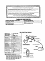
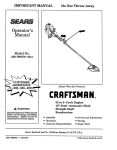
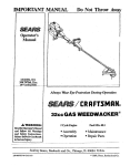
IMPORTANT MANUAL
Do-.Not Throw Away
Operator's
Manual
MODEL NO.
358.797150-32cc.
_7_ CuU_ _t_)
Always Wear Eye Protection During Operation
,_,gJ i-CRR
FTSMR
32CC GAS WEEDWACKER
& WARNING:
Readtl__sManml
_
FonowAnWam_
and Saf_y
Instructions.
Fa_TO
Do So Can R¢_
Sears, Roebuck
2 Cycle Engine
Fuel Mix 40:1
"Assembly
"Maintenance
• Operation
• Repair Parts
and Co., Hoffman
Estate,
IL 60179
®
TABLE
OF CONTENTS
WARNINGS
AND SAFETY INSTRUCTIONS
.................. 3 GENERAL
MAINTENANCE
..........................................
KNOW YOUR TRIMMER ..................................................
6 TROUBLE SHOOTING
CHART .....................................
ASSEMBLY .................................................. :......................... 7 REPAIR PARTS LIST ........................................................
ACCESSORIF_;
................................................................
I0 INDEX .................................................................................
ENGINE [NFORRLATION
.................................................. II
QUICK REFERENCE
PAGE .............................................
USING YOUR TRIMMER_
13
17
22
23
26
27-
,,,
L
i
iiiiiii i i
imllll iiiiiiii i iiii iii i iiiii
IIIIHIII
I II
I
I IIIII I
.m
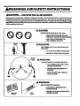
kWARNINGS AND SAFETY INSTRUCTIONS
_I
AWARNING
I
-- _
PO_
I IIWJll
I
._
TOOL__LNG/ZO/_
Thlstooi cancau_ seriousinjuryor blindncsstoth_opemtor andolh¢_ Thevmrn_ _ _
__
musfl_ followed Ioprovide _asona_ saf_ andefficiency in using this u_ol.The ol_ra_r is _
wamin_ and_
inthis manu_ andontl-ae_ool.Readtheenflre Operator's Man_ _
__
lhislooU l_r_
theuse oftl_s power tool topersons whoread, undersland; and follow _ _
In fl_rsmanual and on the tool
in_is _
_ foll_
_
_
_
_
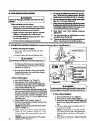
A DANGER
NEVER U_'BLAD_
_
_
TOOL.
-- THE BLADE CAN COME OFF AND
SERIOUSLY INJURE YOU AND OTHER_
-- THIS TOOL IS DESIGNEO FOR,
LINE TRIMMER USE ONLY.
Aw (;
THE TRIMMER LINE CAN THROW OBJ_'CTS
VIOLENTLY.
-- YOU CAN BE BUNDED OR INJURED.
-- WEAR EYE AND LEG PROTECTION..
ZONE
AW_G
HAZARD ZONE FOR THROWN OBJECTS.
-- THE TRIMMER
LINE CAN THROW
OBJECTS VIOLENTLY.
--_ OTHERS CAN BIE BUNOED OR
-
iNJURED.
_-KEEP
PEOPLEAND
3O FEET-AWAY,
ANIMALS
RF-AD OPERATOR "SMANUAL.
--+-!I_WRUCTIONs.FOLLOW
ALL PI_FINIHGS AND
,-
/
_/
+
-- FAILURE
TO DOSOCANRESULTIN
smouslmu .
.................................................
,,,,,
& WARNINGSAND SAFE
--
_]ects
immediately if y0u are ap_oached.
3. Alwayslmepthe¢r,gineon therlghtskleofyourhedy.
4. Holdthetoolfirmlywithboth_
5. Do not _
or use from unsm_ surfaces such as
ladders, trees, steep slopcg _
etc. Use exwa care
when deaning on stairwa_ Keep firm_andbalance
at all times,
6. Keeptrimawa"
head bdow waistl_vel.
7. Do not raise _',,€engimabovcyour _ist, Theuimn_ head
can corr_ 0aagenmsty close toy0ur body. "
muffler whentheen#ne is running.
"
...... 9. Use only forjob_ cxplained in this mamiaL
A
_AL_S_L.Ik"Jg_,
l. Maintaia the tool according to_
procedures.
Keep the trimmerline at the proper length.
2. Never start the enginewith the clutch shrtod remove. The
clutch can fly.apartand cause serious'injury.
3. _
thesparkplugheforeperfom_ maht_mnce
except for _r
adj_ts.
4. Make carburetor adjustments with the drive shaftho_ing
supported toprevent the trimmerline from cotaacting any
object. Hold the tool by hand; do not use the optional
shoulder strap for support.
5. Keep others away when making carburv,or adjumnents.
6_ L]_ o_ly genuine tep!___t
rm_q__ recom_men.'!,_o5
bySears.
7. Have all maintenance and service not explained in
this manual performed by your Sears Service Center/
D_partment.
•&, TRANSPORTING
AND STORAGE
L _____m_k_
_f__.t_ _<,I
t_r_ _
ina_el_de
or_a_
3. Beforestming thetool, useup fitel left inthe fuel lines and
carbu_
by starting the engine and lettiagit run until it
& FI,'I SAggrl"
!. Move at least 10 feet awayfrom fueliegsit_ before smrtiag engifie.
stops.
4. _ofe rod and furlin an area _
fuetwapotscannommch
sparksor open flames from water heaters,electric motors
2. Useacontainer_
forfuel.
3. Do not smok_orallowsmokiag nearfuelor thetool or
whileusing thetoot.
orswitches,farnac_ etc.
5. Store the tooI su the line limiter cannotaccidentallycaase
injury. The tool can be huag by the drivesha_ h_ing or
4.Wipeup allfuel
spills
before
starting
eagine.
6. Storetool out ofreach ofchildren.
.....
..engine
to coolbeforerefueling.
•"-6_
Run fuel
out of the fiwJsystem before storing the tool.
" 7. Storetoolandfuelinanmeawherefuelvaixxscannotreach
sparksor open flames fromwater heaters, electric motors
or switches, furnaces, etc.
I
,,I
hejpersoutsidethe60 footHazardZone.Stoptheengine
a_achmeats as recom_aded for
to,'bratlonsthr_agh_,o!on_ useor__,hand
,
• rowa or b_om_ entaagldd ia the trimmer head.
2. Keep others including children, animals, bys_gters, and
8. Xeq,othmmwywhen
ma_ c_-bum__justm_as.
I_
,
(rocks,brokenghss. nails,wir_ string,e_)which canbe
_5. Useo_ thespech_ uimmerhead.S_ _"
-9; Use onty accessor_r
this toot by Sear_
, ,,,,,
1, hspect the area to be cut hefore each use. 1_
3. Donot_a-at_ thistoolwhea_a areti_, in, ortraderthe
Make sure ff_ _immer head is properly instal|edand
fastened. Refer to "Assembly"
6. Be.surethe trimmerhead stops turningwhen engineidles.
See "CarburetorAdjustments."
7.Mal_ carhuct_adjusanents
withthedrive
shaRhousing
supported toprevent the trimmerline flora contacting any
objecLHold thetool
byhand;.do notusetheoptional
I
A ¢U'/T/NG_
I. Always wear eye protectionwhen operating, se_icing.
or performing maimenance on your unit.
2. Keep hair. fingers, and all other parts of the body av,W
from openings aM moving parts. AIv,-ayswear heavy,
long pants, boots, and gloves. Do not go barefootor wear
sandals, jewelry, short pants, loose clothing, or clothing with loosely hanging straps, ties. tassels, etc.: they
can be caught in moving parts. Secure hair so it is above
shoulder length. Being fully _red
will help protect
you from pieces of toxic plants (such as poison ivy)
thrown by the TrimmerHead, which could be more of.
a hazard than touching the plant itself.
I. Inspect entire tool before each use. Replace damaged
parts. Check for fitel leaks and make sure all handles.
guaM.s,and'fasteners ace in place and securely Fastened.
2. Replace trimmer head parts that are cracked, chipped,
brola.m,or damaged in any other waybeforeusingthe tool
3. Use only .080" diameter Sears Laser Line.. Never use
wire, rope, string, etc.
4. Be sure the shield is properly attached.
,|,,
INSTRUCTIONS- .
A OPERATOR SAFETY
influenc_ of alcohol, drugs,or uxxlication,
- 4. Alwa_ use the assist han01e.See 'l_ssembly?'
5. Wearhearing protoctionifyouuse this tool for more than
1½ hours per day,
6.Nevtrstartornmtheergir_ihsid_$aclosedmomorbu_ding. Bri_athiagexhaustfumescanldll.
7. Keep handles free ofoil and fuel.
,,,,,HH
lf si_at_ns ocrurw_,ch are not co_ered ln _ts _mml, _se
care and good _¢men_
Contaa your Sea_ _er_ce
C.ntedt_
_
i_you need asslstimce.
.c_. d cau_blood vessd ornervedamagem_ _
ott t ,
l
l i
ulm,,1111ul
IIIIII
I f
"
IL,I111'II
1111 _ 11
i iiiiiiiii
11 1i 111
l ill i
. ......................
ii
L ii
+
iiiiiiiiiiiiii
i
-mow mum'rammvma¸
I
II
lllllJ
J
I
I
II
IIII
IIII
I
I I
L
lllllltllll_
_
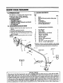
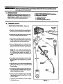
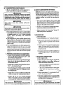
•L INTRODUCTION
Your Trimmeris a versatile product designed to help
you give .yma-lawn a finishedappearance.
trimming
scalping,
sweeping.
spec veat.r=s
• _
O.tch
• Albp0sitimCartmr=_
• AdjustableAnfl-Vibe,cushiemaed
Assistltandle
• Autmnatic Line Feed
• 17-C.tangl"ath
II. UNPACKING
J
ii
ii
iiiiiii
I
I Illllllllll
Illllll
KEY
No+
fir,,,.
I
Eag_
1
2
3
4
5
Ihive Shafl/llousing Assembly wlSafety Label
Shield
Ts_r_ Head
2-.cydeF__ Oil
1
1
I
1
--
Opemor'sManual_
1
--
LoosePamBag _ot Show_)
Shown)
t
INSTRUCTIONS
_
1. Remove contents from the carton if you have not
doneso. +
/_
C. CA1L'rON C.O_
•
2. Check vans againstthe li_ bekr,,v. •
3. Examineparts fordamage..D6 notuse damagedpans_
4. Notify your Seam Store immediately if a part is missing or damaged.
NOI'E: Itis normal to hear the fuel l'dterrattlem anempty
fuel tank.
PARTS BAG G3_:
6
' FIexShaflL.bc
7
8 ..
: Screw-Shield
Bracket+Shidd
:.
_.
9
SquareHeadScrew- Ks._istHafi_el
10
11
12
13
14
15
16
17
Hex Nut- Asslst Handle
+ T-Handle- Assist Ha.,_e
Hex Screw - Engine
HexNut - Engine
+
Dust Cup +IMive ShaR Housing
Rex Wrench
Hex Screw - ThrottJ¢ Tdgger Housing
Hex Nut + Throttle Trigger Housing
1
2
1
1
1
2
2
I
1
I
1
*Hardware is shown in actual size drawings in the assembly
insUuctions_Compare the hatdwar_ imhe 1oo_ pare hag wi6__e
-hardware in thedrawingsto determine6_e correct Fartto use.
!
\
D
16
7
6
=
For users
SPECIAL NOTICE
on U.$. Forest Land and in some states, including California
(Public Resources
Codes 4442 and 4443),
Idaho, Maine, Minnesota,'Ne_
Jersey, Oregon, and Was_ngtom
Certain internal combustion engines operated on
forest, brush, and/or grass-coqered land in the above areas ar_ required to be equipped with a spark me__or, maintained
in effective vmrking order, or'th% engh'm:must be construct_,
equipped, and maintained for the pr_eation of fire. Check
your state or local authorities for tegu!ations pe_
toLt_
requirements+ Failur_ to follow these requirements
is a violation of the law. This unit is not factory-equipped
with a spark arrestor; however, a spark arrestor'+isavail+
able as an optional part+ If a spark arrestor is required in your area, contact your Sears Service Center or Parts _..............
7
_7-
_,
+
...................................................................................................................................................
II Illl!lllllllllllllll
II Ull
Illllll Ill
I
II
Ill
Illll
- II
I
_tslmltm_
i
I
I
forthe_)
I Jllllll
IItlllt
IItIllll
I
L itqlglP_
_ _'s°M_
z_s_
Ill
I
I II
I. luta_
d_.Zof_dtohctp_u
dm _
H
..........
IIII II
Ma.tetlal.
my.
ii
i!,.i
b. Adjustable wrench."
c. Hot,Wrtnch provided with tool.
i
i
H
II
• 1. DR/VE
II
readtl_ endremanual_ I_omc
familiar
_iththetool
i_.fole
youbeginassembly.
B. ASSEMBLY
iii
l'OOIt _'g
=,a'=a,
.asScm_€ the tool and io provideitssafe operation, it is
_
II
IIIII
,Ill
I
Illll_
I
,,I,
I
,,ll II
I
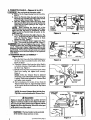
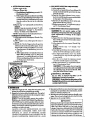
STEPS
SHAI_
HOUSING
.-- Figure
1
DmV_SnAlzr
HO_._ING
a.. Piacethe two Screws (from the loose parts bag) into .
theholesontheClmchShr6udasshowninFi_e
1. L
.b. Position the Ix_k:Nuts (from the loose parts bag)
in the hex openings in the Clutch Shroud.
RIDGE
c. T_hten tim_wwswith the small hexwrench provided just enough to hold thehardware together while
holding the Lock-Nuts with your other hand.
d. Remove the shipping cap from the straight end of the
Drive Sha_ Housing. Make sure the Flexible Dri'_x:
Shaft d,_
not f_l out
r_,_-_ _
NOTE:
_of
Dirt on the Shaft will significantly
reduce
the tool. If the Flenu'ble Drive Shaft fails out
of the Housing, clean,, relube_ then reinstall. See
Ftexa'ble Dri_?eShaft Lubricalicm" ia the Maintenance .r_-t.ion.
e.
"lMm Handle around and position the Drive Shaft
Housing with the Arbor Shaft down as shown in
Figure. 1.
Align the bottom glXXWeon the Drive Shaft Housing
with the ridge on the inner lower wall of the Clutch
Shroud opening.
g_
_theAex,rS_.
_ _to
ati_thesqua_
end of the Flexible
DriveShaft with the square inside theClutch Shroud opening.
h_
I
I
!
!
I
I
Shroud until it contacts the Foam Grip or is within
1/8 inch. Figure 1.
i. Tighten the Screws alternately with the smal[kcx
wrench until secure.
Igigtlre
1
7
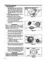
iCAUTION:
| Do not bend the throttle
cable.
a. Slid_ the Throttle Trigger Housing from the Foam Grip.
Figure 2.
.
b. Insext the Throttle Cable through the tunnel m
the Foam Grip until the end of the Cable extends
at least 2 indies beyond Grip. Figure 3.
c. Hold the Trigger away from the Drive Shaft
Hou_ing
andtheinsert
the opening
barrel end
Throttle
C_le into
round
in of
thetheTrigger
as
shown in l_ure 3..
When insexting
the
barrel end
of the
"
,
Throttle
make sure that the barrel is completely inserted
(I_.._tre 4)and the Throttle Cable is located in the
split m the Arm.
d. Push the Cable backinto the splitin thearm. Figure 3. Guide the arm into the Foam Grip tunnel
until the Throttle Trigger Housing is flush
against the Grip. Figure 5.
e. Squeeze and hold the Trigger against the Foam
] CAUTION" ] Do not overtzghten
the screw. There
must be at least 1/8" free pla_. in the tagger.
Fig_
GHp. Then install .th.e_and
Nut Figure 5.
_er
can fully return to idle when the trigger
xs
released_
must thenotoperator
turn at
idle speed to The
avoidtrimmer
serious head
injuryto
and others.
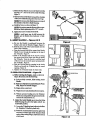
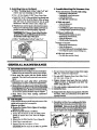
3,TRIMME_
_dfl_tEi: HE&
HEAD mn_ SHIELD
-"
FJlDII"q_ 6-,_ 7
a. PLacethe Dust Cap on the Drive Shaft.Housing over
the hex nut that is assembled onthe Arbor Shaft.
Figme 6 Onset)
b. Thread the Trimmer Head onto the Arbor Shaft in
a clockwise direction. Hand tighten firmly against
the Dust Cup. Figure 6_
c. Hold the Dust Cap with a wrvnch to keep th¢ Arbor
Shaft from turning and tighten head secuwly.
Figure 6.
NOTE: Unless the Trimmer Head is tightened
adequately, it can unthread the first time the engine
is started. If this occurs reinstall the Trimmer Head
• a.-A tighten more seeu,_Iy. "
d. Pull a minimum of 4 inches 0f line from the
Trimmer Head. Figure 6. Approximately
2 inches
of line can be advanced each time the Tap Button
is pressed_
NOI_ To remo_ Trimmer Head, hold the Dust
Cupwitha wrench aadtmthreadtheTfimmer Head.
_WARNING
Failure to imtali the shield in the position shown in
Figures 7 and 8 can result in serious injury to the operator. The length of the shield must be aligned with the
of the shield toward the engine.
L_o.:l
TheL_e 'r_i_ (onthe_
otthe shietd) is sharp and vm cut you.
( continued next page )
[
Foam
-
IPigu_
\\X
-
Round Hole
nd of
_'1L_3
_
__
__
_+--_.%_
"::?_
WRO
Screw
Figure
4
1/8" Play "_
Flgurt S
_6
!
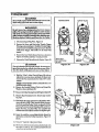
€. Match the Key (Raised area) on the Shield with the
Keyway ("V" slot) on the Drive Shaft Housing.
l_gure 7.
f. Restthebotto'moftheShield
ontopofthe shoulder
of the Drive Shaft Housingabove the Dust Cup.
NOTE:Ihe boaomofthe Shield must rest on topof
the shoulder of the Drive Shaft Housing.
g. lnstatlthe _
asshownin FIgure 7.
NOTE:It is easierto starttheScrewswitha _driver and finish ti&htcning with a 3/8" w_nch.
h. T_m:n the 5crows evenly and securely.
NOTE: A small space may be left between the "
Bracket and the Sl'deld when hardware is fully
Eigh ae .
5. _swr_-,rtzu_
_ a e_9
a. Be sure.the Handle is positioned bi_ween the
Safety ISabel hind theTlirc_fle
Trigger. Figure 8:."
b. Push the lower end of the Assist Handle onto the
Drive Shaft Housing.
c, Drop the threaded end of the square-head Assist
Handle Screw through the opening in the top of
the T-Handle. Figure 9.
d. Pull on tl_ threaded end of the Screw to bring
the square head of the Screw past the pin inside
the T-Handle. Twist the Screw to seat the head
of the Screw in the recessed square opening inside
the T-Handle. Figure 8.
e. Push the Nut into the hex opening in the Assist
H_n_dle and instal! the T-Handle into the round
opening. Figure 8.
f. Tighten the T-Handle firmly by hand only.
lrllurcS
TOPVIEw
OF
T_
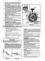
6. OPEKA_T_G POSITION .- _
a. Bd_
F_
starting the Englne, stand as _
10and check for the follovdng:
l). t_ arm_
ex_ndea,_
hol_
in
Assist
•Handle.
2). Rightarm slighdy bent, handholding the Foam
Grip, fingers on ThrottleTrigger.
3). Enginebelo_vwaist level.
4). Weight oftool evenly distributed between _
5). Without operator bending over, the Trimmer
Headis near _axlparalId to theground and eas_y
b. Aaljest tl_ Asdst _
up er downtl_ D_
Shaft H_ng
(but above the Salty Label) to a
comfortable position.
1). Inosen the T-Handleby hand, adjust Asdst Hartdie. Retighten T-Handle by hand oth_
2). _
fl_e Assist HaMle from le& to right flit is
necess_
to tilt _he angle ofth_ Trimmer Head
such as when curling a large, sloped area such as
a ditchbank.
r_p,_r_zo
i
T
"
i
i
ii iHi
ill
li
"
imiHiql
ii
•
ii I
liNiiii
ii
ii
HHII
lllIHIL
I
ACC kqORIES
The following accessories a_ availablethroughSears RetailStores, CatalogOutlets, or Service Centers.
ITEM
STOCKNO.
Safety Face Shield
:
..
9-18613
gafety Goggles....... .. ...........................................................
.
2-Cycle Engine Oil .................................................
Spark Plug ......................................................
. ....
.
....
..
9-1859
71-30143
_.............
.
.
..
Replacement Trimmer Head (available only through Sears Service Centers) .......
.......
Replacement
.080" Dia. Nylon Trimmer Line
-- 400 ft...................................................................
. . ..
200 ft.
..
100 ft.
.
.
Replacement
Spool with Line
Shoulder Strap Kit. ....
..............
Flex Shaft Lube
Spark Arrestor Kit .-,...
.
_.. _. _/ .-.. _ ,
: .....
•
o
.
.
*
71-85854
71-85805
71-85778
71-85608
71-85771
71-85815
71-85783
530-030102*
952-701612*
*ArgUable through your SEARS SERVICE
NOrF.,S
,
,_,
•
ENGINE
INFORMATION
i
A. FUELING
1.FUEL
I iiiiiii ii
YOUR ENGINE
3. USE THE FOLLOWING
SEARS CRAFTSMAN 2-cycle
engine oil
mixed at 40:1 is stronglyrecommended.
Consuit the in.structions on the oil container for
Rroper nnxmg.
SAFETY
a.Useonly recommended fud mixtures.
b. Mix and pour fuel ouldoors and where there are
nosparks
orflames.
1 PART OIL TO 40 PARTS GASOLINE=
3.2 ft. oz. oil to I gallon gasoline
8.0 ft. oz. off to 2.5 gallon gasoline
c. Use a container approved for fud.
d. Do not smoke or allow smoking near fuelor the tool
or while using the tool.
e. Wipe up all furl spills before starting the engine_
Not all air cooled 2-cycle engine oils ha_'e the
same qualities. If SEARS CRAFTSMAN 2-cycle
engine oil is not available, use a good quality,
2-cycle engine oil recommended
for air-cooled
engines. Mix at a ratio of 40: I (3.2 oz. oil to i
gallon gasoline).
f. Move at least 10 feet away from furling site
before starting engine.
g. Stop engine before-removing fuel calx Allow
the engine to cool before refueling.
h. Before storing toot; use up fad left in carbm_
lor by starting engiffe and letting 'it run until it
stops.
i. Store tool and fuel in an area where fuel vapors
cannot reach sparks or olden flames from water
heaters, eloctdc motors or switches, furnaces, etc.
• . FUEL
4.DO
• Genuine Sears40:l, 2-cycle engine oil is str_
recommended for the protection,of your unit.
Exte_iveengineeiingtestshavepi_veathat
Sears
-2-cycle erigine o'flresists brzak-downa_-operatlng
in d_le
l_rforulanc_ and longer engine life.
• Gasoline must bedean and not over two months
old. Aftera short period of time, gasolin_willchemically break down and form compounds thaf_ause
hard starting _ damage in 2-cycle engines.
s The correct measure of gasoline to Oil is very
important. Too much oil in the mixtu_ will foul the
spark plug.
ICAUrloN:] Too little oH or incorrect
cause the engine to overheat and seize.
oil will
N0T
USE:
" NMMA Oil-- National Ma'-ine Manufacturers
Association (formerly BIA)
-- Does not have proper additives for 2-cycle, aircooled engines and can cause engine damage.
- AUTOM{H_rE
OIL__
MAXTIJRE
• Your tool is powered by a 2-cycle engine which
requires a furl _
of regular unleaded gasoline and a high qu_ity engine oil specially made
for 2-¢ycle_ air cooled engines.
The internal design oftbe 2-c-ycle engine requires
lubrication of moving parts. I__brication is provided
when the reoommended mixture ofgasol ine andoil
is used.
ONLY:
-- Does not have proper additives for 2-cycle, aircooled engines and can cause engine damage.
CAIJTION
Experience LridlcaL_ Lhatalcoho! bknded fuels (_
gasohol or us_tg ethanol or methanol) can a_'act
moisture which leads to separation and formation of
d
Ad egas
the
syswan _ an er_ne while m storage, q[b avoid
probl_s,
do not leave furl in the unit when storing for
30 _
or longer. Start the engineand letit rnn unl_l the
User h
season. ;see the
Storage" si_ion for
_afm'mafion,-Neveruse
englne.or _
.prodncts
in the fuel tank-:Or permanent
"_
OCCUr.
. tt
cleanerdamage
NOTE: ff you do not want to remove the fuel from
your unit, SEARS CRAFTSMAN Fuel Stabilizer
(#'/1-33500) may be added to fuel left in the tank to
minimize gum deposits and acids. If the tank is almost
empty, mix stabilizer with fresh fuel ina_parate container and add to the taidc.
.5. HOW TO MIX FUEL AND FILL TANK
:<_
Do, nOi__Taixgasoline and oil directly in
the fuel tank.
a. Pour the proper measure of engine oil into an
approved, marked fuel containei'. Then, fill the
container with regular unleaded gasoline.
If fuel is already in the container, add the
proper measure of engine oil. Then, close the
container tightly and shake it momentarily.
b. Slowly remove fuel cap.
c. Using a spout or funnel, fill the. fuel tank with
fuel mix.
d. Reinstall the fuel caps securely.
I1
•
I lll l
B.
I ,
I ,H,,
IIIIII
,
lli
IIIH,,
III
PIglDOPERATION
,
I
,,
IIIIIIIIIIIII
II HI
ill
I I IIIIIIIIIIIII
I
_
sat_ _n_om
_ _
_WAKNINO
maual.
See_
2. M,d__
8,
C," b"rARTING
,. mm,re,mrttng
away
when
from
by hand; do not
maklag
carbur,_
or a_
as rteom-
_
byS_rs tot tl_tooi.
i0. Oem thealrmmitalr_ beforeoimattngthetool.
'
to _'Specifieations,"
.,,,,.
(For location
ethers
9. Useonb,_
IIIIIIH
INSTRUCTIONS
Keep
u_ object. Soldtl_tool
adJastmm_
use sci_, rope.,string,
4. Use only with the slMeld properly attached.
t*Wm_tr_mm_ae
tonlmatng
SearSLaser
Llne®.
Never
mll
adl,,stna_,wah thedrtve,hart
hms__
trimmer head parts that are cracked,
or damaged before using this tool.
ii
t, _
uk,. see'camam, M_"
I
1. _
the ¢mt_ tool b_ore _
me. l_la_
damagedparts. Check for fuel leaks and make sure ai!
fasteners are in place and secun:ly fas_ned.
3_Useoral?
J_O"_
head
tastamd,ad,ma_
_
Re_to'_emb_." "
Cx Be_ trhnm_ laad,*m- tara_ wheamMae
l_tore opera_ _m- tool, always:
2. Replace
chipped,
[llllllili! I i
5. U,,mly_,pedaed_hm_
CHECKS
tiom." Make sure the trkam_
_dew -a wma_
I
of €ontnKs,
,,,,,,,,
for air ffl_
....................._.....
location.
_
,
,,,,,
,
refeir'to "_tions,'_
the en_e.
a. Fuel engine. Move at least 10 fee[away
fueling site.
from
b. Extend 4-6 inch_ of Line from Trinmaer Head.
I
[ Thetrimmer
head w_turnassoonasti_englnestarts."
e. Rest Engine and Shield on grotmd, _
Trimmer Head offthe ground away from trees, bushes,
onlookers, e_ F'igu_ 11.
ON/OFF
d. If using optional
Shoulder Strap, place Shoulder
Swap on your shoulder. Start engine before clipping
&%oulder &trap tothetool.
2,.1F_r a Cold Igngin_
a. Mo_,_ OrdOffS_'itch
to "on y Figure 12.
Ix Move Choke to "full'* position. Figure 13.
._ GtasptbamGripandsquee_ThroaleTriggerfully.
Ktep lhrottle
Tn'gger
fullysqueezeduntilengine
•n_unoo_
.
(_roushsu_%9.
d. Pull Starter Ropesharply untilengine attempts to r_,
but no more than 8 lmlls at full choke to avoid flooding
theengir_ The engine 'in, tempt tarun "maybehard..
to heat:. The operator must/iste,
_
After 8
pulls, proceed to step "e;' even if engine has not
I Avc&l
. any _
a warmenglne.
"
__;:V. Move Ch6__'"half'
po?ition. Figure 13.
f. Pull Starter Rope sharply until engine attemps to run,
but no more than5 pulis.
NOYE: Ifengine has not started ate5 pulls, repeat
mps '_-thro_..f:'
12
g-Allow engine to run 10-15 seconds, then move
Choke to "off" position,
Figure
13. Keep
Throttle Trigger fully squeezed.until
engine runs
smoothly.
"
"
.i._.._
NOTE: If_-gine dies with _
at "off" position,
reoeat,q_ns e thrca
..............................
3. _
(_dm:t wi_lbemuffler
A hot mufl_cancau_
w_
"1"
s_fing
im_.
aWarm_
a. MoveOniOffSwitch
to"on:' Figure12.
b. Mo_Cnoke
to"t=ll _ posltion<:E_u_
I3..._:,_21
c. Grasp
r_amc__ an__
Thro_Tri_ _
K_ep lhrottl¢ Trigg¢r fuily squeezed unal ens_
runs.
d. P_II Stm"ter Rope sharply until engine runs, but
no more than 5 pulls..
NOTE: If engine does not mn after 5 pulis,
it is probably flooded. Wait a few minutes and
repeat procedure with Choke at "off '" position.
'_
Figure 13.
e. Move Choke to "oW'position. F_m_ t3.Keep 7h'g:_..........................................................................................
i uul_
Ill
, ,,,,,,±
nn
U II HU
A.LmE__
d..Makesure the_mmerl_adh propedyinstalled
and securely fastened. Refer to '_,ss_ably:"
a.
Alw-a_ _ar eye protection when operating, _rvieing.
or performing maintenance on your unit.
e. Besure me trimmer beadstolpsturn_when
b. Keep hair, fingers, and aZlother parls oflhe body away
from openings and moving parts. Always ,,,,,carheavy.
hmg pan_ boots,andglc_es_
.Don_ gobarefoot
orwear
.sandals.
jewelry,
shortpants,looseclothing,
or cloth• ing with h_)_ly hanging s_mps, ties, _¢ls,
etc.: they
can be caught in-moving parts. Secme hair .so it is above
shoulder leith. Being fully co_d
will help p_ect
\.Lm from picccs of toxic planL,_(s0ch as poison ivy)
Ihn_'n by thc Trimmer H_._d. which could be more o[
a h:.oard than touching the plant h._lf.
.
f. Make carburet_ _ustmenls w#h the drive
-shalt
houa_ mpl_,_ tol_eve_theivan:
met Unet_m coutact_ au_ object. Holdd_
tc_l wi_ ycgr lured;do not use 0_ optional shoul-
d_ s_
adjustments.
-.
h. Use only accessories or attaclunents as recommended forthistoolbySears.
3.curn_..
m, or under the influence of alcohol, drugs,
•
fors_n.
_ Keepothers away when nudaugcadva_-tor
c. Do not operate this tool when you are tlred,
or _.
"
."a.:Inspecttbeareato
becatl_roreeach
use.
_
indangerofloslng
yourbahnce.................................
which _ be _
t6mmer head.
e. Never start or run the engine h_ide a dosed r0om
or building. Brr,aihing exhaust fumes can kill.
f. Keep handles free of oil and furl.
Insp_"c!entire [<×d i_G_ each u_. Replace danmgcd
paa__.
Ch_k fi_r fucl Ical_s and make _ur¢ all handl_.
guard_, and lh.,;ter,.ersare in place and _curely lhstcncat.
b. Use only .080" dianmler Sem-s l.zaser IJne, Never
use wire, string, rope, etc.
i
Illlll
I I
8. _xrros_mc
H
_
Ill
II
lul IHIHll
the toot firmly
theright
with _
d. Keep gnnm footingandbalam_
sideofyour
hands.
Do notov_r-ccad_
e. Keep tl_ trimmer head bdow wai_ levd.
f. Do not ra_ the engh_ above your wa_.
• g: Keeo_UOartsor_ourbod_aw_rrommeOdm_
_neandmum_ _a_
,,,,,,,,llllll I
lllllJl.................... •
_J_vAs_c_
m_ne h_
lUlUl IIIII
_WA._nqG
.-_ Thetchnmerlineadvano_au_ast_ine
of line will not advance _
wears andn_duc_sth_ cu_'_g path.
. _
enum_ledin the
h. Useonly for _bs_e_lained in thlsmanual.
c. Besure the shield is properly attached.
i
Oi_
.-b. Alwayskeeptheengineon
body.
c. Hold
a.
the
engine idles. See "Ca.,buretor Adjusunents."
and can cause serlous
Thelinewillwearfasterandwilladvancemorefre_
rope, etc. W'_ can breakoff._._tt_
quen_wlw.ncuni_against
hardsurracessuch
as "
become
and
a dangerous
•rocks, bricks,concte_ metal fences, etc., thanwhen WARNING
cuuingagaln_x_y objectssuchasueesor_n
feax_.
If line does not advance properly:
- Opem_theen_e atfuUdxroale
andallowtheline
to strike a hard surface such as concrete or the_
e_c), whkh can damage to the trimmerhead, become
:mtangl_ in the _
or be throwncausln_ a serious
h3_rd;
""
"'" "
ground.
-- ffline is4"or less, stoptheengine
and check for line
binding or tangling on the spool. See "Tdmm_r
Head"in the MaintemmctSection
6>r'_vinding
operated. Figure 14.
Flk,ur_ 14
4, woea w_trmgngin.(_
eCguelg
ttmuit_oat
a. Refuel engine. Move i0 feet away from the fueling site.
f. Move Chok_ m "olin' _.
b. Move Igni'fi0nSwitch to "on?'F_e 12.
c. Move Cho_ _'_11" position. Ftgure 13.
F_gum B.
g. Punstaa_ P_e un_ mginenms,_nomoretha
d. Grasp Foam Grip and squeeze "I]l_roUleTrigger
fully. Keep Tluoule TrlggerfulIy squeezed until
enSine runs _c,
NOI'_ Ifeagi_ has_,
.th_
-
e. eaq Stamraopesha_ly Lm_e_ne atten_ to
cedu_withCho_ _t"on" posi_. F_,ureI3.
ran, but no more than 5 pulls.
L_III
II
pull
_ar_ RoI_
5.mo_ l_. _gin¢ _ do_ aotraa,
itisprobably
hooded. Wai.ta few minutes and iepeat pro,
II
Im •
III,I
LU
III1,,,,,111IIII
I
II
_illllllll
iii
|' ' ,,,,,,,m,H
,
ill
i _
Ik OlPgRATINGINSTRU_rlON$
I. Before entering the material
2. Atwaysrdeasetht Thro_ Trlgger_d anewthe
to be cut, bring the
¢*_
engine to cutting speed by squeezing the throttli_
•
" 4
engme to return to idle speed when not cutting.
trigger.
3. Make sure the Trfummer Head stops tm-nlng when
msassa_
_ Thron_W,gg_'m_e.sedand_euCae runs
The catfir,gline w_ cutdFgiendy when
at tdle speed. For corridor,
the engine is nm at less than full throttle. Atlov_r
trimmerline will lastlongerand will be less likely
4. !b_stop the engine:
to "weld" onto the spool.
Ix If the Tdmmer Head does not turn when the
engine is accelerated, make sure the Drive ShaR
Housing is proi_:rly seated in lhe Engine Shroud.
Refer to'_sembly-Driv¢
Shaft Housing:'
....
I I
i
J
iiiii
i
i
. i,
YOUR
=,, '
a. 'Release
the Throttle Trigger.
i ii i1,11iii ii,
,
USING
refert0 "Cadaactor
,,,,,,,,
TRIMMER
..................................
i
iiiii
iiiii
i
]11111111111111111
lUllll ¸
ii i
J ttt
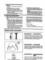
The rapidly moving line causes objects to be th_nvn
violently. The shield will not provide complete protection
the operatoror others. The operator must wear a safety face shield or goggles. Always wear heavy, long pants
and boot_. Keep others at least-30 feet away.
,
iii
ZONE
'_,W_G
L
-- HAz,u_/,ONE
This tool will throw objects and cut. Keep others including children, animals, bystanders, and helpers at least
30 feet away from the operator and tool Stop the eng_
_if you are approached.
&WARNING -- ntatugg
Trimmer Head
#71-85805
Use Only Gemfine Ret_acement
Trimmer head parts that are chipped, Cracked, broken, ot
damaged in any other way can fly apart and cause serious
injury. Do not use. Throw damaged _._
damaged parts before usir_ the tool.
away. Replace
I_I I±I
iiiiii
_O,
i
lllllllWllll
iii
II
I
i i
...........................
Illll
•
-
II
IIIIIllll
MI"I"IIO_
Aw_J
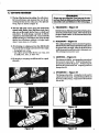
The tip of the line does the cutting. You will achi_
the best performance and minimum line wear by not
cr(r,vding the line into the cutting area. The fight and
:wrong ways are shown in Figure 15+
• The line will easily remove grass and weeds from
,,me,
he,,d.
_or
ddxk am _,N'bcI{h,n,,mn{,,,Io
e_s and _¢t and cause bbdness or _a" sariom in_kwy.
around wai_ fences, trees, and flower beds, butit
also can cut the tender bark of trees or shrubs and
sctwfences. To avoid damage, especially to delicate
vegetation or tre_ with tender bark. use less than full
thr_e and keep a 3 inch distance away. Keep in mind
that the line "_11 advance suddenly to a longer length
when it wears down to 4-5 inches.
z. sca&en
3.
¢kanjob.
-. pn.e
x7
The scalping U_chnique _move s unwanted vegetation.
Hold the bottmnff_trimmcr
head alx_3 inches alx_
the grouml and at an angle. Allow the tip of the line to
strike the ground around trees, p6sts, monuments, etc.- "
This technique increases line wear.
+: duringlight dutycutting,
+
-- near objects around which the line can wrap, such
as small posts, trees, or fence wire.
use full throttle for a good
x6
Hold the_
of the trimmer head alxaa3 inches alx_
above the grmmd and at an angle. Allow only thetip of
the line to ma_ contact. Do not fo_ the trimmer line
into the work area.
•o For bfmmingor
scalping use less than full throttle
to' prevent line breakage and _cessive line usage:
€ For mowing orsweeping,
-
I.
MOWING
-- Figure
18
Your trimm_is idcallbr ra_
in placesconveational
lawn mowers cannot re,ach. In the mowing position,
keep the line parallel to the ground. Avoid pressing the
head into the ground as this can scalp the ground and
damage the tool+
4. SWEEPING--Figure19
The fanning action of the rotatingline can be used.for
aquick and easy clean up. Keeptheline parallel to and
above the surfaces being swept andmovetimtoolfrom
• side to side.
+
lglgm. X6
Figure
17
Flglm¢
la
Figure
19
t
•
:_.
:
ii
i
.....
iiiiiii
Jl
,,i i
........................
i,
i
"
:.:..-
• For prolm'line feed:
--Use only genuine Sears pre-wound spools and
.080" diameter Sears Laser Line. Use of other
types of spools or lines can result in excessive
breakage, line v¢elding and improper line feed.
-- Ire-wound spools offer the most convenient
method for replacing line as well as optimum per-
formance.
• Always dean dirt and debris from thespool and hub
when performing any type maintenanc€.
Llns_g
New
Spool with
L_e
tngure2o
a.. Hold theTdmn_rHead asshowninFigure 19.Piess
the Lock Tab and turn Cov_j counterclockwise.
• b. Remove the Cover and Spool. Figure 21.
c.
Cleandirtand debris from all part_
d. 1ns'_an_r_nmmerncadpamfordamme_
Rephce".
XHmmer
head
parts
that are chipped,
cracked,
]
broken, or damaged in any Other way can fly apart ]
and cause seriousA w_mmNG
fin]my. Do not use. Replace[
damagedparts beforeusingthe tool.
J
e. Insert about 6 inches of Lind fromthe inside of the
l-Iubtlucagh the LineExitHoletbtheoutside to ia_
the Line from backing into the head. Figure 22.
]t_gur¢
_
1".Roatethe Line behindthe Balancing Pin (Figure 22)
while care_lly placing the Spool in the Hub.
g. pull on the Line extending outsidethe Hub to make
sure the Line will not advance. See Inset, Figm_22.
This iadica_..s that the :Line_*routexipropedy.
h. Re_
Cower:
1.) Align the fourcatches on the Hub with the cut_ats ia the Cover. Figai¢ 21..
2.) Pt_,s the Cover onto the Hub.
.....
.._
3.) "lhm Cover clockwise. Figure 20.
L °_k
to make sure all four Calches and the Lock
l_gure
Tab are properly fastened as shown in Figure 23, th_
_
.test_ Coverbytrig totaraitcouate_cl_kwise.
j. _0n
theLineagainfromo_sidetheHub.
IftheLine
canbepu!led fiomthe assembledhead, itisnot_
r_,:_ a,-,o,and"&eB_i_g
I_ and vddl f_d cow
tinuously when the Trimmer Head turns. Rem-ove
Cover and r_-route Line as shown in Figure 22.
I AUrouraachesmust
betastmed_mdthe_cktabtatched
[ eatotheconr. If insta_ tm_,
thecovercanny
![ _az_d
: b_a_e,, danm_
AwL-mls_.
a.o
]
IDC_ TAB
Fligure
_
o
i
:z.tmtamng Laneon the +_
a. voliow"_
_oot w/Line/'steps"a-d" and
• De_snot
advance,
orbreats_:_e _
-. tmpt+_>erly
routedinhead.
remove any Line remaining on the Spool.
b. Use a 40 foot length of .080 + Sears Laser Line.
- ._y
- L_'_o._.
c, Inert 1/16_to 1/8" of the end of u_eLine through one
of the holes in the rim of the Spool. Allow no more
•
-- Too li.le line outside head.
than 1/8 + Line to extend beyond the rim to avoid
interferenee with line ml_tse action. Figure 24.
• Welds onto spool.
--Line size ine_xrect.
d. W'mdthe Line onto lhe Spool in the dkection shown
by the-re'tow on the Spool and as lightly and evenly as
poss_le so theLinewiI! feed properly. Figure24.
tCAUTlON:'_Trimmer
_una on_spool
-
-- Incorrect spool.
Head will nol_
o. I_leases
pcup_iy tra_espo_ is t'dledbeyondtl_ notches
eontlnuously+
-- Woundbeyond .no_h..eson spool,
•atotmd theoutslde
edgeoftl__.
Improperly pauted in head.
Line size incorrecL ":: -- Shield !nstalled imp_periy.
""
e. :'Eollow "Installing Spool w/Line" steps "e-j."
* Usage is-excessive
--.
Imp ropedy..routed
in head.-- Line sizeincorrect.
-- Crowding _
"
W_CaLg_EON STOOL "
.-
,
against material being cut.-"
_ Pulls back into head
-- Too little Iine outside of head.
AS SHOWN i_" _,0"6_
•
+ Figure24
.........
.
'
_
1. l_dntain
......
" ..........
the tool according
to rec_nmended
•
pro-
-
2. Never Start the engine with the dutch shroud
removed. The dutch can fly apart and cause serious
the spark
',_motn_t_u_
m,_rJ
plug before
f*'_r mr-bit
r_trd-
_+
performing
_id it_-4"m_n_
do not use the Ot_ionaishould(r
".
w'_
idle_See"Carbu_orAdjustm_ts:"
Sears _
Line. Never
8. Re_place trimmer head parts
chipped, br°ken, or dam_
:'b_ore
_
that are cr_'.ked,
in any°ther
way
the_. " "....
-
d-'_'_' =_+'_.._.-_
cairburetor
..?:-
K:"AIIt _-.
IIIII III
....
. .^_.. -. /.-.7 ....
::....-.:
.__
v. use en_ genmne rel_acemem
.parts as re,_nv
:_.-.,,,_+_'bySear_
.....
.-.
:...
:.....
........
for sui_o rt- _ -
5. Keep others away when making
+
u_ wire, rope, string, etc.
7..-_+_'
-+'r_-.-.
:-_
_'_"............
•........
_1 .
.
.
7. Use duly .080" diameter
_.:___adjUs'_nentswititthed_
, _!__tl_nk_Hr___=_::_.,,.-_,_;_._g_,0b:ect;H01dtl_t6oP;Vith-,_._r_hand.
t._,_._-_t*ss
6 +a_,,].
. .........
6. Be sure trimmer head stops turning when engine
€_lures.Keep the trimmer line at the pfopex length.
3. Dis_nnect
+
:+
• +'-
IO._eatiretaoLRepla_da_pa_,Checkftx
fuelleaks.
Mak_ sure all fasteoers are m place-and
.
+.
Adiny air filter d_rea.ses the lifeand per ft_rman_ tffthe
e_g.!he and increases fuelco.sump_ion.
_theAk
F'_
_ys
afterStanksofrud
or _rsoro_J_n,+
• whklwver is less.
E_" Stot (Figu_26)is
r
More frequently
L _
enough
ingtheengineandcausingengine0an_,e.
on the Air Fdu_r Cov_r
to remove the Cover from the Engine.
F_gur_25.
2. Remove the Air Filter from_he Cover. Figure26+
3, Wash Filter in soap ar_ water.
4. SqueezeFilter dry and replace in Cover.
th_Cho_,: Lever..
theeorne_ofthecovertoheepdustfromenter-
in dusty conditions.
the two Sc_s
plaoMover
/
[_MYI'ION:] Do nol clean the air Fdter in gasoline
m,,
--
i,
,,
ii
=
iiii
,,,,
i
i
,,,,,,,,
i v
i
i
i
i
iiim
I
i
•
C_ _KOPE
L "-"
Ne_r _
•
thc eng_
c_dl _.UJO _
_
_'_ _
and_se
shm_
re_
The
serious _'y.
I
Aw_o
Do net remove the retahCmg tab and screw to remo_
_rs. _ _rlng beimth
thep,meyisanderte,,_o,,
and can lly outcausiagse_ous injury. If any part e_the
p_m_hou_ass_b___
other
t_.. _rope,
?d_ notusethe tool. Takeit toyour SearsService Center.
L Disconnect Spark Plug Wire. Figure 27.
2. Remove the Scww andHut_in_ the Throttle Trigger
Housing as shown in F'gure2. Hold theThrotfleTrigger
•away from Drive ShriftHousing and remove Throttle
Cable from Trigger. Pull Cable Out of Foam Grip =
_tunnel.- .......
3: Remove the four Cltitch Shroud Screws as shown in
Figure 27 with the small hex wrench provided.
4.
_"para_theClutchShroudfromtheEng_.
"A
Figure2K
ccm¢
Figure-2S
Use only a hand tool W remove the clutch. Do not use any
qpe of mo_d
_t or ar_ the dntch ln any way. Otherwise, the dutch will fly apart andcausesedous
injury.
5. Hold the "Hats" of the Clutch (Figure 28) with an
adjustable wrench as Shown in Figure 29 (inset) and
remove the Nut.counterc!ockwise
with a 3/8" socket
wrench.
NOTE: Clutch will slide off_eczankshaft
not.disassemble Clutch.
intact. Do
6: Remove the BeveiedWasher, Cluteh,:md Large Flat
Washer as shown in Figure29."
:
_::=__
the Pulley Housing from tl_ Engi_
8. Remove Rope R_ntion
Figure 29.
Screw. Remove any _nain-
ing rope.
9. Hold PuUey Housing anglhand turn ihe:pulley cloekwise_. _ as it will go. Then, turn the Pulley counterclockwi_ untilthe Pulley blotch is aligned with the
H:_g
Notch_ n_ to _e Retaining Tab and Screw.
_gttre 30. Next, tam the PUlley one complete turn
,
-_c6nnterclockwi_€ untilthe notches are aligned again.
10. Insert the sm_l hex wrenchlin_thehole
formed by
the Notches to hold the Pulley it_ position. Figure 30
0nse0.
11, U_ a42 '_length of replacement Rope.
12:, Move away 10 feet (3 meters) from the fueltank with
•the replacement Rope. 13se a match and melt both ends
nfth_
Ror'_Ao
r_r_v_n!
fravln¢,_
F.ttur_z9
" hot to obtain smcx_h, Pohaed ends.
the l_pe iS slill
14. Ins_ one _I of the Rope throu_
the Handle and
sccu.,€ with a imot.
_. tmcmt_ o(_ €od_d_ Ror)€_
tl_RO_ Exit
Hole, intothe'msideoftheHousi_,
intothePulley,
and up through the Pulley Hole. See Inset, Figure 30.
16. Wrap ROpe counterclockwise
around the Pulley
Ratchet and tuck loose end under Ropewhere it comes
out of the Pulley Hole. Leave a l-inch tail laying flat
on top of the Pulley between the Retainer Rj'b and the
rope Retention Screw/Post. Figure 30.
17. Reinstall the Rope Retention Screw into the reten_
fion post. Tightenuntil snug.
NOTE: Do not overtighten the Screw. Overtightening _ screw can cause the threads in the scow post
to strip out.
"18, Hold Rope taut at Rope Exit Hole so it will not move
and remove hex wrench.
CIRCLE
19 Slo_vly feed rope into the Pulley Housing.
20. Make sure Spacer is in place as shownin Figure 29,
then re_r_ steps to re-assemble.
|!OUS!N(;
NOTCH
..... the nut just until the beveled _her
is flattened
against the dutch. Over or under tightening the nut
_:
" damage.
cancause e ngme
n. m. xn)t
_l ..................
• Lubricate
v rw
,,11HII I
sn -r
uJBnacA oN
|
II
,,
,
iiiii
iiii
ii
i
iiiiii
the Flexible Drive Shaft:
-- After each ten (10) hours ofoperation.
•
,,,,
IIl,II
Before operating if the unit has been stored
90 days or longer.
• Use Flex Shaft
for
Lube Part No. 530-030102.
NOTE: A tube of'Flex Shaft Imbe" has been supplied
with your unit to be used after the first 10 hours of
operation.
....• Use the following
p_rocedure for bes_Jresults:
flex. A hot muffler can cause serious burns..
[€_rrloN:l
Lay the _
drive slmtton adeansurAvoid hying the shaft on the floor, ground,oron
any sui-face that may have dirt or debris. Even after
•:wiping the shaft, grease residue can pick up dirt particks that can cause damage or l)_nmture failur_
Take care to avoid injuring your hands
and fingers with broken wires when checking for
damage or wiping the flexible drive shaft. A cloth will
not prevent the broken wires from pun_turlng or tearing your skin.
i. Remove the Screw and Nut in the Throttle Trigger
Housing as shown in Figure 2.
2. Hold the Trigger away from the Drive Shaft Housing and_
rerm_vc the barrel end of the Cable from the Trigger as
shown in Figure 3.
!¢Ao'noN:J
4. Loosen
remove
Shrou&
5. Remove
Donot bendthecable;,
_
,, _
(but do not_)
the Hex Screws and
the Drive Sha_ Housing from the Clutch
Ngure I.
the Flexible Drive Shaft from the .Drive
Shaft Housing as shown in Figure 3I.
6. Check the Flexible DriveShaft for broken wires,twists,
or kinks and replace if damage is fiydnd.
7. Using a clean cloth, wipe the surface of the Flexible
Drive Shaft thoroughly to remove any old grease.
F_igu_32.
,..
....... .:-2._j-.
8. Apply a uniform coat ofhbe to the entire su trace ofth
Flexible Drive Shaft.
e
9. Inject the_remainingcontents
0fthe tube into thetopo f
the Drive Shaft Housing.
10. Replace Flexible Drive Shaft in the Drive Shaft
Housing.
U" Follow the instructions in "Assembly" to reinstall the
Throttle Cable and the Drive Shaft Housing.
Figure 3x
Figure3z
iii
'
CARBI_.E'roR
AD]U_
• This is a complicated task and it is important
i'ollow instructions in sequence as indicated.
to
AWAm mG
Make carburetor
adj_-_nents
with the drive shaft
housing supported to prevent the trimmer line from
contacting any object. Hold the tool with your hand;
do not use the optional shoulde_ strap for support.
away
when
making
carburetor
AWXV.mNG
Serious injurY !o the operator and otherscan (z'cur if the
carburetor is not properly adjusled.
.......
• Poor engine performance can be a result of other ............
causes such as dirty air filter, carbon build-up
on muffler outlets, etc. See "Trouble
Shooting
Chart"
before
proceeding
with carburetor
adjustments.
The carburetor has been carefiflly adjusted at the
factory. However, the operator must be sure that
adjustments are made when •any of the conditions
occur as mentioned in "Trouble Shooting Suggestions" below.
o
o
Very small adjustments
can affect engine performance/It
is important to turn the screw a very small
amount pe.r adjustment and test performance before
making further adjustments. Each adjustment should
be no more than the width of the slot in the adjusting
SCreWS.
L TROUBLE
SHOOTING
NOTE: In most cases, your engine can be made torun
properly with minor carburetor adjustments. Refer to
"Trouble Shooting Suggestions" for the _ndition you
areexperiencing and follow the instructions. Thebasie
carburetor settings are provided in case they are
_quired.
a. Turn the Low Speed Mixture Screw and-the High
Mixture Screw (Figme 33) clockwise until they
stop. Do not turn the screws until they are tight as
damage to the needle seats can occur.
_WARNING
Keep others
adjustments.
2.aASlC CARaURETORsE'rrmGs
SUGGE_rIONS
b. Turn the Low Speed Mixture and High Speed MixtureScrews one full turn counterclockwise.
c. Follow instructions "a. Preparation;" through "'f.
High Speed Mixture Adjustment"
3. PR04_DURE
a. PREPARATION
I..)Use a fr_h fuel mix. See "Fueling Your Engkn.e7
2. )Make sure the line extends to the length allowed
by the line limiter to provide correct load on
engine.
3.) Start the engine. Cut grass for 3 minutes towarm
engine. The engine musr be at operating temperature before carburetor adjustments ean be performed correaI2_
4.) Stop engine and remove air filter by pulling it out
with your fingers. Refer to "'Specifications'_ for
location.
-- Engine will not continue to run _t idle posRion.
• I_iDLESeEED_AP_F_)_STMEN_T
:
Speed Mixture Adjtts4ment."
l.)AUow engine to idle.
_- Trimmer Head continues to spin when the engine
idles, See "b. Idle Speed Adjustment" and "d.
Deceleration
Check:
•
2.)Adjust Idle Speed Screw (Figur_ 33) uatil the
engine continues to nat without stalling and
without the trimmer head moving.
• "
Engine dies or hesltateswhen itsimuld accelerate.
See "c. Acceleration Check"
-- Turn screw c_e
tq increase engine speed
if the engine stalls or dies."
-- loss ofcutting power whichcannot be corrected
by cleaning the air f'dter. See "f. High Speed Mixture Adjustmenl7
-- Turn screw cotintercloch_e
to slow engine
down and/or to keep trimmer head from
-- Engine does not return to idle from full throttle
within 2 seconds. See "d. Deceleration Check:'
--•Engine
will not run. See "Trouble
Shooting
Chart :' Then, if the carburetor requires adjustment, begin with"2. Basic Carburetor
Settings."
I The trimmer
] .p_x_ure.
line will be spinning during mostof
Wear your protective equilanent
this
and observe
3.)Follow instructions in "c. Acceleration
and "d. Deceleration Check:"
Check"
4.)No further adjustments
are necessary if the
trimmer head does not lurnat idle speed and
if performance is satisfactory.
after each adjtistment. The trimmei [
I Recheckidlespeed
AwARs
o
1I
head must not turn at !dlespeed to avoid seriousinjury
€, _TION
CHECK
e. LOW SP_
M_rrol_
l.)Allow engine to idle.
l.)Allow engine to idle.
2.)Squeeze Trigger fully
a. lr is ,lnoceed
to"d.
Deceleration Ch_k:'
b. lfthe engine does not accelerate smoothly,
mm the Low Speed Mixture Screw (Figure 33)
counterclockwise a small amount (no more
than the width of the slot in the adjusting
screw).
3.)Repeat step"2.)"until smooth acceleration is
obtained.
NOTE: It may be necessary to repeat '%. Idle
•Speed Adjustment, through "co Acceleration
Check" to obtain correct adjustments.
4.)Follow instructions in "d. Deceleration Check:'
d.DECELERATION.CHECK
l.)Aliow engine to idle, then squeege Throttle Trigger fully.
2.)Allow engine 1o run at-full speed for about 1
. -second.
3.)Release the Throttle Trigger to the idle position
and listen to the deceleration of the engine. It must
return to idle smoothly and within ! to2 seconds.
a. If performance is satisfactory, proceed to
:step "4.)"
b. If the engine slowly or erratlcally ret urv_ to
idle or idles erratically, repeat "b. Idle Speed
Adjustment" or continue through Low Speed
Mixture and High Speed Mixture Adjustments
to obtain proper deceleration.
4. )Recheck idle speed.
ADJUSTMENT
2.) _m the Low Speed Mixture Screw (Figure 33)
slowly clockwise until the speed starts to drop.
Note this position.
3.)3Mrn the Low Speed Mixture Screw counter-
clockwiseunt_ thespeedincreasesandthensiam
to drop again. Note this position.
4.)Set the Low Speed Mixture Screw at the midpoint between the two positions.
5.)Follow isntructioas in "c. Acceleration Check"
and "d. Deceleration Check:'
f. HIGH SPEED MIXTURE
[€.AwIrlON:IDo
_.DJIJ_
not operate
engine at full
chromeforprobngedperiodsWhaemaki.gmgh
speed adjustments
as damage
to the engine
OCCUlt',
l.)Support the drive shaft housing so the trimmer
line is offthe ground and will not make contact
with any object.
2. )Allow engine to idle, then sqneezeThrottle Trig:ger fully.
NOTE: Perform steps "'3.)" through "5,):"
at full throttle.
3.) Turn High Speed Mixture Screw (Figure 33) very
slowly clockwise until engine speed is reduced.
4.)'ibm High Speed Mixture Screw very slowly
counterclockwise. Stop when the engine begins
to run roughly.
5.)'Dam the screw slowly the minimum amount
clockwise until the engine runs smoothly.
6.)Followinstructions
in "c. Accderation Check"
and "d. Deceleration Check:"
!f the en_ne
accoralng
tOthese
does.not
ope_'_ate
aner
repea
.the
adjustingsteps,
do notusethetool.
Take
it to your Sears Service Center.
g. RFANSTALL AIR FILTF_
Be stay filter
is clean.See
'gdrFdter"
.... Maintenance
Section for inar._
in the
." "
i 6 i:i
r,ta r gto orthe
• ngtokeepd ra
rt aeaterlng e
ea
causlng
COVER
lglgu_3_11
i
,i
i
ii .
--
,;,,:;, ,
;,2,,,,,
,',
" .............
"7" :,",
......... ;.,
"' =,,"
Ig.S'rORAGE
3. Store tool and fuel in an area where fuel vapors cannot
•L Allow the engine t9 cool, empty the fuel system, and
-.
.
-:..
- reach sparks or open flames from waterheaters, electric
secure the tool before transporting or storing.
motors or switches, furnaces, etc.
2. EmtXy tbefuel systembeforestoringthetool.
Useupfuel
'4.
Store tbe tool so the line limiter cannot aecidentally cause
left inthe fuel lines and carburetor b'ystmtingthe engine
inju_. The tool can be hung by,the drive shaft
houfit_g.
and letting it run until it stops_
$. StO_tool out of teach,children
......
NOTE: If you do not want to renxwe the gasoline
'fromyourunit, SEARS CRAFISM#3q FuelStabilizer
(#71-33500) may be added to gasoline left in the tar&
Ittsimportanttopreventgum deposits
from formto minimize gum deposits and acids. If the tankis almost
,Lqgin essential fuel system parts such as the carbuempty, mix stabilizer with fresh gasoiinein a sdpamte
retor, fuel filter, fuel hose, or fuel tank during
container and add to the tank.
storage. Experience indicates that alcohol blended
ALWAYS FOLLOW
INSTRUCTIONS
ON THE
Mels (called Gasohol or using ethanol or methanol)
STABILIZER
CONTAINER.
THEN,
RUN THE
can attract moisture which leads to separation and
ENGINE
AT LEAST. I0 MINUTES
AFTER
formation of acids during storage. Acidic ga_qc_n:
STABILIZER [gADDED TO ALLOW MIXTURETO
____a_a_ethe fuel s_em of an engine while in storage.
• REACH CARBURETOR. S/ORE UNIT IN A SAFE
I.
AWA NG
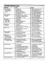
F. _X-itOuiIILlg $itiOOa_iLtqG (a-iART
.........
°.....................
SXTVlVIOM
CAUSE
Englne wUtnotstart
L Fuel tank empty.
2. Engine flooded.
3. Spark plug not firing.
4, Fuel not reaching carburetor.
5. Carburetor requires adjustment.
6. None oftheabove.
I. Fill tank with correct
fuel mixture.
2. See "'StartingIns_ctions:'
3. Install new plug/check ignition system.
4. Clean furl falter;inspectfuelline.
5. See '-cadmretor Adjustments:'
6, Contact_r SearsSeav_ Center.
I. Idle speed set too fast or too slow.
1. See "-cadmretor Adjusanents:'
2. See Ca_uretorAdjustmen_
3. Loosen screw to free trigger.
or w'dl run only for
a few seconds after
starting
•
_.-.--__
Engine will not idle
properly
low speed mixturerequires adj_t.
3. Throttle trigger scow too tight.
4. None of the above.
.
4. Contact your Sears Sen, ice Center.
..,.,
Engi_ win not
1. Air filterdirty.
2. Spark plug f_uled.
3. Carburetor reqnires adjustment.
4. Muffler outlets plugged.
5. None of the ab<rce.
acoelerate, lacks
power, or di_
under a load
Engine smokes
excessively
1. Air filterdirty.
2. Fuel mixture incorrect.
3. High speed mixture requires adjustment.
Engine runs hot
1.
2.
3.
4.
Trimmer head turks
at idte speed
l,
Carburetor requires adjustment.
2. Throttle trigger screw too tight.
Clutch requires repair.
Tr'dnmer head
stops under a loador
does not turn when
engin_ is acce.lerated
1. Drive shaft broken or not engaged.
2. Carburetor requires adjustments.
3. Clutch requires repair.
,,,,,,,,,,
,
, ,
,,
Linedoesnotad_
-
-.
,,,,,, ,,,,,,, ,,,,,,,,,,,,,,,,,,,,
Line releases continuously
.U
1. Clean or replace air filter.
2. Refuel with correct fuel mixture.
1. See "'Fueling "fourUnit."
2. See *'CarburetorAdjustments.'"
3. Replace with correct plug.
4. Contact your Sea_ Service Center.
1. See "'Carburetor Adjustments:'
2- Loosen screw to free trigger.
3. Contact your Sears Service Cehter.
1. Replace or see '_ssenably:"
2. See "'Carburetor Adjustments:
_
3. Contact your Sears Service Center._
,
1. Line size _t.
Line welds oa spool
Clean or replaceair filter.
Clean or replace spark plug and legal).
See ''Carburetor Adjastmems:'
Contact your Sears Service Center.
Cgntact your _
Service Center.
3. See "'CarburetorAdjustments:"
Fuel mixture incorrect.
"High speed mixture set too low (lean).
Spark plug incorrect.
None of the above.
L Line improperly routed in head.
2. Line improperly wound onto spool: :, _
3. Line size incorrect.
_;i..
4. Too little line outside head.
or
1.
2.
3.
4.
5;
2. ,Rewind line tightly madevenly:
3. Osebnly.080'SearsLaserLi_
®.
4. Remove cover. Pull6" oflmetooutside.
2. lnco_
stx_l.
3. Crowding line against material being cut,
1. Use only ,080" Sears Laser Hne ®.
2. Use proper spool.
3. Cut with tip of line.
4.cutang
at
4. R ,cec g m.
.....
"1. Line vamnd beyond notches on spool,
2. Line improperly routedin h&ad.
3.Line size incorrect,
I. Rewind linefightly and evenly.
2. Remove cover. Check line routing.
3. Oseoniy.0_O_I_erLine
®.
4. Shield installed improperly." t
4. Reinstall shield properly.
Line usage is excessive
1. Line improperly routed hahead.
2. Line size incorrect.
3: CuRing at high s_
around hard objects.
4. Crowding line agains_ material being cut.
Line pulls back into head
1. Too little line outside ofhead
1. Remove cover. Check line routing.
2, Use ordy D80" Sears Laser Line®.
3. Reduce speedaround hard objects.
4. Cut with tip of line.
L Remove cover. Pull6" ofline to outside.
_
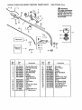
WEEDWACKER®
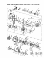
REPAIR
PARTS
LIST -
358.797!50-32cc
WARNING
All repairs, adjustments
and maintenance
not described ha the Operator's
Manual
must be performedbyqualffied
service personnel
29
3
17_@
-- 15
19--_
i
,,,,,,,,
20
14
Part
lqo.
Key
No.
5-30-027-549
530-4)94641:,
ffrD54!O_
530-0109g_
_O-O'_T_xgS
530-015785
530-O6928O
9
!0
11
12
IS
14
16
:
STD511005
530-4_.,4570
8TD541410
530-094551
530-094543
530-092243
7_5805
Descriptipn
Throttle Cable Ass'y.
+Drive Shaft Housing
Loeknut " •....
Anti-V/be Hafidle
+:
.Drive _katt _rip
Lod_ut
Part
Key
17
18 +
19
_0 :
21
.22
23
Description
5:_04592
Hub Ass'),.
71--85815
530-094494.
Spool w/Line
Cover
B_mrkst:=
Shaft Lubrication
Nut
952=030139
- 530-015768
530-015774
_4
Screw
sa0-oiogs9
(Incl. 9,10, & 11)
Screw
Line Limiter
25
26
27
Nut
28
530-067911
530-015775
530-031111
530-031098
530--027598
530-029159
530-027600
ThrottleLever Ass'y.
Operator'sManual
Screw
Hex Wrench (5/32)
Hex Wrench (3/16),[-.+
Anti-VibeDecal
'
ShaftWarning Decal
Shield Decal
Shieldmt _'y.
Flem'ble Drive Shaft
"
Dust Cup
Screw
CuttingHead Ass'y. +
_-r" Handle Ass'y.
29
80 i
31
+
I
I
\
\
\
\
\
SEARS
Key
No.
WEEDWACKER®
530-015768
530-039136
530-347987
530-027517
5:30-069291
_
55
56
57
58
.530-029395
530-027569
530-010961
530-094189
Locknut
,
Flywheel Ass y.
Washer
Fan Housing
Starter Pulley Kit
(Ind.//92)
Starter Spring
Starter Handle
Pulley Housing Ass'v.
Clutch Washer
"
Carburetor"
1 Carburetor G_ket
,Fuel Cap Assy.
,
Shroud & Tank Ass y.
(Ind. #9,10 & 13)
t Crankcase/Shroud
Gasket
Reed
Reed Stop
59
60
61
62
63
64
65
66
530-069254
530-010964
530--015767
530-027511
530-015770
530-015769
530-015496
530-015788
Clutch Ass'y. Kit
Clutch Housing
Screw
Spacer
Screw
. Screw
Screw
. "
Spacer
53O-O10960
'530-015789
_530-0t09M
5304)15126
530--015772
53O-015780
530-027546
530-027547
530-015771
5.30-014016
!
530-032103
530-015787
530-019158
530-032102
53O-069232
530-015777
530-0275-23
53O-O69257
[530-024903
!L
27527
530-039,34
530-015128
53O-012235
1 67
168
[ 69
[ 70
I 71
I 72
[ 73
[ 74
[ 75
I 76
[ 77
Screw -
]
Ass'y.0ncL
#
[
"
53o-o 77
Spa. r
Ignition Modde
Screw . ......
Cylinder
Spark Plug
]
530--015796
STD541137
I 530-035164
: 530-035166
530--035178
530-035106
530-035188
530-035031
530--035028
. 530--035014
530-035151
_._<,_
,.
[ ....
/
*+
] *+
] +
+
+
+
+
*+
*+
Washer
Nut
"
Pump Gasket
Pump Diaphragm.
"
Inlet Screen
Inlet Needle Valve
Metering Lever Spring
Metering Lever
Metering Pin
Metering Diaphragm
Metering Diaphragm
Gasket
"
+ Circuit Plate Gasket
Hi Speed Needle Spring
Hi Speed Needle
Idle Needle
Idle Needle Spring
Idh Speed Spring
Idle Speed., Screw
Curb. Kwlk Re] _ Kit
, ,.(÷ __di'c___t_G _t_nts)
530-035147
530--03_q335
530-035142
530--035141
530-035023
530-035208
530-035203
530-4)35260
r . ....
I sls5
[
[
[
]
I
]
l
|
|
!
Kit
Description
.
78
36-39)
] _
Kill Switch Ramp,
'
[ 80
Switch Spring Ass y.
[ 81
Screw
..
[ 82
P:_ton Pin Retainer
[ 83
Piston Ring
[ 84
t Cylinder G.asket
] 85
i Hston. Kit (Incl. #32,33,
• I ......
&pin)
.
._::__
86
Inner I_ean?g
......_°
Retaining Ring
87
Crankshaft Seal
Beanng Outer
88
Rope KR
89
Screw
90
Retainer
91
MufflerKit
92
Muffler Attachment Spring
,
i
i,
/
Crankcase/Crankshaft
Assy. (Inc1.#20,21:28)
Connecting Rod Ass y.
OncL Bearings)
Crankshaft Retaining Ring
Crankshaft Ass'),.
Flywheel Key
Screw
Screw
Kill Switch Insulator
Lead "Wire
Crankcase
530-027545
530-027543
S'IT)610603
53O--0i5162
53O-O25875
530-019178
530-069275
- 358.797150-32cc
50
51
52
53
54
Screw
Air Filter Cover
Air Filter
Screw
Spacer
Wave Washer
Choke Shutter
Air Filter Plate
Fuel Line Kit
Fuel Pick-upAss'y.
530-019154 530-027593
530-027594
.....530-014015
LIST
Part
No.
Description
5_15773
530-027529
53O-02753O
530-015849
53O-O27528
530-015254
5-3O-O27526
530-027527
530-069247
53O-O10897
530-O35259
530-019156
530-O10729
530-027606
!
PARTS
Key
No.
Part
No. ,
!
REPAIR
C rb.C ..keVrhphraga
530-069276
530-015239
530-015717
530-027781
952-701612
530-015823
Not Shown
_
530-029732
530-061274
530-014040
-
Kit (*Indicates Content.,
EngineGasket Kit
(t'Indieates Contents)
Screw
Screw
MufflerGuard
Spark ArrestorKit
Screw
•
':" "
Instruction
.
"
Decal
Carton
Ass'y. Parts Bag
)i
!
INDEX
ACC_RIES
....................................
ADJUSTMF_,NTS ..................................
Assist Handle .............................
Carburetor ....................................
Line Advance...
..............................
Module Air Gap ...............................
AIRSffk
Plug Gap ................................
LTE,R .......
. .........
...................
10
9
9
20
14
2
2
17
LUBRICATION
Engine ...............
.............
...........
U
......
Flexible Drive Shaft ............................
19
MAINTENANCE
Air Filter ..... : ...............................
17
• Carburetor .....................................
20
Flexible Drive Shaft, ............................
19
safety ........................................
I7
ASSEMBLY
Starter Rope ..................................
18
Assist Handle ... .............
.................
"..9
Trinm,,er Head ........................
. .......
16
Drive Shaft Housing.'. ; ...........................
7
Trouble Shooting Chart ..................
- ......
22
Prep, tion
.. ...... 7
MODULE AIR GAP ...............................
2
Shield ..................................
_..... 8
OIL, FaNGINE
Tlarottle Cable ..................................
8
Ratio to Gasoline ..............................
11
Trimmer Head .. ..................................
8 -- Types,to Use; not to Use .... _ ...;-.
: ............
11
AU'I_MAq['IC LINE FEED ........................
14
OPERATION
CARBURETOR AD2USTMEN'IS ...............
.... 20
Advancing theLine ..... .......................
14
CAKI_N CONIT_MI'S ...................
..........
6
Mowing ...._..................................
15
COLD ENGINE STaG
"
" . 12
Pre-Operation
Checks ..........................
12
CONTROLS ......................................
2
Position ... .....................................
9
_TING
METHODS ............................
15
Sfifety .... : ...................................
14
DRIVE SIIAFr HOUSING ASSEMBLY ...............7
Scalping ......................................
15
ENGINE
Starting the Engine .............................
12
Air Filter .....................................
17
Speed........................................
13
Carburetor ...
.20
StoppingthdEngine............................
13
Controls......................................
2
Sweeping ..............
.......................
15
Fuel Mixture..................................
11
Trimming .............................
-. - :... 15
Starter Pulley .................
.................
18
PARTS LIST .....................................
23
PRF_OPERAT1ON
CHECKS .......................
12
Starting Instructions .............
...............
I2
Storage.......................................
5
PREWOUND SPOOLS ............................
16
TroubleShooting..............................
22
QUICK REFERENCE
PAGEL ...........
: ..........
27
ENGINE OIL
REPAIR PARTS LIST ............................
23
Ratioto Gasoiine...........................
...ii
SAFETY INSTRUCTIONS, WARNINGS ......
_......
3
Types to Use; not to Use... : ....................
I1
SHIELD, ASSEMBLY ..............................
g
FILTER, AIR ....................................
17
SPARK PLUG GAP ...............................
2
FLEXIBLE DRIVE SHAFT LUBRICATION .........
19
SPARK ARRFS!V)R ........................
_._....6
FUEL
SPECIFICATIONS
................................
2
Gasoline/Oil Mixture ...........................
11
SPOOL
Installation ..................
_.................
16
Mixing Fuel ..............
; : : .................
11
Maintee_.an¢* _. : .......
; ....".
_.... :... ..........
16
Pouring Fu_uel.._ ........
_.........
=---_- ......
..11
Safety ......................
. :.-_ _. .........
Zi(=
Prewound.......................................
16
Storage .......................................
I1
Rewinding ....................................
17
GASOLINE
STARTER ROPE REPLACEMENT.- ................
18
Ratio to Oil ......................
: ............
11
STARTING INSTRUCTIONS
......................
12
Types to Use; not to Use ........................
II
STORAGE ..........
. ........................
:..-_
TItROTIqLE CABLE ASSEMBLY ....................
g
IDLE SPEED ADJUSTblENT.
.....................
20
-LINE
TRIMMER HEAD
Advance .............
: ....................
14. 22
Assembly .....................................
8
Breaking .... : .............................
13, 22
Line Routing.. :_... ,...: .......................
:16
Removal ......
:...= ...........................
g
Length to Cut as Replaeemen_ ................
_... 17
Maintenance ..................................
!6
Replacement .............
-..................
16 '
TROUBLE SHOOTING CHART ...................
22
R_ng
or_ Spool ............................
17
IWARM
ENGINE
STARTING
......................
12
Routing in Head .....
16
WARM
ENGINE STARTING AFTER RUNNING
Safety ........................................
14
OlYr OF FUEL
"
... t3
Size to Use ...................................
17
WARNINGS AND SAFETY INSTRUCTIONS ...... 3 & 5
Welding onto Spool. .........................
17, 22
WARRANTY ......................................
"2
Trouble Sh_'dng ................................
22
ii
i
QUICK REFERENCE
i
i
PAGE
Read and Follow All Warnings, Safety [_ns,
and Operat_g I_ns.
Failure to do so can result in serious injury.
Page No.
PREPARA'I_ON
....................
, ...............................
3 & 5
1. Know all warnings and safety instructions in this manual.
2. Wear safety face shield or goggles for eye protection.
3. Dress safely - boots or safety shoes and heavy, long pants.
4_ Checktool for wom_ loose, missing, or damaged parts; repair or replace as necessary
5. Inspect and ensure the area to be cut is safe.
6. Keep children, bystanders, and animals 30 feet (t0 meters) away.
before using thetool.
FUELING
1.
2.
3.
4.
5.
6.
Eliminate all sources of sparks or flame where fuel is mixed, poured, or stored.
Use 40 parts regular unleaded gasoline to I part air-cooled, 2-cycle engine oil.
Use clean and fresh fuel.
Mixand store fuel in an approved, marked container.
Mix and pour fuel in an outdoor area.
Move a minimum of 10 feet (3 meters) away. from the fuel and fueling site before starting engine.
STARTING
L
2.
3.
4.
11
THE ENGINE
..........................
. . . . ....
_. .....
. 12
Extend !ine 6 i_n_hes from Lhehead.
Rest the shield on the ground suppg._ing the trimmer head up offthe ground away from objects and on-lookers.
Keep throttle trigger squeezed fully until engine runs.
Pull the starter rope sharply and quickly.
OPERATING
THE TOOL
........................................
13
1. Do not operate the tool at a higher speed than necessary.
2. Release the throttle trigger and allow the engine to idle when not cutting.
3. Stop the engine by moving the ignition switch to the "Off" position.
o
1.
2.
3.
4.
•
o
_
Run fuel out of the unit before
Disconnect spark plug before
Clean air filter frequently but
Store in a dry place out of the
•
•
_
•
•
_
•
•
o
_
_
_
•
•
u
_
•
•
e
•
•
_
storing.
performing maintenance except for carburetor
always after 5 tanks of fuel.
reach of children.
o
•
t*
•
!
•
m
adjustments.
•
•
.D
•
•
•
•
_
•
•