1
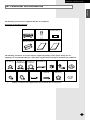
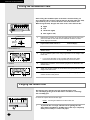
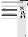
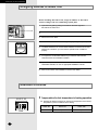
ENGLISH ESPAÑOL INSTALLATION MANUAL MANUAL DE LA INSTALACIÓN MANUEL D’INSTALLATION MANUALE INSTALLAZIONE MANUAL DE INSTALAÇÃO INSTALLATIONSHANDBUCH E°XEIPI¢IO E°KATA™TA™H™ DEUTSCH E§§HNIKA Free Joint Multi Air Conditioner (Cool and Heat) Acondicionador de aire libre del empalme multi (Refrigeración y Calefacción) Climatiseur Free Joint Multi (Refroidissement et Chauffage) Aria condizionata Free Joint Multi (Raffreddamento e Riscaldamento) Free Joint Multi ar condicionado (Refrigeração e Aquecimento) Free Joint Multi Klimaanlage (Kühlen und Wärmen) ¶ÔÏÏ·Ïfi ∫ÏÈÌ·ÙÈÛÙÈÎfi ªË¯¿ÓËÌ· ∂χıÂÚ˘ ŒÓˆÛ˘ (æ‡Í˘ - £¤ÚÌ·ÓÛ˘) PORTUGUÊS ITALIANO MH023FWEA MH026FWEA MH035FWEA MH052FWEA FRANÇAIS Indoor unit E S F I P D G DB98-24189A(1) Safety Precautions You should take the following safety precautions when using your air conditioner. WARNING INSTALLING THE AIR CONDITIONER • If you don’t follow the safety precautions, you may get the risk of an electric shock, injury or death. •The manufacturer or qualified service personnel must install this air conditioner. • Unplug the electric power before repairing, installing or cleaning. ◆ The unit should not be installed by the user. Ask the dealer or authorized company to install the units except room air conditioners for the U.S.A and Canada area. ◆ If the unit is installed improperly, water leakage, electric shock or fire may result. ◆ Mount with the lowest moving parts at least 2.5m above the floor or grade level. (If applicable) ◆ The manufacturer does not assume responsibility for accidents or injury caused by an incorrectly installed air conditioner. If you are unsure about installation, contact an installation specialist. ◆ When installing the built-in type air conditioner, keep all electrical cables such as the power cable and the connection cord in pipe, ducts, cable channels e.t.c to protect them against liquids, outside impacts and so on. POWER SUPPLY AND CIRCUIT BREAKER ◆ If the power cord of this air conditioner is damaged, it must be replaced by the manufacturer, its service agent or similarly qualified persons in order to avoid a hazard. ◆ The unit must be plugged into an independent circuit if applicable or connect the power cable to the auxiliary circuit breaker. An all pole disconnection from the power supply must be incorporated in the fixed wiring with a contact opening of >3mm. ◆ Do not use an extension cord with this product. ◆ If the unit is equipped with a power supply cord and a plug, the plug must be accessible after installation. ◆ The air conditioner must be installed in accordance with national wiring regulations and safety regulations wherever applicable. E-2 ENGLISH Contents ◆ PREPARING THE INSTALLATION ■ Deciding on Where to Install the Air Conditioner ........................................ ■ Air Conditioner and Accessories ................................................................. 4 7 ◆ INSTALLING THE AIR CONDITIONER ■ Fixing the Installation Plate ......................................................................... ■ Purging the Indoor Unit ............................................................................... ■ Connecting the Assembly Cable ................................................................. ■ Assigning Address to Indoor Unit ................................................................. ■ Additional Functions ..................................................................................... ■ Installing and Connecting the Drain Hose of the Indoor Unit ...................... ■ Changing Direction of the Drain Hose ......................................................... ■ Installing and Connecting the Assembly Pipe of the Indoor Unit ................ ■ Cutting or Extending the Pipe ..................................................................... 8 8 9 10 10 11 11 12 13 ◆ COMPLETING THE INSTALLATION ■ Fixing the Indoor Unit in Place .................................................................... ■ Wiring wired Remote Controller(Optional) .................................................. ■ Final Checks and Trial Operation ................................................................ ■ Providing Information for User .................................................................... ■ Troubleshooting ........................................................................................... 14 15 16 16 17 E-3 PREPARING THE INSTALLATION Deciding on Where to Install the Air Conditioner When deciding on the location of the air conditioner with the owner, the following restrictions must be taken into account. General Do NOT install the air conditioner in a location where it will come into contact with the following elements: ◆ Combustible gases ◆ Saline air ◆ Machine oil ◆ Sulphide gas ◆ Special environmental conditions If you must install the unit in such conditions, first consult your dealer. Indoor Unit ◆ There must be no obstacles near the air inlet and outlet. ◆ Install the indoor unit on a surface that can support its weight. ◆ Choose a position that enables the piping and cables to be easily connected to the outdoor unit and the recommended length of 7.5 metres to be respected. ◆ Leave enough clearance beneath the indoor unit to enable the filters to be removed without hindrance. ◆ Maintain sufficient clearance around the indoor unit, as indicated in the diagram on the page opposite. ◆ Make sure that the water dripping from the drain hose runs away correctly and safely. CAUTION ◆ You have just purchased a Free Joint Multi air conditioner and it has been installed by your installation specialist. ◆ This device must be installed according to the national electrical rules. ◆ Max input power & current is measured according to IEC standard and input power & current is measured according to ISO standard. ◆ More than 2 indoor units should be installed when you use Free Joint Multi air conditioner. E-4 ENGLISH PREPARING THE INSTALLATION ◆ MH040FXEA2/MH052FXEA2 ❊ The split type, 1-way cassette, slim duct type indoor units can be installed together. ◗ Piping outside diameter Indoor unit Outdoor unit Power supply Ø, V, Hz ✴✴ 023/026/035✴✴ MH040FXEA2 MH052FXEA2 1, 220-240, 50 Unit ✴✴ 023/026/035✴✴ Outside diameter Liquid Gas 1/4” 3/8” ❊ MH052FWEA indoor unit cannot be connected to the MH040FXEA2 and MH052FXEA2 outdoor units. ❊ MH040FXEA2 outdoor unit cannot be connected to the following indoor unit combination. ✴✴026✴✴ + ✴✴035✴✴ / ✴✴035✴✴ + ✴✴035✴✴ 200 mm or more 100 mm or more 160 mm or more (h) (H) 600 mm minimum A 300 mm minimum B 300 mm minimum 600 mm minimum Main power switch ◗ Piping length and the height Dimension Composition 1 Room max length 20 m A, B 2 Room total max Max height between length indoor unit & outdoor unit 40 m 15 m A+B (H) Max height between indoor units 7.5 m (h) E-5 PREPARING THE INSTALLATION Deciding on Where to Install the Air Conditioner (Continued) ◆ MH068FXEA4 / MH080FXEA4 ❊ The split type, 1-way cassette, duct type indoor units can be installed together. ◗ Piping outside diameter Indoor unit ✴✴023/026/035/052✴✴ Outdoor unit Power supply Ø, V, Hz MH068FXEA4 MH080FXEA4 1, 220-240, 50 Unit ✴✴023/026/035✴✴ ✴✴052✴✴ Outside diameter Liquid Gas 1/4” 3/8” 1/4” 1/2” 200 mm or more 100 mm or more 160 mm or more (h) (H) 600 mm minimum 300 mm minimum A B C D 300 mm minimum 600 mm minimum Main power switch ◗ Piping length and the height Dimension Composition E-6 1 Room max length 25 m A, B, C, D 2 Room total max 3 Room total max 4 Room total max Max height between length length length indoor unit & outdoor unit 30 m 45 m 70 m 15 m A+B A+B+C A+B+C+D (H) Max height between indoor units 7.5 m (h) PREPARING THE INSTALLATION ENGLISH Air Conditioner and Accessories The following accessories are supplied with the air conditioner. Accessories in the Indoor Unit Case Installation Plate (1) Remote Control Wired remote Controller cables (1) Batteries for Remote Control (1) Owner’s Instruction Installation Manual The following connection accessories may be supplied, depending on the option. If they are not supplied, it is recommended that you collect them together before starting to install the air conditioner. Assembly Piping, Ø6.35mm (1) Pipe Clamps A (3) ➢ Assembly Piping, Assembly Piping, PE T3 Foam Ø9.52mm (1) Ø12.70mm (1) Tube Insulation(1) (✴✴023/026/035✴✴) (✴✴052✴✴) Pipe Clamps B (3) Cement nail (6) Vinyl Tape (1) M4 x 16 Tapped Screws (6) Drain Plug (1) Drain Hose, length 2m (1) Rubber Leg (4) Putty 100g (1) If these accessories are supplied, they are located in the accessory box. E-7 INSTALLING THE AIR CONDITIONER Fixing the Installation Plate Before fixing the installation plate to the wall or window frame, you must determine the position of the 65-mm hole through which the cable, pipe and hose pass to connect the indoor unit to the outdoor unit. When facing the wall, the pipe and cable can be connected from the: ◆ Right ◆ Left ◆ Underside (right) ◆ Rear (right or left) 1 Determine the position of the pipe and drain hose hole as seen in the picture and drill the hole with an inner diameter of 65mm so that it slants slightly downwards. 2 If you fix the indoor unit to a... Follow step(s)... Wall 3. Window frame 4 to 6. 30mm Installation plate Pipe hole (Ø65mm) ✴✴023/026/035✴✴ (Unit : mm) 3 ➢ If you mount the plate on the concrete wall with anchor bolts, the anchor bolts must not be projected by more than 20mm. 14 97 156 ✴✴052✴✴ Fix the installation plate to the wall giving attention to the weight of the indoor unit. 4 Determine the positions of the wooden uprights to be attached to the window frame. 5 Attach the wooden uprights to the window frame giving attention to the weight of the indoor unit. 6 Attach the installation plate to the wooden uprights using tapping screws as seen in the picture. (Unit : mm) 26 190 134 Purging the Indoor Unit On delivery, there may be inert gas inside the indoor unit. You should purge the gas from the indoor unit before connecting the assembly pipe. Unscrew the caps at the end of each pipe. Result: All inert gas exhausts from the indoor unit. ➢ E-8 To prevent dirt or foreign substance from getting into the pipes during installation, do NOT remove the caps completely until you are ready to connect the pipes. INSTALLING THE AIR CONDITIONER ENGLISH Connecting the Assembly Cable The indoor unit is powered from the outdoor unit via the assembly cable. 1 Extend the assembly cable if necessary. 2 Open the front grille by pulling on the tabs on the lower right and left sides of the indoor unit. 3 Remove the screw securing the connector cover. 4 Pass the assembly cable through the rear of the indoor unit and connect the assembly cable such as figure. ➢ Each wire is labelled with the corresponding terminal number. 5 Pass the other end of the cable through the 65 mm hole in the wall. 6 Replace the connector cover, carefully tightening the screw. 7 Close the front grille. Indoor unit 1(L) 2(N) 1 8 For further details on how to plug the other end of the assembly cable into the outdoor unit, refer to installation manual of the outdoor unit. F1 2 E F2 F1 F2 Earth terminal Outdoor unit 1 2 E F1 F2 Earth terminal 1(L) 2(N) F1 F2 E-9 INSTALLING THE AIR CONDITIONER Assigning Address to Indoor Unit Before installing the indoor unit, assign an address to the indoor unit according to the air conditioning system plan. 1 Open the front grille by pulling on the tabs on the lower right and left sides of the indoor unit. 2 Remove the screw securing the cover PCB. 3 Remove the cover PCB. 4 The address of the indoor unit is assigned by adjusting MAIN(SW02). 5 The MAIN address is for communication between the indoor unit and the outdoor unit. Therefore, you must set it to operate the air conditioner properly. 6 It is required to set the RMC address if you install the wired remote controller and/or the centralized controller. 7 If you install optional accessories such as the wired remote controller, centralized controller, etc. see an appropriate installation manual. 8 Refer to the outdoor unit installation manual for the details. Cover PCB SW02 MAIN Additional Functions K5 K6 K7 K8 SW06 E-10 Compensation for lost temperature in heating operation ◆ Reduces the difference between an actual room temperature and a sensed temperature by the air conditioner when heating. Switch No. Switch ON Switch OFF K5 2°C compensation 5°C compensation INSTALLING THE AIR CONDITIONER ENGLISH Installing and Connecting the Drain Hose of the Indoor Unit When installing the drain hose for the indoor unit, you should check if condensate draining is adequate. When you pass the drain hose through the 65-mm hole drilled in the wall, check the following. 5 cm less The hose must NOT slant upwards. The end of the drain hose must NOT be placed under water. Do NOT bend the hose in different directions. Ditch Keep a clearance of at least 5cm between the end of the hose and the ground. Do NOT place the end of the drain hose in a hollow. To install the drain hose, do the following. 1 If necessary, connect the 2-meter extension drain hose to the drain hose. 2 If you use the extension drain hose, insulate the inside of the extension drain hose with a shield. 3 Shield Drain hose Extension drain hose Fit the drain hose into 1 of 2 drain hose holes, and then fix the end of the drain hose with a clamp tightly. ➢ If you don’t use the other drain hose hole, block it with a rubber stopper. 4 Pass the drain hose under the refrigerant pipe keeping the drain hose tight. 5 Pass the drain hose through the hole in the wall. Check if it slants downwards as seen in the picture. ➢ The hose will be fixed permanently into position after finishing the installation and the gas leak test; refer to installation manual of the outdoor unit for further details. Changing Direction of the Drain Hose You can select the direction of the drain hose depending on the place you want to install the indoor unit. Screws hole 1 Detach the rubber cap with the flyer. 2 Detach the insulation(FOAM-PE). 3 Detach the drain hose by pulling it and turning to the left. 4 Insert the drain hose by fixing them into the groove of the drain hose and the outlet of the drain pan. 5 Insert the insulation(FOAM-PE) to prevent water leakage. 6 Stick the rubber cap with the screwdriver by turning it to the right until it fixes to the end of the groove. Screw Drain hose Drain pan outlet Rubber cap Insulation E-11 INSTALLING THE AIR CONDITIONER Installing and Connecting the Assembly Pipe of the Indoor Unit There are 2 refrigerant pipes of different diameters: ◆ The smaller one is for the liquid refrigerant ◆ The larger one is for the gas refrigerant A short pipe is already fitted to the air conditioner. You must extend the pipe using the assembly pipe. (Optional) The connection procedure for the refrigerant pipe varies according to the exit position of the pipe when facing the wall: ◆ Right (A) ◆ Left (B) ◆ Underside (C) B A ◆ Rear C 1 Cut out the appropriate knock-out piece on the rear of the indoor unit unless you connect the pipe directly from the rear. 2 Smooth the cut edges. 3 Remove the protection caps of the pipes and connect the assembly pipe to each pipe. Tighten the nuts first with your hands, and then with a torque wrench applying the following torque. Outer Diameter 6.35 mm 9.52 mm 12.70 mm Torque (kgf•cm) 140~170 250~280 380~420 ➢ If you want to shorten or extend pipes, refer to page 13. 4 Cut off the remaining foam insulation. 5 If necessary, bend the pipe round along the bottom of the indoor unit. Then pull it out through the appropriate hole. ◆ The pipe should not be projected from the rear of the indoor unit. ◆ The bending radius should be more than 100mm. E-12 6 Pass the pipe through the hole in the wall. 7 For further details on how to connect to the outdoor unit and purge the air, refer to installation manual of the outdoor unit. ➢ The pipe will be insulated and fixed permanently into position after finishing the installation and the gas leak test ; refer to installation manual of the outdoor unit. INSTALLING THE AIR CONDITIONER ENGLISH Cutting or Extending the Pipe 7.5 metres of piping is supplied with the air conditioner(Optional). This length can if necessary be: ◆ Extended to a maximum length ◆ Shortened as required ☛ If more than 7.5 metres of piping is required: ◆ The assembly cable must also be extended ◆ Refrigerant must be added to the circuit by an approved installer; otherwise, the indoor unit may freeze 1 Make sure that you have the required tools available (pipe cutter, reamer, flaring tool and pipe holder). 2 If you wish to shorten the piping, cut it using a pipe cutter, taking care to ensure that the cut edge remains at a 90° angle with the side of the pipe, and referring to the illustrations below for examples of edges cut correctly and incorrectly. Oblique Rough Burr 90 O O x x x 3 To prevent any gas from leaking out, remove all burrs at the cut end of the pipe, using a reamer. 4 Slide a flare nut on to the pipe and modify the flare. Outer Diameter(D) 6.35 mm 9.52 mm 12.70 mm 5 6 Check that the flaring is correct, referring to the illustrations below for examples of incorrect flaring. x x x x Inclined Damaged Surface Cracked Uneven Thickness Align the pipes to be connected and tighten the flare nuts first manually and then with a torque wrench, applying the following torque. Outer Diameter 6.35 mm 9.52 mm 12.70 mm 7 Depth(A) 1.3 mm 1.8 mm 2.0 mm Torque(kgf•cm) 140~170 250~280 380~420 For further details on how to connect up to the outdoor unit and purge the circuit, refer to installation manual of the outdoor unit. E-13 COMPLETING THE INSTALLATION Fixing the Indoor Unit in Place After checking for a gas leak in the system, you can insulate the pipe, hose and cables. Then place the indoor unit on the installation plate. 1 To avoid condensation problems, place heat-resistant polyethylene foam separately around each refrigerant pipe in the lower part of the indoor unit. 2 Wrap the refrigerant pipe and the drain hose in the rear of the indoor unit with the absorbent pad. ➢ Wind the pipe and hose three times to the end of the indoor unit with the absorbent pad. (20-mm interval) 3 Wind the pipe, assembly cable and drain hose with insulation tape. 4 Place the bundle (the pipe, assembly cable and drain hose) in the lower part of the indoor unit carefully so as not to be projected from the rear of the indoor unit. 5 Hook the indoor unit on the installation plate and move the unit to the right and left until it secures in place. 6 Wrap the rest of the pipe with vinyl tape. 7 Attach the pipe to the wall using clamps (Optional). Installation plate E-14 COMPLETING THE INSTALLATION ENGLISH Wiring Wired Remote Controller (Optional) Connect the power cable, which is connected with the outdoor unit and supplied by another source, making sure that the power cable terminal should not be changed. The F3 and F4 communication cable may be cross-connected, however, it is recommended that they are connected to the corresponding F3 and F4 terminal. Indoor unit PCB CN33 (Blue) Accessory in the indoor unit case CN32 (White) 1(L) 2(N) F1 F2 Indoor Unit Terminal Block Accessory in the remote controller F1 (F3) F2 (F4) V1 V2 Wired Remote Controller (Optional) K1 K2 K3 K4 Change DIP switch in the indoor unit PCB SW05 K1 : ON OFF E-15 COMPLETING THE INSTALLATION Final Checks and Trial Operation To complete the installation, perform the following checks and tests to ensure that the air conditioner operates correctly. 1 Check the following. ◆ ◆ ◆ ◆ ◆ ◆ ◆ 2 Strength of the installation site Tightness of pipe connection to detect a gas leak Electric wiring connections Heat-resistant insulation of the pipe Drainage Earth conductor connection Correct operation (follow the steps below) Press the button and check the following. ◆ The indicator on the indoor unit lights on. ◆ The airflow blade opens and the fan gears up for operation. 3 Press any button and check the following. ◆ The appropriate indicator lights on and the air conditioner operates according to the selected mode or function. 4 Press the button and check the following. ◆ The airflow blades work properly. Providing Information for User After finishing the installation of the air conditioner, you should explain the following to the user. Refer to appropriate pages in the User’s Manual. 1 How to start and stop the air conditioner 2 How to select the modes and functions 3 How to adjust the temperature and fan speed 4 How to adjust the airflow direction 5 How to set the timers 6 How to clean and replace the filters ➢ E-16 When you complete the installation successfully, hand over the User’s Manual and this Installation Manual to the user for storage in a handy and safe place. COMPLETING THE INSTALLATION ENGLISH Troubleshooting The error indicated on the display panel of indoor unit Display Explanation Remark Communication errors in the indoor unit Communication errors in the outdoor unit Indoor unit room temperature sensor error (Open/Short) Inlet pipe temperature sensor error in the indoor unit heat exchanger (Open/Short) Outlet pipe temperature sensor error in the indoor unit heat exchanger (Open/Short) Indoor unit heat exchanger in temperature sensor detached Indoor unit heat exchanger out temperature sensor detached Indoor unit heat exchanger in & out temperature sensor detached Indoor fan motor malfunction More than 2 indoor units cool and heat simultaneously EEPROM error EEPROM option setting error Communication cable and power cable misconnected The number of indoor unit mismatched Compressor discharge sensor error (Open/Short) Outdoor unit error E-17 THIS AIR CONDITIONER IS MANUFACTURED BY: ESTE AIRE ACONDICIONADO HA SIDO FABRICADO POR: CE CLIMATISEUR EST FABRIQUE PAR: QUESTO CONDIZIONATORE D’ARIA È PRODOTTO DA: ESTE APARELHO DE AR CONDICIONADO É FABRICADO POR: DIESE KLIMAANLAGE IST FABRIZIERT VON: AYTH H ™Y™KEYH KATA™KEYA™THKE A¶O : ELECTRONICS G-18 Printed in Korea