1
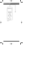
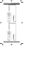
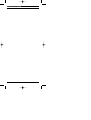
Primetest 200
PrimeTest 200
Operating Instructions
304A550 Rev 3
Bracken Hill, South West Industrial Estate,
Peterlee, Co. Durham SR8 2SW. England.
Tel: +44 (0)191-586 3511 Fax: +44 (0)191-586 0227
www.seaward.co.uk
[email protected]
[email protected]
Operating Instructions
Primetest 200
Operating Instructions
Primetest 200
Fig 3.
Fig 1.
Fig 2.
Fig 4.
Operating Instructions
Primetest 200
Operating Instructions
PrimeTest 200
Fig 5.
Fig 6.
Operating Instructions
PrimeTest 200
Operating Instructions
Fig 7.
Fig 8.
PrimeTest 200
Fig 9.
Fig 10.
Operating Instructions
PrimeTest 200
Fig 11
Operating Instructions
PrimeTest 200
Fig 12A.
Fig 12B.
Operating Instructions
PrimeTest 200
Operating Instructions
PrimeTest 200
Operating Instructions
Limited Warranty & Limitation of Liability
SEAWARD Electronic Limited guarantees this product for a period of 1 year.
The period of warranty will be effective at the day of delivery.
(c) Copyright 2003
All rights reserved. Nothing from this edition may be multiplied, or made public
in any form or manner, either electronically, mechanically, by photocopying,
recording, or in any manner, without prior written consent from SEAWARD
Electronic Limited. This also applies to accompanying drawings and diagrams.
Due to a policy of continuous development SEAWARD Electronic Limited
reserves the right to alter the equipment specification and description outlined in
this publication without prior notice and no part of this publication shall be
deemed to be part of any contract for the equipment unless specifically referred
to as an inclusion within such contract.
PrimeTest 200
Operating Instructions
PrimeTest 200
Operating Instructions
Operating Instructions
PrimeTest 200
A multifunction testing instrument: used to perform comprehensive electrical
safety tests on:
- Class I appliances
- Class II appliances
- IEC Leads
With the PrimeTest 200 connected to the mains supply using an IEC mains lead
the following tests can be performed:
- Differential current
- Touch current
- RCD
- Earth loop resistance
- Power socket wiring check
Additional diagnostic measurements can be performed:
- Insulation resistance measurements
- Resistance measurements
- Continuity testing
- AC/DC voltage measurements
- Temperature measurements
Contents
1. User Notes
2. Safety Notes
3. Standard Accessories
4. Description
5. General Information
6. Environmental conditions
7. Electrical Specifications
8. Operation of Test Functions
9. Maintenance
1.0
User Notes
These operating instructions are intended for the use of adequately trained
personnel.
The PrimeTest 200 has been designed to make measurements in a dry
environment. It must not be used for making measurements in electric
circuits with nominal voltage greater than 300 V AC/DC.
The following symbols are used in these operating instructions and on the
PrimeTest 200.
Warning of electrical danger!
Indicates instructions must be followed to avoid danger to persons.
Important, follow the documentation! This symbol indicates that the
operating instructions must be adhered to in order to avoid danger.
This symbol on the PrimeTest 200 indicates that the unit can safety test
Class II equipment. The PrimeTest 200 is not double insulated.
(DC) direct current or (AC) alternating current.
This symbol on the PrimeTest 200 indicates that the unit can safety test
Class I equipment.
This symbol on the PrimeTest 200 indicates the built in fuses.
1
PrimeTest 200
2.0
Operating Instructions
Safety Notes
This PrimeTest 200 has been built and tested in accordance with:
DIN VDE 0404 part 1 and 2.
BS EN 61010 part 1.
BS EN 61557 part 1, 2, 4 and 10.
The PrimeTest 200 has left the factory in a perfectly safe state. To maintain this
state and ensure safe operation of the unit, all notes and warnings in these
instructions must be observed at all times.
This instrument may be used on electric circuits, which comply to
over voltage category II. The PrimeTest 200 monitors the input
voltage and will display a warning symbol. on the display if a 30 V
AC/DC voltage is detected. The symbol warns the operator that a
dangerous voltage is connected to the unit.
The tester and all associated cables and leads must be checked
for signs of damage before the equipment is operated.
Attention! During insulation resistance measurements and Class I
and Class II tests, high voltage levels occur within the
PrimeTest 200.
Do not exceed the maximum permitted voltage of 30 V AC/DC with
respect to earth potential when performing point to point test i.e.
Low resistance measuring function Ω and insulation resistance
measurement function MΩ! Electric shock danger!
Where safe operation of the tester is no longer possible, it should be
immediately shutdown and secured to prevent accidental operation.
It must be assumed that safe operation is no longer possible:
- if the instrument or the measuring leads show visible signs of damage, or
- the tester does not function, or
- after long periods of storage under adverse environmental conditions.
Important
- Do not touch the bare probe tips of the measuring leads.
- Ensure the measuring leads are plugged into the corresponding
sockets on the PrimeTest 200
i.e.
red lead - red socket - positive
black lead - black socket -negative.
- Do not operate the PrimeTest 200 in an explosive gas or dust
environment.
3.0
Accessories
3.1 Standard Accessories
The PrimeTest 200 is supplied with the following items:
3.1.1
3.1.2
3.1.3
3.1.4
3.1.5
3.1.6
3.1.7
3.1.8
3.1.9
1
1
1
1
1
1
1
6
1
off
off
off
off
off
off
off
off
off
PrimeTest 200
1.2 M test lead red
1.2 M test lead black
alligator clip, red
alligator clip, black
IEC mains cord
professional carry case
alkaline batteries 1.5 AA size LR6
operating instruction manual
3.2
Optional Accessories
3.2.1 Temperature Module (K-Type) 304A952
2
PrimeTest 200
Operating Instructions
It should be noted that the following parts of the PrimeTest 200 are user
serviceable and must be replaced with appropriate parts as detailed below:
-
1 off fuse, nominal current rating 0.5 A, 600 V AC/DC, Quick Blow,
Type F (27B098)
2 off fuse, nominal current rating 10 A, 250 V AC/DC, Anti Surge,
Type T (27B106)
6 off Alkaline batteries, 1.5 V AA size.
Do not open unit, no other serviceable parts.
4.0
Description
The display and selectable functions of the PrimeTest 200 are specified below
in conjunction with Figure 1 and Figure 2.
4.1
Rotary Switch
1)
2)
Test function
is the PrimeTest 200 power off position.
Test function
selects the Class I safety test (earth continuity,
insulation resistance) test.
Test function
selects the differential leakage current test for Class I
equipment. Requires mains from power cord.
Test function RCD selects the RCD test, and also indicates loop
resistance Requires mains from power cord.
Test function IEC selects the IEC lead (earth continuity, insulation
resistance, wire check) test.
Test function
selects the Class II safety test (insulation resistance).
Test function
selects the touch current test for Class II equipment.
Requires mains from power cord.
Measuring function
selects the Lo ohms (up to 20 KΩ) resistance
measurement.
Measuring function MΩ selects the insulation ( up to 200 MΩ) resistance
measurement.
Measuring function selects the voltage (up to 250 V AC/DC)
measurement.
Measuring function °C selects the temperature ( up to 400°C)
measurement.
3)
4)
5)
6)
7)
8)
9)
10)
11)
4.2
LCD and Keymat
1)
2)
3)
Digital display for all measurement readings and polarity indication.
Analogue bargraph display.
Small digital display used to indicate Pass/Fail criteria or secondary test
requirements for selectable test functions e.g. Polarity.
Battery indicator - symbol is illuminated depending on battery health
status (see section 5.6).
button, enables or disables the audio buzzer. When selected the
symbol is illuminated on the LCD display. The audible alarm is activated
under the following conditions:-
4)
5)
-
<10Ω on
test function.
Zeroing of the test leads.
When more than 30 V AC/DC is detected at test lead inputs
(see section 8 for affected test functions).
6)
button, enables or disables the lock function and allows test
parameters for MΩ and
to be continuously applied (see section 5.4).
When selected the
symbol is illuminated on the LCD display.
button compensates for the test lead resistance in
test
function. When selected the
symbol is illuminated on the
LCD display.
button, switches the display illumination on or off.
button is used to start tests and activate the MΩ and
measuring
functions.
Rotary switch selects the required test function (see section 4.1).
Equipment under test (EUT) socket.
Negative (black) socket.
Positive (red ) socket.
IEC mains input socket.
7)
8)
9)
10)
11)
12)
13)
14)
3
PrimeTest 200
Operating Instructions
5.0
General Information
5.1
The polarity indicator 1 is automatic. Only one polarity is indicated with
respect to the negative black socket 12
5.2
The bargraph display indicates resistance measurement on a logarithmic
scale and voltage measurements on a linear scale.
5.3
Range overflow of the digital display 1 is automatic and is indicated by
the greater than symbol >.
5.4
The button 6 allows continuous measurements of MΩ and
without
the need to repeatedly press the
button. To activate the continuous
test mode the operator must press and hold the
button down then
simultaneously press the lock
button down. Both buttons can then be
released in any order. The
symbol will be illuminated on the LCD
display. The
mode when MΩ measuring function is selected outputs a
continuous test voltage between the red and black test leads.
The
mode when
measuring function is selected outputs a
continuous test current between the red and black probes.
The operator can deactivate the
mode by pressing either
the
or
buttons.
5.5
The PrimeTest 200 will automatically switch off after a period of 5 minutes
with no push button or switch action. Where the
mode is enabled the
automatic shutdown period is 3 minutes. When a subsequent push
button or switch action takes place the instrument automatically switches
itself on again.
5.6
When the PrimeTest 200 is switched on from power off position to
another switch position, an on load battery test occurs. The result of this
test determines the available battery capacity. A healthy battery results in
no battery symbol being illuminated on the LCD display. A
deteriorating battery results in the
symbol being illuminated in the
steady state. An unhealthy battery results in a flashing
symbol.
When the flashing
symbol is displayed all test and measurement
functions are inhibited to avoid endangering persons by recording
false measurements.
5.7
During the differential leakage and touch leakage test functions it is
possible that a RCD could be tripped due to the inadvertent testing of a
defective EUT.
5.8
Dimensions of the PrimeTest 200 are 265 x 108 x 55mm (L x W x H)
6.0
Environmental Conditions
6.1
The PrimeTest 200 has been designed to perform tests and
measurements in a dry environment.
6.2
Maximum barometric elevation for making measurements is 2000M.
6.3
Overvoltage category IEC 60664/IEC 61010, 300V Category II.
6.4
Contamination degree 2 according to IEC 61010-1.
6.5
Protective system IP40 according to IEC 60529.
6.6
Electromagnetic compatibility (EMC). Interference immunity and emitted
interference conforming to IEC 61326-1.
6.7
Operating temperature range of 0°C to 40°C, without moisture
condensation.
6.8
The PrimeTest 200 can be stored at any temperature in the range -25°C
to +65°C (relative humidity up to 90%). The batteries should be taken out
of the instrument for storage.
4
PrimeTest 200
7.0
Operating Instructions
Electrical Specification
Appendix 1 specifies the operating error for all tests and functions of the
PrimeTest 200.
7.1
Earth continuity measuring range (rotary switch position
Measuring Range
19.99Ω
Resolution
Accuracy
0.01Ω
±5% +2 digits
Analogue bargraph display
Bargraph accuracy
Open circuit voltage
Test current
Input protection
, and IEC)
Overload Protection
300 V AC/DC
0 to 20Ω
10%
>4VDC
>200mA (0-2Ω)
0.5A (600V) quick blow fuse
An input voltage of ≥30 V AC/DC, detected between the + and - input measuring
terminals, disables the earth continuity measuring circuit. A repetitive audible
alarm is activated and a flashing high voltage symbol is displayed on the LCD.
The maximum number of continuity tests, with a duty cycle specified by
BS EN 61557-4 Section 6.6, is 1900 repetitions.
7.2
Insulation resistance measuring range (rotary switch position
and MΩ.
Measuring Range
2MΩ
20MΩ
200MΩ
Resolution
Accuracy
0.01MΩ
±2% +2 digits
0.1MΩ
±2% +2 digits
1MΩ
±5% +2 digits
Analogue bargraph display
Bargraph accuracy
Test voltage
Test voltage accuracy
Test current
Input protection
,
, IEC
Overload Protection
300 V AC/DC
300 V AC/DC
300 V AC/DC
0 to 200MΩ and infinity
10%
>500VDC at 1mA, <750VDC for o/c
+20%, -0%
<2mA for s/c
0.5A (600 V) quick blow fuse.
An input voltage of ≥30 V AC/DC, detected between the + and - input measuring
terminals, disables the insulation resistance measuring circuit. A repetitive
audible alarm is activated and a flashing high voltage symbol is displayed on
the LCD.
The maximum number of insulation tests, with a duty cycle specified by
BS EN 61557-2 Section 6.7, is 2000 repetitions.
7.3
Resistance measuring range
Measuring Range
19.99Ω
1999Ω
20.00KΩ
Resolution
Accuracy
0.01Ω
±5% +2 digits
1Ω
±5% +2 digits
10Ω
±5% +2 digits
Analogue bargraph display
Bargraph accuracy
Test current
Open circuit voltage
Input protection
Overload Protection
300 V AC/DC
300 V AC/DC
300 V AC/DC
0 to 20KΩ and infinity
10%
>200mA (0-2R)
> 4 V DC
0.5A (600 V) quick blow fuse.
Zero compensation of the test leads up to 10Ω. The internal buzzer sounds
when the measured resistance <10Ω.
An input voltage of ≥30 V AC/DC, detected between the + and - input measuring
terminals, disables the resistance measuring circuit. A repetitive audible alarm is
activated and a flashing high voltage symbol is displayed on the LCD.
5
PrimeTest 200
7.4
Operating Instructions
Voltage measuring range
Measuring Range
250 V AC/DC
Resolution
Accuracy
1V
±2% +2 digits
Frequency Range
Analogue bargraph display
Bargraph accuracy
Input protection
Overload Protection
300 V AC/DC
up to 400Hz
0 to 250 V
10%
>20MΩ
An input voltage of ≥30 V AC/DC, detected between the + and - input measuring
terminals, disables the voltage measurement function. A repetitive audible alarm
is activated and a flashing high voltage symbol is displayed on the LCD.
7.5
IEC lead test
The IEC lead test is a sequence of earth continuity measurement (section 7.1)
- insulation resistance measurement (section 7.2) - Live/Neutral checks for o/c,
s/c and crossed conductors in the IEC lead.
Test voltage
Test duration
7.6
9 VDC
10 seconds
Temperature measuring range °C
Measuring Range
-50°C to +400°C
Resolution
0.1°C
Accuracy
±5% +2digits
Overload Protection
300 V AC/DC
An input voltage of ≥30 V AC/DC, detected between the + and - input measuring
terminals, disables the temperature measurement function. A repetitive audible
alarm is activated and a flashing high voltage symbol is displayed on the LCD.
7.7
Touch current measurement
Measuring Range
3.5mA
Resolution
Accuracy
Overload Protection
N/A
0.01mA ±10% + 2 digits (5° - 40°)
±15% + 2 digits (0° - 5°)
Test voltage
Frequency
Test duration
Frequency response
mains supply @ 230V - 15%/+10% @ 10A max
50Hz ±1%
2 seconds minimum
IEC 61010-1 Annex A.1
An input voltage of ≥30 V AC/DC, detected between the + and - input measuring
terminals, disables the touch current test function. A repetitive audible alarm is
activated and a flashing high voltage symbol is displayed on the LCD.
The test is also disabled when phase-neutral (PN) or phase-earth (PE) voltage
is not at mains potential or a voltage of 40 V AC or greater exists between
neutral-earth (NE).
7.8
Differential current measurement
Measuring Range
19.99m A
Resolution
Accuracy
0.01mA
±5% + 2 digits
Overload Protection
N/A
mains supply @ 230V - 15%/+10% @ 10A max
50Hz ±1%
2 seconds minimum
IEC 61010-1 Annex A.1 (from 40Hz)
Test voltage
Frequency
Test duration
Frequency response
An input voltage of ≥30 V AC/DC, detected between the + and - input measuring
terminals, disables the differential current test function. A repetitive audible
alarm is activated and a flashing high voltage symbol is displayed on the LCD.
The test is also disabled when phase-neutral (PN) or phase-earth (PE) voltage
is not at mains potential or a voltage of 40 V AC or greater exists between
neutral-earth (NE).
6
PrimeTest 200
7.9
Operating Instructions
RCD test
Test current
Test current accuracy
Test duration
Trip time accuracy
30mA r.m.s
+5%, - 0%
500ms maximum if RCD does not trip
±10%
An input voltage of ≥30 V AC/DC, detected between the + and - input measuring
terminals, disables the RCD test function. A repetitive audible alarm is activated
and a flashing high voltage symbol is displayed on the LCD.
The test is disabled when phase - neutral (PN) or phase -earth (PE) voltage is
not at mains potential or a voltage of 40 VAC or greater exists between
neutral - earth (NE).
8.0
Operation of test functions
8.1
Safety test, Class I
See figure 3
8.1.1 Select the Class I
test function on the rotary switch 10 . Ensure the
IEC mains lead is disconnected from the PrimeTest 200.
8.1.2 The LCD will display a probe signal to indicate that an earth bond test
lead is required. This test function is selected when the equipment to be
tested is fitted with a protective earth conductor.
8.1.3 Plug the equipment under test (EUT) into the EUT socket 11 on the front
of the PrimeTest 200.
8.1.4 Plug the black test lead into the negative, black socket 12 on the
PrimeTest 200.
8.1.5 Connect the other end of the black test lead to exposed metalwork on
the EUT.
8.1.6 To start a Class I safety test sequence, press the
button 9 .
8.1.7 The earth continuity resistance for the EUT is measured at ± 200mA. The
large display 2 indicates the highest digital and analogue earth
resistance, Ω, the small display 3 indicates a PASS/FAIL status. An
additional visual display of a ✓ or ✗ also indicates the PASS/FAIL status.
8.1.8
Earth continuity resistance value is held on the LCD display for a period
of 1 second. A PASS or FAIL indication will be shown, depending on
value of the displayed reading.
8.1.9
An earth continuity resistance that fails will terminate the Class I PAT
test, a PASS will automatically sequence to the insulation resistance
test.
During an insulation resistance measurement a high voltage is
applied between the Live/Neutral and Earth of the EUT. It should be
noted that this voltage can also be present on the bare metalwork
of the EUT.
8.1.10 The insulation resistance of the EUT is measured over a period of 2
seconds. The large display 2 indicates digital analogue insulation
resistance, MΩ, the small display 3 indicates a PASS/FAIL status. An
additional visual display of a ✓ or a ✗ also indicates PASS/FAIL status.
8.1.11 The insulation resistance value will remain displayed until another rotary
switch action.
7
PrimeTest 200
8.2
Operating Instructions
Differential Leakage Current,
See figure 4.
Attention - The Red or Black 4mm test sockets must not be used
whilst the PrimeTest 200 is performing a leakage test.
Electric Shock Danger.
Attention - before a differential leakage current test is performed on
a Class I EUT the operator must ensure that the EUT has already
passed a Class I safety test.
Attention - An RCD may be triggered if the EUT is defective.
Warning - it is important that the user verifies that an appliance with
moving parts (e.g. an electric drill) is safely mounted to allow
movement without causing damage to equipment or personnel.
8.2.1
Plug the PrimeTest 200 into a mains power socket using the supplied
IEC lead.
8.2.2
Plug the equipment under test (EUT) into the EUT socket 11 on the
front of the PrimeTest 200
8.2.3
Select the differential leakage current test function,
switch 10 .
8.2.4
When the
button 9 is pressed the PrimeTest 200 checks the wiring
of the power socket being used. If the line potentials are correct then the
LCD will display the symbols PE and PN in the steady
state. Where a fault exists, then the appropriate symbol will flash (see
Appendix 2) along with the symbol being displayed in the steady state.
A fault condition will inhibit the differential leakage current test.
on the rotary
If a power test is selected but the mains supply has not been
connected to the PrimeTest 200 then PE and PN symbols will
flash and the test is inhibited.
8.2.5
To start the differential leakage test, press the
button 9 . Mains
power is applied to the EUT for a period of 2 seconds.
8.2.6
Where a longer differential leakage test is required the operator must
press and hold the
button down, them simultaneously press the lock
button down. Mains power is applied to the EUT for a period of up to
30 seconds. The operator can deactivate the
mode and end the test
by pressing the
button.
8.2.7
The large digital display 2 indicates the differential leakage current, in
mA, the small digital display 3 indicates a PASS/FAIL status. An
additional visual display of a ✓ or ✗ also indicate the PASS/FAIL status.
8.2.7A Schuko Version. The small display 3 will show 1-2 to indicate that the
first in a sequence of two differential leakage measurements is being
recorded. The large display 2 indicates the differential leakage current,
in mA, the small display 3 will revert to indicating a PASS/FAIL status.
An additional visual display of a ✓ or ✗ also indicate the PASS/FAIL status.
8.2.7B Schuko Version. If the result is a FAIL then the test is terminated else
a PASS condition allows the test to continue. The operator again presses
the
button. The small display 3 will show 2-2 to indicate that the
second in a sequence of two differential leakage measurements is being
recorded. The large display 2 indicates the differential leakage current,
in mA, the small display 3 will revert to indicating a PASS/FAIL status.
An additional visual display of a ✓ or ✗ also indicate the PASS/FAIL status.
8.2.8
The differential leakage current will remain displayed until another rotary
switch or push button action.
8
PrimeTest 200
Operating Instructions
Attention - the differential leakage current measurement can be
affected by exposure of the PrimeTest 200 to magnetic fields or
current being absorbed by the EUT during differential leakage
measurements.
Attention - where the input current waveform displays a crest factor
of 2 then a percentage error of 2.2% is recorded on the
PrimeTest 200 measured value.
8.3
Residual Current Device, RCD, Test
See figure 5
Attention - The Red or Black 4mm test sockets must not be used
whilst the PrimeTest 200 is performing an RCD / Earth Loop test.
Electric Shock Danger!
8.3.1
Plug the PrimeTest 200 into the RCD using the supplied IEC lead. The
adaptor is then plugged into a mains power socket.
8.3.2
Select the RCD test function on the rotary switch 10 .
8.3.3
Switch on the mains power.
8.3.4
The PrimeTest 200 automatically checks the wiring of the power socket
being used. If the line potentials are correct then the LCD will display the
symbols PE and PN in the steady state. Where a fault exists then the
appropriate symbol will flash (see Appendix 2) along with the
symbol
being displayed in the steady state. A fault condition will inhibit the RCD test.
If a power test is selected but the mains supply has not been
connected to the PrimeTest 200 then PE and PN symbols will
flash and the test is inhibited.
8.3.5
The earth loop resistance is checked and an ohmic range selected on
the large digital display. This resistance value is displayed until the
button 9 is pressed.
8.3.5A Schuko Version. The earth loop resistance range is inhibited.
8.3.6
To start the RCD test, press the
button 9 .
8.3.7
The PrimeTest 200 will produce a test current of 30mA r.m.s. in the
protective earth of the supply. The test will commence at the start of a
positive half cycle.
8.3.8
The RCD will trip. The time taken to trip for the positive half cycle, or the
default time if no trip occurred is displayed on the PrimeTest 200.
8.3.9
A flashing RCD time and displayed ✗ indicates that the RCD has failed
to trip within 500ms.
8.3.10 Re-apply power to the PrimeTest 200 by resetting the RCD and press
the
button 9 .
8.3.11 The PrimeTest 200 will produce a test current of 30mA r.m.s. in the
protective earth of the supply. The test will commence at the start of a
negative half cycle.
8.3.12 The RCD will trip. The time taken to trip for the negative half cycle, or the
default time if no trip occurred is displayed on the PrimeTest 200.
8.3.13 A flashing RCD time and displayed ✗ indicates that the RCD has failed
to trip within 500ms.
8.3.14 The RCD trip time will remain displayed until another rotary switch or
push button action.
9
PrimeTest 200
8.4
Operating Instructions
IEC Lead TEST, IEC
See Figure 6.
8.4.1
Select the IEC test function on the rotary switch 10 .
Do not connect the IEC lead to the PrimeTest 200, in preparation for
an IEC lead test, before the unit is switched on. Failure to comply
will result in an error message displayed on the LCD.
8.4.2
To test IEC leads connect the IEC socket side of the lead into the IEC
plug 14 . Connect the mains plug side of the lead into the EUT
socket 11 .
8.4.3
To start an IEC lead test press the
8.4.4
The earth continuity resistance for the lead is measured at ±200mA.
The large display 2 indicates the highest digital and analogue earth
resistance, Ω. An earth continuity resistance >20 Ω will result in a FAIL.
An additional visual display of a ✓ or ✗ also indicates the PASS/FAIL
status.
button 9 .
Attention - 13A IEC or extension leads of different cable lengths will
have different resistances. As a rule of thumb:12 metres of 13A cable
6 metres of 13A cable
3 metres of 13A cable
0.2Ω
0.1Ω
0.05Ω
8.4.5
The earth continuity resistance value is held on the LCD display for a
period of 1 second.
8.4.6
An earth continuity resistance that FAILS will terminate the IEC lead test,
otherwise it will automatically sequence to the insulation resistance test.
During an insulation resistance measurement a high voltage is
applied between the LIVE/Neutral and common of the IEC lead.
8.4.7
The insulation resistance of the lead is measured over a period of 2
seconds. The large display 2 indicates digital and analogue insulation
resistance, MΩ, the small display 3 indicates a PASS/FAIL status. An
additional visual display of a ✓ or ✗ also indicates PASS/FAIL status.
8.4.8
Insulation resistance value is held on the LCD display for a period of 1
second. The displayed resistance value will flash if a FAIL and remain
steady if a PASS.
8.4.9
An insulation resistance that fails will terminate the lead test, a pass
will automatically sequence to the lead wiring test and the small digital
display 3 will indicate “LEAD”.
8.4.10 The wiring of the IEC lead is tested over a period of 2 seconds. The
large digital display 2 indicates a PASS/FAIL status for the lead. An
additional visual indication of a ✓ or ✗ also indicates PASS/FAIL status.
The IEC lead wiring test checks for open circuit, short circuit or
crossed wires within the IEC lead.
8.4.11 If this is the last IEC lead test or the only test then the results will remain
displayed until another rotary switch or push button action.
8.5
Safety Test, Class II
See Figure 7
8.5.1
Select the Class II
test function on the rotary switch 10 . The LCD
will display a probe symbol to indicate that a safety test lead is
required. Ensure the IEC mains lead is disconnected from the
PrimeTest 200.
10
PrimeTest 200
Operating Instructions
8.5.2
Plug the equipment under test (EUT) into the EUT socket 11 on the
front of the PrimeTest 200.
8.5.3
Plug the black insulation test lead into the negative, black, socket 12
on the PrimeTest 200.
8.5.4
Connect the other end of the black insulation test lead to any exposed
metal parts on the outer cover of the EUT or near the mains input or
mains switch if there are no exposed metal parts.
8.5.5
To start a Class II safety test, press the
button 9 .
During an insulation resistance measurement a high voltage is
applied between the Live/Neutral of the EUT and the black test
probe. It should be noted that this voltage can also be present on
bare metalwork of the EUT.
8.5.6
The insulation resistance of the EUT is measured over a period of 2
seconds. The large display 2 indicates a digital and analogue
insulation MΩ, the small display 3 indicates a PASS/FAIL status. An
additional visual display of a ✓ or ✗ also indicates PASS/FAIL status.
8.5.7
Insulation resistance value is held on the LCD display for a period of 1
second. The displayed insulation resistance will flash if a FAIL and
remain steady if a PASS.
8.5.8
The result will remain displayed until another rotary switch or pushbutton
action.
8.6
Touch Leakage Current,
See figure 8
Attention - before a touch leakage current test is performed on a
Class II EUT the operator must ensure that the EUT has already
passed a Class II safety test.
Attention - An RCD may be triggered if the EUT is defective.
Warning - It is important that the user verifies that an appliance with
moving parts (e.g. an electric drill) is safely mounted to allow
movement without causing damage to equipment or personnel.
8.6.1
Plug the PrimeTest 200 into a mains power socket using the supplied
IEC lead.
8.6.2
Select the touch leakage current test function on the rotary switch 10 .
The LCD will display a probe signal to indicate that a safety test lead is
required.
8.6.3
Plug the equipment under test into the EUT socket 11 on the
front of the PrimeTest 200.
8.6.4
Plug the black test lead into the negative, black socket 12 on the
PrimeTest 200.
8.6.5
Connect the other end of the black test lead to exposed metalwork
on the EUT.
8.6.6
When the
button 9 is pressed the PrimeTest 200 checks the wiring
of the power socket being used. If the line potentials are correct then the
LCD will display the symbols PE and PN in the steady state. Where a
fault exists then the appropriate symbol will flash (see Appendix 2) along
with
symbol being displayed in the steady state. A fault condition will
inhibit the touch leakage test.
11
PrimeTest 200
Operating Instructions
If the power test is selected but the mains supply has not been
connected to the PrimeTest 200 then PE and PN symbols will
flash and the test is inhibited.
8.6.7
To start the touch leakage test, press the
button 9 . Mains power is
applied to the EUT for a period of 2 seconds.
8.6.8
When a longer touch leakage test is required the operator must press
and hold the
button down, then simultaneously press the lock
button down. Mains power is applied to the EUT for a period of up to
30 seconds, The operator can deactivate the
mode and end the test
by pressing the
button.
8.6.9
The large digital display 2 indicates the touch leakage current, in mA,
the small digital display 3 indicates a PASS/FAIL status. An additional
visual display of a ✓ or ✗ also indicates the PASS/FAIL status.
8.6.9A Schuko Version. The small display 3 will show 1-2 to indicate that the
first in a sequence of two touch leakage measurements is being
recorded. The large display 2 indicates the touch leakage current, in mA,
the small display 3 will revert to indicating a PASS/FAIL status. An
additional visual display of a ✓ or ✗ also indicates the PASS/FAIL status.
8.6.9B Schuko Version. If the result is a FAIL then the test is terminated else a
PASS condition allows the test to continue. The operator again presses
the
button. The small display 3 will show 2-2 to indicate that the
second in a sequence of two touch leakage measurements is being
recorded. The large display 2 indicates the touch leakage current, in mA,
the small display 3 will revert to indicating a PASS/FAIL status. An
additional visual display of a ✓ or ✗ also indicates the PASS/FAIL status.
8.6.10 The touch leakage current will remain displayed until another rotary
switch or pushbutton action.
8.7
Low resistance measuring function,
See figure 9
Attention - Disconnect the IEC mains cable from the IEC socket
before commencing this test. Electric Shock Danger!
Attention - an error can occur in the resistance measurement when
parallel impedance is connected from additional working circuits
and by circulating current.
Do not exceed the maximum permitted voltage of 30 V AC/DC with
respect to earth potential! Electric shock danger!
8.7.1
Ensure the circuit or test object to be measured is voltage free. Ensure
the IEC mains lead is disconnected from the PrimeTest 200.
8.7.2
Select the resistance measurement function on the rotary switch 10 .
The LCD will display two probe symbols to indicate that both test leads
are required.
8.7.3
Plug the black test lead into the negative, black socket 12 on the
PrimeTest 200.
8.7.4
Plug the red test lead into the positive, red socket
PrimeTest 200.
8.7.5
Compensate for the resistance of the test leads (zero adjustment) by
connecting the two probe tips together. Press and hold the
button 7
until the audible alarm sounds, the large digital display 2 indicates 0.00
in Ω and the
symbol is displayed in the steady state.
13
on the
The low resistance measuring function measures resistance values
in the range 0-20KΩ. Any zeroing of the safety test leads will only
affect resistance measurements 0 -20Ω
8.7.6
Connect the red and black test leads to the circuit or object to be
measured.
12
PrimeTest 200
Operating Instructions
8.7.7
If an external voltage of 30 V AC/DC or greater is present at the tips of
the test probes a repetitive audible alarm sounds along with the
flashing high voltage
symbol being displayed and the
button
9 is inhibited.
8.7.8
In order to proceed, remove the external voltage from the circuit or test
object to be measured.
8.7.9
To perform a resistance measurement, press the
test button 9
8.7.10 The large display 2 indicates the digital and analogue resistance
measurement in Ω to 19.99 then KΩ to 20K.
Where the measured resistance value is greater than 20KΩ the large
display indicates > 20.0 KΩ. If the display show F3 refer to section 9.5
8.8
Insulation Resistance Measurement Function, MΩ.
See Figure 10
Attention - Disconnect the IEC mains cable from the IEC socket
before commencing this test. Electric Shock Danger!
During an insulation resistance measurement a high voltage is
present at the tips of the test probes. It should be noted that this
voltage can be present on bare metal parts of the appliance
being tested.
Do not exceed the maximum permitted voltage of 30 V AC/DC with
respect to earth potential! Electric shock danger!
8.8.1
Ensure the circuit or test object to be measured is voltage free. Ensure
the IEC mains lead is disconnected from the PrimeTest 200.
8.8.2
Select the insulation resistance measurement function on the rotary
switch 10 . The LCD will display two probe symbols to indicate that both
safety test leads are required.
8.8.3
Plug the black test lead into the negative, black socket 12 on the
PrimeTest 200.
8.8.4
Plug the red test lead into the positive, red, socket
PrimeTest 200.
8.8.5
Connect the red and black test leads to the circuit or object to be
measured.
8.8.6
If an external voltage of 30 V AC/DC or greater is present at the tips of
the test probes a repetitive audible alarm sounds along with the
flashing high voltage symbol being displayed and the
button 9 is
inhibited.
8.8.7
In order to proceed, remove the external voltage from the circuit or test
object to be measured.
8.8.8
To perform an insulation resistance measurement, press the
button 9 .
8.8.9
The large display 2 indicates the digital and analogue insulation
resistance measurement in MΩ up to 200 MΩ.
13
on the
Where the measured insulation resistance value is greater than
200MΩ, the large display indicates >200MΩ. If the display shows F3
refer to section 9.5
13
PrimeTest 200
8.9
Operating Instructions
Temperature Measurement Function, °C.
See Figure 11
Attention - Disconnect the IEC mains cable from the IEC socket
before commencing this test. Electric Shock Danger!
Do not exceed the maximum permitted voltage of 30 V AC/DC with
respect to earth potential! Electric shock danger!
8.9.1
Select the temperature measurement function on the rotary switch 10 .
The LCD will display two probe symbols to indicate that both the red
and black sockets require connections. Ensure the IEC mains lead is
disconnected from the PrimeTest 200.
8.9.2
Plug the PrimeTest 200 temperature module (see 3.2.1) into the red 13
and black 12 sockets on the PrimeTest 200.
8.9.3
Plug the type K thermocouple into the PrimeTest 200 temperature module.
Select the switch position to °C on the top of the temperature module.
8.9.4
The large digital display 2 indicates the temperature measurement in
°C from -50 to 400°C.
Where the measured temperature value is greater than +400°C the
large display indicates >400°C. Where the measured temperature
value is less than -50°C the large display indicates <-50°C
8.10
Voltage Measuring Function,
See Figure 12a and 12b
8.10.1 Select the voltage measurement function on the rotary switch 10 .
8.10.2 Plug the voltage measurement adaptor into the IEC mains input plug 14
on the end of the PrimeTest 200.
8.10.3 Plug the black test lead into the negative, black socket on the voltage
measurement adaptor.
8.10.4 Plug the red test lead into the positive, red socket on the voltage
measurement adaptor.
8.10.5 Connect the red and black test leads to the point to be measured.
8.10.6 The large display 2 indicates the digital and analogue voltage
measurement in V AC/DC up to 300 V AC/DC.
Where the measured voltage value, is greater than 250 V AC/DC the
large display indicates > 250 V AC/DC for over range.
8.10.7 An input voltage of ≥ 30 V AC/DC, detected between the + and - input
measuring terminals, disables the voltage measurement function. A
repetitive audible alarm is activated and a flashing high voltage symbol
is displayed on the LCD.
The PrimeTest 200 indicates either a DC (direct) voltage or an AC
(alternating) voltage. If the measured voltage has a DC component
and an AC component, only the component which has the greater
magnitude will be measured and displayed.
9.0
Maintenance
Before opening the PrimeTest 200 ensure that it is disconnected
from all voltage! Electric shock danger!
14
PrimeTest 200
9.1
Operating Instructions
Preparing to work on the PrimeTest 200.
Make the PrimeTest 200 voltage free as follows, before opening the instrument.
9.1.1
Disconnect the two test leads from the measuring point.
9.1.2
Disconnect the IEC mains cable, from the IEC socket.
9.1.3
Remove the test leads from the PrimeTest 200.
9.1.4
Select the test function 0, power off position, on the rotary switch 11 .
9.2
Securing the PrimeTest 200
Under certain conditions safe operation of the PrimeTest 200 can no longer be
assumed.
9.2.1
Visible damage of the instrument case.
9.2.2
Incorrect measurement results.
9.2.3
Recognisable abuse to the instrument due to prolonged storage under
improper conditions.
9.2.4
Recognisable abuse to the instrument due to extraordinary
transportation stress.
9.2.5
In these cases, the PrimeTest 200 should be immediately switched off,
disconnected from any test or measurement function and secured to
prevent any further use.
9.3
Cleaning
9.3.1
Clean the external case of the PrimeTest 200 with a clean dry cloth.
9.3.2
Avoid using solvents and abrasive scouring agents to clean the external
case of the PrimeTest 200.
9.3.3
Check the battery contacts and compartment are free of electrolytic
contamination.
9.3.4
Any contamination of the battery contacts or compartment should be
cleaned with a dry cloth.
9.4
Battery Replacement
Before opening the PrimeTest 200 ensure that it is disconnected
from all voltage! Electric shock danger!
When the
symbol is displayed the batteries of the PrimeTest 200 must be
replaced (See section 5.6). Replace the batteries as follows:
9.4.1
Disconnect the two test leads from the measuring point.
9.4.2
Disconnect the IEC socket from the IEC plug.
9.4.3
Remove the test leads from the PrimeTest 200.
9.4.4
Select the test function 0, power off position on the rotary switch 11 .
9.4.5
Position the PrimeTest 200 face down and release the captive screw in
the battery compartment cover.
9.4.6
Remove the battery compartment cover.
9.4.7
Remove the discharged batteries from the compartment.
15
PrimeTest 200
Operating Instructions
9.4.8
Insert a new set of batteries into the battery compartment ensuring that
the battery polarity matches the marking on the inside of the battery
compartment.
9.4.9
Relocate the battery cover over the battery compartment and
fasten in position with the battery cover captive screw.
This meter contains alkaline batteries. Do not dispose of these
batteries with other solid waste. Used batteries should be disposed
of by a qualified recycler or hazardous materials handler.
9.5
Checking the point-to-point output fuse.
9.5.1
Select the measuring function
9.5.2
Plug the black test lead into the negative, black socket 12 on
the PrimeTest 200.
9.5.3
Plug the red test lead into the positive, red socket
PrimeTest 200.
9.5.4
Connect the tips of the red and black test probes together.
9.5.5
Press the
9.5.6
The large display 2 indicates the digital and analogue internal safety
lead resistance.
9.5.7
If the fuse is intact a reading of <0.1Ω will be displayed.
9.5.8
If the fuse is defective, F3 will be displayed.
on the rotary switch 11 .
13
on the
button 9 .
9.6
Checking the EUT Socket Fuses.
9.6.1
Plug the PrimeTest 200 into the mains power socket, using the IEC lead
provided.
9.6.2
Select one of the three power tests, differential leakage current
leakage current
or RCD trip on the rotary switch 11 .
9.6.3
If the fuses are intact then the symbols PE, PN or NE will be displayed
in the appropriate manner (see section 8.2.4) depending on the
configuration of the power socket being used.
9.6.4
If either one or both fuses are defective then the symbols PE, PN and
NE will all flash on the display.
9.7
, touch
Replacing All Fuses.
Before opening the PrimeTest 200 ensure that it is disconnected
from all voltages! Electric shock danger!
All replacement fuse types are specified for ratings and size on the
battery compartment cover on the rear of the PrimeTest 200.
9.7.1
Disconnect the two test leads from the measuring point.
9.7.2
Disconnect the IEC socket from the IEC plug.
9.7.3
Remove the test leads from the PrimeTest 200.
9.7.4
Select the test function 0, power off position on the rotary switch 11 .
9.7.5
Position the PrimeTest 200 face down and release the captive screw in
the battery compartment.
9.7.6
Remove the battery compartment cover.
16
PrimeTest 200
Operating Instructions
9.7.7
Lift one end of the defective fuse out of the fuse holder with the help of
a flat bladed screwdriver.
9.7.8
Lift the defective fuse completely out of the fuse holder.
9.7.9
Insert a new fuse as described and specified by the text on the battery
compartment cover.
9.7.10 Ensure that the new fuse is seated and centred in the fuse holder.
9.7.11 Relocate the battery cover over the battery compartment and fasten in
position with the battery cover captive screw.
9.8
Calibration.
To maintain the specified accuracy of the measurement results, the instrument
must be recalibrated at regular intervals by either the manufacturer or an
authorised Seaward Service Agent. We recommend a recalibration period of
one year.
9.9
Spare Parts.
Fuse 31.75mm x 6.35mm 0.5A 600V Type F
Fuse 20mm x 5mm 10A 250 V Type T
Test Leads (with alligator clips)
Carry Case
17
Seaward
Seaward
Seaward
Seaward
Part
Part
Part
Part
No:
No:
No:
No:
27B098
27B106
44B090
71G082
PrimeTest 200
Operating Instructions
Appendix 1
Class 1 Earth Bond
Intrinsic Error or
Influence Quantity
Reference Conditions or
Rated Operating Conditions
Code
Max Error
Seen
Intrinsic Error
Reference Condions
A
5%
Position
Reference Positions ±90°
E1
N/A
Supply Voltage
At the Limits Specified
by the Manufacturer
E2
0.49%
Temperature
0°C and 35°C
E3
0.4%
Absorbed Current of
Device on Test
Maximum Absorbed Current
of the Device on Test
E4
N/A
Low-frequency
Magnetic Field
Low-frequency
Magnetic field 0.4 kA/m
E5
N/A
Not Used
Not Used
E6
N/A
Capacitance
Cmax = 1uF
E7
N/A
Waveform
R.M.S. CR <= 2
Operating Error
√
2
1
2
2
2
3
2
4
2
5
2
6
2
7
E8
N/A
2
8
5.73%
Max Error
Seen
B=\A\+1.15 E +E +E +E +E +E +E +E
Class 1 Insulation
Intrinsic Error or
Influence Quantity
Reference Conditions or
Rated Operating Conditions
Code
Intrinsic Error
Reference Condions
A
5%
Position
Reference Positions ±90°
E1
N/A
Supply Voltage
At the Limits Specified
by the Manufacturer
E2
0.52%
Temperature
0°C and 35°C
E3
1%
Absorbed Current of
Device on Test
Maximum Absorbed Current
of the Device on Test
E4
N/A
Low-frequency
Magnetic Field
Low-frequency
Magnetic field 0.4 kA/m
E5
N/A
Not Used
Not Used
E6
N/A
Capacitance
Cmax = 1uF
E7
N/A
Waveform
R.M.S. CR <= 2
E8
N/A
2
6.30%
Code
Max Error
Seen
Operating Error
IEC Earth Bond
Intrinsic Error or
Influence Quantity
√
2
2
2
2
2
2
2
B=\A\+1.15 E1 +E2 +E3 +E4 +E5 +E6 +E7 +E8
Reference Conditions or
Rated Operating Conditions
Intrinsic Error
Reference Condions
A
5%
Position
Reference Positions ±90°
E1
N/A
Supply Voltage
At the Limits Specified
by the Manufacturer
E2
0.77%
Temperature
0°C and 35°C
E3
0.4%
Absorbed Current of
Device on Test
Maximum Absorbed Current
of the Device on Test
E4
N/A
Low-frequency
Magnetic Field
Low-frequency
Magnetic field 0.4 kA/m
E5
N/A
Not Used
Not Used
E6
N/A
Capacitance
Cmax = 1uF
E7
N/A
Waveform
R.M.S. CR <= 2
Operating Error
√
2
1
2
2
2
3
2
4
2
5
2
6
2
7
E8
N/A
2
8
6.00%
B=\A\+1.15 E +E +E +E +E +E +E +E
18
PrimeTest 200
IEC Insulation
Intrinsic Error or
Influence Quantity
Operating Instructions
Reference Conditions or
Rated Operating Conditions
Code
Max Error
Seen
Intrinsic Error
Reference Condions
A
5%
Position
Reference Positions ±90°
E1
N/A
Supply Voltage
At the Limits Specified
by the Manufacturer
E2
1%
Temperature
0°C and 35°C
E3
1%
Absorbed Current of
Device on Test
Maximum Absorbed Current
of the Device on Test
E4
N/A
Low-frequency
Magnetic Field
Low-frequency
Magnetic field 0.4 kA/m
E5
N/A
Not Used
Not Used
E6
N/A
Capacitance
Cmax = 1uF
E7
N/A
Waveform
R.M.S. CR <= 2
Operating Error
√
2
1
2
2
2
3
2
4
2
5
2
6
2
7
E8
N/A
2
8
6.63%
Max Error
Seen
B=\A\+1.15 E +E +E +E +E +E +E +E
Class 2 Insulation
Intrinsic Error or
Influence Quantity
Reference Conditions or
Rated Operating Conditions
Code
Intrinsic Error
Reference Condions
A
5%
Position
Reference Positions ±90°
E1
N/A
Supply Voltage
At the Limits Specified
by the Manufacturer
E2
0.53%
Temperature
0°C and 35°C
E3
1%
Absorbed Current of
Device on Test
Maximum Absorbed Current
of the Device on Test
E4
N/A
Low-frequency
Magnetic Field
Low-frequency
Magnetic field 0.4 kA/m
E5
N/A
Not Used
Not Used
E6
N/A
Capacitance
Cmax = 1uF
E7
N/A
Waveform
R.M.S. CR <= 2
E8
N/A
2
6.30%
Code
Max Error
Seen
Operating Error
√
2
2
2
2
2
2
2
B=\A\+1.15 E1 +E2 +E3 +E4 +E5 +E6 +E7 +E8
Point to Point Resistance
Intrinsic Error or
Reference Conditions or
Influence Quantity
Rated Operating Conditions
Intrinsic Error
Reference Condions
A
5%
Position
Reference Positions ±90°
E1
N/A
Supply Voltage
At the Limits Specified
by the Manufacturer
E2
0.6%
Temperature
0°C and 35°C
E3
1.4%
Absorbed Current of
Device on Test
Maximum Absorbed Current
of the Device on Test
E4
N/A
Low-frequency
Magnetic Field
Low-frequency
Magnetic field 0.4 kA/m
E5
N/A
Not Used
Not Used
E6
N/A
Capacitance
Cmax = 1uF
E7
N/A
Waveform
R.M.S. CR <= 2
Operating Error
√
2
1
2
2
2
3
2
4
2
5
2
6
2
7
E8
N/A
2
8
6.75%
B=\A\+1.15 E +E +E +E +E +E +E +E
19
PrimeTest 200
Operating Instructions
Point to Point Insulation
Intrinsic Error or
Reference Conditions or
Influence Quantity
Rated Operating Conditions
Code
Max Error
Seen
Intrinsic Error
Reference Condions
A
5%
Position
Reference Positions ±90°
E1
N/A
Supply Voltage
At the Limits Specified
by the Manufacturer
E2
1.6%
Temperature
0°C and 35°C
E3
1%
Absorbed Current of
Device on Test
Maximum Absorbed Current
of the Device on Test
E4
N/A
Low-frequency
Magnetic Field
Low-frequency
Magnetic field 0.4 kA/m
E5
N/A
Not Used
Not Used
E6
N/A
Capacitance
Cmax = 1uF
E7
2%
Waveform
R.M.S. CR <= 2
E8
N/A
2
8
7.17%
Max Error
Seen
Operating Error
√
2
1
2
2
2
3
2
4
2
5
2
6
2
7
B=\A\+1.15 E +E +E +E +E +E +E +E
Differential Leakage
Intrinsic Error or
Influence Quantity
Reference Conditions or
Rated Operating Conditions
Code
Intrinsic Error
Reference Condions
A
5%
Position
Reference Positions ±90°
E1
N/A
Supply Voltage
At the Limits Specified
by the Manufacturer
E2
0.56%
Temperature
0°C and 35°C
E3
0.81%
Absorbed Current of
Device on Test
Maximum Absorbed Current
of the Device on Test
E4
1.5%
Low-frequency
Magnetic Field
Low-frequency
Magnetic field 0.4 kA/m
E5
N/A
Not Used
Not Used
E6
N/A
Capacitance
Cmax = 1uF
E7
N/A
Waveform
R.M.S. CR <= 2
E8
2.5%
2
8.54%
Code
Max Error
Seen
10%
Operating Error
Touch Leakage
Intrinsic Error or
Influence Quantity
√
2
2
2
2
2
2
2
B=\A\+1.15 E1 +E2 +E3 +E4 +E5 +E6 +E7 +E8
Reference Conditions or
Rated Operating Conditions
Intrinsic Error
Reference Condions
A
Position
Reference Positions ±90°
E1
N/A
Supply Voltage
At the Limits Specified
by the Manufacturer
E2
2.7%
Temperature
0°C and 35°C
E3
1.04%
Absorbed Current of
Device on Test
Maximum Absorbed Current
of the Device on Test
E4
0.87%
Low-frequency
Magnetic Field
Low-frequency
Magnetic field 0.4 kA/m
E5
N/A
Not Used
Not Used
E6
N/A
Capacitance
Cmax = 1uF
E7
N/A
Waveform
R.M.S. CR <= 2
E8
0.79%
2
8
13.59%
Operating Error
√
2
1
2
2
2
3
2
4
2
5
2
6
2
7
B=\A\+1.15 E +E +E +E +E +E +E +E
20
PrimeTest 200
Voltage
Intrinsic Error or
Influence Quantity
Operating Instructions
Reference Conditions or
Rated Operating Conditions
Code
Max Error
Seen
Intrinsic Error
Reference Condions
A
2%
Position
Reference Positions ±90°
E1
N/A
Supply Voltage
At the Limits Specified
by the Manufacturer
E2
0.5%
Temperature
0°C and 35°C
E3
1%
Absorbed Current of
Device on Test
Maximum Absorbed Current
of the Device on Test
E4
N/A
Low-frequency
Magnetic Field
Low-frequency
Magnetic field 0.4 kA/m
E5
N/A
Not Used
Not Used
E6
N/A
Capacitance
Cmax = 1uF
E7
N/A
Waveform
R.M.S. CR <= 2
Operating Error
√
2
1
2
2
2
3
2
4
2
5
2
6
2
7
E8
N/A
2
8
3.29%
Max Error
Seen
B=\A\+1.15 E +E +E +E +E +E +E +E
Temperature
Intrinsic Error or
Influence Quantity
Reference Conditions or
Rated Operating Conditions
Code
Intrinsic Error
Reference Condions
A
5%
Position
Reference Positions ±90°
E1
N/A
Supply Voltage
At the Limits Specified
by the Manufacturer
E2
0.75%
Temperature
0°C and 35°C
E3
1.4%
Absorbed Current of
Device on Test
Maximum Absorbed Current
of the Device on Test
E4
N/A
Low-frequency
Magnetic Field
Low-frequency
Magnetic field 0.4 kA/m
E5
N/A
Not Used
Not Used
E6
N/A
Capacitance
Cmax = 1uF
E7
N/A
Waveform
R.M.S. CR <= 2
E8
N/A
2
6.83%
Code
Max Error
Seen
Operating Error
RCD
Intrinsic Error or
Influence Quantity
√
2
2
2
2
2
2
2
B=\A\+1.15 E1 +E2 +E3 +E4 +E5 +E6 +E7 +E8
Reference Conditions or
Rated Operating Conditions
Intrinsic Error
Reference Condions
A
10%
Position
Reference Positions ±90°
E1
N/A
Supply Voltage
At the Limits Specified
by the Manufacturer
E2
1%
Temperature
0°C and 35°C
E3
0.41%
Absorbed Current of
Device on Test
Maximum Absorbed Current
of the Device on Test
E4
N/A
Low-frequency
Magnetic Field
Low-frequency
Magnetic field 0.4 kA/m
E5
N/A
Not Used
Not Used
E6
N/A
Capacitance
Cmax = 1uF
E7
N/A
Waveform
R.M.S. CR <= 2
Operating Error
√
2
1
2
2
2
3
2
4
2
5
2
6
2
7
E8
N/A
2
8
11.24%
B=\A\+1.15 E +E +E +E +E +E +E +E
21
PrimeTest 200
Operating Instructions
Appendix 2
PrimeTest 200 Diagnostic Indications
Mains Supply Icons
PE
PN
NE
Flash
Flash
Off
Flash
On
Flash
Earth Open - Circuit
On
Flash
Flash
Neutral Open - Circuit
The mains supply is too high, too low or not present.
These icons can also indicate a fault on RLY1 or RLY2.
Err 1
The PrimeTest 200 has failed one of the Earth Relay Pre-Check tests. Contact
your local service agent.
Err 2
The PrimeTest 200 has failed one of the Safety Relay Pre-Check tests. Contact
you local service agent.
Err 3
The PrimeTest 200 has failed an Internal Relay Pre-Check test. Contact your
local service agent.
22
PrimeTest 200
Operating Instructions
PrimeTest 200
Operating Instructions