1
SERVICE MANUAL
Scanner • Printer • Copier
EPSON Stylus CX3100/3200
®
SEOT02002
Notice
All rights reserved. No part of this manual may be reproduced, stored in a retrieval system, or transmitted in any form or by any means electronic,
mechanical, photocopying, or otherwise, without the prior written permission of SEIKO EPSON CORPORATION.
All effort have been made to ensure the accuracy of the contents of this manual. However, should any errors be detected, SEIKO EPSON would
greatly appreciate being informed of them.
The contents of this manual are subject to change without notice.
The above not withstanding SEIKO EPSON CORPORATION can assume no responsibility for any errors in this manual or the consequences
thereof.
EPSON is a registered trademark of SEIKO EPSON CORPORATION.
General Notice:
Other product names used herein are for identification purpose only and may be trademarks or registered trademarks of their
respective owners. EPSON disclaims any and all rights in those marks.
Copyright © 2002 SEIKO EPSON CORPORATION.
Imaging & Information Product Division
TPCS Quality Assurance Department
PRECAUTIONS
Precautionary notations throughout the text are categorized relative to 1)Personal injury and 2) damage to equipment.
DANGER
Signals a precaution which, if ignored, could result in serious or fatal personal injury. Great caution should be exercised in performing
procedures preceded by DANGER Headings.
WARNING
Signals a precaution which, if ignored, could result in damage to equipment.
The precautionary measures itemized below should always be observed when performing repair/maintenance procedures.
DANGER
1.
ALWAYS DISCONNECT THE PRODUCT FROM THE POWER SOURCE AND PERIPHERAL DEVICES PERFORMING ANY MAINTENANCE OR REPAIR PROCEDURES.
2.
NO WORK SHOULD BE PERFORMED ON THE UNIT BY PERSONS UNFAMILIAR WITH BASIC SAFETY MEASURES AS DICTATED FOR ALL ELECTRONICS
TECHNICIANS IN THEIR LINE OF WORK.
3.
WHEN PERFORMING TESTING AS DICTATED WITHIN THIS MANUAL, DO NOT CONNECT THE UNIT TO A POWER SOURCE UNTIL INSTRUCTED TO DO SO. WHEN
THE POWER SUPPLY CABLE MUST BE CONNECTED, USE EXTREME CAUTION IN WORKING ON POWER SUPPLY AND OTHER ELECTRONIC COMPONENTS.
4.
WHEN DISASSEMBLING OR ASSEMBLING A PRODUCT, MAKE SURE TO WEAR GLOVES TO AVOID INJURIER FROM METAL PARTS WITH SHARP EDGES.
WARNING
1.
REPAIRS ON EPSON PRODUCT SHOULD BE PERFORMED ONLY BY AN EPSON CERTIFIED REPAIR TECHNICIAN.
2.
MAKE CERTAIN THAT THE SOURCE VOLTAGES IS THE SAME AS THE RATED VOLTAGE, LISTED ON THE SERIAL NUMBER/RATING PLATE. IF THE EPSON
PRODUCT HAS A PRIMARY AC RATING DIFFERENT FROM AVAILABLE POWER SOURCE, DO NOT CONNECT IT TO THE POWER SOURCE.
3.
ALWAYS VERIFY THAT THE EPSON PRODUCT HAS BEEN DISCONNECTED FROM THE POWER SOURCE BEFORE REMOVING OR REPLACING PRINTED CIRCUIT
BOARDS AND/OR INDIVIDUAL CHIPS.
4.
IN ORDER TO PROTECT SENSITIVE MICROPROCESSORS AND CIRCUITRY, USE STATIC DISCHARGE EQUIPMENT, SUCH AS ANTI-STATIC WRIST STRAPS, WHEN
ACCESSING INTERNAL COMPONENTS.
5.
DO NOT REPLACE IMPERFECTLY FUNCTIONING COMPONENTS WITH COMPONENTS WHICH ARE NOT MANUFACTURED BY EPSON. IF SECOND SOURCE IC OR
OTHER COMPONENTS WHICH HAVE NOT BEEN APPROVED ARE USED, THEY COULD CAUSE DAMAGE TO THE EPSON PRODUCT, OR COULD VOID THE
WARRANTY OFFERED BY EPSON.
About This Manual
This manual describes basic functions, theory of electrical and mechanical operations, maintenance and repair procedures of the printer. The instructions and
procedures included herein are intended for the experienced repair technicians, and attention should be given to the precautions on the preceding page.
Manual Configuration
This manual consists of six chapters and Appendix.
CHAPTER 1. PRODUCT DESCRIPTIONS
Provides a general overview and specifications of the
product.
CHAPTER 2. OPERATING PRINCIPLES
Describes the theory of electrical and mechanical
operations of the product.
CHAPTER 3. TROUBLESHOOTING
Describes the step-by-step procedures for the
troubleshooting.
CHAPTER 4. DISASSEMBLY / ASSEMBLY
Describes the step-by-step procedures for disassembling
and assembling the product.
CHAPTER 5. ADJUSTMENT
Provides Epson-approved methods for adjustment.
CHAPTER 6. MAINTENANCE
Provides preventive maintenance procedures and the
lists of Epson-approved lubricants and adhesives
required for servicing the product.
APPENDIX Provides the following additional information for
reference:
• Connector pin assignments
• Electric circuit boards components layout
• Electrical circuit boards schematics
• Exploded diagram & Parts List
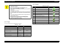
Symbols Used in this Manual
Various symbols are used throughout this manual either to provide
additional information on a specific topic or to warn of possible danger
present during a procedure or an action. Be aware of all symbols when
they are used, and always read NOTE, CAUTION, or WARNING
messages.
A D J U S T M E N T
R E Q U IR E D
C A U T IO N
C H E C K
P O IN T
W A R N IN G
Indicates an operating or maintenance procedure, practice
or condition that is necessary to keep the product’s quality.
Indicates an operating or maintenance procedure, practice,
or condition that, if not strictly observed, could result in
damage to, or destruction of, equipment.
May indicate an operating or maintenance procedure,
practice or condition that is necessary to accomplish a task
efficiently. It may also provide additional information that is
related to a specific subject, or comment on the results
achieved through a previous action.
I.ndicates an operating or maintenance procedure, practice
or condition that, if not strictly observed, could result in injury
or loss of life.
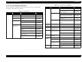
Revision Status
Revision
Issued Date
A
Augusut 1,2002
Description
First Release
EPSON Stylus CX3100/3200
Revision A
Contents
Chapter 1 PRODUCT DESCRIPTION
3.4 Troubleshooting for Motors and Sensors ............................................................ 33
1.1 Overview ............................................................................................................... 9
1.1.1 Basic Functions............................................................................................. 9
1.1.2 Common ....................................................................................................... 9
1.1.2.1 Electrical Specifications ........................................................................ 9
1.1.2.2 Interface............................................................................................... 10
1.1.2.3 Conformity to Safety and EMC Standards.......................................... 10
1.1.2.4 Environmental Conditions................................................................... 10
1.1.2.5 Reliability ............................................................................................ 11
1.1.2.6 Acoustic Noise .................................................................................... 11
1.1.2.7 Weight and Overall Dimensions ......................................................... 11
1.2 Media Specifications ........................................................................................... 12
1.2.1 Black Ink Cartridge..................................................................................... 12
1.2.2 Color Ink Cartridge..................................................................................... 12
Chapter 2 Operating Principles
2.1 Overview .............................................................................................................
2.1.1 Mechanism..................................................................................................
2.1.1.1 Printer Mechanism ..............................................................................
2.1.1.2 Scanner Mechanism ............................................................................
2.1.2 Electric Circuit............................................................................................
14
14
14
15
15
Chapter 3 Troubleshooting
3.1 Troubleshooting at Unit Level.............................................................................
3.1.1 Printer / Scanner does not operate at all
even with power turned on ........................................................................
3.1.2 Error is detected ..........................................................................................
3.1.3 Trouble related to Print ...............................................................................
3.1.4 Paper feeding is not normally carried out...................................................
3.1.5 Operation Panel faulty ................................................................................
3.2 Troubleshooting for Printer .................................................................................
3.3 Troubleshooting for Scanner ...............................................................................
18
20
21
21
22
22
23
30
Chapter 4 Disassembly and Assembly
4.1 Overview .............................................................................................................
4.1.1 Precautions..................................................................................................
4.1.2 Tools ...........................................................................................................
4.1.3 Screws.........................................................................................................
4.1.4 Service Dispatch Standard..........................................................................
4.2 Disassembly Process ...........................................................................................
4.2.1 Scanner Unit Removal................................................................................
4.3 Scanner Unit Disassembly...................................................................................
4.3.1 Hinge Removal ...........................................................................................
4.3.2 Upper Housing Removal ............................................................................
4.3.3 Motor Unit Removal...................................................................................
4.3.4 CCD Module Removal ...............................................................................
4.3.5 Panel Circuit Board Removal .....................................................................
4.4 Disassembly of Printer ........................................................................................
4.4.1 Middle Housing Removal...........................................................................
4.4.2 Print Head Removal....................................................................................
4.4.3 ASF Unit Removal .....................................................................................
4.4.4 Waste Ink Pad Removal .............................................................................
4.4.5 CR Motor Removal ....................................................................................
4.4.6 Holder Shaft Unit Removal ........................................................................
4.4.7 Front Frame Unit Removal.........................................................................
4.4.8 Main Board Removal..................................................................................
4.4.9 Power Unit Removal ..................................................................................
35
35
36
36
37
38
38
40
40
41
42
43
43
44
44
46
48
49
50
52
53
54
56
Chapter 5 Adjustment
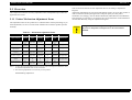
5.1 Overview .............................................................................................................
5.1.1 Printer Mechanism Adjustment Items ........................................................
5.1.2 Dedicated Tools ..........................................................................................
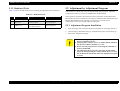
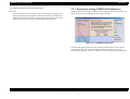
5.2 Adjustment by Adjustment Program...................................................................
58
58
59
59
6
EPSON Stylus CX3100/3200
Revision A
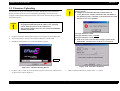
5.2.1 Adjustment Program Installation ................................................................ 59
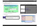
5.2.2 Adjustment Program Start .......................................................................... 60
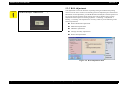
5.2.3 Destination Setting (EEPROM Initialization) ............................................ 61
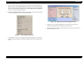
5.2.4 Head ID Input ............................................................................................. 62
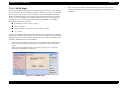
5.2.5 Bi-D Adjustment......................................................................................... 63
5.2.6 USB ID Input .............................................................................................. 65
5.2.7 Top Margin Adjustment ............................................................................. 66
5.2.8 First Dot Position Adjustment .................................................................... 67
5.2.9 Head Cleaning ............................................................................................ 68
5.2.10 Ink Charge ................................................................................................ 68
5.2.11 Protection Counter .................................................................................... 69
5.2.12 EEPROM Data Backup ............................................................................ 70
5.2.13 Check Pattern Printing .............................................................................. 70
5.2.13.1 A4 Plain Paper Printing ..................................................................... 70
5.2.14 EEPROM Data.......................................................................................... 71
5.3 Firmware Uploading............................................................................................ 72
Chapter 6 Maintenance
6.1 Overview .............................................................................................................
6.1.1 Cleaning ......................................................................................................
6.1.2 Maintenance of the Scanner........................................................................
6.1.2.1 Lubrication Points of the Scanner (TBD)............................................
6.1.3 Maintenance of the Printer..........................................................................
6.1.3.1 Head Cleaning .....................................................................................
6.1.3.2 Maintenance Error ...............................................................................
6.1.3.3 Lubrication Points of the Printer .........................................................
75
75
75
75
76
76
76
76
Chapter 7 Appendix
7.1 Connectors...........................................................................................................
7.1.1 Connector Assignments ..............................................................................
7.2 Circuit Board Component Layout .......................................................................
7.3 Electric Circuit Diagrams ....................................................................................
7.4 Exploded Diagrams .............................................................................................
7.5 ASP List...............................................................................................................
81
81
82
83
88
89
7
CHAPTER
1
PRODUCT DESCRIPTION
EPSON Stylus CX3100/3200
Revision A
Reduced (Minimize) Margin Copy mode
1.1 Overview
This mode is basically the same as the standard copy mode, but the bottom
margin is 3 mm.
This section describes the specifications for the SPC (Scanner, Printer, Copier)
machine “Stylus CX3100/3200”.
Repeat Copy mode
Mini photo stickers can be produced.
1.1.1 Basic Functions
2-up Copy mode
The functions of Stylus CX3100/3200 are as described below:
Two pages of the original is shrunk and printed on one page. Consumption of
copy paper can be saved.
Printer function
The Printer function produces photo quality output on the Epson special coated
papers with BorderFree feature.
Mirror Copy mode
The original can be flipped from left to right and copied onto the Iron-on Cool
Peel Transfer Paper.
Print head
Bk: 48 nozzles in each of 3 rows (144 nozzles in total)
YMC: 48 nozzles for each
Scanner function
1.1.2 Common
The image can easily be acquired on the PC by means of the “Scan” button.
The specifications described below are common to the scanner and printer.
The maximum optical resolution of scanning is 600 dpi x 1200 dpi and pixel
1.1.2.1 Electrical Specifications
depth is 48-bit at the ADC output, 24-bit when passing to a PC.
Standalone Copier function
Table 1-1. AC Input
The Product has the Standalone Copier function that reproduces photo quality
copies on the Epson special coated papers without PCs. The use of the latest print
technology mounted on the Product achieves the highest standalone copy speed
among the same class of the products.
Standard Copy mode
Photograph copy
Small Margin Copy mode
120 V Model
220-240 V Model
Rated voltage (VAC)
100
120
220-240
Input voltage (VAC)
90-110
108-132
198-264
0.6
0.6
0.3
Rated current (A)
This mode is used for the standard copier function. The bottom margin is 14
mm.
BorderFree Copy mode
100 V Model
Rated frequency range (Hz)
50-60
Input frequency range (Hz)
49.5-60.5
Power consumption (W)
Approx. 22 W (Standalone copying, ISO10561 Letter
Patter, Plain Paper - Normal)
Approx. 6.5 W (Standby)
The minimum copy margin is 1.5 mm.
PRODUCT DESCRIPTION
Overview
9
EPSON Stylus CX3100/3200
Revision A
1.1.2.4 Environmental Conditions
NOTE: The product is Energy Star compliant.
Temperature
NOTE: The holding current to the motors is reduced when the printer has stayed
in non-operation status for 5 minutes.
Operating
10 ~ 35 °C
NOTE: The Scanner lamp is turned off when the Scanner has stayed in nonoperation status for 15 minutes.
Non-operating
-20 ~ 60 °C (In the shipment container.)
1.1.2.2 Interface
NOTE: 1 month at 40 °C or 120 hours at 60 °C
In compliance with USB (Universal Serial Bus) Revision 1.1
Humidity (no condensation)
Operating
Connector
20 ~ 80%RH
USB Series B
Non-operating
1.1.2.3 Conformity to Safety and EMC Standards
5 ~ 85%RH (In the shipment container.)
Table 1-2. Conformity to Safety and EMC Standards
Resistance to physical shock
100 V Model
120 V Model
220-240 V Model
Safety
-
• UL1950
• CSA22.2 No.950
• EN 60950
EMC
• VCCI Class B
• Guideline for the Suppression
of Harmonics in Household
and General-Use Equipment
• FCC part15
subpart B class B
• CSA C108.8 class
B
• EN 55022 (CISPR
Pub.22) class B
• EN 55024
• EN 61000-3-2
• EN 61000-3-3
• AS/NZS 3548
Class B
Operating
1 G, 1 x 10⁻³ second
Non-operating
2 G, 2 x 10⁻³ second (In the shipment container.)
Resistance to physical vibration
Operating
0.15 G
Non-operating
0.50 G (In the shipment container.)
PRODUCT DESCRIPTION
Overview
10
EPSON Stylus CX3100/3200
Revision A
1.1.2.5 Reliability
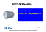
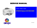
1.1.2.7 Weight and Overall Dimensions
Total print volume
Weight
50,000 pages (A4, Letter)
Print head life
7.5kg
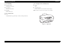
Overall Dimensions
4000 million dots/nozzle
Scan head
475 mm x 389 mm x 235 mm (Width x Depth x Height)
NOTE: Neither the rubber feet nor the paper tray is included.
MCBF 30,000 cycles
1.1.2.6 Acoustic Noise
Level
52 dB (Standalone copy, Plain Paper - Normal, according to ISO7779)
Figure 1-1. Appearance
PRODUCT DESCRIPTION
Overview
11
EPSON Stylus CX3100/3200
Revision A
1.2 Media Specifications
1.2.1 Black Ink Cartridge
Color
Black
Print capacity
600 pages (A4, ISO/IEC10561 Letter Pattern at 360 dpi)
1.2.2 Color Ink Cartridge
Color
Magenta, Cyan and Yellow
Print capacity
300 pages (A4, ISO/IEC10561 Letter Pattern at 360 dpi)
PRODUCT DESCRIPTION
Media Specifications
12
CHAPTER
2
OPERATING PRINCIPLES
EPSON Stylus CX3100/3200
Revision A
2.1 Overview
PF Motor
This Chapter describes the operating principles of the mechanism and electric circuits
of EPSON Stylus CX3100/3200.
EPSON Stylus CX3100/3200 roughly consists of a printer and a scanner. The
mechanism can be divided into the printer and the scanner. The electric circuit includes
the Main Board circuit, Power Supply Board circuit, scanner carriage circuit and
control panel circuit.
2.1.1 Mechanism
Paper
Eject
Unit
Print Head
ASF Mechanism
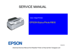
2.1.1.1 Printer Mechanism
The printer mechanism comprises the Carriage carrying the print head, the CR Motor
for driving the carriage in the lateral direction in the printing range, the Capping Unit
for preventing the print head from drying, the PF Motor for transporting the paper, the
ASF Unit for loading paper by the driving force from the PF motor, and the Paper Eject
Unit for ejecting the paper after printing.
Capping Unit
CR Motor
Figure 2-1. Outline of Printer Mechanism
Operating Principles
Overview
14
EPSON Stylus CX3100/3200
Revision A
2.1.1.2 Scanner Mechanism
2.1.2 Electric Circuit
The scanner consists of the Scanner Carriage Unit comprising the CCD for capturing
images and the light source for illuminating the document, the Scanner Motor and
Timing Belt for moving the scanner carriage unit along the document surface, and the
Scan HP Detector for detecting the position of the scanner carriage unit.
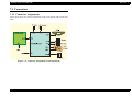
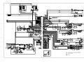
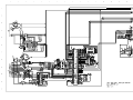
The electric circuit boards of Stylus CX3100/3200 are as follows:
C497MAIN Board (main circuit board)
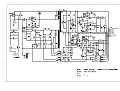
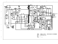
C497PSB/C497PSE Board (power supply circuit board)
This circuit board supplies the following voltages:
Document
Scanner Carriage Unit
Scanner HP
Detector
Scanner Motor
+3.3V:
For logic
+42V:
Driving power
+12V:
Power to the scanner
Scanner circuit board
Panel circuit board
Figure 2-2. Scanner Mechanism
Figure 2-3. Electric Circuit Block
Operating Principles
Overview
15
EPSON Stylus CX3100/3200
Revision A
Table 2-1. Functions of Major Elements - C497MAIN
Location
Name
IC1
C90A20**
IC5
MBM29LV800BC-PFTN
or the equivalent
Description
CPU
• Built-in RAM 10kB,
Built-in Flash ROM 256KB
• 144-pin, LQFP,
Driving frequency: 48MHz
• Control, image processing C90A20
64Mbit Flash ROM
• Stores firmware
ASIC
• Motor control
• Head control
• Panel sensor input and output control
• USB I/F
• EEPROM
• Storage of default setting and backup of
various parameters
• Reset function
• Timer function
CR Motor driver
IC2
E05C08**
IC4
RTC9822
IC7
A6615
IC11
LB11847
IC6
E09A29LA
IC8
K4S641632D
16Mbit SDRAM
• System memory
IC9
K4S641632D
16Mbit SDRAM
• Work area for copy functions
Operating Principles
Scanner motor driver
Head drive control IC
• Supplies COMMON+42 V
Overview
16
CHAPTER
3
TROUBLESHOOTING
EPSON Stylus CX3100/3200
Revision A
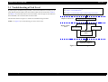
3.1 Troubleshooting at Unit Level
Identifying the Trouble
By following this troubleshooting procedure, when some trouble has occurred, you can
easily identify the unit which is the cause of the trouble, from its observation. Table 3-1
and Table 3-2 list the observations of various troubles. Once the type of the trouble has
been identified, refer to the flowchart for that trouble.
The flowchart shown in Figure 3-1 outlines the troubleshooting procedure.
Table 3-1 "LCD Indication"
Table 3-2 "Observations and Troubleshooting Flowcharts"
Repair at Unit Level
Diagnosing the Following Units
NOTE: See page 33 for troubleshooting for motors and sensors.
Repair at Parts
Level
Scanner Mechanism
Printer Mechanism
Motor and Sensor
Repair
Disassembly = Chapter 4
Adjustment = Chapter 5
Figure 3-1. Troubleshooting Flowchart
Troubleshooting
Troubleshooting at Unit Level
18
EPSON Stylus CX3100/3200
Revision A
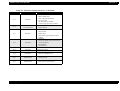
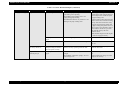
Table 3-1. LCD Indication
Error Status
LCD Indication
(The upper line shows “Error indication” and the
lower line shows descriptive character strings by
scrolling.)
Paper out
Paper out → Load paper in Paper tray and press the
Color copy button.
Paper jam
Paper jam or miss feed → Press the Color copy
button and clear the paper jam by hand if necessary.
• No black ink cartridge → Press the Color copy
button to install new ink cartridge.
• Black ink out → Press the Color copy button to
begin replacing the ink cartridge.
Ink cartridge out / Ink end (black)
Ink cartridge out / Ink end (color)
• No Color ink cartridge → Press the Color copy
button to install new ink cartridge.
• Color ink out → Press the Color copy button to
begin replacing the ink cartridge.
LED Indication
Restoration Method
Power
Error LED
-
Lighting up
-
Lighting up
Remove the jammed paper and press the Color or B&W copy
button.
Lighting up
Move the carriage to the position for replacement by means of
the Color or B&W copy button and replace the black ink
cartridge with a new one.
After replacement, close the scanner unit, and the carriage will
move the printing start position and start printing.
-
Lighting up
Move the carriage to the position for replacement by means of
the Color or B&W copy button and replace the color ink
cartridge with a new one.
After replacement, close the scanner unit, and the carriage will
move the printing start position and start printing.
-
Blinking
Reset the waste ink counter after replacing the waste ink porous
pad.
-
Supply paper and press the Color or B&W copy button.
Waste ink overflow
Printer error → See your documentation and call
service if necessary.
Fatal error
Printer error → See your documentation and call
service if necessary.
-
Lighting up
Turn the power off once and turn it on again. If this turning the
power off and on does not work to recover the printer, make
repairs.
Scanner error → See your documentation and call
service if necessary.
-
Lighting up
Turn the power off once and turn it on again. If this turning the
power off and on does not work to cover the scanner, make
repairs. (Refer to “Troubleshooting for Scanner” (p.30).
Blinking
Lighting up
Close the scanner unit.
Scanner unit open
Troubleshooting
Scanner unit open → Close the scanner unit.
Troubleshooting at Unit Level
19
EPSON Stylus CX3100/3200
Revision A
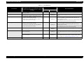
Table 3-2. Observations and Troubleshooting Flowcharts
Observation
Details
Refer to
Power is on but not
operating
LED does not turn on at all.
Printer mechanism does not operate at all.
Scanner mechanism does not operate at
all.
Flowchart 3-1
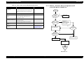
3.1.1 Printer / Scanner does not operate at all
even with power turned on
Start
Error is detected
LCD/LED panel shows error status.
Flowchart 3-2
Trouble related to
print
Printing is not done.
Print is abnormal (Dot missing, etc.).
Print quality is bad.
Flowchart 3-3
Paper feeding is not
normally carried out.
Paper feeding is not done.
Paper jam occurs.
Paper start up position is not correct.
Flowchart 3-4
Faulty operation
panel
Pressing a button does not work.
Flowchart 3-5
Trouble related to
scanner
Scanner does not operate normally.
Refer to
“Troubleshooting for
Scanner” (p.30)
AC power /
voltage
is normal?
No
Input normal
power.
Yes
Yes
Fuse (F1) of power
board is blown?
Replace fuse.
Disconnect CN10 of
main board and turn
power on again.
No
No
Check output voltage of
power board CN2.
Fuse is blown
again?
Yes
No
Power board
output voltage is
normal?
Yes
Replace power board
Replace main board
Check motors, head
and other parts
End
Flowchart 3-1.
Troubleshooting
Troubleshooting at Unit Level
20
EPSON Stylus CX3100/3200
Revision A
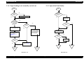
3.1.2 Error is detected
3.1.3 Trouble related to Print
Start
Start
Execute test printing
Check error contents by
LCD (See Table 3-1).
No
Printing was
successfully
done?
Yes
Turn power off, unlock
CR and move CR with
hand.
Printer error?
Yes
No
No
Yes
Ink cartridge out
error?
Replace Ink cartridge
with a new one by
operation panel.
CR cartridge can
move smoothly?
Execute print
adjustment (Refer to
“Adjustment” on
page 57)
Print quality
is normal?
No
Yes
All the cables
are connected
properly to main
board?
Yes
No
Connect correctly
Execute cleaning
Yes
No
No
Maintenance error
No
Check CR motor and if
there is no problem,
replace main board.
Ink cartridge out
error is cleared?
No
Problem is
solved?
Problem is
solved?
Replace Ink cartridge
and execute test print.
Yes
Yes
Replace waste ink porous
pad and reset counter.
(Refer to “Disassembly and
Assembly” on page 34 and
“Adjustment” on page 57)
Yes
Refer to Table 3-5
No
Problem is
solved?
Yes
Yes
Problem is
solved?
Carriage smoothly
moves?
Yes
No
No
Refer to Table 3-5
Check whether Head
FFC is connected
properly to head.
Replace main board
Refer to Table 3-5
No
Yes
Problem is
solved?
End
End
End
End
Flowchart 3-3.
Flowchart 3-2.
Troubleshooting
End
Troubleshooting at Unit Level
21
Stylus Photo 720
Revision B
3.1.4 Paper feeding is not normally carried out
3.1.5 Operation Panel faulty
Start
Paper is
correctly set in
ASF?
Start
No
Operation
Panel is connected
properly with
cable?
No
Set paper correctly.
Yes
Yes
Paper loading
roller and PF roller
are correctly
rotating?
Connect correctly
Operation panel
again.
No
Yes
No
Problem is
solved?
PF motor is
driving?
Yes
No
Remove foreign matters,
if any, from paper route.
Yes
Check whether connector
of PF motor is connected
to CN7 of main board. If
it is connected properly,
replace main board.
Clean rollers on paper
route. (Refer to
“Maintenance” on
page 74)
Replace operation
panel.
No
Problem is
solved?
Yes
No
Replace main
board.
Problem is
solved?
Yes
Refer to Table 3-5
End
End
End
End
Flowchart 3-4.
Troubleshooting
Flowchart 3-5.
Troubleshooting at Unit Level
22
EPSON Stylus CX3100/3200
Revision A
3.2 Troubleshooting for Printer
Table 3-3. Printer Errors (continued)
Observation
This section describes repair / service of the Printer Mechanism. Listed below are
various problems which may occur, observations of such problems, check point and
remedies. For the pertinent observation, check the functions of the parts in question
according to Check Point.
Paper jam
Cause
When paper is not ejected,
paper jam error is indicated.
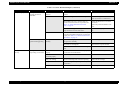
Table 3-3. Printer Errors
Observation
Cause
Ink shortage /
Ink out
• If any ink cartridge comes
close to Ink out, Printer
continues printing in ink
shortage status.
• If cartridge is completely
empty, Printer indicates ink
out error and stop printing.
Paper out
• When Printer cannot load
paper, paper out error is
indicated.
• Paper stops in front of PE
detector or paper is not
loaded.
• Paper is loaded without
adjusting paper to right
edge guide.
Remedy
• Start cleaning execution command on
Panel or by Utility.
• Carriage automatically moves to
replacement position.
• Replace ink cartridge with a new one.
(1)Set paper on tray if paper is out.
(2)If paper is stopped midway, pull paper
out and check that paper is not folded.
Loosen paper well and set it again with
edge guide adjusted to paper width.
(3)Execute “Load/Eject”.
• Clean paper loading roller. Or replace
paper loading roller.
• Check that gears for ASF are engaged
correctly.
Ink cartridge out • If Ink cartridge is not
correctly set, printer
indicates ink cartridge out
error.
Maintenance
error
Fatal error
Troubleshooting
Troubleshooting for Printer
Waste ink overflow
indication is displayed if the
total amount of ink
consumed by cleaning and/or
flushing has exceeded the
predetermined limit.
• Carriage error:
• Home of carriage can not
be recognized.
• Abnormal external power
was applied to carriage or
carriage operation is
obstructed during printing.
• PF error:
PF motor does not operate
adequately to feed paper by
the required distance.
Remedy
• Select “Load/Eject” from menu and
execute it.
(1)Open the printer cover and remove
with hand all the paper inside the
printer and all the set paper if there is
paper on the way of loading.
(2)Check that there is no paper in the
printer and set paper again and execute
paper loading and paper ejection.
Then, this error display will be cleared
and if there is print data, print
operation will start.
• Check whether Platen gap is correct
value. (Refer to “Adjustment” on
page 57)
• Check CSIC connection circuit.
• Replace ink cartridge.
After replacing waste ink porous pad,
reset waste ink overflow counter. (Refer
to “Protection Counter” on page 69)
• Several seconds or more after turning
power off, press power switch to turn
power on.
• Open maintenance cover and check
that there is no obstacle in the carriage
moving zone.
If the error is not cleared even by the
above operation, check the followings:
• CR HP sensor/Harness
• CR Lock mechanism
• Main board
23
EPSON Stylus CX3100/3200
Revision A
Table 3-4. Printer Mechanism Repair
Observation
Faulty pump mechanism
Ink is not absorbed at all
or ink absorption is poor.
Condition
When power is turned on,
PF motor operation is
abnormal.
Ejected ink does not flow
into Ink Eject tube.
Ink is not absorbed from
head to cap.
Troubleshooting
Cause
Check Point
Remedy
There are foreign matters on
the PF gear.
Operate the platen drive gear by hand and check
whether it rotates properly.
Remove foreign matters.
Replace the printer mechanism.
PF motor is faulty.
Check whether the internal coil resistance is just
as specified and whether the harness is connected
properly. See Table 3-13, “Motor Resistance and
Check Point,” on page 33.
Replace the printer mechanism or PF
motor.
Pump tube is crashed.
Check tube with the naked eye.
Replace the printer mechanism or pump
unit.
Capping unit is faulty.
Check capping rubber with the naked eye.
Replace the printer mechanism or
capping unit.
Tube is projecting from cap.
Check with the naked eye whether tube is
projecting from cap.
Connect the tube correctly.
Pump tube is entangled in the
pump unit.
When cap assembly slides up completely, check
whether there is a small slack in pump tube
between cap assembly and pump unit.
Remove the entangled pump tube
carefully, correct the tube condition and
connect it to the cap assembly.
Dirt on cap
Check whether any foreign matter is adhering to
cap.
Remove foreign matters from the cap
and if the cap is damaged, replace it
with a new one.
Faulty slide-up of cap
Check whether two compression springs are set
on cap assembly.
Set the compression springs on the cap
assembly.
Troubleshooting for Printer
24
EPSON Stylus CX3100/3200
Revision A
Table 3-4. Printer Mechanism Repair (continued)
Observation
Faulty carriage operation
Condition
When power is turned on,
carriage operation is
abnormal.
Abnormal carriage
operation during printing
Printing is not carried out
correctly.
Troubleshooting
Carriage moves correctly
but printing is not normal.
Cause
Check Point
Remedy
There is an obstacle in CR
shift area.
Check with the naked eye whether there is an
obstacle.
Remove the obstacle.
CR lock is not released.
Check that change lever is in the front of printer.
Return the change lever to the back of
printer by tweeters or a small driver.
Check whether the CN13 connector and coil
resistance of the PF motor are as specified. See
Table 3-13, “Motor Resistance and Check
Point,” on page 33.
Connect the PF motor to CN7 on the
main board.
Replace the printer mechanism or PF
motor.
Check whether any gear is damaged on the
torque transmission route of PF motor.
Replace the damaged gear with a new
one.
Faulty CR motor
Check whether the internal coil resistance is just
as specified and whether the harness is connected
properly. See Table 3-13, “Motor Resistance and
Check Point,” on page 33.
Replace the CR motor.
Carriage does not move
smoothly.
Operate the carriage by hand and check whether
carriage moves smoothly.
Clean the CR guide shaft and lubricate.
Check tension of timing belt.
Adjust tension or replace the belt.
Check whether there is an obstacle in carriage
route.
Remove the obstacle.
Head FFC is not connected
properly.
Check whether Head FFC is connected properly
to CN8 and CN9 of main board.
Connect the FFC correctly.
Inside of FFC is not
connected properly.
Check FFC by tester.
Replace the FFC.
Faulty ink cartridge
Set new ink cartridge and execute test printing.
Replace the ink cartridge.
Faulty head unit
Repeat cleaning and test printing alternately
several times.
Replace the head unit.
Faulty head cleaner
Check whether dust is adhering to head cleaner.
Clean or replace the head cleaner.
Troubleshooting for Printer
25
EPSON Stylus CX3100/3200
Revision A
Table 3-4. Printer Mechanism Repair (continued)
Observation
Faulty print
Condition
Faulty printing occurs at
specific dots.
Sometimes dots are
missing.
Black points or dots are
printed.
Troubleshooting
Cause
Check Point
Remedy
Head surface is dirty.
(Dot missing occurs)
Repeat cleaning and test printing alternately
several times.
Clean with a swab fixed to a stick.
Faulty head FFC
Check whether head FFC is damaged.
Replace the head FFC with a new one.
Faulty head unit
Repeat cleaning and nozzle checking alternately
several times.
If the condition is not improved even
after cleaning, replace the head.
Capping porous pad is in
contact with head surface.
Check capping porous pad with the naked eye.
Replace the capping porous pad, if its
shape is deformed or it is damaged.
Head surface is dirty.
(Dot is missing occurs)
Repeat cleaning and nozzle checking alternately
several times.
Clean with a swab fixed to a stick.
Inside of FFC is not
connected properly.
Check FFC by tester.
Replace the head FFC.
Head FFC is not connected.
Check whether Board and Carriage FFC are
connected.
Connect the FFC correctly.
Faulty Head unit.
Execute cleaning several times, and Check
nozzle.
If the condition is not improved even
after cleaning, replace the head.
Faulty ink cartridge.
Set new ink cartridge and check nozzle.
Replace the ink cartridge.
Head FFC is not connected.
Check whether Board and Carriage FFC are
connected.
Connect the FFC correctly.
Faulty head unit
Check connection with head FFC.
If connection with the FFC is not faulty,
replace the head.
Troubleshooting for Printer
26
EPSON Stylus CX3100/3200
Revision A
Table 3-4. Printer Mechanism Repair (continued)
Observation
Faulty print
Troubleshooting
Condition
Cause
Check Point
Remedy
Vertical line is not
straightly lined.
Bi-D adjustment has not been
made.
Make Bi-D adjustment.
Refer to “Adjustment” (p.57)
White line appears in
output data.
Dirt is adhering to CR guide
shaft.
Check whether dirt is adhering to the surface of
CR guide shaft.
Clean the surface of CR guide shaft with
a dry and soft cloth.
Faulty CR guide shaft.
Check that CR guide shaft is steadily installed in
the designated position.
Check that CR guide shaft surface is flat.
Reinstall the CR guide shaft on the
mounting slats (wing boards) on both
sides of the frame, and fix it with the rod
spring.
Replace the CR guide shaft with a new
one.
Faulty slide operation of
Carriage.
Check whether sufficient oil is remaining on the
surface in the carriage slide area on the Paper
Eject Frame.
Clean the surface in the carriage slide
area and apply a specified amount of G26. (Refer to “Maintenance” (p.74))
Paper feeding route is dirty.
Check whether PF roller is dirty.
Clean the surface of the PF roller
carefully with a soft brush.
Damaged gear
Check whether the following parts are not
damaged.
• Combination gear16, 21.6
• Combination gear 11.6, 36.8
• Spur gear 73.6
• Spur gear 25.6
Replace the damaged part with a new
one.
Platen gap is not correct.
Adjust platen gap.
Refer to “Adjustment” (p.57)
As head surface is dirty, dot
jet direction is slanting.
Repeat cleaning and test printing alternately
several times.
Clean with a swab fixed to a stick.
Check whether dust is adhering to head cleaner.
Clean or replace the head cleaner.
Faulty ink cartridge
Set new ink cartridge and execute test printing.
Replace the ink cartridge.
Faulty head unit
Clean several times, and execute test printing.
Replace the head unit.
Troubleshooting for Printer
27
EPSON Stylus CX3100/3200
Revision A
Table 3-4. Printer Mechanism Repair (continued)
Observation
Faulty paper loading
Troubleshooting
Condition
Check Point
Remedy
Paper loading roller worn
Check whether paper loading roller rotates when
paper feeding is not operating.
Check whether paper loading roller is not
slipping during paper feeding.
Check that Micro Pearl or oily substance is not
adhering to the paper loading roller
Clean the paper loading roller with the
cleaning sheet. If this cleaning does not
work to improve the condition, replace
the paper loading roller.
In order to remove Micro Pearl from the
surface of LD roller, install the cleaning
sheet up side down inside ASF. Grasp
the upper end of the sheet steadily and
try paper loading from printer driver. In
order to remove oily substance, staple a
cloth soaked in alcohol to a post card
and clean the roller by the same
method.as above.
Check whether the gears for driving the
PF roller are engaged correctly.
Faulty operation of ASF
hopper
Check ASF hopper operation with the naked eye. Replace the ASF.
Faulty clutch mechanism
Check whether clutch mechanism is damaged.
Replace the clutch mechanism with a
new one.
Multiple sheets of paper
are always drawn in
Paper Return (preventive
multiple feeding mechanism)
does not operate correctly.
When paper is loaded, check whether Paper
Return is correctly operating inside the ASF.
Reassemble the torsion spring 25.7
inside the ASF frame.
Paper is loaded even
without print job
Faulty operation of ASF
hopper
Check whether the tip of change lever is
damaged.
Check whether compression spring 1.47 is not
off the change lever.
Replace the change lever with a new
one.
Set the compression spring 1.47 on the
change lever correctly.
Paper is not loaded.
Cause
Troubleshooting for Printer
28
EPSON Stylus CX3100/3200
Revision A
Table 3-4. Printer Mechanism Repair (continued)
Observation
Faulty paper ejection
Printer stops during
initialization
Condition
Paper is jammed on the
way of paper ejection.
Cause
Remedy
Faulty installation of Star
Wheel Roller
Check that Star Wheel Roller is set on paper
eject frame.
Remove the jammed paper, set the Star
Wheel Roller in the paper eject frame
steadily.
If the hook of the Hook Roller is
damaged, replace it with a new one.
Faulty operation of Paper
Eject Roller
Check whether Paper Eject Roller rotates
correctly.
Check whether the gears for driving the
Paper Eject Roller are engaged
correctly.
Paper is ejected without
being printed.
Faulty HP/PE sensor
Check whether CN4 Connector is not
disconnected from HP/PE sensor cable on main
board or sensor.
Connect CN4 connector cable to CN4
on the main board.
Replace HP /PE sensor with a new one.
Printer error is indicated.
Faulty PE sensor
Check PE sensor signal level.
(Refer to Table 3-14, “Sensor Check,” on
page 33)
Replace the PE sensor
Faulty CR HP sensor
Check CR HP sensor signal level.
(Refer to Table 3-14, “Sensor Check,” on
page 33)
Head FFC is not connected
properly.
Check whether Head FFC is connected properly. Connect the Head FFC
Faulty CR motor
Check whether CR motor cable is connected
properly.
If there is no problem with cable
connection, replace the CR motor.
Check whether the internal coil resistance is just
as specified and whether the harness is connected
properly. See Table 3-13, “Motor Resistance
and Check Point,” on page 33.
Replace the CR motor.
Check whether PF motor cable is connected
properly.
If there is no problem with cable
connection, replace the PF motor.
Check whether the internal coil resistance is just
as specified and whether the harness is connected
properly. See Table 3-13, “Motor Resistance and
Check Point,” on page 33.
Replace the printer mechanism or PF
motor.
Check whether no gear is damaged in the PF
motor torque transmission route.
Replace the damaged gear with a new
one.
Faulty PF motor
CR lock is not undone.
Troubleshooting
Check Point
Troubleshooting for Printer
29
EPSON Stylus CX3100/3200
Revision A
3.3 Troubleshooting for Scanner
Table 3-6. Observation of Trouble and Reference for Remedy
This section describes repair / service for the Scanner mechanism. In troubleshooting,
first the trouble is identified at the unit level based on the observation.
According to the observation as described in Table 3-6, perform the necessary
checking by referring to the appropriate table.
Table 3-5. Scanner Errors at User Level
Error
Cause
•
Lamp
has
burnt out.
Scanner error
• Power is turned on
without unlocking the
scanner.
• The scanner carriage is
interfering with any other
part.
Command error Undefined command is
detected.
Scanner open
Scanner cover is open.
Troubleshooting
•
•
•
•
Remedy
Unlock the CR.
Replace the scanner lamp.
Replace the scanner carriage unit.
Remove the obstacle.
When correct command is received, error
status is cancelled.
Turn the power off once and then turn it on
again.
Close the cover.
Observation
Reference for
Remedy
Description of Trouble
Even with power turned on, the
machine does not operate.
The machine does not operate for
initialization.
Table 3-7
“Fatal error” occurred.
Indication error occurs and it is
not cleared even after power is
turned off once and then turned
on again.
CR unit does not operate.
Table 3-8
CR unit operates but error is indicated.
Table 3-9
The fluorescent lamp does not turn on.
Picture is not read clearly.
Picture is not read clearly.
“Communication error”.
Indication error occurs and
when communication with the
host is tried again,
“Communication error” recurs.
USB interface error
Table 3-10
Table 3-11
Table 3-12
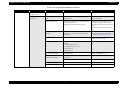
Table 3-7. Scanner does not operate for initialization
Cause
Connector is
disconnected.
Troubleshooting for Scanner
Step
Check Point
Yes/No
Remedy
1
Check all connectors for
disconnection?
Yes
Connect the disconnected
connector.
No
Replace the main board.
30
EPSON Stylus CX3100/3200
Revision A
Table 3-8. Carriage unit does not operate
Cause
Step
Connector
CN11 on main
board is
disconnected.
Faulty carriage
moving
mechanism
1
2
3
Faulty CR
motor
4
Defective main
board
Troubleshooting
5
Check Point
Connector CN11 on main
board is disconnected?
Grease is applied
properly?
• Does CR motor
operate when power is
turned ON with upper
case of Scanner
removed?
• Does CR unit move
with CR motor
removed?
Disconnect connector
CN7 on main board and
measure with a tester the
coil resistance between
pins 2 and 4 and between
1 and 3 on motor side.
See Table 3-13, “Motor
Resistance and Check
Point,” on page 33
-
Yes/No
Table 3-9. Carriage operates but error indicated
Remedy
Step
Check Point
Yes/
No
Upper case of
scanner is removed.
1
Upper case of
scanner is removed.?
Yes
Defective main
board
2
-
-
Defective CR HP
sensor
3
-
-
Cause
Connect the connector.
Yes
No
No
Apply grease at
designated point
(Refer to
“Maintenance” (p.74))
Check the carriage
moving mechanism,
replace the relevant
parts or remove and
reinstall them.
Replace the CR motor
Cause
Replace the main board
Step
Check Point
Connector
CN1 on main
board is
disconnected.
1
Connector of
CCD module is
disconnected.
2
Connector of CCD
module is disconnected?
3
Fluorescent lamp is not
set correctly in connector
on inverter board?
Defective lamp
-
Install the upper case.
Replace the main board.
Replace the CR HP
sensor.
Table 3-10. Fluorescent lamp does not turn on
Fluorescent
lamp is not set
correctly in
connector on
inverter board.
No
Remedy
Connector CN1 on main
board is disconnected?
Yes/No
Yes
Yes
Remedy
Connect the connector
CN1 on the main
board.
Connect the connector
on the CCD module.
Set the lamp correctly
on the inverter board.
No
4
Lamp turns on after
replaced?
Yes
Replace the CCD
module.
Defective
inverter board
5
Inverter board is normal
after replaced?
Yes
Replace the CCD
module.
Defective main
board
6
-
-
Replace the main
board.
Troubleshooting for Scanner
31
EPSON Stylus CX3100/3200
Revision A
Table 3-11. Picture can not be read clearly
Cause
Step
Dirt on mirror
inside CR unit
1
Defective CCD
module
Defective main
board
Check Point
Picture can be read
clearly after mirror is
cleaned?
Yes/No
No
2
-
-
3
-
-
Remedy
Clean fluorescent
lamp surface.
Replace the CCD
module.
Replace the main
board.
Table 3-12. USB Interface error
Cause
Step
Check Point
Yes/No
Host PC does
not support
Windows 98
essentially.
1
On Windows, open
“My computer” →
“Property” → “Device
manager”. “Universal
serial bus controller” is
effective?
No
Change the host.
Printer driver
is not
installed
correctly.
1
On Windows, open
“My computer” →
“Property” → “Device
manager”. Printer driver
is not installed in
“Other devices”?
Yes
Delete the driver and
install it again
according to
operation manual.
Defective
USB cable
2
Operation is normal if
USB cable is replaced?
Yes
Replace the USB
cable.
Defective
main board
3
-
-
Replace the main
board.
Troubleshooting
Remedy
Troubleshooting for Scanner
32
EPSON Stylus CX3100/3200
Revision A
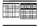
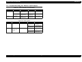
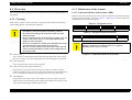
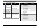
3.4 Troubleshooting for Motors and Sensors
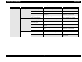
Table 3-13. Motor Resistance and Check Point
Section
Printer
Scanner
Motor Name
Location
Check Point
Resistance
CR motor
CN13
(Main board)
Pin 1 & 3,
Pin 2 & 4
7.8 Ω ± 10%
PF motor
CN14
(Main board)
Pin 1 & 3,
Pin 2 & 4
5.4 Ω ± 10%
CR motor
CN7
(Main board)
Pin 1 & 2,
Pin 3 & 4
26 Ω ± 7%
Table 3-14. Sensor Check
Section
Printer
Sensor Name
HP/ PE sensor
Location
CN4 / Pin 1 & 2
Signal Level
Off:
less than 0.7V
On:
2.4V and over
Scanner
Scanner
carriage HP
sensor
Troubleshooting
CN2 / Pin 1 & 2
•
•
•
•
Sensor Status
Out of HP zone
No paper
Within HP zone
There is paper
Off:
less than 0.7V
Not at home
position
On:
2.4V and over
Within home
position zone
Troubleshooting for Motors and Sensors
33
CHAPTER
4
DISASSEMBLY AND ASSEMBLY
EPSON Stylus CX3100/3200
Revision A
4.1 Overview
This section describes procedures for disassembly and assembly of main components
of the product. Unless otherwise specified, disassembly units or components can be
reassembled by reversing the disassembly procedure. Things, if not strictly observed,
that could result in injury or loss of life are described under the heading “WARNING”.
Precautions for any disassembly or assembly are described under the heading
“CAUTION”. Chips for disassembling procedures are described under the heading
“CHECK POINT”
W A R N IN G
Disconnect the power cable before disassembling or assembling
If the assembling procedure is different from the reversed procedure of the
disassembling, the procedure is described under the heading “REASSEMBLY”. Any
adjustment required after disassembling the units are described under the heading
“ADJUSTMENT REQUIRED”. When you have to remove any units or parts that are
not described in this chapter, refer to the exploded diagrams in the appendix.
Read precautions described in the next section before starting.
4.1.1 Precautions
See the precautions given under the handling “WARNING” and “CAUTION” in the
following column before disassembling and assembling the product.
W A R N IN G
the printer.
If you need to work on the printer with power applied, strictly
follow the instructions in this manual by paying attention in
order not to get electric shock.
Wear protective goggles to protect your eyes from ink. If ink
gets in your eye, flush the eye with fresh water and see a doctor
immediately.
Always wear gloves for disassembly and re-assembly to avoid
injury from sharp metal edge.
If ink is fitted to skin, flush it out with water and soup. If
inflammation is caused to skin, see a doctor.
To protect sensitive microprocessors and circuitry, use static
discharge equipment, such as anti-static wrist straps, when
accessing internal components.
To prevent consumables form explosion or ignite, do not put it
near fire or throw it into fire.
If developing fluid or oil are fitted to skin or clothes, remove
them completely with waste cloth and wash cleanly with water.
Avant de commencer, assurez vous que l’imprimante soit
eteinte et que le cordon d’alimentation soit debranche.
Lorsque vous changez la pile au lithium, assurez vous que la
nouvelle respecte bien les caracteristiques requises.
Lorque que vous installez la pile au lithium, faites attention a
l’inserer dans le bon sens en respectant la polarite.
Veillez a jeter les piles usagees selon le reglement local.
Ne rechargez pas les piles au lithium.
C A U T IO N
Disassembly and Assembly
Overview
Risque d’explosion si la pile est remplacée incorrectment. Ne
remplacer que par une pile du même type ou d’un type équivalent
recommandé par le fabricant. Eliminer les piles déchargées selon
les lois et les règles de sécurité en vigueur.
35
EPSON Stylus CX3100/3200
Revision A
4.1.3 Screws
C A U T IO N
Use only recommended tools for disassembling, assembling or
adjusting the machine.
Observe the specified torque when tightening screws.
Apply lubricants and adhesive as specified.
Once you have disassembled this machine, make the specified
adjustments.
(See Chapter 5 for details.)
At assembly, make sure that the ink tube has been installed in
the correct position. If it is not in the correct position, ink can
leak.
Never remove the ink cartridge from the carriage unless this
manual specifies to do so.
When transporting the printer after installing the ink
cartridge, be sure to pack the printer for transportation
without removing the ink cartridge.
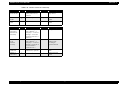
Table 4-2. Screws
No.
Description
1
CBP-Tite *x* F/Ni
2
C.C.P-Tite *x* F/Zb
3
C.B.S. *x* F/Zn
4
C.C.S-Tite *x*
5
C.B.S-Tite *x* F/Zn
6
C.B.S-Tite (P4) *x* F/Zn
7
Bind B-Tite sems W2, 2.5x5F/Zb
8
C.B.(O) SCREW *x* F/Zg
9
C.B.P-Tite *x* F/Zn
10
M3 Hexagon nut
Appearance
4.1.2 Tools
Use only specified tools to avoid damaging the machine.
*x*: Screw nominal size x nominal length
Table 4-1. Tools
Tool Name
Available from
Tool Code
Phillips screw driver #2
EPSON
1080532
Phillips screw driver #1
EPSON
1080530
Tweezers
EPSON
1080561
Hexagonal box driver
(opposite side: 5.5mm)
EPSON
1080584
M3 (5.5mm) wrench
EPSON
-
Radio pliers
EPSON
-
Acetate tape
EPSON
1003963
Tension gauge (2000cN)
EPSON
1213123
Disassembly and Assembly
Overview
36
EPSON Stylus CX3100/3200
Revision A
4.1.4 Service Dispatch Standard
Table 4-3. Check List (continued)
Classification
When this machine is completely repaired and returned to the user, confirm finally
according to Check Points in the right list.
Scanner unit
Part
Mechanism
Table 4-3. Check List
Classification
Printer unit
Part
Check item
Check column
CR mechanism
Check item
Check column
Glass surface is not dirty?
OK / NG
Alien substance is not mixed in the
CR movement area?
OK / NG
CR smoothly operates?
OK / NG
Self test
Operation is normal?
OK / NG
On line test
Print is normally done?
OK / NG
CR operates together with scanner
unit?
OK / NG
Print head (nozzle
check pattern print)
Ink gets out normally from all the
nozzles?
OK / NG
CR makes abnormal sound during
its operation?
OK / NG
CR mechanism
CR smoothly operates?
OK / NG
OK / NG
CR makes abnormal sound during
its operation?
OK / NG
Lamp normally turns on and white
reflection test is done near home
position?
Paper is smoothly loaded?
OK / NG
Paper jam does not happen?
OK / NG
Paper does not warp during paper
loading?
OK / NG
Multiple papers are not fed?
OK / NG
Abnormal sound is not heard during
paper loading?
OK / NG
There is no alien substance at paper
route?
OK / NG
Paper loading
mechanism
Lamp
On line test
On line test
Operation is normal?
OK / NG
Copy
Copy
Local copy is normal?
OK / NG
Adjustment
Designated
adjustment items
Adjustment condition is suitable?
OK / NG
Lubrication
Designated
lubrication items
Lubrication is done at designated
place?
OK / NG
Lubrication volume is suitable?
OK / NG
Function
Version of
firmware
The newest version
OK / NG
Dispatch
packing
Ink cartridge
Ink cartridge is normally installed?
OK / NG
Waste ink porous
pad
Remained life of waste ink porous
pad is sufficient?
OK / NG
Protection during
distribution
Printer CR is in the cap position?
OK / NG
Scanner CR is locked?
OK / NG
Attached goods
All of attached goods from users are
packed?
OK / NG
Others
Disassembly and Assembly
Overview
37
EPSON Stylus CX3100/3200
Revision A
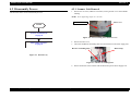
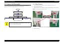
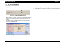
4.2 Disassembly Process
The flowchart below shows Disassembly Process
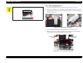
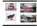
4.2.1 Scanner Unit Removal
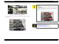
1.
Remove the one screw (CBP-Tite 3x10 F/Zn) securing the FFC Cover to the Middle
Housing.
NOTE: Screw tightening torque: 0.5 -0.7 Nm
CBP-Tite 3x10
FFC Cover
START
“Scanner Unit Removal”
on page 38
Figure 4-2. Screw securing the Connector Cover
“Disassembly of Printer”
on page 44
2.
Remove the FFC Cover.
3.
Disconnect the Harness Grounding Plate from the terminals on the Power Supply Unit.
Harness Grounding Plate
Mini Clamp
Figure 4-1. Flowchart (1)
Figure 4-3. Harness Grounding Plate
4.
Disassembly and Assembly
Release the harness of the Scanner from the Mini Clamp on the Power Supply Unit.
Disassembly Process
38
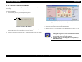
EPSON Stylus CX3100/3200
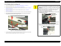
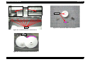
5.
Revision A
Using tweezers or the like, disengage the upper and lower hooks on the Harness
Fastening Plate which retain the Harness Fastening Plate to the Shield Cover for
the Main Board.
NOTE: Screw tightening torque: 0.5-0.7 Nm
CBP-Tite 3x10 F/Ni
Harness Fastening Plate
Figure 4-6. Screws securing the Scanner Unit
10. Remove the Scanner Unit upward.
Figure 4-4. Harness Fastening Plate
6.
Remove the Ferrite Core from the Shield Cover for the Main Board.
C A U T IO N
Ferrite Core
When removing the Scanner Unit, take care not to damage the
harness.
Figure 4-5. Ferrite Core
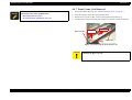
7.
Disconnect the four lines of harness of the Scanner Unit from the Main Board.
CCD harness:
CN1
HP detector harness:
CN2
Panel harness:
CN6
Motor harness:
CN7
8.
Remove the Ferrite Cores from the CCD harness and Panel harness.
9.
Remove the two (right and left) screws (CBP-Tite 3x10 F/Ni) securing the Scanner
Unit to the Middle Housing.
Disassembly and Assembly
Disassembly Process
39
EPSON Stylus CX3100/3200
Revision A
4.3.1 Hinge Removal
4.3 Scanner Unit Disassembly
This section describes the disassembly procedure for the scanner unit. Figure 4-7
shows the disassembly procedure flowchart for the scanner unit.
START
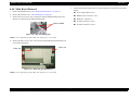
1.
Remove the scanner unit. (Refer to “Scanner Unit Removal” on page 38)
2.
Remove the document cover.
3.
Remove the four screws (CBP-Tite 3x10 F/Zn) securing the hinge to the scanner unit.
NOTE: Screw tightening torque: 0.5-0.7 Nm
Hinge Removal
Upper Housing
Removal
CBP-Tite 3x10 F/Zn
Motor Unit Removal
CCD Module Removal
Panel Circuit Board
Removal
Figure 4-7. Flowchart (2)
C A U T IO N
Perform disassembly and assembly of the scanner unit in an
environment free from dust. You are advised to work in a clean
room or on a clean bench, if possible.
Figure 4-8. Screws securing the Hinge
4.
Disassembly and Assembly
Remove the hinge.
Scanner Unit Disassembly
40
EPSON Stylus CX3100/3200
Revision A
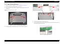
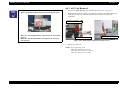
4.3.2 Upper Housing Removal
Hook
1.
Remove the scanner unit. (Refer to “Scanner Unit Removal” on page 38)
2.
Remove the hinge. (See “Hinge Removal” on page 40)
3.
Remove the two screws (CCP-Tite 3x8 F/Zb) securing the upper housing to the
scanner unit.
NOTE: Screw tightening torque: TBD
CCP-Tite 3x8 F/Zn
Figure 4-10. Hook Position
5.
Open the upper housing by lifting it from the rear.
6.
Insert your hand through the opening and disconnect the harness for the panel from the
connector on the panel circuit board.
Figure 4-9. Screws securing the Upper Housing
4.
Disengage the two hooks fastening the upper housing and lower housing.
Figure 4-11. Harness Disconnection
Disassembly and Assembly
Scanner Unit Disassembly
41
EPSON Stylus CX3100/3200
Revision A
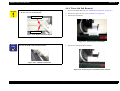
4.3.3 Motor Unit Removal
1.
Remove the scanner unit. (Refer to “Scanner Unit Removal” on page 38)
2.
Remove the hinge. (See “Hinge Removal” on page 40)
3.
Remove the upper housing. (See “Upper Housing Removal” on page 41)
4.
Disconnect the motor harness from the lower housing.
CCP-Tite 3x8F/Zn
Figure 4-14. Screws securing the Motor Unit
7.
C A U T IO N
Figure 4-12. Motor Harness
5.
Remove the motor unit.
Lead the harness of the motor along the groove in the lower
housing without floating.
Loosen the timing belt by pushing the driven pulley and remove the timing belt.
Figure 4-13. Driven Pulley for Timing Belt
6.
Remove the three screws (CCP-Tite 3x8 F/Zb) securing the motor bracket to the lower
housing.
NOTE: Screw tightening torque: TBD
Disassembly and Assembly
Scanner Unit Disassembly
42
EPSON Stylus CX3100/3200
Revision A
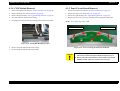
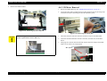
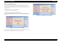
4.3.4 CCD Module Removal
4.3.5 Panel Circuit Board Removal
1.
Remove the scanner unit. (Refer to “Scanner Unit Removal” on page 38)
1.
Remove the scanner unit. (Refer to “Scanner Unit Removal” on page 38)
2.
Remove the hinge. (See “Hinge Removal” on page 40)
2.
Remove the hinge. (See “Hinge Removal” on page 40)
3.
Remove the upper housing. (See “Upper Housing Removal” on page 41)
3.
Remove the upper housing. (See “Upper Housing Removal” on page 41)
4.
Disconnect the FFC from the lower housing.
4.
Remove the five screws (CCP-Tite 3x6 F/Zb) securing the panel circuit board.
5.
Disengage the timing belt from the retaining portion of the CCD module.
NOTE: Screw tightening torque: TBD
CCP-Tite 3x8F/Zn
CCP-Tite 3x8F/Zn
Figure 4-15. Timing Belt Retaining Portion
6.
Remove the guide shaft from the lower housing.
7.
Remove the guide shaft from the CCD module.
Figure 4-16. Screws securing the Panel Circuit Board
C A U T IO N
When installing the panel circuit board, take care that no dust
enters between the LCD panel and the transparent cover.
Do not touch the switch contacts on the panel circuit board
with bare hand; otherwise, contact error can occur.
Disassembly and Assembly
Scanner Unit Disassembly
43
EPSON Stylus CX3100/3200
Revision A
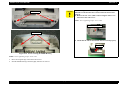
4.4.1 Middle Housing Removal
4.4 Disassembly of Printer
This section describes the disassembly procedure for the printer of Stylus CX3100/
3200. Figure 4-17 below shows the flowchart for disassembly procedure.
START
1.
Remove the scanner unit. (Refer to “Scanner Unit Removal” on page 38)
2.
Remove the three screws (CBP-Tite 3x10 F/Ni) securing the Front Housing to the
Middle Housing.
NOTE: Screw tightening torque: 0.5-0.7 Nm
“Middle Housing Removal”
on page 44
Front Housing
“Print Head Removal”
on page 46
“Holder Shaft Unit Removal”
on page 52
CBP-Tite 3x10
“Front Frame Unit Removal”
on page 53
Figure 4-18. Screws securing the Front Housing
“ASF Unit Removal”
on page 48
“CR Motor Removal”
on page 50
“Main Board Removal”
on page 54
“Waste Ink Pad Removal”
on page 49
3.
Remove the Front Housing.
4.
Remove the four screws (CBP 3x10 F/Zn) securing the Middle Housing to the Porous
Pad Tray.
“Power Unit Removal”
on page 56
Figure 4-17. Flowchart (3)
Disassembly and Assembly
Disassembly of Printer
44
EPSON Stylus CX3100/3200
Revision A
CBP 3x10
C A U T IO N
After installing the Middle Housing, remove the Tube Cover once
and make certain that the tube is inserted into the Porous Pad
properly.
Remove the one screw (CBP 3x10) securing the Tube Cover
and remove the Tube Cover.
NOTE: Screw tightening torque: 0.5-0.7 Nm
Tube Cover
CBP 3x10
Check that the tube is inserted into the Porous Pad properly.
Tube
Figure 4-19. Screws securing the Middle Housing
NOTE: Screw tightening torque: 0.5-0.7 Nm
5.
Move the left guide edge of the ASF to the left end.
6.
Shift the Middle Housing rearward slightly and lift it for removal.
Disassembly and Assembly
Disassembly of Printer
45
EPSON Stylus CX3100/3200
Revision A
4.4.2 Print Head Removal
C A U T IO N
Set the Tube Holder and install the Tube Cover.
Tube Holder
1.
Remove the Middle Housing. (See “Middle Housing Removal” on page 44.)
2.
Remove the cartridge covers for the B&W and color cartridges from the Carriage Unit.
3.
Disengage the two hooks (at A and B) of the FFC Holder and remove the FFC Holder
from the Carriage Unit.
C
A
B
Figure 4-20. Removing the FFC Holder
4.
Take off the Head FFC from the holding portion (at C) of the Carriage Unit.
5.
Remove the two screws, namely, one C.B.P-Tite 3x8 F/Zn and one C.B.B-Tite W2
2.5x5 F/Zb, which secure the Print Head to the Carriage Unit.
C.B.P-Tite SCREW
3x8 F/Zn
C.B.B-Tite W2
2.5x5 F/Zb
Figure 4-21. Screws securing the Print Head
Disassembly and Assembly
Disassembly of Printer
46
EPSON Stylus CX3100/3200
6.
Remove the Print Head.
7.
Disconnect the Head FFC from the connector of the Print Head.
A D J U S T M E N T
R E Q U IR E D
Revision A
C H E C K
P O IN T
Once you have replaced the Print Head with a new one, make the
following adjustments:
(Refer to “Adjustment by Adjustment Program” on page 59)
Head ID Input
Installing the Print Head
1. Set the Head FFC in the holding portion (at C) of the Carriage
Unit. (See Figure 4-20, "Removing the FFC Holder", p. 46)
2. Make sure that the head grounding plate is installed on the
Carriage Unit properly.
Head positioning pin
Ink Charge
Bi-D Adjustment
Top Margin Adjustment
First Dot Position Adjustment
When you have removed once and then installed the Print Head,
make the following adjustments:
Head Cleaning
Bi-D Adjustment
Top Margin Adjustment
First Dot Position Adjustment
Head grounding plate
Figure 4-22. Head Mounting Position
3.
4.
Disassembly and Assembly
Disassembly of Printer
Install the Print Head so that the two holes are put properly on
the respective pins of the Carriage Unit. (See Figure 4-22,
"Head Mounting Position", p. 47)
Secure the Print Head with the one screw (C.B.P-Tite SCREW
3x8 F/Zn) and one screw (C.B.B.-Tite W2 2.5x5 F/Zb).
Screw tightening torque;
C.B.P-Tite 3x8 F/Zn:0.5-0.7Nm
C.B.B-Tite W2 2.5x5 F/Zb:0.15-0.25Nm
47
EPSON Stylus CX3100/3200
Revision A
4.4.3 ASF Unit Removal
C H E C K
P O IN T
Installing the FFC Holder
1.
Remove the Middle Housing. (See “Middle Housing Removal” on page 44.)
Make certain that the Head FFC has been installed properly.
2.
Remove the three screws, namely, one C.B.P-Tite 3x6 F/Zn, one C.B.S-Tite(P4) 3x6
F/Zn and one C.B.P-Tite 3x8 F/Zn, which secure the ASF Unit to the printer
mechanism.
C.B.P-Tite 3x8 F/Zn
Figure 4-23. Installing the Head FFC
Make sure that the Head FFC is connected to the Print Head
C.B.S-Tite 3x6 F/Zn
properly.
Make sure that the FFC Holder is installed on the Carriage
Unit properly.
C.B.S-Tite 3x6 F/Zn
Figure 4-24. Removing the ASF Unit Securing Screws
3.
Remove the ASF Unit.
NOTE: Screw tightening torque
C.B.P-Tite 3x8 F/Zn:0.5-0.7 Nm
C.B.S-Tite(P4) 3x6 F/Zn: 0.7-0.9 Nm
C.B.P-Tite 3x8 F/Zn: 0.7-0.9 Nm
Disassembly and Assembly
Disassembly of Printer
48
EPSON Stylus CX3100/3200
Revision A
4.4.4 Waste Ink Pad Removal
C A U T IO N
Do not touch the LD Pad or Hopper Pad of the ASF Unit.
Do not reuse any scratched pad.
Hopper Pad
1.
Remove the Middle Housing. (See “Middle Housing Removal” on page 44.)
2.
Remove the ASF Unit. (See “ASF Unit Removal” on page 48)
3.
Remove the Tube Holder.
LD Pad
Figure 4-25. Hopper Pad and LD Pad
Figure 4-27. Removing the Tube Holder
C H E C K
P O IN T
When installing the ASF Unit, the flat surface of the LD Roller
must face the inside of the Mechanism Unit.
4.
Remove the Tube Holder Waste Ink Pad.
Figure 4-26. LD Roller Installation
Figure 4-28. Removing the Tube Holder Waste Ink Pad
Disassembly and Assembly
Disassembly of Printer
49
EPSON Stylus CX3100/3200
5.
Revision A
4.4.5 CR Motor Removal
Remove the Waste Ink Pad.
1.
Remove the Middle Housing. (See “Middle Housing Removal” on page 44.)
2.
Loosen the timing belt by pushing the driven pulley holder at the left end of the printer
mechanism and remove the timing belt from the CR Motor pinion.
Figure 4-29. Removing the Waste Ink Pad
Figure 4-30. Removing the Timing Belt
C A U T IO N
When installing the Tube Holder Waste Ink Pad, make certain that
the tube is placed in the Porous Pad Tray.
3.
Disconnect the motor lead wires from the connector (CN14) on the Main Board.
4.
Disconnect the Print Head FFC from the connectors (CN8 and CN9) on the Main
Board.
5.
Disengage the one hook with which the FFC Spacer fastens the clamp to the Holder
Shaft Unit and remove the clamp upward.
FFC Spacer
Hook
Figure 4-31. Removing the FFC Clamp
Disassembly and Assembly
Disassembly of Printer
50
EPSON Stylus CX3100/3200
6.
Revision A
Release the motor lead wires from the fastening portion of the Holder Shaft Unit.
C A U T IO N
When installing the CR Motor, pay attention to the following
particulars:
Connect the motor lead wires to the connector (CN14) on the
Main Board.
Tighten the hexagon nuts in the numeric order shown below.
NOTE: Screw tightening torque: 0.5-0.7Nm
1
4
Figure 4-32. Releasing the Motor Lead Wires
7.
While holding the motor, remove the four hexagon nuts (M3) securing the motor to the
mechanism.
3
2
Check that the motor is secured properly.
A D J U S T M E N T
R E Q U IR E D
Once the CR Motor has been removed or replaced, make
adjustments in the order specified below:
1. Bi-D Adjustment (See p.63)
2. First Dot Position Adjustment (See p.67)
CR
Figure 4-33. Removing the CR Motor
Disassembly and Assembly
Disassembly of Printer
51
EPSON Stylus CX3100/3200
Revision A
4.4.6 Holder Shaft Unit Removal
1.
Remove the Middle Housing. (See “Middle Housing Removal” on page 44.)
2.
Remove the ASF Unit. (See “ASF Unit Removal” on page 48)
3.
Remove the FFC Spacer and Head FFC from the Holder Shaft Unit. (See “CR Motor
Removal” on page 50)
4.
Release the CR Motor lead wires from the Holder Shaft Unit. (See “CR Motor
Removal” on page 50)
5.
Disconnect the HP/PE sensor lead wires from the connector (CN4) on the Main Board.
6.
Disengage the two hooks fastening the Holder Shaft Unit to the printer mechanism
(step 1) and lift the holder upward slightly (step 2).
C A U T IO N
Do not touch the LD Roller.
Ensure that the Head FFC, the CR Motor lead wires and the
HP/PE sensor lead wires are fastened to the Holder Shaft Unit
properly.
Ensure that the Head FFC, the CR Motor lead wires and the
HP/PE sensor lead wires are connected to the respective
connectors on the Main Board properly.
Take care not to damage the teeth of the Spur Gear 35.2 and
combination gear 16, 32.
Spur Gear 35.2
theしunit
slightly (step
2) ッ プ 2)
ユニ ッ Lift
ト を少
持ち上げる
( ステ
Combination Gear 16, 32
Ensure that the tip of the changeover lever inside the pump
unit is positioned inside the printer mechanism.
Push the pump unit to the right
(step 3)
Changeover Lever
Unhook (step 1)
Figure 4-34. Removing the Holder Shaft Unit
7.
Push the pump unit to the right and disengage the pump unit from the pin on the Holder
Shaft Unit and lift the Holder Shaft Unit for its removal (step 3).
Disassembly and Assembly
Disassembly of Printer
52
EPSON Stylus CX3100/3200
Revision A
4.4.7 Front Frame Unit Removal
A D J U S T M E N T
R E Q U IR E D
Once the Holder Shaft Unit has been removed or replaced, make
adjustments in the order specified below:
1. Bi-D Adjustment (See p.63)
2. First Dot Position Adjustment (See p.67)
1.
Remove the Middle Housing. (See “Middle Housing Removal” on page 44.)
2.
Move the Carriage Unit to the home position by hand.
3.
Remove the two screws (C.B.S. 3x6 F/Zn) securing the Front Frame Unit.
4.
Lift the left end of the Front Frame Unit and move it to the left carefully for removal.
Step 2
Spur Gear 60
Step 1
C.B.S. 3x6
Figure 4-35. Removing the Front Frame Unit
Disassembly and Assembly
C A U T IO N
When removing and installing the Front Frame Unit, take care not
to damage the Spur Gear 60.
Disassembly of Printer
53
EPSON Stylus CX3100/3200
Revision A
4.4.8 Main Board Removal
5.
1.
Remove the Middle Housing. (See “Middle Housing Removal” on page 44.)
2.
Remove the ASF Unit. (See “ASF Unit Removal” on page 48)
3.
Remove the two screws (C.B.S. 3x6 F/Zn) securing the M/B Grounding Plate to the
Shield Cover and remove the M/B Grounding Plate.
Disconnect the following lead wires from the respective connectors on the Main
Board.
Power Supply Board: CN5
HP/PE sensor lead wires: CN4
Head FFC: CN8 and 9
PF Motor lead wires: CN13
C.B.S. 3x6 F/Zn
PF Motor lead wires: CN14
Figure 4-36. M/B Grounding Plate
NOTE: Screw tightening torque;C.B.S. 3x6, F/Zn (2 pcs.): 0.5-0.7Nm
4.
Remove the three screws (C.B.S. 3x6 F/Zn) securing the Main Board and Shield Cover
to the Printer Mechanism.
C.B.S. 3x6
C.B.S. 3x6
Figure 4-37. Removing the Main Board
NOTE: Screw tightening torque;C.B.S. 3x6, F/Zn (3 pcs.): 0.5-0.7Nm
Disassembly and Assembly
Disassembly of Printer
54
EPSON Stylus CX3100/3200
C A U T IO N
Revision A
Install the Shield Cover on the Main Board so that the USB
connector is held in the Shield Cover. (See below)
A D J U S T M E N T
R E Q U IR E D
Once you have replaced the Main Board with a new one, make the
following adjustments:
Destination Setting (EEPROM Initialization) (See p.61)
Head ID Input (See p.62)
Bi-D Adjustment (See p.63)
USB ID Input (See p.65)
Top Margin Adjustment (See p.66)
First Dot Position Adjustment (See p.67)
A D J U S T M E N T
R E Q U IR E D
When you have removed once and installed the Main Board, make
the following adjustments:
Bi-D Adjustment (See p.63)
There may be cases where the contents of EEPROM on the Main
Board can be read, for example, when only the motor driver has
broken down. In such cases, to shorten repair time, you can back
up only the adjusted values by executing the following operation
and download the adjusted values onto the newly installed Main
Board.
EEPROM Data Backup (See p.70)
Connect the power supply cable on the secondary side to the
Main Board so that the blue-band cable end is positioned at pin
1 as shown below.
When installing the Main Board in the Printer Mechanism
Unit, engage the Main Board with the hooks on the Mechanism
Unit as shown below.
Disassembly and Assembly
Disassembly of Printer
55
EPSON Stylus CX3100/3200
Revision A
4.4.9 Power Unit Removal
1.
Remove the Middle Housing. (See “Middle Housing Removal” on page 44.)
2.
Remove the ASF Unit. (See “ASF Unit Removal” on page 48)
3.
Remove the Main Board. (See “Main Board Removal” on page 54)
4.
Remove the three screws, namely, one C.B.S. 3x6 F/Zn and two C.B.P-TITE 3x8 F/Zn,
securing the Power Supply Unit to the Porous Pad Tray.
C.B.P-TITE 3x8 F/Zn
C.B.S. 3x6 F/Zn
Hook
C.B.P-TITE 3x8
F/Zn
Power Unit
Figure 4-38. Power Supply Unit Removal
5.
Remove the Power Supply Unit by detouring the hook on the Porous Pad Tray.
NOTE: Screw tightening torque: C.B.P-TITE 3x8 F/Zn (2 pcs.): 0.5-0.7Nm
C.B.S. 3x6, F/Zn (1 pc.): 0.5-0.7Nm
Disassembly and Assembly
Disassembly of Printer
56
CHAPTER
5
ADJUSTMENT
EPSON Stylus CX3100/3200
Revision A
5.1 Overview
This Chapter describes the necessary adjustment items and adjustment procedures for
applicable Unit / Parts.
5.1.1 Printer Mechanism Adjustment Items
This section shows details of each Adjustment Process according to Adjustment
Program.
Adjustment Information for each Printer Mechanism needs to be set for this product in
order to maintain reliable printing function and print quality for each printer
mechanism. Accordingly, once the Printer Mechanism, Main Board or Print Head has
been replaced, it is necessary to set and save the correct information of the mechanism
into the Main Board by using the Adjustment Program.
The adjustment items for this product are as indicated below. When performing any of
these adjustments, be sure to execute all the related items so that this product operates
normally.
C A U T IO N
During execution of the Adjustment Program, be sure to turn off
the power to the printer when parts are to be removed and
installed.
Table 5-1. Mechanism Adjustment Items
1
2
3
4
5
6
Adjust contents
Firmware
upload
Head ID
input
Ink filling
Bi-D
adjust
USB-ID
input
Protect
counter reset
Head removal
Not
applicable
Not
applicable
Not
applicable
c
Not
applicable
Not applicable
Head replace
Not
applicable
c
d
e
Not
applicable
Not applicable
Main board
replacement
c
c
Not
applicable
d
e
Not applicable
CR unit replace/
removal
Not
applicable
Not
applicable
Not
applicable
d
Not
applicable
Not applicable
CR motor replace
Not
applicable
Not
applicable
Not
applicable
c
Not
applicable
Not applicable
Printer mechanism
replace
Not
applicable
c
d
e
Not
applicable
Not applicable
Waste ink porous
pad replace
Not
applicable
Not
applicable
Not
applicable
Not
applicable
Not
applicable
c
Note 1: { mark shows that adjustment work is necessary. The circled figures indicate the order
in which the adjustment work is to be carried out.
2: The following adjustment is not necessary for this product.
•Head Slanting Adjustment
Adjustment
Overview
58
EPSON Stylus CX3100/3200
Revision A
5.1.2 Dedicated Tools
5.2 Adjustment by Adjustment Program
Table 5-2 shows the dedicated tools for executing the adjustment items listed above.
Table 5-2. Dedicated Tools
This machinery is adjusted by using the dedicated adjustment program. Adjusted
compensation values are written into EEPROM on the Main Board.
1
Adjustment Program
Mechanism setting
Dedicated program
2
EFlash3.exe
Firmware upload
Dedicated program
This Program is intended to absorb the unevenness of features of individual Printer
Mechanisms and ensure a satisfactory print quality. When the Printer Mechanism, Print
Head or Main Board has been replaced, it is necessary to write the correct
compensation values by using this Adjustment Program.
3
RMDEV. exe
ROM rewriting limitation
invalidation program
Dedicated program
5.2.1 Adjustment Program Installation
No.
Name
Adjustment Items
Description / Specification
1.
Insert the floppy disk storing the Adjustment Program into the floppy disk drive.
2.
Open the floppy disk holder and copy “Adjustment Program” onto the desk top.
3.
Execute the Adjustment Program.
C A U T IO N
Adjustment
Before installing this program, make sure that the USB Driver
has been installed on the PC.
This program is exclusive for use on windows98/Me. This does
not operate on DOS or Windows3.x or NT.
Do not start the program before connecting the USB cable to
Stylus CX3100/3200.
The Adjustment Program comes with some sub files which
appear by decompressing the compressed file. Be sure to store
the sub files in the same holder where the Adjustment Program
is stored.
Adjustment by Adjustment Program
59
EPSON Stylus CX3100/3200
Revision A
5.2.2 Adjustment Program Start
1.
From the menu, select the item for which the adjustment is to be made. (Refer to Table
5-3)
When the Adjustment Program is started, the screen as shown in Figure 5-1 is
displayed. Select the Model Name.
Table 5-3. Adjustment Item Menu
Menu
Adjustment
Adjustment Item for which setting can be made
Destination Setting (EEPROM Initialization) (p.61)
Head ID Input (p.62)
Bi-D Adjustment (p.63)
USB ID Input (p.65)
Top Margin Adjustment (p.66)
First Dot Position Adjustment (p.67)
Maintenance
Head Cleaning (p.68)
Ink Charge (p.68)
Charging the transportation liquid
Protection Counter (p.69)
EEPROM Data Backup (p.70)
Figure 5-1. Model Name Port Number Selection
2.
Select the destination of Stylus CX3100/3200.
3.
Click the [OK] button.
C H E C K
P O IN T
Check pattern printing
A4 Plain Paper Printing (p.70)
Additional function
EEPROM Data (p.71)
Upon completion of selection of model and destination, the screen as shown in Figure
5-2 is displayed.
While Stylus CX3100/3200 is warming up (Power LED is
blinking), the program can not be executed (communication
error occurs). Execute the program after making certain that
the Power LED of the printer is lit.
Figure 5-2. Adjustment Program
Adjustment
Adjustment by Adjustment Program
60
EPSON Stylus CX3100/3200
Revision A
5.2.3 Destination Setting (EEPROM Initialization)
The Adjustment Program has the following buttons.
Quit
Click the [Quit] button, and a menu screen to select [Quit] or [Next] will be
displayed. Clicking the [Quit] button on that menu screen will complete the
adjustment and close the program. Clicking the [Next] button will return the
display to the screen for selecting a Model Name and Destination.
When the Main Board of this machinery has been replaced with a new one, enter the
initial setting values in EEPROM with this Adjustment Item.
Figure 5-3. EEPROM Initialization
Click the [OK] button, and the message indicating that the initial values of Stylus
CX3100/3200 have been written will appear in the lower center of the screen.
Click the [Check] button, and you can check the current setting of printer destination.
Adjustment
Adjustment by Adjustment Program
61
EPSON Stylus CX3100/3200
Revision A
5.2.4 Head ID Input
With this item, you can write the Head ID in EEPROM and check the current set value.
This adjustment compensates for the unevenness of ink eject volume and ensure
satisfactory print quality. Unless the correct ID is input, unevenness in print density can
occur.
This adjustment is required on any of the following occasions.
When the Print Head has been replaced with a new one
When the Main Board has been replaced with a new one
When the Printer Mechanism has been replaced with a new one
Figure 5-4. Head ID Adjustment Items
1.
Click the item for which the adjustment is to be made and click the [OK] button.
Select the [Check present data], and the Head ID currently stored in EEPROM will
be indicated at the lower center of the screen.
Figure 5-5. Head ID Input
2.
Adjustment
Check the 11-digit ID written on the Printer Head and input it. Upon completion of
input, click the [OK] button. For returning to previous screen, click the [Previous]
button. The input values are indicated for the respective input items at “Adjusted
items list”.
Adjustment by Adjustment Program
62
EPSON Stylus CX3100/3200
Revision A
5.2.5 Bi-D Adjustment
C A U T IO N
For Head ID, use the 11-digit character string described in the
Print Head. Example: T17R4TUTTTG
This adjustment corrects the deviation of printing timing for bidirectional printing
which can occur due to variation of assembly precision/component parts of the Printer
Mechanism. In this adjustment, print the Bi-D Pattern and adjust so that the pattern can
be correctly printed. And the current setting value can be checked. Carry out this
adjustment in the sequence as Printing of pattern → Checking → Adjustment →
Printing → Checking. This adjustment is necessary when any of the following works
has been performed:
Printer Mechanism replacement
Main Board replacement
CR Motor replacement
Carriage Assembly replacement
Printer head replacement
Figure 5-6. Bi-D Adjustment Item
Adjustment
Adjustment by Adjustment Program
63
EPSON Stylus CX3100/3200
Revision A
1.
Click the item for which the adjustment is to be made and click the [OK] button.
When you select “Printing the Bi-D adjustment pattern”, you can print the pattern.
When “Checking present Bi-D parameter” is selected, the set value is indicated at
the lower center of the screen. When you select “Input Bi-Directional adjustment
value”, you can input the adjusted values.
2.
From the printed Bi-D adjustment pattern, judge which vertical line corresponding
to which compensation value for each mode is straight.
Figure 5-8. Input Bi-Directional Adjustment Value
4.
Check the item for which the adjustment is to be made. The input value is
indicated in [Adjusted items] at the right side of the screen.
5.
By repeating steps 1 to 4 above, make adjustment to minimize the deviation of
bidirectional printing timing.
Figure 5-7. Bi-D Adjustment Pattern
3.
If adjustment is necessary, select [Bi-D Adjustment] and input the compensation
values at the relevant points in each mode. Adjusted values can be input for each
mode.
Adjustment
Adjustment by Adjustment Program
64
EPSON Stylus CX3100/3200
Revision A
5.2.6 USB ID Input
2.
Stylus CX3100/3200 is equipped with the USB Interface as standard. As the USB Port
Driver controls the device through the USB ID on Windows98 or iMac, a proper USB
ID is assigned to this product. Since the USB ID is stored in EEPROM on the Main
Board, the USB ID needs to be input again when the Main Board has been replaced
with a new one. The USB ID is an 18-digit alphanumeric character string specific to
the machine, and recorded at the particular address on EEPROM. The USB ID is
determined at the factory as follows:
Read 10 digits serial number from manufacture plate on the back of Stylus
CX3100/3200 and input it and click the [OK] button. New USB ID is input to
EEPROM.
Manufacture process line No. (3 digits)
PC No. (2 digits)
Date (12 digits) -The built-in time data of the PC is used.
“0” (1 digit)
In repair, the 10-digit product serial number is used as the 10 digits of the new USB ID,
and the new USB ID is completed with an 8-digit character string which is produced by
Adjustment Program and automatically added to the serial number. Then input the new
USB ID in EEPROM on the new Main Board.
1.
Click the item for which the adjustment is to be made and click the [OK] button.
When you select [USB ID], the set value is indicated at the lower center of the
screen.
When you select [USB ID Change], the screen as shown Figure 5-9 below is
displayed and the Head ID can be input.
Figure 5-9. USB ID Input
Adjustment
Adjustment by Adjustment Program
65
EPSON Stylus CX3100/3200
Revision A
5.2.7 Top Margin Adjustment
4.
Select the desired one of the "+", "0" and "-" buttons and press the "OK" button for
setting. Select "+" to enlarge the margin or "-" to lessen it. Three levels are
available for selection.
5.
Print the pattern again and check the top margin.
6.
Determine the setting value so that the top margin as close to the specified value as
possible.
By this adjustment, set the value of top margin.
1.
By pressing the [Print] button, print the adjustment pattern on PPC55kg paper.
Figure 5-10. Top Margin Adjustment Pattern
2.
Measure the distance (top margin: specified value 3 mm) from the front end of the
paper with the print pattern to the horizontal bar representing the printing start
position.
3.
If the measured value is deviated from the specified value, select the [Adjust]
button to enter the adjustment mode.
Figure 5-11. Adjustment Mode
Adjustment
Adjustment by Adjustment Program
66
EPSON Stylus CX3100/3200
Revision A
5.2.8 First Dot Position Adjustment
This adjustment corrects the left margin (Print start position) for post card printing and
A4 printing.
The value indicated at the center of the adjustment window is the current value
recorded in EEPROM.
1.
Press the [Print] button to print the adjustment pattern.
Figure 5-13. First Dot Position Adjustment Mode
Figure 5-12. First Dot Position
2.
Measure the distance (left margin) from the left edge of the paper for the print
pattern to the vertical line representing the print start position.
3.
Change the setting by pressing the “∆” or “∇” button beside or under the current
value.
Adjustment
4.
Press the [Write] button to set the adjustment value.
5.
Press the [Print] button to print the adjustment pattern.
6.
Repeat steps 2 to 5 above and adjust so that the left margin will be 3+/-1.5 mm.
C H E C K
P O IN T
While Stylus CX3100/3200 is warming up (Power LED is
blinking), the program can not be executed (communication
error occurs). Execute the program after making certain that
the Power LED of the printer has turned on.
Each input of one step will change the first dot position by 1/
2880 inch (0.009 mm).
Adjustment by Adjustment Program
67
EPSON Stylus CX3100/3200
Revision A
5.2.9 Head Cleaning
5.2.10 Ink Charge
You can execute more intensive cleaning than Head Cleaning, which is carried out by
selecting it in the menu on the Operation Panel. This function releases the Head Nozzle
from clogging which can cause dot missing.
When the Head or Printer Mechanism has been replaced, ink is not available in the ink
route just after its installation, thus ink needs to be filled.
NOTE: The following amount of ink will be consumed every time head cleaning
is executed:
Black
: 1/9 of unused ink cartridge
Color
: 1/18 of unused ink cartridge
When the following work has been performed, ink must be initially filled by executing
this item.
Printer Mechanism replacement
Printer Head replacement
NOTE: The following amount of ink will be consumed every time ink charge is
executed:
Click the [OK] button, and head cleaning will be executed.
C A U T IO N
Adjustment
Black
: 1/3 of unused ink cartridge
Color
: 1/7 of unused ink cartridge
If the nozzle is not released from clogging even by this cleaning,
execute initial ink filling. (Refer to “Ink Charge” on page -68)
Adjustment by Adjustment Program
.
68
EPSON Stylus CX3100/3200
Revision A
5.2.11 Protection Counter
This counter controls total ink eject volume and displays error status if the volume
exceeds the set value, displaying the waste ink overflow indication (printer error
indication and Error LED blinking.). By selecting this item, you can check or clear the
protection counter.
This operation is necessary after the following work.
Waste Ink Porous Pad replacement
Click the item to be executed and click the [OK] button.
When you select “Checking the present counter” on the screen as shown in Figure
5-14 and click the [OK] button, the count value will be indicated at the lower center of
the screen.
Figure 5-15. Clearing the Protection Counter
Figure 5-14. Protection Counter Reading
When you select “Clearing the protection counter”, the screen as shown in Figure 5-15
is displayed. Click the [OK] button to clear the protection counter.
Adjustment
Adjustment by Adjustment Program
69
EPSON Stylus CX3100/3200
Revision A
5.2.12 EEPROM Data Backup
5.2.13 Check Pattern Printing
This function is to back up data and write it on the new board when the Main Board has
been replaced with a new one. For example, with the conventional models, whenever
the Main Board is replaced, the ink counter is automatically reset and can not be
handed down to the new board. With this function, however, the original data can be
used with the new board, thus the adjustment process can be shortened.
This function is to print several patterns on paper. By this printing, you can check the
functions of Stylus CX3100/3200.
5.2.13.1 A4 Plain Paper Printing
A4 paper is used for printing of check patterns. Before executing printing, set A4 paper
in the ASF and click the [OK] button. Then, printing of Check Patterns will start.
Data to be backed up are as follows.
Protection counter
Each color ink consumption counter
Bi-D adjustment values
First dot position adjusted value
Head ID
USB ID
Market ID (Destination set value)
1.
To execute data backup, press the [OK] button. Data will be read from EEPROM
2.
When reading data from EEPROM, the following indication appears.
3.
Replace the Main Board and turn on the power to the printer.
4.
After confirming that Stylus CX3100/3200 has finished warming up, press the
[OK] button. Press the [Cancel] button to discontinue backup.
C H E C K
P O IN T
While Stylus CX3100/3200 is warming up (Power LED is
blinking), the program can not be executed (communication
error occurs). Execute the program after making certain that
the Power LED of the printer has turned on.
Figure 5-16. A4 Plain Paper Printing
Check the printed patterns. If there is any problem, make adjustment for the relevant
items by using the program again.
Adjustment
Adjustment by Adjustment Program
70
EPSON Stylus CX3100/3200
Revision A
5.2.14 EEPROM Data
With this function, even in error status, you can check the data in EEPROM or write
data in it by directly designating addresses in EEPROM. (But if the CPU of the Main
Logic Circuit, I/F Receiver, RAM or EEPROM is broken down, this function can not
be used.)
Check “EEPROM data” in the additional function menu, and the following menu will
be indicated.
The EEPROM data function has the following two functions:
Checking the data in EEPROM
You can check the data in EEPROM in the range of designated addresses.
Designate the addresses at which you want to check the data and click the [OK]
button, and the data in EEPROM will be read from the printer and displayed on the
screen.
Inputting data in EEPROM
You can write data to change the value at the designated address in EEPROM.
But, use this function on special occasions only. If data is changed carelessly,
trouble can occur.
Adjustment
Adjustment by Adjustment Program
71
EPSON Stylus CX3100/3200
Revision A
5.3 Firmware Uploading
C A U T IO N
The firmware for Stylus CX3100/3200 is stored in flash ROM on the C497MAIN
Board. Therefore, firmware can be reinstalled by uploading it from the personal
computer without disassembling the machine. This section describes the procedure for
uploading firmware.
C A U T IO N
If the error display as shown below has appeared, take the
following actions:
Change the underlined model name indicated below in
“C497_Bessho.inf”, which is contained in the same holder as
the upload program is contained, to the model name for which
firmware is now to be uploaded.
The personal computer to be used for installing firmware must
be equipped with Windows98, Me, 2000 or later operating
system, which permits use of the USB interface.
The personal computer must have the TWAIN 5 and EFlash3
installed beforehand.
1.
Connect the Stylus CX3100/3200 to the personal computer with the USB cable.
2.
Turn on the power to the personal computer and Stylus CX3100/3200.
3.
Double-click the EFlash3 icon to start the EFlash3 program.
strTarget1=EPSON CC-550L
strTarget2=EPSON STYLUS CX3200
strTarget3=EPSON CC-570L
If the error recurs even after above change, replace the PC
with another one and check to see if the error is cleared.
Cancel
Figure 5-18. Search for Firmware
Figure 5-17. EFlash3 Starting Screen
4.
Click the “(N) >” button to proceed with the program on the screen, and the screen
as shown below will be displayed.
Adjustment
5.
Make a search for firmware by means of the “>>” button.
Firmware Uploading
72
EPSON Stylus CX3100/3200
Revision A
3.
C A U T IO N
1.
Firmware is available in the Motorola format (with the extension
as *.MOT).
If the firmware file has a different extension, rewrite it to MOT.
Upon successful completion of firmware transfer, the window as shown below
will be displayed on the EFlash3 screen. The power to Stylus CX3100/3200 will
automatically be turned off. Once power is turned on next time, Stylus CX3100/
3200 will operate on the new firmware.
When the menu as shown below has been displayed, click the “Open” button to
open the selected file.
Figure 5-21. Upload Completion
C A U T IO N
Figure 5-19. Firmware File Selection
2.
Press the “>” button on EFlash3, and firmware will be transferred.
8
With a personal computer on an operating system of
Windows98 Second edition, the number of times of writing in
ROM is limited to 10. To invalidate this limitation, decompress
all the files in the compressed file “Win98&98SE supplement
tool.zip” and execute the newly generated execution file
“RMDEV.exe”.
Figure 5-20. Firmware Transfer Start
Adjustment
Firmware Uploading
73
CHAPTER
6
MAINTENANCE
EPSON Stylus CX3100/3200
Revision A
6.1 Overview
6.1.2 Maintenance of the Scanner
This section describes maintenance work to maintain the functions and performance of
this product.
6.1.2.1 Lubrication Points of the Scanner (TBD)
6.1.1 Cleaning
When any part of the CR Unit of the scanner has been replaced or the sound of carriage
moving is loud, lubrication is necessary. Figure 6-1 and Figure 6-2 below indicate the
designated grease and lubrication points.
Clean if dirt is visible. As dirt on the glass for placing the document affects directly
image reading quality, clean the glass completely.
C A U T IO N
Table 6-1. Designated Grease
Never use chemical solvents, such as thinner or benzine, as they
Kind
Name
Parts Code
Supply Source
Grease
G-45
1033657
EPSON
may deform or deteriorate plastic and rubber products.
Table 6-2. Designated Lubrication Points
Be careful not to damage any components when you clean
Figure
inside the printer.
Do not scratch the surface of the PF roller assembly. Use a soft
brush to wipe off any dust. Use a soft cloth moistened with
alcohol to remove ink stain.
Do not use frequently the cleaning sheet included in the media.
It may damage the coated surface of the PF roller.
However, it is no problem to clean the surface of the ASF LD
roller by placing the adhesive surface of the cleaning sheet on
the ASF LD roller.
Lubrication Points
Lubrication
Figure 6-1
Scanner carriage guide shaft
C A U T IO N
If lubrication exceeds the designated volume, the mechanism may be
damaged or functions may be impaired. Be sure to apply the
designated volume of grease correctly.
Exterior parts
G-26
Figure 6-1. Lubrication Points of the Scanner
Use a clean soft cloth moistened with water and wipe off any dirt. If the exterior
parts are very dirty, use a cloth moistened with a neutral detergent to wipe it off.
Inside the printer
Use a vacuum cleaner to remove any paper dust.
Glass for placing the original document on
Remove dust or any paper with a clean dry cloth. If dirt is serious or foreign
material is adhering, wipe it off with a cloth moistened with a neutral detergent. If
a trace of wiping has remained, wipe the glass again with a dry clean cloth.
ASF LD Roller
If paper dust on the surface of the ASF LD Roller lowers the friction, place the
adhesive surface of the cleaning sheet included in the media on the surface of the
ASF roller and repeat paper loading from the ASF.
Maintenance
Overview
75
EPSON Stylus CX3100/3200
Revision A
6.1.3 Maintenance of the Printer
6.1.3.3 Lubrication Points of the Printer
If print irregularity (dot missing, white line, etc.) has occurred or the printer indicates
“Maintenance Error”, take the following actions to clear the error.
The kinds and volume of the oils and grease for lubrication of the Printer are
determined based on factory evaluation. Therefore, be sure to apply a specified volume
of the designated grease to each designated point for repair and maintenance of the
Printer. The designated grease and application points are indicated below.
6.1.3.1 Head Cleaning
The printer has a built-in head cleaning function, which is activated on the operation
panel. Confirm that the printer is in the stand-by state (the power indicator is not
blinking). Select “Head Cleaning” by means of the Menu buttons on the operation
panel and execute it, and the printer will start head cleaning.
C A U T IO N
6.1.3.2 Maintenance Error
Ink is used not only for printing but also for other operations, such as cleaning. During
such an operation, the printer wastes a certain amount of ink and drains it into the waste
ink pad, and the amount of the waste ink is counted.
Once the amount of waste ink reaches the predetermined limit, the printer indicates
“Maintenance Request” and the waste ink pad must be replaced.
Overflow Counter (Protection Counter) count up ≥ 23270
Time for replacing the Waste Ink Pad
Never use any oil or grease other than designated, since any
other oil or grease can badly affect the machine life or function
of the product or damage the mechanism.
As the volume of application is also designated based on
evaluation result, be sure to apply the designated volume of
grease correctly.
Table 6-3. Designated Lubricant
Kind
Name
Parts Code
Available from
Grease
G-46
1039172
EPSON
Grease
G-58
1082176
EPSON
When the total amount of waste ink reaches the predetermined limit, the printer
indicates “Maintenance Request”. (Refer to “TBD”). During repair operation,
check the overflow counter and the firmware version, selected code page and
nozzle check pattern.
If the ink counter value is close to its upper limit, notify your customer and
recommend that the waste ink pad is to be replaced. (If the waste ink pad is not
replaced at that time, “Maintenance Error” will occur just after the printer is
retuned to the customer.) Once you have the confirmation from the customer,
replace the waste ink pad.
Replacement procedure
Refer to “Waste Ink Pad Removal” on page 49
Treatment after replacement
Reset the Overflow counter (Protection counter). Turn on the power to the printer
and enter into the special menu (ordinary operation) and execute waste ink counter
reset menu or perform counter clear by the adjustment program. (Refer to
“Protection Counter” on page 69)
Maintenance
Overview
76
EPSON Stylus CX3100/3200
Revision A
Table 6-4. Designated Lubrication Points (continued)
Table 6-4. Designated Lubrication Points
Lubrication Points /
Amount of Application
Figure
Lubrication Points
Figure 6-2
Figure 6-3
• 4 positions on the periphery of
the CR guide shaft
Grease to be applied
• G-58
Amount of Application
• 100 mg in total (25 mg at each
position)
• Do not apply to any part of the carriage
unit other than specified.
• Use an injector to apply grease.
• Move the carriage unit from side to
side to spread the applied grease
evenly.
• After applying grease, check that the
carriage unit moves smoothly.
Lubrication Points
• Use an injector to apply grease.
• 4 positions in the grooves in
the driven pulley holder
Grease to be applied
• G-58
Amount of Application
• 1 mm in diameter x 1 mm in
length (at each position)
Lubrication Points
Figure 6-4,
Figure 6-5
Figure
Precautions
• Center area and notched
portion on the front frame
Grease to be applied
• G-58
Amount of Application
• Center area: 1 mm in diameter
x 300 mm in length
• Notched portion: 1 mm in
diameter x 20 mm in length
Maintenance
Lubrication Points /
Amount of Application
Lubrication Points
Figure 6-6
• Top of the paper eject roller (9
positions), and similar
positions after rotating the
roller rearward by 180 degrees
Grease to be applied
• G-46
Amount of Application
• Apply evenly with a brush.
Lubrication Points
Figure 6-7
• Use an injector to apply grease.
• Move the carriage unit from side to
side to spread the applied grease
evenly.
• Apply to the surface of top
teeth of the spur gear 60 and
then turn the gear M rearward
by 90 degrees
Grease to be applied
• G-58
Amount of Application
• 1 mm in diameter x 25-50 mm
in length
Lubrication Points
Figure 6-8
Overview
Precautions
• Apply the grease after replacement
with the after-sale service part.
• Use an injector to apply grease.
• Do not touch the surface to which the
grease has been applied.
• Apply the grease after replacement
with the after-sale service part.
• Use an injector to apply grease.
• Center on the driven pulley
shaft (1 position)
• Inner periphery of the hole in
the driven pulley (2 positions)
Grease to be applied
• G-58
Amount of Application
• Driven pulley shaft: 1 mm in
diameter x 20 mm in length
• Driven pulley hole: 1 mm in
diameter x 1 mm in length (at
each position)
77
EPSON Stylus CX3100/3200
Revision A
G-58
30 mm
G-58
Figure 6-2. Lubrication Points of the Printer 1
Figure 6-4. Lubrication Points of the Printer 3
20 mm
G-58
Figure 6-3. Lubrication Points of the Printer 2
G-58
Figure 6-5. Lubrication Points of the Printer 4
Maintenance
Overview
78
EPSON Stylus CX3100/3200
Revision A
G-46
G-58
G-46
Figure 6-8. Lubrication Points of the Printer 7
Figure 6-6. Lubrication Points of the Printer 5
G-58
Figure 6-7. Lubrication Points of the Printer 6
Maintenance
Overview
79
CHAPTER
7
APPENDIX
EPSON Stylus CX3100/3200
Revision A
7.1 Connectors
7.1.1 Connector Assignments
Figure below shows the connector assignments on the circuit boards of Stylus CX3100/
3200.
Figure 7-1. Connector Assignments of Circuit Boards
Appendix
Connectors
81
EPSON Stylus CX3100/3200
Revision A
7.2 Circuit Board Component Layout
Appendix
Circuit Board Component Layout
82
EPSON Stylus CX3100/3200
Revision A
7.3 Electric Circuit Diagrams
This section shows electric circuit diagrams of Stylus CX3100/3200. The electric
circuits of Stylus CX3100/3200 are provided on the following circuit boards:
C497MAIN Board
Printer circuit
B110MAIN Board
Scanner circuit
C497PSB Board
Power supply circuit
Appendix
Electric Circuit Diagrams
83
EPSON Stylus CX3100/3200
Revision A
7.4 Exploded Diagrams
Appendix
Exploded Diagrams
88
EPSON Stylus CX3100/3200
Revision A
7.5 ASP List
Appendix
ASP List
89