1
OPERATO£'S MANUAL
FOR
IMPORTANT
QUESTIONS,
CALL 1-800-345-8746
1-800-668-1238
in CANADA
www.TrimmerPlus.com
MANUAL
in U.S. or
DO NOT THROW AWAY
THANK
YOU
Thank you for buying this quality product. This modern
outdoor power tool will provide many hours of useful
service. You will find it to be a great labor-saving device.
This operator's manual provides you with easy-tounderstand operating instructions. Read the whole
manual and follow all the instructions to keep your new
outdoor power tool in top operating condition.
PRODUCT
REFERENCES,
SPECIFICATIONS
ILLUSTRATIONS
II.
AND
All information, illustrations and specifications in this
manual are based on the latest product information
available at the time of printing. We reserve the right to
make changes at any time without notice.
Copyright ©2001 MTD SOUTHWEST INC
All Rights Reserved.
TrimmerPlus® is a registered trademark of
MTD SOUTHWEST INC
SERVICE INFORMATION
Service on this unit both within and after the warranty
period should be performed only by an authorized and
approved service dealer.
Dial:
• 1-800-345-8746 in the United States
3-6
3-4
5
6
Operating Instructions ...................
A. Assembling the coupler ................
B. Holding the Unit with Edger Add-On ......
C. Adjusting Edger Cutting Depth ..........
D. Tips for Best Edging Results ............
7-8
7
8
8
8
Ill. Maintenance and Repair Instructions .......
A. Edger Blade Replacement ..............
B. Storage ............................
C. Transporting .........................
D. Accessories/Replacement
Parts .........
IV. Specifications
9-10
9
10
10
10
..........................
V. Warranty ..............................
LE720r Edger Add-On
Locking Rod
Hanger
Operator's Manual
Product Registration Card
NOTE: This product has been rated for use on both gas
and electric powerheads.
NOTE: PROOF OF PURCHASE WILL BE REQUIRED
FOR WARRANTY SERVICE.
THIS PRODUCT IS COVERED BY ONE OR MORE US
PATENTS. OTHER PATENTS PENDING.
The purpose of safety symbols is to attract your
attention to possible dangers. The safety symbols, and
their explanations, deserve your careful attention and
understanding. The safety warnings do not by
themselves eliminate any danger. The instructions or
warnings they give are not substitutes for proper
accident prevention measures.
SYMBOL
_IL
2
Read the Operator's Manual(s) and follow all
warnings and safety instructions.
Failure to do
so can result in serious injury to the operator
and/or bystanders.
I,_
,_
MEANING
danger,
or caution. Indicates
Attention is
AFETY warning,
ALERT SYMBOL:
required in order to avoid serious personal
injury. May be used in conjunction with other
symbols or pictographs.
NOTE: Advises you of information or instructions vital
to the operation or maintenance of the equipment.
12
This unit should consist of the following:
DO NOT RETURN THE UNIT TO THE RETAILER.
Make sure this manual is carefully read and understood
before starting or operating this equipment.
11
CONTENTS OFCARTON
Or
• 1-800-668-1238 in Canada to obtain the listing of
the authorized service dealer nearest you.
Rules for Safe Operation ...................
A. Important Safety Information ..............
B. Safety and International Symbols ..........
C. Know Your Unit ........................
l_lb
will result in serious injury to yourself or to
others. Always follow the safety precautions
to reduce the risk of fire, electric shock, and
ANGER:injury.
Failure to obey a safety warning
personal
WARNING: Failure to obey a safety warning
can result in injury to yourself and others.
Always follow the safety precautions to
reduce the risk of fire, electric shock, and
personal injury.
may result in property damage or personal
injury to yourself or to others. Always follow
the
safety precautions
to reduce
thewarning
risk of
AUTION:
Failure to obey
a safety
fire, electric shock, and personal injury.
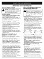
• IMPORTANT
SAFETY INFORMATION
READ ALL INSTRUCTIONS
1_,
BEFORE
SPECIAL SAFETY WARNINGS
FOR ELECTRIC
POWERHEADS
AND LAWN EDGERS
WARNING: To reduce the risk of electrical
shock, use only extension cords approved for
, outdoor use, such as an extension cord of cord
type SW-A, SOW-A, STW-A, STOW-A, SJW-A,
SJOW-A, SJTW-W or SJTOW-A. Extension
cords are available from your local retailer. Use
only round-jacketed extension cords approved
for outdoor use.
rules must be followed. For your own safety anc_
that of bystanders, please read these
|
WARNING:
instructions before
When using
operating
the unit,
the unit.
the safety
Please |/
keep the instructions safe for later use.
/
OPERATING
• Carefully read and understand the operator's manual
of the unit that powers this attachment.
• Read this operating instruction manual carefully. Be
thoroughly familiar with the controls and the proper use
of the equipment. Know how to stop the unit and
disengage the controls quickly.
• Do not operate this unit when tired, ill, or under the
influence of alcohol, drugs, or medication.
• Never allow children to operate the equipment. Never
allow adults unfamiliar with the instructions to use the
unit. Never allow adults to operate the equipment
without proper instruction.
• All guards and safety attachments must be installed
properly before operating the unit.
• Inspect the unit before use. Ensure the blade is
installed correctly and secure.
• Clear the area to be edged before each use. Remove
all objects such as rocks, broken glass, nails, wire, or
string which can be thrown or become entangled in the
edging attachment.
•
• CORD SETS: Make sure your cord set is in good
condition. When using a cord set, be sure to use a
cord that is heavy enough to carry the current that your
unit will draw. An undersized cord set will cause a drop
in line voltage resulting in loss of power and
overheating. See the operator's manual for the unit that
will power this add-on for the recommended cord size.
• Inspect all extension cords and the unit power
connection periodically. Look closely for deterioration,
cuts or cracks in the insulation. Also inspect the
connections for damage. Replace the cords if any
defects or damage appear.
• Prevent disconnection of the lawn edger powerhead
from extension cord during operation by using a plugreceptacle retaining strap, connector, or by making a
knot as shown below:
Extension
Cord
Lawn Edgorr
Cord
Extension
Cord
Lawn Edger
Cord
SPECIAL SAFETY WARNINGS
FOR GAS
POWERHEADS
AND LAWN EDGERS
WARNING: Gasoline is highly flammable, and its vapors
can explode if ignited. Take the following precautions:
• Store fuel only in containers specifically designed and
approved for the storage of such materials.
• Always stop the engine and allow it to cool before
filling the fuel tank. Never remove the cap of the fuel
tank, or add fuel, when the engine is hot. Never
operate the unit without the fuel cap securely in place.
Loosen the fuel tank cap slowly to relieve any pressure
in the tank.
• Mix and add fuel in a clean, well-ventilated area
outdoors where there are no sparks or flames. Slowly
remove the fuel cap only after stopping engine. Do not
smoke while fueling or mixing fuel. Wipe up any spilled
fuel from the unit immediately.
• Avoid creating a source of ignition for spilled fuel. Do
not start the engine until fuel vapors dissipate.
• Move the unit at least 30 feet (9.1 m) from the fueling
source and site before starting the engine. Do not
smoke. Keep sparks and open flames away from the
area while adding fuel or operating the unit.
• Never start or run the unit inside a closed room or
building. Breathing exhaust fumes can kill. Operate this
unit only in a well ventilated area outdoors.
• Avoid dangerous environments. Never operate your unit
in damp or wet conditions. Moisture is a shock hazard.
• Do not use the unit in the rain. Do not use in or around
water.
• Do not handle the plug or unit with wet hands or
standing on any wet surfaces.
• Do not leave the unit plugged in when not in use, changing
attachments or add-ons, or while being serviced.
WHILE OPERATING
• Keep bystanders, especially children and pets, at least
50 ft (15 m) away.
• Wear safety glasses or goggles that are marked as
meeting ANSI Z87.1 standards, and ear/hearing
protection when operating this unit. Wear a face or
dust mask if the operation is dusty.
• Wear heavy, long pants, boots, gloves and a long
sleeve shirt. Do not wear loose clothing, jewelry, short
pants, sandals or go barefoot. Secure hair above
shoulder level.
• Use the unit only in daylight or good artificial light.
• Use the right tool. Only use this tool for the purpose
intended.
3
•
Do not force unit. It will do the job better and with less
likelihood of injury at a rate for which it was designed.
• Use extreme caution when reversing or pulling the unit
towards you.
• Do not overreach, take extra care when working on
steep slopes or inclines. Always keep proper footing
and balance.
• Always hold the unit with both hands when operating.
Keep a firm grip on both the front and rear handle or
grips.
• Keep hands, face, and feet at a distance from all
moving parts. Do not touch or try to stop the blade
when it is rotating. Do not operate without guards in
place.
A coasting blade can cause injury while it continues to
spin after the unit is stopped. Maintain proper control
of the unit until the blade has completely stopped
rotating.
Use only genuine MTD replacement parts and
accessories for this unit. These are available from
your authorized service dealer. Use of any non-MTD
parts or accessories could lead to serious injury to the
user or damage to the unit, and void your warranty.
MAINTENANCE
AND STORAGE
• Allow the unit to cool before storing or transporting.
sure to secure the unit while transporting.
Be
• Store the unit in a locked up and dry or high and dry
place to prevent unauthorized use or damage, out of
the reach of children.
• Do not operate the engine faster than the speed
needed to do the job. Do not run the engine at high
speed when not in use.
• Clean the blade with a hose and water. Wipe the blade
with a light machine oil to prevent rust.
• Always stop the engine/motor when operation is
delayed or when walking from one location to another.
• Never douse or squirt the unit with water or any other
liquid. Keep handles dry, clean and free from debris.
Clean after each use.
• Stop the engine/motor for maintenance, repair, to
install or remove the blade. The unit must be stopped
and the blade no longer turning to avoid injury.
• The blade may become very sharp from use. Always
wear heavy gloves when handling, removing, installing
or cleaning the blade.
• If you strike or become entangled with a foreign object,
stop the engine/motor immediately and check for
damage. Have any damage repaired before attempting
further operations. Do not operate unit with a bent,
cracked or dull blade. Discard blades that are bent,
warped, cracked or broken.
• Stop the unit IMMEDIATELY if you feel excessive
vibration. Vibration is a sign of trouble. Inspect
thoroughly for loose nuts, bolts or damage before
continuing. Repair or replace affected parts as
necessary.
• Stop and switch the unit to off for maintenance, repair,
or for changing add-ons or other attachments.
• Keep unit clean of vegetation and other materials. They
may become lodged between the blade and gearbox
or guard.
4
Keep these instructions. Refer to them often and use
them to instruct other users. If you loan someone this
unit, also loan them these instructions.
Only qualified personnel should perform any repairs
or maintenance procedures that are not described
in this manual.
Check shear bolts, engine mounting bolts and other
bolts at frequent intervals for proper tightness to be
sure the equipment is in safe working condition.
Inside a building store the machine away from ignition
sources. Allow the engine to cool before storing in any
enclosure.
Always refer to the Operator's Manual instructions for
important details if the cultivator is to be stored for an
extended period.
Do not attempt to repair the machine unless you have
the proper tools, and instructions for disassembly and
repair of the machine.
SAVE THESE INSTRUCTIONS
L
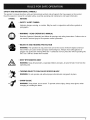
SAFETY
AND INTERNATIONAL
SYMBOLS
This operator's manual describes safety and international symbols and pictographs that may appear on this product.
Read the operator's manual for complete safety, assembly, operating and maintenance and repair information.
SYMBOL
MEANING
• SAFETY
ALERT
SYMBOL
Indicates danger, warning, or caution.
pictographs.
©
• WARNING
- READ OPERATOR'S
May be used in conjunction
with other symbols
MANUAL
Read the Operator's Manual(s) and follow all warnings and safety instructions.
can result in serious injury to the operator and/or bystanders.
WEAR
EYE AND HEARING
or
Failure to do so
PROTECTION
WARNING: The operation of any power tool can be the source of thrown objects and loud
noise which can cause severe eye injury and hearing loss. Always wear safety glasses or
goggles eye protection meeting ANSI Z87.1 standards and ear protection when operating this
unit. Use a full face shield when needed.
• KEEP BYSTANDERS
AWAY
WARNING: Keep all bystanders,
operating area.
• THROWN
OBJECTS
WARNING:
• SHARP
especially
CAN CAUSE
children and pets, at least 50 feet (15 m) from the
SEVERE
Do not operate unit without
INJURY
proper attachments
and guards in place.
BLADE
WARNING:
Sharp blade,do nottouch.To preventseriousinjury,
always wear gloves when
changing or handling the blade.
5
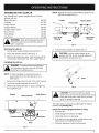
APPLICATIONS
With Edger Add-On:
• Edging along paths, driveways, rockedes, etc,
er
sha,,.ou
Blade
Shield
Depth
Adjustment
Kn_
__
__
/
Gearbox
Edger Blade
6
Blade Shield
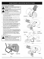
ASSEMBLING
THE COUPLER
The TrimmerPlus® system enables the use of these
optional add-ons.
Blower/Vacuum
..........................
BV720r
Cultivator
...............................
Hedge Trimmer
Sweeper/Blower
NOTE: Aligning the release button with the guide recess
will help installation (Fig. 1).
Coupler
..........................
..........................
Release Button
'\
GC720r
\
Primary
\\
HS720r
SB720r
Straight Shaft Trimmer .....................
Snow Thrower ...........................
SS725r
ST720r
Turbo Blower
TB720r
............................
Tree Pruner ..............................
TP720r
Hole
\
I
Lower Shaft
Housing
Upper Shaft
Housing
Knob /
manual for unit to be used with this add-on
ARNING:
Read and understand operator's
prior
to operation.
[,_
Removing the add-on:
1. Turn the knob counterclockwise to loosen (Fig. 1).
2.
Fig. 2
3.
CAUTION: Lock the release button in the
primary hole (Fig. 2) and securely tighten the
knob before operating this unit.
Press and hold the release button (Fig. 1).
3. While firmly holding the upper shaft housing, pull the
snow thrower attachment out of the coupler (Fig. 2).
Installing
I,_
Turn the knob clockwise to tighten (Fig. 3).
]
the add-on:
and damage to the unit, shut unit off before
WARNING:
avoid serious
removing or To
installing
add-ons.personal injury
/"
zz
NOTE: To make installing or removing the add-on
easier, place the unit on the ground or on a
work bench.
0
_Knob
I. Remove the hanger from the top of the shaft housing.
2. Turn knob counterclockwise to loosen (Fig. I).
3. While firmly holding the add-on, push it straight into
the coupler (Fig. 2).
Fig. 3
]
Coupler
'
x\\\\
Guide Recess
Release Button
[,_
\\
\
\\\
system are to be used in the primary hole only, I
Using
the wrong
hole could
personal //
CAUTION:
The add-ons
withlead
the to
coupler
injury or damage to the unit.
\
J
The edger add-on should be installed with the release
button in the primary hole.
Check Flex Shaft Engagement Prior to Using
1. Start the unit.
Counterclockwise
Knob
2.
Briefly engage and release the trigger.
3.
Check that add-on is operating.
4.
If the add-on is not operating, remove add-on and
repeat steps for installing the add-on.
5.
Recheck operation of add-on attachment.
Fig. 1
7
HOLDING
_
THE UNIT WITH
EDGER ADD-ON
body
protection
to reduce
the hearing,
risk of injury
ARNING:
Always
wear eye,
foot and
when operating this unit.
ADJUSTING
and proper
• The right arm is slightly bent, and the hand is holding
the shaft grip.
• The left arm is straight, and the hand is holding the
handle.
DEPTH
1.
Loosen the adjustment knob above the wheel
(Fig 6).
2.
Slide the wheel to the desired position.
• Raising the wheel increases the cutting depth.
3.
Tighten the adjustment knob securely.
Before operating the unit, stand in the operating position
(Figs. 4 & 5). Check for the following:
• The operator is wearing eye protection
clothing.
EDGER CUTTING
• Lowering the wheel decreases the cutting depth.
Depth Adjustment
/
Knob
• The unit is at waist level.
• The edger wheel adjusted for proper cut depth and
edger positioned as shown in Figs. 4 or 5.
Raising
t
Lowering
Fig. 6
TIPS FOR BEST EDGING
RESULTS
• Keep the cutting attachment perpendicular
ground.
to the
• Do not force the edger. Edge the first time at a lesser
depth,(No more than 1/2" depth cut per pass), then do
the area again with a deeper setting.
• Walk the edger at a slow, even pace
Fig. 4
Fig. 5
8
• Check the blade condition, as it wears it becomes
smaller, reducing the cutting depth performance.
Replace with a new blade as required.
EDGERBLADE REPLACEMENT
[,_
ARNING:
avoidwhi
serious
personal
injury, or
always
installing
wear
the To
gblade.
oves
e hand
ing, removing
I_lb
after long periods of use. To avoid serious
ARNING: The gear housing gets hot
hasPers°nacooled.njury'
do not touch the hous ng unt
1.
Line up the hole in output shaft with the locking rod
slot. Insert the locking rod through the slot into the
output shaft hole (Fig. 7).
2.
Hold the locking rod in place by grasping it next to
the boom of the unit (Fig.8).
t
I
Locking Rod
3. While holding the locking rod, loosen the nut on the
blade by turning it clockwise with a 5/8 inch wrench
(Fig. 9). Remove the nut, retaining washer and blade.
Keep the nut and blade retainer for installation.
4. Install the new blade, blade retainer, and nut
(Fig. 10). Insert the locking rod through the slot into
the output shaft hole. Make sure that the blade stays
flat and centered against the output shaft while
tightening the lock nut counterclockwise
(Fig. 11).
5.
If you have a torque wrench, tighten the nut to
325-335 in..Ibs (37-38 N.m), while holding the
locking rod in the slot.
If you do not have a torque wrench, hold the locking
rod in the slot. Rotate the nut counterclockwise
with
a 5/8 inch closed-ended or socket wrench, until the
nut presses against the washer and the blade is
snug. Make sure the blade assembly is installed
correctly, then rotate the nut an additional 1/4-1/2
turn (Fig. 11).
6.
I_ID
Loosen
Fig. 9
Edger Blade_
_
_de
Lock Nut
Retainer
Remove the locking rod.
output shaft after the nut is tightened. If the
blade is off-center, the unit will be
damaged
vibration,
and the
blade
may the
fly
ARNING:byVerify
the blade
is flat
against
off, which can cause serious personal injury.
Locking Rod
Fig. 10
Locking Rod
Locking Rod
Slot
Fig. 7
Tighten
Output Shaft
Fig. 11
9
STORAGE
ACCESSORIES/REPLACEMENT
• Check unit before storage to be sure the equipment is
in safe working condition.
• Stop the engine or motor.
Blade ..............................
Blade Retainer ........................
Lock Nut .............................
• Store the unit indoors, in a dry and locked place, out of
the reach of children.
Use only original MTD replacement
• Maintain or replace safety and instruction labels, as
necessary.
For gas powerhead
units:
• Allow the unit to cool before storing in any enclosure.
• Drain fuel from unit. Never store the unit with fuel in the
fuel tank inside a building where ignition sources are
present such as hot water and space heaters, clothes
dryers, etc.
TRANSPORTING
• Allow the unit to cool before transporting.
• Secure the unit while transporting.
For gas powerhead
units:
• Drain fuel from unit.
• Tighten fuel cap before transporting.
10
PARTS
791-613223B
791-147490
791-147491
parts.
Unit Weight (Add-On only) .........................................................
Cutting Depth (maximum) ...........................................................
Wheel Diameter .................................................................
Gearbox Ratio ............................................................................
5.25 Ibs. (2.36 kg.)
2.5 in, (63.5 mm)
3.75 in (95,25 mm)
1,23:1
11
MANUFACTURER'S
LIMITED WARRANTY FOR:
Trimmer :
The limited warranty set forth below is given by MTD
SOUTHWEST INC ("MTD") with respect with new
merchandise purchased and used in the United States, its
possessions and territories.
MTD warrants this product against defects in material and
workmanship for a period of two (2) years commencing on the
date of original purchase and will, at its option, repair or
replace, free of charge, any part found to be defective in
material or workmanship. This limited warranty shall only apply
if this product has been operated and maintained in
accordance with the Operator's Manual furnished with the
product, and has not been subject to misuse, abuse,
commercial use, neglect, accident, improper maintenance,
alteration, vandalism, theft, fire, water, or damage because of
other peril or natural disaster. Damage resulting from the
installation or use of any accessory or attachment not
approved by MTD for use with the product(s) covered by this
manual will void your warranty as to any resulting damage.
This warranty is limited to ninety (90) days from the date of
original retail purchase for any MTD product that is used for
rental or commercial purposes, or any other incomeproducing purpose.
°
No implied warranty, including any implied warranty of
merchantability
or fitness for a particular purpose,
applies after the applicable period of express written
warranty above as to the parts as identified. No other
express warranty or guaranty, whether written or oral,
except as mentioned above, given by any person or
entity, including a dealer or retailer, with respect to any
product shall bind MTD. During the period of the
Warranty, the exclusive remedy is repair or replacement
of the product as set forth above. (Some states do not
allow limitations on how long an implied warranty lasts, so
the above limitation may not apply to you.)
The provisions as set forth in this Warranty provide the
sole and exclusive remedy arising from the sales. MTD
shall not be liable for incidental or consequential loss or
damages including, without limitation,
expenses
incurred for substitute or replacement
lawn care
services, for transportation or for related expenses, or
for rental expenses to temporarily replace a warranted
product. (Some states do not allow limitations on how long
an implied warranty lasts, so the above limitation may not
apply to you.)
HOW TO OBTAIN SERVICE: Warranty service is available,
WITH PROOF OF PURCHASE THROUGH YOUR LOCAL
AUTHORIZED SERVICE DEALER. To locate the dealer in your
area, please check for a listing in the Yellow Pages or contact
the Customer Service Department of MTD SOUTHWEST INC
by calling 1-800-345-8746 or writing to 550 N 54th Street,
Chandler, Arizona 85226 or if in Canada call 1-800-668-1238.
No product returned directly to the factory will be accepted
unless prior written permission has been extended by the
Customer Service Department of MTD SOUTHWEST INC.
In no event shall recovery of any kind be greater than the
amount of the purchase price of the product sold. Alteration
of the safety features of the product shall void this Warranty.
You assume the risk and liability for loss, damage, or injury
to
you
and
your
property
and/or
to
others and their property arising out of the use or misuse or
inability to use the product.
This limited warranty does not provide coverage in the
following cases:
How State Law Relates to this Warranty: This warranty
gives you specific legal rights, and you may also have other
rights which vary from state to state.
A. Wear items - Bump Knobs, Outer Spools, Cutting Line,
Inner Reels, Starter Pulley, Starter Ropes, Drive Belts
B.
MTD does not extend any warranty for products sold or
exported outside of the United States of America, its
possessions
and territories, except those sold through
MTD's
authorized
channels
of export
distribution
MTD reserves the right to change or improve the design of
any TrimmerPlus® Product without assuming any obligation
to modify
any product
previously
manufactured.
This limited warranty shall not extend to anyone other than
the original purchaser, original lessee or the person for
whom it was purchased as a gift.
To locate your nearest service dealer dial
1-800-345-8746 in the United States or
1-800-668-I 238 in Canada.
MTD SOUTHWEST
INC
550 N. 54th Street
Chandler, AZ 85226 U.S.A.
SAVE THESE INSTRUCTIONS
FOR FUTURE
FOR QUESTIONS CALL 1-800-345-8746
OR 1-800-668-1238
IN CANADA
OPERATOR'S MANUAL PART NO. 770-10668
PRINTED IN U.S.A.
REFERENCE.
IN U.S.
REV. P00
11/01