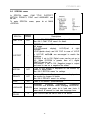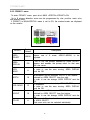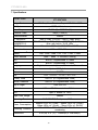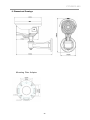
1
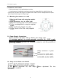
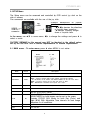
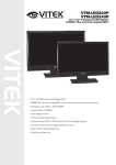
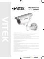
VTC-IRH70/650
Long Range Weatherproof IR
Bullet Camera
VITEK
• 1/3” Super HAD Color CCD
• High Resolution with 560 TV Lines Resolution in Color (600 TV Lines in B/W mode)
• 70 IR LEDs at 850nm enable viewing in Total Darkness up to 300 Feet
• Simultaneous Color and Black & White Focus Adjustment
• Infrared LED Dynamic Intensity Control with automatic brightness adjustment of IR LEDs
to help prevent washed out images when objects are too close
• Camera and IR LED compartments are separated using a dual glass design to prevent
stray IR light from entering the lens
• Vari-Focal 6~50mm DC Auto Iris IR Lens
• Virtual Wide Dynamic Range
• OSD control
• Secondary Video Output & OSD Control Joystick are accessible inside a gasket sealed
removable side panel
• Externally adjustable Focus & Zoom with clutch mechanism to eliminate over-tightening
• Gasket sealed external focus and zoom controls with clutch mechanism to eliminate
over-tightening for ease of installation and adjustment
• Heavy Duty IP68 rated Weather/Vandal Resistant Aluminum Construction is 100% water
and dust proof
• Fully adjustable 3 axis wire feed-through mount
• Dual Voltage: 12VDC / 24VAC
cyan
magenta
yellow
black
VTC-IRH70-650 Table of contents
1. Safety Instructions and Notes.................................................................................. 2
2. General Descriptions ............................................................................................... 3
3. Supplied Items ......................................................................................................... 3
4. Part names .............................................................................................................. 4
5. Installation Instructions ............................................................................................ 5
5.1.
Mounting The Camera ......................................................................... 5
5.2.
Power Supply Connections.................................................................. 5
5.3.
Setup of Zoom and Focus ................................................................... 5
6. Setup Menu ............................................................................................................. 6
6.1
Main Menu........................................................................................... 6
6.2
6.2.1
Exposure Menu ................................................................................... 7
BLC Menu ........................................................................................... 8
6.2.2
HSBLC Menu ...................................................................................... 9
6.2.3
D-WDR Menu ..................................................................................... 10
6.3
Day Night Menu.................................................................................. 10
6.3.1
Day Night Auto Menu ......................................................................... 10
6.4
3-DNR Menu ...................................................................................... 12
6.5
Picture Menu ...................................................................................... 13
6.6
Special Menu...................................................................................... 14
6.6.1
Camera Title Menu ............................................................................. 15
6.6.2
Motion Menu....................................................................................... 16
6.6.3
Privacy Menu...................................................................................... 17
6.7.
Lens Menu.......................................................................................... 18
6.7.1
Focus Adjust Menu............................................................................. 18
7. Specifications.......................................................................................................... 19
8. Dimensional Drawings ............................................................................................ 20
9. Warranty ................................................................................................................. 21
1
VTC-IRH70-650 WARNING
The symbol is intended to alert the user to the presence of important
operating and maintenance(servicing) instructions in the literature
accompanying the unit.
The symbol is intended to alert the user to the presence of
un-insulated "dangerous voltage" within the product's enclosure that
may be of sufficient magnitude to constitute a risk of electric shock.
Caution
To prevent electric shock
and risk of fire hazards, do
NOT
use
other
than
specified power source.
Warning(NTSC version) -- This equipment has been tested and found to comply with the limits for a Class
A digital device, pursuant to part 15 of the FCC Rules. These limits are designed to provide reasonable
protection against harmful interference when the equipment is operated in a commercial environment. This
equipment generates, uses, and can radiate radio frequency energy and, if not installed and used in
accordance with the instruction manual, may cause harmful interference to radio communications.
Operation of this equipment in a residential area is likely to cause harmful interference in which case the
user will be required to correct the interference at his/her own expense.
Caution -- Any changes or modifications in construction of this device which are not expressly approved by
the party responsible for compliance could void the user's authority to operate the equipment.
1. Safety Instructions and Notes
• Please read these safety and operating instructions before placing the camera into
operation.
• Keep the manual in a safe place for later reference.
• Pay attention to safety when laying the connection cable and observe that the
cable is not subjected to
heavy loads, kinks, damage or moisture.
• Never open the device to expose boards or lens.
The warranty becomes void if repairs are undertaken by unauthorized persons.
• Maintenance and repair must be carried out only by authorized service centers.
• Use only a mild detergent to clean the housing.
• Keep the window surface clean from dirt or dust, which may reflect the infrared
light into the lens at night..
• The camera should never be operated in an environment that exceeds the technical specifications as this
may result in the destruction of the product and will also void the factory warranty.
2
VTC-IRH70-650 2. General Descriptions
Main Features
·
·
·
·
·
·
Fully external adjustment controls for lens, OSD or Dip switch settings
1/3" Super HAD II CCD
High Resolution 560TVL (Color), 600TVL (B/W)
3-DNR (3 Dimensional Digital Noise Reduction)
Extended Dynamic Range by the use of D-WDR technology
Sensitivity: COLOR: 0.35Lux (@50IRE, F1.2), B/W: 0.04Lux (@50IRE, F1.2),
SENSE-UP(x4): 0.0035Lux (@50IRE, F1.2), 0 Lux with built-in 70 Infrared LEDs on
· Cable feed-through wall bracket (Concealed Wiring Bracket)
· 6~50mm Variable Focal Length Lens
· Weatherproof (IP68) Optimized for Outdoor Use
. OSD (On Screen Display) Function Control
. Sense-up (~ x128)
. AWB, Flickerless, Digital Zoom, BLC and HSBLC
. Motion Detection (4 Zone), Privacy Zone (8 zones), Flip Function
· 24VAC / 12VDC Dual Power
· Secondary Video output for simple installation & maintenance
· Easy adjustment for zoom, focus and OSD controls
· 70x Self Adjusting IR LEDs
· 300' Night observation range
Contains Sony Super HAD II CCD image sensor,
· Provides a brighter image and true color reproduction while extending the
viewing range in low lux (light) conditions with double the sensitivity of other
sensors.
Extensive DAY-NIGHT capabilities,
- True (ICR) DAY-NIGHT Function
- No compromising image color under low color temperature (incandescent light).
- Features 70 Infrared LEDs affording clear images up to 300’ where no
illumination is available.
With 24VAC/12VDC dual power design,
- Offering flexibility during installation and reduces risk of damage due to voltage
3. Supplied Items
•
•
•
•
•
•
•
•
•
1x
1x
1x
1x
4x
1x
1x
1x
1x
VTC-IR70650 3-DNR Weatherproof IR Bullet Camera
ⓓ Sunshield with ⓐ attachment thumb screw
3mm Hex L-wrench
5mm Hex L-wrench
Wall mounting screws with anchors
Installation and Operating manual
Mounting template
Video Sub-output cable
Mounting plate adaptor for easy installation
3
VTC-IRH70-650 4. Part Names
4.1 Front view
ⓐ ⓓ ⓔ ⓑ ⓒ ⓖ ⓐ Sunshield attachment thumb screw
ⓑ IR LED Panel
ⓒ Double Glass Window
ⓓ Sunshield
ⓕ ⓔ On Screen Display control cover
ⓕ Wall Mounting Bracket
ⓖ Mounting Plate Adaptor
4.2 Rear side view
① ② ① Focus adjustment
② Zoom adjustment
4
VTC-IRH70-650 5. Installation Instructions
• Make sure the power is not applied before installation.
• Once the camera is installed you may first connect the low voltage (DC12V or AC24V) wire to the
camera power connector, then plug the AC adapter to AC outlets to avoid an improper reset from power
jitter and possible damage from voltage surge.
5.1. Mounting the camera on a wall
1) Make the drill holes with using the supplied
template.
2) Insert the anchors into the drilled holes
3) Match the mounting plate to the drilled position
4) Fix the mounting plate by using the supplied
screws
5) Slide the Mounting Bracket into place
6) Fix the Mount to the Plate using supplied
screws
5.2. Power Supply Connections
Camera can work with either 24AC or 12VDC, dual voltage power.
It is strongly required the polarity-matched connection for 12VDC supply,
otherwise IR LEDs will not operate at night.
Primary and secondary grounds are completely isolated to avoid the possibility of
ground-loop problems.
Clamp connectors of power
input
AC24V/DC12V (RED WIRE)
AC24V/GND (BLACK WIRE)
5.3. Setup of the Zoom and FOCUS
1) Power up the camera and connect a monitor.
2) Enter LENS>DC>FOCUS ADJUST in MENU
3) Set ②Zoom adjustment first, then adjust ①Focus adjustment. The lens
adjustment is completed.
4) Exit MENU.
5
VTC-IRH70-650 6. SETUP Menu
The Setup menu can be accessed and controlled by OSD control joy stick on the
side of camera.
Five commands are available with the use of the joy stick.
SYMBOL descriptions for joystick
operation;
-▲,▼,◀,▶ denotes the directions
VIDEO
of Joystick lever operation. SUB-OUT
-● denotes Pressing straight
connector down of Joystick lever In the menu, use ▲,▼ to move menu, ◀,▶ to change the settings and press ● to
select or enter.
Joy
stick FACTORY DEFAULT in this manual may NOT be identical to the default values
set by the FACTORY due to feature improvements or custom requirements.
6.1 MAIN menu - To enter menu, press ● when MENU is not active..
MAIN
EXPOSURE
DAY/NIGHT
3DNR
Factory
Default
-
AUTO
ON
Descriptions
Sets SHUTTER, AGC, SENSE-UP, BLC and D-WDR.
Sets DAY / NIGHT to AUTO, NIGHT and DAY.
AUTO – Camera switches DAY from/to NIGHT automatically. DELAY,
D-->N LEVEL, N-->D LEVEL and NIGHT MODE can be set in the menu.
NIGHT – Forced to remove IR cut filter and switch to B/W.
DAY – DAY/NIGHT is disabled and outputs color video..
Sets 3DNR (Digital Noise Reduction) LEVEL.
PICTURE
-
sets SHARPNESS, BLUE, RED, GAMMA and WHITE BALANCE.
SPECIAL
-
Sets CAM TITLE, D-EFFECT, MOTION, PRIVACY, SYNC, LANGUAGE and
OSD (On Screen Display) COLOR.
LENS
DC
Selects DC (Auto Iris) or MANUAL lens.
BRIGHTNESS for both lenses can be set in the menu.
Provides FOCUS ADJ. Mode for both Day (Color) and
Night (B/W) With Adjustable Time intervals for best image
sharpness in all conditions.
FACTORY SET
NO
Restores and saves FACTORY DEFAULTS.
EXIT
-
Save and Exit.
6
VTC-IRH70-650 6.2 EXPOSURE menu
To enter EXPOSURE menu, press ● at MAIN>EXPOSURE.
EXPOSURE
Factory
Default
Descriptions
1/60
(1/50)
1) If LENS at MAIN menu was set to DC, a fixed shutter is selectable
from 1/60(NTSC) or 1/50(PAL), FLK, 1/250, 1/500, 1/2000, 1/5000,
1/10000, 1/100000 and a fixed sense-up rate is selectable from
x256, x128, x64, x32, x16, x8, x4, x2.
At x2~x256, DSS(Digital Slow Shutter) is operating with the selected
frame integration rates regardless of the light level.
When TV system is NTSC(PAL) and Main power is 50Hz(60Hz),
set to FLK(Flickerless mode).
FLK makes the sensitivity lower about 30% at low light.
DC lens must be used for these settings to get a proper video
level.
AUTO
2) If LENS at MAIN menu was set to MANUAL, SHUTTER should be
set to AUTO to get a proper video level with the automatic shutter
range between 1/60(1/50)~1/100,000sec.
Color rolling or Video level hunting under Fluorescent or similar
lighting may occur in this configuration.
.
SHUTTER
--AGC
MIDDLE
SENSE-UP
OFF
or
AUTO
1) If DAY / NIGHT at MAIN menu was set to AUTO or NIGHT,
AGC is not user adjustable.
2) AGC can be set to MIDDLE, HIGH, OFF or LOW.
Settings are not available if DAY /NIGHT at MAIN menu is set to
AUTO
SENSE-UP is available only when SHUTTER is 1/60(1/50) or AUTO.
If set to AUTO, max. integration rate for DSS can be set to x2, x4, x8,
x16,
x32, x64, x128 or x256..
The integration frames vary automatically within the max. rate
according to
the light level when light becomes low and DSS is operating.
The higher sense-up rate, the higher sensitivity but the slower refresh
rate.
Some white dots may appear by sense-up due to CCD’s long
accumulation
caused by a long shutter period.
BLC
OFF
OFF, BLC and HSBLC are available.
See BLC & HSBLC menus at 6.2.1 & 6.2.2 for detail.
D-WDR
OFF
COMP. and HIGH SUP. can be set.
See D-WDR menu at 6.2.3 for details
7
VTC-IRH70-650 6.2.1 BLC menu
To enter BLC menu, press ● at EXPOSURE > BLC > BLC.
BLC
GAIN
DEFAULT
HOR.
MOVE
Factory
Default
Descriptions
LOW
Sets the compensation gain to LOW, MIDDLE or HIGH.
For best compensation results, adjust window for size
and location as well as GAIN.
Back Light Compensation (BLC) may not be precise if
the background is varying continuously between bright
and dark.
-
Loads the default for BLC settings.
2
◀ moves BLC window leftward and ▶ moves it rightward
WIDTH
4
VER. MOVE
4
HEIGHT
3
◀ decreases and ▶ increases WIDTH of BLC window
from the right.
◀ moves BLC window upward and ▶ moves it
downward.
◀ decreases and ▶ increases HEIGHT of BLC window
from the bottom.
BLC OFF BLC ON 8
VTC-IRH70-650 6.2.2 HSBLC menu - High Light Masking
To enter HSBLC (High Sensitivity BLC) menu, press ● button at EXPOSURE >
BLC > HSBLC.
HSBLC cuts out the highlighted video and processes that area as black masked.
The cut out video is excluded in measuring light level by the signal processor.
Factory
Default
Descriptions
LEVEL
8
Sets the threshold for highlight cut out between 0~8.
Lower setting is more sensitive and starts cutting out
from lower level
of highlight. The cut out area is masked by black color.
DEFAULT
-
Loads the default for HSBLC settings.
HOR.
MOVE
1
◀ moves BLC window leftward and ▶ moves it rightward.
WIDTH
6
◀ decreases and ▶ increases WIDTH of BLC window
from the right.
VER. MOVE
2
◀ moves BLC window upward and ▶ moves it downward.
HEIGHT
4
◀ decreases and ▶ increases HEIGHT of BLC from the
bottom.
BLC
HSBLC OFF HSBLC ON 9
VTC-IRH70-650 6.2.3 D-WDR menu
To enter D-WDR (Digital Wide Dynamic
Range) menu, press ● at EXPOSURE > DWDR > ON.
D-WDR improves the dynamic range of
video by means of digital compensation for
the dark and highlighted areas.
Factory
Default
Descriptions
LOW
COMP.
10
LOW COMP. is a compensation gain for the dark area
level. Higher value gets higher compensation.
Noise will also be increased by this compensation.
HIGH SUP.
95
HIGH SUP. is a suppression gain for the highlighted
area level. Higher value gets higher suppression.
D-WDR
DEFAULT
-
Loads the default for D-WDR.
6.3 DAY / NIGHT menu
6.3.1 DAY / NIGHT AUTO menu
To enter DAY/NIGHT AUTO menu, press ● at MAIN > DAY/NIGHT > AUTO.
Threshold levels for D-->N and N-->D can be set.
When switched to NIGHT, camera removes its IR cut filter and switches to B/W
mode.
Non-IR LED version IR LED version IMPORTANT!!! DAY->NIGHT and NIGHT->DAY operations must be examined and verified at the final step of the installation. Block the
lens for a few seconds for NIGHT mode and release and let it return to
DAY mode. If camera stays at NIGHT mode more than 10sec, decrease N->D LEVEL a little and repeat the fore- mentioned steps. If the scene is too
dim or lens iris was adjusted near close, it may not return to DAY.
10
VTC-IRH70-650 DAY NIGHT
AUTO
Factory
Default
DELAY
5
D-->N
LEVEL
35
N-->D
LEVEL
85
NIGHT
MODE
B/W
Descriptions
DELAY is the duration which should maintain its status
before making
the D-->N or N-->D switches. Camera checks the light
level
seamlessly to determine if it crosses over the
threshold levels of D-->N LEVEL or N-->D LEVEL. The
state must maintain unchanged for longer than DELAY
time in order to force switchover.
DELAY is used to avoid the unwanted switching by
short term lights such like the light from the passing
car.
D-->N LEVEL is a threshold level to switch from DAY
to NIGHT.
Higher value makes camera enter NIGHT mode at a
brighter light level.
To enter NIGHT mode at a lower illumination,
decrease the value.
Try NOT to make the gap too small between D->N LEVEL and N-->D
LEVEL to avoid continual switching.
N-->D LEVEL is a threshold level to switch from
NIGHT to DAY.
Higher value makes camera exited NIGHT at brighter
light level.
TO
EXIT
NIGHT
MODE
AT
BRIGHTER
ILLUMINATION,
INCREASE it and vice versa
Try NOT to make the gap too small between D->N LEVEL and N-->D
LEVEL to avoid the switch repeating.
If set to B/W, camera will output B/W video at NIGHT.
In B/W mode, BURST can be set to OFF(default) or
ON in DAY/NIGHT B/W menu. BURST OFF shows
sharper and better resolution however some equipment
may function inconsistently with BURST OFF.
If set to COLOR, video will remain in color at NIGHT
when DAY/NIGHT in main menu is set to AUTO.
The ICR (Infrared Cut Removal) function will be
disabled however this may result in poor or inaccurate
color due to the presence of the IR light spectrum.
The settings for BURST will also affect any NIGHT
mode.
11
VTC-IRH70-650 CAUTION b
1) DAY / NIGHT AUTO menu is strongly recommended to be adjusted for
the actual object after completing all settings of the lens.
2) If the gap between D-->N LEVEL and N-->D-LEVEL becomes too small,
it is easy to repeat switching from/to DAY/ NIGHT continuously.
The recommended Gap is greater than 45.
If the switching between DAY and NIGHT repeats, decrease D-->N and
increase N-->D
slightly in turn until the repeating stops.
6.4 3DNR menu
3DNR is a very sophisticated and powerful noise reduction technology.
The camera evaluates the real image and the noise within the horizontal and vertical
blocks frame by frame and reduces the noise over three dimensions.
To enter 3DNR menu, press ● at MAIN > 3DNR > ON.
Higher settings in LEVEL will result as increased noise reduction.
When 3DNR is ON in MAIN menu, a short motion blur or comet effect may be seen
on fast moving targets in low light.
12
VTC-IRH70-650 6.5
PICTURE menu
In PICTURE menu, SHARPNESS, BLUE, RED, GAMMA and WHITE BAL. can be
set.
To enter PICTURE menu, press ● at MAIN >PICTURE
PICTURE
Factory
Default
SHARPNESS
13
BLUE
90
RED
70
GAMMA
0.45
WHITE BAL
ATW
Descriptions
Increases or decreases the sharpness of the picture.
Too much sharpness makes the image harsh and
shows increased noise and line flicker at the edges of
objects in the picture.
Increases or decreases the blue color gain of the
picture
Increases or decreases the red color gain of the
picture
Adjustable by 0.05.
Lower value increases the gain of the dark area and
vice versa.
13
6.6
VTC-IRH70-650 SPECIAL menu
In SPECIAL menu, CAM TITLE, D-EFFECT,
MOTION, PRIVACY, SYNC and LANGUAGE. can
be set.
To enter SPECIAL menu, press ● at MAIN
>SPECIAL
SPECIAL
Factory
Default
CAM TITLE
OFF
D-EFFECT
-
MOTION
OFF
PRIVACY
OFF
SYNC
INT
LANGUAGE
OSD
COLOR
Descriptions
If set to ON, CAM TITLE is displayed on the screen.
See ‘6.6.1 CAM TITLE menu’ for detail.
FREEZE: If set to ON, image freezes and shows a
still image.
FLIP:OFF(normal
display),
H-FLIP(Left
&
right
mirrored),
V-FLIP(upside down) and H/V FLIP. In case of V-FLIP
or H/V-FLIP, ▲,▼,◀,▶ are rearranged to match the
directions.
D-ZOOM: If set to ON, Digital zoom can be set up to
x32. When D-ZOOM is greater than x1.1, digital
PAN/TILT can be set.
NEG.IMAGE: If set to ON, Negative image is output
and used to see as a negative film effect.
If set to ON, motion is displayed on the monitor by
means of digital effect.
See ‘6.6.2 MOTION menu’ for settings.
If set to ON, up to 8 privacy masks are displayed on
the monitor by means of blocks.
See ‘6.6.3 PRIVACY menu’ for settings.
Fixed to INTERNAL synchronization.
ENGLISH,
KOREAN,
JAPANESE,
CHINESE1,
CHINESE2 are available. When changing LANGUAGE,
ENGLISH select language and press ● to load new fonts. It
takes about 8 seconds to load new language fonts.
3
OSD COLOR can be set to one of 16 colors.
14
VTC-IRH70-650 6.6.1 CAM TITLE menu
To enter CAM TITLE menu, press ● at MAIN >SPECIAL>CAM TITLE>ON
Command line CAM TITLE input line Up to 15 characters from the character table can be input.
Use ▲,▼,◀,▶ to move cursor (Blinking character is on the cursor position) in the
character table.
Press ● to select and the selected character will be input and displayed on CAM
TITLE input line.
To move the input position CAM TITLE input line, press ● on
To clear CAM TITLE input line, press ● on CLR on command line.
To set the location of CAM TITLE to be displayed on the video, press ● on POS on
command line
The menu will disappear and CAM TITLE will be displayed on the video.
Use ▲,▼,◀,▶ to locate CAM TITLE in the proper position and press ● to fix.
The Menu will appear again.
To finish/close CAM TITLE menu, press ● on RET on command line. 15
VTC-IRH70-650 6.6.2 MOTION menu
To enter MOTION menu, press ● at MAIN
>SPECIAL>MOTION>ON.
Up to 4 motion detection areas can be
programmed by size, position, sensitivity and
display on/off.
If MOTION in MAIN>SPECIAL menu is set to
ON, ‘MOTION’ is displayed on the monitor
whenever the motion is detected and the
digital effect will appear if MOTION VIEW is
set to ON.
MOTION
Factory
Default
AREA
SELECT
AREA1
AREA
DISPLAY
ON
HOR. MOVE
12
WIDTH
32
VER. MOVE
7
HEIGHT
24
SENSITIVITY
40
MOTION VIEW
OFF
Descriptions
Selects one of 4 areas, AREA1~AREA4, to be
adjusted.
If set to ON, the window selected by AREA SELECT
appears and enables the motion detection for that
area and vice versa.
Moves the window selected by AREA SELECT
leftward or rightward. In order to see the area
moving, AREA DISPLAY must be ON.
◀ decreases and ▶ increases WIDTH of the window
selected by AREA SELECT from the right.
In order to see the change, AREA DISPLAY must be
ON.
Moves the window selected by AREA SELECT
upward or downward. In order to see the area
moving, AREA DISPLAY must be ON.
◀ decreases and ▶ increases HEIGHT of window
selected by AREA SELECT from the bottom. In order
to see the change, AREA DISPLAY must be ON.
Motion SENSITIVITY may be adjusted between 0 and
40 for the window selected by AREA SELECT.
If set to OFF, motion result will not be displayed.
16
VTC-IRH70-650 6.6.3 PRIVACY menu
To enter PRIVACY menu, press ● at MAIN >SPECIAL>PRIVACY>ON.
Up to 8 privacy detection areas can be programmed by size, position, mask color
and display on/off.
If PRIVACY in MAIN>SPECIAL menu is set to ON, the masked areas are displayed
on the monitor.
PRIVACY
Factory
Default
Descriptions
AREA
SELECT
AREA1
AREA
DISPLAY
ON
If set to ON, the window selected by AREA SELECT
appears and enables the privacy mask for that area
and vice versa. 8
In order to see the area moving, AREA DISPLAY
must be ON. HOR.
MOVE
WIDTH
16
VER. MOVE
12
HEIGHT
16
COLOR
0
Selects one
adjusted. of
8
areas,
AREA1~AREA8,
to
be
◀ decreases and ▶ increases WIDTH of the window
selected by AREA SELECT from the right.
In order to see the change, AREA DISPLAY must be
ON.
Moves the window selected by AREA SELECT upward
or downward.
In order to see the area moving, AREA DISPLAY
must be ON.
◀ decreases and ▶ increases HEIGHT of window
selected by AREA SELECT from the bottom.
In order to see the change, AREA DISPLAY must be
ON.
Sets one of 16 colors for the mask window selected
by AREA SELECT.
Each area color can be selected individually.
17
VTC-IRH70-650 6.7 LENS menu
Lens can be selected as either DC (Auto Iris) or MANUAL (Disabled A/I function).
To enter DC/MANUAL LENS menu, press ● button at MAIN >LENS>DC(MANUAL).
BRIGHTNESS can be adjusted. It takes about 5 seconds for brightness to settle
after the adjustment.
CAUTION b
Be careful NOT to overly decrease the BRIGHTNESS. If the DC iris is set too
low, it may cause difficulty for the camera when it returns from NIGHT to DAY due
to diminished or incidental light .
6.7.1 FOCUS ADJ. menu
Sometimes the focus - when adjusted in very bright daylight - becomes blurry at
night. This condition is commonly referred to as "Focus Shift". The FOCUS ADJ.
menu is used to assist with easy adjustments to sharpen the image with the use of
ZOOM and FOCUS eliminating this kind of error by simulating the conditions of
night time. D/N DWELL is used to adjust the period between switching from Color
(day) to ICR (night).
Set the ZOOM first and then adjust the FOCUS precisely in order to achieve a
sharp image while
switching between day and night modes.
18
VTC-IRH70-650 7. Specifications
Model Name
VTC-IRH70650
Image Device
1/3" Sony New Structure Super HAD Color CCD
TV System
NTSC, 2:1interlace
Scan Freq.
59.94Hz(V), 15.734Khz(H)
Effective Pixels
768(H) x 494(V)
Synchronization
Internal
H. Resolution
Sensitivity
(@50IRE,F1.2)
S/N Ratio
560TV Lines (COLOR) / 600TV Lines (B/W)
COLOR: 0.35Lux, B/W: 0.04Lux, SENSE-UP(x4):0.0035Lux
0Lux with built-in 70 IR LEDs
More than 50dB with AGC OFF at 50IRE
Electronic Iris
Manual
Shutter
Speed
White Balance
1/60 ~ 1/100,000sec
1/60, 1/250, 1/500, 1/2K, 1/5K, 1/10K, 1/100K
2000 ~ 8000°K Automatic tracking
BLC
Built-in, Programmable in menu
AGC
Built-in, Programmable in menu
Language
English, Korean , Japanese, Chinese I, Chinese II
Zoom
Up to x32 Digital zoom
Flickerless
Flip
ON/OFF
OFF / H-FLIP / V-FLIP / H/V FLIP
Privacy Zone
ON/OFF (8 Programmable Zone)
Motion Detection
ON/OFF (4 Programmable Zone)
Day & Night
True D/N ICR
Built-in Lens
6-50mm DC Drive auto Iris, D/N lens
LED
70pcs x 850nm IR LEDs
Night View Range
Operating Power
Power Consumption
Operating Condition
Dimensions
300feet
24VAC/12VDC Dual power, 12W max.
800ma LEDs on (12vdc) - 500ma LEDs on (24VAC)
120ma LEDs off (12vdc) - 70ma LEDs off (24VAC)
-4ºF~+122ºF / -20ºC~+50ºC, 85% RH. Max. noncondensing
4.52"(W) x 9" (L) / 115mm(W) x 228.5mm(L)
19
VTC-IRH70-650 8. Dimensional Drawings Mounting Plate Adapter 20
VTC-IRH70-650 9. Warranty
VITEK LIMITED PRODUCT WARRANTY
VITEK products carry a three (3) year limited warranty. Digital recording and storage products are
also warranted for 3 years except for the hard drives which carry their own independent factory
warranty from the hard drive manufacturer. VITEK warrants to the purchaser that products
manufactured by VITEK are free of any rightful claim of infringement or the like, and when used
in the manner intended, will be free of defects in materials and workmanship for a period of
three (3) years, or as otherwise stated above, from the date of purchase by the end user. This
warranty is non-transferable and extends only to the original buyer or end user customer of a
Vitek Authorized Reseller.
The product must have been used only for its intended purpose, and not been subjected to
damage by misuse, willful or accidental damage, caused by excessive voltage or lightning.
The product must not have been tampered with in any way then the guarantee will be
considered null and void.
This guarantee does not affect your statutory rights.
Contact your local VITEK Reseller should servicing become necessary.
Vitek makes no warranty or guarantee whatsoever with respect to products sold or purchased
through unauthorized sales channels. Warranty support is available only if product is purchased
through a Vitek Authorized Reseller.
21
ALSO AVAILABLE FROM VITEK:
22
VTC-IRH70-650 28492 Constellation Road Valencia, ca 91355
WWW.VITEKCCTV.COM | 888-VITEK-70