1
®
Caution:
ReadandFollow
AllSafetyRules
andInstructions
BeforeOperating
ThisEquipment
5.0 HORSEPOWER
21" POWER PROPELLED
5=SPEED "3=lN=l"
MULCHING ROTARY MOWER
Assembly
Operation
Maintenance
Service and Adjustment
Repair Parts
SEARS,ROEBUCK
ANDCO.,HoffmanEstates,IL 60179 U.S.A.
THISSYMBOLPOINTSOUTIMPORTANT
SAFETYINSTRUCTIONS
WHICH,IF NOTFOLLOWED,
COULDENDANGER
THEPERSONAL
SAFETYAND/ORPROPERTY
OFYOURSELF
AND OTHERSREADAND FOLLOWALL INSTRUCTIONS
IN THIS MANUALBEFORE_
ATTEMPTING
TOOPERATE
YOURLAWNMOWER.FAILURETOCOMPLYWITHTHESEINSTRUCTIONS
MAYRESULTIN PERSONAL
INJURYWHENYOUSEETHISSYMBOL--_
HEEDITSWARNING.
&
DANGER: with anytypeof powerequipment,carelessness
or erroronthe part of theoperatorcan resultin serious
Your
lawn
mower was builtto
be operatedaccordingto the rulesfor
safe operationin
injury.If
youviolateanyof
theserules,youmaycauseserious
injurytoyourself
or others.this manual. As
TRAINING
1 ReadtNs owner's guidecarefullyin its entirety beforeattemptingto
assembleor operatethis machineBecompletelyfamiliarwiththe controis andthe properuse of this machinebeforeoperatingit Keepthis
manual{nasafeplacefor futureand regularreferenceandfor ordering
replacementparts
2 Your rotarymoweris a precisionpieceof powerequipment,not a pbything Therefore,exerciseextremecautionat all times Your unit has
beendesigned
to performonejob:to mow grass Donot useit for any
o herpurpose
._k
3 Neveragow children under14 years old to operatea powermower _
Children14yearsold andovershouldonlyoperatemowerunderclose
parentalsupervisionOnlypersonswell acquainted
with theserolesof
sateoperationshouldbe allowedto useyour mower.
4 Keeptheareaof operationclearof all persons,particularlysmallchildrenandpets Stopenginewhentheyarein the vicinityof your mower
to helppreventbladecontactor thrown objectinjury Althoughthearea
of operationshouldbe completely
clearedof foreignobjects,an object
may havebeen overlookedand couldbe accidentallythrown by the
mowerin anydirectionandcauseseriouspersonalinjuryto the operator or anyothersallowed{nthearea
8 Neveroperatethe mowerin wet grass Alwaysbe sureof your footing
A slip and fall can causeseriouspersonalinjury Keepa firm hold on
the handleandwalk,neverrun Mow onty in daylightor in good artificial light
9 Foryour safety,useIhe slopegaugeincludedaspart of this manualto
measureslopesbeforeoperatingthis unit on a s_opedor hilly area If
the slopeis greaterthan15° asshownon the slopegauge,do not operatethisunit on thatareaor seriousinjurycouldresult
........
uwRATlUN
.
,
1 Do not.changethe enginegovernorsettingsor overspeedthe engine
cxcesswe
enginespeeosareoangerous
2 Donot puthandsor feetnearor underrotatingparts Keepclearof the
discharge
openingat agtimesasthe rotatingbladecancauseinjury
3 Stopthe bladewhencrossinggraveldrives,walksor roads
4 After striking a foreign object,stop the engine,removethe wire from
the spark plug, and thoroughlyinspectthe mower for any damage
Repairthe damagebeforerestartingandoperating
the mower
5 If the equipmentshouldstart to vibrateabnormally,stop the engineand
check immed{ateiy
for thecause Vibration{s generallya warning of
trouNe
6 Shuttheengineoffandwait untgthe bIadecomesto a comp{etestop
beforeremovingthegrasscatcherOruncloggingthe chuteThecutting
bladecontinuesto rotatefor e few secondsaNerthe engineis shut off
Neverplaceany part of the bodyin theb{adeareauntil you aresure the
bladehasstoppedrotating
7 Beforecleaning,repairingor inspecting,
makecertainthe bladeandall
movingparts havestopped,Disconnectthe spark plug wire, and keep
the wire awayfromthe sparkpIogto preventaccidentalstarting
8 Donot runthe engineindoors
9 Nevercut grassby pulling mowertowardyou Mowacrossthe face of
s_opes,never up-and-downExerciseextremecaution when changing
directionon slopes Do not mow excessivelysteepslopes Alwaysbe
sureof your tooting A slip andfa]tcancauseseriouspersonalinjury
10 Neveroperatemowerwithoutproperguards,platesor othersafetyprotectivedevicesin place
11 Mufflerandenginebecomehot andcancausea burn Donot touch
PREPARATION
1 Thoroughly inspectthe area where the equipment is to be used
Removen!l stones,sticks,wire, bonesandotherforeignobjectswhich
could be picked up and thrownby the mower in any direction and
causeseriouspersonalinjury to the operatoror anyothersallowedin
the area Plan your mowing pattern to avoid dischargeof material
towardroads,sidewalks,bystandersandthe like.
2 Alwayswearsafetyglassesor eye shields during operationor while
performingan adjustment or repair, to protect eyes from foreign
objectsthatmay bethrownfrom the machineinany direction.
3 Wear sturdy, rough-soled workshoes and close-fitting slacksand
shirts Shirts and pantsthat covertire arms and legs andsteel-toed
shoesare recommendedDonot wear loosefitting clothesor jewelry
Theycan be caughtin movingparts Neveroperatea unit in barefeet,
sandals,or sneakers
Beforeworkingwith gasoline,extinguishall cigarettes,cigars, pipes .#_ MAINTENANCE
ANDSTORABE
and othersourcesof igngion Checkthe fuel {evelbeforestartingthe ,_
I Checkthe blade andengine mounting bolts at frequent intervalsfor
engineGasolineis an extremelyflammablefuel Donot fill thegasoline
proper tightness Also visuagy inspectbladefor damage(e g bent,
tank indoors, while the engineis running, or until enginehas been
cracked) Replacewith bladewhichmeetsodginalequipmentspecifications
allowedto coolfor at leasttwo minutesafter running Replacegasoline
cap securely and wipe off any spilled gasoline beforestarting the
2 KeepaHnals, bolts, and screwstight to besure the equipmentis in
engineasit may causeafire or explosion
safeworkingcondition
5 Disengagethe self-propegedmechanismor drive clutch on units so
3 Neverstore the mower with gasoline in the tank or gas containers
equippedbeforestartingthe engine
inside of a buildingwherefumes may reach an open flame or spark
6 Thebladecontrolhandleis a safetydevice Neverattemptto bypassits
(e g gas hot water heater)Allow the engineto cool beforestoring in
operationDoingso makesthe safetydeviceinoperativeandmay result
anyenclosure
in personalinjury through contact with the rotating blade The blade
4 To reducefire hazard,keepthe enginefree of grass,leavesandexcescontrol handlemostoperateeasilyin both directionsandautomaticagy
siveoil
returnto the d{sengaged
positionwhen released
5 Check the grass catcher bag frequently for wear or deterioration
7 Neverattemptto makea wheelor cuttingheightadjustmentwhilethe
Replacea worn or damagedbag immediately For safety protection,
engineis running
replaceonlywith newbagmeetingoriginalequipmentspecifications
IMPORTANT:
FEDERAL
REGULATIONS
REQUIRE
OPERATOR
PRESENCE
BLADESTOPCONTROLS
TOMINIMIZETHERISKOFBLADECONTACTINJURY.YOURLAWNMOWERIS EQUIPPED
WITHSUCHCONTROLS.
DONOTATTEMPT
TODEFEAT
THEFUNCTION
OFTHEOPERATORPRESENCE
CONTROL
UNDERANYCIRCUMSTANCES.
CONGRATULATIONS
on your purchase of a Sears
Craftsman Lawn Mower It has been designed, engineered
and manufactured to give you the best possible dependability and performance
Should you experience any problem you cannot easily remedy, please return the lawn mower to the nearest Sears
Service Center/Department
in the United States. We have
competent, well-trained technicians and the proper tools to
service or repair this uniL
Please read and retain this manual. The instructions will
enable you to assemble and maintain your lawn mower
properly. Always observe the "SAFETY RULES"
PRODUCT SPECIFICATIONS
Horsepower:
5,0
Displacement:
12,04 cu. in.
Fuel Capacity:
1 Quart
(Unleaded)
Oil (20 ounces):
API Classification SG
SAE 30
Spark Plug (Gap 030 in.):
MODEL
NUMBER
Champion
J19LM (or
Equivalent)
247°372650
SERIAL
NUMBER
Blade Bolt Torque:
DATE OF
PURCHASE
450-600 in, Ibs
MAINTENANCE AGREEMENT
THE MODEL AND SERIAL NUMBERS WILL BE FOUND
ON A LABEL ATTACHED TO THE TOP REAR OF THE
DECK.
YOU SHOULD RECORD BOTH SERIAL NUMBER AND
DATE OF PURCHASE AND KEEP IN A SAFE PLACE
FOR FUTURE REFERENCE
CUSTOMER RESPONSiBILiTiES
e Read and observe the safety rules.
e Follow a regular schedule in maintaining, caring for
and using your lawn mower
e Follow
the instructions
under
"Customer
Responsibilities"
and "Storage" sections of this
Owner's Manual,
A Sears Maintenance Agreement is available on this
product. Contact your nearest Sears store for details_
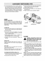
WARNING: This unit is equipped with an internal combustion engine and should not be used on or near any unimproved forest-covered, brush-covered or grass-covered land
unless the engine's exhaust system is equipped with a
spark arrester meeting applicable local or state laws (if any)
If a spark arrester is used, it should be maintained in effective working order by the operator
In the State of California the above is required by law
(Section 4442 of the California Public Resources Code).
Other states may have similar laws Federal laws apply on
federal lands A spark arrester for the muffler is available
through your nearest Sears Authorized Service Center
(See the REPAIR PARTS section of this manual )
TWOYEARLIMITEDWARRANTYON CRAFTSMANLAWNMOWER
For two years from the date of purchase, when this Craftsman Lawn Mower is maintained and lubricated
according to the instructions in the owner's manual, Sears will repair, free of charge, any defect in material and
workmanship,
If this Craftsman Lawn Mower is used for commercial
date of purchase.
purposes, this warranty applies for only 90 days from the
This warranty does not cover:
e Expendable items which become worn during normal use, such as blades, blade adapters, belts, air cleaners
and spark plugs,
e Repairs necessary because of operator abuse or negligence, including bent crankshafts and the failure to
maintain the equipment according to the instructions contained in the owner's manual
WARRANTY SERVICE IS AVAILABLE BY RETURNING THE CRAFTSMAN LAWN MOWER TO THE NEAREST SEARS SERVICE CENTER/DEPARTMENT
IN THE UNITED STATES, THIS WARRANTY APPLIES
ONLY WHILE THIS PRODUCT IS IN USE IN THE UNITED STATES
This warranty gives you specific legal rights, and you may also have other rights which may vary from state to
state.
SEARS, ROEBUCK AND CO. D/817WA, Hoffman Estates, IL 60179
TABLE OF CONTENTS
SAFETY RULES .......................................................... 2
PRODUCT SPECIFICATIONS ...................................... 3
WARRANTY .................................................................... 3
INDEX ............................................................................... 4
MOWER ACCESSORIES ............................................. 4
ASSEMBLY .............................................................. 5, 6
OPERATION ..................................................................6-9
CUSTOMER RESPONSIBILITIES ................................
9-11
SERVICE AND ADJUSTMENT ............................ 12, 13
STORAG E ................................................................... 14
TROUBLE SHOOTING ......................................................
15
REPAIR PARTS--MOWER
....................................16-t8
REPAIR PARTSiENGINE
.................................. 19-22
SLOPE GAUGE ................................................................23
PARTS ORDERING/SERVICE ................ BACK PAGE
nNDEX
A
G
P
Accessories .......................................... 4 Gasoline:
Primer ................................................. 8, 10
R
Storage ............................................... 14
Adjustments:
Carburetor ........................................ 12
Tank Capacity .........................................
7 Repair/Replacement
Parts ............. 16-22
Type .................................................... 7 Responsibilities, Customer ............ 9-11
Cutting Height .................................... 7
H
Rope Guide .......................................................
7
Engine Speed ...................................... 12
S
Handle Height .................................... 11 Handle:
Air Filter ............................................................
10
Height Adjustment ........................... 11 Safety Rules ................................................2
Storage ............................................. 14 Service and Adjustments:
Assembly .................................................5, 6
B
Blade ................................................ 10
L
Carburetor ......................................... 12
Belt Removal and Replacement....13, 14
Lubrication:
Blade:
Cutting Height ................................... 7
Replacement .................................. 10
Brake Spring Bracket ...................... 9
Engine ............................................
11
Sharpening .................................
10
Engine ...........................................................
10
Handle Height .............................
11
C
Rear Trail Shield .............................. 12
Wheel Adjusters ....................................9
Controls:
Wheels ................................................ 9 Service Recommendations ................... 9
Blade Control Handle ...........................7
M
Side Discharge Deflector ........................ 6
Engine Speed Control ......................... 7 Maintenance:
Spark Plug ............................................... 10
Cleaning .................................................. 11
Agreement .......................................................
3 Specifications ........................................... 3
Air Filter .................................................
10 Starting the Engine .......................................
Customer Responsibilities .........................9
8
Cutting Height .............................................7
Blade Care/Replacement ................. 10 Stopping the Mower ..................................
10
D
Engine ...................................................10 Storage ......................................................14
Lubrication ..................................... 9
T
Deflector, Side Discharge ........................6
Drive Clutch Adjustment ...................... 12
Spark Plug .................................. 10 Table of Contents .................................... 4
E
Schedule ............................................. 9 Trouble Shooting Guide ....................... 15
W
Engine:
Mulching and Mowing Tips ................... 8
Lubrication ........................................... 10 Mulching Plug ........................................... 6 Warranty ................................................. 3
O
Wheels:
Speed Control .......................................7
Starting ..............................................................
8 Oil:
Adjusting Height .....................................7
Storage ......................................................
14
Change ............................................. 10
Lubrication ......................................
9
F
Storage ....................................................
14
Filter, Air ................................................... 11
Type ..............................................................
g
Operating Mower .....................................
6, 7, 8
MOWER ACCESSORIES
These accessories were available when the mower was purchased, They are also available at most Sears retail
outlets, catalog and service centers Most Sears stores can order repair parts for you, when you provide the
model number of your mower,
MOWER
ENGINE
Spark
Plug
Air Filter
_luffler
_gine
Oil
Gas Can
Stabilizel
Grass Catcher
MOWER MAINTENANCE
Blade
Blade
Adapter
_hi
8
J_
4
ASSEMBLY
Retaining
Post
IMPORTANT:
This unit is shipped WITHOUT
GASOLINE or OIL in the engine. Be certain to service engine with gasoline and oil before operating
your mower.
NOTE: Reference to right or left hand side of the
mower is observed from the operating position°
TO REMOVEMOWERFROMCARTON
e Remove the carton inserts (if any), Remove the
owner's manual, side discharge chute and bottle of
oil which are in the carton Lift the mower from the
carton, or cut the corners of the carton and roll the
mower out.
NOTE: A grass catcher bracket is in the bag with the
owner's manual Keep this bracket in a safe place. If
you purchase the optional grass catcher, mount the
bracket on the right side of the upper handle as
shown on page 16 of this manual, key 10.
NOWTOSET-UPYOURLAWN MOWER
e Disconnect the spark plug wire from the spark plug
Ground the spark plug wire by attaching it to the
retaining post until ready to operate your mower.
See figures 1 and 2 (Spark plug wire is shown in
figure 1 without the rubber boot for clarity.)
e Remove any cardboard
pieces which may be
between the upper and lower handles for shipping
purposes.
e Pull up and back on the upper handle to raise the
handle into the operating position. Make certain the
lower handle is seated securely into the handle
mounting brackets, Tighten the hand knobs on
each side of the handle
NOTE: Your mower is shipped with the handle in the
higher height position If you wish to lower the height of
the handle, refer to the Adjustment Section at this time,
e Remove the hairpin clips from the outer hole in the
weld pins on the handle mounting brackets. Place
the hairpin clips in the inner hole,, See figure 3.
e The rope guide and wing nut are attached to the
starter rope, on top of the engine. Remove the wing
nut from rope guide. Remove the rope guide from
the starter rope
e With the spark plug wire disconnected and grounded, hold the blade control handle against the upper
handle, and pull the starter rope out of the engine.
Hold the rope guide as shown so the opening in the
rope guide is toward the front of mower. Slip the
rope guide around the starter rope and into the right
side of upper handle using the hole shown., Secure
using the wing nut. See figure 4.
e Make certain all nuts and bolts are tightened
securely. Also, be certain to reconnect the spark
plug wire before starting the mower.
Spark Plug
Wire
FIGURE '1.
\_
Rope"
.....
_
\_'-_---
Upper
'_,_
_"
_'
Starter
_
Lower
.and,e
\\ . J Hand,e
Mounting_
_ _
Bra_t_-
h_
_._.-_-X
/_---_
Spark Plug
-_,ii re and
Boot
Mulching
\\ "_'_ II_
FIGURE 2.
\
Handle
Mounting
Bracket
Lower
H_
Inner
Hole
Hairpin
Cl
Weld
Pin
FIGURE 3.
Wing Nut
RG
Guide
FIGURE 4,
Rope
_,,
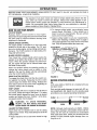
Yourmowerhasbeenshippedas a mulcher.Todischargegrasstotheside,proceedasfol!ows.
e To convert your mower from a mulcher to a
Mulching
Plug
side discharge mower, lift the mulching plug See
figure 5. Slide the two hooks on the side discharge
deflector under the hinge pin on the mulching plug
assembly. Lower the mulching plug
Hooks
FIGURE 5o
OPERATION
KNOWYOURLAWNMOWER
READ THIS OWNER'S MANUAL AND SAFETY RULES BEFORE OPERATING YOUR LAWN MOWER.
Compare the illustrations with your lawn mower to familiarize yourself with the location of various controls and
adjustments. Save this manual for future reference.
Engine
Control
Control
Handle
Drive
Cable
Handle
Guide
Rear Wheel
uster
Starter Ro
Muffler
LEFT SIDE OF MOWER
Oil Fill and D
Front
Wheel Adjuster
Deck
Mulc
Plug
_park
FIGURE 6.
Plug
Wire and Boot
MEETSCPSCBLADESAFETYREQUIREMENTS
Sears Walk-Behind Lawn Mowers conform to the safety standards of the American National Standards Institute,
and the U_S_Consumer Product Safety Commission. The blade turns when the engine is running.
BLADE CONTROL
HANDLE--must
be held down to
DRIVE CLUTCH CONTROL--must
be held against
the handle to engage the wheel drive. Release the
drive clutch control to stop the wheels from driving.
the handle to start and run the engine. Release to
stop the engine.
STARTER ROPE--used
for starting the engine
SHIFT LEVER--is used to select one of five operating speeds for the mower.
PRIMER...-pumps additional fuel from the carburetor
to the cylinder for use when starting a cold engine.
ENGINE SPEED CONTROL LEVER--permits
tion of fast or slow engine speed.
selec6
OPERATMON
BEFORE USING YOUR LAWN MOWER, AGAIN REFER TO THE "SAFETY RULES" AS SHOWN ON PAGE 2
OF THIS MANUAL° ALWAYS BE CAREFUL
The operation of any lawn mower can result in foreign objects being thrown into the
eyes, which can result in severe eye damage Always wear safety glasses or eye
shields before starting power tool operation or while performing any adjustments or
repairs. We recommend Wide Vision Safety Mask for over spectacles or standard
glasses available at Sears Retail or Catalog Stores..
HOWTO USEYOURMOWER
TO STOP ENGINE
Release
blade control
handle to stop engine.
Disconnect the spark plug wire and move it away from
the spark plug to prevent accidental starting while
equipment is unattended.
ENGINE SPEED CONTROL
The engine speed is controlled by a lever (red knob)
located on the left side of the engine_ The "HI" position is for starting engine, normal cutting and best performance The "LOW" position is for light cutting, trimming and fuel economy
BLADE CONTROL HANDLE
Your mower has a control handle which
operator to be behind the handle to start
mower When the operator releases the
dle, the engine will stop and an internal
the blade to stop quickly.
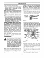
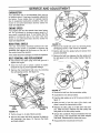
e To change cutting height, move adjuster levers
toward wheel& See figure 7. Move wheels up or
down to suit your requirements
Be sure all four
levers are in the same setting
e Adjust cutting height to suit your requirements..
Refer to the "Mulching or Mowing Tips" on page 9.
(The height adjusters may seem hard to move when
new. They will operate easier after some use )
Front Wheel
requires the
and run the
control hanbrake helps
When the operator leaves the operating position to
change the cutting height, pick up sticks or other
objects in the way, the engine will stop automatically
when the control handle is released.
DRIVE CLUTCH CONTROL
To engage the wheel drive, hold the drive clutch control against the handle. Releasing the drive clutch
control stops the wheels from driving. Release the
drive clutch control to slow down when negotiating an
obstacle, making a turn or stopping
SHIFT LEVER
The five speed shift lever is located on the left side of
the mower, beside the engine. See figure 7. To select
the mower speed, depress the lever, move to desired
position and release the lever. Position 1 is the slowest speed; position 5 is the fastest
WARNING:
TO AVOID
PERSONAL
INJURY,
DO NOT MOVE THE SHIFT
LEVER WHEN THE ENGINE IS RUNNING.
ADJUST CUTTING HEIGHT
Each wheel has an adjuster lever to set the cutting
height on your mower. They should always be set to the
same position.
e Raise wheels for low cut and lower wheels for high
cut
J
Rear Wheel
Adjuster
FIGURE 7.
BEFORESTARTINGENGINE
OIL
A 20 ounce bottle of SAE 30 oil is included with your
new lawn mower_
Only use high quality detergent oil rated with API service classification SG. Select the oil's viscosity grade
according to your expected operating temperature_
Colder
._
32°F _
5W30
m
_
Warmer
SAE 30
NOTE: Although multi-viscosity
oil (5W30, 10W30,
etc,) improve starting in cold weather, these multi-vis cosity oils will result in increased oil consumption
when used above 32°E Check your oil level more frequently to avoid possible engine damage from running low on oil.
OPERATION
e Place unit so engine is in a level position
e Remove oil fill cap and dipstick assembly Pour oil
slowly until oil level is to the FULL mark on dipstick
Crankcase capacity is approximately
1-1/4 pints
(20 ounces). DO NOT OVERFILL
NOTE: Crankcase oil should be changed after first
two (2) hours of operation and every twenty-five (25)
hours thereafter. Refer to ENGINE LUBRICATION
section.
e Replace oil fill cap and dipstick Tighten cap securely.
GAS
e Fill gas tank with about one (1) quart of clean,
fresh, lead-free grade automotive gasoline_ Lowlead or regular gasoline is an acceptable substitute.
DO NOT use Ethyl or high octane gasoline Be certain container is clean and free from rust or foreign
particles Never use gasoline that may be stale
from long periods of storage in the container_
WARNING: EXPERIENCE INDICATES THAT ALCOHOL BLENDED FUELS (CALLED GASOHOL OR
USING ETHANOL OR METHANOL) CAN ATTRACT
MOISTURE WHICH LEADS TO SEPARATION AND
FORMATION
OF ACIDS DURING STORAGE.
ACIDIC GAS CAN DAMAGE THE FUEL SYSTEM
OF AN ENGINE WHILE IN STORAGE. TO AVOID
ENGINE
PROBLEMS,
THE
FUEL
SYSTEM
SHOULD BE EMPTIED BEFORE STORAGE FOR
30 DAYS OR LONGER° USE FRESH FUEL NEXT
SEASON. SEE "STORAGE"
SECTION FOR ADDITIONAL INFORMATION.
In addition, the drive clutch may need to be loosened
when the unit is operated in fifth speed, ALWAYS
MAKE CERTAIN THE MOWER DOES NOT DRIVE
WITH THE DRIVE CLUTCH CONTROL HANDLE
RELEASED Refer to "Drive Clutch Adjustment"
further information.
for
e Connect spark plug wire to spark plug. Make certain the metal loop on the end of the spark plug
wire (inside the rubber boot) is fastened securely
over the metal tip on the spark plug, See figure 8
Metal Loop
on
Plug Wire
r Boot
FIGURE 8.
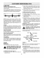
e Press primer button as follows (cold starts only)
For each initial start, push primer button five times
prior to starter operation See figure 9, Use sharp
pushes, wait between each push. Repeat the
above for each starter operation as necessary. Do
not use primer for warm engine restarts.
e Set engine speed control to "HI" speed,
Engine Speed
NEVER USE ENGINE OR CARBURETOR CLEANER PRODUCTS IN THE FUEL TANK OR PERMANENT DAMAGE MAY OCCUR.
TO STARTENGINE
WARNING:
WHEN STARTING
THE UNIT
FOR THE
FIRST(SLOW)
TIME, PLACE
MOWER
IN
FIRST
SPEED
POSITION.
FACE
THE MOWER AGAINST A SOLID OBJECT
SUCH AS A WALL, FENCE, ETC. START
THE UNIT, AND IF IT SHOWS ANY SIGNS
OF MOTION WITH THE DRIVE CLUTCH
CONTROL
DISENGAGED,
SHUT THE
ENGINE OFF IMMEDIATELY. ADJUST THE
DRIVE CLUTCH CONTROL AS INSTRUCTED IN THE ADJUSTMENT SECTION.
NOTE: The drive cable has been adjusted at the factory with the unit in third speed_ If the drive slips when
mower is operated in first speed, tighten the cable by
moving the adjustment wheel toward the inside of the
mower slightly as shown in figure 14 (Adjustment section)+
I
I
I
LOW
\
'
HI
FIGURE 9.
O
Hold blade control handle against upper handle.
See figure 10+ Grasp starter handle and pull rope
out slowly until engine reaches start of compression cycle (rope will pull slightly harder at this
point). Let the rope rewind slowly.
@
Pull rope with a rapid, continuous, full arm stroke
Keep a firm grip on start handle Let rope rewind
slowly. Do not let starter handle snap back against
starter
o If after three pulls the engine fails to start, push
primer five times, then pull starter rope again.
MULCHINGOR MOWINGTiPS
Blade Control
Handle
e For best results in normal and heavy mowing,
always run engine in "HI" speed position. "LOW"
speed is only for light cutting, trimming and fuel
economy.
@
The grass condition at the time of mewing determines the proper mower cutting height setting for
best lawn appearance. For a healthy lawn, always
cut one-third or less of the total length of the grass
at any one cutting.
0
Under certain conditions, such as very tall grass, it
may be necessary to raise the height of cut to
reduce pushing effort and to keep from overloading
the engine and leaving clumps of grass clippings
e For extremely heavy cutting, use a slow ground
speed, and reduce the width of cut.
FIGURE 10.
e Under heavy conditions cross cut for additional
mulching of surface debris.
CUSTOMER
RESPONSiBiLiTiES
GENERALRECOMMENDATIONS
•
In order to maintain the warranty on your mower,
the customer is expected to perform the maintenance as outlined below
e Once a year you should replace the spark plug, air
filter, and check blade for wear, A new spark plug
and air filter assures proper air-fuel mixture and
helps your engine run better and last longer,
MAINTENANCE
SCHEDULE
SERVICERECORD
SERVICEDATES
SCHEDULE
Fill in dates as you
complete regular service
After
Every
Use
Check Engine Oil
First
Two
Hours
Every
25
Hours
q
Lubricate Mower
Blade Care
,/
Change Engine Oil
,/
,/
q
Spark Plug Replaced
q
Air Filter Replaced
Cleaning
_/CHECK
q
CUSTOMER
RESPONSIB LRT ES
LUBRICATION
ENGINE OIL RECOMMENDATIONS
A 20 ounce bottle of SAE 30 oil is included with your
new lawn mower
e Use a block of wood between blade and mower
deck to prevent blade from turning when bolt is
removed. Protect your hands with gloves and/or
wrap blade with heavy cloth
Only use high quality detergent oil rated with API service classification SG. Select the oil's viscosity grade
according to your expected operating temperature.
Remove blade bolt by turning counterclockwise
Use a 9/16" box or open-end wrench
TO REPLACE BLADE (See Figure 11):
e Put blade adapter on engine crankshaft
Colder -,_
32°F
5W30
[]
_=- Warmer
e Fit blade in adapter. Be sure trailing edge of blade
is up towards engine.
e Assemble bolts, washers, and nuts in the exact
order of removal.
SAE 30
Q
NOTE: Although multi-viscosity
oil (5E30, 10W30,
etc.) improves starting in cold weather, these multiviscosity oils will result in increased oil consumption
when used above 32 ° F_ Check your oil level more
frequently to avoid possible engine damage from running low on oil
IMPORTANT: THE BOLT USED TO SECURE THE
BLADE TO ENGINE IS SPECIALLY HEAT-TREATED.
WHEELS
DO NOT SUBSTITUTE (SEE REPAIR PARTS).
DO NOT oil or grease the wheel bearings_ Viscous
lubricants will attract dust and dirt that will shorten the
DANGEROUS
AND MAY MAKE THE
CAUTION:
A LOOSE BLADE CAN BE
ENGINE HARD TO START,
life of the self-lubricating wheel bearings. If you feel
the wheels must be lubricated, use only a dry, silicone
type lubricant sparingly_
Use only a Sears authorized replacement blade to get
the best cutting results.
WHEEL ADJUSTERS
For easy operation, lubricate the wheel adjusters
least once a season with light oil.
Use block of wood to hold blade and tighten bolt
clockwise. The recommended torque for the center
is 450-600 in. Ibs. The recommended torque for the
blade adapter bolts is 200-350 in. IbsTorque
wrenches are available at most Sears stores and
through the catalog.
at
Nut--
BRAKE SPRING BRACKET
Spray a light oil lubricant on the brake spring bracket,
located on the right rear corner of the engine, at least
once a season.
.._..-Lock
Washer
Adapter--_
TRANSMISSION
The transmission is pre-lubricated and sealed at the
factory. It does not require checking. If disassembled
for any reason, fill with 2 ounces of Alvania grease,
part number 737-0168.
Blade Adapter___.._
asher
_<L_Center
Bolt
MOWER
FIGURE 11.
BLADE CARE
Your mower will work better with a sharp blade_
NOTE: We do not recommend
sharpening
blade--but if you do, be sure blade is balanced.
CAUTION: DISCONNECT
SPARK PLUG
WIRE FROM SPARK PLUG AND PLACE
WIRE WHERE IT CANNOT COME IN CONTACT WITH THE SPARK PLUG,
the
TO SHARPEN BLADE
• The blade can be sharpened with a file or on a
grinding wheel. Do not attempt to sharpen while on
the mower.
e Care should be taken to keep the blade balanced.
An unbalanced blade will cause excessive vibration
TO REMOVE BLADE (See Figure 11):
e Turn mower on its side. Make sure air filter and
when running and eventual damage to mower and
engine
carburetor are up.
10
CUSTOMER
RESPONSIBILITIES
@ Clean the inside of the cover and the collar with a
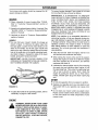
e To check blade balance, drive a nail into a beam or
wall. Leave about one inch of the straight nail
exposed. Place center hole of blade over the head
of the nail If blade is balanced, it should remain in
a horizontal position. If either end of the blade
moves downward, blade is not balanced. Sharpen
the heavy end until the blade is balanced.
clean cloth to remove any dirt accumulation.
® Insert new filter into cover_
® Put air filter cover and filter into collar aligning the
tab with the slot.
e Push in on cover and turn clockwise to tighten.
Collar
Clockwise
To Remove
ENGINE
ENGINE LUBRICATION
You must change the oil in the crankcase after the
first two (2) hours of operation and after each 25
hours of use thereafter, CHANGE THE OIL MORE
FREQUENTLY
IF USED IN SANDY OR DUSTY
CONDITIONS
Tab
Air Filter
_,,j Turn Clockwise
To Tighten
Air Filter Cover
FIGURE 12.
TO DRAIN OIL
e Disconnect spark plug wire from spark plug and
place wire where it cannot come in contact with plug
e Drain the gas tank
e Remove the oil fill cap and dipstick. Turn and tip
the unit on its side with the carburetor up, and drain
oil into a suitable container.
e Refill crankcase
with oil. Refer to "ENGINE
RECOMMENDATIONS"
OIL
on previous page.
e Replace oil fill cap and dipstick.
securely.
Tighten
CLEANING
cap
WARNING: DISCONNECT SPARK PLUG
WIRE FROM SPARK PLUG AND PLACE
WIRE WHERE IT CANNOT COME IN CONTACT WITH THE SPARK PLUG,
SPARK PLUG
Change your spark plug each year to make your
engine start easier and run better. Set spark plug gap
at 030 inch.
o Turn mower on its side with carburetor and air filter
up.
o Clean the underside of your mower after each use
AIR FILTER
Your engine will not run properly and may be damaged by using a dirty air filter..
0
Replace the air filter every year, more often if you mow
in very dusty, dirty conditions. Do not wash air filter.
TO CHANGE AIR FILTER (See Figure 12):
® Remove the air filter cover by turning counterclockwise to the stop and pull away from collar.
by scraping to remove build-up of grass clippings,
leaves, dirt or other matter. If this debris is allowed
to accumulate, it will invite rust and corrosion, and
may prevent proper mulching
Clean your mower and engine often to keep buildup of grass or debris from accumulating
around
engine. A clogged engine runs hotter and shortens
engine life.
NOTE: We DO NOT recommend using a garden hose
to clean mower unless the electrical system, muffler,
air filter and carburetor are covered to keep water out.
Water in engine can result in shortening engine life.
• Remove filter from inside of cover_
11
SERVICE AND ADJUSTMENT
moves forward with the drive clutch control released
(engine running), turn the adjustment wheel, located
on the left side of the mower at the upper end of the
drive clutch cable, toward the left to loosen the cable,
See figure 14. Recheck the adjustment as instructed
above,
CUTTINGHEIGHTADJUSTMENT
Refer to "ADJUST
section of manual
CU'FI'ING HEIGHT"
in operation
HANDLEHEIGHTADJUSTMENT
Your mower is shipped with the handle in the higher
height position, To lower the handle height, proceed
as follows.
Periodic adjustment may also be necessary due to
normal stretch and wear on the bell Adjustment may
be needed if the wheels seem to hesitate, but the
engine maintains the same speed To tighten the
cable, move the adjustment wheel toward the right
Recheck the adjustment. If additional adjustment is
required, loosen the drive cable as far as possible,
unhook the drive cable from the lower adjustment
hole in the control handle, and hook it in the upper
adjustment hole. Then readjust as instructed above
Always be certain to recheck the adjustment
e Remove the starter rope from the rope guide,
e Remove the upper handle by removing the hand
knobs and carriage bolts. Lay the upper handle out
of the way, being careful not to bend or kink the
cable_
e Remove the hairpin clips from the weld pins on the
handle brackets Press outward on the sides of the
lower handle, and remove it from the mower_
e Turn the lower handle around so the flat
tom is facing upward as shown in
Reassemble, placing the bottom holes
dle over the weld pins in the handle
bracket.
on the botfigure 13.
in the hanmounting
Adjustment
e Reassemble the upper handle.
Tighten
e Place the hairpin clips in the inner holes in the
weld pins and attach the starter rope as instructed
in the Assembly Section.
Loosen
Drive Ck
Cable
Lower-_'_
Handle
ustment
Wheel
"_1_,
FIGURE 14.
_Flat
FIVESPEEDSHIFTADJUSTMENT
FIGURE 13.
Periodic adjustment may be required due to normal
wear. Adjustment is needed if the shift lever cannot
be moved to all five positions,
DRIVECLUTCHADJUSTMENT
e Place the shift lever in high speed (5) position,
Refer to figure 7.
The correct drive clutch adjustment varies with the
speed of the mower, The drive clutch adjustment may
be checked as follows. Without starting the engine,
engage the drive clutch control (squeeze control lever
against the handle) and pull the mower backward
The wheels should lock Then release the drive clutch
O
Loosen the nut which is underneath
the side of the bracket).
O
Move the bracket to make certain it is loose. Then
slide it towards the rear of the unit as far as it will
the lever (on
control and pull the mower backward_ It should move
freely (or with only a small amount of resistance).
go, so that the pulley halves (beneath the deck) are
against each other. Make certain the belt does not
interfere.
If the wheels lock up when pulted backward with the
drive clutch control released (engine off), or if mower
e Tighten the nut underneath the lever to secure the
bracket in this position
12
SERVICE AND ADJUSTMENT
Remove
Center___._
CARBURETOR
Your carburetor has a non-adjustable fixed main jet
for mixture control It has been completely adjusted at
the factory If your engine does not operate properly
due to suspected carburetor problems, take your
mower to an authorized Sears Service Center for
repair and adjustment
ENGINESPEED
Your engine slow and fast speeds have been factory
set,, Do not attempt to increase engine speed or it
may result in personal injury, If you believe that the
engine is running too fast or too slow, take your
mower to an authorized Sears Service Center for
repair and adjustment
REARTRAILSHIELD
The rear
wheels of
possibility
the mower
FIGURE 16,
• Remove the inside belt cover by removing three
self*tapping screws, A 3/8" wrench is required,
trail shield, attached between the rear
your mower, is provided to minimize the
that objects wilt be thrown out the rear of
toward the operator.
e Roll the belt over the pulley half and remove from
around crankshaft.
If the shield becomes damaged, it should be replaced,
e Remove the belt from between the idler pulley and
the belt guard on the idler pulley brackeL See figure 17.
- _
Idler
Pull
BELTREMOVAL AND REPLACEMENT
e Disconnect
the spark plug wire and ground
against the engine
it
e Drain the fuel tank or place a piece of plastic
beneath the cap to prevent gasoline leakage.
Belt
Guard
Belt
e Remove the transmission belt cover by removing
five self-tapping screws, See figure 15.
Self-Tapping
Screws
t
L
\,
FIGURE 17.
e Remove the belt from the transmission pulley,
e Assemble the new belt as follows
• Push the idler pulley up out of the way as shown in
figure 17.
Trans
Belt
Cover
e Slide the belt in from the rear of the deck, and
place it around the transmission pulley,
Self-Tapping
Screws
• Release the idler pulley so it falls down into posF
tion_ Slide the belt in between the idler pulley and
belt guard on the idler pulley bracket,
FIGURE 15.
e Grease the crankshaft. Place belt between the two
pulley halves, and reassemble the blade adapter
and blade, Reassemble the inside belt cover.
e Tip the mower on its side. Block securely,
e Remove the center bolt which secures the blade to
the crankshaft, See figure 16, Remove the blade
and blade adapter,
e Reassemble the transmission belt cover.
13
STORAGE
Your mower and engine should be prepared for offseason storage as follows:
To prevent engine damage if lawn mower is not used
for more than 30 days, proceed as follows.
IMPORTANT:
IT IS IMPORTANT
TO PREVENT
GUM DEPOSITS FROM FORMING IN ESSENTIAL
FUEL SYSTEM PARTS SUCH AS CARBURETOR,
FUEL FILTER, FUEL HOSE, OR TANK DURING
STORAGE ALSO, FUEL (CALLED GASOHOL OR
USING ETHANOL OR METHANOL) CAN ATTRACT
MOISTURE WHICH LEADS TO SEPARATION AND
FORMATION OF ACID DURING STORAGE. ACIDIC
GAS CAN DAMAGE THE FUEL SYSTEM OF AN
ENGINE WHILE IN STORAGE
MOWER
e Clean underside of mower housing (See "CLEANING" in "Customer Responsibilities"
section of
manual).
e Inspect and replace/sharpen blade, if required (See
"BLADE CARE" in "Customer Responsibilities"
section of manual).
e Lubricate as shown in "Customer Responsibilities"
section of manual.
NOTE: Fuel stabilizer is an acceptable alternative in
minimizing formation of fuel gum deposits during storage. Add stabilizer to gasoline in fuel tank in fuel tank
or storage container. Always follow mix ratio found on
stabilizer container. Run engine at least 10 minutes
after adding stabilizer to allow stabilizer to reach the
carburetor. Do not drain gas tank and carburetor if
using stabilizer.
HANDLE
• You can fold your mower's handle for storage as
shown in figure 14. Remove the starter rope from
the rope guide. Loosen the two hand knobs on the
sides of the handle, and let the upper handle fold
down to the rear Move the hairpin clips to the outer
hole in the weld pins on the handle mounting brackets. Refer to figure 3 Spread the sides of the lower
handle, and push it forward and down.
e Drain the fuel tank Start the engine, and let it run
until fuel lines and carburetor are empty
e When storing the mower at the end of the season,
change the engine oil. Drain the oil after the engine
has been operated and is still warm, and refill the
crankcase with fresh oil
IMPORTANT:
WHEN FOLDING HANDLE FOR
STORAGE OR TRANSPORTATION, BE CAREFUL
NOT TO BEND OR KINK THE CABLES.
e Lubricate the piston/cylinder area by first removing
the spark plug and squirting clean engine oil into
the spark plug hole. Then cover the spark plug hole
with a rag to absorb oil spray. Next, rotate the
engine by pulling the starter two or three times
Finally, reinstall spark plug and attach spark plug
wire.
OTHER
e Do not store gasoline from one season to another
e Replace your gasoline can if your can starts to rust.
Rust and/or dirt in your gasoline can cause problems..
FIGURE 14.
e Do not store your mower under any plastic cover.
Plastic cannot breathe which allows condensation
e To place the handle in the operating position, refer to
"Assembly" on page 5 of this manual.
to form and cause the metal components
mower to rust.
ENGINE
&
WARNING: NEVER STORE YOUR LAWN
MOWER INDOORS OR IN AN ENCLOSED,
POORLY VENTILATED AREA IF GASOLINE REMAINS IN THE TANK. FUMES
MAY REACH AN OPEN FLAME, SPARK
OR PILOT LIGHT FROM A FURNACE,
WATER HEATER, CLOTHES
DRYER,
CIGARETTE, ETCo
14
of your
TROUBLE SHOOTING GUIDE
Trouble
Possible Cause(s)
Corrective Action
Engine fails to start
1.
2
3
4
5
&
7
1,
2,
3,
4.,
&
6.
7,
Engine runs erratic
1. Spark plug wire loose
2 Blocked fuel line or stale fuel
Blade control handle disengaged
Spark plug wire disconnected,
Throttle control lever not in starting position
Fuel tank empty, or stale fuel
Blocked fuelline.
Faulty spark plug
Engine flooded
3, Vent in gas cap plugged.
4. Water or dirt in fuel system
5, Dirty air cleaner,
Engine overheats
Occasional skip
(hesitates) at high speed
1. Engine oil level low.
2_ Air flow restricted.
Engage blade control handle,
Connect wire to spark plug
Move throttle lever to starting position.
Fill tank with clean, fresh gasoline
Clean fuel line.
Clean, adjust gap or replace
Remove spark plug, dry the plug, and
crank engine with plug removed and
throttle in off position Replace spark
plug, connect wire and resume starting
procedure&
1 Connect and tighten spark plug wire
2. Clean fuel line; fill tank with clean,
fresh gasoline,
& Clear vent
4 Drain fuel tank Refill with fresh fuel
5 Clean air cleaner See "Customer
Responsibilities" section of this manual
1 Fill crankcase with proper oil
2, Clean lawn mower engine.
Spark plug gap too close.
Adjust gap to 030'L
Idles poorly
1, Spark plug fouled, faulty or gap too wide.
2, Dirty air cleaner.
1 Reset gap to 030" or replace spark plug
2 Clean air cleaner See "Customer
Responsibilities" section of this manual.
Excessive vibration
1 Cutting blade loose or unbalanced,
1 Tighten
Balance
2, Replace
3. Contact
2_ Bent cutting blade.
3_ Bent engine crankshaft
Mower will not
mulch grass
1 Engine speed too low
2 Wet grass,
1_ Move throttle lever to FAST positiOnr
2 DO not mow when grass is wet; wait until
later to cut
3 Mow once at a high cutting height, then
mow again at desired height or make a
narrower cutting swath (1/2 width),
Do not cut off more than 1/3 of the total
length of the grass at any one cutting
4, Sharpen or replace blade_
3. Excessively high grass
4_ Dull blade.
Uneven cut
1 Wheels not positioned correctly.
2o Dull blade
Mower propels with
clutch disengaged
Mower will not propel
blade and adapter.
blade
blade
your SEARS Service Center
Drive clutch control adjustment needed
1_ Belt has stretched; drive clutch control
adjustment needed,
2. Wet grass.
1. Place all four wheels in same
height position
2, Sharpen or replace blade.
Adjust drive clutch control See "Service
and Adjustment" section of this manual.
1. Adjust drive clutch control. See "Service
and Adjustment" section of this manual
2 Do not mow when grass is wet; wait
until later to cut.
Note: For repairs beyond the minor adjustments listed above, contact your nearest SEARS Service Center
15
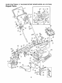
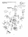
SEARS CRAFTSMAN
21" MULCHING ROTARY MOWER MODEL NO. 247.372650
Repair Parts
78
40
36
52
63
121
32
65
7
147
8
42
45
/
102
\
51
69"
81
11 80 \
.86
20
55
17 56
60
16
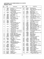
SEARS
CRAFTSMAN
21"
MULCHING
ROTARY
MOWER
MODEL
NO. 247.372650
Repair Parts
KEY
NO,
PART
NO,
1
2
3
4
6
7
8
10
11
I2
13
14
16
17
18
20
21
22
23
720-0226
747-0824
q0-1205
712-0397
747-0855
736-0329
712-0287
782-7007
731-0981A
710-0605
746-0875
749-0539B
731-1407
731-1404
714-0104
747-0710
782-7006
732-0731
682-7000
24
25
27
28
29
3O
31
32
33
34
35
36
736-0270
710-0167
16855
782-7009
_712-0324
_714-0507
736-0278
735-0639
i682-7511
i747-0883
749-0928
143,434132
KEY
NO.
DESCRIPTION
37
38
39
4O
41
42
43
44
45
46
47
48
682-7514
731-1137
726-0287
782-7560
732-0724
682-7513
710-0352
736-0270
710-0351
720-0190
712-0296
713-0361
49
51
52
53
55
56
57
58
720-0241
731-1421
726-0240
782-7559
753-0519
742-0721
732-0719
736-0453
Grip
Control Handle
Rope Guide
Wing Nut 1/4-20 Thd
Belt Guard
L-Wash, 1/4" I.D.*
Hex Nut 1/4-20 Thd.*
Grass Catcher Bracket
Hub Cap
Oval C-Sunk Mach,, Scr_
Throttle Body
Upper Handle
Side Chute Deflector
Mulch Plug
Internal Cotter Pin 5/16" Dia.
Hinge Pin
Plug Adapter
Torsion Spring
Mulch Plug Ass'y. Comp.
(Incl, Ref 17.20.21,22)
Bell-Wash. _265" I.D_ x .75" O.D.
Carriage Bolt 1/4-20 x 5" Lg
Pawl Plate
Chute Stop Bracket
Hex L-Nut 1/4-20 Thd,
Cotter Pin 3/32" Di& x ,75"
FI-Wash, 328" I.D, x 68"
Spark Plug Insulator
Lower Pulley Half Ass'y,
Shift Rod
Lower Handle
Engine--Craftsman
Model
143,434132
Housing Ass'y
Flanged Bushing
Clamp
Shift Adj, Plate
Shift Lever
Chain--Axle Ass'y.
Hex B-Tap Scr. 1/4" x 38"
Bell-Wash, 1/4" I,D
Truss Mach B-Tap Scr. #10 x 5"
Sping Lever Knob
Hex Patch L-Nut 3/8-24 Thd.
#48 Chain ,500" Pitch x 38
Links
Hand Knob
Rear Flap 3 75" x 17,5" Lg.
Cable Tie
Drive Control Bracket
Blade Adapter Kit
21" Mulching Blade
Torsion Spring
Bell-Wash, ,47" I.D. x 1_14"
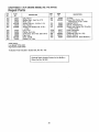
6O
710-0561
Hex Bolt 7/16-20 x 2.5"
*Common Hardware--May
NOTE: Specifications
or obligation
61
62
63
64
65
66
67
68
69
70
71
72
73
74
75
76
77i
78i
791
PART
NO.
748-0190
782-7563
736-0451
682-3006A
682-3007A
710-0260
710-0603
710-0654A
712-0267
720-0230
732-0725
738-0138
736-0242
750-0736
750-0624
736-0289
712-0291
712-0158
710-0653
80
81
82
64
86
95
96
98
99
100
101
102
115
121
122
127
128
129
130
131
134
136
138
140
147
148
'149
152
738-0137
748-0188B
734-1510B
741-0486B
712-0414
746"0911
754-0343
711-0313
710-1055
712-0241
736-0169
782-0023
747-0884
710-1174
711-0805
756-0976
712-0711
746-0737
748-0318
714"0115
741-0522
10622B
682-7506
710-0599
738-0864
741-0324
736-0160
710-0751
153
618-0055
154
155
--
I6500A
736-0300
770-8274H
Be Purchased Locally.
subject to change without notice
'17
DESCRIPTION
Spacer ,513" ID.
Bracket--Shift Plate
Saddle Washer ,32" ID
RH Handle Wheel BrkL Ass'y,
L,H, Handle Wheel Brkt Ass'y,
Carriage Bolt 5/16-18 x _62"*
Hex B-Tap Scr. 5/16-18
Hex TT-Tap Scr 3/8-16
Hex Nut 5/16-18 Thd,*
Grip
Height Adj, Lever
Shl& Bolt 437" Dia.
Bell-Wash. 5/16" LD
Spacer 383" I.D
Shld Spacer 5" Dia,
Shld. Spacer ,5" Dia., x 134"
Hex L-Nut 1/4-20 Thd,
Hex L-Nut 5/16-18 Thd,
Hex Wash Hd, Tap Scr 1/4-20
x ,38" Lg.
Shld. Scr 342" Dia, x 268
Pawl
Wheel Ass'y. Comp,--Rear
Sleeve Bearing 1/2" ID.
Weld Top L-Nut 1/4-20 Thd
S,P, Cable
"V"-Belt
Sleeve ,526" ID.
Hex Bolt 3/8-24 x 1.0" Lg,
Hex Nut 3/8-24 Thd,
L-Wash. 3/8" I D
21" Deck Ass'y.
Self-Propelled Control Lever
Curved Hd, Bolt 5/16-18 x 2" Lg,
Shld Pin 143" Lg,
Pulley Half--Serrated
Hex Jam Nut 3/8-24 Thd,*
Control Cable---51"
Ratchet Wheel 1.62" O.D,
Cotter Pin 1/8" Dia, x 1"*
Hex Flange Bearing
Spring--Nylon
Chain Cover Ass'y,
Hex TT-Tap Scr, 1/4-20 x ,50"
Rear Shaft Ass'y 21.44" Lg,,
Hex Flange Brg, .506" I.D.
FI-Wash..531" I,D, x .930"
Hex Bolt 1/4-20 x 62" Lg
(Grade 5)
Transmission Comp
(See Breakdown)
Hex Bearing Cup
Fl-Wash 385" I,D. x ,87" O.D.
Owner's Manual
SEARS
CRAFTSMAN
21" MULCHING
ROTARY MOWER
MODEL
NO. 247.372650
Repair Parts
54
5O
-
KEY
NO.
PART
NO,
1
2
3
4
5
6
7
8
710-1062
736-0329
717-0418A
713-0400
736-0336
741-0413
I6500A
736-0314
9
741-0479
11
12
13
15
16
17
18
19
20
21
22
24
25
26
27
28
29
30
31
32
717-1216
748-0208A
721-0212
756-0330A
736-0270
712-0351
738-0440
736-0344
738-0826
756-0558
741-0556
17052A
712-0138
732-0357
717-0419A
741-0415
717-0422A
741-0414
721-0213
738-0607A
tPart of Transmission
DESCRIPTION
KEY
NO.
33
34
35
36
37
38
39
40
42
43
44
45
46
47
48
49
5O
51
54
56
57
58
59
60
63
64
65
66
67
7O
Hex Patch Bolt 1/4-20 x 125"t
L-Wash, 1/4" I.D.*
Upper Hsg, Half1#48 Sprocket 7 T x 1/2 Pitcht
FI-Wash. 5/8" I,D. x .0301Hex Flange Brg .631" I.D,t
Hex Bearing Cupt
Thrust Wash, .382" ID x
.70" O,D.t
Thrust Bearing ,375" I,D, x
812" O,D,t
11 Tooth Pinion ShafflFlange Bearingt
Oil Sealt
FI-Pulley 5.06" O,D.
Bell-Wash..265" I.D_ x .75"
Hex L-Nut 1/4-28 LH. Thd.
Shld, Spacer 375" Dia. x. 170
FI-Wash..390" I.D. x 1,0"
Shld. Bolt 375" Dia. x .40"
Fl-ldler Plastic 1.50" Dia.
Needle Brg. 375" x 31
Idler Brk't. Ass'y.
Hex Patch L-Nut 1/4-28 Thd,
Extension Spring 1,12" Lg,
Lower Hsg. Halft
Flange Bearing .566 Dia,t
33 Tooth Helical Geart
Flange Bearing .629 Dia,t
Oil Seal .625 Dia,l*
Gear Sprocket Shaftt
Complete, Ref, No 36
18
PART
NO.
736-0722
710-0436
736-0410
618-0055
738-0102
734-1512A
736-0105
710-1241
741-0492A
17733
782-0516
710-0653
720-0190
732-0639
731-1281
710-0352
782-7558
710-0599
782-7554
710-1242
736-0242
731-0981A
746-0909
736-0222
712-0147
710-1003
710-0167
710-0603
712-3027
736-0329
DESCRIPTION
L-Wash. #10 LD.t
Hex B-Tap Scr, #10 x ,62"t
Hex Washer 26" x 88"
Transmission Comp,
Front Axle Bolt
Wheel Ass'y. Comp. 8 x 2"
Bell-Wash..380"
I.D. x .88
Hex Wash, Hd. Scr. 1/4 x 1" Lg,
Block Bushing
Axle Ass'y.
Height Adj Bracket
Hex TT-Tap Scr, 1/4-20 x ,38"
Knob
Spring Lever
Plastic Front End
Hex B-Tap Scr, 1/4" x ,38"
Belt Cover
Hex Wash. Hd. TT-Scr, 1/4-20
Transmission Belt Cover
Torx Truss Hd Scr. 5/16 x ,75"
Bell-Wash, ,345" LD x .88"
Hub Cap
S,P, Cable
External L-Wash. 1/4" I,D
Speed Nut #10-24 Thd.
Hex Tap Scr. #10-16 x 5" Lg.
Carr. Bolt 1/4-20 x .5" Lg,
Hex B-Tap Scr. 5/16-18 x .5"
Hex Flange L-Nut 1/4-20 Thd
L-Wash. 1/4" LD.*
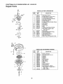
CRAFTSMAN
5 H.P. ENGINE
MODEL
NO. 143.434132
Repair Parts
o.
I
I
I
.+
1
i
I
NODELandSERIALD_..
1
NUMBERSHERE "_1
_
292
135
_l+-+2s2
101
126
120
119
125
/
306
241
<
245
238
19
CRAFTSMAN
5 H.R ENGINE
MODEL
NO. 143.434132
Repair Parts
KEY
NO,,
PART
NO,,
1
2
6
7
36265
26727
33734
34214A
8
9
*33735
30200
12A
12B
14
15
16
17
18
33886
34695
28277
30589
31383A
31335
650548
19
20
3O
40
36281
32600
35606
36073
40
36074
4O
36075
41
36070
41
36071
41
36072
42
42
42
43
45
36076
36077
36078
20381
30963B
46
48
5O
32610A
27241
35992
52
69
70
29914
*35261
34311D
72
75
8O
81
82
36083
27897
30574A
30590A
30591
83
86
30588A
650488
89
90
92
93
611004
611112
650815
650816
DESCRIPTION
KEY
NO.
Cylinder Ass'y (Incl Nos 2 & 20)
Pin, Dowel
Element, Breather
Breather Ass'y. (IncL Nos. 6, 8,
9, 12A & 12B)
Gasket, Breather
Screw, Hex Washer Hal. Self-Tap
Sems, 10-24 x 9/16
Tube, Breather
Elbow, Breather Tube
Washer, Flat
Rod, Governor (IncL No. 14)
Lever, Governor
Clamp, Governor Lever
Screw, Hex Washer Hd.,
8-32 x 5/16
Spring, Extension
Seal, Oil
Crankshaft Ass'y.
Piston, Pin & Ring Ass'y. (Std.)
(IncL Nos. 41,42 & 43)
Piston, Pin & Ring Ass'y.
(.010 Oversize)
(IncL Nos. 41, 42 & 43)
Piston, Pin & Ring Ass'y.
(.020 Oversize)
(IncL Nos. 41,42, & 43)
Piston & Pin Ass'y. (Std.)
(IncL No_43)
Piston & Pin Ass'y. (.010 Oversize)
(Incl. No. 43)
Piston & Pin Ass'y. (020 Oversize)
(Incl. No. 43)
Ring Set, Piston (Std.)
Ring Set, Piston (.010 Oversize)
Ring Set, Piston (.020 Oversize)
Ring, Piston Pin Retaining
Rod Ass'y, Connecting (lncl.
No. 46)
Bolt, Connecting Rod
Valve, Lifter
Camshaft (Mech Compression
Release)
Pump Ass'y., Oil
Gasket, Mounting Flange
Flange, Mounting (IncL Nos. 72,
75, 80, 81,82 & 83)
Plug, Oil Drain
Seal, Oil
Shaft, Governor
Washer, Flat
Gear Ass'y., Governor (IncL
No. 81)
Spool, Governor
Screw, Hex Hd. Sems, 1/4-20 x
1-1/4
Key, Flywheel
Flywheel
Washer, Belleville
Nut, Flywheel
2O
PART
NO,
100
101
103
34443A
610118
650814
110
119
120
125
34961
33554A
34342
29313C
125
29315C
126
126
29314B
29315C
130
6021A
135
35395
150
151
166
169
172
174
178
182
184
185
186
189
35991
31673
35827
"27234A
32755
650128
29752
6201
*26756
31384A
34337
650839
190
191
192
193
194
195
200
35831
35039B
34966
34965
32309
610973
35727
202
203
204
2O5
207
209
33802
31342
650549
650777
34336
30200
215
223
224
238
35511
650451
"34690A
650932
239
241
245
250
260
261
*34338
35797
35066
35065
35826
30200
262
650831
DESCRIPTION
Solid State Ass'y
Cover, Spark Plug
Screw, Torx T-15 Hex Washer Hd.
Seres, 10-24 x 1
Wire, Ground
Gasket, Cylinder Head
Head, Cylinder
Valve, Exhaust (Std) (Incl
No. 151)
Valve, Exhaust (1/32" Oversize)
(Inct No 151)
Valve, Intake (Std.) (Incl. No. 151)
Valve, Intake (1/32" Oversize)
(Incl. No. 151)
Screw, Hex Flange Hd., 5/16-18 x
1-1/2
Spark Plug, Resistor (Champion
RJ-19LM or equivalent)
Spring, Valve
Cap, Lower Valve Spring
Shroud, Engine
Gasket, Valve Spdng Box
Cover, Valve Spring Box
Screw, Hex Hd Seres, 10-24 x 1/2
Nut & Lock Washer, 1/4-28
Screw, Hex Hd Cap, 1/4-28 x 7/8
Gasket, Carburetor
Pipe, Intake (IncL No. 224)
Link, Governor Spring
Screw, Hex Hd. Sems Powedok,
1/4-20 x 3/8
Lever, Brake
Bracket, S.E. Brake (IncL No_ 195
Link, Control
Spring, Extension
Ring, Retaining
Terminal Ass'y.
Bracket Ass'y, Control (IncL
No. 202 thru 205)
Spring, Compression
Spring, Compression
Screw, FiL Hd. 5-40 x 7/16
Screw, Fil. Hd., 6-32 x 21/32
Link, Throttle
Screw, Hex Washer Hal, Self-Tap
Sems, 10-24 x 9/16
Knob, Control
Screw, Hex Hd. Sems, 1/4-20 x 1
Gasket, Intake Pipe
Screw, Hex Washer Hd Shoulder
10-32 x 49/64
Gasket, Air Cleaner
Collar, Air Cleaner
Filter, Air Cleaner (Paper)
Cover, Air Cleaner
Housing, Blower
Screw, Hex Washer Hd. Self-Tap
Sems, 10-24 x 9/16
Screw, Hex Washer Hd. Powerlok
Thread, 1/4-20 x 15/32
CRAFTSMAN
5 H.P. ENGINE
MODEL
NO. 143.434132
Repair Parts
KEY
NO.
263
PART
NO.
275
276
277
285
267
35821
34613
33753
650795
35000
650926
290
292
300
301
305
306
34357
26460
35586
35355
35819A
*34265
DESCRIPTION
Grill, Recoil
Muffler Ass'y. (Incl No 277)
Plate, Lock
Screw, Hex Hd., 1/4-20 x 2-1/4
Hub, Starter
Screw, Hex Washer Hd., 8-32 x
21/64
Line, Fuel
Clamp, Fuel Line
Tank Ass'y (IncL Nos. 292 & 301)
Cap, Fuel
Tube, Oil Fill
Gasket, Fill Tube
KEY
NO,
PART
NO.
307
309
35499
650936
310
313
347
35822
34080
650898
370A
370C
380
390
400
35977
35167
632644
590637
35997
RPM Setting:
Low Speed: 2750-3050
High Speed: 3200-3400
*Indicates Parts included in Gasket Set, Ref. No. 400
Optional Spark Arrester Screen for the Muffler-Order Part No. 391022.
21
DESCRIPTION
"O"-Ring
Screw, Hex Washer Hd
Shakeproof, 10-32 x 13/32
Dipstick, Oil Fill
Spacer, Flywheel Key
Screw, Hex Washer Hd Shoulder,
10-32 x 27/32
Decal, Instruction
Decal, Throttle
Carburetor (IncL No 184)
Starter, Rewind
Gasket Set (Incl Items Marked *)
CRAFTSMAN
5 H.P. ENGINE
MODEL
NO. 143.434132
Repair Parts
PARTS
KEY
NO,
35
PART
NO,
-1
2
4
5
6
7
16
25
27
28
29
30
632644
631615
631767
631184
631183
632590
650506
632527
631867
631024
632019
631028
631021
31
35
35Ai
40
44
48
631022
36045
632647
632578
27110
631027
LIST FOR CARBURETOR
DESCRIPTION
Carburetor Comp
Throttle Shaft & Lever Ass'y_
Throttle Return Spring
Dust Seal Washer (Throttle)
Dust Seal (Throttle)
Throttle Shutter
Throttle & Choke Shutter Screw
Fuel Fitting
Float Bowl
Shaft, Float
Float
O-Ring, Float Bowl to Body
Inlet Needle, Seat & Clip
(Incl, No, 3'1)
Spring Clip
Primer Bulb/Retainer Ring
Primer Bulb Filter
High Speed Bowl Nut
Bowl Nut Washer
Welch Plug, Atmospheric Vent
PARTS LIST FOR REWIND STARTER
KEY
NO.
22
PART
NO.
1
2
3
4
5
6
7
8
9
10
11
12
590637
590599A
590600
590615
590601
590598
590616
590617
590618
590619
590620
590638
590535
13
590452
DESCRIPTION
Starter, Rewind
Pin, Spring (IncL No, 4)
Washer
Retainer
Washer
Spring, Brake
Dog, Starter
Spring, Dog
Pulley
Spring, Rewind
Cover, Spring
Housing Ass'y,, Starter
Rope, Starter (Length 98" &
9/64" Dia.)
Handle, Starter
USE THiS PAGE AS A GUIDE TO DETERMINE
g
8_
B
B
..................
SLOPES WHERE YOU MAY NOT OPERATE
SAFELY.
SIGHT AND HOLD THIS LEVEL WITH A VERTICAL TREE
8_
B
.......
A POWER POLE
__.=_ .......
Q
U
"
_
-
A CORNER OF A BUILDING
n
H_
0
.....
OR A FENCE POST
...... :?_oo
-
.
-
-.......
°
6
..... _/NE
n
o°°°,
B
,,_
Plr_-p_p_
"...._
15o ,.,.
°°oe
°=teooeDgeeei
g
15 °
WARNING
Do not mow on inclines with a slope in excess of 15 degrees (a rise of approximately 2-1/2 feet every 10 feet). If
operating a walk-behind mower on such a slope, it is extremely difficult to maintain your footing and you could
slip, resulting in serious injury.
Operate WALK-BEHIND
mowers across the face of slopes, never up and down slopes.
OWHER'
MAHUAL
5.0 HORSEPOWER
21" POWER PROPELLED
5=SPEED "3=1N-1"
MULCHING ROTARY MOWER
MODELH0.
247.372650
Each lawn mower has its own model number,
has its own model number,
Each engine
The model number for your lawn mower will be found on a
label attached
to the lawn mower on the top rear of the
deck.
The model number for the engine will be found on the
blower housing of the engine adjacent to the spark plug,
All parts listed herein may be ordered
through
Sears,
Roebuck and Co. Service Centers and most Retail Stores.
WHEN ORDERING REPAIR PARTS, ALWAYS GIVE THE
FOLLOWING
INFORMATION:
TOORDER
REPAIRPARTS
* PRODUCT-
"21" Mulching
* MODEL
NUMBER
* ENGINE
MODEL NUMBER
Rotary Mower"
- 247.372650
- 143.434132
* PART NUMBER
* PART DESCRIPTION
Your Sears merchandise
has added value when you consider that Sears has service units nationwide
staffed with
Sears trained technicians_.professional
technicians
specifically trained on Sears products, having the parts, tools and
the equipment to insure that we meet our pledge to you...we
service what we sell.
SEARS, ROEBUCK AND CO., Hoffman Estates, IL
770-8274H
1/93
60179
U.S.A.
Printed in U.S.A.