1
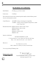
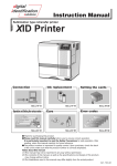
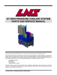
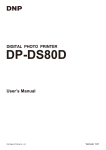
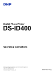
DNP
Instructions
Card Laminator
Model
Name
CL-500
Installation
Setting Film
Operation and Settings
>>cleaning OK?
>Cleaning
Power save 60
>Mode:Single
MENU
Ready
See pages 8 - 10
Error Messages
See pages 11 - 12
See pages 13 - 14
Maintenance
Tu r n o v e r e r r o r
Card Jam (Out)
HR Overheat
Overcool
No Cassette
See page 17
See pages 19 - 20
● Thank you for purchasing our product.
● Before operating this unit, please read the instructions carefully to ensure the best possible performance.
Be sure to read “Notes for safe operation” and use the unit safely. Keep the instruction manual in a safe place
and read it when necessary.
● The manufacturing number is important for quality control. Please check whether the manufacturing number on
the back of this unit is correct during the purchase.
Notes regarding this manual
(1) The contents of this manual shall not be reprinted or redistributed in any form without prior consent.
(2) The contents of this manual or the specifications and external appearance of this unit may be altered
without prior notice.
(3) Illustrations used in this manual may differ slightly from the actual shape of this unit.
KAT- T173-002
Declaration of Conformity
Model Number:
CL-500yyyyy(y=A-Z,0-9 or blank)
Product name:
Card Printer
We herewith declare that the above mentioned product complies with the following council
directives and harmonized standards.
Council Directives:
89/336/EEC relating to electromagnetic compatibility.
73/23/EEC relating to electrical equipment designed for use within
certain voltage limits.
Harmonized Standards: EN55022:1994+A1:1995+A2:1997: Class B
EN55024:1998+A1:2001+A2:2003
EN61000-3-2:2000
EN61000-3-3:1995+A1:2001
EN60950-1:2001
Importer and distributer:
DAI NIPPON PRINTING CO.,LTD.
1-1 Ichigaya-kagocho, 1-chome Shinjuku-ku, Tokyo 162-8001 Japan
Phone: +81-3-3266-3344 Facsimile: +81-3-3266-2732
Manufacture
Victor Data Systems Co.,Ltd.
2969-2, Ishikawa-cho, Hachioji-shi, Tokyo 192-8620 Japan
Year to begin affixing CE Marking: 2004
Hachioji-shi, Dec.21.2004
Place,
Date
Tateki Hisanaga General Manager-Quality Control
Victor Data Systems Co., Ltd.
2
Information for USA
NOTE:
This equipment has been tested and found to comply with the limits for a Class B digital device, pursuant to part 15 the FCC Rules. These limits are designed to provide reasonable protection against harmful interference in a residential installation. This equipment generates, uses and can radiate radio frequency energy and, if not installed and used in accordance with the instructions, may cause harmful
interference to radio communications. However, there is no guarantee that interference will not occur in
a particular installation. If this equipment does cause harmful interference to radio or television reception, which can be determined by turning the equipment off and on, the user is encouraged to try to
correct the interference by one or more of the following measures:
– Reorient or relocate the receiving antenna.
– Increase the separation between the equipment and receiver.
– Connect the equipment into an outlet on a circuit different from that to which the receiver is connected.
– Consult the dealer or an experienced radio/TV technician for help.
Caution: Changes or modifications not approved by party responsible for compliance could void user's authority
to operate the equipment.
Machine noise
Sound power level: less than 70dB(A) according to DIN45635 part 19 (EN27779).
The measurements are to be made according to DIN45635 part 2019 or EN27779, respectively.
3
Introduction
Characteristics of this Unit
● This is a laminating machine connected to a card printer, whereby it adheres a protective layer over the surface of
a card printed by the printer.
● A hologram can be created on the adhesive protective layer, thus increasing the security level of the card.
● It is not necessary to control this unit via the printer as it receives and laminates the card automatically according to
settings.
● Connecting a communication cable between this unit and the printer permits communication with the printer.
Table of Contents
Notes for safe operation ............................................ 5
Before Using ............................................................... 7
Checking accessories ............................................... 7
Handling the film ....................................................... 7
Cards that can be used ............................................. 7
Location for installation ............................................. 7
Installation .................................................................. 8
Part Names ............................................................... 8
How to install ............................................................. 8
Mounting the Stacker ................................................ 9
Setting the Voltage toggling switch ........................... 9
Connecting the Power Cord ...................................... 9
Installing a cable between units .............................. 10
Preparation and Starting ......................................... 11
Mounting the Film ................................................... 11
Power On ................................................................ 12
Exchange the film ................................................... 12
Operation and Settings ............................................ 13
Control Panel Display and Operation ...................... 13
User Mode Settings ................................................ 14
Troubleshooting ....................................................... 15
Internal Structure .................................................... 15
Settings for Laminate Condition .............................. 16
Error Code List ........................................................ 17
Removing Jammed Card ........................................ 18
Improper winding of film .......................................... 18
Film discoloration .................................................... 18
Maintenance ............................................................. 19
Cleaning the Transport Roller (Cleaning Card) ....... 19
Cleaning the Filter ................................................... 19
Cleaning the cassette ............................................. 20
Once Laminator servicing and cleaning have been
completed ............................................................... 20
Specifications ........................................................... 21
4
Notes for safe operation
Before you use
Read these notes on safety thoroughly before operating your printer in order to use the unit properly. Once you start
using the unit, this manual should be put aside the unit, or at a convenient place where you can look up the manual any
time as you need.
WARNING
CAUTION
● If you ignore the warning with this mark, and handle
the unit in a wrong way, death or serious injuries may
occur.
● If you ignore the caution with this mark, and handle
the unit in a wrong way, injuries or damages to
properties may occur.
WARNING
䡵 If the abnormal phenomena as listed below are
seen, immediately stop operating the unit.
Continuing operation may cause a fire or electric
shock.
• Smoke or odd smell comes out from the machine.
• Water or metal went into the machine.
• The unit fell to the floor, or the cabinet was broken.
• The power cable is damaged (exposed lead, broken
cable, etc.)
If you see these phenomena, turn off the power, pull out the
power plug, and contact your dealer as soon as possible. Do
not try to repair it by yourself. It is dangerous.
䡵 Do not remove the screws, or disassemble or
alter the machine.
• High-voltage components are contained in the unit.
Touching these areas may result in an electric shock.
• Ask your dealer if you want the unit inspected or repaired.
• Do not remove the external covers of the machine. You
may get an electric shock.
䡵 Do not work on the power cable, or give
excessive force on it. Do not put heavy objects
such as furniture on the cable.
• The cable may be damaged, causing a fire or electric
shock.
• When you find a defect on the power cable, such as
exposed lead, stop using the unit, and consult your
dealer.
䡵 Do not use the machine with the power plug
inserted incompletely.
• The machine generates heat due to incomplete contact,
causing a fire or electric shock.
• Do not put many cords on a single plug socket. The
power cords also heats up.
䡵 Do not use the machine with dusts piled on the
power plug. Do not put a metallic material
adjacent to the power plug.
• Dusts and metal are conductive, causing a fire or electric
shock.
• Pull out the power plug from the outlet every six months,
and clean the dusts piled on the legs and body of the
plug.
䡵 Do not use a line voltage other than instructed.
• Using a line voltage or power supply which is not
specified may cause a fire or electric shock.
䡵 Do not put foreign materials from the openings
of the machine (e.g., vents, card slots, cassette
inlet, etc.)
• Metals, flammable things, and other foreign materials
may cause a fire or electric shock if entering into the
machine.
• If these things went into the machine, immediately turn off
the power, pull out the power plug, and ask your dealer to
repair. Do not try to repair it by yourself. It is dangerous.
䡵 Do not put a container with liquid in it, or small
metal ornaments and the like on the machine.
• The liquid or metal entering into the machine acts as a
conductor, causing a fire or electric shock.
• If liquid or metal went into the machine, immediately turn
off the power, pull out the power plug, and ask your
dealer to repair. Do not try to repair it by yourself. It is
dangerous.
䡵 Do not place the machine on a rickety table or
slanting places.
• The machine may fall out of the table or fall over, which
may damage the machine or injure you.
• If the machine is damaged by falling or turnover,
immediately turn off the power, pull out the power plug,
and ask your dealer to repair. Do not try to repair it by
yourself. It is dangerous.
䡵 Do not wet the machine with water.
• Using the machine at a place where water splashes on
the machine, or wetting the machine with water (applying,
throwing, or spilling water over the machine) may cause a
fire or electric shock.
• If water entered into the machine, immediately turn off the
power, pull out the power plug, and ask your dealer to
repair. Do not try to repair it by yourself. It is dangerous.
䡵 Do not touch the machine with wet hands.
• Touching the machine with wet hands may cause an
electric shock.
䡵 Do not touch the power plug during electrical
storms.
• Lightning may cause an electric shock.
5
Notes for safe operation (continued)
䡵 Ground the machine with the attached electric
cord when connecting it to the utility outlet.
• Using a cord other than the one supplied for grounding
may cause an electric shock when the machine fails.
䡵 Do not put your head or yourself into the
packaging bag.
䡵 Do not use the machine while it has a fault.
• Do not use the machine while it has a fault, as this may
cause a fire or electric shock.
• Immediately turn off the power, pull out the power plug,
and ask your dealer to repair. Do not try to repair it by
yourself. It is dangerous.
• Do not play with the packaging bag. You may suffocate
yourself.
• Give close attention to small children who may want to
play with the packaging bag.
CAUTION
䡵 Pull out the power plug before cleaning the
machine.
• This is for preventing electric shocks.
䡵 Pull out the power plug when you won’t use the
machine for a prolonged period of time to assure
safety.
䡵 Do not put the machine at a place where it
becomes excessively hot.
• The surface and internal components may deteriorate.
Also there is a danger of a fire. Special care should be
taken for exposure to direct sunlight or a heater adjacent
to the machine.
• Remove the power plug from the outlet for safety when
you won’t use the machine for a long time.
䡵 Hold the body of the power plug when pulling it
out.
䡵 Do not move the machine with the power cable
and other electric cables connected.
• Do not pull out the plug by holding the cable. The cable
may be broken or damaged which may in turn cause a
fire or electric shock.
• The cables may be damaged while being moved, which
may cause a fire or electric shock.
• You may stumble over the cable and get injured.
䡵 Do not move the machine with objects placed on
it.
• They may fall on you and hurt you.
䡵 Do not put heavy objects on the machine.
• They may fall on you and hurt you.
䡵 Do not block the vents.
• Heat generated inside the machine cannot escape, which
may cause a fire.
䡵 Inspection
• Ask you dealer or a qualified person to inspect the
machine, typically once every two to three years.
Operating the machine with dusts piling on the
components for a prolonged period of time may cause a
fire or a malfunction of the machine. It will be particularly
effective to inspect the machine before wet rainy season.
Consult your dealer on the costs of inspection.
䡵 Do not put the machine at a place where it will be
wet with steam (e.g., from a humidifier), or at a
excessively humid or dusty place.
• The oil, water and dusts act as conductors, which may
cause a fire or electric shock.
6
䡵 Do not touch the power plug with a wet hand
• You may get an electric shock.
䡵 Do not lay the power cable near the heating
equipment.
• The covering of the cable will melt due to heat from such
equipment, which may cause a fire or electric shock.
䡵 The heat rollers and adjacent areas become hot
during operation.
• Be careful not to touch the heat rollers and adjacent
areas when replacing the film cassette, or remove
jammed cards.
• Wait until the heat rollers get cooled down to prevent
burns.
䡵 Be careful of jamming your hand or fingers in the
card stacker, or front door.
• Replace the film cassette, or remove jammed cards with
care not to jam your hand or fingers in the mechanism,
which may cause an injury.
䡵 Do not use a power cable other than the
specified cable for connection.
• If you use an unspecified power cable for connection or
extension, heat may accumulate in the cable, causing a
fire.
Before Using
Checking accessories
Location for installation
Check the accessories that come with this unit when unpacking.
Refer to page 21 “Specification” for the contents of accessories.
There are ventilation holes for cooling fans at the rear of
this unit and the sides and rear of the printer. Place the
unit such that the sides are away from the surrounding
walls as shown in the diagram. The rear should be at least
20 cm away from the surrounding walls.
Do not place any objects above this unit.
Do not place objects on top
At least a distance
of 20 cm
At least a distance
of 20 cm
Handling the film
● Be careful not to touch the surface of the film directly
with your hands as this will result in adhesion failure.
● If foreign particles are stuck onto the film surface, these
will be absorbed into the adhesive layer and become
impurities. Install the film under a clean environment.
● When replacing old film with a new one that was stored
under low temperature, leave the new film for more than
one hour in an environmental temperature where it is to
be used. Using a new film directly will result in
condensation and cause adhesion failure and jams.
● Storage method
Storage environment : In a packed condition
Temperature 5 ˚C - 25 ˚C
Relative humidity less than
50 %
Avoid locations with direct
sunlight or highly humid
locations.
Storage period
: Use it as soon as possible after
opening.
Cards that can be used
● External dimensions:
85.4 mm (L) x 54.0 mm (W) x 0.76 mm (D)
ISO 7810 compliant card
Refer to the printer manual for the material of the card
and other handling methods.
7
Installation
Part Names
Front
Front Door
Front Door
Mounting the Film
Removing Jammed Card
¥ See page 11
¥ See page 18
Control Panel
Control Panel Display and
Operation
¥ See page 13
Power Switch
Power On
¥ See page 12
Power Input Terminal
Control Panel
(switch for Europe model only)
Connecting the Power Cord
¥ See page 9
External Connection Terminal
Installing a cable between units
¥ See page 10
Film Cassette
Mounting the film
¥ See page 11
Power Switch
How to install
Rear
Caution
Be careful not to pinch your fingers when installing.
1.
Mount the printer onto the attatched unit joining
plate
PRINTER OPTION
FRONT
Power Input Terminal
Optional Connection Terminal
Printer Connection Terminal
When the printer door is open
FRONT
Film cassette
2.
8
Install the laminator
(Next page)
Caution
Turn the power off before connecting the cable between
the printer and laminator.
Otherwise some malfanction may be caused.
Note
If the mounting is uneven, the card would not be
Connecting the Power Cord
Connect the attached power cable to the power input terminal.
The suplied power cable varies depending on the shipment destination and model. Use the power cable in accordance with each area.
transported smoothly. Be sure to fit the units right in.
Always install the unit at a horizontal and hard surface
location.
Mounting the Stacker
Mount the card stacker that comes with the printer.
Card outlet
For AC120V (North America)
Claw
For AC220V - 240V (Europe)
Card stacker receptacle
Stacker
Note
Caution
Be sure to hang the card stacke claw on the card stacker
receptacle, not the card outlet. If you mount the card
stacker at a wrong place, cards are not ejected,resulting
in a card jam.
Setting the Voltage toggling switch
Always use a dedicated power supply with earth terminal
for the power socket. Do not share the power socket with
other electrical power equipments.
Use AVR (Automatic Voltage Regulator) when there is
possibility of voltage variation. Use of an uninterruptible
power source instead of AVR is recommended when there
is possibility of momentary power interruption.
(For Europe model)
Switch the voltage toggling switch above the power input
terminal according to the power voltage to be used.
(Factory setting: 220 - 240V)
INLET
50/60Hz
220 - 240V ~
100 - 120V ~
230V
220 - 240V
100 - 120V
Voltage toggling switch
Caution
It is extremely hazardous if voltage is set incorrectly
Although there is a protection feature, pay attention when
setting the voltage as a precaution
9
Installation (continued)
Installing a cable between units
The unit connecting cable is an optional accessory.
1. Connecting with CX210
As shown in the diagram, connect the cable to the [OPTION2] external connection terminal of the printer and
the [PRINTER] external connection terminal of the unit.
OPTION2
PRINTER
12 pin
9 pin
Connecting cable
Tight the screw after
connecting
Caution
Turn the power off before connecting the cable between
the printer and card laminator . Otherwise some
malfunction may be caused.
2. Connecting with CX-120
Insert the cable into the “LAMINATOR” external connection
terminal at the printer and the “PRINTER” external
connection terminal at the laminator, followed by fastening
the cable with the screws provided.
LAMINATOR
PRINTER
9 pin
9 pin
Connecting cable
Tight the screw
after connecting
10
Preparation and Starting
(Next page)
Mounting the Film
1.
4.
Open the front door
Grasp the protrusion at the top of the door and pull
it open. Hold the corner of the door to open it more
easily.
Insert the film and winding bobbin into the cassette
Insert the bobbin holder all the way in while paying
attention to the direction of the film as indicated by
the seal instructions on the cassette.
Lever
Film
cassette
Film
Winding
bobbin
Guide
shaft
2.
Bobbin
holder
Remove the film cassette
Push the lever to eject the cassette.
Remove the cassette while supporting it with both
hands.
Note
When
removing
the
cassette
for
cleaning
purposes,always stand it as shown in the figure.
Allowing the film surface to touch the grund will dirty
the film and result in adhesion failure or jams
Note
Transport
cusion
When the film is mounted, ensure that loose film do not
sag to the inner section when pulling out the cassette.
Note
Replace the transport cusion putting under the cassette,
and keep it for transporting the laminator next time.
3.
Place the end of the film
5.
Wind the film once around the winding bobbin
Turn the winding bobbin with film more than once
around in the arrow direction.
Stand the film and winding bobbin side by side on
a clean table without dust, place the beginning of
the film to the winding bobbin.
Remove the label of the
lamination film and place on
it to the surface of the
winding bobbin.
Caution
Ensure that the film is parallel when placing it on the
winding bobbin. If the film is placed in a slanted direction,
sticking of the laminating film will also be slanted and a
film detection error may occur.
Check that the film is properly wind.
11
Preparation and Starting (continued)
6.
Note
Insert the cassette
To avoid interruption to the laminating operation,
Knob
observe the following items strictly.
● Do not open the front door and take off the cassette.
● Do not switch off the power.
● Do not unplug the power socket.
Stopping the device during operation will cause the card
to be stuck inside the device and result in jams.
While holding the film so that the film does not sag,
insert the cassette all the way in against the guide
rail. When it is fully inserted, a click sound will be heard.
And the cassette will be locked with the lever.
Exchange the film
Exchange the film keeping the power on ,in the same way
as “Mounting film”. When the film is already mounted, turn
the knob of the cassette in the direction of the arrow to
the tighten loose film.
Guide rail
Knob
Guide shaft
Caution
Pay close attention to the position for insertion as the guide
shaft is shorter than the edge of the cassette. Inserting into
the wrong position by force may damage the device.
Caution
Do not put the film cassette on the back of the door for
mounting. Do not rest your elbows or put any heavy
object on the back of the door as it may break.
Execute the reset operation, after setting the cassette.
--> See page 13
When the film exchanged under the power off, execute
the initialize operation after the power on.
--> See page 13
Power On
Check that the connection between the units is correct,
then switch on the power of this unit previous to the printer.
Caution
When connected with the printer, correct information
will not be displayed on the LCD until the printer is
turned on.
Caution
The internal section reaches a high temperature when
the power is already switched on and the heater warmed
up. Be careful not to touch areas with the caution labels.
Note
When the film is mounted, ensure that loose film do not
sag to the inner section when pulling out the cassette.
1
12
2
Operation and Settings
(Next page)
LED display
Control Panel Display and Operation
Manual Operation Buttons
MENU
RESET/
MENU
READY
ERROR
EXIT
ENTER
LCD display area LED display area Manual Operation
Buttons area
Enter the user mode
The LED displayed
--> See page 13
as below.
ENTER Confirmation of the
Light on
operation
Blinking
EXIT
Light off
Cancel of the operation
RESET
Reset button
Turning on the power
READY
ERROR
Boot up
READY
ERROR
Film exchanged?
EXIT
ENTER
Initialize..
READY
ERROR
Preheating..
READY
ERROR
Ready
READY
ERROR
1. Booting up and checking the status
2. Check whether film was exchanged or not
Initialization of the film is required if the film has been changed. 2 LEDs will
blink simultaneously and wait for input.
EXIT
ENTER
Press
button for initialise the film. If
button is pressed, the
initialization of the film will not be performed.
If it left in no operation 20 second after power on, the initialization of the film
EXIT
will not be performed same as
button having been pressed.
3. Displayed during the Initializing process
If ENTER button is pressed, the initialization of the film will be performed.
4. Displayed during preheating
After the power is switched on, the unit remains in preheating state for
about 3 to 4 minutes.
5. Ready status after preparation is complete.
Reset operation
RESET
READY
ERROR
Reset OK?
EXIT
Initialize..
1. Press the reset button.
ENTER
READY
ERROR
LCD operation display
content
READY
Ready
2. Confirm that the reset to be performed or not.
ENTER
Press
button to perform the initialization.
EXIT
If it was mistake, disengage by pressing
button.
3. Displayed during the Initializing process
1. Ready status
See the following for other display
Mode setting screen
--> See page 14
Error Notification screen --> See page 17
Maintenance
--> See page 19
ERROR
Loading
READY
ERROR
Laminating
READY
ERROR
Turn off the power
2. Displayed during feeding
3. Displayed during laminating
(The Lamination is done up on the surface on the card )
It will change to Ready status after the laminating operation has done.
When select pass through mode, LCD shows still Ready and Ready LED
brinks.
Turn off the power with confermation that laminatiing operation has been
completed.
13
Operation and Settings (continued)
User Mode Settings
Press the MENU button to enter User Mode when the machine has stopped operating such as when it is in a ready or
error state.
MENU
ENTER
Select the operation by
button, and confirm with
button.
The parameter will be changed by pushing RESET button in cyclic.
ENTER
Push
button to confirm the parameter, and make a confirmation
that the LCD display shows the message such as Data Saving..
MENU
push
EXIT
button to return the previous situation.
Factory settings
Operation Mode
ENTER
RESET
>Mode:Both
>Mode
RESET
EXIT
EXIT
>Mode:Single
>Mode:Pass
Laminates on single side.
single
Laminates on duplex (Indicate when printer setting on CX-120).
Allows the card to pass through without laminating.
MENU
Film type
ENTER
When using patch film of 1 mil thickness.
>Film:1mil
RESET
>Film
When using patch film of 0.6 mil thickness.
>Film:0.6mil
MENU
1mil
RESET
EXIT
When using overlay film with no positioning marks.
>Film:Overlay
EXIT
ENTER
Patch position
>Film Position
>Film Position
RESET
Adjusts the patch transfer position -7 to +7
Lager the value the patch moves to right
RESET
Increases the temperature in steps of 5 ˚C between
EXIT
EXIT
0
MENU
ENTER
Temperature
> Te m p
> Te m p : 1 7 0
EXIT
EXIT
170
120 ˚C and 180 ˚C
MENU
ENTER
Lamination speed
>Speed
RESET
>Speed:5.5mm/s
EXIT
EXIT
MENU
ENTER
RESET
EXIT
EXIT
5.5mm/sec
Card cooling fan
>Card Fan Off
>Card Fan
Increases the speed in units of 0.5 mm/s between
4 mm/sec and 10 mm/1sec.The value that can be
set may be limited by the combination with
temperature.
>Card Fan On
Select the strength of card cooling fan required when
Half
laminating. 5 gradation can be set. [Off,Low,Half,High,Full]
MENU
ENTER
>Cooling Time
Card cooling
before laminating
>Cool time 0sec
RESET
EXIT
Select the card cooling tine before laminating as
0, 5, 7, 10 seconds.
0 sec
MENU
EXIT
Sleep mode
ENTER
>Power Save
>Power Save:Off
RESET
>Power Save:30
EXIT
MENU
EXIT
ENTER
>LCD Contrast
LCD Contrast
>LCD Contrast:4
EXIT
MENU
RESET
Power saving mode does not function.
Lowers the heater temperature when there is no
operation within a 10,20, 30 or 60 minute interval.
Sleep Mode is automatically cancelled and
the unit returns to preheating state when card
loading begins.
Adjusts the contrast of the LCD panel. Setting
values are 1 - 5.
EXIT
ENTER
EXIT
MENU
>Mode
14
Cleaning mode
>>without HR
>Cleanning
EXIT
Enter the cleaning mode
As for the detail of cleaning mode -->see page 19
Return to the Operation Mode
30
4
Troubleshooting
(Next page)
Internal Structure
Heater Cam position sensor (Part 2)
Film sagging sensor
Heater Cam position sensor (Part 1)
Film cassette
Film end mark sensor
Film position sensor
Laminate position
sensor
Card input sensor
Card transport roller
Cassette device
Detecting switch
Card ejecting sensor
Heat roller
Heater
15
Troubleshooting (continued)
Settings for Laminate Condition
Cards bend by influence of heat roller when laminate on such as PVC cards.
Default setting for each film is decided due to the performance of PVC cards printed by CX210, and set automatically as to
selection the film type.
When the card bends is heavily. Or connecting with CX-120 that the printing method is different, please change the following
settings after consults with your dealer.
Example of Settings
The recommendation setting values when connects with CX210 and CX-120, and performing single side printing of a PVC
card is shown below.
Notes: The PVC card has various kinds and optimal conditions differ, respectively. In order to pull out the performance of the
Laminator to its maximum, please set it up after finding the best setting values.
Connect with CX210
In case of CX210, the cards are heated in the printer previous to lamination, so it is important to adjust the setting of the printer
in the optimum condition.
Film
1mil
Surrounding temperature
CL-500
15˚C – 25˚C
Temp
Speed
5.5mm/s
Card fan
Half
High
Cool Time
CX210
Retransfer
26˚C – 30˚C
170˚C
0sec
Temp
Temp
15˚C – 30˚C
15˚C – 30˚C
155˚C
130˚C
8.5mm/s
8.5mm/s
Off
Off
0sec
5sec
-2
-2
+2
OFF
Speed
Cool
overlay
+1
Speed
Bend
Remedy
0.6mil
OFF
+2
+2
-2
0
0sec
0sec
0sec
0sec
Connect with CX-120
There is no Bend Remedy function in CX-120. Therefore, the optimum conditions are set up in the combination of the setting
item of Laminator. The example of a setup where adhesiveness was thought as important is shown in the following.
Film
Surrounding temperature
CL-500
1mil
15˚C – 25˚C
Temp
175˚C
Speed
Card fan
26˚C – 30˚C
7.0mm/s
Half
Cool Time
High
0sec
0.6mil
overlay
15˚C – 30˚C
15˚C – 30˚C
150˚C
130˚C
7.5mm/s
8.5mm/s
Off
Off
0sec
5sec
When the laminated card surface warps concave
The card surface tends to warp concave by laminating after printed single side by CX210. In that case, the Bend Remedy function
of CX210 is effective. See the instruction manual of CX210 to set the bend remedy mode, after consults with your dealer.
When laminating after printed by CX-120, also the card surface tends to warp concave. Please set the best setting values in the
combinations of set items of Laminator, because CX-120 has no bend remedy function.
When the laminated card surface warps convex
The card surface tends to warp convex by the case of the cards are hot, for example laminating after printed both side by CX210
or the environmental temperature is high, and especially using 1mil patch. In that case, set the Card Fan mode of CL-500 up to
more strengthen, after consults with your dealer. When print both side of the card by CX210, the Bend Remedy mode of CX210
should be set to OFF.
When laminating after printed by CX-120, also set the Card Fan mode of CL-500 up to more strengthen.
Note
Inferior quality of laminated cards such as bad transfer or bending are out of guarantee. Make a enough
test before deciding and using your cards on the consultation of your dealer.
16
Error Code List
Error Code
About the RESET ¥ ENTER button in the table
After pressing the RESET button, press the ENTER button to initialize.
If the condition does not recover even after the following actions, record
the error message and call the service center.
Contents of the Error
Action
Please Power Off
To initialize this unit, the power supply
must be switched off once.
Switch off and on the power.
Please Reset..
Displayed when Reset is necessary after
changing the settings in User Mode.
Press the Reset ¥ Enter button to initialize.
Please Check
Displayed altrnately when switch off and
on the power on forcibly during lamination.
Remove the caseete and check inside of the machine. If there is a card in
the machine, remove it and push the RESET ¥ ENTER button to
initialize the mavhine.
Card Jam(In)
Card Jam (Entrance area)
Check whether the unit is properly joined to the printer.
¥ See page 18 ‘Removing Jammed Card’
Card Jam(Middle)
Card Jam (Center area)
The transfer temperature is too high or the speed is too slow.
Consult your dealer for the most suitable setting method.
¥ See page 18 ‘Removing Jammed Card’
Card Jam(Out)
Card Jam (Exit)
The transfer temperature is too high or the speed is too slow.
Consult your dealer for the most suitable setting method.
¥ See page 18 ‘Removing Jammed Card’
inside
Film Detection Error
Check whether the laminating film is correctly loaded.
Press the Reset ¥ Enter button to initialize.
Film has run out
Replace the laminating film ¥ See page 12
Press the Reset ¥ Enter button to initialize.
No Cassette
No cassette
Mount the film cassette correctly. ¥ See page 12
Press the Reset ¥ Enter button to initialize.
Overcool
Overcool
HR is too hot!
Cannot enter Cleaning Mode as the heat
roller is too hot.
¥ See page 19 ‘Cleaning the Transport Roller’
Heater Cam error.
There is an abnormality with the operation of the cam that controls the up
and down movement of the heat roller.
Switch off and on the power.
The heater temperature does not rise.
The heater is out of order.
Or, check that there is no error in the voltage setting for models that
come with voltage toggling switches. (For Europe model)
Heater overheat
Switch off the power immediately and call service center.
Abnormal rising of internal temperature
Switch off the power immediately and call service center.
Abnormality in the heater roller temperature sensor
Switch off the power immediately and call service center.
Internal Memory Error
Switch off the power immediately and call service center.
Set Temp Err
Abnormality in the heater roller temperature control
Switch off the power immediately and call service center.
R.Encorder Err
Film Encoder Failure
Switch off the power immediately and call service center.
Film Search
Film Run Out
HR Cam
Heater Err
HR Overheat
Overheat
Temp Sensor
Memory Err
PRT.Communicate
Communication error with the printer
The environmental temperature for usage is too low. When activating the
unit in a low temperature environment, the internal area of the device
may be cold even though the surrounding has warmed up.
Check the unit connecting cable and connect the cable certainly.
17
Troubleshooting (continued)
Removing Jammed Card
1.
Open the front door and pull out the cassette
Turn the knob of the cassette in the direction of the
arrow to tighten loose film before pulling out the
cassette.
Press the level and remove the cassette while supporting it with both hands.
Lever
Knob
Caution
When the card is stuck to the film, it may not be easy to
pull out the cassette. In this case, pay special attention
to the loose film and slowly remove the cassette such
that the loose film does not sag from the cassette.
Caution
The area around the heat roller is very hot. Be careful
not to touch areas with the caution labels.
Caution
When the cassette cannot be removed successfully, do
not force it as this may damage the device. Contact your
dealer.
Improper winding of film
2.
Turn the JOG dial to eject the card
As shown in the diagram, insert a coin into the
groove of the JOG dial and turn the dial to the desired side for ejection.
When the film is in disarray due to accidents where the
film is disenaged when a card is jammed or when pulling
out the cassette, arrange the film neatly as shown in the
following steps.
1.
When there is no damage to the film
Check that there is no damage to the film and with
the film is still mounted on the cassette, wind the
used-up film around the coiling bobbin. Install the
cassette while the film is still tight.
¥ See pages 11,12
Jog dial
2.
3.
Arrange the film neatly and insert the cassette
into the unit
See ‘Improper winding of film’
Ensure that the film does not sag when inserting.
¥ See page 12
4.
Cut off part of the film with the damage and join the
film with sticking tapes such that it becomes parallel. Install it in the same way as with a new roll of
film.
¥ See page 11
Film discoloration
Reset operation
After the jammed card is removed, return the cassette to its original position and press the RESET
button to cancel the error state.
RESET/
MENU
EXIT
ENTER
READY
ERROR
18
When there is damage to the film
If the “Ready” mode continues for a long time, the film
may discolor by the heat of the heater. So it is recommended that when the laminator is not used the power is
turned off or the Sleep mode is set. As a factory setting
the 30 minutes Sleep mode is set.
Maintenance
Cleaning the Transport Roller (Cleaning Card)
(Next page)
3.
Most of the reasons for card jams is due to dirty rollers.
It is recommended to clean the laminating machine at the
same time when cleaning the printer roller.
1.
Peel off the protective paper of the cleaning card
and insert it into the card discharge slot. The card
will be drawn into the unit by the rollers and cleaning will then be carried out. Insert the card with its
adhesive face upside down to repeat the cleaning
procedure once more.
Cleaning card
Enter Cleaning Mode
Select >Cleaning
in User Mode.
¥ See page 14 ‘User Mode Settings’
2.
Operation Mode Settings
(1) Cleaning only the transport roller (normal setting)
Press the ENTER button at the >>Without HR
display.
When >Cleaning OK? is displayed, press the
ENTER
button again.
(2) Cleaning also the heat roller
Remove the film cassette and pull the film and
bobbin of the cassette.
Note
The cleaning card can only be used once. Using a dirty card
over and over again will dirty the roller and result in jams.
Consult your dealer for any queries regarding the cleaning
card.
Caution
If the proper cleaning card is not used, the error message
“Card Jam (Out)” is displayed
Cleaning the Filter
And insert the vacant cassette back.
If the film is not removed >>Remove the film is
displayed and no cleaning starts.
Press the RESET button at the >>Without HR
display.
Select >>With HR
and press the ENTER button.
Press the ENTER button again to complete the
preparation.
When the heat roller is warmed up,
HR is too hot!
is displayed and cleaning cannot be performed.
Switch off the power and wait for about 30 minutes for the heat roller to cool down before starting the operation.
1.
Remove the filter cover
Hold the upper and lower ends of the filter cover
and pull forward to remove the filter cover.
Filter cover
2.
Clean the filter
Remove dirt attached to the filter with a vacuum
cleaner. While cleaning, press down the sponge to
avoid it being sucked into the vacuum cleaner.
19
Maintenance (continued)
Cleaning the cassette
If the cassette is ejected and inserted repeatedly, the shaft
of the cassette might rub against the front door causing
dregs to adhere. This is not a malfunction. However, this
may cause contact problem if the dregs adhere to the
contact surface. When changing the film, make sure that
no dregs adhere to the shaft. If dregs adhere to the shaft,
wipe it with a dry cloth. At the same time, perform similar
checking and cleaning on the insertion opening of the
cassette.
Shaft
Caution
Clean by cloth of thread dust free soak with dehydrated
ethanol in such a distant place that no dust affects the
laminator. When cleaning put the cassette on a flat table
as when mounting the film, to avoid dropping the
casstte or deformation of the shaft.
Once laminator servicing and
cleaning have been completed
Once servicing and cleaning of the printer have been
completed,check to make sure that all parts have been
replaced propely.
Improper replacement of parts may result in the power
not turning on or operating errors.
20
Specifications
Specifications
Transfer method
Transfer time
: Halogen lamp built-in heat roller method
: Approx. 20 seconds
The time varies according to settings.
: Temperature 15 ˚C - 30 ˚C
Humidity 30 % - 70 % (without condensation)
: Temperature –15 ˚C - 55 ˚C
Humidity 20 % - 80 %
: AC 100 - 120 V (tolerance ±10 %)
for CL-500**U: North America model
or
: AC 220 - 240 V/100 - 120 V selectable
(tolerance ±10 %)
for CL-500**E: Europe model
: Approx. 200 W
: Approx. 8 kg
Usage environment
Storage environment
Power supply
Power consumption
Unit mass
Accessories
: Power cord x 1 (for North America)
for CL-500**U: North America model
Power cord x 2 (for North America, Europe)
for CL-500**E: Europe model
Instruction manual
Unit joining plate
Cleaning card
External dimensions diagram
207
310.5
RESET/
13.2
MENU
READY
EXIT
ENTER
290
308
ERROR
Front
Side
Unit: mm
* Design and specifications are subject to change without notice.
21
22
23
Card Laminator
Distributor:
DAI NIPPON PRINTING CO., LTD.
1-1 Ichigaya-kagacho,
1-chome Shinjuku-ku,
Tokyo 162-8001 Japan
Phone: +81-3-3266-3344
Facsimile: +81-3-3266-2732
CL-500 Instructions
DNP