1
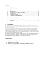
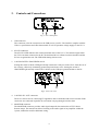
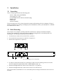
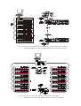
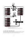
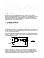
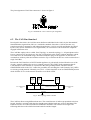
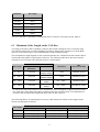
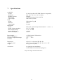
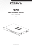
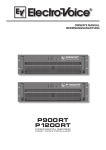
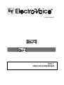
Owner’s Manual
UCC 1
USB-CAN CONVERTER
Contents
1.
2.
3.
3.1
3.2
4.
4.1
4.2
4.3
4.4
5.
6.
6.1
6.2
6.3
7.
1.
Description....................................................................................................................... 17
Controls and Connections................................................................................................ 18
Installation ....................................................................................................................... 19
Unpacking.................................................................................................................... 19
Rack-Mounting............................................................................................................ 19
Initial Operation............................................................................................................... 20
PC Connection and CAN Driver Installation .............................................................. 20
Installing IRIS.............................................................................................................. 20
CAN-Bus Connection.................................................................................................. 20
ISOLATED / GROUNDED Switch ............................................................................ 22
Monitor Bus..................................................................................................................... 23
Technical Information ..................................................................................................... 23
The UCC1 USB-CAN Converter ................................................................................ 23
The CAN-Bus Standard............................................................................................... 24
Maximum Cable Length on the CAN-Bus .................................................................. 25
Specifications................................................................................................................... 27
Description
The UCC1 USB-CAN CONVERTER is a bi-directional USB-to-CAN interface converter and is
therefore the perfect solution for interconnecting Electro-Voice appliances with serial CAN-busses and
PC or Notebook computers.
The UCC1 is a standalone unit with interface drivers for CAN and USB, audio monitoring output,
USB and CAN controllers as well as microphone controllers for converting commands and data
between PC and CAN-bus-units. The isolated CAN-bus interface reduces ground-loop interference
noise to an absolute minimum. The UCC1 receives its operational power via USB from the connected
PC, so that no external power supply unit is needed.
This owner’s manual illustrates installation and initial operation of the UCC1 when used together with
Electro-Voice P-Series Remote Amplifiers. Please, carefully read and mind all instructions and
precautions. Keep this owner’s manual at a save place for further reference.
Characteristics
•
•
•
•
•
Data rate up to 500 kbit/s
Galvanic separation of the CAN-bus, switchable
100 network devices possible
Monitor-bus in network cabling; output signal via XLR-type connector
Power supply via USB from the connected PC; separate power supply unit is not
needed
17
2.
Controls and Connections
Fig. 1: UCC1 front panel
1. USB connector
This connector is for the connection to the USB-port on your PC. The interface complies with the
USB 1.1 specifications and offers data transfer as well as operation voltage supply for the UCC1.
2. STATUS indicator
The STATUS LED indicates the actual operational state of the UCC1. The indicator lights when
the UCC1 has been connected to the PC, the dedicated driver software has been installed, and the
PC has recognized the unit. The LED blinks during data accesses.
3. CAN ISOLATED / GROUNDED switch
Setting this switch to ISOLATED galvanically isolates the CAN-port of the UCC1 from the rest of
the circuitry, effectively eliminating ground-loop interference noise. Setting the switch to
GROUNDED galvanically connects the CAN-bus to the USB-port ground and thus to the PC.
Fig 2: UCC1 rear view
4. CAN BUS IN / OUT connectors
These two sockets are for connecting EV-appliances that are furnished with serial CAN-bus. Both
connectors are connected in parallel for convenient carrying through CAN-bus data.
5. MONITOR connector
The MONITOR connector provides audio signal output for the monitor bus of EV P-Series
Remote Amps. The monitor bus allows listening to the audio signal of any amplifier within the
system, without the need for additional wiring.
18
3.
Installation
3.1 Unpacking
The UCC1 package includes the following parts:
1 UCC1 USB-CAN CONVERTER
1 Front panel 19“, 1HU
2 CAN-TERM 120 Ω CAN-bus terminator-plug
4 Rubber feet
1 USB cable
1 Owner’s manual
Upon receiving your UCC1, please inspect the contents of the package for loss or damage. If any of
the here listed parts are missing or damaged, please immediately contact your distributor or a TELEX /
EVI Audio service center.
3.2 Rack-Mounting
The compact UCC1 adapter is mainly aimed for connection to a laptop or notebook computer.
However, the supplied 19“ front panel allows trouble-free integration in a rack shelf system. For
mounting the 19“ front panel, please proceed as follows:
1. Loosen the two center screws on the UCC1’s panel (1).
2. Loosen the four corner screws on the UCC1’s panel (2).
3. Remove the original UCC1 panel (3).
Fig. 3: Exchanging UCC1 front panels
4. Fix the 19“ front panel on the UCC1. In doing so, make sure not to damage, bend or stress the
STATUS indicator and the ISOLATED / GROUNDED switch. (4).
5. Reinsert and tighten the two center screws of the UCC1 19“ panel (5).
6. Reinsert and tighten the four corner screws of the UCC1 enclosure (6).
Now you are able to install the UCC1 in a rack shelf system securing it with the four rack-screws on
the sides.
19
4.
Initial Operation
Follow these four steps when operating the UCC1 for the first time: Connect the UCC1 to the PC and
install the CAN drivers, install the IRIS-software, connect the desired appliances to the CAN-bus, and
set the ISOLATED / GROUNDED switch accordingly.
4.1 PC Connection and CAN Driver Installation
Use the supplied USB cable for connecting the UCC1 to your PC’s or Notebook’s USB-socket. The
computer system normally recognizes the UCC1 at once and the operating system asks for the
corresponding driver software. This files are stored in the root directory of the IRIS CD.
Insert the IRIS CD in your CD-drive and select the corresponding drive in the installation dialog. The
operating system will find all necessary driver files there. For correct installation follow the
instructions on your computer screen. For further information please check the IRIS Readme-File,
also.
The UCC1 is ready for operation as soon as the STATUS LED lights.
4.2 Installing IRIS
Next, you have to install the IRIS – Intelligent Remote & Integrated Supervision – software package
on your PC or Notebook computer. Detailed explanation is provided in the accompanying IRIS
Readme-File. Just follow the instructions in the installation dialog.
The STATUS LED blinks whenever the IRIS program is started and accesses the UCC1, indicating
that USB-port data communication has been activated.
4.3 CAN-Bus Connection
The CAN-bus is a serial interface for transferring commands and data. Since the CAN-bus is based on
serial bus architecture, all participating appliances have to be connected in series, i.e. cables have to
run from each participant on the bus system to the next. Whether a connected appliance is an amplifier
or the UCC1 USB-CAN Converter is generally of no further importance, which allows the integration
of the UCC1 – and therefore the PC – at any point on the CAN-bus. Including several UCC1s and PCs
on a single CAN-bus is possible as well.
Each participant on the bus system has two RJ-45 connectors for the Remote CAN-bus. These sockets
are connected in parallel to serve as input and output for carrying through the data information of the
remote-network. The CAN-port follows balanced design, which makes the use of Twisted-Pair cables
absolutely mandatory.
Both ends of the CAN-bus have to be terminated with 120 Ω. Two CAN-TERM 120 Ω termination
plugs are supplied with the UCC1. Connect one of these each to the RJ-45 connector that is not in use
of the first and the last appliance on CAN-bus.
The following diagrams are examples of the system cabling for different order of size configurations:
20
Fig 4:
System set-up with 5 amps and a single UCC1 / PC being the first unit on the bus
Terminators at the UCC1 (first unit) and at the amp No.5 (last unit on the bus)
Fig 5:
System set-up with 2 racks and a single UCC1 / PC in the middle
Terminators at amp No. 6 (first unit) and amp No. 12 (last unit on the bus)
21
Fig 6:
System with several racks and several UCC1 / PCs
UCC1 anywhere on the CAN-bus
Terminators at amp No. 10 (first unit) and amp No. 16 (last unit on the bus)
4.4 ISOLATED / GROUNDED Switch
Principally, the CAN-bus is galvanically isolated from any other participant on the bus, i.e. from all PSeries Remote amps and from the UCC1 USB-CAN Converter as well, a circumstance which as a
matter of fact results in effective elimination of ground-loop interference noise.
22
The ISOLATED / GROUNDED switch located on the UCC1’s front panel allows bridging this
galvanic isolation putting the CAN-bus of the UCC1 on circuitry ground potential.
The CAN-bus should normally be referenced to the ground potential at one single point in the
network. Set the switch to its GROUNDED-position when only one UCC1 is used in a single CANbus network. When employing several UCC1s in a CAN-bus network, setting the ISOLATED /
GROUNDED switch of one UCC1 to GROUNDED while leaving the switches of all other UCC1s in
the ISOLATED-position is recommended.
5.
Monitor Bus
Next to the CAN-bus signal, network cabling also holds the balanced audio-monitor signal for
monitoring the power amp inputs and outputs. This monitor-bus allows software-controlled
monitoring of the input and output signals of all power amps that are included in the remote network,
without the need for additional wiring. The monitor signal is present at the UCC1’s XLR-type
MONITOR Output connector for further distribution to (e.g.) a mixing console to be monitored via
headphones or an active monitor speaker connected.
6.
Technical Information
6.1 The UCC1 USB-CAN Converter
The UCC1 is an USB-to-CAN adapter, which offers the possibility to easily include any PC or
Notebook computer that is equipped with an USB-port in an existing CAN-network. The USB driver,
which is part of the IRIS-software is the only thing needed for triggering. The UCC1 gets its power
supply from the PC’s USB-port, so that no external power supply unit is necessary.
The following block diagram shows the UCC1’s internal structure with USB-port and controller on the
one side and the CAN-bus interface with CAN-transceiver component and galvanic separation on the
other side. The controller is responsible for the data format conversion between USB-port and CANbus, allowing data rates of up to 500 kbit/s.
Next to the CAN-bus, the network cabling also holds the monitor bus, which serves for monitoring the
input or output audio signals of all amplifiers that are included in the network. This audio signal is
present at the UCC1’s XLR-type MONITOR Output connector to provide trouble-free connection to a
mixer input or an additional amplifier.
IN
CAN BUS
OUT
USB & CAN
CONTROLLER
USB
ISOLATION
DATA
CAN
TRANSCEIVER
CAN Bus
Monitor Bus
CAN
GND
ISOLATED
GROUNDED
2
CAN
GND
1
3
USB
GND
MONITOR
Fig. 7: UCC1 Block Diagram
The CAN-bus port of the UCC1 (CAN BUS IN / OUT) is carried out via two Neutrik EtherCon
connectors to ensure most secure and reliably safe RJ-45 connections even under most wearing
conditions. The EtherCon connector series has been specially designed for use in ProAudio and OnStage applications. Matching Neutrik plug-type – NE8MC – connectors are also available.
23
The pin-assignment of CAN-bus connectors is shown in figure 8.
Fig. 8: CAN BUS IN / OUT connector pin-assignment
6.2 The CAN-Bus Standard
Developed in the 1980’s, the CAN-bus norm had been established in the 1990’s by the International
Standardization Organization (ISO) as a worldwide standard. Since then, CAN has become very
popular especially in automotive and industrial applications. CAN is cared for and further developed
by the CiA (CAN in Automation User Organization), an association of 300 well-known companies
engaged in different areas.
The CAN-Bus employs the so-called „Bus-Topology“ as network topology; i.e. all participants on the
bus are connected via one single two-wire line (Twisted-Pair-cable, with or without shielding), which,
at its ends has to be terminated using 120 Ω bus termination plugs. Each appliance on the bus can
communicate with any other unit without restriction. Up to 100 network devices can be connected on a
single CAN-Bus.
Because the CAN-interfaces of all EVI Audio appliances is galvanically isolated from the rest of the
circuitry, network cabling also carries a common ground (CAN_GND), which guarantees that all
CAN-interfaces in the network are connected to the same ground potential. The ISOLATED /
GROUNDED switch in the UCC1 offers the possibility for switching the CAN-Ground (CAN_GND)
to circuitry ground potential. Normally, one UCC1’s switch should be set to its GROUNDED-position
while all other UCC1s in the network should be set to ISOLATED.
CAN
DEVICE
1
CAN
DEVICE
2
CAN
DEVICE
n
CAN_H
BUS TERMINATION
120 Ω
CAN BUS UP TO 1000 m
BUS TERMINATION
120 Ω
CAN_L
CAN_GND
Fig. 9: Bus-topology of the CAN-bus
The CAN-bus allows using different data rates. The actual data rate is indirect proportional to the bus
length. “Smaller” networks with short bus lengths permit higher baud rates of up to 500 kbaud. The
baud rate needs to be reduced (minimum 10 kbaud) in networks with extensive bus length. The
following table shows the relation between baud rate and bus length:
24
Baud Rate
Bus Length
500 kbit/s
100 m
250 kbit/s
250 m
125 kbit/s
500 m
62,5 kbit/s
1000 m
20 kbit/s
2500 m
10 kbit/s
5000 m
The use of repeaters is generally recommended when a network’s bus length exceeds 1000 m.
6.3 Maximum Cable Length on the CAN-Bus
According to the ISO 11898-2 standard, CAN-bus data transfer cabling has to be carried out using
Twisted-Pair cables with or without shielding providing a characteristic impedance of 120 Ω. Both
ends of a CAN-network have to be terminated with 120 Ω termination plugs.
The maximum bus length depends on the actual data transfer rate, which kind of data transfer cable is
used and the total number of participants on the bus. The following table shows the most essential
coherencies for CAN-networks consisting of up to 64 participants:
Bus Length
*
Data Transfer Cable
Length-Related
Resistance
Cable Diameter
Termination
Max.
Data Transfer Rate
0 ... 40 m
< 70 mΩ/m
0,25 ... 0,34 mm2
AWG23, AWG22
124 Ω
1000 kbit/s for 40 m
40 ... 300 m
< 60 mΩ/m
0,34 ... 0,6 mm2
AWG22, AWG20
127 Ω
500 kbit/s for 100 m
300 ... 600 m
< 40 mΩ/m
0, 5 ... 0,6 mm2
AWG20
150 ... 300 Ω
*
100 kbit/s for 500 m
600 ... 1000 m
< 26 mΩ/m
0,75 ... 0,8 mm2
AWG18
150 ... 300 Ω
*
62,5 kbit/s for 1000 m
To reduce the load for the interface driver and therefore also reducing the voltage drop between the
two cable ends, using higher impedance termination than the specified 120 Ω is recommended for
networks with increased cable length and many nodes on the CAN-bus.
The following table is for estimating the necessary cable diameter in relation to the length and the
amount of participants on the bus:
Number of Units on the CAN-bus
Bus Length
32
64
2
2
100
2
100 m
0,25 mm respectively AWG24 0,34 mm respectively AWG22 0,34 mm respectively AWG22
250 m
0,34 mm2 respectively AWG22
0,5 mm2 respectively AWG20
0,5 mm2 respectively AWG20
500 m
0,75 mm2 respectively AWG18 0,75 mm2 respectively AWG18
1,0 mm2 respectively AWG17
25
Additionally, the length of any stub lines for participants that are not directly connected to the CANbus needs to be kept in mind. For data transfer rates of up to 125 kbit/s the length of a single stub cable
should not exceed 2 m. For higher bit rates a length of max. 0.3 m has not to be exceeded. The entire
length of all stub lines should not exceed 30 m.
General note:
Using commercial quality RJ-45 patch cables with a characteristic impedance of 100 Ω (AWG
24 / AWG 26) for rack cabling is generally possible for short distances of up to 10 m.
For the interconnection of rack shelf systems as well as in fixed installations obeying the
guidelines for network cabling, as mentioned above, is mandatory.
26
7.
Specifications
CAN BUS:
Sockets
Baud Rate
Number of Nodes
Data Format
Cable Length
USB:
Socket
Standard
Cable Length
MONITOR:
Socket
Output Voltage (nominal)
Max. Output Voltage
Output Impedance
Min. Load Impedance
2 x RJ-45 parallel (NEUTRIK EtherCon compatible)
500 / 250 / 125 / 62,5 / 20 / 10 kbit/s
100 max.
CAN specification 2.0B (29 bit ID)
1000 m at 62,5 kbit/s
USB socket, Type B
USB 1.1
3m max.
XLR male, electronically balanced (Pin 2 = +, Pin 3 = -)
1.55 V / +6 dBu
8.7 V / +21 dBu
< 100 Ω
600 Ω
Power Supply
Power Consumption
Operation Temperature Range
Certified
+ 5 V DC (from USB interface)
200 mA max.
0 °C … 50 °C
CE
Dimensions
with 19“ panel
Weight
105 x 39.5 x 130.4 mm (W x H x D)
483 x 43.6 x 130.4 mm (W x H x D), 19“ / 1 HU
0.8 kg (with 19“ panel)
Accessories
19“ panel for rack installation
CAN-TERM 120 Ω termination plug (2x)
- subject to changes without further notice -
27