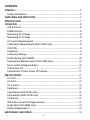
1
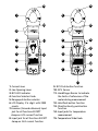
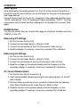
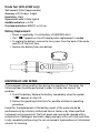
ACD-20SW/ACD-21SW Digital Clamp Meter Users Manual • • • • Mode d’emploi Bedienungshandbuch Manual d’Uso Manual de uso Digital Clamp Meter Users Manual July 2009, Rev.1 ©2009 Amprobe Test Tools. All rights reserved. Printed in Taiwan English ACD-20SW/ACD-21SW Limited Warranty and Limitation of Liability Your Amprobe product will be free from defects in material and workmanship for 1 year from the date of purchase. This warranty does not cover fuses, disposable batteries or damage from accident, neglect, misuse, alteration, contamination, or abnormal conditions of operation or handling. Resellers are not authorized to extend any other warranty on Amprobe’s behalf. To obtain service during the warranty period, return the product with proof of purchase to an authorized Amprobe Test Tools Service Center or to an Amprobe dealer or distributor. See Repair Section for details. THIS WARRANTY IS YOUR ONLY REMEDY. ALL OTHER WARRANTIES - WHETHER EXPRESS, IMPLIED OR STAUTORY - INCLUDING IMPLIED WARRANTIES OF FITNESS FOR A PARTICULAR PURPOSE OR MERCHANTABILITY, ARE HEREBY DISCLAIMED. MANUFACTURER SHALL NOT BE LIABLE FOR ANY SPECIAL, INDIRECT, INCIDENTAL OR CONSEQUENTIAL DAMAGES OR LOSSES, ARISING FROM ANY CAUSE OR THEORY. Since some states or countries do not allow the exclusion or limitation of an implied warranty or of incidental or consequential damages, this limitation of liability may not apply to you. Repair All test tools returned for warranty or non-warranty repair or for calibration should be accompanied by the following: your name, company’s name, address, telephone number, and proof of purchase. Additionally, please include a brief description of the problem or the service requested and include the test leads with the meter. Non-warranty repair or replacement charges should be remitted in the form of a check, a money order, credit card with expiration date, or a purchase order made payable to Amprobe® Test Tools. In-Warranty Repairs and Replacement – All Countries Please read the warranty statement and check your battery before requesting repair. During the warranty period any defective test tool can be returned to your Amprobe® Test Tools distributor for an exchange for the same or like product. Please check the “Where to Buy” section on www.amprobe.com for a list of distributors near you. Additionally, in the United States and Canada In-Warranty repair and replacement units can also be sent to a Amprobe® Test Tools Service Center (see next page for address). Non-Warranty Repairs and Replacement – US and Canada Non-warranty repairs in the United States and Canada should be sent to a Amprobe® Test Tools Service Center. Call Amprobe® Test Tools or inquire at your point of purchase for current repair and replacement rates. In USA In Canada Amprobe Test Tools Amprobe Test Tools Everett, WA 98203 Mississauga, ON L4Z 1X9 Tel: 888-993-5853 Tel: 905-890-7600 Fax: 425-446-6390 Fax: 905-890-6866 Non-Warranty Repairs and Replacement – Europe European non-warranty units can be replaced by your Amprobe® Test Tools distributor for a nominal charge. Please check the “Where to Buy” section on www.amprobe.com for a list of distributors near you. Amprobe® Test Tools Europe In den Engematten 14 79286 Glottertal, Germany tel: +49 (0) 7684 8009 - 0 *(Correspondence only – no repair or replacement available from this address. European customers please contact your distributor.) 14 10 1 1 11 2 3 2 12 4 5 11 9 3 12 4 13 5 9 6 6 7 7 8 14 8 15 1. Current Jaws 2. Jaw Opening Lever 3. NCV LED indicator 4. Function Selector Knob 5. Range push button selector 6. LCD Display 3 ¾ digit with 3999 counts 7.Common (Ground reference) Input jack for all functions EXCEPT clamp-on ACA current function 8. Input jack for all functions EXCEPT clamp-on ACA current function 9. NCV Push button function 10. NCV Sensor 11. Hand/Finger Barrier to indicate the limits of safe access of the meter during measurement 12. Hold Push button function 13. Ohm/Continuity push button function 14. Input jacks for temperature measurement 15. Temperature Slide Knob CONTENTS SYMBOLS.............................................................................................................5 Safety Information.........................................................................................5 UNPACKING AND INSPECTION...........................................................................7 INTRODUCTION...................................................................................................7 OPERATION..........................................................................................................8 HOLD Button...................................................................................................8 RANGE Button................................................................................................8 Measuring DC Voltage...................................................................................8 Measuring AC Voltage...................................................................................8 AC Current Measurement..............................................................................8 Capacitance Measurement (ACD-21SW only)...............................................9 CAUTION.........................................................................................................9 Resistance........................................................................................................9 Continuity Testing...........................................................................................9 Diode Testing (ACD-20SW)...........................................................................10 Temperature Measurement (ACD-21SW only)............................................10 Non-Contact Voltage Indicator....................................................................10 Auto Power off.............................................................................................11 Cancellation of Auto Power off feature:....................................................11 SPECIFICATIONS ...............................................................................................11 DC Volts.........................................................................................................12 AC Volts.........................................................................................................12 AC Current....................................................................................................12 Resistance......................................................................................................12 Capacitance (ACD-21SW only).....................................................................13 Temperature (ACD-21SW only)....................................................................13 Continuity.....................................................................................................13 (NCV) Non-Contact Voltage Indicator.........................................................13 Diode Test (ACD-20SW only)........................................................................14 Battery Replacement....................................................................................14 MAINTENACE AND REPAIR...............................................................................14 1 SYMBOLS Battery W Refer to the manual T Double Insulated J Earth Ground B Alternating Current F Direct Current P Complies with EU directives , Application around and removal from hazardous live conductors is permitted ; Conform to relevant Australian standards = Do not dispose of this product as unsorted municipal waste m Audible tone ) I Fuse Canadian Standards Association (NRTL/C) Safety Information • The ACD-20SW and ACD-21SW swivel Clamp meters conform to EN610101:2001; EN61010- 2-032:2002; CAT III 600 V, class II; pollution deg.2 and EN61326-1 (EMC compliance) • This instrument is EN61010-1 certified for Installation Category III (600V). It is recommended for use in primary supply lines, overhead lines and cable systems and distribution level and fixed installations, as well as lesser installations. • Do not exceed the maximum overload limits per function (see specifications) nor the limits marked on the instrument itself. Never apply more than 600 V ac rms between the test lead and earth ground. WWarnings and Precautions • Before and after hazardous voltage measurements, test the voltage function on a known source such as line voltage to determine proper meter functioning. • Disconnect the test leads from the test points before changing meter functions. • Disconnected from the meter’s test leads before measuring current. 2 • Inspect the Clamp meter, test leads and accessories before every use. Do not use any damaged part. • Never ground yourself when taking measurements. Do not touch exposed circuit elements or test probe tips. • Do not operate the instrument in an explosive atmosphere. • To reduce the risk of fire or electric shock, do not expose this product to rain or moisture. • The meter is intended only for indoor use. To avoid electrical shock hazard, observe the proper safety precautions when working with voltages above 60 VDC, 42.4 Vpk, or 30 VAC rms. These voltage levels pose a potential shock hazard to the user. • Before and after hazardous voltage measurements, test the voltage function on a known source such as line voltage to determine proper meter functioning. • Keep your hands/fingers behind the hand/finger barriers (of the meter and the test leads) that indicate the limits of safe access of the hand-held part during measurement. • Inspect test leads, connectors, and probes for damaged insulation or exposed metal before using the instrument. If any defects are found, replace them immediately. • This Clamp-on meter is designed to apply around or remove from uninsulated hazardous live conductors. Individual protective equipment must be used if hazardous live parts of the installation could be accessible. • Exercise extreme caution when: measuring voltage >20 V // current >10 mA // AC power line with inductive loads // AC power line during electrical storms // current, when the fuse blows in a circuit with open circuit voltage >600 V // servicing CRT equipment. • Remove test leads before opening the case to change the battery. • Disconnect circuit power and discharge all high-voltage capacitors before testing resistance, continuity, diodes, or capacitance. • To avoid false readings, which could lead to possible electric shock or personal injury, replace the batteries as soon as the low battery indicator ( ) appears. • To avoid electric shock hazard, do not use the HOLD mode to determine if a circuit is live. Unstable readings will not be captured and displayed. WCAUTION For non-invasive ACA current measurements, clamp the jaws around only one single conductor of a circuit for load current measurement. More than 1 conductor will cause false readings 3 UNPACKING AND INSPECTION Your shipping carton should include: 1 ACD-20SW or ACD-21SW Swivel Clamp Meter 1 Set of Test leads 1 Soft Carrying Case 1 Users Manual 1 Type K Thermocouple probe (Model ACD-21SW only) 2 1.5V AAA Batteries (Installed) If any of the items are damaged or missing, return the complete package to the place of purchase for an exchange. Introduction The ACD-20SW and ACD-21SW clamp-On meters come with a new patented rotating head design that allows easy viewing of the measurements in tight or inconvenient to reach places. Simply rotate the body of the meter to get an unobstructed view of the LCD display. Rich set of features and CAT III 600V safety reading for use in electrical and HVAC applications. The features include: • 180 degree rotating head for the perfect display viewing • Advanced VoltTect non-contact voltage detection • Slim jaw design with one hand operation • Measures AC Current up to 400 ACA, AC/DC Voltage up to 600V, • Resistance and Capacitance(ACD-21SW only) • Temperature measurement (ACD-21SW only) • Audible continuity • Auto and manual ranging respectively for quick checks and precise measurements • Auto power off • Data hold • Diode Test (ACD-20SW only) • Accommodates conductors up to 1.18” (30mm) in diameter 4 OPERATION HOLD Button Data hold freezes the reading present on the LCD at the moment the button is pressed.To use this menu feature, set up the meter for the type of measurement and range desired. Connect the test leads to the circuit / component to be measured and then press “HOLD” push button. The LCD reading will freeze and display “HOLD.” You may now remove the test leads and the reading will not change until you press Hold again. RANGE Button This function allows the user to select the range of a function that does not show ‘RANGE’ on the LCD. Measuring DC Voltage 1.Set the Function Switch to L 2.Connect the test leads: Red to +, Black to COM. 3.Connect the test probes to the circuit test points. Refer to Fig.1 4.Read the display. If necessary, correct any overload ( 0L) conditions. Measuring AC Voltage 1.Set the Function Switch to K. 2.Connect the test leads: Red to +, Black to COM. 3.Connect the test probes to the circuit test points. Refer to Fig.2 4.Read the voltage on the primary display and the frequency on the secondary display. If necessary, correct any overload (0L) conditions. AC Current Measurement 1.Set the Function Switch to position ?. 2.Open spring-loaded clamp by pressing the jaw opening lever on the left side of meter. 3.Position clamp around one wire or conductor. Release the jaw opening lever. Wire should be center inside the jaws. Refer to Fig.3 4.Read the current on the primary display and the frequency on the secondary display. If necessary, correct any overload (OL) conditions. 5 Capacitance Measurement (ACD-21SW only) When testing a capacitor that is part of a circuit, if “dS.C” is displayed on the screen, a voltage is present. Discharge the capacitor before testing. 1.Sett the Function Switch to “ E ” position. 2.Connect the test leads: Red to +, Black to COM. 3.Connect the test probes to the circuit test points. Refer to Fig. 4 4.Read the display. If necessary, correct any overload (0L) conditions. WCAUTION Using the Resistance or Continuity function in a live circuit will produce false results and may damage the instrument. In most cases the suspected component must be disconnected from the circuit to obtain an accurate reading. Resistance 1.Set the Function Switch to e. Use the “e/R“ button to select the resistance test (ACD-21SW only). 2.Connect the test leads: Red to +, Black to COM. 3.Turn off power to the circuit being measured. Never measure resistance across a voltage source or on a powered circuit. 4.Discharge any capacitors that may influence the reading. 5.Connect the test probes across the resistance. Refer to Fig.5 6.Read the display. If 0L appears on the highest Range, the resistance is too large to be measured or the circuit is an open circuit. Continuity Testing 1.Set the Function Switch to . Use the “e/R“ button to select the test (ACD-21SW only). 2.Connect the test leads: Red to +, Black to COM. 3.Turn off power to the circuit being measured. 4.Discharge any capacitors that may influence the reading. 5.Connect the test probes across the resistance or the two points of test 6.Listen for the tone that indicates continuity (< 25e). 6 Diode Testing (ACD-20SW) 1.Set the Function Swith to “ “ position. 2.Connect the red test lead to the “Ve” jack and the black test lead to the “COM” jack. 3.Turn off power to the circuit under test. External voltage across the components may cause invalid readings. 4.Connect the probes to the diode. A forward-voltage drop is about 0.6V (typical for a silicon diode). 5.Reverse probes connection with the diode. If the diode is good, “OL” isdisplayed. If the diode is shorted, “0.00” or another number is displayed. 6.If the diode is open, “OL” is displayed in both directions. 7.Audible Indication: Less than 0.25V. Temperature Measurement (ACD-21SW only) 1.Verify that the location being tested is not electrically energized. 2.Set the Function Switch to 400°F position. 3.Move the slide knob to the TEMP position. Insert the thermocouple plug matching the slot widths. 4.Connect the thermocouple bead to the test point. Refer to Fig.6 5.Read the display. If 0L appears on the display, the temperature is too large to be measured or the thermocouple is open. 6.Setting up for 400°C or 400°F measurements: Open bottom case, and find the jumper (next to jack) on (400°C) when the jumper is short, and reads in degree Fahrenheit (400°F) when the jumper is open. Note:The test leads must be removed to move the slide plate to allow the thermocouple to be inserted. Non-Contact Voltage Indicator 1.Remove the test leads from the meter. Push the “NCV” button at any selected function/Range. Then the display will be shut down and LED flashes with a short “chirp” sound for self-test. Refer to Fig. 7 2.With the NCV tab on the tip of the clamp close to an AC voltage, Press the “NCV” button, the NCV LED will light and the beeper will beep. The closer you get to AC voltage, the louder the beep. 7 Auto Power off 1.Auto power off: approx. 10 minutes. 2.After auto power off, press any button to restart the meter, and the reading of measurement will be maintained in the display. Cancellation of Auto Power off feature: • Press and hold the (RANGE) button while rotating function switch from off to any position to turn the meter on. • The auto power off feature is disabled. • Note “APO” annunciator is missing from the LCD. SPECIFICATIONS Display: 3¾ digit liquid crystal display (LCD) with a maximum reading of 3999. Polarity: Automatic, positive implied, negative polarity indication. Over range: (OL) or (-OL) is displayed. Zero: Automatic. Low battery indication: The “ ” is displayed when the battery voltage drops below the operating level. Measurement rate: 2 times per second, nominal. Auto power off: Approx. 10 minutes. Operating environment: 0°C to 50°C(32°F to 122°F) at < 70% relative humidity. Storage temperature: -20°C to 60°C(-4°F to 140°F) at < 80% relative humidity. Accuracy: Stated accuracy at 23°C±5°C, <75% relative humidity. Temperature Coefficient: 0.1 × (specified accuracy) per °C. (0°C to 18°C, 28°C to 50°C). Altitude: 6561.7 Feet (2000m). Jaw opening capability: 30mm conductor. Power: 1.5 volt battery x2, R03/SIZE AAA. Battery life:75 hours typical with carbon-zinc (ACD-21SW). 75 hours typical with carbon-zinc (ACD-20SW). Dimensions: 240 × 70 × 41 mm (9.5 x 2.8 x 16 IN). Weight: Approx. 7.7 oz. (220g). 8 DC Volts Ranges Resolution Accuracy 400mV, 4V, 40V, 400V, 600V 0.1mV ±(0.5% rdg + 2 dgts) Input impedance: 400mV: >100Me; 4V: 10Me; 40V ~ 600V: 9.1Me Overload protection: 600VDC or AC rms AC Volts (50Hz - 500Hz) Ranges Resolution Accuracy 4V, 40V, 400V 1mV ±(1.2% rdg + 5 dgts) on 4V to 400V ranges 600V 1mV ±(1.5% rdg + 5 dgts) on 600V range Input impedance: 4V: 10Me; 40V ~ 600V: 9.1Me Overload protection: 600VDC or AC rms AC Current (50Hz - 60Hz) Ranges Resolution Accuracy 40A, 400A 0.01A ±(2.0% rdg + 6 dgts) Overload protection: 400AAC Resistance Ranges Resolution Accuracy 400e, 4ke, 40ke, 400ke 0.1e ±(1.0% rdg + 4 dgts) 4Me 0.1e ±(1.5% rdg + 4 dgts) 40Me 0.1e ±(3.0% rdg + 5 dgts) Open circuit volts: -0.45V dc typical, (-1.2Vdc on 400e range) Overload protection: 600VDC or AC rms 9 Capacitance (ACD-21SW only) Ranges Resolution Accuracy 4μF 1nF ±(3.0% rdg + 15 dgts) 40μF, 400μF 1nF ±(3.0% rdg + 5 dgts) 4mF 1nF ±(5.0% rdg + 20 dgts) Minimum input range: >100nF 4nF, 40nF, 400nF ranges unspecified When the capacitor to be tested is connected, if “dS.C” symbol indicates on LCD, it means there is voltage existing in the tested capacitor and need to be discharged before testing. Overload protection: 600VDC or AC rms Temperature (ACD-21SW only) Range -35°C ~ 400°C, -30°F ~ 400°F, Resolution 0.1°F, 0.1°C Accuracy ±(1.0% + 2°F) 32°F ~ 400°F ±(1.0% + 1°C) 0°C ~ 400°C ±(2.0% + 6°F) -30°F ~ 32°F ±(2.0% + 3°C) -35°C ~ 0°C Sensor type: K-type thermocouple Overload protection: 30V Max Continuity Range: 400e Resolution: 1e Audible indication: Less than 25e Response time: 500ms Overload protection: 600VDC or AC rms (NCV) Non-Contact Voltage Indicator Detect voltage from 70V to 600VAC (50Hz ~ 60Hz) Red LED and audible indicator 10 Diode Test (ACD-20SW only) Test current: 0.8mA (approximate) Accuracy: ±(3.0% rdg + 3 dgts) Resolution: 10mV Open circuit volts: 3.0Vdc typical Audible indication: < 0.25V Overload protection: 600VDC or AC rms Battery Replacement • Power is supplied by 1.5 volt battery x2 (LR03/SIZE AAA ). • The “ “ appears on the LCD display when replacement is needed. • To replace the battery, remove the two screws from the back of the meter and lift off the front case. • Remove the battery from case bottom. MAINTENACE AND REPAIR If there appears to be a malfunction during the operation of the meter, the following steps should be performed in order to isolate the cause of the problem. 1.Check the battery. Replace the battery immediately when the symbol “ ” appears on the LCD. 2.Review the operating instructions for possible mistakes in operating procedure. Except for the replacement of the battery, repair of the meter should be performed only by a Factory Authorized Service Center or by other qualified instrument service personnel. The front panel and case can be cleaned with a mild solution of detergent and water. Apply sparingly with a soft cloth and allow to dry completely before using. Do not use aromatic hydrocarbons or chlorinated solvents for cleaning. 11 ACD-20SW Fig.1 Measuring DC Voltage Fig.3 Measuring AC Current 12 Fig.2 Measuring AC Voltage Fig.4 Measuring Capacitance Fig.5 Fig.7 Measuring Resistance Fig.6 OFF ON OFF OFF ON OFF OFF ON OFF OFF ON OFF OFF ON OFF OFF ON OFF Non-Contact voltage (NCV) Measurement 13 Measuring Temperature 14