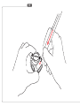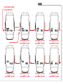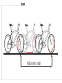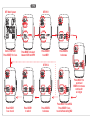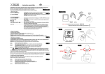
1
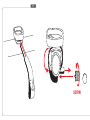
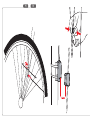
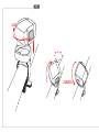
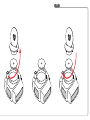
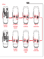
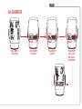
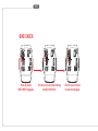
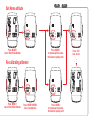
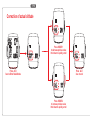
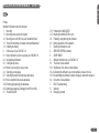
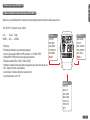
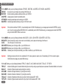
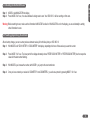
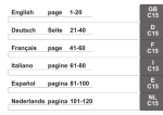
CYCLECOMPUTING
INSTRUCTION MANUAL
BEDIENUNGSANLEITUNG
MANUEL D´INSTALLATION ET D´UTILISATION
MANUALE D´INSTALLAZIONE E FUNZIONAMENTO
INSTALACION Y OPERACIÓN MANUAL
HANDLEIDING
MC1.0
P1
screw
P1
P2
P4
LOCK
UNLOCK
2.UNLOCK
P5
P6
P7
Press AC-Button to Begin
or install battery (P6)
automatic
•••••••
Press MODE 2 for next
press MODE 1 to select
Press MODE 2 for next
press MODE 1 to select
Press MODE 2 for next
press MODE 1 to select
Press MODE 2 for next
press MODE 1 to select
Press MODE 2 for next
press MODE 1 to select
Press MODE 2 for next
press MODE 1 to select
Press MODE 2 for next
press MODE 1 to select
P8
1x
WS in mm / inch
P9
ETRTO
47-305
47-406
34-540
47-507
23-571
40-559
44-559
47-559
50-559
54-559
57-559
37-590
20-571
16x1,75
20x1,75
24x1 3/8
24x1,75
26x1
26x1,5
26x1,6
26x1,75
26x1,9
26x2,00
26x2,125
26x1 3/8
26x3/4
WS in mm KMH
WS in inch MPH
1272
1590
1948
1907
1973
2026
2051
2070
2089
2114
2133
2105
1954
50,1
62,6
76,7
75,1
77,7
79,8
80,7
81,5
82,2
83,2
84,0
82,9
76,9
ETRTO
32-630
40-622
47-622
40-635
37-622
18-622
20-622
23-622
25-622
28-622
32-622
37-622
40-622
27x1 1/4
28x1,5
28x1,75
28x1 1/2
28x1 3/8
700x18C
700x20C
700x23C
700x25C
700x28C
700x32C
700x37C
700x40C
WS in mm KMH
WS in inch MPH
2199
2224
2268
2265
2205
2102
2114
2133
2146
2149
2174
2205
2224
86,6
87,6
89,3
89,2
86,8
82,8
83,2
84,0
84,5
84,6
85,6
86,8
87,6
P10
SET Metric System
SET WS 1
Start at TRIP DIST
Press MODE 1 for 3 sec.
Press MODE 2 to select
between KMH and MPH
Press MODE 1
to set WS1
Press MODE 2
to increase
••••••••••••••••
• • • • • • • • • • • • • • • • • • • • • • • • • • • • • • • • • • • • • • • • • • • • • • • • • • •• • • • • •
SET WS 2
•••••
Press MODE 1
3 sec. to end
Press MODE 1 to
switch and
MODE 2 to increase
continue for
all 4 digits
•••••
Press MODE 1
to switch
Press MODE 2
to increase
Press MODE 1 to set WS2
Press MODE 1 3 sec.
to end without setting WS2
P11
SET Clock
Press MODE 1
3sec.to start
Press MODE 2 to
switch between
24h or 12h
Press MODE 1
to set the hours
MODE 2 to
increase the hours
Press MODE 1
3 sec. to end
Press MODE 2
to increase the
minutes
Press MODE 1
to set the minutes
P12
P13
Set Navigator
•••••••
Press MODE 2
to increase
Reset Navigator
Press MODE 1
to switch
Press MODE1 3 sec. to end
after you set the navigator
••••••••••••••••••••••••••
Press MODE 1
3sec.to start
•••••••
Important:
Navigator in Display
Press MODE 2
to reset
P14
Set ODOMETER
Press MODE 1
3sec.to start
Press MODE 2
to increase
Press MODE 1
to switch
Press MODE1
3 sec. to end
after you set
the odometer
••••••••••
•••••••
P15
BIKE CHECK
Press any button
BIKE CHECK disappears
The service icon will remain flashing.
Another 50 km/35 mi.
Then the service interval
icon will also disappear
P16
Set Home altitude
P17
Press MODE 1
to decrease privious value
Hold down to quickly scroll
Press MODE 1
3sec.to Enter Home Altitude
••
Re-calibrating altimeter
Press MODE 1
3sec.to Enter Home Altitude
Press MODE1+MODE2
3sec. to recalibration
Press ALTI
3sec. to end
Press MODE 2
to increase privious value
Hold down to quickly scroll
P18
Correction of actual altitude
Press MODE 1
to decrease privious value
Hold down to quickly scroll
Press ALTI
3sec.to Enter Real Altitude
Press ALTI
3sec. to end
Press MODE 2
to increase privious value
Hold down to quickly scroll
INSTALLATION AND OPERATION MANUAL - VDO MC 1.0
GB
Index
Preface
Important information about the altimeter
1.
Mounting
1.1 Mounting cable sensor and magnet
1.2 Mounting wire and VDO “any-size” handlebar holder
1.3 Twist-Click mounting of computer onto handlebarholder
1.4 Installing the battery
2.
Initial set-up of your VDO MC 1.0
2.1 Basic information on how to operate your VDO MC 1.0
2.2 Interrogating information
2.3 Calling set-up mode
2.3.1 Button / key covering in set-up mode
2.4 Selecting your language
2.5 Selecting the wheel circumference (wheelsize)
2.5.1 How to determine the precise wheelsize
2.5.2 Entering (programming) the wheelsize
2.5.3 Switching wheelsizes (Changing from WS1 to WS2)
2.7 The NAVIGATOR
MC
1.0
2.7.1 Presetting the NAVIGATOR
2.7.2 Resetting the NAVIGATOR to zero
2.8 Presetting / programming the odometer
2.9 Manual operation of the stopwatch
3.
Resetting information to zero
4.
SERVICE INTERVAL indicator
5.
SLEEP MODE
6.
Altimeter information of your VDO MC 1.0
6.1 The home or basis altitude
6.1.1 Significance of the home or basis altitude
6.1.2 Calibrating the altimeter to your home altitude or basis of choice
6.1.3 Re-calibrating the altimeter to absorb changes in barometric pressure
6.2 Correction of actual altitude
7.
FAQ / Troubleshooting
8.
Warranty
10. Packaging contents
1
Preface
GB
MC
1.0
Thank you very much for buying a VDO MC 1.0 bicycle computer featuring an altimeter. The more familiar you get with this model, the more enjoyable your
trips are going to be.
Hence, our urgent request:
Please read thoroughly all the information provided in this manual. You are getting important and useful hints for operation to make you fully benefit from all the
technical features of your VDO MC 1.0.
We wish you enjoyable trips and rides on your bike with VDO
CYCLE PARTS GMBH
Important information about the altimeter
The altitude calculation works by measuring barometric pressure. Your VDO MC 1.0 converts the data of current barometric pressure into the respective altitude.
Depending on the barometric pressure (weather) different altitude readouts for the same location may be displayed. That these barometric changes do not
reflect in your altitude readout, your VDO MC 1.0 features an easy-to use barometric pressure re-calibration (see chapter 6.1.3)
Accurate calculation of altitude requires the precise determination of home or basis altitude.
To process barometric pressure data, there is a hole drilled into the bottom of the housing of your VDO MC 1.0.
This hole must never be clogged or taped over.
Please do check on its cleanliness regularly and free the hole carefully if needed.
You must never poke a pointed instrument into the hole.
2
1.Mounting
GB
1.1 Mounting cable sensor and magnet
MC
1.0
Important: mount the sensor first, then mount the wired handlebar holder as described under 1.2
Check the following while mounting:
a.
Distance between the sensor and magnet: 1 to 5 mm
b.
When mounting the sensor on a suspension fork, don’t forget to allow extra length for the cable. WATCH OUT: cable may tear
step 1: Loosely attach the sensor on the fork leg with cable ties (do not tighten yet).
step 2: Mount the magnet on a spoke. Adjust the magnet to the marking on the sensor (distance 1-5 mm).
step 3: When adjustment has been done finalise mounting by tightening cable ties and clamping magnet.
P1+P2
1.2 Mounting wire and VDO “any-size” handlebar holder
step 1: Run the cable up the fork, pass it around the brake cable from the already fixed sensor to the handlebar.
Use the enclosed cable ties or duct tape. Spiral the wire around the brake cable (this has proven to be the best solution).
step 2: position the holder on the handlebar.
step 3: feed the fixing clamp through the slot below the holder socket, pass the clamp around the handlebar and tighten it with a small screw driver.
Do not overtighten, the plastic screw might be damaged. Readjust the cable so that it will not be stretched during steering.
Finally tighten the zip ties holding the sensor.
P3
3
1.3 Twist-Click mounting of computer on to holder
GB
MC
1.0
The Twist-Click mounting has been exclusively developed for the new line of VDO CYTEC computers. The VDO MC 1.0 also features the Twist-Click-System.
The computerhead is put onto the handlebar and by a right turn of the computerhead (TWIST) fixed to the holder (CLICK).
P4
It is just as easy to remove the computerhead from the handlebar holder. Slightly push the computerhead down, twist it to the left, remove computerhead
from handlebar holder.
P5
Watch out: Please remove the computerhead from the handelbar holder when you intend not to use your bike for a longer period of time. (battery power)
1.4 Installing the 3V battery (type 2032) into the computer head
To save battery power, your VDO MC 1.0 comes with the battery not yet fitted. Prior to initial use the batteries will first have to be installed with the positve
pole on top.
Warning: Once the battery is installed your VDO MC 1.0 starts the set-up of display language (see also chapter 2.4 for details).
P6
If you find the computer is not functioning properly after the battery is changed, push the AC-button (Auto Clear) on the rear side of the computer to reset.
P7
4
2. Initial set-up of your VDO
VDO MC
MC 1.0
1.0
GB
2.1 Basic information on how to operate your VDO
VDO MC
MC 1.0
1.0
MC
1.0
Make sure you are familiar with the computers basic operating instructions before the initial set-up and use.
Your VDO MC 1.0 features 3 keys / buttons
Left ......
Center......Right
MODE1..... ALTI........ MODE2
The display
The following information is permanentely displayed:
• Current / actual speed in KMH or MPH accurate to +/- 0.5 KMH / MPH
• Symbol (MPH or KMH) for the measuring system selected,
• Wheelsize selected: Bike 1 (WS1) or Bike 2 (WS2)
• Symbols to compare actual speed and average speed (up-arrow, down-arrow, dot)
• ALTI - display of current / actual altitude
• Current grade / inclination climbed or descended in %
• Current temperature in °C or °F
Function
TRIP DIST
RIDE TIME
AVG SPEED
STOP WATCH
MAX SPEED
Function
NAVI GATOR
CLOCK
ODO 1 METER
ODO 2 METER
ODO TOTAL
MODE 1
MODE 2
Function
TRIP ALTI
MAX ALTI
AVG CLIMB
MAX CLIMB
TOTAL ALTI
TOP ELVTN
ALTI
5
2.2 Interrogating information
GB
MC
1.0
With the MODE1 button you call up following information: TRIP DIST - RIDE TIME - AVG SPEED - STOP WATCH - MAX SPEED
TRIP DIST
trip counter for your individual trip, counting to 999.99 km or mi
RIDE TIME
trip timer featuring automatic start/stop function up to 19:59:59 h
AVG SPEED average speed, accurate to two decimal points
STOP WATCH manually operated stop watch counting up to 19:59:59
MAX SPEED maximum speed achieved during a ride up to 199.5 km/h or mph
Important:
If the ride timer overflows 19:59:59 h, it is automatically reset to 00:00:00. Simultaneously, your average speed counter AVG SPEED is reset to
zero. If your trip counter overflows 999.99 KM or M, it is automatically reset to 000.00 Simultaneously, your average speed counter AVG SPEED
and your ride timer RIDE TIME are reset to zero.
With the MODE2 button you call up following information: NAVI GATOR - CLOCK - ODO1 METER - ODO2 METER - ODO TOTAL
NAVI GATOR Second, manual trip counter, can be reset to zero individually, can be preset and counting up from there on.
CLOCK
Time of the day in 12h or 24h mode
ODO 1 METER Odometer (sum of all trips) on Bike 1, up to 99.999 km or mi.
ODO 2 METER Odometer (sum of all trips) on Bike 2, up to 99.999 km or mi.
ODO TOTAL Odometer (sum of all trips on both bikes), sum of Bike 1 and Bike 2, up to 199.999 km or mi.
Important:
Switching conversions from mi to km at odometer 62.111 mi and up leads to a reset to zero of the odometer. (62.111 mi converts to approx
100.000 km but the display only holds 99.999 km max.)
With the ALTI button you call up following information: TRIP ALTI - MAX ALTI - AVG CLIMB - MAX CLIMB - TOTAL ALTI - TOP ELVTN
TRIP ALTI
Indicaton of altitute gained / elevation climbed during the current trip as long as speed impulses are processed. Descended altitude is not counted.
MAX ALTI
Indication of highest elevation reached during the current trip.
AVG CLIMB
Indication of average inclination (in %) during the currrent trip.
MAX CLIMB Indication of maximum inclination (in %) during the current trip.
TOTAL ALTI Indication of total altitude climbed on all your trips for both wheelsizes WS1 + WS2
TOP ELVTN
Indication of highest elevation reached for all your trips for both wheelsizes WS1 + WS2
6
2.3 Calling up set-up modes for computer / speedometer functions
GB
Other than calling up various functions and informations, the MODE 1 key calls up any set-up mode. Calling up the set-up modes requires a 3 sec pressing of
the MODE 1 key.
Set-up modes can be entered from various information displays:
You want to set up:
Wheelsize 1 or Wheelsize 2
Clock
Odometer for Bike 1
Odometer for Bike 2
Navigator, second trip counter
Display Information needed
TRIP DIST
CLOCK
ODO 1 METER
ODO 2 METER
NAVIGATOR
2.3.1 Button / key covering in set-up mode
Once you have entered a set-up mode with MODE 1, the keys have the following (different) functions.
MODE 1 key: jump from digit to digit; exit set-up mode (pressing MODE 1 for 3 sec.)
MODE 2 key: increase/change of digit selected; selecting display symbols
7
MC
1.0
2.4 Selecting your language
GB
MC
1.0
After installing the battery or pressing the AC-button your VDO MC 1.0 automatically requests a display language to be selected.
After installing the battery, your VDO MC 1.0 first greets you in English (by default) displaying "ENJOY YOUR MC1.0"
The VDO MC 1.0 will then automatically request you to select your display language.
The VDO MC 1.0 subsequently displays 7 languages:
ENTER LANGUAGE, -- EINGABE SPRACHE--CHOIX LANGUE--REGOL LINGUA--ENTER TAAL--AJUST LENGUA--USTAW JEZYK.
After this automatic scroll you can then select your language.
I.e. "LANGUAGE ENGL" will be in display
By pressing the MODE 2 key (right), the various languages will be displayed.
Process: LANGUAGE ENGL -M2-SPRACHE DEUT- M2-LANGUE FRAN -M2-LINGUA ITAL- M2-TAAL NEDL -M2-LENGUA ESPAN -M2- JEZYK POLSK
Once your language is displayed, press the MODE 1 key for 3 sec.
Your selected language is now stored, any further information is displayed in that language.
The display now shows TRIP DIST, if you have chosen English for your language.
8
2.5 Selecting the wheel circumference (wheelsize)
GB
Your computer VDO MC 1.0 indicates your wheel size as WS (Wheelsize) = wheel circumference. Your VDO MC 1.0 is able to process two different
wheelsizes for two different bikes (i.e. road bike and mountainbike) The following default values are preset
MC
1.0
Wheelsize 1 WS1 = 2155 mm wheel circumference
Wheelsize 2 WS2 = 2000 mm wheel circumference
Warning: After a battery change the above defaults are automatically applied. After a battery change, you have to re-enter the precise values for your bike(s).
2.5.1 How to determine the precise wheelsize
Place the front wheel of your bike with the valve at the bottom, mark this position with a line and push your bike ahead until exactly one rotation of the front
wheel is completed. Draw another line where the valve now is. Take a ruler and measure the distance between marks 1 and 2 which reflects the
wheelsize = wheel-circumference. The figure measured (inches or mm) is the wheelsize to be entered into your computer. see fig.
P8
If you have selected MPH readout you must enter your wheelsize in inches. Hence, altitude is displayed in ft and temperature in °F.
If you have selected KMH readout you must enter your wheelsize in mm. Hence, altitude is displayed in m and temperature in °C.
Standard wheelsizes and respective values in mm and inches are shown in chart 1 (see page .....)
P9
9
2.5.2 Entering (programming) the wheelsize(s)
GB
MC
1.0
Step 1:
By pressing MODE 1 call TRIP DIST in your display.
Step 2:
Press MODE 1 for 3 sec. In the upper part of the display you see "WS1" and "KMH" or "MPH" flashing. The lower part of the display alternately
shows "ENTER MTRIC SYSTM" and "KMH" or “ENTER ENGL SYSTM” and “MPH”.
Step 3:
With MODE 2 you choose whether you want kilometers=KMH oder miles=MPH as a measuring unit.
Step 4:
Once the conversion of KMH or MPH has been chosen, you proceed by briefly pressing (0.1 sec) MODE 1. The lower part of the display now
alternates "ENTER WHEELSIZE1" and 2155. The last number "5" flashing.
With MODE 1 and MODE 2 you enter your measured wheelsize 1 (bike1). MODE 2 increases the flashing number MODE 1 jumps to the next number,
see set-up mode.
Step 5:
Step 6:
Once you have entered the last number of wheelsize 1 and press the MODE 1 button, the computer automatically jumps to the setup mode for
wheelsize 2. The lower part of the display alternately shows "ENTER WHEELSIZE2" and 2000 with the last number "0" flashing.
Enter your wheelsize 2 as described in Step 5.
Step 7:
Once you have entered wheelsize 2, press MODE 1 for 3 sec to exit set-up mode. The computer will return to displaying TRIP DIST.
Warning: Exiting setup procedure before having completely entered the precise wheelsize may lead to faulty readouts.
P10
10
2.5.3 Switching wheelsizes (changing from WS1 to WS2)
GB
To change from wheelsize 1 to wheelsize 2 and vice versa press and hold MODE1 and MODE2 simultaneously for 3 sec.
MC
1.0
Warning: Once you have switched from wheelsize 1 to wheelsize 2 or vice versa following Tripdata of wheelsize 1 or 2 is automatically reset to zero:
TRIP DIST, RIDE TIME, AVG SPEED, MAX SPEED, TRIP ALTI, AVG CLIMB, MAX ALTI, MAX CLIMB. All of these values are newly calcualted
after switching the wheelsize.
2.6 Setting the clock CLK
Your VDO MC 1.0 features a clock with hour and minute display in either 12 h or 24 h mode.
To access the clock setup mode proceed as follows:
Step 1: MODE 2 calls the CLK information into your display
Step 2: Press the MODE 1 for 3 sec. The set-up mode for the clock starts. The lower part of the display alternately shows "ENTER CLOCK" and "24" and “12”
Step 3: With MODE 2 you choose whether you want your time in a 24 or 12 hour mode.
Step 4: With MODE 1 you start the hour setup. The hour display will be flashing and can be changed with MODE 2.
Step 5: With MODE 1 you start the minute setup. The minute display will be flashing and can be changed with MODE 2.
Step 6: Once hours and minutes are correctly entered, you exit CLK set-up mode by pressing MODE 1 for 3 sec.
P11
11
2.7 The NAVIGATOR
GB
MC
1.0
The NAVIGATOR is a second, individual trip distance counter that can be:
• manually reset to zero
• preset to a certain value, the trip distance is then counted from this value.
The NAVIGATOR is very helpful following road book instructions or tour suggestions of bike magazines.
For example, your road book tour wants you "to go straight for a mile and then make a right turn, then go on for half a mile and make a sharp left turn".
These instructions can be precisely followed by using the NAVIGATOR. Once you have arrived at the first intersection after the first mile, you reset the
NAVIGATOR to zero and and follow the next leg for half of a mile. At the second intersection you reset to zero again and follow the next instruction of your
road book.
The NAVIGATOR can be preset and proceed from this individual value. For example, you are unable to start your tour at the point 0 km/m, but at 5.3 km.
This value can be preset / entered into the NAVIGATOR. The NAVIGATOR will then count on from 5.3 km. Should you have made a wrong turn, return to
that spot and enter your leg distance anew, continue to follow your roadbook instructions
2.7.1 Presetting the NAVIGATOR
Step 1: MODE 2 calls NAVIGATOR into display
Step 2: Press MODE 1 for 3 sec. The lower part of the display alternetely shows "ENTER NAVIGATOR" and "000.00" with the last digit "0" flashing.
Step 3: By pressing MODE 2 you increase the flashing number, by pressing MODE 1 you jump to the next number 000.00, etc.
Step 4: Once the NAVIGATOR is preset, exit setup mode by pressing MODE 1 for 3 sec. The display shows NAVIGATOR and the preset value.
Your VDO MC 1.0 will be counting on from this preset value.
12
2.7.2 Resetting the NAVIGATOR to zero
GB
Step 1:
Step 2:
MODE 2 calls NAVIGATOR into display
Press MODE 2 for 3 sec., the value indicated is being reset to zero. Your VDO MC 1.0 will be counting on from zero.
MC
1.0
Warning: Before resetting to zero, make sure the information NAVIGATOR is called in. If NAVIGATOR is not in the display, you are accidentally re-setting
other information to zero.
2.8 Presetting (programming) the odometer
After a battery change, you can re-enter previous odometer values (for both bikes) into your VDO MC 1.0.
Step 1: With MODE 2 call "ODO1 METER" or "ODO2 METER" into display, depending which one of these values you want to re-enter.
Step 2:
Press MODE 1 for 3 sec. The lower part of the display alternately shows "ENTER ODO1 METER" or "ENTER ODO2 METER" plus the respective
value with the last number flashing.
Step 3:
With MODE 2 you increase the number, with MODE 1 you jump to the next number etc.
Step 4:
Once you have entered your values for ODOMETER 1 and ODOMETER 2, you exit set-up mode by pressing MODE 1 for 3 sec.
13
2.9 Manual operation of the STOPWATCH
GB
MC
1.0
Your VDO MC 1.0 features a manual stopwatch in addition to the ride-timer with automatic Start/Stop function. The manual stopwatch is counting up to
19:59:59 HH:MM:SS There are two ways to call in the stopwatch and simultaneously start it:
Direct Start:
By pressing M1 and M2 briefly the stopwatch is called in and started simultaneously. Starting downhill a brief pressing of M1 and M2 will do to
call in the stopwatch and start it at the same moment.
Delayed Start: By pressing MODE1 the stopwatch is called in. By then pressing MODE1 and MODE2 briefly the stopwatch is started. With the stopwatch
running you might as well call further information in your display. The stopwatch will keep running in the background. Display indication will show
that the stopwatch is running.
3. Resetting information to zero
By pushing MODE2 for 3 sec information / data is reset to zero.
Following trip data is simultaneously reset to zero:
TRIP DIST--RIDE TIME--AVG SPEED--MAX SPEED--TRIP ALTI--MAX ALTI--AVG CLIMB--MAX CLIMB
Following data may be individually reset to zero, if desired so:
NAVI GATOR
Call NAVI GATOR information in your display. Push M2 for 3 sec to reset this data to zero.
STOP WATCH
Call STOP WATCH information in your display. Push M2 for 3 sec to reset this data to zero.
TOTAL ALTI--TOP ELVTN--ODO TOTAL
These summarizing functions (total altitude climbed / highest elevation reached Total Odometer) are especially protected to unintended erasing / resetting.
These informations can only be reset by changing battery or by pressing AC-button on backside of computer.
14
4. Service Interval Indicator
GB
Your VDO MC 1.0 features a Service Interval Indicator to remind you to have your bike serviced at your trusted bike shop.
MC
1.0
The service interval reminder is indicated separately for both your bikes.
Every 750 km / 468 mi, the service icon is activated.
The service icon flashes and the lower part of the display shows "BIKE CHECK"
By pressing any of the buttons, the "BIKE CHECK" information disappears. Other information can still be reviewed
The flashing service icon will remain in display.
After another 50 km / 35 mi, the service interval icon will also disappear.
5. Sleep-Mode
Your VDO MC 1.0 features SLEEP-Mode. During SLEEP-Mode the display is shut down. The clock, and if activated, the service interval icon and/or the
stopwatch icon, remain displayed.
Your VDO MC 1.0 automatically goes into SLEEP-Mode after 5 min if
• no buttons are pressed
• no speed impulses are processed
SLEEP-Mode is terminated if
• any button is pressed
• speed impulses are processed
15
6. Altimeter information of your VDO MC 1.0
GB
MC
1.0
Your VDO MC 1.0 does permanentely display following altimeter-information:
• current altitude in meters of feet
• current incline or grade in %
• current temperature in °C or °F
Important: Current incline or grade is displayed in increments of 1%. A negative grade (descent) is indicated by a negative sign.
The current incline / grade information is calculated every 4 sec (display refresh) by incorporating the TRIP DIST and TRIP ALTI information of the last 12 sec.
Should you have climbed AND descended during the last 12 sec due to hilly conditions, the correct indication may be delayed.
Information to be called in by pushing the ALTI button
TRIP ALTI--MAX ALTI--AVG CLIMB--MAX CLIMB--TOTAL ALTI--TOP ELVTN
TRIP ALTI
Indication of altitude climbed during the current / actual trip. Only positive changes in altitude are measured when speed impulses are
processed simultaneously.
MAX ALTI
Indication of the highest altitude reached during the current / actual trip.
AVG CLIMB
Indication of the average grade (in %) for the current / actual trip.
MAX CLIMB
Indication of the maximum grade (in %) for the current / actual trip.
TOTAL ALTI
Indication of total altitude climbed during ALL previous trips.
TOP ELVTN
Indication of the highest elevation reached during ALL previous trips.
16
6.1. The home altitude or basis altitude of choice
GB
6.1.1. Significance of the home or basis altitude
MC
1.0
The altitude calculation works by measuring barometric pressure. Your VDO MC 1.0 converts the data of current barometric pressure into the respective
altitude. In order for your VDO MC 1.0 to indicate altitude and climbing precisely, your home or basis altitude must be entered before. The current
barometric pressure is allocated to the home altitude entered. Changes in barometric pressure due to weather changes require a re-calibration (= changed
barometric pressure allocated to home altitude).
Your VDO MC 1.0 features the easy-to-use ALTI-correction (see chapter 6.1.3). Based on this this new home altitude (=changed barometric pressure of
start location) all further measurings are calculated.
For your home altitude you enter the altitude of your start location (i.e. home) which can be obtained from topographical maps or inquired for at nearby airports.
Changes in barometric pressure are only converted to altitude climbed when speed impulses are processed at the same time. This avoids changes in
weather conditions reflect in changes of the gained altitude indication.
Accurate calculation of altitude requires the precise determination of home or basis altitude.
To process barometric pressure data, there is a hole drilled into the bottom of the housing of your VDO MC 1.0.
This hole must never be clogged or taped over.
Please do check on its cleanliness regularly and free the hole carefully if needed. You must never poke a pointed instrument into the hole.
17
6.1.2. Setting up / entering your home or basis altitude
GB
MC
1.0
Step 1: By pressing ALTI call TRIP ALTI in the display. Push MODE1 for 3 sec ENTER HOME ALTI TUDE and its previous value will be displayed.
Step 2: By pressing MODE2 the previous value is increased. Hold down the button to quickly scroll. By pressing MODE1 the previous value is decreased.
Hold down the button to quickly scroll. Display capacity from -300 to +6000 meters / -984 to +19685 feet.
Step 3: Once you have entered your home altitude, terminate set-up by pressing ALTI for 3 sec. TRIP ALTI information will be back in display. Depending
on the home altitude entered the actual altitude may read out differently.
6.1.3. Re-calibrating the altimeter to absorb changes in barometric pressure
Changes in barometric pressure make your VDO MC 1.0 change the readout of the current / actual altitude. This new readout may differ from the value you
have determined for your home altitude (= same location but changed barometric pressure). So before you go out for a ride, readjust the actual displayed altitude
to your home altitude. The easy-to-use re-calibration feature allocates the changes in barometric pressure to the home altitude you have entered.
Step 1: Get TRIP ALTI in display
Step 2: Press Mode 1 for 3 sec will bring “ENTER HOME ALTITUDE in Display
Step 3: Press Mode1+Mode2-button for 3 sec.
Automatic recalibration of actual air pressure to your home altitude setting will be done, after that the display will show TRIP ALTI again.
18
6.2 Correction of actual altitude
GB
While you ride, the airpressure changes due to your gain in altitude as well as due to a wether change.To correct that influence of the wether change you
can also adjust the actual altitude display at your MC 1.0.Should you see a sign indicating actual altitude and should this altitude differ from the display
readout at your MC 1.0, you can manually correct the actual altitude.
MC
1.0
Step 1: Get any of the ALTI-informations in display
Step 2: Press the ALTI-button for 3 sec, the display will show “ENTER REAL ALTITUDE” and the actual value of the altitude.
Step 3: MODE 1 will decrease the value , MODE 2 will increase the value.
Step 4: After you have entered the corect real altitude, you leave the setting procedure by pressing ALTI-button for 3 sec.
7. Troubleshooting
This chart outlines possible malfunctions, their causes and removal.
malfunctions
irregular LCD readout
(i.e. after battery change)
speed display does not appear
Display fades or disappears
No altitude readout
No altitude climbed indication
most likely cause
computer software is not
running smoothly
check for proper distance between
sensor and magnet
cable from sensor to computer broken
computerhead is incorrectly twisted on
handlebar holder
no wheelsize entered
battery in computer empty
temperatures below -15°C (40°F)
dull display readout
computer in sleep-mode, not activated
no speed impulses processed
removal solutions
press AC-button at the rear of computer head to reset
readjusting distance between sensor
and magnet.
check cable and replace if necessary.
place computerhead on handlebar
holder and twist until detent (CLICK)
enter your wheelsize
check battery and replace if necessary.
Back in normal temperatures, display picks up working correctly.
press any button to activate computer
see infomation "no speed display" above
19
8. Warranty
GB
MC
1.0
We warranty VDO MC 1.0 (sensor, computer head and handlebar holder) to the original purchaser for five years from date of purchase against defects in
material and workmanship. This does not cover the batteries and defects resulting from normal wear and tear, improper care, accidents, abuse or alteration.
Please take care to retain your receipt of purchase.
In case of legitimate complaints, you are entitled to receive a comparable replacement model. Due to possible model changes, your model might not be
available any more.
You may contact your retailer or store where you purchased your VDO MC 1.0 or send the computer directly to us:
CYCLE PARTS GMBH
Grosse Ahlmuehle 33
76865 Rohrbach / Germany
In case of technical queries, call our consumer-service-hotline (German only) Phone
+49-6349-9635-20
Technical specifications of VDO MC 1.0 are subject to change.
20
9. Technical data
GB
computer
handlebar holder
batteries
operating temperatures
speed range
trip distance counter
NAVIGATOR
Odometers 1 and 2
total odometer
wheelsize
altitude range
temperature range
time window for inclinometer / display refresh
45 x 52 x 16 mm
computer
LCD-display
min 2.5 km/h
100 mm minimum
-380 m / -1247 ft
-19 °C / -4 °F
min 4 sec
45 g
15 g
3V, type 2032
-15 °C to +80 °C
max 120 km/h
up to 999.99 km or mi
up to 999.99 km or mi
up to 99,999 km or mi
up to 199,999 km or mi
3999 mm maximum
6500 m / 21325 ft
60 °C / 140 °F
max 20 sec
MC
1.0
10. Contents
1 computer head
1 handlebar holder with sensor, cable and screw
1 rubber shim for sensor mount
1 spoke magnet
5 cable ties
1 battery 3 V Type CR 2032
1 installation and operation manual
21