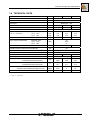
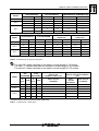
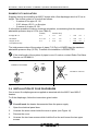
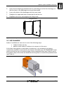
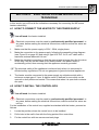
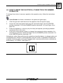
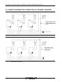
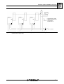
1
Installation, use and
maintenance manual
Heaters Line M C Series
Gas fired unit heaters with centrifugal fan
for heating medium-large areas
Natural gas/LPG fired
EDITION: 04/2007
Code: D-LBR447
This manual has been prepared and printed by Robur S.p.A.; whole or partial reproduction
of this manual is prohibited.
The original is filed on the premises of Robur S.p.A.
Any use of this manual other than for personal consultation must be previously authorised
by Robur S.p.A.
The rights of those who have legitimately filed the registered trademarks contained within
this publication are not affected.
With the aim of continuously improving the quality of its products, Robur S.p.A. reserves
the right to modify the data and contents of this manual without prior notice.
Preface
INTRODUCTION
This manual is intended for those who must install and use the Robur M C series warm air
heaters.
It is directed to the hydraulic system installation technicians who must install the heater,
the electrical system installation technicians who must connect the heater to the main
power supply and to the end users who must verify its normal operation.
The manual is also for service technicians with indications of maintenance and technical
assistance operations.
Summary
The manual is divided into six sections:
Section 1 is for the user, the hydraulic system installation technician, the electrical
system installation technician and the service technician. It provides general warnings
and observations, technical data and the manufacturing characteristics of the M C series
heaters.
Section 2 is for the user. It provides all the information that is necessary to use the M C
series heaters correctly.
Section 3 is for the hydraulic installation technician. It provides all the information that
is necessary for the correct installation of the M C series heaters.
Section 4 is for the electrical system installation technician. It provides all the
information that is necessary to make the electrical connections for the M C series
heaters.
Section 5 is for service technicians. It provides instructions for regulating gas flow and
for changing gas type. It also contains information regarding maintenance.
Section 6 is for the user, the hydraulic system installation technician, the electrical
system installation technician and the service technician. It contains information about
accessories available for the M C series heaters.
For rapid access to the sections, refer to the relative graphical icons (see Table 2)
indicated in the right-hand margin of the odd-numbered pages.
Ed. 04/2007
3
M C Series – Warm air heaters – Installation, Operation and Maintenance Manual
Meaning of icons
The icons contained in the margin of the manual have the following meanings.
Danger signal
)
Warning
Notes
Start of operating procedure
Reference to another part of the manual or to another
manual/booklet
Table 1 – Descriptive icons
Section 1: Overview and technical characteristics
Section 2: User
Section 3: Hydraulic system installation technician
Section 4: Electrical system installation technician
Section 5: Technical assistance and maintenance
Section 6: Accessories
Table 2 – Section icons
4
Ed. 04/2007
Index of contents
INDEX OF CONTENTS
SECTION 1: OVERVIEW & TECHNICAL CHARACTERISTICS .......................................7
1.1 GENERAL ADVICE............................................................................................................................ 7
1.2 NOTES ON OPERATION OF THE APPLIANCE............................................................................... 9
1.3 MANUFACTURING CHARACTERISTICS ...................................................................................... 10
CONTROL AND SAFETY COMPONENTS ............................................................................... 10
1.4 TECHNICAL DATA .......................................................................................................................... 11
1.5 DIMENSIONS OF M C SERIES HEATERS .................................................................................... 12
SECTION 2: USER ...........................................................................................................13
2.1 HOW TO SWITCH THE HEATER ON AND OFF ............................................................................ 13
WINTER OPERATION (HEATING) ........................................................................................... 13
SWITCHING OFF ...................................................................................................................... 14
SUMMER OPERATION (VENTILATION).................................................................................. 14
SEASONAL SWITCH-OFF ........................................................................................................ 14
SECTION 3: HYDRAULIC SYSTEM INSTALLATION TECHNICIAN ..............................15
3.1 GENERAL APPLIANCE INSTALLATION PRINCIPLES.................................................................. 15
3.2 INSTALLATION SEQUENCE .......................................................................................................... 15
3.3 SIZING OF COMBUSTION AIR AND FLUE PIPES ........................................................................ 17
EXAMPLE OF CALCULATION.................................................................................................. 24
3.4 INSTALLATION OF FLUE DIAPHRAGM......................................................................................... 24
3.5 AIR CHANGES................................................................................................................................. 25
3.6 WALL INSTALLATION WITH SUPPORT BRACKET ...................................................................... 26
SECTION 4: ELECTRICAL SYSTEM INSTALLATION TECHNICIAN ............................27
4.1
4.2
4.3
4.4
4.5
4.6
4.7
HOW TO CONNECT THE HEATER TO THE POWER SUPPLY ................................................... 27
HOW TO INSTALL THE CONTROL BOX ....................................................................................... 27
HOW TO CONNECT THE THERMOSTAT TO THE HEATER........................................................ 28
HOW TO MAKE THE ELECTRICAL CONNECTION FOR SUMMER OPERATION ...................... 29
ASSEMBLY WIRING DIAGRAM...................................................................................................... 30
OPERATION WIRING DIAGRAM.................................................................................................... 31
ELECTRICAL CONNECTION DIAGRAM FOR SUMMER/WINTER SWITCH AND
PROGRAMMABLE TIMER .............................................................................................................. 31
4.8 WIRING DIAGRAM FOR CONNECTION OF SEVERAL HEATERS .............................................. 32
SECTION 5: TECHNICAL ASSISTANCE AND MAINTENANCE ....................................35
5.1 HOW TO REGULATE THE GAS VALVE......................................................................................... 35
OPERATION WITH NATURAL GAS ......................................................................................... 35
OPERATION WITH L.P.G. GAS................................................................................................ 36
REGULATION OF SOFT OPENING (FOR M 60 C HEATERS)................................................ 36
5.2 HOW TO CHANGE GAS TYPE ....................................................................................................... 38
5.3 MAINTENANCE ............................................................................................................................... 39
5.4 OPERATING ANOMALIES .............................................................................................................. 39
5.5 TYPES OF FAULT AND POSSIBLE ACTIONS .............................................................................. 39
CASE NO. 1: THE UNIT LOCKS OUT DURING THE FIRST IGNITION PHASE. .................... 39
CASE NO. 2: THE UNIT LOCKS OUT DURING OPERATION. ................................................ 40
CASE NO. 3: THE TEMPERATURE LIMIT THERMOSTAT (M1) STOPS THE BURNER. ....... 40
CASE NO. 4: THE BURNER GOES OUT AND DOES NOT RE-IGNITE EVEN IF ROOM
TEMPERATURE REQUIRES IT................................................................................................. 40
CASE NO. 5: THE EXHAUST FAN WILL NOT START.............................................................. 40
CASE NO. 6: THE EXHAUST FAN STARTS BUT THE UNIT DOES NOT IGNITE. ................. 41
SECTION 6: ACCESSORIES...........................................................................................45
Ed. 04/2007
5
M C Series – Warm air heaters – Installation, Operation and Maintenance Manual
MIXING CHAMBER ................................................................................................................... 45
FILTER HOLDER....................................................................................................................... 45
AIR FILTER ................................................................................................................................ 46
AIR FLOW ADJUSTMENT DAMPERS...................................................................................... 46
ANTI-VIBRATION JOINTS......................................................................................................... 47
LOWER SUPPORT BEAMS ...................................................................................................... 47
SUPPORT BRACKETS ............................................................................................................. 47
6
Ed. 04/2007
Overview and general characteristics
SECTION 1:
OVERVIEW & TECHNICAL CHARACTERISTICS
In this section you will find general indications to follow regarding the installation and use
of the M C series heaters, a brief overview of the operation of the heaters, their
manufacturing characteristics and technical data.
1.1 GENERAL ADVICE
This manual is an integral and essential part of the product and must be delivered to the
final user.
This appliance must be used only for the purposes for which it has been expressly
designed for. All other uses are considered inappropriate and therefore dangerous.
The manufacturer does not accept any contractual or extra contractual liability for damage
caused by errors in installation or use and in any case by failure to observe the
instructions supplied by the manufacturer.
The appliance must be installed in compliance with current regulations.
Do not obstruct either the intake hole or the outlet grilles of the fan.
In the case of failure and/or poor operation of the appliance, deactivate it (disconnect
)the
power supply and close the gas valve), and refrain from any attempt to repair or
intervene directly upon the appliance.
Any product repairs must only be carried out by a Technical Assistance Centre
authorised by the manufacturer, and using only original spare parts.
Failure to observe the instructions above may compromise the safety of the appliance.
To guarantee the efficiency and correct operation of the appliance it is essential to have
annual maintenance carried out by professionally qualified personnel, observing the
manufacturer’s instructions.
Professionally qualified personnel means personnel that have specific technical
expertise in the sector of heating plant components for civil use. In any case the user
may obtain all necessary information by contacting ROBUR S.p.A. Customer Service
Department (tel. 0039 035 888111).
If the appliance is sold or transferred to a different owner, ensure that this manual
accompanies the appliance, so that it may be consulted by the new owner or installation
technician.
Before starting the heater, have professionally qualified personnel check that:
-
mains power and gas mains data correspond to data on the appliance’s data
plate;
-
the flue pipe is functioning efficiently;
-
combustion air is supplied and exhaust gases are expelled correctly in
accordance with current regulations;
-
the gas supply plant is correctly sealed both internally and externally;
-
fuel intake flow is regulated in accordance with the power required by the heater;
Ed. 04/2007
7
M C Series – Warm air heaters – Installation, Operation and Maintenance Manual
-
the heater is supplied with fuel type for which it is set up for;
-
the fuel supply pressure is within the values given on the data plate;
-
the fuel supply plant is sized for the flow required by the heater and that it is
equipped with all of the safety and control devices prescribed by current
regulations.
Do not use gas pipes to ground electrical devices.
Do not leave the heater connected to the power supply unnecessarily when not in use,
and close the gas valve.
If the appliance is not to be used for a long period, close the heater’s main gas supply
valve and disconnect it from the power supply.
IF YOU SMELL GAS
• Do not use electrical switches, telephones or any other object or device that
can cause sparks.
• Close the gas valve.
• Open doors and windows immediately in order to create an air current to
ventilate the room.
• Contact professionally qualified personnel for assistance.
8
Ed. 04/2007
Overview and general characteristics
1.2 NOTES ON OPERATION OF THE APPLIANCE
The M C series warm air heater is an independent heating appliance with a sealed circuit,
forced draught type.
It has been designed to be installed inside the room to be heated and warm air is
distributed through a connected air duct.
It can operate with natural gas (G20) and L.P.G. (G30/G31) (appliance belonging to
category II2H3+ in compliance with norm EN 1020).
The combustion circuit is sealed off from the environment to be heated and complies with
the requirements of norm EN 1020 for type C appliances: intake of combustion air and
outlet of exhaust gases occur outdoor and are ensured by the operation of a blower which
is located in the combustion circuit. The appliance is approved also as a type B appliance
for installations where the combustion air intake is permitted directly from the room to be
heated.
The operation of the generator is controlled by a thermostat, available as an accessory.
When heat is required, the electronic control unit ignites the burner.
An electrode detects when ignition has occurred. If there is no flame, the electronic control
unit stops the appliance.
The combustion products pass through the heat exchangers internally the unit. The heat
exchangers receive externally the flow of air produced by the centrifugal fan causing warm
air to circulate in the room.
The centrifugal fan starts automatically only when it receives the command from the
ventilation thermostat, that is, only when the exchangers are hot, in order to prevent cold
air from being introduced into the room. It stops when the exchangers are cold.
If the heat exchangers should overheat, because of abnormal operation, a limit thermostat
is fitted in the unit which, if required, cuts off power to the gas valve, which then cuts off
the flow of fuel and causes the burner to switch off. The limit thermostat can be reset
manually.
The limit thermostat may be reset only by professionally qualified personnel when
) the
cause of overheating has been identified.
If the air intake or flue pipes are obstructed, or if the flue fan does not function properly,
the differential manostat intervenes, causing the stop of the gas valve and the subsequent
switching off of the heater.
If during the summer period the operation of only the fan(s) is required, it is possible to
replace the command supplied as standard with a command with a summer/winter switch
(available as an accessory).
Ed. 04/2007
9
M C Series – Warm air heaters – Installation, Operation and Maintenance Manual
1.3 MANUFACTURING CHARACTERISTICS
M C series heaters are supplied with:
-
atmospheric burner, patented by ROBUR, in AISI 430 stainless steel
-
combustion product extractor for forced draught of combustion products
-
cylindrical combustion chamber in AISI 409 stainless steel, manufactured with
non-welded seams
-
heat exchanger, patented by ROBUR, in aluminium alloy with high heat
exchange capacity with horizontal finns (air side) and vertical finns (flue side)
-
self-supporting structure in sheet stainless steel painted with RAL 2008 orange
epoxy powder
-
connector flange for connection to warm air distribution ducting
-
centrifugal fan for introducing warm air into the room
-
control box with lock out signal and reset button
CONTROL AND SAFETY COMPONENTS
10
-
100 °C manual reset limit thermostat to protect against overheating of the heat
exchangers
-
manual reset safety thermostat to protect against overheating of the electrical
panel
-
fan thermostat to control the start-up of the fan only when the exchangers are
hot, to prevent cold air being blown into the room
-
differential manostat to control the correct expulsion of combustion products
-
gas electro valve: if a safety device intervenes (e.g. limit thermostat, safety
thermostat, etc.) the gas valve is locked out electrically with the consequent block
of gas flow to the burner.
• Voltage:
230 V - 50 Hz
• Operating temperature range:
0 °C up to +60 °C
• Model:
SIT 830 Tandem (for models 20 and 30)
SIT 826 Tandem (for models 60)
-
electronic flame control unit for controlling the ignition of the main burner and
checking for presence of a flame by means of an ionisation-based electrode. If no
flame is present, the device causes the gas valve to be closed.
Ed. 04/2007
Overview and general characteristics
1.4 TECHNICAL DATA
MODEL
U.M.
M20 C
M30 C
APPLIANCE CATEGORY
M60 C
II2H3+
APPLIANCE TYPE
C12 – C32 – B22
GAS TYPE
Natural gas – LPG
NOMINAL HEAT INPUT
kW
20.6
34.8
72.5
NOMINAL HEATING OUTPUT
kW
18.3
30.7
63.8
PRESSURE HEAD
Pa
NOMINAL GAS CONSUMPTION
(15° C – 1013 mbar)
NATURAL GAS
L.P.G. G30
L.P.G. G31
NOMINAL EFFICIENCY
FUEL SUPPLY PRESSURE
NATURAL GAS
L.P.G. G30
L.P.G. G31
GAS INLET DIAMETER
110
3
m /h
kg/h
kg/h
218
1.62
1.59
3.68
2.74
2.69
7.67
5.72
5.61
%
88.8
88.2
88
20
28/30
37
mbar
”
1/2
3/4
COMBUSTION AIR INTAKE PIPE DIAMETER
mm
130
FLUE PIPE DIAMETER
mm
110
VOLTAGE
230V – 50 Hz
INSTALLED ELECTRICAL POWER
W
FUSE
A
AIR FLOW RATE(1) AT MAXIMUM PRESSURE DROP
AT MINIMUM PRESSURE DROP
THERMAL HEAD
AT MAXIMUM PRESSURE DROP
AT MINIMUM PRESSURE DROP
SOUND PRESSURE LEVEL AT 6 METRES
IN FREE-FIELD CONDITIONS (MAX FLOW)
WEIGHT
600
620
920
m3/h
1600
2900
3100
4300
5800
7600
K
34
18.7
29.3
21.1
32.6
24.9
dB(A)
43.5
47
50
kg
66
82
133
6.3
10.0
Table 3 – Technical data
1
At 20 °C – 1013 mbar
Ed. 04/2007
11
M C Series – Warm air heaters – Installation, Operation and Maintenance Manual
1.5 DIMENSIONS OF M C SERIES HEATERS
A
B
C
D
E
F
G
H
J
L
M
N
M20 C
630
947
800
490
370
405
438
431
215
284
393
95
M30 C
770
988
800
490
510
405
578
431
215
284
393
95
M60 C
1270
988
800
490
1010
405
1078
431
215
284
393
95
P
Q
R
S
T
U
V
W
X
Y
Z
M20 C
390
435
340
600
715
563
340
-
Ø EXT 113
Ø EXT 135
300
M30 C
460
435
340
600
715
580
374
-
Ø EXT 113
Ø EXT 135
324
M60 C
468
435
340
600
715
580
870
495
Ø EXT 113
Ø EXT 135
324
Table 4 – Dimensions of M C series heaters
SIDE VIEW
REAR VIEW
M 20 C and M 30 C
1
2
3
FRONT VIEW
REAR VIEW M 60 C
FLUE OUTLET
COMBUSTION AIR INTAKE
POWER CABLE IN
Figure 1 – Dimensions of M C series heaters
12
Ed. 04/2007
User
SECTION 2:
USER
In this section you will find all the indications necessary for operating the M C series
heaters correctly.
2.1
HOW TO SWITCH THE HEATER ON AND OFF
activation must be carried out by professionally qualified personnel.
) Initial
Before starting the heater, have professionally qualified personnel check that:
•
•
•
•
the data on the appliance’s data plate correspond to mains power and gas
mains data;
the calibration is compatible with the power of the heater;
the pipe for expelling exhaust gases is functioning correctly;
combustion air is supplied and exhaust gases are expelled correctly in
accordance with current regulations.
Operation of the M C series heater is controlled by a thermostat, available as an
accessory.
WINTER OPERATION (HEATING)
You will need: the heater connected to the power and gas supply.
1.
Open the gas valve.
2.
Power the appliance by closing the bipolar switch.
3.
Set the thermostat to maximum.
4.
After a pre-wash time of approximately 30 seconds, the gas electro valve opens and
the ignition electrode begins to spark.
5.
When a flame is present the detector electrode stops sparking automatically,
keeping the appliance operating.
6.
If no flame is present, the central control unit stops the appliance and the red lock
out warning light A and the reset button B lights up (see Figure 2).
A LOCK OUT WARNING LIGHT
B RESET BUTTON
B
A
Figure 2 – Control box supplied as standard
7.
If point 6 occurs, press the reset button (B).
Ed. 04/2007
13
M C Series – Warm air heaters – Installation, Operation and Maintenance Manual
8.
If ignition has taken place as expected, set the thermostat to the desired
temperature.
If the burner is ignited after a prolonged period of inactivity or for the first time, it may
be necessary to repeat the operation several times as a result of air in the pipes.
SWITCHING OFF
You will need: the heater connected to the power and gas supply.
1.
To switch off the appliance, set the thermostat to minimum. The burner goes out,
while the fans continue to operate until the appliance has cooled down completely.
appliance must never be switched off by removing electrical power, as this stops
) The
the fans immediately and activates the limit thermostat, which then must be reset
manually.
SUMMER OPERATION (VENTILATION)
To change from winter to summer operation (fan operation only) easily and immediately it
is possible to substitute the control box supplied as standard with the O-CTR000
command (available as an accessory – see Figure 17) which has a summer/winter switch.
This command makes it possible to change from summer to winter operation by closing
the gas valve by placing the summer/winter switch in the summer position (the “sun”
symbol).
Alternatively, professionally qualified personnel can set up the appliance for summer
operation as shown in “HOW TO MAKE THE ELECTRICAL CONNECTION FOR
SUMMER OPERATION” on page 29.
SEASONAL SWITCH-OFF
1.
Switch off the appliance (as described in SWITCHING OFF) and wait for the fan(s)
to stop.
2.
Close the gas supply valve of the appliance.
3.
If the VENTILATION function is not to be used, cut off electrical power to the
appliance using the bipolar switch located on the power supply line.
14
Ed. 04/2007
Hydraulic system installation technician
SECTION 3:
HYDRAULIC SYSTEM INSTALLATION
TECHNICIAN
In this section you will find all the indications necessary for installing the M C series
heaters from a hydraulic point of view.
3.1 GENERAL APPLIANCE INSTALLATION PRINCIPLES
Installation must be carried out in accordance with the manufacturer’s instructions by
professionally qualified personnel;
Professionally qualified personnel means personnel that have specific technical
expertise in the sector of heating plant components. If in doubt contact Robur S.p.A.
on +39-035-888111.
Incorrect or non-compliant installation may cause damage to persons, animals or things,
for which the manufacturer cannot be held responsible.
The units must be installed according to the national and international norms regarding
this type of appliances and applications.
For installation purposes, the following regulations should be respected:
-
The distance between the rear of the appliance and the wall should be enough to
allow adequate air renewal (at least 200 mm between fan and wall). The
minimum distance from the side walls is indicated in Figure 3 on page 17.
-
The optimum height recommended from the ground to the base of the heater is
2.5 – 3.5 m (see Figure 3 on page 17). Installation of heaters at a height of less
than 2.5 metres is not recommended.
-
To obtain maximum comfort and performance from the plant, observation of the
following rules is recommended:
• make sure that the flow of air from the appliance does not strike staff directly;
• take into account the presence of obstacles (pillars and suchlike).
-
Do not install M C series heaters in greenhouses or environments with a high
degree of humidity or similar weather conditions, as they have not been designed
for this type of use.
3.2 INSTALLATION SEQUENCE
Following the installation plan, set up the gas and electricity supply lines as well as the
holes for the flue pipe and combustion air intake.
1.
Unpack the appliance, taking care to check that it has not been damaged during
transport. Each appliance is tested in the factory before being dispatched. Therefore,
if damage has occurred inform the transporter immediately.
2.
Install the support bracket (available as an accessory, see ACCESSORIES on page
45), following the instructions provided on the sheet supplied with the bracket itself.
3.
Fix the heater to the bracket using the screws supplied with the bracket.
Ed. 04/2007
15
M C Series – Warm air heaters – Installation, Operation and Maintenance Manual
4.
Check that an adequate gas supply and distribution network exists. Specifically, if
the appliance runs on:
Natural gas
the gas mains pressure must be 20 mbar (204 mm H2O) with a tolerance from 17
mbar to 25 mbar;
L.P.G. (Propane-Butane mix)
It is essential to fit a first-stage pressure reduction station in proximity to the liquid
gas tank to reduce pressure to 1.5 bar, and a second-stage pressure reduction
station for a further reduction from 1.5 bar a 30 mbar (306 mm H2O) in proximity to
the heater (with a tolerance from 20 mbar to 35 mbar);
L.P.G. (pure Propane)
It is essential to fit a first-stage pressure reduction station in proximity to the liquid
gas tank to reduce pressure to 1.5 bar, and a second-stage pressure reduction
station for a further reduction from 1.5 bar a 30 mbar (377 mm H2O) in proximity to
the heater (with a tolerance from 25 mbar to 45 mbar).
If in doubt regarding the composition of L.P.G. used, follow the indications for a
) Propane-Butane
mix.
5.
Connect the heater to the gas mains, fitting the gas supply pipe with a shut-off valve
and a three-piece pipe union.
16
Ed. 04/2007
Hydraulic system installation technician
MIN. 200 mm
Figure 3 – Clearances
3.3 SIZING OF COMBUSTION AIR AND FLUE PIPES
M C series warm air heaters are approved for installation in one of the following ways:
-
C12 type installation: expulsion of combustion products and intake of combustion
air are wall-based, via separate (see Figure 4 on page 18) or coaxial (see Figure
5 on page 18 and Figure 6 on page 19) ducts. In this way the appliance is sealed
off from the room in which it is installed.
-
C32 type installation: expulsion of combustion products and intake of combustion
air are roof-based, via separate or coaxial ducts (see Figure 7 on page 19). In
this way the appliance is sealed off from the room in which it is installed.
-
B22 type installation: intake of combustion air takes place in the room and
combustion products are expelled outside via a specific duct, which may be either
horizontal or vertical. In this way the appliance is not sealed off from the room
(see Figure 8 on page 20 and Figure 9 on page 20).
Ed. 04/2007
17
M C Series – Warm air heaters – Installation, Operation and Maintenance Manual
C12 TYPE INSTALLATION WITH SEPARATE WALL DUCTS
A
B
C
D
SEEN FROM ABOVE
H
G
F
REF.
CODE
Q.TY
A
O-TBO011
1
Flue pipe adaptor, Ø 110 mm
B
O-TBO003
1
Ø 110 mm pipe, length = 0.5 m
E
DESCRIPTION
C
O-TBO005
1
Ø 110 mm pipe, length = 1 m with intake element
D
O-12114330
1
Wall-mounted wind-protected terminal in steel, Ø 110 mm
E
O-12114340
1
Wall-mounted wind-protected terminal in steel, Ø 130 mm
F
O-TBO006
1
Ø 130 mm pipe, length = 1 m with intake element
G
O-TBO004
1
Ø 130 mm pipe, length = 0.5 m
H
O-TBO012
1
Flue pipe adapter, Ø 130 mm
-
O-FSC000
3
Pipe clamp, Ø 110 mm
-
O-FSC001
3
Pipe clamp, Ø 130 mm
O-STF009
1
Support bracket
Figure 4 – C12 type installation with separate wall-mounted ducts
M 20 C and M 30 C:
C12 TYPE INSTALLATION WITH COAXIAL WALL DUCTS
A
B
C
SEEN FROM ABOVE
D
E
REF.
CODE
Q.TY
DESCRIPTION
A
O-TBO011
1
Flue pipe adaptor, Ø 110 mm
B
O-TBO005
1
Ø 110 mm pipe, length = 1 m with intake element
C
O-SCR000
1
Wall-mounted coaxial flue pipe, Ø 150 mm
D
O-TBO012
1
Flue pipe adapter, Ø 130 mm
E
O-TBO006
1
Ø 130 mm pipe, length = 1 m with intake element
-
O-FSC000
2
Pipe clamp, Ø 110 mm
-
O-FSC001
2
Pipe clamp, Ø 130 mm
O-STF009
1
Support bracket
Figure 5 – M 20 C and M 30 C: C12 type installation with coaxial wall-mounted duct (O-SCR000)
18
Ed. 04/2007
Hydraulic system installation technician
M 60 C:
C12 TYPE INSTALLATION WITH COAXIAL WALL DUCT
A
B
C
D
SEEN FROM ABOVE
E
B
F
c
REF.
CODE
Q.TY
A
O-TBO011
1
Flue pipe adaptor, Ø 110 mm
DESCRIPTION
B
O-TPP004
2
Intake plug on flue pipes
C
O-TBO003
1
Ø 110 mm pipe, length = 0.5 m
D
O-SCR001
1
Wall-mounted coaxial flue pipe, Ø 180 mm (including pipe adaptors)
E
O-TBO012
1
Flue pipe adapter, Ø 130 mm
F
O-TBO004
1
Ø 130 mm pipe, length = 0.5 m
-
O-FSC000
2
Pipe clamp, Ø 110 mm
-
O-FSC001
2
Pipe clamp, Ø 130 mm
O-STF009
1
Support bracket
Figure 6 – M 60: C12 type installation with wall-mounted coaxial duct (OSCR001)
TYPE C32 INSTALLATION WITH ROOF-MOUNTED COAXIAL DUCT
G
F
E
CODE
Q.TY
A
O-STF009
1
Support bracket
I
L
B
DESCRIPTION
B
O-TBO004
2
Ø 130 mm pipe, length = 0.5 m
C
O-TBO012
1
Flue pipe adapter, Ø 130 mm
D
O-TBO011
1
Flue pipe adapter, Ø 110 mm
E
O-TBO003
1
Ø 110 mm pipe, length = 0.5 m
F
O-TBO006
1
Ø 130 mm pipe, length = 1 m with
intake element
G
O-SCR002
1
Wall-mounted coaxial flue pipe, Ø
180 mm (including pipe adaptors)
H
O-TBO005
1
Ø 110 mm pipe, length = 1 m with
intake element
I
O-RCC000
1
T connecter, Ø 110 mm
H
D
C
REF.
L
O-TPP000
1
Plug for T connector, Ø 110 mm for
condensate drainage
M
O-CRV002
1
90° elbow, Ø 130 mm
-
O-FSC000
5
Pipe clamp, Ø 110 mm
-
O-FSC001
4
Pipe clamp, Ø 130 mm
M
A
Figure 7 – C32 type installation with roof-mounted coaxial duct (O-SCR002)
Ed. 04/2007
19
M C Series – Warm air heaters – Installation, Operation and Maintenance Manual
B22 TYPE INSTALLATION WITH WALL-MOUNTED EXHAUST DUCT
SEEN FROM ABOVE
A
B
C
REF.
CODE
Q.TY
A
O-TBO011
1
Flue pipe adaptor, Ø 110 mm
Ø 110 mm pipe, length = 0.5 m
D
DESCRIPTION
B
O-TBO003
1
C
O-TBO005
1
Ø 110 mm pipe, length = 1 m with intake element
D
O-12114330
1
Wall-mounted wind-protected terminal in steel, Ø 110 mm
-
O-FSC000
3
Pipe clamps, Ø 110 mm
O-STF009
1
Support bracket
Figure 8 – B22 type installation with wall-mounted flue pipe
B22 TYPE INSTALLATION WITH ROOF-MOUNTED FLUE PIPE
D
E
F
B
C
REF.
CODE
Q.TY
A
O-STF009
1
Support bracket
DESCRIPTION
B
O-TBO011
1
Flue pipe adapter, Ø 110 mm
C
O-TBO003
1
Ø 110 mm pipe, length = 0.5 m
D
O-TRM000
1
Roof terminal, Ø 110
E
O-TBO001
1
Ø 110 mm pipe, length = 1 m
F
O-TBO005
1
Ø 110 mm pipe, length = 1 m with
intake element
G
O-RCC000
1
T connecter, Ø 110 mm
H
O-TPP000
1
Plug for T connector, Ø 110 mm for
condensate drainage
-
O-FSC000
6
Pipe clamps, Ø 110 mm
G
H
A
Figure 9 – B22 type installation with roof-mounted flue pipe
20
Ed. 04/2007
Hydraulic system installation technician
Ambient ventilation air can be taken wholly or partially from the outside or wholly or
partially from the inside of the room (for further information see “AIR CHANGES” on page
25).
It is necessary to use ducts approved for the type of installation to be carried out. ROBUR
S.p.A. can supply to order rigid pipes, coaxial ducts and approved terminals.
In order to size the system it is necessary to calculate the overall pressure drop generated
by the system itself.
The total pressure drop admitted by the system of pipes depends on the model of
appliance (Table 5 on page 23).
Pressure drops of the flue pipes, air pipes and coaxial pipes supplied by ROBUR are
given in Table 6 and Table 7 on page 23.
The pressure drops associated with external terminals can be ignored, as they are
extremely low.
In the project stage it must be ensured that the sum of the pressure drops of the system of
pipes is lower than the maximum pressure drop admitted by the appliance and higher than
the minimum pressure drop admitted (see Table 5). In the following pages an example of
how to carry out the calculation of the pressure drop is provided.
horizontal flue pipes over 1 metre long are installed, in order to prevent the
) Ifpotential
formation of drops of condensate reaching the appliance it is necessary to
install the flue pipe with a counter-gradient of 2 or 3 cm for each metre of its length
(see Figure 10). In addition, in order to install the external flue terminals and
combustion air intake terminals correctly, follow the instructions given in Figure 13.
gradient: 2-3 cm per metre
Figure 10 – Horizontal pipe gradient
vertical flue pipes, in order to prevent possible drops of condensate reaching the
) For
flue fan, it is necessary to fit a “T”-shaped element at the bottom of the vertical flue
pipe for the collection of condensate (Figure 7 on page 19).
If a mixing chamber is installed (available as an accessory – see ACCESSORIES on
page 45), in order that the condensate drain does not interfere with the mixing
chamber the drain must be fitted as indicated in Figure 11.
Ed. 04/2007
21
M C Series – Warm air heaters – Installation, Operation and Maintenance Manual
mixing chamber
Figure 11 – Flue pipe set-up if a mixing chamber is used
If a mixing chamber is installed (available as an accessory – see ACCESSORIES on page
45), in order to prevent combustion gases coming into contact with the heated
environment it is important to avoid positioning the flue pipe outlet within the clearance
area indicated in Figure 12.
1.5 m
1,5 m
CLEARANCE AREA
1.5 m
EXTERNAL AIR INTAKE GRILLE
ATTENTION: DO NOT POSITION THE EXHAUST OUTLET IN THE CLEARANCE AREA INDICATED
Figure 12 – Clearance area for flue pipe outlet of M C series heaters with mixing chamber
22
Ed. 04/2007
Hydraulic system installation technician
AIR DIAPHRAGM
MODEL
FLUE DIAPHRAGM
PRESSURE DROP ADMISSIBLE (PA)
HEIGHT (MM)
CODE
HEIGHT (MM)
CODE
MAXIMUM
MINIMUM
-----
-----
60
019
40
-----
84
007
-----
-----
35
23
84
007
55
013
25
-----
-----
-----
-----
-----
69
45
-----
-----
45
012
46
22
-----
-----
55
013
21
-----
M20 C
M30 C
M60 C
Table 5 – Pressure drop admissible according to the model and diaphragm fitted
PRESSURE DROP, FLUE
PIPE (Pa/m)
PRESSURE DROP, AIR
PIPE (Pa/m)
AIR DIAPHRAGM
FLUE DIAPHRAGM
H (mm)
CODE
H (mm)
CODE
Ø 110
Ø 130
Ø 110
Ø 130
-----
-----
60
019
0.46
0.20
0.17
0.07
84
007
-----
-----
1.21
0.53
0.45
0.20
84
007
55
013
1.11
0.49
0.41
0.18
-----
-----
-----
-----
4.82
2.12
1.49
0.66
-----
-----
45
012
5,49
2.42
1.73
0.76
-----
-----
55
013
5,16
2.27
1.66
0.73
MODEL
M20 C
M30 C
M60 C
N.R. = DIAMETER NOT RECOMMENDED
Table 6 – Pressure drop, air pipes and flue pipes
For each 90° elbow calculate an increase in overall length of 1.5 metres.
For each “T” element calculate an increase in overall length of 2.0 metres.
For each 45° elbow calculate an increase in overall length of 0.75 metres.
H
(mm)
CODE
H
(mm)
CODE
WALL OUTLET
(O-SCR000)
WALL
OUTLET
(O-SCR001)
ROOF OUTLET
(O-SCR002)
-----
-----
60
019
5.8
2.0
2.2
84
007
-----
-----
18.0
5.0
5.6
M30 C
M60 C
PRESSURE DROP, COAXIAL
DUCT Ø 130 FOR ALL MODELS
(Pa)*
FLUE
DIAPHRAGM
MODEL
M20 C
PRESSURE DROP, COAXIAL
DUCT Ø 100
FOR M20 C & M30 C (Pa)*
AIR
DIAPHRAGM
84
007
55
013
18.0
5.0
5.6
-----
-----
-----
-----
N.R.
29.5
33.1
-----
-----
45
012
N.R.
29.5
33.1
-----
-----
55
013
N.R.
N.R.
N.R.
N.R.= DIAMETER NOT RECOMMENDED
* PRESSURE DROPS TO BE CALCULATED INCLUDING CONNECTORS
Table 7 – Pressure drop, coaxial ducts
Ed. 04/2007
23
M C Series – Warm air heaters – Installation, Operation and Maintenance Manual
EXAMPLE OF CALCULATION
Suppose that we are installing an M30 C heater with a flue diaphragm which is 55 cm in
height. The air/flue system is to be built as follows:
- 3 metres of flue pipe, Ø 110
- 2 90° elbows, Ø 110, on flue pipe
- 2 metres of air pipe, Ø 130
It is therefore possible to make a checking calculation, remembering that the maximum
admissible pressure drop is 25 Pa (see Table 5).
Quantity
Pressure drop
flue pipe Ø 110
3m
x
1.11
Pa
=
3.33
Pa
+
90º elbows
2 x 1.5 m
x
1.11
Pa
=
3.33
Pa
+
air pipe, Ø 130
2m
x
0.18
Pa
=
0.36
Pa
=
7.02
Pa
Total pressure drop
The total pressure drop of the system of pipes (7.02 Pa) is LOWER than the maximum
admissible pressure drop (25 Pa). Therefore the installation is PERMITTED.
If the total length of the system of pipes is over 16 metres, contact Robur Pre-Sales
Service on 035-888111.
CORRECT POSITIONS
AIR
FUMES
AIR
INCORRECT POSITION
FUMES
FUMES
AIR
Figure 13 – Position of wall terminals
3.4 INSTALLATION OF FLUE DIAPHRAGM
One or more flue diaphragms are supplied as standard with the M30 C and M60 C
heaters.
To fit the diaphragm, follow the instructions given below.
You will need: the heater disconnected from the power supply.
1.
Open the electrical panel door.
2.
Unscrew the screw which holds the cover in place (see Figure 14).
3.
Remove the cover.
4.
Unscrew the two lower screws which hold the flue fan and loosen the two upper
screws.
24
Ed. 04/2007
Hydraulic system installation technician
5.
Insert the flue diaphragm between the flue outlet flange and the flue fan flange, so
that the holes in the diaphragm are turned downwards.
6.
Line up the holes of the diaphragm with the lower holes.
7.
Retighten the upper and lower screws that fix the flue fan.
8.
Reposition the cover and retighten the fixing screw.
Cover fixing screw
'
Figure 14 – Cover fixing screws
3.5 AIR CHANGES
Intake of ventilation air can occur in one of the following ways:
• intake of indoor air only;
• partial or total intake of outdoor air to renew air in the room.
In the latter case (partial or total intake of outdoor air) it is necessary to use some
components available as accessories (for further information see “ACCESSORIES”) and
make sure that the sum of pressure drops of the components fitted (see Table 8) and of
the pressure drop of the warm air distribution ducting does not exceed the pressure head
(see Table 3).
Figure 15 – M C installation with accessories for partial or total intake of outdoor air
Ed. 04/2007
25
M C Series – Warm air heaters – Installation, Operation and Maintenance Manual
COMPONENT
PRESSURE DROPS
(Pa)
CHARACTERISTICS
MIXING CHAMBERS
(ALL MODELS)
FITTED WITH ONLY REAR OPENING CLEARS
0
AIR FILTER FOR M 20 C
35
FILTER CLASS G3 (EN 779)
AIR FILTER FOR M 30 C
50
AIR FILTER FOR M 60 C
50
ADJUSTMENT DAMPERS
(ALL MODELS)
DAMPERS COMPLETELY OPEN. IF AIR INTAKE
IS PARTLY FROM OUTSIDE AND PARTLY
FROM INSIDE, A SECOND DAMPER IS
REQUIRED TO COMPENSATE AIR FLOW
10
Table 8 – Pressure drops of aeration components
3.6 WALL INSTALLATION WITH SUPPORT BRACKET
For the fitting of the Robur M C series heaters, an easy-to-fit support bracket is supplied
(see ACCESSORIES on page 45). If this accessory is not used, refer to Figure 16 which
indicates the minimum dimensions of the bracket for standard installations (without mixing
chamber). To fix the heater onto the support brackets, use 4 M10 bolts.
FRONT VIEW
A
MIN. 200 mm
B
SIDE VIEW
Figure 16
MODEL
26
M20 C
M30 C
A
370
510
B
1115
M60 C
1010
1160
Ed. 04/2007
Electrical system installation technician
SECTION 4:
ELECTRICAL SYSTEM INSTALLATION
TECHNICIAN
In this section you will find all the indications necessary for connecting the MC series
heaters electrically.
4.1 HOW TO CONNECT THE HEATER TO THE POWER SUPPLY
You will need: the heater installed.
Electrical connections must be made by professionally qualified personnel. In
any case, before making the electrical connections, make sure that the wires are
not live.
1.
Make sure that the power supply is 230V - 50Hz, single phase.
2.
Make the connection to the power supply, following the assembly wiring diagram
(see Figure 18 on page 30) and using a type H05 VVF 3x1.5 mm2 cable with a
maximum external diameter 8.4 mm.
3.
Make the electrical connection so that the ground wire is longer than the live wires.
In this way it will be the last cable to be disconnected if the power cable is
accidentally pulled, thus ensuring that the appliance remains grounded.
electrical safety of the appliance is achieved only when it is connected to
) The
efficient safety regulations. Do not use gas pipes to ground electrical appliances.
4.
The heater must be connected to the power supply via a bipolar switch with a
minimum contact gap of 3 mm. A bipolar switch is defined as one which can be
opened on both phase and neutral. This means that when it is open both contacts
are open.
4.2 HOW TO INSTALL THE CONTROL BOX
You will need: the heater installed.
Electrical connections must be made by professionally qualified personnel. In
any case, before making the electrical connections, make sure that the wires are
not live.
For the installation of the control box, supplied as standard with the heater, proceed as
follows:
1.
Locate the position where the control box is to be installed.
2.
Drill a hole in the wall in line with the fixing points of the control box.
3.
Fix the control box with two screws and rawl plugs.
Ed. 04/2007
27
M C Series – Warm air heaters – Installation, Operation and Maintenance Manual
4.
Connect the heater to the power supply and switch it on.
5.
Close the gas valve and check that after a few seconds the arrest warning light A
comes on (see Figure 2).
6.
Open the gas valve again, push the reset button B (see Figure 2) and check that the
arrest warning light switches off and that the heater starts up again.
The control cables (in particular the one connecting the heater to the control box)
) must
be protected from interference produced by the power cables. This
protection can be obtained for example by shielding the cables or by running them
through channels which are separate from those of the power cables.
The maximum length of the cable connecting the heater to the control box is 20
) metres.
4.3 HOW TO CONNECT THE THERMOSTAT TO THE HEATER
For the operation of the heater it must be connected to an ambient thermostat (available
as an accessory). For the installation of the ambient thermostat, follow the instructions
below.
You will need: the heater installed.
Electrical connections must be made by professionally qualified personnel. In
any case, before making the electrical connections, make sure that the wires are
not live.
1.
Locate the position where the ambient thermostat is to be installed, if possible
approximately 1.5 metres from the floor, away from draughts, direct sunlight, and
direct heating sources (light bulbs, flows of hot air from the appliance itself, etc.) and
if possible NOT on outer walls, in order not to falsify the temperature readings and
therefore the operation of the appliance. IN THIS WAY THE APPLIANCE WIL BE
PREVENTED FROM STARTING AND STOPPING WHEN NOT DESIRED, THUS
GUARANTEEING OPTIMAL COMFORT LEVELS IN THE ROOM. If this is not
possible, shield the ambient thermostat by placing a sheet of insulating material (e.g.
cork, polystyrene, etc.) between it and the wall.
2.
Fix the ambient thermostat to the wall.
3.
Connect the ambient thermostat to the terminal board of the heater following the
instructions provided in Figure 18 on page 30.
28
Ed. 04/2007
Electrical system installation technician
4.4 HOW TO MAKE THE ELECTRICAL CONNECTION FOR SUMMER
OPERATION
To change from winter to summer operation (fan operation only), follow the instructions
below.
You will need: the heater connected to the power and gas supply.
1.
Close the gas valve and disconnect the appliance from the power supply.
2.
Access the instrument panel and move the "electrical bridge" from the WINTER
position (terminals 1-3) to the SUMMER position (terminals 1-2) (see Figure 18 on
page 30).
3.
Power the appliance: in this way only the fan(s) will operate, providing a pleasant
movement of air in the room.
4.
At the end of the summer season, to change from summer to winter operation, it is
necessary to move the "electrical bridge" from the SUMMER position (terminals 1-2)
to the WINTER position (terminals 1-3).
Alternatively, rather than performing the operations described above, to change easily and
immediately from summer to winter operation and vice versa, it is possible to replace the
supplied control box with a command equipped with a summer/winter button (available as
an accessory - O-CTR000 - see Figure 17).
☼
Figure 17 – Control box available as an accessory (O-CTR000).
Ed. 04/2007
29
M C Series – Warm air heaters – Installation, Operation and Maintenance Manual
4.5 ASSEMBLY WIRING DIAGRAM
22
24
21
23
6
7
5
1
20
230 V - 50 Hz
Figure 18 – Assembly wiring diagram for M C series appliances (see key to Figure 19)
30
Ed. 04/2007
Electrical system installation technician
4.6 OPERATION WIRING DIAGRAM
Z1
M9
M10
Z9
M4
1 2 3 4 5 6 7 13 14 15 16 17 18 19 J6 JT1 J5 JT2
M1
NP
Q1
M2
L1
M12
230V-50HZ
P1
M12
RD
GND
CM
M
CM
M
CS
RP8 RP7
S
Q2
KEY
CM
CS
L1
M
fan condenser
flue fan condenser
arrest warning light
fan motor
(2 motors for M 60 C model)
M1 limit thermostat
M10 safety thermostat
M12 manostat contol relay
M2 ventilation thermostat
M4 flame control unit
M9 6.3 A fuse (M20 and M30), 10 A (M60)
NP differential manostat
P1 reset button
Q1
Q2
gas electrovalve
soft opening modulator
(for M 60 C model)
RD rectifier bridge
(for M 60 C model)
RP7 ignition electrode
RP8 detector electrode
S
flue fan motor
Z1 summer/winter switch (optional)
Z9 ambient thermostat (optional)
Figure 19 – Operation wiring diagram for M C series heaters
4.7 ELECTRICAL CONNECTION DIAGRAM FOR SUMMER/WINTER
SWITCH AND PROGRAMMABLE TIMER
Z1
Z8
summer/winter switch
(optional)
programmable timer
(optional)
Figure 20 – Wiring diagram for summer/winter switch and programmable timer
Ed. 04/2007
31
M C Series – Warm air heaters – Installation, Operation and Maintenance Manual
4.8 WIRING DIAGRAM FOR CONNECTION OF SEVERAL HEATERS
RL1
HEATER
Z9
L
RL2
HEATER
TA
N
P
HEATER
Z9
L
RL3
TA
N
Z9
L
P
=
TA
=
RL1-2-3 =
TA
PROGRAMMABLE TIMER
AMBIENT THERMOSTATS
PROGRAMMED CONTROL
RELAY
N
I
N
L
230 V - 50 Hz
Figure 21 - Wiring diagram for several heaters with a single programmable timer and several ambient thermostats
TA
RL1
RL2
RL3
P
P
= PROGRAMMABLE TIMER
TA
= AMBIENT THERMOSTATS
RL1-2-3 = PROGRAMMED
CONTROL RELAY
L
N
L
N
L
N
I
N
L
Figure 22 - Wiring diagram for several heaters with a single programmable timer and a single ambient thermostat
(solution with several relays)
32
Ed. 04/2007
Electrical system installation technician
TA
RL
HEATER
HEATER
Z9
L
N
HEATER
Z9
L
N
P
Z9
L
P
= PROGRAMMABLE TIMER
TA
= AMBIENT THERMOSTATS
RL1-2-3 = PROGRAMMED
CONTROL RELAY
N
I
N
L
230 V - 50 Hz
Figure 23 - Wiring diagram for several heaters with a single programmable timer and a single ambient thermostat
(solution with a single relay)
Ed. 04/2007
33
M C Series – Warm air heaters – Installation, Operation and Maintenance Manual
34
Ed. 04/2007
Technical assistance and maintenance
SECTION 5:
TECHNICAL ASSISTANCE AND MAINTENANCE
In this section you will find all the indications necessary for service technicians to carry out
regulation of the gas valve and change of gas type, as well as some indications regarding
maintenance.
5.1 HOW TO REGULATE THE GAS VALVE
For the proper operation of the M C series heaters, the calibration values of the gas valve
must be the same as those given in Table 9 or in Table 10.The appliance leaves the
factory with the gas valve already calibrated. If regulation is necessary, proceed as
follows.
Regulation of the gas valve must be carried out by professionally qualified
personnel.
OPERATION WITH NATURAL GAS
You will need: the heater installed and connected to the power and gas supply.
1.
Connect a pressure gauge to the pressure intake P1 (see Figure 26).
2.
Switch on the heater.
3.
Remove the protective cover and turn the adjustment screw (see A in Figure 24 or B
in Figure 25) clockwise to increase pressure or anticlockwise to reduce it, until the
pressure indicated in Table 9 is reached.
4.
Switch the heater off and on and check that the pressure to the burner has
stabilised. If necessary adjust it again.
5.
In the case of M 60 C heaters, proceed with regulation of soft opening (see
“REGULATION OF SOFT OPENING (FOR M 60 C HEATERS)”.
regulation has been completed, the adjustment screw of the gas valve must be
) After
sealed.
PRESSURES AT THE BURNER OF SERIES M C APPLIANCES FUELLED BY NATURAL GAS (G20)
(GAS SUPPLY PRESSURE 20 mbar)
PRESSURE at the BURNER
(mbar)
(mmH2O)
M 20 C
M 30 C
M 60 C
11.8
120
7.8
80
8.0
82
Table 9 – Pressures at the burners for M C series appliances fuelled by natural gas (G20)
Ed. 04/2007
35
M C Series – Warm air heaters – Installation, Operation and Maintenance Manual
OPERATION WITH L.P.G. GAS
You will need: the heater installed and connected to the power and gas supply.
Check that the adjustment screw, B, is tightened (see Figure 24 or Figure 25). If it is not,
tighten it completely. Pressure at the burner is now directly in relation to the mains gas
supply pressure; therefore ensure that mains pressure is 30 mbar (for G30 gas) or 37
mbar (for G31 gas). Mains gas pressure can be reduced by means of a suitable first-stage
pressure reduction station, in proximity to the liquid gas tank, in order to reduce the
pressure to 1.5 bar, and a second-stage pressure reduction station, from 1.5 bar to 0.03
or 0.037 bar, in proximity to the heater but also outside the building.
In the case of M 60 C heaters, proceed with the regulation of soft opening (see
“REGULATION OF SOFT OPENING (FOR M 60 C HEATERS)”.
PRESSURES AT THE BURNER FOR SERIES M C APPLIANCES FUELLED BY L.P.G. (G30 – G31)
(GAS SUPPLY PRESSURE 30 – 37 mbar)
PRESSURE at the BURNER
(mbar)
(mmH2O)
M 20 C
M 30 C
M 60 C
28.5
291
28
286
27.5
281
Table 10 – Pressures at the burner for M C series appliances fuelled by L.P.G. (G30 – G31)
D
C
E
B
A) Pressure regulator
B) Connector for measurement
of intake gas pressure
C) Slow/Soft opening regulation
D) Electrical power connectors
E) Connector for measurement
of intake gas pressure
A
Figure 24 – Sit 830 Tandem Valve (for M 20 C and M 30 C)
REGULATION OF SOFT OPENING (FOR M 60 C HEATERS)
To regulate soft opening, proceed as follows (see Figure 25):
1.
Disconnect power from the SMD coil (D). The heater will adjust itself to the soft
opening pressure.
2.
Keeping the nut B fixed, regulate the soft opening pressure to the value indicated in
Table 11 by means of screw A (using a screwdriver).
3.
Replace the plastic cover C.
4.
Reconnect the SMD coil (D).
36
Ed. 04/2007
Technical assistance and maintenance
regulation has been completed, the adjustment screw of the gas valve must be
) After
sealed.
G
C
D
G
E
A
F
B
A)
B)
C)
D)
E)
F)
G)
Soft opening adjustment
Nut for regulation of pressure at the burner
Adjustment screw protection
Electrical connector SMD soft opening coil
Connector for measurement of intake gas pressure
Connector for measurement of outlet gas pressure
Electrical power connectors
Figure 25 – Sit 826 Tandem Valve (for M 60 C)
PRESSURES AT THE BURNER FOR SOFT OPENING
M 60 C
NATURAL GAS (G20)
L.P.G. (G30 – G31)
3.9
40
14.1
143
PRESSURE at the BURNER (mbar)
(mmH2O)
Table 11 – Pressures at the burner for soft opening on M 60 C series appliances
P1 Connector for
P1
Figure 26 – Connector for measurement of gas pressure
Ed. 04/2007
37
M C Series – Warm air heaters – Installation, Operation and Maintenance Manual
5.2 HOW TO CHANGE GAS TYPE
You will need: the heater connected to the power and gas supply.
Change of gas type must be carried out by professionally qualified personnel.
Incorrect or careless assembly of the gas circuit may cause dangerous gas leaks
from all of the circuit and in particular from zones that are tampered with. Use, in
addition, adequate sealants on all connections.
If the type of gas indicated by the label does not correspond to the one to be used, the
appliance must be converted and adapted to the type of gas to be used.
To carry out this operation, proceed as follows:
1.
Disconnect the gas and power supply.
2.
Replace the nozzles with ones of a suitable diameter for the type of gas to be used
(see Table 12). Remember to fit the copper washers located between nozzle and
manifold.
3.
Next proceed with regulation of the appliance as described in “HOW TO REGULATE
THE GAS VALVE”.
4.
Replace the sticker indicating the type of gas applied to the appliance with one
indicating the new type of gas.
NATURAL GAS AND L.P.G. NOZZLES
M 20 C
M 30 C
M 60 C
Natural gas (G20)
diameter (mm)
2.80
4.00
4.00
GPL (G30-G31)
diameter (mm)
1.6/1.8
2.20
2.2/2.3
Table 12 – M C series nozzles
38
Ed. 04/2007
Technical assistance and maintenance
5.3 MAINTENANCE
Careful maintenance is always at the basis of economy and safety.
Maintenance for heating units must be carried out, preferably at the beginning of winter,
by qualified service engineers.
For correct, prolonged operation, general cleaning of the appliance is recommended at
least once a year (giving particular attention to the heat exchangers and fan grilles), as
well as combustion tests as applicable under specific regulations.
5.4 OPERATING ANOMALIES
Before checking for possible failures, ensure that:
A) Correct electric supply: 230-240V ±10% 50Hz and adequate earthing are provided.
B) The gas is supplied.
C) Pressures and flows are within the limits recommended by the manufacturer. A
pressure lower than the given limits will result in insufficient gas inlet. The causes for
this may be the following:
If the unit is fed with natural Gas:
a) Poor gas meter performance.
b) The length of the pipes and the number of elbows are excessive with respect to the
diameter.
If the unit is fed with L.P.G.:
a) It can happen that after the first time the burner turns off, the unit locks out at the
moment of ignition. In this case it may be that the reducer flow is insufficient.
b) If the required pressure is not reached, it may be either that the meter does not
provide adequate flow or the length of the pipes and the number of elbows are
excessive with respect to the diameter.
Only at this point proceed with the specific trouble shooting.
WARNING
Before opening the side door to access the control panel, CUT OUT THE
POWER SUPPLY to the unit using the omnipolar switch.
5.5 TYPES OF FAULT AND POSSIBLE ACTIONS
In case of a failure, call a qualified service engineer.
CASE NO. 1: THE UNIT LOCKS OUT DURING THE FIRST IGNITION
PHASE.
D) The ignition electrode is broken or badly positioned.
E) The flame sensor is broken or incorrectly positioned or touches the unit ground.
NOTE
For correct burner ignition, the distance of the ignition electrode from the burner head
should be between 4 mm and 6 mm.
Ed. 04/2007
39
M C Series – Warm air heaters – Installation, Operation and Maintenance Manual
F)
G)
H)
I)
J)
Failure in the flame control unit or in its electrical connections.
Failure in the gas valve or in its electrical connections.
Soft opening pressure too low.
Check that the unit has a good earth.
Air is inside the gas pipes.
CASE NO. 2: THE UNIT LOCKS OUT DURING
OPERATION.
K) The gas supply is suddenly cut off due to a failure in the gas system. The ignition
control repeats the ignition cycle, after which the gas valve closes locking out the unit
(accidental gas inlet cut off).
L) The power supply is suddenly cut off due to a failure in the electrical supply mains. If
the electrical cut off period is prolonged, the temperature limit thermostat (M1) locks
out the unit, thus preventing re-ignition. When electricity returns, push the reset button
which is placed on the thermostat, inside the unit control panel, below the black screw
plug (accidental power supply break).
M) The flame sensor touches the unit ground or it is disconnected.
N) The gas valve does not open due to a failure of the valve itself or of its electrical
connections.
CASE NO. 3: THE TEMPERATURE LIMIT THERMOSTAT (M1) STOPS THE
BURNER.
O) The heat exchangers have overheated. Check the operation of the fan, gas pressure
and nozzles.
P) The exchangers overheat due to accumulation of dirt. Clean the exchangers (dirt can
also obstruct ventilation and supply grille).
To reset the thermostat push the button placed on the thermostat inside the unit control
panel, under the black screw plug.
CASE NO. 4: THE BURNER GOES OUT AND DOES NOT RE-IGNITE EVEN IF ROOM
TEMPERATURE REQUIRES IT.
Q) Check the performance of the room thermostat and its electrical connections.
R) Check the position of the room thermostat (check that it is not influenced by external
heat sources).
CASE NO. 5: THE EXHAUST FAN WILL NOT
START.
S)
T)
U)
V)
Check that the room thermostat is set on the desired temperature.
Check the electrical connections of the exhaust fan and its capacitor.
Check integrity of the unit’s protection fuse.
Make sure that neither the limit nor the safety thermostat have operated.
40
Ed. 04/2007
Technical assistance and maintenance
CASE NO. 6: THE EXHAUST FAN STARTS BUT THE UNIT DOES NOT
IGNITE.
W) Intake and/or exhaust duct are obstructed or too long.
X) The electrical or pneumatic connections of the pressure switch are faulty
Y) The flame control unit does not start the cycle: replace the internal fuse of the flame
control unit or the control unit itself.
Z) Pressure switch out of setting: replace or adjust it.
B
E
C
D
A
A)
B)
C)
D)
E)
Safety thermostat
Temperature limit thermostat
Air pressare switch
Flame control unit
Pressure switch control relay
Figure 27 – Electrical panel
Ed. 04/2007
41
M C Series – Warm air heaters – Installation, Operation and Maintenance Manual
TROUBLESHOOTING FLOWCHART FOR UNIT HEATERS
The heater does not
start neither for heating
nor for ventilation
Main switch
ON
YES
Check the fuse. Is
it burnt-out?
Consult your
installer
Replace the
fuse
NO
NO
Open the gas supply.
Main switch
OFF
Check for
correct electric
supply and phase
Electric supply
is 230-240 V 50 Hz
YES
Phase reaches
the correct
terminal
NO
Exchange the live
wire with the
neutral wire
YES
With unit on and off
check for correct
gas pressure
NO
Is it correct as in
the installation
manual?
Correct pressure using
proper
pressure reducers (as regards
L.P.G. units) trn to the gas
supplier
YES
Place the
summer/winter
shunt on winter
NO
Summer/winter
shunt on winter?
YES
Is the unit equipped
with a timer
thermostat?
NO
YES
NO
The thermostat
requires heating
Place the ambient
thermostat on
maximum
temperature
Place the
thermostat on
heating
YES
Troubleshoot for
overheating (excessive
gas supply, fan failure,
etc...)
Replace the defective
thermostat, then
check flue fan again
NO
Replace the
defective
thermostat, then
check fan again
Does the
fan start?
Any unit
overheating?
YES
Replace the
defective press.
switch
YES
NO
NO
Is the flue
fan live?
Continues
on page 21
42
NO
Check for
correct
ambient
thermostat
operation. Is
the contact
open?
YES
YES
YES
YES
Check for correct
temp. limit thermostat
operation.
Is the contact open?
NO
Check for correct
safety thermostat
operation. Is the
contact open?
NO
Check the
pressure switch
for correct
operation.
Pressure switch
locked out in
N.A. position?
NO
Check installation
conditions.
1) Pipe length
2) Combustion air
restrictor
3) Pipe clogging
4) Pressure switch
silicone pipe
obstructed. Reset the
thermostat if necessary.
Replace the flue fan
capacitor. If the failure
persists, replace the fuse.
Ed. 04/2007
Technical assistance and maintenance
continued
Does the flue fan
stop and go?
YES
Replace the anti-welding
device of pressure switch
NO
Replace the
ignition electrode
Replace the
fuse
NO
Does the electrode start
sparking in the burner
after 30 seconds?
NO
YES
Check the ignition electrode and
related cable. Is the electrode
properly positioned and does the
cable touch any of the unit's metal
parts?
YES
YES
Replace the
control unit…
Is the control unit
fuse broken?
YES
Reset the
control unit
Reverse the supply
connection (live and
neutral)
Replace the flame
sensor…
NO
The burner starts but
stops soon after the end of
the spark train
YES
Check the phase.
Is it correct?
YES
YES
NO
Check the flame sensor.
Is it bent
or does it touch the burner?
Replace the
control unit…
Restart the
control unit
NO
Locate the causes for
gas supply failure
Replace the
gas valve
NO
NO
The burner starts
(or gas is present)
YES
YES
Check gas supply
mains. Is there gas?
Check valve voltage. Is
there voltage in the gas
valve?
NO
Replace the ignition
control unit
YES
Replace the
thermostat
YES
NO
Fan starts after a
few minutes?
Check fan thermostat for
correct operation. Is it
locked out?
NO
Replace the capacitor. If
the failure persists,
replace the fan motor.
YES
Unit is operating
properly
Ed. 04/2007
43
M C Series – Warm air heaters – Installation, Operation and Maintenance Manual
44
Ed. 04/2007
Accessories
SECTION 6:
ACCESSORIES
This section contains a list of accessories available for the installation and use of the M C
series heaters.
) For pressure drops associated with the accessories, refer to Table 8 on page 26.
MIXING CHAMBER
The mixing chamber allows the ventilation air intake to be connected to the outside.
The chamber is ready to fit on the rear part of the heater and allows it to be connected to
both rear and lower air intake ducts. Removable blind panels are fitted on the side to allow
the centrifugal fan to be serviced.
CHAMBER FOR
M 20 C
O-CSS000
CHAMBER FOR
M 30 C
O-CSS001
CHAMBER FOR
M 60 C
O-CSS002
FILTER HOLDER
The filter holders allow the air filters to be installed.
The filter holders can be installed either behind or below the mixing chamber.
Ed. 04/2007
FILTER HOLDER
400 X 500
FOR M 20 C
O-STF014
FILTER HOLDER
500 X 500
FOR M 30 C
O-STF015
FILTER HOLDER
500 X 1,000
FOR M 60 C
O-STF016
45
M C Series – Warm air heaters – Installation, Operation and Maintenance Manual
AIR FILTER
Class G3 air filter (EN 779) to be fitted in the special filter holder.
For M 60 series heaters, two filters must be used for each intake side (rear or lower).
AIR FILTER
400 X 500
FOR M 20 C
O-FLT013
AIR FILTER
500 X 500
FOR M 30 C
O-FLT012
AIR FILTER
500 X 1,000
FOR M 60 C
N. 2
O-FLT012
AIR FLOW ADJUSTMENT DAMPERS
The dampers allow the adjustment of intake air in the rear or lower part.
The dampers can be installed either behind or below the mixing chamber.
The damper(s) must never be completely closed, as this would mean an absence of air
intake on the part of the centrifugal fan.
DAMPERS
400 X 500
FOR M 20 C
O-SRR000
DAMPERS
500 X 500
FOR M 30 C
O-SRR001
DAMPERS
500 X 1,000
FOR M 60 C
46
O-SRR002
Ed. 04/2007
Accessories
ANTI-VIBRATION JOINTS
These make it possible to connect the rear and front combustion air intake ducts to the
mixing chamber, preventing potential vibrations.
ANTI-VIBRATION JOINT
400 X 500
FOR M 20 C
O-GTV018
ANTI-VIBRATION JOINT
500 X 500
FOR M 30 C
O-GTV019
ANTI-VIBRATION JOINT
500 X 1,000
FOR M 60 C
O-GTV020
LOWER SUPPORT BEAMS
These enable the heater/mixing chamber combination to be fixed to the support bracket.
LOWER SUPPORT BEAMS
FOR M 20 C
O-SPP004
LOWER SUPPORT BEAMS
FOR M 30 C
O-SPP005
LOWER SUPPORT BEAMS
FOR M 60 C
O-SPP006
SUPPORT BRACKETS
M 20 C
M 30C
M 60 C
O-STF017
SUPPORT BRACKETS
Ed. 04/2007
47
05/04/2007
07 MED PSS 019
Codice: D-LBR447 Rev. A
Muoverci dinamicamente,
nella ricerca, sviluppo e diffusione
di prodotti sicuri, ecologici, a basso consumo
energetico, attraverso la consapevole responsabilità
di tutti i collaboratori.
La Mission Robur
Robur Spa
tecnologie avanzate
per la climatizzazione
Via Parigi 4/6
24040 Verdellino/Zingonia (Bg) Italy
T +39 035 888111 F +39 035 884165
www.robur.it
[email protected]