1
7212 9700 – 12/2004 US/CA(EN)
For registered installers
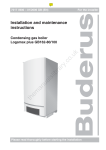
Installation and Servicing instructions
Condensing gas heater
Logamax plus GB142-24/30/45/60
CAUTION!
Before putting the appliance into operation read this manual carefully.
WARNING!
Improper installation, adjustment, alteration, service or maintenance
can cause injury, loss of life or property damage. Refer to this manual.
For assistance or additional information consult a qualified installer,
service agency or the gas supplier.
CAUTION!
The operating manual is part of the documentation that is delivered to
the installation's operator. Go through the information in this manual
with the owner/operator and make sure that he or she is familiar with
all the necessary operating instructions.
Warning: If the information in these instructions is
not followed exactly, a fire or explosion may result
causing property damage, personal injury or death.
– Do not store or use gasoline or other flammable vapors and
liquids in the vicinity of this or any other appliance.
– What to do if you smell gas
• Do not try to light any appliance
• Do not touch any electrical switch; do not use any phone in
your building.
• Immediately call your gas supplier from a neighbor’s phone.
Follow the gas supplier’s instructions.
• If you cannot reach your gas supplier, call the fire department.
– Installation and service must be performed by a qualified
installer, service agency or the gas supplier.
Notice:
This manual must be retained for future reference.
Please read thoroughly before installing and servicing
Preface
About these instructions
These Installation and Servicing Instructions contain
important information for the safe and professional
installation, start-up and maintenance of the appliance
with appliance capacities 24, 30, 45 and 60 kW.
These Installation and Servicing Instructions are
intended for specialist installers, who have the necessary training and experience for working on heating and
gas systems.
Subject to technical changes!
Slight changes may be made to the illustrations, process
steps and technical data as a result of our policy of
continuous improvement.
Updating of documentation
Please contact us if you have any suggestions for
improvements or corrections.
We reserve the right to make any changes due to technical modifications!
2
Buderus Hydronic Systems • http://www.buderus.net
Installation and Servicing instructions Logamax plus GB142-24/30/45/60 • Version 12/2004
Contents
1
1.1
1.2
1.3
1.4
1.5
1.6
Safety and general instructions . . . . . . . . . . 5
Designated use . . . . . . . . . . . . . . . . . . . . . . . . 5
Hazard definitions . . . . . . . . . . . . . . . . . . . . . . 5
The following instructions must be observed . . 5
Observe these instructions for heating
system water . . . . . . . . . . . . . . . . . . . . . . . . . . 6
Tools, materials and additional equipment . . . 6
Disposal . . . . . . . . . . . . . . . . . . . . . . . . . . . . . . 6
2
Regulations and guidelines . . . . . . . . . . . . . 7
3
Product description . . . . . . . . . . . . . . . . . . . . 8
4
Dimensions and connections . . . . . . . . . . . . 9
5
5.1
5.2
Packaging and transportation . . . . . . . . . . 11
Scope of delivery . . . . . . . . . . . . . . . . . . . . . . 11
Transporting the appliance . . . . . . . . . . . . . . 11
6
6.1
6.2
6.3
6.4
Installation . . . . . . . . . . . . . . . . . . . . . . . . . . 12
Requirements for the installation room . . . . . 12
Fitting the appliance. . . . . . . . . . . . . . . . . . . . 12
Making the gas connection . . . . . . . . . . . . . . 13
Fitting the heating circuit supply and
return pipes . . . . . . . . . . . . . . . . . . . . . . . . . . 14
Combustion Air and Ventilation Openings . . . 17
Installation of the flue gas adapter
(included in the scope of delivery) . . . . . . . . . 18
Installation of the Exhaust and
Air Intake system. . . . . . . . . . . . . . . . . . . . . . 18
6.5
6.6
6.7
7
Connecting the condensate water drain . . 23
8
8.1
Electrical connections. . . . . . . . . . . . . . . . . 24
External connection board connections . . . . . 24
9
9.1
9.2
9.3
9.4
9.5
Start-up procedure. . . . . . . . . . . . . . . . . . . . 27
Testing for gas leaks . . . . . . . . . . . . . . . . . . . 28
Filling the appliance . . . . . . . . . . . . . . . . . . . . 28
Filling the condensate trap. . . . . . . . . . . . . . . 29
Venting the gas supply valve . . . . . . . . . . . . . 29
Checking the combustion air/flue gas
connection . . . . . . . . . . . . . . . . . . . . . . . . . . . 30
Checking the orrifices . . . . . . . . . . . . . . . . . . 30
Inlet gas pressure . . . . . . . . . . . . . . . . . . . . . 30
Checking and adjusting the gas/air ratio . . . . 31
Carrying out a tightness test in operating
conditions. . . . . . . . . . . . . . . . . . . . . . . . . . . . 33
Measuring the carbon monoxide
content (CO) . . . . . . . . . . . . . . . . . . . . . . . . . 33
Function testing . . . . . . . . . . . . . . . . . . . . . . . 33
Measuring the ionization current . . . . . . . . . . 33
Installing the casing . . . . . . . . . . . . . . . . . . . . 35
Informing the owner, handing over the
technical documents . . . . . . . . . . . . . . . . . . . 35
9.6
9.7
9.8
9.9
9.10
9.11
9.12
9.13
9.14
10
10.1
10.1.1
10.1.2
BC10 basic controller . . . . . . . . . . . . . . . . . 36
Operating the BC10 basic controller . . . . . . . 36
Switching the heating system on and off . . . . 36
Displaying the operating conditions of
the burner and resetting the burner or
resetting burner faults . . . . . . . . . . . . . . . . . . 36
We reserve the right to make any changes due to technical modifications!
10.1.3 Displaying the heating system status
and/or faults. . . . . . . . . . . . . . . . . . . . . . . . . . 37
10.2 Carrying out additional tasks . . . . . . . . . . . . . 39
10.2.1 Carrying out a flue gas test . . . . . . . . . . . . . . 39
10.2.2 Selecting partial load operation
(e. g. during flue gas testing) . . . . . . . . . . . . . 39
10.2.3 Switching the heating system to
manual mode. . . . . . . . . . . . . . . . . . . . . . . . . 39
10.3 Configuring the appliance . . . . . . . . . . . . . . . 40
10.3.1 Adjusting the heating capacity. . . . . . . . . . . . 40
10.3.2 Setting the DHW temperature value . . . . . . . 41
10.3.3 Entering the heater water temperature . . . . . 41
10.3.4 Setting the pump post-purge period . . . . . . . 41
11
11.1
11.2
Shutting down the system . . . . . . . . . . . . . 43
Shut down the heating system using
the control unit . . . . . . . . . . . . . . . . . . . . . . . . 43
Shutting down the heating system
in the event of an emergency . . . . . . . . . . . . 43
12
12.1
12.2
Inspection . . . . . . . . . . . . . . . . . . . . . . . . . . 44
Preparing the appliance for inspection . . . . . 44
Visual inspection for general signs of
corrosion . . . . . . . . . . . . . . . . . . . . . . . . . . . . 44
12.3 Internal tightness testing . . . . . . . . . . . . . . . . 45
12.4 Measuring the ionization current . . . . . . . . . . 45
12.5 Measuring the inlet gas pressure . . . . . . . . . 45
12.6 Checking and adjusting the gas/air ratio . . . . 45
12.7 Carrying out a gas tightness test in
operating conditions . . . . . . . . . . . . . . . . . . . 45
12.8 Measuring the carbon monoxide
content (CO) . . . . . . . . . . . . . . . . . . . . . . . . . 45
12.9 Carrying out a pressure test of the
heating system . . . . . . . . . . . . . . . . . . . . . . . 45
12.10 Checking the functioning and the safety
of the air intake and flue gas conduit. . . . . . . 45
12.11 Checking venting systems. . . . . . . . . . . . . . . 45
13
13.1
13.2
Maintenance. . . . . . . . . . . . . . . . . . . . . . . . . 46
Cleaning the heat exchanger, burner
and condensate trap . . . . . . . . . . . . . . . . . . . 46
Checking and adjusting the gas/air-ratio . . . . 48
14
14.1
Servicing . . . . . . . . . . . . . . . . . . . . . . . . . . . 49
Checking the UBA3 fuse;
replace if necessary . . . . . . . . . . . . . . . . . . . 49
14.2 External connection board fuse . . . . . . . . . . . 49
14.3 Checking the fan unit; 120 VAC control . . . . 50
14.4 Checking the fan unit;
Supply cord (120 VAC) . . . . . . . . . . . . . . . . . 51
14.5 Checking the fan unit; Tacho cable . . . . . . . . 52
14.6 Replacing the fan unit . . . . . . . . . . . . . . . . . . 52
14.7 Checking the supply/return/safety/
hot-water temperature sensors . . . . . . . . . . . 53
14.8 Replacing the supply/return/safety sensors . 54
14.9 Checking the supply/return/
safety sensors cable . . . . . . . . . . . . . . . . . . . 55
14.10 Checking the hot surface ignitor; Control . . . 56
14.11 Checking the hot surface ignitor; resistance . 57
Buderus Hydronic Systems • http://www.buderus.net
Installation and Servicing Instructions Logamax plus GB142-24/30/45/60 • Version 12/2004
3
Contents
14.12 Checking the hot surface ignitor;
Supply cord . . . . . . . . . . . . . . . . . . . . . . . . . .
14.13 Replacing the hot surface ignitor . . . . . . . . .
14.14 Testing the ionization current . . . . . . . . . . . .
14.15 Checking the ionization electrode; cable . . .
14.16 Checking the ionization electrode;
replace if necessary . . . . . . . . . . . . . . . . . . .
14.17 Checking the gas control valve; cable
connections . . . . . . . . . . . . . . . . . . . . . . . . . .
14.18 Checking the gas control valve; Control . . . .
14.19 Checking the gas control valve; Cable
connection between gas control valve
and UBA3 installation base . . . . . . . . . . . . . .
14.20 Ohming out the gas control valve . . . . . . . . .
14.21 Replacing the gas control valve . . . . . . . . . .
14.22 Checking the control unit;
connections to the appliance . . . . . . . . . . . .
14.23 Transformer; checking and if necessary
replacing . . . . . . . . . . . . . . . . . . . . . . . . . . . .
14.24 Automatic air purging system; replacing . . . .
14.25 Burner; replacing. . . . . . . . . . . . . . . . . . . . . .
14.26 Sight glass; replacing . . . . . . . . . . . . . . . . . .
14.27 Condensate trap; replacing . . . . . . . . . . . . . .
14.28 Pressure sensor; replacing . . . . . . . . . . . . . .
14.29 Heat exchanger; replacing . . . . . . . . . . . . . .
14.30 UBA3; replacing . . . . . . . . . . . . . . . . . . . . . .
57
58
59
60
61
62
62
62
64
65
68
70
72
73
76
77
77
78
85
15
Converting the appliance to propane
or high altitude conversion . . . . . . . . . . . . 86
16
16.1
16.2
16.3
17.1
17.2
17.3
Appendix . . . . . . . . . . . . . . . . . . . . . . . . . . .
Operating messages . . . . . . . . . . . . . . . . . . .
Error messages. . . . . . . . . . . . . . . . . . . . . . .
Technical specifications . . . . . . . . . . . . . . . .
Start-up report . . . . . . . . . . . . . . . . . . . . . . . .
Inspection report . . . . . . . . . . . . . . . . . . . . . .
Maintenance report . . . . . . . . . . . . . . . . . . . .
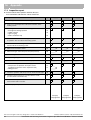
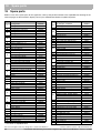
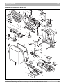
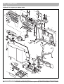
18
Spare parts . . . . . . . . . . . . . . . . . . . . . . . . . 94
19
Index. . . . . . . . . . . . . . . . . . . . . . . . . . . . . . . 97
87
87
88
89
91
92
93
We reserve the right to make any changes due to technical modifications!
4
Buderus Hydronic Systems • http://www.buderus.net
Installation and Servicing Instructions Logamax plus GB142-24/30/45/60 • Version 12/2004
Safety and general instructions
1
1
Safety and general instructions
Please observe these instructions in the interest of your
own safety.
1.1
Designated use
The appliance was designed for heating water for a
heating system and generating hot water e.g. for
domestic purposes.
The appliance is delivered with a BC10 basic controller
and the "Universal Automatic Burner Control Unit 3"
(UBA3) pre-installed.
The appliance can be fitted with a modulating room thermostat from the RC series or an On/Off thermostat or
relay panel end switch (24 V) (accessories).
1.2
Hazard definitions
The following defined terms are used throughout the
documentation to bring attention to the presence of
hazards of various risk levels. Notices give important
information concerning the life of the product.
DANGER:
Indicates the presence of hazards that will
cause severe personal injury, death or
substantial property damage.
WARNING:
Indicates the presence of hazards that can
cause severe personal injury, death or
substantial property damage.
CAUTION:
Indicates presence of hazards that will or
cause minor personal injury or property
damage.
CAUTION:
Risk of electric shock.
Indicates presence of hazards due to electric shock.
NOTICE:
Indicates special instructions on installation, operation or maintenance that are
important but not related to personal injury
or property damage.
We reserve the right to make any changes due to technical modifications!
1.3
The following instructions must be
observed
– The appliance must only be used for its designated
purpose, observing the Installation and Servicing
Instructions.
– Only use the appliance in the combinations and with
the accessories and spares listed.
– Other combinations, accessories and consumables
must only be used if they are specifically designed for
the intended application and do not affect the system
performance and the safety requirements.
– Maintenance and repairs must only be carried out by
authorized professionals.
– You must report the installation of a condensing gas
heater to the relevant gas utility company and have it
approved.
– You are only allowed to operate the condensing gas
heater with the combustion air/flue gas system that
has been specifically designed and approved for this
type of appliance.
– Please note that local permission for the flue system
and the condensate water connection to the public
sewer system may be required.
You must also observe:
– the local building regulations stipulating the
installation rules.
– the local building regulations concerning the air intake
and outlet systems and the chimney connection.
– the regulations for the power supply connection.
– the technical rules laid down by the gas utility
company concerning the connection of the gas burner
fitting to the local gas main.
– the instructions and standards concerning the safety
equipment for the water/heating system.
– the Installation Instructions for building heating
systems.
– The appliance must be located in an area where
leakage of the tank or connections will not result in
damage to the area adjacent to the appliance or to
lower floors of the structure. When such locations
cannot be avoided, it is recommended that a suitable
drain pan, adequately drained, be installed under the
appliance. The pan must not restrict combustion air
flow.
– Do not restrict or seal any air intake or outlet
openings.
– If you find any defects, you must inform the owner of
the system of the defect and the associated hazard in
writing.
Buderus Hydronic Systems • http://www.buderus.net
Installation and Servicing Instructions Logamax plus GB142-24/30/45/60 • Version 12/2004
5
1
Safety and general instructions
DANGER
if flammable gas explodes.
Beware if you smell gas: there may be an
explosion hazard!
1.5
Warning: If the information in these
instructions is not followed exactly, a fire
or explosion may result causing property
damage, personal injury or death.
For the installation and maintenance of the appliance
you will need the standard tools for central heating, gas
and water fitting.
Tools, materials and additional
equipment
z Do not store or use gasoline or other
flammable vapors and liquids in the
vicinity of this or any other appliance.
In addition, a handtruck with a fastening belt is very
useful.
What to do if you smell gas
1.6
z Do not try to light any appliance.
– Dispose of the appliance packaging in an
environmentally sound manner.
– Dispose of components of the heating system
(e. g. appliance or control device), that must be
replaced, by handing them in to an authorized
recycling facility.
z Do not touch any electrical switch; do not
use any phone in your building.
z Immediately call your gas supplier from a
neighbor’s phone. Follow the gas
supplier’s instructions.
Disposal
z If you cannot reach your gas supplier,
call the fire department.
Installation and service must be performed
by a qualified installer, service agency or the
gas supplier.
1.4
Observe these instructions for
heating system water
– Thoroughly flush the system prior to filling.
Only use untreated main water to fill and top off the
system.
– Do not use salt bedding exchangers to soften the
water.
– Do not use inhibitors or other additives!
– No Toxic chemicals such as used for boiler treatment,
shall be introduced into the portable water used for
space heating.
– The maximum permissible flow rate of the
GB142-24/30 this is 11 GPM (gal./min.), for the
GB142-45 is 15 GPM and for the GB142-60 is
20 GPM.
– When using oxygen-permeable pipes, e. g. for floor
heating systems, you must separate the system using
heat exchangers. Unsuitable heating system water
promotes the formation of sludge and corrosion.
This may damage the heat exchanger or affect its
operation.
We reserve the right to make any changes due to technical modifications!
6
Buderus Hydronic Systems • http://www.buderus.net
Installation and Servicing Instructions Logamax plus GB142-24/30/45/60 • Version 12/2004
Regulations and guidelines
2
2
Regulations and guidelines
The installation must be conform to the requirements of
the authority having jurisdiction or, in the absence of
such requirements, to the latest edition of the National
Fuel Gas Code, ANSI Z223.1. In Canada, installation
must be in accordance with the requirements of
CAN/CGA B149.1 or 2 Installation Code for Gas Burning
Appliances and Equipment.
Where required by the authority having jurisdiction, the
installation must conform to the Standard for Controls
and Safety Devices for Automatically Fired Boilers,
ANSI/ASME CSD-1.
Install CO detectors per local regulations. Appliance
requires yearly maintenance, see maintenance section
see chapter 13 "Maintenance", page 46
Operating Limits of the appliance:
Max. appliance temperature:
220 °F (105 °C)
Max. operating pressure:
44 psi (3 bar)
The hot water distribution system must comply with all
applicable codes and regulations. When replacing an
existing appliance, it is important to check the condition
of the entire hot water distribution system to ensure safe
operation.
We reserve the right to make any changes due to technical modifications!
Buderus Hydronic Systems • http://www.buderus.net
Installation and Servicing Instructions Logamax plus GB142-24/30/45/60 • Version 12/2004
7
3
Product description
3
Product description
6
6
7
7
8
9
10
11
8
5
9
10
11
5
12
4
4
13
12
3
3
2
2
9
9
1
14
15
16
1
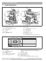
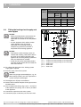
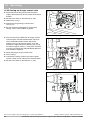
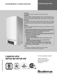
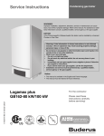
Fig. 1
Logamax plus GB142-24/30 (left) and GB142-45/60 (right)
pos. 1: Drawer with control unit
pos. 2: Universal Burner Automat (UBA3)
pos. 3: Control unit BC10
pos. 4: Gas valve
pos. 5: Cover
pos. 6: Flue measuring points
pos. 7: Parallel flue
2 3
4
90
110
120
90
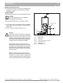
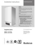
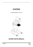
Fig. 2
pos. 1:
pos. 2:
pos. 3:
pos. 4:
pos. 5:
pos. 6:
130
170
190
12 11 10
Basic Controller Logamatic BC10
Main switch
DHW temperature knob
LED "DHW status"
Display
Heating water temperature knob
LED "Heating system status"
9
8
7
pos. 7: Under the cover a RC system controller can be installed.
Only when the appliance is used for outdoor weather responsive
operation.
pos. 8: LED "Burner Operation"
pos. 9: Service Tool connector
pos. 10: "Service" button
pos. 11: "Chimney sweep" button
pos. 12: "Reset" button Switching the heating system on and off
We reserve the right to make any changes due to technical modifications!
8
Burner
Latches of which two have locks
Sighting glass
Heat exchanger
Back cover
Air intake for the fan
Fan
Condensate trap
External Connection Board (under the cover)
150
130
140
1
pos. 8:
pos. 9:
pos. 10:
pos. 11:
pos. 12:
pos. 13:
pos. 14:
pos. 15:
pos. 16:
15 13 16
5 6
110
100
14
Buderus Hydronic Systems • http://www.buderus.net
Installation and Servicing Instructions Logamax plus GB142-24/30/45/60 • Version 12/2004
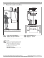
Dimensions and connections
Dimensions and connections
6.2"
(158 mm)
22" (560 mm)
4.7" (119 mm)
A
7.5" (190 mm)
13.2" (335 mm) 4.3" (110 mm)
3" (75 mm)
F G
3" (75 mm)
D E
6" (150 mm)
18.7" (475 mm)
16" (420 mm)
6" (150 mm)
1.8" (46 mm)
B
C
2.2" (55 mm)
28" (712 mm)
0.25"
(6 mm)
3" (75 mm)
4" (100 mm)
1.2" (30 mm)
20" (500 mm)
12" (300 mm)
4
4
> 6"
(150 mm)
> 4"
(100 mm)
Fig. 3
Dimensions and connections for appliance GB142-24/30 (dimensions in inches)
LA (B) = Air intake (inside diameter 3'')
AA (A) = Flue gas connection (inside diameter 3'')
RK (G) = Return, Ø 1.1” 1 (Ø 28 mm)
AKO (E) = Condensate water outlet, Ø 1.3” (Ø 32 mm)
VK (F) = Supply, Ø 1.1” 1 (Ø 28 mm)
GAS (D)= outside diameter
Gas connection, ¾” NPT
WB (C) = Wall bracket
1
One Ø 1.1” (Ø 28 mm) inside x 1'' NPT threaded compression fitting is.
NOTICE
Observe the lateral minimum distances of the
appliance (4” = 100 mm) and the necessary
distances (24” (600 mm) at the front and
12” (300 mm) at the top) for removing the
casing and service accessibility.
Closet clearances are:
4” (100 mm) to the right, 4” (100 mm) at the top
and 6” (150 mm) to the left.
We reserve the right to make any changes due to technical modifications!
Buderus Hydronic Systems • http://www.buderus.net
Installation and Servicing Instructions Logamax plus GB142-24/30/45/60 • Version 12/2004
9
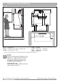
Dimensions and connections
6.2"
(158 mm)
13.2" (335 mm)
28" (712 mm)
0.25"
(6 mm)
7.5" (190 mm)
4.7" (119 mm)
4" (100 mm)
35.4" (900 mm)
4.3" (110 mm)
A
B
9.7" (246 mm)
C
16" (420 mm)
1.2" (30 mm)
20" (500 mm)
12" (300 mm)
4
D E
F
G
20.7" (526 mm)
3" (75 mm)
3" (75 mm)
18.7" (475 mm)
2.2" (55 mm)
1.8" (46 mm)
> 4"
(100 mm)
> 6"
(150 mm)
Fig. 4
Dimensions and connections for appliance GB142-45/60 (dimensions in inches)
LA (B) = Air intake
AA (A) = Combustion air
RK (G) = Return, Ø 1.1” 1 (Ø 28 mm)
AKO (E) = Condensate water outlet, Ø 1.3” (Ø 32 mm)
VK (F) = Supply, Ø 1.1” 1 (Ø 28 mm)
GAS (D)= Gas connection, ¾” NPT
WB (C) = Wall bracket
1
One Ø 1.1” (Ø 28 mm) inside x 1'' NPT threaded compression fitting is delivered enclosed.
NOTICE
Observe the lateral minimum distances of the
appliance (4” = 100 mm) and the necessary
distances (24” (600 mm) at the front and
12” (300 mm) at the top) for removing the
casing and service accessibility.
Closet clearances are:
4” (100 mm) to the right, 4” (100 mm) at the top
and 6” (150 mm) to the left.
We reserve the right to make any changes due to technical modifications!
10
Buderus Hydronic Systems • http://www.buderus.net
Installation and Servicing Instructions Logamax plus GB142-24/30/45/60 • Version 12/2004
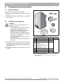
Packaging and transportation
5
Packaging and transportation
5.1
Scope of delivery
5
The appliance is delivered fully assembled.
z When receiving the delivery, check if the packaging
is intact.
2
1
z Check that all the items listed in table 1 are included
in the delivery.
5.2
3
Transporting the appliance
4
CAUTION
The appliance may be damaged when it is
improperly secured.
– Only transport the appliance using the right
transportation equipment, such as a
handtruck with a fastening belt or special
equipment for manoeuvering steps.
– During transportation the appliance must
be secured on the transportation equipment
to prevent it from falling off.
– Protect all parts against impacts if they are
to be transported.
– Observe the transportation markings on the
packaging.
5
6
Fig. 5
Items supplied with unit
Pos. Parts
z Packaged heaters must always be lifted and carried
to their destination by two people, or you must use a
handtruck or special equipment to transport them to
their destination.
z Transport the appliance to the room where it is to be
installed.
1
Appliance with casing
1
2
Wall bracket
1
3
Technical documents 1
including:
- User's Instructions
- Installation and Servicing
instructions
- wall mounting template
3
4
Compression fittings
2
5
Room thermostat
1
6
Flue gas adapter
1
Table 1
1
We reserve the right to make any changes due to technical modifications!
Quantity Packaging
1 box
Items supplied with unit
The user’s instructions (in a special format) is located in the
appliance drawer
Buderus Hydronic Systems • http://www.buderus.net
Installation and Servicing Instructions Logamax plus GB142-24/30/45/60 • Version 12/2004
11
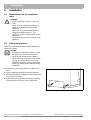
6
Installation
6
Installation
6.1
Requirements for the installation
room
DANGER
– Install the heating system in a frost-free
room.
– Do not store any flammable materials or
liquids in the immediate vicinity of the
appliance.
– Never use any chlorinated detergents or
halogenated hydrocarbons (e. g. in
spraycans, solvents and detergents, paints,
adhesives).
– Do not allow too much dust to collect on the
appliance.
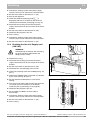
6.2
Fitting the appliance
Observe the installation distances of the combustion
air/flue gas system.
NOTICE
– To protect the connection orifice you must
not remove the styropor bottom panel.
– Do not lift the appliance by the drawer.
– Do not remove the transport safety clamps
(see fig. 6) from the drawer at this time.
– Protect the appliance and the combustion
air/flue gas orifice against pollution during
installation.
z Remove the packaging materials and dispose of
them.
z Use the mounting template to mark the drill holes.
z Install the wall bracket taking into account the necessary service clearances.
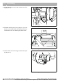
z Remove the transport safety clamps (fig. 6) taking
into account the necessary service clearances.
Fig. 6
We reserve the right to make any changes due to technical modifications!
12
Removing the transport safety clamps
Buderus Hydronic Systems • http://www.buderus.net
Installation and Servicing Instructions Logamax plus GB142-24/30/45/60 • Version 12/2004
Installation
6
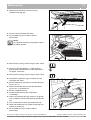
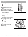
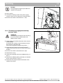
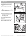
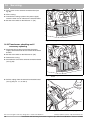
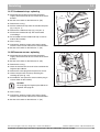
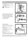
z Use the radiator key to unlock the two latches a
quarter turn (fig. 7, pos. 1).
2
3
z Open the latches (fig. 7, pos. 2).
2
z Remove the casing by lifting it upwards and then
pulling it forwards (fig. 7, pos. 3); do not hold it by the
latches.
1
z Hold the appliance by the rear appliance casing and
place it on the wall bracket.
z Level out the appliance.
2
2
Fig. 7
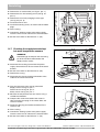
6.3
Removing the casing
Making the gas connection
DANGER
Only carry out work on gas conduits and
fittings if you are licensed for such work.
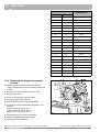
z Determine proper size gas pipe for the installation
using table 2 and table 3. Do not forget the pipe fitting
losses and observe proper size of the fittings.
1
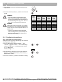
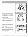
z Install the furnished ¾” gas cock on the gas connection.
z Connect the gas pipe to the gas cock (fig. 8, pos. 1)
so that it is free from any strain.
Fig. 8
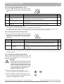
Length of
pipe (feet)
NOTICE
When installing the gas supply connection, it
must comply with local regulations or, if such
regulations do not exist, with the National
Fuel Gas Code, ANSI Z 223.1.
In Canada, the gas supply connection
must comply with local regulations or, if such
regulations do not exist, with
CSA/CGA-B149 Installation Guidelines.
10
1
Gas Volume Capacity
(ft3 / hr) 1
¾"
1"
1 ¼"
1 ½"
278
520
1,060
1,600
20
190
350
730
1,100
30
152
285
590
890
40
130
245
500
760
50
115
215
440
670
75
93
175
360
545
100
79
160
305
480
150
64
120
250
380
Table 2
We reserve the right to make any changes due to technical modifications!
Making the gas connection
Gas Pipe Capacity for different pipe sizes
Maximum pipe capacity in ft3/hr, based on a specific gravity of
.60 (42 mbar) and a inlet gas pressure of .5 psi (35 mbar) or less
and a pressure drop of .3 inches W.C. (20 mbar)
Buderus Hydronic Systems • http://www.buderus.net
Installation and Servicing Instructions Logamax plus GB142-24/30/45/60 • Version 12/2004
13
6
Installation
Steel pipe
diameter
in inches
Equivalent length for Pipe Fittings in feet
Type of pipe fitting
90°-Elbow
Tee
Gate valve Gas cocks
(flow thru
branch)
Equivalent length in feet
¾
2.1
4.1
0.5
1.25
1
2.6
5.2
0.6
1.60
1¼
3.5
6.9
0.8
2.15
1½
4.0
8.0
0.9
2.50
Table 3
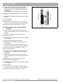
6.4
Equivalent length for pipe fittings in feet
Fitting the heating circuit supply and
return pipes
NOTICE
– Piping and components connected to the
water appliance for the space heating
application are suitable for use with potable
water.
– A water appliance which will be used to
supply potable water shall not be
connected to any heating system or
component(s) previously used with a
nonpotable water heating appliance.
NOTICE
– To protect the entire heating system we
recommend installing a dirt particle filter in
the return circuit. When connecting the
appliance to an existing heating system this
filter must definitely be installed.
– Install shut-off valves immediately before
and after the dirt particle filter to enable the
filter to be cleaned.
z Fit a filling and drain cock in the heating system
supply pipe if required.
1
2
5
4
3
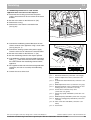
Fig. 9
pos. 1:
pos. 2:
pos. 3:
pos. 4:
pos. 5:
Pump manifold installation
Compression fitting (heating system supply pipe)
Compression fitting (heating system return pipe)
DHW supply
DHW return
Relief valve
z Also fit a safety valve in the system.
NOTICE
When using oxygen-permeable pipes, e. g. for
floor heating systems, you must separate the
system using heat exchangers.
z Thoroughly flush all pipes and radiators.
z Refer to the installation template for the pipe connection dimensions.
z Fit the compression fittings (fig. 9, pos. 1 and 2) first
to the Hydronic set (see fig. 10, 11 and 12) and then
to the appliance.
z Connect the expansion tank to the system.
z Connect the pipes so that they are free from strain.
We reserve the right to make any changes due to technical modifications!
14
Buderus Hydronic Systems • http://www.buderus.net
Installation and Servicing Instructions Logamax plus GB142-24/30/45/60 • Version 12/2004
Installation
6
Appliance with external tank
z Connect the external hot-water tank according to the
Installation instructions of the hot-water tank and
fittings concerned.
Piping examples
FLUE GAS
AIR INTAKE
The following illustrations are two Installation examples.
NOTICE
The following illustrations are simplified
conceptual illustrations only.
GB142
Piping and field components must be field verified.
pump manifold
z Install a low water cut-off (LWCO) when required by
local code or when the appliance is installed above
piping level.
5
Fig. 10 is a schematic representation of fig. 9.
1
NOTICE
If this water heater is installed in a closed water
supply system, such as one having a backflow
preventer in the cold water supply line, means
shall be provided to control thermal expansion.
Contact the water supplier or local plumbing
inspector on how to control this situation.
The seperate storage vessel must have a
temperature and pressure relief valve installed.
The relief valve shall comply with the Standard
for Relief Valves and Automatic Gas Shutoff
Devices for Hot Water Supply Systems, ANSI
Z21.22-CSA 4.4.
PT
2
3
4
Fig. 10
pos. 1:
pos. 2:
pos. 3:
pos. 4:
pos. 5:
pos. 6:
6
Schematic representation of the appliance with the
hydronic set
DHW supply
drain valve
pump manifold shut-off valves
secondary supply
DHW return
secondary return
When the system requires water for space
heating at temperatures higher than required
for other uses, a means such as a mixing valve
shall be installed to temper the water for those
uses in order to reduce scald hazard potential.
We reserve the right to make any changes due to technical modifications!
Buderus Hydronic Systems • http://www.buderus.net
Installation and Servicing Instructions Logamax plus GB142-24/30/45/60 • Version 12/2004
15
6
Installation
FLUE GAS
WARNING
No valve is to be placed between the relief
valve and the tank. Discharge of the relief
valve must be conducted to a suitable place
for disposal when relief occurs and no
reducing coupling or other restriction may be
installed in the discharge line.
AIR INTAKE
GB142
1
Optional
Additional
DHW
DHW
Tank
Tank
2
PT
3
9
4
5
6
zones
Radiant
7
Aditional zones
8
Fig. 11
pos. 1:
pos. 2:
pos. 3:
pos. 4:
Schematic representation of the appliance with the
hydraulic set connected to an optional hot water tank
with one or multiple zones including one pump and
zone valves
pressure relief valve pos. 5: secondary pump
PT meter
pos. 6: shut-off valve
(Pressure and
pos. 7: shut-off valve
temperature meter) pos. 8: zone valve
drain valve
pos. 9: primary pump
DHW pump
NOTICE
FLUE GAS
Primary pump and DHW tank pump must
have an internal check valve.
AIR INTAKE
GB142
1
Optional
Additional
DHW
DHW
Tank
Tank
2
PT
3
8
4
5
zones
Radiant
6
Aditional zones
7
Fig. 12
pos. 1:
pos. 2:
pos. 3:
pos. 4:
We reserve the right to make any changes due to technical modifications!
16
Schematic representation of the appliance with the
Hydronic set connected to an optional hot water tank
with one or multiple zones and zone pumps
pressure relief valve pos. 5: shut-off valve
PT meter
pos. 6: shut-off valve
(Pressure and
pos. 7: zone pump
temperature meter) pos. 8: primary pump
drain valve
DHW pump
Buderus Hydronic Systems • http://www.buderus.net
Installation and Servicing Instructions Logamax plus GB142-24/30/45/60 • Version 12/2004
Installation
6.5
6
Combustion Air and Ventilation
Openings
CAUTION:
APPLIANCE DAMAGE AND OPERATIONAL FAILURES !
Due to insufficient or lacking openings for
combustion air and/or ventilation of the
appliance room.
Provisions for combustion air and ventilation are always required, regardless
whether the combustion air is taken from
the outside (sealed combustion) or inside
(room air for combustion).
Insufficient ventilation of the appliance
room can lead to high air temperatures.
This can result in appliance damage.
– Make sure that intake and exhaust
openings are sufficiently sized and no
reduction or closure of openings takes
place.
– When the problem is not resolved, do
not operate the appliance.
– Please note these restrictions and its
dangers to the operator of the appliance.
WARNING:
APPLIANCE DAMAGE !
due to contaminated air.
– Appliance must be clear and free from
combustible materials, gasoline and
other flammable vapors and liquids, and
corrosive liquids and vapors.
Never use chlorine and hydrocarbon
containing chemicals (such as spray
chemicals, solution and cleaning
agents, paints, glues etc) in the vicinity
of the appliance.
– Do not store and use these chemicals in
the appliance room.
– Avoid excessive dust formation and
build-up.
NOTICE
When one expects contaminated combustion air (near swimming pools, chemical
cleaning operations and hair salons),
sealed combustion operation is recommended.
DANGER:
FIRE DANGER !
due to flammable materials or liquids.
– Do not store flammable materials and
liquids in the immediate vicinity of the
appliance.
We reserve the right to make any changes due to technical modifications!
Buderus Hydronic Systems • http://www.buderus.net
Installation and Servicing Instructions Logamax plus GB142-24/30/45/60 • Version 12/2004
17
6
Installation
All Air from Inside the Building (room air)
The closet shall be provided with two permanent openings communicating directly with an additional room(s).
The total input of all gas utilization equipment installed in
the combined space shall be considered in making this
determination. Each opening shall have a minimum free
area of 1 square inch per 1,000 Btu per hour of total
input rating of all gas utilization equipment in the
confined space, but no less than 100 square inches.
One opening shall commence within 12 inches
(300 mm) of the top, and one opening shall commence
within 12 inches (300 mm) of the bottom of the enclosure. The minimum dimension of air openings shall be
not less than 3 inches (75 mm).
All Air from Outdoor (sealed combustion)
The closet shall be provided with two permanent openings, one commencing within 12 inches (300 mm) from
the top, and one commencing within 12 inches
(300 mm) from the bottom of the enclosure. The openings shall communicate directly, or by ducts, with the
outdoors or spaces (crawl or attic) that freely communicate with the outdoors.
The minimum dimension of air openings shall be no less
than 3 inches (75 mm).
1.
Where directly communicating with the outdoors,
each opening shall have a minimum free area of
1 square inch per 4,000 Btu/hr of total input rating
of all equipment in the enclosure.
2.
Where communicating with the outdoors through
vertical ducts, each opening shall have a minimum
free area of 1 square inch per 4,000 Btu/hr of total
input rating of all equipment in the enclosure.
3.
Where communicating with the outdoors through
horizontal ducts, each opening shall have a
minimum free area of 1 square inch per
2,000 Btu/hr of total input rating of all equipment in
the enclosure.
4.
Where ducts are used, they shall be of the same
cross-sectional area as the free area of the opening
to which they connect.
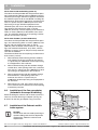
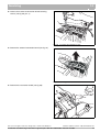
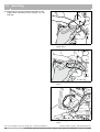
6.6
Installation of the flue gas adapter
(included in the scope of delivery)
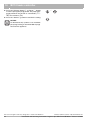
Before installing the exhaust and air intake system it is
necessay to install the flue gas adapter (see fig. 13).
z Screw on the flue gas adapter using six screws.
6.7
Installation of the Exhaust and Air
Intake system.
NOTICE:
Consult local and state codes pertaining to
special building code and fire department
requirements. Adhere to national code
requirements.
We reserve the right to make any changes due to technical modifications!
18
Fig. 13
Connecting the flue gas adapter
Buderus Hydronic Systems • http://www.buderus.net
Installation and Servicing Instructions Logamax plus GB142-24/30/45/60 • Version 12/2004
Installation
6
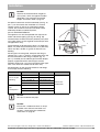
NOTICE:
Observe the listed maximum lengths of
vent system, which are appliance model
dependent. The maximum permissible
lengths are listed in table 4, page 22.
An optional concentric vent/air intake body (see fig. 15,
pos. 1) can be used for the installation of a vertical
venting system as well as for a horizontal venting
system. The concentric vent/air intake body can be
ordered by Buderus Hydronic Systems,
part no. BRYKGAVTO601CV.
The appliance can also be operated with separate air
intake and exhaust piping (see fig. 18 and fig. 20).
The termination shall be at least 3 ft (910 mm) away from
a gas utility meter, service regulator or the like (for room
air applications only).
2
1
The termination shall terminate at least 4 ft (1220 mm)
below, 4 ft (1220 mm) horizontally from, or 1 ft (305 mm)
above any door, window, or gravity air inlet into any
building.
All vent pipes must be glued, except for the flue gas
adapter (fig. 14, pos. 1) which is screwed into place and
the first connection to the flue gas adapter (fig. 14,
pos. 2). Installed you can slide the pipe onto the adapter,
properly supported and the exhaust pipe must be
pitched a minimum of a ¼ inch per foot back to the appliance. This allows the condensate to drain away.
Fig. 14
Vent pipes
All combustion air and vent pipe materials and fittings
must comply with the following:
Item
Vent or air pipe
and fitting
Pipe
cement/primer
Material
United states
PVC schedule 40
ANSI/ASTM D1785
PVC-DWV
ANSI/ASTM D2665
CPVC schedule 40
ANSI/ASTM F441
ABS-DWV schedule 40
ANSI/ASTM D2661
PVC
ANSI/ASTM D2564
CPVC
ANSI/ASTM F493
ABS
ANSI/ASTM D2235
Canada
CSA or ULC
certified only
NOTICE
Do not use cellular core pipe.
NOTICE
Ensure that a condensate drain is always
installed at the exhaust connection see
Chapter “7 Connecting the condensate
water drain” on page 23
We reserve the right to make any changes due to technical modifications!
Buderus Hydronic Systems • http://www.buderus.net
Installation and Servicing Instructions Logamax plus GB142-24/30/45/60 • Version 12/2004
19
6
Installation
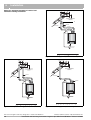
Below are approved examples of vertical and
horizontal venting installation
10"- 0" MIN
(250 mm - 0 mm MIN)
12" (300 mm) OVER MAXIMUM
SNOW LEVEL OR 24" (600 mm)
WHICHEVER IS
GREATER
1
INTAKE
EXHAUST
3" (80 mm)
3" (80 mm)
Fig. 15
Vertical venting system (sealed combustion)
10"- 0" MIN
(250 mm - 0 mm MIN)
10"- 0" MIN
(250 mm - 0 mm MIN)
12" (300 mm) OVER MAXIMUM
SNOW LEVEL OR 24" (600 mm)
WHICHEVER IS
GREATER
12" (300 mm) OVER MAXIMUM
SNOW LEVEL OR 24" (600 mm)
WHICHEVER IS
GREATER
INTAKE
EXHAUST
EXHAUST
3" (80 mm)
3" (80 mm)
3" (80 mm)
Fig. 17
Vertical parallel venting system (sealed combustion)
We reserve the right to make any changes due to technical modifications!
20
INTAKE
Fig. 16
Vertical venting system (room air only)
Buderus Hydronic Systems • http://www.buderus.net
Installation and Servicing Instructions Logamax plus GB142-24/30/45/60 • Version 12/2004
Installation
6
3" (80 mm)
INTAKE
EXHAUST
NOTICE
The condensate water must be drained in
accordance with the applicable rules.
See chapter 7 „Connecting the condensate
water drain“.
Fig. 18
Horizontal venting system (room air only)
INTAKE
INTAKE
3" (80 mm)
3"
3"(80 mm)
3" (80 mm)
3" (80 mm)
EXHAUST
Fig. 20
Horizontal venting system (sealed combustion)
EXHAUST
Fig. 19
Horizontal parallel venting system (sealed
combustion)
Do not exceed the total equivalent venting length of
100 feet (GB142-24/30/45) and 60 feet (GB142-60)
maximum requirement each for the intake and exhaust
piping.
We reserve the right to make any changes due to technical modifications!
Buderus Hydronic Systems • http://www.buderus.net
Installation and Servicing Instructions Logamax plus GB142-24/30/45/60 • Version 12/2004
21
6
Installation
See table 4 for the Friction Loss Equivalent in piping and
fittings.
Fittings or Piping
feet
m
Example:
When you end up using 3 x 45°-elbows and the concentric vent kit, then the total venting length may not exceed
88 feet (26.82 m) (GB142-24/30/45) or 48 feet (14.63 m)
(GB142-60).
45 degree elbow
3
0.91
90 degree elbow
5
1.52
plastic pipe per foot
1
0.30
concentric vent kit
3
0.91
Table 4
3 x 45°-elbow = 3 x 3 ft (0.91 m)=
9 ft (2.73 m)
concentric vent kit =
3 ft (0.91 m)
Total friction loss equivalent =
Equivalent
Friction Loss Equivalent in piping and fittings
12 ft (3.66 m)
Total venting length for this example is:
GB142-24/30/45 = 100 ft (30.48 m) - 12 ft (3.66 m)=
88 feet (26.82 m)
GB142-60 = 60 ft (18.29) - 12 ft (3.66 m) =
48 feet (14.63 m).
NOTICE
The minimum covering wall thickness is 1". The
maximum covering wall thickness is 16".
We reserve the right to make any changes due to technical modifications!
22
Buderus Hydronic Systems • http://www.buderus.net
Installation and Servicing Instructions Logamax plus GB142-24/30/45/60 • Version 12/2004
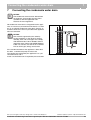
Connecting the condensate water drain
7
7
Connecting the condensate water drain
NOTICE
The condensate water must be drained from
the appliance and possibly from the flue in
accordance with the applicable rules.
Observe the local regulations.
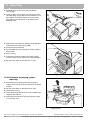
No condensate water drain is integrated into the appliance. It is necessary to install the furnished 3” x ¾” drain
tee as an external condensate water drain. See fig. 21.
Install this drain tee as close as possible to the appliance
exhaust connection.
3" (80 mm)
EXHAUST
NOTICE
INTAKE
Use materials approved by the authority
having jurisdiction. In the absence of other
authority, PVC and CPVC pipe must comply
with ASTM D1785, F441 or D2665. Cement
and primer must comply with ASTM D2564 or
F493. For Canada, use CSA or ULC certified
PVC or CPVC pipe, fittings and cement.
If the condensate outlet of the appliance is lower than
the drain, a condensate pump must be used.
The condensate produced by the appliance has a pH
value between 3 and 4.
Install a neutralization unit if required by the local code.
We reserve the right to make any changes due to technical modifications!
Fig. 21
Condensate water drain
Buderus Hydronic Systems • http://www.buderus.net
Installation and Servicing Instructions Logamax plus GB142-24/30/45/60 • Version 12/2004
23
8
8
Electrical connections
Electrical connections
Devices such as pumps, outdoor sensor and 3-way
valve are all connected to the external connection board.
The electrical connections to the appliance must be
made in accordance with all applicable local codes and
the latest revision of the National Electrical Code,
ANSI/NFPA-70
Installations should also conform with CSA C22.
1 Canadian Electrical Code Part 1 if installed in Canada.
8.1
External connection board
connections
Make all electrical connections inside the external
connection box.
z Remove the cover of the external connection box
(fig. 22).
Connecting incoming power
The appliance must be electrically grounded
in accordance with local codes, or in absence
of local codes, with the National Electrical
Code, ANSI/INFPA 70 and/or the
CSA C22.1, Electrical Code.
Fig. 22
Removing the cover from the external connection box
z Install a 120V cable to the appliance (see fig. 23,
pos. 1).
z Lead the cable through the cable guide (see fig. 23,
pos. 2).
Terminals 1 – 6 (fig. 24) are low-voltage connections
and terminals 7 – 10 (fig. 24) are 120 Volt connections.
Fig. 23
external connection board
FA
CAUTION
Risk of electric shock.
Once the main power supply is on then there
is 120V on terminals 7 – 10 (can only be
used with the correct configuration of the
control unit and specific system hydraulics),
if the main switch of the BC10 basic
controller is switched on.
1
2
RC
FW
WA EV DWV
1 2 3 4
Fig. 24
5
6
PK PS
7
PZ Netz
8
9
10
Connections to external connection board
Abbr. Color
Component
RC terminal
RC
orange
Connector for installation of an RC controller for indoor
reset operation or a module.
RC Room thermostat connection for a
module
FA
blue
Outdoor-temperature sensor
WA
green
Potential-free On/Off thermostat
FW
gray
DHW temperature sensor
EV
red
External switching contact, potential-free
for floor heating safety etc.
FA terminal
This is the terminal where you connect the outdoor
temperature sensor. Only necessary for outdoor
weather responsive operation.
DWV
green
Connection for external 3-way valve
WA terminal
PK
green
Primary loop pump 120V 60Hz
For connection of a potential free thermostat or relay
panel end switch.
PS
gray
DHW tank pump 120V 60Hz
PZ
lilac
DHW recirculating pump 120V 60Hz
FW
Netz
white
main connection 120V 60Hz
Connection for an external DHW tank sensor
We reserve the right to make any changes due to technical modifications!
24
Buderus Hydronic Systems • http://www.buderus.net
Installation and Servicing Instructions Logamax plus GB142-24/30/45/60 • Version 12/2004
Electrical connections
8
EV terminal (external switching contact)
This terminal can be used for example for the safety
switch of floor heating. This protects the floor heating
against too high appliance water temperatures (external
manual reset high limit).
The appliance is shut down when the external switching
contact is opened.
DWV
Terminal for connection of an external 3-way valve.
PK
Connector for the primary loop pump 120V 60Hz.
PS
Connector for the DHW tank pump 120V 60Hz.
PZ
Connector for the DHW recirculating pump 120V 60Hz.
Netz
Main power connector 120V 60Hz.
120-volt connections
CAUTION
Make sure that the power consumption of
each of the terminals 7 – 9 (see circuit
diagram) does not exceed 250 W.
We reserve the right to make any changes due to technical modifications!
Buderus Hydronic Systems • http://www.buderus.net
Installation and Servicing Instructions Logamax plus GB142-24/30/45/60 • Version 12/2004
25
5
Gas burner
fitting
1
L
53
79
23
1
2
3
4
Fan unit
M
45
17
1
4
5
2
3
2
3
4
5
Transformer
N 120 L
VAC
1
L
N
PE
67
68
69
13
12
14
44
16
120 VAC
N
PE
L
9
11
10
24 VRAC
6
7
2
Hot
surface
ignitor
1
120 VAC
N
120 VAC
120 VAC
24 VRAC
0 VAC
24 VAC
10 VAC
10 VAC
2
81-pole connector
(AC 0, 10, 24 and 120 V)
Earth
55
28
Pin 1
Pin 16
P
3
2
1
Pressure
sensor
81-pole connector
KIM
8
Pin 81
Pin 1
57
58
35
8
43
34
33
60
54
51
46
19
23
79
53
77
26
63
64
75
74
36
37
58
57
1
15
16
13
120 VAC
Function module
16
15
1
1
2
17
16
15
14
13
12
11
10
9
8
7
6
5
4
3
2
1
5
4
3
2
1
4
3
2
1
1
2
3
4
3
2
1
Earth
Outdoor-temperature
sensor
Modulating room controller
Bus
Function module
BC10 connector
On/Off temperature
control, potential-free
DHW sensor
External switch contact
Potential-free e.g.
for floor heating
External 3-way valve
Boiler circulator
120 VAC, max. 100 VA
Circulating pump
120 VAC, max. 100 VA
DHW circulator
120 VAC, max. 100 VA
Mains supply
120 VAC 60 Hz
Operating switch
120 VAC
Function module
L
5
6
55
3
11
2
Return sensor
12
PE L
38
1
62
61
70
16-pole connector
13
N
Ionization
Connection box UBA 3.0
Supply sensor
14
L
16-pole connector
(120 VAC)
6
white
4
7
3
49
76
230 VAC
230 VAC
27
52
25
81
80
28
1
Safety-temperature sensor
39
6
5
4
5
4
2
1
3
2
1
3
External connection for specialist servicing company
8
7
6
5
4
3
2
1
EV
FW
WA
FA
RC
PE N
L
Grid
N
14
PZ
13
25
PS
24
lilac
grey
green
PE N
L
PE N
L
PE N
white
63
PK
61
DWV
2 3
1
2
1
2
red
grey
green
blue
1
2
1
2
1
26
2
We reserve the right to make any changes due to technical modifications!
1
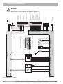
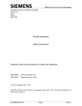
Fig. 25
orange
8
Electrical connections
WARNING
Label all wires prior to disconnection when servicing.
Wiring errors can cause improper and dangerous operation.
Electric circuit diagram
Buderus Hydronic Systems • http://www.buderus.net
Installation and Servicing Instructions Logamax plus GB142-24/30/45/60 • Version 12/2004
Start-up procedure
9
9
Start-up procedure
There are several steps involved in starting up the boiler.
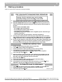
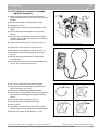
FOR YOUR SAFETY READ BEFORE OPERATING
WARNING: If you do not follow these instructions
exactly, a fire or explosion may result causing
property damage, personal injury
r or loss of life.
A. This appliance does not have a pilot. It is equipped with an ignition device
which automatically lights the burner. Do not try
r to light the burner by hand.
B.
BEFORE OPERATING smell all around the appliance area for gas. Be sure to
smell next to the floor because some gas is heavier than air and will settle on
the floor.
WHAT TO DO IF YOU SMELL GAS
Do not try
r to light any appliance.
Do not touch any electric switch; do not
use any phone in your building.
Immediately call your gas supplier from a neighbor’s phone. Follow the gas
supplier’s instruction.
If you cannot reach your gas supplier, call the fire department.
Use only your hand to push in or turn the gas control knob. Never use tools.
If the knob will not push in or turn by hand, don’t try
r to repair it, call a qualified
serv
r ice technician. Force or attempted repair may result in a fire or explosion.
D. Do not use this appliance if any parts have been under water. Immediately call a
r ice technician to inspect the appliance and to replace any part of
qualified serv
the control system and any gas control which has been under water.
C.
OPERATING INSTRUCTION
1. STOP! read the safety information above on this label.
f all electric power to the appliance.
2. Turn off
3. Set the thermostat or other operating control to lowest setting.
4. This appliance is equipped with an ignition device which
automatically lights the burner. Do not try
r to light the burner by hand.
5.
6.
7.
8.
9.
10.
Close main gas shut off
f valve.
Wait (5) minutes to clear out any gas. Then smell for gas. Including near the
floor. If you smell gas, STOP! Follow "B" in the safety information above on
this label. If you don’t smell gas, go to the next step.
Open main shut off
f valve.
Set the thermostat or other operation control to desired setting.
Turn on all electric power to the appliance.
f Gas To
If the appliance will not operate, follow the instruction "To Turn Off
Appliance" and call your serv
r ice technician or gas supplier.
TO TURN OFF GAS TO APPLIANCE
f all the electric power to the appliance if serv
r ice is to be perf
r ormed.
1. Turn off
2. Set the thermostat or other operating control to lowest setting.
708.375A - 2172B
f valve.
3. Close main gas shut off
We reserve the right to make any changes due to technical modifications!
Buderus Hydronic Systems • http://www.buderus.net
Installation and Servicing Instructions Logamax plus GB142-24/30/45/60 • Version 12/2004
27
9
9.1
Start-up procedure
Testing for gas leaks
Prior to start-up of the appliance you must check the
external tightness of the gas supply valve and confirm
this in the start-up report.
WARNING
– Cover endangered positions before leak
testing.
– Do not spray the leak testing agent onto
cables, plugs or electrical connection lines.
Do not allow it to drip onto them either.
DANGER
Leaks may be caused to pipes and screw
connections during commissioning and maintenance activities.
– Carry out a proper leak test.
– Only use approved leak detection agents
for leak detection.
z Disconnect the heating system from the power
supply.
z Check the exterior tightness of new conduit sections
up to and including the direct sealing point on the gas
burner fitting. The maximum test pressure allowed on
the input of the gas burner fitting is 60 inch W.C.
(150 mbar).
9.2
Filling the appliance
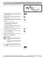
Set the main switch to "1". 3 appears in the display of
the BC10 telling you that there is no system pressure.
z Fill the heating system to a pressure of around 20 psi
(1.5 bar).
z Observe the pressure on the BC10 or the P/T gauge
in the pump manifold for the heating circuit.
The fill pressure of the system should be at least the
required inlet pressure for the expansion tank plus
7.2 psi (0.5 bar).
The minimum pressure is 15 psi (1.0 bar) (on a cold
system). The maximum pressure is 44 psi (3.0 bar)
(if the heating medium temperature is at its highest
possible level). If this pressure is exceeded, the pressure relief valve will open.
NOTICE
If a relief valve discharges periodically, this
may be due to thermal expansion in a closed
water supply system. Contact the water
supplier or local plumbing inspector on ho to
correct the situation. Do not plug the relief
valve.
For first time start up it is necessary to set the DHW
temperature knob and the heating water temperature
knob to the desired setting (see subsection 10.3.2 and
10.3.3). Factory setting is "0".
We reserve the right to make any changes due to technical modifications!
28
110
110
100
90
120
130
140
90
130
150
170
190
Buderus Hydronic Systems • http://www.buderus.net
Installation and Servicing Instructions Logamax plus GB142-24/30/45/60 • Version 12/2004
Start-up procedure
9
WARNING
There is a hot water scald potential if the BC10
is set too high.
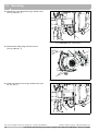
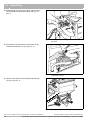
9.3
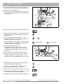
Filling the condensate trap
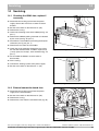
z Make sure that you fill the condensate trap with
water. This is to prevent exhaust gases from entering
the appliance.
z Remove the condensate trap (see fig. 26).
z Fill with water and refit the condensate trap in reverse
order.
Fig. 26
9.4
Filling water into the condensate trap
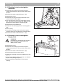
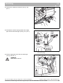
Venting the gas supply valve
z Loosen the screw plug on the testing nipple for the
gas connection and venting (fig. 27, pos. 1) by two
turns and fit a hose.
1
z Slowly open the gas shut-off valve.
z Run the gas that is discharged through a water bath.
z Close the gas shut-off valve when no more air is
released.
z Remove the hose and tighten the screw plug again.
Fig. 27
We reserve the right to make any changes due to technical modifications!
Venting the gas supply conduit
Buderus Hydronic Systems • http://www.buderus.net
Installation and Servicing Instructions Logamax plus GB142-24/30/45/60 • Version 12/2004
29
9
9.5
Start-up procedure
Checking the combustion air/flue gas
connection
Check the following points:
– Is the prescribed combustion air/flue system used?
– Have the instructions for configuring the flue system
as specified in the relevant Installation instruction for
the flue gas system been observed?
– Has an annular gap clearance measurement been
carried out as part of commissioning? Check this with
a tightness testing instrument if necessary. Were the
permissible limit values observed as specified in the
Installation Instructions for the flue gas system?
9.6
Type of gas
supply
Factory setting of gas burner fitting
Natural gas H
Delivered factory-set to Wobbe index
14.1 kWh/m3 (based on 59 °F (15 °C),
14.7 psi (=1,013 mbar)) , suitable for Wobbe
index range 11.3 – 15.2 kWh/m3.
Information on gas type instruction plate:
Set to gas category: G 20 – 2E.
Previous indications: set to Wobbe index
15.0 kWh/m3 (based on 32 °F (0 °C), 14.7 psi
(=1,013 mbar)), suitable for Wobbe index
range 12.0 – 15.7 kWh/m3.
LPG P
Suitable for propane after conversion (also
see the chapter "Conversion to another type
of gas supply").
Information on gas type instruction plate:
Set to gas category: G 31 – 3P.
Checking the orrifices
CAUTION
The burner must only be commissioned if the
correct orrifices are fitted (table 7).
Table 6
Factory setting of gas burner fitting
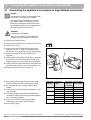
z Convert the burner fitting to another gas
type if required (see chapter 15
"Converting the appliance to propane or
high altitude conversion", page 86).
9.7
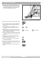
Inlet gas pressure
z Open at least one thermostatic radiator valve if
present to allow water to flow through the appliance.
Do not switch on the appliance.
z Close the gas shut-off valve. Loosen the screw plug
on the inlet gas pressure testing nipple by two turns
(fig. 28, pos. 1).
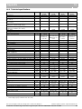
Appliance Type of gas
capacity supply
24 kW
30 kW
45 kW
60 kW
Table 7
Gas orifice
diameter
in mm (inch)
High altitude
Natural gas
4.45 (0.174)
4.65 (0.181)
LPG P
3.35 (0.131)
3.35 (0.131)
Natural gas
4.45 (0.174)
4.65 (0.181)
LPG P
3.35 (0.131)
3.35 (0.131)
Natural gas
5.35 (0.209)
5.55 (0,216)
LPG P
4.05 (0.158)
4.05 (0.158)
Natural gas
7.25 (0.283)
7.45 (0.291)
LPG P
5.35 (0.209)
4.05 (0.158)
Gas orifice diameter
z Connect the pressure gauge connection hose to the
testing nipple (fig. 28, pos. 2).
z Slowly open the gas shut-off valve.
The appliance and its individual shutoff valve must be
disconnected from the gas supply piping system during
any pressure testing of that system at test pressures in
excess of ½ psi (3.5 kPa).
The appliance must be isolated from the gas supply
piping system by closing its individual manual shutoff
valve during any pressure testing of the gas supply
piping system at test pressures equal to or less than ½
psi (3.5 kPa).
Fig. 28
We reserve the right to make any changes due to technical modifications!
30
Measuring the inlet gas pressure
Buderus Hydronic Systems • http://www.buderus.net
Installation and Servicing Instructions Logamax plus GB142-24/30/45/60 • Version 12/2004
Start-up procedure
9
z Briefly press on the control panel cover to open it.
Fig. 29
Opening the control panel
z Switch on the heating system by setting the main
switch to position "1" (see chapter 10 "BC10 basic
controller", page 36).
z Press the "Chimney Sweep" button and hold it (for
approx. two seconds) until the display shows a
decimal point.
z Measure the gas connection pressure as soon as the
"Burner" LED lights and enter this value in the startup report.
The inlet gas pressure must be:
– for natural gas - min. 6.5 – 9.6 inch W.C.
(17 – 25 mbar), nominal supply pressure
7.7 inch W.C. (20 mbar).
– for LPG - min. 8.0 inch W.C. (19.9 mbar), max.
13.0 inch W.C. (32.3 mbar), nominal supply pressure
11.0 inch W.C. (27.3 mbar)
z Repeatedly press the "Service" button until the
temperature indication is displayed.
z Press the "Chimney Sweep" button to end the
measurement procedure.
z Close the gas shut-off valve.
z Remove the connection hose again and tighten the
screw plug on the testing nipple.
z Open the gas shut-off valve again.
CAUTION
– Contact the relevant gas utility company if
the required inlet gas pressure is not
available.
– Install a gas pressure regulator before the
gas burner fitting if the supply pressure is
too high.
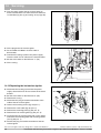
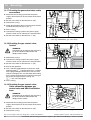
9.8
Checking and adjusting the gas/air
ratio
z Switch off the heating system using the main switch.
We reserve the right to make any changes due to technical modifications!
Buderus Hydronic Systems • http://www.buderus.net
Installation and Servicing Instructions Logamax plus GB142-24/30/45/60 • Version 12/2004
31
9
Start-up procedure
z Loosen the screw plug on the measuring nipple for
the burner pressure by two rotations (fig. 30, pos. 1).
1
z Set the pressure gauge to zero.
z Use a hose to connect the plus terminal of the pressure gauge to the burner pressure measuring nipple
(fig. 30, pos. 2).
2
Fig. 30
Checking the gas/air ratio
z Switch on the heating system using the main switch.
z Press the "Chimney Sweep" button and hold it (for
approx. two seconds) until the display shows the
decimal point.
z Press and hold the "Chimney Sweep" and
"Service" buttons (for approx. five seconds) until
the display shows "/[[" (e. g. /).
+
z Set the appliance to partial load "/" by pressing the
"Chimney Sweep" button (higher values) or the
"Reset" button (lower values).
= higher values
= lower values
z Read out the differential pressure.
The differential pressure (pGas – pAir) must be
-0.2 inch W.C. (- 5 Pa) (±0.2 inch W.C. = ± 5 Pa)
(read-out on pressure gauge: -0.4 – 0 inch W.C.=
-10 – 0 Pa).
z Enter the value measured in the start-up report.
z If the gas/air ratio is not correct it can be adjusted
using the adjustment screw (fig. 31, pos. 1). The
adjustment screw is located behind the cover screw.
Fig. 31
Setting the gas/air ratio
z Repeatedly press the "Service" button until the
temperature indication is displayed.
z Press the "Chimney Sweep" button until the
decimal point is cleared from the display.
z Switch off the heating system using the main switch.
z Remove the measurement set-up, tighten the screw
in the burner pressure measuring nipple.
z Switch on the heating system using the main switch.
We reserve the right to make any changes due to technical modifications!
32
Buderus Hydronic Systems • http://www.buderus.net
Installation and Servicing Instructions Logamax plus GB142-24/30/45/60 • Version 12/2004
Start-up procedure
9.9
9
Carrying out a tightness test in
operating conditions
z Check the tightness of all gaskets and joints in the
burner gas circuit while the burner is operational,
using a foaming agent.
DANGER
Leaks may be caused to pipes and screw
connections during start-up activities if flammable gas explodes.
– Only use approved leak detection agents
for leak detection such as a soapy water
solution.
CAUTION
due to a short circuit.
– Cover damageable parts before leak
testing.
– Do not spray the leak testing agent onto
cables, plugs or electrical connection
lines. Do not allow it to drip onto them
either.
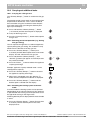
9.10 Measuring the carbon monoxide
content (CO)
z Measure the carbon monoxide content on the flue
gas sampling point (fig. 32).
The CO values in an air-free condition must be below
400 ppm or 0.04 vol. %.
Values of 400 ppm and up indicate that the burner
adjustment may be wrong, the gas burner fitting or the
heat exchanger are dirty or that there may be burner
faults.
z You must establish and resolve the cause. The appliance must be operational when you do this.
9.11 Function testing
z You must check the functioning and, if readjustment
is possible, the adjustment of all control, regulating
and safety devices when carrying out start-up tests,
annual inspections or maintenance as required.
Fig. 32
Flue gas sampling point
z You must also test the gas and water tightness.
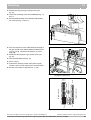
9.12 Measuring the ionization current
z Switch off the heating system using the main switch.
We reserve the right to make any changes due to technical modifications!
Buderus Hydronic Systems • http://www.buderus.net
Installation and Servicing Instructions Logamax plus GB142-24/30/45/60 • Version 12/2004
33
9
Start-up procedure
z Disconnect the plug and socket connection of the
monitoring cable and connect the measuring device
in series (fig. 33). Select the µA direct current range
on the measuring device. The measuring device
must have a resolution of at least 1 µA.
Fig. 33
Measuring the ionization current
z Switch on the heating system using the main switch.
z Press the "Chimney Sweep" button and hold it (for
approx. two seconds), until the display shows the
decimal point.
z Press and hold the "Chimney Sweep" and
"Service" buttons, until the display shows "/[["
(e. g. /).
z Set the appliance to partial load "/" by pressing the
"Chimney Sweep" button (higher values) or the
"Reset" button (lower values).
+
= higher values
= lower values
z Measure the ionization current. When the appliance
is in partial load mode the ionization current must be
> 5 µA DC.
z Enter the value measured in the start-up report.
z Repeatedly press the "Service" button, until the
temperature indication is displayed.
z Press the "Chimney Sweep" button to end the
measurement procedure.
z Switch off the heating system using the main switch.
z Remove the measuring device and restore the plug
and socket connection.
z Switch on the heating system again using the main
switch.
We reserve the right to make any changes due to technical modifications!
34
Buderus Hydronic Systems • http://www.buderus.net
Installation and Servicing Instructions Logamax plus GB142-24/30/45/60 • Version 12/2004
Start-up procedure
9
z Push against the drawer (fig. 34) to close the control
panel.
Fig. 34
Closing the control panel
Fig. 35
Installing the casing
9.13 Installing the casing
z Install the casing and close the latches (fig. 35).
Do not lift the casing by the latches!
z Lock the latches using the radiator key.
9.14 Informing the owner, handing over
the technical documents
z Show the owner how the heating system works and
how the appliance can be operated. Hand over the
technical documents.
We reserve the right to make any changes due to technical modifications!
Buderus Hydronic Systems • http://www.buderus.net
Installation and Servicing Instructions Logamax plus GB142-24/30/45/60 • Version 12/2004
35
10
10
BC10 basic controller
BC10 basic controller
10.1 Operating the BC10 basic controller
2 3
4
5 6
110
100
90
110
120
130
90
150
130
170
140
12 11 10
1
Fig. 36
pos. 1:
pos. 2:
pos. 3:
pos. 4:
pos. 5:
pos. 6:
190
9
8
BC10 basic controller – Controls
Main switch
DHW temperature knob
LED "DHW status"
Display
Heating water temperature knob
LED "Heating system status"
7
pos. 7: Under the cover a RC system controller can be
installed.
pos. 8: LED "Burner Operation"
pos. 9: Service Tool connector
pos. 10: "Service" button
pos. 11: "Chimney sweep" button
pos. 12: "Reset" button
10.1.1 Switching the heating system on and off
Switching on the heating system
z Set the main switch on the BC10 basic controller to
position "1" (On).
Switching off the heating system
z Set the main switch on the BC10 basic controller to
position "0" (Off).
10.1.2 Displaying the operating conditions of the
burner and resetting the burner or resetting
burner faults
Displaying the operating conditions of the burner
The LED indicates the operating condition of the burner.
LED Condition
On Burner
operational
Off Burner off
Table 8
Explanation
The water in the appliance is being
heated.
The water in the appliance has reached
the required temperature or there is no
heat request.
LED indication
We reserve the right to make any changes due to technical modifications!
36
Buderus Hydronic Systems • http://www.buderus.net
Installation and Servicing Instructions Logamax plus GB142-24/30/45/60 • Version 12/2004
BC10 basic controller
10
Resetting the appliance or resetting faults
If the appliance is down due to a fault, you can reset the
appliance by pressing the "Reset" button. This is only
possible for so-called lock-out faults. There is another
type of fault, so-called blocking faults, that reset themselves when the cause has been remedied.
z Press the "Reset" button to reset the appliance.
The display shows "U(" while resetting.
It is only possible to reset the appliance when a lock-out
code (blinking fault code) is visible in the display.
U(
NOTICE
If the burner returns to fault mode after resetting the appliance, you must resolve the fault
using the servicing section in this document.
Contact your supplier if necessary.
10.1.3 Displaying the heating system status and/or
faults
The display of the BC10 basic controller shows the
status of the heating system.
In the event of a fault the display immediately shows the
fault or the warning in the form of an error code (see
subsection 16.2). The status display will flash if the fault
is a lock-out fault.
z Press the "Service" button to switch between
status displays or to read out the service and error
codes.
z Resolve the fault see subsection 16.3.
The following status displays can be seen depending on
the operating conditions:
Displays
(examples)
1
3
Values
Meaning
Operating condition/Remedy
number
0 ... 199
Current heater water temperature (in °F)
> P15
Current system pressure (in psi)
P3 ... P12
Warning:
Warning
System pressure is too low (between 3 and 12 psi Heating system remains operational
= 0.2 and 0.8 bar)
between 12 psi and 3 psi (0.8 and 0.2 bar).
Fill the heating system and restore the
minimum filling pressure (t 14.5 psi =
t 1.0 bar).
Current heater water temperature (in °F)
The system pressure is shown for
10 minutes after which the standard
display returns.
Current system pressure (in psi)
Normal operating conditions
+
3
+ 1
(changing)
+
3
Table 9
1
number
0 ... 199
P3 ... P12
Possible status displays
Standard display for this operating condition. This display appears after 5 minutes if no button is pressed.
We reserve the right to make any changes due to technical modifications!
Buderus Hydronic Systems • http://www.buderus.net
Installation and Servicing Instructions Logamax plus GB142-24/30/45/60 • Version 12/2004
37
10
BC10 basic controller
Displays
(examples)
3
1
(flashing) < P3
3
$
Values
Meaning
Operating condition/Remedy
Fault: system pressure is far too low (< 3 psi =
< 0.2 bar)
Fault
Burner and appliance circuit pump are not
operational. Frost protection is active up to
2 psi (0.1 bar).
The heating system will only become
operational again if the pressure is back to
14.5 psi (1.0 bar).
Fill the heating system and restore the
minimum filling pressure (t 14.5 psi =
t 1.0 bar).
The system pressure is shown for
10 minutes after which the standard
display returns.
Error code
number > 200 Remedy the error see servicing section
number
0 ... 199
Current heater water temperature (in °F)
< P3
Current system pressure (in psi)
1
(partially Combination
flashing)
of letters and
Service code
digits
3
$
1
+
3
Table 9
1
Error code
number > 200 Remedy the error using the servicing section in
this manual
number
0 ... 199
Current heater water temperature (in °F)
> P15
Current system pressure (in psi)
A00 ... A99
Service code
number
0 ... 212
Current heater water temperature (in °F)
> P15
Current system pressure (in psi)
System faults
System faults are faults in the heating
Error code
system that do not affect the burner
number > 800 Remedy the error using the service section in this operation.
manual
Fault
Fault
No communication between BC10 and automatic Remedy the error using the service section
gas burner.
in this manual.
Check the connections to both devices.
Check the communication lines.
(flashing)
Possible status displays
Standard display for this operating condition. This display appears after 5 minutes if no button is pressed.
We reserve the right to make any changes due to technical modifications!
38
Fault
Lock-out faults (flashing display) must be
reset by pressing the "Reset" button.
Blocking faults reset automatically as soon
as the cause has been removed.
Remedy any blocking faults that remain
active for a long time using the service
section in this manual.
Buderus Hydronic Systems • http://www.buderus.net
Installation and Servicing Instructions Logamax plus GB142-24/30/45/60 • Version 12/2004
BC10 basic controller
10
10.2 Carrying out additional tasks
10.2.1 Carrying out a flue gas test
The "Chimney Sweep" button is used for the flue gas
test.
The heating control system works at the maximum flow
temperature for 30 minutes. This is set on the BC10
basic controller using the "maximum heater temperature" knob. During flue gas testing the decimal point
lights up in the display.
z Press and hold the "Chimney Sweep" button
(< 5 seconds) until the decimal point is displayed.
z Carry out the flue gas test.
z Press the "Chimney Sweep" button to interrupt the
flue gas test.
10.2.2 Selecting partial load operation (e. g. during
flue gas testing)
You can operate the appliance at a reduced appliance
capacity during flue gas testing. This reduction is only
effective for the duration of the flue gas test.
z Press the "Chimney Sweep" button (max.
2 seconds) until the decimal point shows in the status
display. This will switch on the flue gas test.
z Press and hold the "Chimney Sweep" and
"Service" buttons (for approx. 5 seconds) to enter
the partial load mode.
+
z Press the "Reset" button to reduce the appliance
capacity percentage.
Example: appliance capacity reduced to 50 % of the
rated appliance capacity.
/
z Press the "Chimney Sweep" button to increase
the appliance capacity percentage.
z When test is completed, press the "Service" button until the temperature indication is displayed.
z Press the "Chimney Sweep" button until the
decimal point is cleared from the display.
10.2.3 Switching the heating system to manual
mode
In manual mode the heating system can be operated
independently of an external control unit. The appliance
is operated with the heating system temperature set on
the right knob serving as the target value.
A blinking decimal point is displayed while manual mode
is active.
z Press the "Chimney Sweep" button (for more than
5 seconds) until the decimal point in the status
display flashes.
We reserve the right to make any changes due to technical modifications!
Buderus Hydronic Systems • http://www.buderus.net
Installation and Servicing Instructions Logamax plus GB142-24/30/45/60 • Version 12/2004
39
10
BC10 basic controller
z Turn the knob to set the maximum heating system
temperature.
110
130
150
90
170
190
z Press the "Chimney Sweep" button to exit manual
mode.
WARNING
– Turn the "heating system temperature"
knob to limit the heating system temperature to the permissible flow temperature for
the floor heating circuit (e. g. 86 – 104 °F =
30 – 40 °C), so pipes will not overheat.
DANGER
The heating system can freeze up if a power
failure occurs or after switching off the power
supply, because manual operation then is no
longer active.
– You must re-activate manual operation
after switching on the system to keep the
heating system operational (especially if
there is a risk of frost).
Regulator
Heating capacity in kW (±5 %)
setting appliance appliance appliance appliance
in %
cap.
cap.
cap.
cap.
24 kW
30 kW
45 kW
60 kW
/
7.2
8.7
13.5
18.0
/
9.6
11.7
18.0
24.0
/
12.0
14.8
24.5
30.0
/
14.4
17.8
27.0
36.0
/
16.8
20.9
31.5
42.0
/
19.2
23.9
36.0
48.0
/
21.6
27.0
40.5
54.0
/
24.0
30.0
45.0
60.0
Table 10 Heating capacity
10.3 Configuring the appliance
10.3.1 Adjusting the heating capacity
Setting the heating capacity depending on the maximum
heat requirement (table 10).
z Press and hold the "Chimney Sweep" and
"Service" buttons until an "L" with a double-digit
value (e. g. /) or an "L" followed by two dashes
(/) is displayed.
Factory setting "/".
+
/
z Set the heating capacity by pressing the "Chimney
Sweep" button (higher values) or the "Reset" button (lower values).
/
z Press the "Service" button to confirm the setting.
We reserve the right to make any changes due to technical modifications!
40
Buderus Hydronic Systems • http://www.buderus.net
Installation and Servicing Instructions Logamax plus GB142-24/30/45/60 • Version 12/2004
BC10 basic controller
10
10.3.2 Setting the DHW temperature value
z Turn the "DHW temperature" rotary knob to set the
desired temperature of the hot water in the hot-water
tank.
Condition
Off
Economy mode,
Hot water temperature 140 °F
(60 °C)
86 – 140 Direct setting on BC10 in °F
0
Eco 1
Aut
Entry via thermostat
(presetting)
110
100
120
90
130
140
Explanation
No hot water supply (only heating mode).
The DHW will only be reheated to 140 °F (60 °C), if the temperature has
signifcantly fallen. This reduces the number of burner starts and saves energy.
As a result the water may be a bit colder initially.
LED
Off
On 2
The temperature set on the BC10 is a temperature that cannot be changed using
a RC thermostat.
The temperature is set on the thermostat (e. g. RC30). If no thermostat is
connected, the maximum DHW temperature is 140 °F (60 °C).
On 2
On 2
Table 11 Settings of "DHW temperature" knob
1
This function has been optimized for appliances with combined DHW heating (combi-units).
2
The heating program (timer) of the room control unit remains active, as a result of which no hot water is heated during night-time operation.
3
The LED under the rotary knob lights up if the DHW temperature is below the target value (heat request for DHW).
10.3.3 Entering the heater water temperature
z Turn the "heater water temperature" knob to set the
upper limit value of the heater water for the heating
operation. This limitation does not apply to DHW
preparation.
0
86 – 190
Aut
Condition
Off
Direct setting on BC10 in °F
(86 – 190 °F = 30 – 90 °C)
Entry via thermostat
(presetting)
110
90
130
150
170
190
Explanation
No supply to heating system (only DHW operation).
The temperature set on the BC10 is a temperature that cannot be changed
using a RC thermostat. Supply temperature does not rise above the set
temperature.
The temperature is automatically determined on the basis of the heating
characteristic. If no thermostat is connected, the maximum heater temperature
is 190 °F (90 °C).
LED
Off
On 1
On 1
Table 12 Settings of "heater water temperature" rotary knob
1
The LED under the rotary knob lights up when the heating system is switched on and heat is requested. In summer mode the heating system is
switched off (LED off).
10.3.4 Setting the pump post-purge period
A pump must be connected to PK (see fig. 23, pos. 7) of
the external connection board in order to be able to set
the pump run over time.
CAUTION
– Set the appliance primary pump post-purge
period to 24 hours if the heating system is
controlled by room temperature sensor and
there is a risk of parts of the heating system
that are outside the coverage of the room
thermostat freezing (e. g. radiators in a
garage; constant circulation).
z Press and hold the "Chimney Sweep" and
"Service" buttons until the display shows "/".
+
z Press the "Service" button. The display shows
")". The heating system has been factory-set to a
pump post-purge period of 5 minutes.
We reserve the right to make any changes due to technical modifications!
Buderus Hydronic Systems • http://www.buderus.net
Installation and Servicing Instructions Logamax plus GB142-24/30/45/60 • Version 12/2004
41
10
BC10 basic controller
z Press the "Chimney Sweep" or "Reset" buttons
to set the pump post-purge period. The pump postpurge period can be set from 5 – 60 minutes () )) or to 24 hours ()G).
/
z Press the "Service" button to confirm the setting.
NOTICE
On thermostat only systems a 5 to 10 minute
post-purge setting is recommended to purge
heat from the appliance.
We reserve the right to make any changes due to technical modifications!
42
Buderus Hydronic Systems • http://www.buderus.net
Installation and Servicing Instructions Logamax plus GB142-24/30/45/60 • Version 12/2004
Shutting down the system
11
11
Shutting down the system
DANGER
The heating system may freeze if it is not
operational in times of frost.
Protect the heating system against freezing if
there is a danger of frost affecting the system.
Drain the heating system water from the
lowest point of the heating system.
The vent screw at the highest point of the
heating system must then be open.
DANGER
Should overheating occur or gas supply fail to
shut off, turn off the manual gas control valve
to the appliance.
11.1 Shut down the heating system using
the control unit
Shut down your heating system using the BC10 basic
controller. When the BC10 basic controller is shut down,
the burner is also switched off automatically. Further
information on how to operate the BC10 basic controller
can be found in chapter 10 "BC10 basic controller",
page 36.
z Switch off the heating system using the main switch.
z Close the main shut-off valve or the gas shut-off
valve.
11.2 Shutting down the heating system in
the event of an emergency
You must immediately close the main shut-off valve or
gas shut-off valve and disconnect the power from the
heating system.
z Close the main shut-off valve.
We reserve the right to make any changes due to technical modifications!
Buderus Hydronic Systems • http://www.buderus.net
Installation and Servicing Instructions Logamax plus GB142-24/30/45/60 • Version 12/2004
43
12
12
Inspection
Inspection
We advise you to offer your customer an annual inspection and maintenance contract (for the contents of this
contract, see page 92 and page 93).
If inspection reveals that maintenance work is necessary
you can carry this out as required (see chapter 13 "Maintenance", page 46).
CAUTION
– Check and clean the heating system once a
year.
– Carry out a maintenance overhaul if
necessary. Immediately repair defects to
avoid damage to the heating system!
WARNING
Do not use this appliance if any part has been
under water. Immediately call a qualified
service technician to inspect the appliance
and to replace any part of the control system
and any gas control which has been under
water.
CAUTION
Risk of electric shock.
– Before opening the system:
disconnect the heating system from the
power supply using the heating system
emergency OFF button or disconnect the
relevant circuit breaker of the house from
the power grid.
– Secure the heating system against
accidental restarting.
12.1 Preparing the appliance for
inspection
z Switch off the heating system using the main switch.
z Remove the cover from the appliance (fig. 7,
page 13).
INSTRUCTION FOR THE INSTALLER
– If gas pipes have to be disconnected from
the gas burner fitting, the burner cover must
only be opened by a specialized
professional.
12.2 Visual inspection for general signs of
corrosion
z Check all gas and water pipes for signs of corrosion.
z Replace any pipes that are corroded.
We reserve the right to make any changes due to technical modifications!
44
Buderus Hydronic Systems • http://www.buderus.net
Installation and Servicing Instructions Logamax plus GB142-24/30/45/60 • Version 12/2004
Inspection
12
12.3 Internal tightness testing
z Switch off the heating system using the main switch.
z Test the internal tightness of the gas burner fitting on
the inlet side, applying a test pressure of 7.7 inch
W.C. (20 mbar) in case of natural gas and 19.2 inch
W.C. (50 mbar) in case of LPG.
After one minute the pressure must not have dropped by
more than 3.8 inch W.C. (10 mbar).
z If the pressure has dropped more, you must check
the tightness of all gaskets and joints upstream of the
gas burner fitting using a foaming agent. Repeat the
pressure test if no leaks are found. If the pressure
has again dropped by more than 3.8 inch W.C.
(10 mbar) per minute you will have to replace the gas
burner fitting.
12.4 Measuring the ionization current
See subsection 9.12 "Measuring the ionization current",
page 33
12.5 Measuring the inlet gas pressure
See subsection 9.7 "Inlet gas pressure", page 30
12.6 Checking and adjusting the gas/air
ratio
See subsection 9.8 "Checking and adjusting the gas/air
ratio", page 31
12.7 Carrying out a gas tightness test in
operating conditions
See subsection 9.9 "Carrying out a tightness test in
operating conditions", page 33
12.8 Measuring the carbon monoxide
content (CO)
See subsection 9.10 "Measuring the carbon monoxide
content (CO)", page 33
12.9 Carrying out a pressure test of the
heating system
See chapter 9 "Start-up procedure", page 27.
12.10 Checking the functioning and the
safety of the air intake and flue gas
conduit
See subsection 9.5 "Checking the combustion air/flue
gas connection", page 30.
12.11 Checking venting systems
Check air intake and flue gas for obstruction or damage.
We reserve the right to make any changes due to technical modifications!
Buderus Hydronic Systems • http://www.buderus.net
Installation and Servicing Instructions Logamax plus GB142-24/30/45/60 • Version 12/2004
45
13
13
Maintenance
Maintenance
z Switch off the heating system using the main switch.
z Close the gas shut-off valve.
z Remove the casing.
13.1 Cleaning the heat exchanger, burner
and condensate trap
1
4
CAUTION
To avoid a short circuit.
– Do not spray the cleaning agent onto the
burner, the hot surface ignitor, the
ionization electrode or other electric
components.
3
1
z Dismantle the hot surface ignitor and the ionization
electrode.
2
z Loosen the fastening nuts (fig. 37, pos. 1).
z Remove the earth cable (fig. 37, pos. 2).
Fig. 37
Removing the hot surface ignitor and the ionization
electrode
z Remove the retaining plate.
z Pull the hot surface ignitor (fig. 37, pos. 3) and the
ionization electrode (fig. 37, pos. 4) out of the heat
exchanger.
5
5
z Loosen the threaded connection to the gas control
valve (fig. 38, pos. 1) and pull the plug (fig. 38,
pos. 2) from the gas valve terminal block.
z Pull the plug from the fan unit (fig. 38, pos. 3).
4
4
3
1
2
Fig. 38
z Loosen both sets of retaining clips (fig. 38, pos. 4
and 5) of the burner cover and remove the burner
cover with the fan unit and the gas burner fitting
(fig. 39, pos. 1). Then remove the gas/air distributor
plate (fig. 39, pos. 2), the orifice plate (fig. 39, pos. 3)
and the burner (fig. 39, pos. 4).
Removing the connections
1
z Clean the gas/air distributor plate, the orifice plate
(GB142-24 and GB142-30 only) and the burner using
compressed air.
2
3
4
Fig. 39
We reserve the right to make any changes due to technical modifications!
46
Cleaning the burner cover, gas/air distributor plate,
orifice plate and burner
Buderus Hydronic Systems • http://www.buderus.net
Installation and Servicing Instructions Logamax plus GB142-24/30/45/60 • Version 12/2004
Maintenance
13
z Remove the baffle plate and clean it using
compressed air (fig. 40).
Fig. 40
Baffle plate
z Flush the heat exchanger with water.
z Re-assemble all parts in reverse order of
disassembly.
NOTE
1
It is important to inspect and properly replace
the rubber gaskets.
Fig. 41
Cleaning the heat exchanger
z Switch on the heating system using the main switch.
z Press the "Chimney Sweep" button until the
decimal point is displayed. Leave the appliance on
for approx. 10 minutes.
z Switch off the heating system using the main switch.
z Dismantle the appliance again and flush the heat
exchanger with water.
z Pull the condensate trap from the condensate plate
(fig. 42, pos. 1).
1
z Loosen the condensate trap from the connection
(fig. 42, pos. 2) and remove it.
z Flush the condensate trap.
z Fill the condensate trap with water before
re-installing it.
z Loosen the retaining clips (fig. 38, pos. 5, page 46)
on the condensate trap and remove the condensate
trap.
z Use a bristle brush to clean the condensate trap.
z Check the condensate trap gasket for damage and
replace it if necessary.
z Re-assemble all parts in reverse order of
disassembly.
We reserve the right to make any changes due to technical modifications!
2
Fig. 42
Condensate trap
Buderus Hydronic Systems • http://www.buderus.net
Installation and Servicing Instructions Logamax plus GB142-24/30/45/60 • Version 12/2004
47
13
Maintenance
13.2 Checking and adjusting the gas/airratio
See chapter 9.8 "Checking and adjusting the gas/air
ratio", page 31.
We reserve the right to make any changes due to technical modifications!
48
Buderus Hydronic Systems • http://www.buderus.net
Installation and Servicing Instructions Logamax plus GB142-24/30/45/60 • Version 12/2004
Servicing
14
14
Servicing
14.1 Checking the UBA3 fuse; replace if
necessary
z Disconnect the heating system from the power
supply, remove the main fuse or switch off circuit
breaker.
2
z Set the main switch on the BC10 to "0" (Off).
z Remove the casing.
z Loosen the fastening screw of the UBA3 (see fig. 43,
pos. 1).
z Remove the UBA3 by pulling it forward as indicated
by the arrow (see fig. 43, pos. 2).
z Dismantle the fuse holder by loosening the bayonet
connector (see fig. 44, pos. 1).
z Remove the fuse from the fuse holder.
z Check the circuit continuity through the fuse using
the volt-ohm-multiammeter. If broken, replace it by
(a new) spare fuse 5 amps, 120 V slow blow (fig. 44,
pos. 2).
z Re-assemble the UBA3 in reverse order of
disassembly.
1
Fig. 43
Dismantling the UBA3
1
2
z Fit the casing.
z Connect the heating system to the power supply.
z Set the main switch on the BC10 to "1" (On).
Fig. 44
Checking the fuses
Fig. 45
Removing the cover from the connection box
14.2 External connection board fuse
z Disconnect the heating system from the power
supply via the circuit breaker.
z Set the main switch on the BC10 to "0" (Off).
z Remove the casing.
z Remove the cover from the connection box (fig. 45).
We reserve the right to make any changes due to technical modifications!
Buderus Hydronic Systems • http://www.buderus.net
Installation and Servicing Instructions Logamax plus GB142-24/30/45/60 • Version 12/2004
49
14
Servicing
z Dismantle the fuse holder (fig. 46, pos. 11)
z Remove the fuse from the fuse holder.
z Check the circuit continuity through the fuse using
the volt-ohm-multiammeter. If broken, replace it by
(a new) ceramic fuse 2 amps, 120 V slow blow.
z Re-install the cover on the connection box.
z Fit the casing.
z Connect the heating system to the power supply.
z Set the main switch on the BC10 to "1" (On).
11
PK
PS
PZ
Grid
7
8
9
10
RC FA WA FW EV DWV
1
2
Fig. 46
3
4
5
6
External connection board
pos. 1: RC Room thermostat (connection color orange)
pos. 2: Outdoor-temperature sensor (connection color
blue)
pos. 3: Potential-free On/Off thermostat (connection color
green)
pos. 4: DHW temperature sensor (connection color grey)
pos. 5: External switching contact, potential-free for floor
heating safety etc. (connection color red)
pos. 6: Connection for external 3-way valve
(connection color green)
pos. 7: Primary loop pump 120V 60Hz (connection color
green)
pos. 8: DHW tank pump 120V 60Hz (connection color grey)
pos. 9: DHW recirculating pump 120V 60Hz (connection
color lilac)
pos. 10: main connection 120V 60Hz (connection color
white)
pos. 11: Fuse holder
14.3 Checking the fan unit; 120 VAC
control
WARNING!
Avoid damage: do not push the measuring
pin of the volt-ohm-multiammeter too
deeply into the socket.
z Remove the casing.
z Disconnect the heating system from the power
supply, remove the main fuse or switch of the circuit
breaker.
z Set the main switch on the BC10 to "0" (Off).
z Disconnect the 120 VAC plug of the fan unit.
z Test the voltage with the volt-ohm-multiammeter; set
it to VAC. Minimum value 250 VAC.
z Connect the volt-ohm-multiammeter to the outer two
plug contacts (blue and brown) (see fig. 47).
We reserve the right to make any changes due to technical modifications!
50
Fig. 47
Checking for 120 VAC voltage
Buderus Hydronic Systems • http://www.buderus.net
Installation and Servicing Instructions Logamax plus GB142-24/30/45/60 • Version 12/2004
Servicing
14
z Connect the heating system to the power supply,
insert the main fuse or switch on the circuit breaker.
z Set the main switch on the BC10 to "1" (On).
z Start up the appliance.
z Check that while the operating code .</D is
displayed, 120 VAC is available on the outer two
contacts (blue and brown) of the plug (see fig. 47).
z Disconnect the heating system from the power
supply, remove the main fuse or switch off the circuit
breaker.
z Set the main switch on the BC10 to "0" (Off).
z Reconnect the plug to the fan unit.
z Fit the casing.
z Connect the heating system to the power supply,
insert the main fuse or switch on the circuit breaker.
z Set the main switch on the BC10 to "1" (On).
14.4 Checking the fan unit; Supply cord
(120 VAC)
WARNING!
Avoid damage: do not push the measuring
pin of the volt-ohm-multiammeter too
deeply into the socket.
2
z Remove the casing.
z Disconnect the heating system from the power
supply, remove the main fuse or switch off the circuit
breaker.
z Set the main switch on the BC10 to "0" (Off).
z Disconnect the 120 VAC plug of the fan unit.
z Remove the UBA3 by pulling it forward as indicated
by the arrow (see fig. 48, pos. 2).
1
Fig. 48
Dismantling the UBA3
Fig. 49
UBA3 installation base
Pin 1
28
55
z Set the volt-ohm-multiammeter to "Resistance
testing".
Pin 16
z Loosen the fastening screw of the UBA3 (see fig. 48,
pos. 1).
81-pole connector
16-pole connector
z Test the fan unit supply cord to make sure that there
is no short circuit in it and that it is not broken
anywhere (see fig. 49 and fig. 25 on page 26).
z Reconnect the plug to the fan unit.
z Re-assemble the UBA3 in reverse order of
disassembly.
z Connect the heating system to the power supply,
insert the main fuse or switch on the circuit breaker.
Pin 81
z Fit the casing.
We reserve the right to make any changes due to technical modifications!
Pin 1
KIM
z Set the main switch on the BC10 to "1" (On).
Buderus Hydronic Systems • http://www.buderus.net
Installation and Servicing Instructions Logamax plus GB142-24/30/45/60 • Version 12/2004
51
Servicing
Pin 16
Pin 1
28
55
14.5 Checking the fan unit; Tacho cable
81-pole connector
16-pole connector
WARNING!
Avoid damage: do not push the measuring
pin of the volt-ohm-multiammeter too
deeply into the socket.
z Remove the casing.
z Disconnect the heating system from the power
supply, remove the main fuse or switch off the circuit
breaker.
KIM
z Set the main switch on the BC10 to "0" (Off).
z Dismantle the tacho cable plug.
z Remove the UBA3 by pulling it forward as indicated
by the arrow (see fig. 48, pos. 2).
Pin 81
z Loosen the fastening screw of the UBA3 (see fig. 48,
pos. 1).
Fig. 50
Pin 1
14
UBA3 installation base
z Test the tacho cable to make sure that there is no
short circuit in it and that it is not broken (see fig. 50).
z Assemble the tacho cable plug.
z Re-assemble the UBA3 in reverse order of
disassembly.
z Fit the casing.
z Connect the heating system to the power supply,
insert the main fuse or switch on the circuit breaker.
z Set the main switch on the BC10 to "1" (On).
14.6 Replacing the fan unit
NOTICE!
Follow the installation instructions for 120V
fan units!
z Disconnect the heating system from the power
supply, remove the main fuse or switch off the circuit
breaker.
z Set the main switch on the BC10 to "0" (Off).
z Remove the casing.
z Remove both cable plugs from the fan unit
(see fig. 51, pos. 1).
1
Fig. 51
We reserve the right to make any changes due to technical modifications!
52
Disconnect the cable plug from the fan unit
Buderus Hydronic Systems • http://www.buderus.net
Installation and Servicing Instructions Logamax plus GB142-24/30/45/60 • Version 12/2004
Servicing
14
z Remove the air suction tube (see fig. 52, pos. 1).
z Remove the fan unit fastening screw (see fig. 52,
pos. 2).
z Remove the fan unit by swinging it to the right
(see fig. 52, pos. 3).
z Install the new fan unit.
z Install the fastening screw, air suction tube and both
plugs.
z Fit the casing.
z Connect the heating system to the power supply,
insert the main fuse or switch on the circuit breaker.
z Set the main switch on the BC10 to "1" (On).
3
Fig. 52
2
1
Dismantling the fan unit
14.7 Checking the supply/return/safety/
hot-water temperature sensors
WARNING!
Avoid damage: do not push the measuring
pin of the volt-ohm-multiammeter too
deeply into the socket.
1
2
z Disconnect the heating system from the power
supply, remove the main fuse or switch off the circuit
breaker.
V
z Set the main switch on the BC10 to "0" (Off).
z Remove the casing.
z Disconnect the plug and socket connection of the
cable for the sensor concerned.
Fig. 53
Checking the supply/return sensors
z Test the resistance of the sensor concerned.
Supply sensor see fig. 53, pos. 1.
Return sensor see fig. 53, pos. 2.
Safety sensor see fig. 54, pos. 1.
z Measure the temperature near the sensor using a
seconds thermometer.
z Compare the values measured to the values in
table 13 on the next page. If the values differ, the
sensor is broken.
1
z Reconnect the plug and socket connection if the
sensor is OK.
z Fit the casing.
z Connect the heating system to the power supply,
insert the main fuse or switch on the circuit breaker.
z Set the main switch on the BC10 to "1" (On).
Fig. 54
We reserve the right to make any changes due to technical modifications!
Checking the safety sensor
Buderus Hydronic Systems • http://www.buderus.net
Installation and Servicing Instructions Logamax plus GB142-24/30/45/60 • Version 12/2004
53
14
Servicing
Temperature
Resistance in :
°F
°C
32
0
29,490
41
5
23,462
50
10
18,787
59
15
15,136
68
20
12,268
77
25
10,000
86
30
8,197
95
35
6,754
104
40
5,594
113
45
4,656
122
50
3,893
131
55
3,271
140
60
2,760
149
65
2,339
158
70
1,990
167
75
1,700
176
80
1,458
185
85
1,255
194
90
1,084
203
95
940
212
100
817
Table 13 Sensor resistance values (target values)
14.8 Replacing the supply/return/safety
sensors
z Disconnect the heating system from the power
supply, remove the main fuse or switch off the circuit
breaker.
1
z Set the main switch on the BC10 to "0" (Off).
z Remove the casing.
z Close the maintenance shut-off valves.
2
z Drain the Logamax plus GB142.
z Disconnect the plug and socket connection.
z Unscrew the sensor concerned and replace it by a
new one.
Supply sensor see fig. 55, pos. 1.
Return sensor see fig. 55, pos. 2.
Safety sensor see fig. 56, pos. 1.
z Restore the plug and socket connection.
Fig. 55
Replacing the supply/return sensors
z Open the maintenance shut-off valves.
z Purge air from the appliance.
We reserve the right to make any changes due to technical modifications!
54
Buderus Hydronic Systems • http://www.buderus.net
Installation and Servicing Instructions Logamax plus GB142-24/30/45/60 • Version 12/2004
Servicing
14
NOTICE!
Fill and purge the Logamax plus GB142 as
required. See page 28.
z Fit the casing.
z Connect the heating system to the power supply,
insert the main fuse or switch on the circuit breaker.
z Set the main switch on the BC10 to "1" (On).
1
Fig. 56
Replacing the safety sensor
14.9 Checking the supply/return/safety
sensors cable
2
WARNING!
Avoid damage: do not push the measuring
pin of the volt-ohm-multiammeter too
deeply into the socket.
z Check all plug and socket connections of the sensors
and the UBA3.
A plug that has not been inserted correctly may be
the cause for a fault message.
Then start the appliance by pressing "Reset" .
z Disconnect the heating system from the power
supply, remove the main fuse or switch off the circuit
breaker.
1
z Set the main switch on the BC10 to "0" (Off).
z Remove the casing.
Fig. 57
Dismantling the UBA3
z Loosen the fastening screw of the UBA3 (see fig. 57,
pos. 1).
z Remove the UBA3 by pulling it forward as indicated
by the arrow (see fig. 57, pos. 2).
z Disconnect the plug and socket connection of the
cable for the sensor.
We reserve the right to make any changes due to technical modifications!
Buderus Hydronic Systems • http://www.buderus.net
Installation and Servicing Instructions Logamax plus GB142-24/30/45/60 • Version 12/2004
55
Servicing
16-pole connector
81-pole connector
z Test this in a straight line twice and test it diagonally
twice.
z Restore the plug and socket connection if the cables
are OK.
z Install the UBA3.
z Fit the casing.
KIM
z Connect the heating system to the power supply,
insert the main fuse or switch on the circuit breaker.
Pin 81
z Set the main switch on the BC10 to "1" (On).
14.10 Checking the hot surface ignitor;
Control
Pin 16
Pin 1
28
55
z Check the cable between the plug and socket
connection and the 81-pole plug in the UBA3 installation base (see fig. 58) using a circuit continuity
testing device.
See the electric circuit diagram, fig. 25 on page 26.
Fig. 58
Pin 1
14
UBA3 installation base
z Disconnect the heating system from the power
supply, remove the main fuse or switch off the circuit
breaker.
z Set the main switch on the BC10 to "0" (Off).
z Remove the casing.
z Disconnect the plug and socket connection of the hot
surface ignitor.
z Set the measuring device to 120 VAC.
z Connect the measuring device to the plug on the
cable harness.
z Connect the heating system to the power supply,
insert the main fuse or switch on the circuit breaker.
z Set the main switch on the BC10 to "1" (On).
z Start up the appliance.
z Test that during the ignition phase, while the operating code .</D is being displayed, 120 VAC is
measured.
z Disconnect the heating system from the power
supply, remove the main fuse or switch off the circuit
breaker.
z Set the main switch on the BC10 to "0" (Off).
z Remove the measuring device.
z Assemble the plug and socket connection of the hot
surface ignitor.
z Fit the casing.
z Connect the heating system to the power supply,
insert the main fuse or switch on the circuit breaker.
z Set the main switch on the BC10 to "1" (On).
We reserve the right to make any changes due to technical modifications!
56
Buderus Hydronic Systems • http://www.buderus.net
Installation and Servicing Instructions Logamax plus GB142-24/30/45/60 • Version 12/2004
Servicing
14
14.11 Checking the hot surface ignitor;
resistance
z Disconnect the heating system from the power
supply, remove the main fuse or switch off the circuit
breaker.
z Set the main switch on the BC10 to "0" (Off).
z Remove the casing.
z Disconnect the plug and socket connection of the
cable of the hot surface ignitor.
z Test the resistance of the hot surface ignitor on the
plug. A resistance value between 50 – 300 : means
that the hot surface ignitor is OK (see fig. 59).
z Remove the measuring device.
z Reconnect the cable plug if the hot surface ignitor is
OK.
z Fit the casing.
Fig. 59
Checking the hot surface ignitor
z Connect the heating system to the power supply,
insert the main fuse or switch on the circuit breaker.
z Set the main switch on the BC10 to "1" (On).
14.12 Checking the hot surface ignitor;
Supply cord
2
WARNING!
Avoid damage: do not push the measuring
pin of the volt-ohm-multiammeter too
deeply into the socket.
z Remove the casing.
z Disconnect the heating system from the power
supply, remove the main fuse or switch off the circuit
breaker.
z Set the main switch on the BC10 to "0" (Off).
z Pull the plug of the hot surface ignitor.
z Loosen the fastening screw of the UBA3 (see fig. 60,
pos. 1).
z Remove the UBA3 by pulling it forward as indicated
by the arrow (see fig. 60, pos. 2).
1
Fig. 60
Dismantling the UBA3
z Set the volt-ohm-multiammeter to "Resistance
testing".
We reserve the right to make any changes due to technical modifications!
Buderus Hydronic Systems • http://www.buderus.net
Installation and Servicing Instructions Logamax plus GB142-24/30/45/60 • Version 12/2004
57
Servicing
Pin 1
28
55
z Test the supply cord of the hot surface ignitor to
make sure that there is no short circuit in it and that it
is not broken (fig. 62, fig. 61 and fig. 25 on page 26).
Pin 1
Pin 81
KIM
81-pole connector
16-pole connector
Pin 16
14
Fig. 61
UBA3 installation base
Fig. 62
Testing the supply cord of the hot surface ignitor
Fig. 63
Replacing the hot surface ignitor
z Fit the plug to the hot surface ignitor.
z Re-assemble the UBA3 in reverse order of
disassembly.
z Connect the heating system to the power supply,
insert the main fuse or switch on the circuit breaker.
z Set the main switch on the BC10 to "1" (On).
z Fit the casing.
14.13 Replacing the hot surface ignitor
z Disconnect the heating system from the power
supply, remove the main fuse or switch off the circuit
breaker.
z Set the main switch on the BC10 to "0" (Off).
z Remove the casing.
z Disconnect the plug and socket connection of the
cable of the hot surface ignitor.
z Loosen the fastening screws (fig. 63, pos. 1).
z Remove the earth cable (fig. 63, pos. 2).
z Remove the mounting plate (fig. 63, pos. 3).
z Remove the hot surface ignitor (fig. 63, pos. 4).
z Install the new hot surface ignitor with a new gasket
and attach the mounting plate with fastening screws
(see fig. 63, pos. 1).
z Restore the plug and socket connection of the hot
surface ignitor.
We reserve the right to make any changes due to technical modifications!
58
Buderus Hydronic Systems • http://www.buderus.net
Installation and Servicing Instructions Logamax plus GB142-24/30/45/60 • Version 12/2004
Servicing
14
z Fit the casing.
z Connect the heating system to the power supply,
insert the main fuse or switch on the circuit breaker.
z Set the main switch on the BC10 to "1" (On).
14.14 Testing the ionization current
WARNING!
Avoid damage: do not push the measuring
pin of the volt-ohm-multiammeter too
deeply into the socket.
z Disconnect the heating system from the power
supply, remove the main fuse or switch off the circuit
breaker.
z Set the main switch on the BC10 to "0" (Off).
z Remove the casing.
z Disconnect the plug and socket connection of the
monitoring cable.
z Connect the measuring device in series (see fig. 64).
z Set the multi-meter to DC µA.
z Connect the heating system to the power supply,
insert the main fuse or switch on the circuit breaker.
Fig. 64
Testing the ionization current
z Set the main switch on the BC10 to "1" (On).
z Start up the appliance in accordance with the
"Service Mode" menu.
z Test the ionization current at partial load. The appliance is in part-load operation as soon as, in the
"Service Mode" menu, .<D is selected.
The ionization current must be > 1.4 DC µA.
z Remove the measuring device.
z Reconnect the plug and socket connection of the
monitoring cable if the ionization current is OK.
z Fit the casing.
z Connect the heating system to the power supply,
insert the main fuse or switch on the circuit breaker.
z Set the main switch on the BC10 to "1" (On).
We reserve the right to make any changes due to technical modifications!
Buderus Hydronic Systems • http://www.buderus.net
Installation and Servicing Instructions Logamax plus GB142-24/30/45/60 • Version 12/2004
59
14
Servicing
14.15 Checking the ionization electrode;
cable
z Disconnect the heating system from the power
supply, remove the main fuse or switch off the circuit
breaker.
2
z Set the main switch on the BC10 to "0" (Off).
z Remove the casing.
z Dismantle the plug and socket connection of the
ionization electrode.
z Loosen the fastening screw of the UBA3 (see fig. 65,
pos. 1).
z Remove the UBA3 by pulling it forward as indicated
by the arrow (see fig. 65, pos. 2).
1
Fig. 65
Dismantling the UBA3
Fig. 66
Testing the earth connection circuit of the ionization
electrode (1)
z Test the ionization cable between the plug and
socket connection and the UBA3 installation base to
make sure that it has no short circuit to earth (see
fig. 66 and fig. 25 on page 26) and that it is not
broken anywhere (see fig. 67).
z Assemble the plug and socket connection of the
ionization electrode.
z Re-assemble the UBA3 in reverse order of
disassembly.
z Fit the casing.
z Connect the heating system to the power supply,
insert the main fuse or switch on the circuit breaker.
Pin 16
UBA3
Fig. 67
We reserve the right to make any changes due to technical modifications!
60
Pin 1
Pin 81
KIM
81-pole connector
16-pole connector
Pin 1
28
55
z Set the main switch on the BC10 to "1" (On).
Testing the earth connection circuit of the ionization
electrode (2)
Buderus Hydronic Systems • http://www.buderus.net
Installation and Servicing Instructions Logamax plus GB142-24/30/45/60 • Version 12/2004
Servicing
14
14.16 Checking the ionization electrode;
replace if necessary
z Disconnect the heating system from the power
supply, remove the main fuse or switch off the circuit
breaker.
z Set the main switch on the BC10 to "0" (Off).
z Remove the casing.
z Disconnect the plug and socket connection of the
cable.
z Set the volt-ohm-multiammeter to "Resistance
testing".
z Test the earth connection circuit of the ionization
electrode (see fig. 66). The height of the resistance
value must be infinite.
z Loosen the fastening screws (see fig. 68, pos. 1).
Fig. 68
Replacing the ionization electrode
Fig. 69
Testing the resistance of the ionization electrode
Fig. 70
Checking the ionization electrode
z Remove the earth cable (see fig. 68, pos. 2).
z Remove the mounting plate (see fig. 68, pos. 3).
z Dismantle the ionization electrode (see fig. 68,
pos. 4).
z Set the volt-ohm-multiammeter to "Resistance
measurement".
z Test the resistance of the ionization electrode (see
fig. 69). The resistance must be 0 :.
z Do a visual check of the ionization electrode.
z Check the ionization electrode for contamination,
wear or damage (see fig. 70).
z Replace the ionization electrode if required.
z Install a new ionization electrode with a new gasket
and secure the mounting plate with the fastening
screws.
z Fit the earth cable (see fig. 68, pos. 2).
z Restore the plug and socket connection.
z Fit the casing.
z Connect the heating system to the power supply,
insert the main fuse or switch on the circuit breaker.
z Set the main switch on the BC10 to "1" (On).
We reserve the right to make any changes due to technical modifications!
Buderus Hydronic Systems • http://www.buderus.net
Installation and Servicing Instructions Logamax plus GB142-24/30/45/60 • Version 12/2004
61
14
Servicing
14.17 Checking the gas control valve; cable
connections
z Disconnect the heating system from the power
supply, remove the main fuse or switch off the circuit
breaker.
z Set the main switch on the BC10 to "0" (Off).
z Remove the casing.
z Check that the plug of the gas control valve has been
installed correctly (see fig. 71, pos. 1).
z Fit the casing.
z Connect the heating system to the power supply,
insert the main fuse or switch on the circuit breaker.
1
z Set the main switch on the BC10 to "1" (On).
Fig. 71
Checking the cable connections to the gas control
valve (e.g. HONEYWELL gas control valve)
Fig. 72
Voltage testing on the gas control valve
Fig. 73
Removing the gas control valve plug
14.18 Checking the gas control valve;
Control
WARNING!
Avoid damage: do not push the measuring
pin of the volt-ohm-multiammeter too
deeply into the socket.
z Remove the casing.
z Connect the heating system to the power supply,
insert the main fuse or switch on the circuit breaker.
z Set the main switch on the BC10 to "1" (On).
z Start up the appliance.
z Use a volt-ohm-multiammeter to check that, while
operating code .</D is displayed, there is a voltage
on the plug of the gas control valve. The test must
indicate a voltage of 20 – 24 VDC both when testing
on the central and left contacts and when testing on
the central and right contacts (see fig. 72).
.</D = Gas valve energized.
z Fit the casing.
14.19 Checking the gas control valve;
Cable connection between gas
control valve and UBA3 installation
base
WARNING!
Avoid damage: do not push the measuring
pin of the volt-ohm-multiammeter too
deeply into the socket.
z Disconnect the heating system from the power
supply, remove the main fuse or switch off the circuit
breaker.
z Set the main switch on the BC10 to "0" (Off).
z Remove the casing.
We reserve the right to make any changes due to technical modifications!
62
Buderus Hydronic Systems • http://www.buderus.net
Installation and Servicing Instructions Logamax plus GB142-24/30/45/60 • Version 12/2004
Servicing
14
z Remove the plug of the gas control valve (see
fig. 73).
z Loosen the fastening screw of the UBA3 (see fig. 74,
pos. 1).
z Pull the UBA3 forward in the direction indicated by
the arrow (see fig. 74, pos. 2).
2
1
Fig. 74
Dismantling the UBA3
Fig. 75
Testing the cable between the gas control valve and
the UBA3 installation base
Fig. 76
UBA3 installation base
z Test the resistance of the cable between the plug of
the gas control valve and the UBA3 installation base
(see fig. 75, fig. 76 and circuit diagram, fig. 25 on
page 26).
z Reconnect the plug to the gas control valve (see
fig. 73).
z Re-install the UBA3 (see fig. 74).
z Fit the casing.
z Connect the heating system to the power supply,
insert the main fuse or switch on the circuit breaker.
We reserve the right to make any changes due to technical modifications!
Pin 1
Pin 81
KIM
81-pole connector
16-pole connector
Pin 16
Pin 1
28
55
z Set the main switch on the BC10 to "1" (On).
Buderus Hydronic Systems • http://www.buderus.net
Installation and Servicing Instructions Logamax plus GB142-24/30/45/60 • Version 12/2004
63
14
Servicing
14.20 Ohming out the gas control valve
z Disconnect the heating system from the power
supply, remove the main fuse or switch off the circuit
breaker.
z Set the main switch on the BC10 to "0" (Off).
z Remove the casing.
z Remove the plug of the gas control valve
(see fig. 77).
z Set the volt-ohm-multiammeter to "Resistance
testing". Use a scale of 200 : or greater.
Fig. 77
Removing the gas control valve plug
Fig. 78
Testing the resistance on the gas burner ass’y (1)
Fig. 79
Testing the resistance on the gas burner ass’y (2)
z Test the resistance of both coils of the gas control
valve using the volt-ohm-multiammeter. The resistance measured between the left and central
contacts (see fig. 78) must be approx. 75 : and
between the right and central contacts (see fig. 79)
this must be approx. 185 : (+/- 10 :).If this is not the
case, the gas control valve will probably be defective.
It must then be replaced.
z Attach the plug to the gas control valve.
z Fit the casing.
z Connect the heating system to the power supply,
insert the main fuse or switch on the circuit breaker.
z Set the main switch on the BC10 to "1" (On).
We reserve the right to make any changes due to technical modifications!
64
Buderus Hydronic Systems • http://www.buderus.net
Installation and Servicing Instructions Logamax plus GB142-24/30/45/60 • Version 12/2004
Servicing
14
14.21 Replacing the gas control valve
DANGER
Work on gas pipes and fittings must only
be carried out by a registered service
provider.
z Disconnect the heating system from the power
supply, remove the main fuse or switch off the circuit
breaker.
z Set the main switch on the BC10 to "0" (Off).
z Remove the casing.
z Close the gas shut-off valve (see fig. 80, pos. 1).
Fig. 80
Gas shut-off valve closed (1),
gas shut-off valve open (2)
Fig. 81
Removing the gas control valve plug
z Remove the cable plug from the gas control valve
(see fig. 81, pos. 1).
z Remove both cable plugs from the fan unit
(see fig. 82, pos. 1).
1
Fig. 82
We reserve the right to make any changes due to technical modifications!
Disconnect the cable plug from the fan unit
Buderus Hydronic Systems • http://www.buderus.net
Installation and Servicing Instructions Logamax plus GB142-24/30/45/60 • Version 12/2004
65
14
Servicing
z Loosen the union nut of the gas control valve (see
fig. 83, pos. 1).
1
Fig. 83
Loosening the union nut
z Pull both retaining clips (see fig. 84, pos. 1) on the
burner cover to open them and remove the burner
cover with the fan unit and the gas control valve.
1
Fig. 84
Loosening the retaining clips
z Loosen three screws on the gas control valve (see
fig. 85, pos. 1).
1
1
1
Fig. 85
We reserve the right to make any changes due to technical modifications!
66
Loosening the screws
Buderus Hydronic Systems • http://www.buderus.net
Installation and Servicing Instructions Logamax plus GB142-24/30/45/60 • Version 12/2004
Servicing
14
z Remove the gas control valve (see fig. 86).
Fig. 86
Dismantling the gas control valve
z Remove the gas orifice from the gas control valve
(see fig. 87, pos. 1).
z Install the gas orifice in the new gas control valve.
z Mount the new gas control valve on the fan unit.
z Assemble the burner cover with the fan unit and the
gas control valve.
z Close both retaining clips.
z Tighten the union nut of the gas pipe on the gas
control valve. Make sure that you have inserted the
gasket!
z Connect both cable plugs to the fan unit.
z Connect the cable plug to the gas control valve.
1
Fig. 87
Dismantling the gas orifice
Fig. 88
Gas shut-off valve closed (1),
gas shut-off valve open (2)
z Open the gas shut-off valve (see fig. 88, pos. 2).
z Connect the heating system to the power supply,
insert the main fuse or switch on the circuit breaker.
z Set the main switch on the BC10 to "1" (On).
NOTICE!
Carry out all start-up activities according to
the Installation and Servicing Instructions
and complete the start-up report.
You must also check all gaskets and seals affected by
the replacement activities during the tightness test
carried out in operating conditions!
z Fit the casing.
We reserve the right to make any changes due to technical modifications!
Buderus Hydronic Systems • http://www.buderus.net
Installation and Servicing Instructions Logamax plus GB142-24/30/45/60 • Version 12/2004
67
14
Servicing
14.22 Checking the control unit;
connections to the appliance
If an On/Off thermostat is used and the appliance
does not react to a heat request:
z Disconnect the heating system from the power
supply, remove the main fuse or switch off the circuit
breaker.
z Set the main switch on the BC10 to "0" (Off).
z Remove the casing.
z Remove the cover from the connection box
(see fig. 89).
z Use a jumper wire to create a bridging circuit
between the two "WA" contacts (see fig. 92, pos. 3).
z Connect the heating system to the power supply,
insert the main fuse or switch on the circuit breaker.
z Set the main switch on the BC10 to "1" (On).
Fig. 89
Removing the cover from the connection box
Fig. 90
Installing the cover of the connection box
z If the appliance switches to heating mode (operating
code .:/D ) after some time, the cause of the fault
must be outside the appliance.
z Disconnect the heating system from the power
supply, remove the main fuse or switch off the circuit
breaker.
z Set the main switch on the BC10 to "0" (Off).
z Remove the bridge between the two "WA" contacts
(see fig. 92, pos. 3).
z Connect the On/Off thermostat directly to the two
"WA" contacts of the appliance using a short cable
(see fig. 92, pos. 3).
z Connect the heating system to the power supply,
insert the main fuse or switch on the circuit breaker.
z Set the main switch on the BC10 to "1" (On).
z Set the On/Off thermostat to the request position.
z If the appliance switches to heating operation (operating code .:/D ) after some time, the fault is caused
by the cable between the On/Off thermostat and the
appliance.
z If the appliance does not switch to heating mode after
some time, the fault is caused by the On/Off thermostat.
z Correct the cause of the fault.
z Fit the cover on the connection box (see fig. 90).
z Fit the casing.
z Connect the heating system to the power supply,
insert the main fuse or switch on the circuit breaker.
z Set the main switch on the BC10 to "1" (On).
We reserve the right to make any changes due to technical modifications!
68
Buderus Hydronic Systems • http://www.buderus.net
Installation and Servicing Instructions Logamax plus GB142-24/30/45/60 • Version 12/2004
Servicing
14
If a modulating control unit is used and the
appliance does not react to a heat request:
z Disconnect the heating system from the power
supply, remove the main fuse or switch off the circuit
breaker.
z Set the main switch on the BC10 to "0" (Off).
z Remove the casing.
z Remove the cover from the connection box
(see fig. 91).
Fig. 91
Removing the cover from the connection box
z Connect the modulating control directly to the two
"RCxx" contacts of the appliance using a short cable
(see fig. 92, pos. 1).
z Connect the heating system to the power supply,
insert the main fuse or switch on the circuit breaker.
z Set the main switch on the BC10 to "1" (On).
z Set the modulating control to the request position.
z If the appliance switches to heating mode (operating
code .:/D ) after some time, the fault is caused by
the cable between the modulating control and the
appliance.
z If the appliance does not switch to heating mode after
some time, the fault is caused by the modulating
control.
z Correct the cause of the fault.
11
PK
PS
PZ
Grid
7
8
9
10
RC FA WA FW EV DWV
1
Fig. 92
2
3
4
5
6
External connection board
pos. 1: RC Room thermostat (connection color orange)
pos. 2: Outdoor-temperature sensor (connection color
blue)
pos. 3: Potential-free On/Off thermostat (connection color
green)
pos. 4: DHW temperature sensor (connection color grey)
pos. 5: External switching contact, potential-free for floor
heating safety etc. (connection color red)
pos. 6: Connection for external 3-way valve
(connection color green)
pos. 7: Primary loop pump 120V 60Hz (connection color
green)
pos. 8: DHW tank pump 120V 60Hz (connection color grey)
pos. 9: DHW recirculating pump 120V 60Hz (connection
color lilac)
pos. 10: main connection 120V 60Hz (connection color
white)
pos. 11: Fuse holder
We reserve the right to make any changes due to technical modifications!
Buderus Hydronic Systems • http://www.buderus.net
Installation and Servicing Instructions Logamax plus GB142-24/30/45/60 • Version 12/2004
69
14
Servicing
z Fit the cover on the external connection box (see
fig. 93).
z Fit the casing.
z Connect the heating system to the power supply,
insert the main fuse or switch on the circuit breaker.
z Set the main switch on the BC10 to "1" (On).
Fig. 93
Installing the cover of the connection box
Fig. 94
Dismantling the cover of the external connection
board
14.23 Transformer; checking and if
necessary replacing
z Disconnect the heating system from the power
supply, remove the main fuse or switch off the circuit
breaker.
z Set the main switch on the BC10 to "0" (Off).
z Remove the casing.
z Dismantle the cover of the external connection board
(see fig. 94).
z Pull the 4 plugs from the external connection board
(see fig. 95, pos. 1, 2, 3 and 4).
1
4
3
2
Fig. 95
We reserve the right to make any changes due to technical modifications!
70
Pulling the external connection board plug
Buderus Hydronic Systems • http://www.buderus.net
Installation and Servicing Instructions Logamax plus GB142-24/30/45/60 • Version 12/2004
Servicing
14
z Loosen the 2 external connection board fastening
screws (see fig. 96, pos. 1).
1
Fig. 96
Loosening the fastening screws
Fig. 97
Removing the external connection board
Fig. 98
Removing the transformer shield
z Remove the external connection board (see fig. 97).
z Remove the transformer shield (see fig. 98).
We reserve the right to make any changes due to technical modifications!
Buderus Hydronic Systems • http://www.buderus.net
Installation and Servicing Instructions Logamax plus GB142-24/30/45/60 • Version 12/2004
71
14
Servicing
z Pull both plugs on the rear of the transformer
(see fig. 99).
z Check to see if you measure any resistance on the
two cable plugs. If you do then the transformer is not
the problem. If you don't measure any resistance
then replace the transformer as described in the
following steps.
Fig. 99
Pulling the plugs from the transformer
z Remove the transformer by pulling it in the direction
indicated by the arrow (see fig. 100).
z Install the new transformer.
z Re-assemble all parts and plugs in reverse order of
disassembly.
z Fit the casing.
z Connect the heating system to the power supply,
insert the main fuse or switch on the circuit breaker.
z Set the main switch on the BC10 to "1" (On).
Fig. 100 Removing the transformer
14.24 Automatic air purging system;
replacing
z Disconnect the heating system from the power
supply, remove the main fuse or switch off the circuit
breaker.
z Set the main switch on the BC10 to "0" (Off).
z Remove the casing.
z Close the maintenance shut-off valves and drain the
Logamax plus GB142.
z Remove the plastic cover from the top of the appliance (see fig. 101).
Fig. 101 Removing the plastic cover of the automatic air
purging system
We reserve the right to make any changes due to technical modifications!
72
Buderus Hydronic Systems • http://www.buderus.net
Installation and Servicing Instructions Logamax plus GB142-24/30/45/60 • Version 12/2004
Servicing
14
z Remove the float cap (see fig. 102).
Fig. 102 Removing the float cap
z Dismantle the valve case by pulling it upwards
through the opening in the housing (see fig. 103).
z Assemble the new valve case and all other parts in
reverse order of disassembly.
NOTICE!
Fill and purge the Logamax plus GB142 as
required. See page 28.
z Fit the casing.
z Connect the heating system to the power supply,
insert the main fuse or switch on the circuit breaker.
z Set the main switch on the BC10 to "1" (On).
Fig. 103 Dismantling the valve case for the automatic air
purging system
14.25 Burner; replacing
z Disconnect the heating system from the power
supply, remove the main fuse or switch off the circuit
breaker.
z Set the main switch on the BC10 to "0" (Off).
z Remove the casing.
z Close the gas shut-off valve (see fig. 104, pos. 1).
Fig. 104 Gas shut-off valve closed (1),
gas shut-off valve open (2)
We reserve the right to make any changes due to technical modifications!
Buderus Hydronic Systems • http://www.buderus.net
Installation and Servicing Instructions Logamax plus GB142-24/30/45/60 • Version 12/2004
73
14
Servicing
z Remove the cable plug from the gas control valve
(see fig. 105, pos. 1).
1
Fig. 105 Replacing the gas control valve
(e.g. HONEYWELL gas control valve)
z Remove both cable plugs from the fan unit
(see fig. 106, pos. 1).
1
Fig. 106 Disconnecting the cable plug from the fan unit
z Loosen the union nut of the gas control valve (see
fig. 107, pos. 1).
1
Fig. 107 Loosening the gas control valve
We reserve the right to make any changes due to technical modifications!
74
Buderus Hydronic Systems • http://www.buderus.net
Installation and Servicing Instructions Logamax plus GB142-24/30/45/60 • Version 12/2004
Servicing
14
z Pull both retaining clips (see fig. 108, pos. 1) on the
burner cover to open them and remove the burner
cover with the fan unit and the gas control valve.
1
Fig. 108 Loosening the retaining clips
z Remove the burner gasket (see fig. 109, pos. 1).
z Remove the gas/air distributor plate (see fig. 109,
pos. 2).
z Remove the orifice plate (only applies to
GB142-24/30) (see fig. 109, pos. 3).
1
z Remove the burner (see fig. 109, pos. 4).
2
3
4
Fig. 109 Removing the burner
z Install the new burner (see fig. 110).
WARNING
Fit the burner so that the scale mark is
located on the left-hand side (see fig. 110).
z Re-assemble all other parts in reverse order of
disassembly.
Fig. 110 Installing the burner
We reserve the right to make any changes due to technical modifications!
Buderus Hydronic Systems • http://www.buderus.net
Installation and Servicing Instructions Logamax plus GB142-24/30/45/60 • Version 12/2004
75
14
Servicing
z Open the gas shut-off valve (see fig. 111, pos. 2)
z Connect the heating system to the power supply,
insert the main fuse or switch on the circuit breaker.
z Set the main switch on the BC10 to "1" (On).
z Also check all joints and gaskets affected by the
replacement activities while carrying out the tightness test in operating conditions.
z Set the gas/air ratio again. See Chapter 9.8.
Fig. 111 Gas shut-off valve closed (1),
gas shut-off valve open (2)
14.26 Sight glass; replacing
z Disconnect the heating system from the power
supply, remove the main fuse or switch off the circuit
breaker.
1
z Set the main switch on the BC10 to "0" (Off).
z Remove the casing.
z Loosen both screws of the sight glass (see fig. 112,
pos. 1).
z Remove the sight glass mounting plate.
z Disassemble the sight glass inclusive of both
gaskets.
z Assemble the new sight glass and all further parts in
reverse order of disassembly; remember to fit new
gaskets.
z Fit the casing.
z Connect the heating system to the power supply,
insert the main fuse or switch on the circuit breaker.
Fig. 112 Loosening the screws of the sight glass
z Set the main switch on the BC10 to "1" (On).
We reserve the right to make any changes due to technical modifications!
76
Buderus Hydronic Systems • http://www.buderus.net
Installation and Servicing Instructions Logamax plus GB142-24/30/45/60 • Version 12/2004
Servicing
14
14.27 Condensate trap; replacing
z Disconnect the heating system from the power
supply, remove the main fuse or switch off the circuit
breaker.
1
z Set the main switch on the BC10 to "0" (Off).
z Remove the casing.
z Pull the condensate trap from the condensate plate
(fig. 113, pos. 1).
2
z Remove the condensate trap (fig. 113, pos. 2).
z Fill the new condensate trap with water before
re-installing it.
z Re-assemble the new condensate trap in reverse
order of disassembly.
z Fit the casing.
z Connect the heating system to the power supply,
insert the main fuse or switch on the circuit breaker.
Fig. 113 Disconnecting the condensate trap connection
z Set the main switch on the BC10 to "1" (On).
14.28 Pressure sensor; replacing
z Disconnect the heating system from the power
supply, remove the main fuse or switch off the circuit
breaker.
z Set the main switch on the BC10 to "0" (Off).
z Remove the casing.
z Close the maintenance shut-off valves and drain the
Logamax plus GB142.
z Remove the cable plug from the pressure sensor.
z Loosen the pressure sensor by removing the
securing clip (see fig. 114).
z Assemble the new pressure sensor and the plug in
reverse order of disassembly.
NOTICE!
Fill and purge the Logamax plus GB142 as
required. See page 28.
Fig. 114 Loosening the pressure sensor
z Fit the casing.
z Connect the heating system to the power supply,
insert the main fuse or switch on the circuit breaker.
z Set the main switch on the BC10 to "1" (On).
We reserve the right to make any changes due to technical modifications!
Buderus Hydronic Systems • http://www.buderus.net
Installation and Servicing Instructions Logamax plus GB142-24/30/45/60 • Version 12/2004
77
14
Servicing
14.29 Heat exchanger; replacing
z Disconnect the heating system from the power
supply, remove the main fuse or switch off the circuit
breaker.
z Close the maintenance shut-off valves and drain the
Logamax plus GB142.
z Set the main switch on the BC10 to "0" (Off).
z Remove the casing.
z Close the gas shut-off valve (see fig. 115, pos. 1).
Fig. 115 Gas shut-off valve closed (1),
gas shut-off valve open (2)
z Remove the cable plug from the gas control valve
(see fig. 116, pos. 1).
1
Fig. 116 Replacing the gas control valve
(e.g. HONEYWELL gas control valve)
z Remove both cable plugs from the fan unit
(see fig. 117, pos. 1).
1
Fig. 117 Disconnecting the cable plug from the fan unit
We reserve the right to make any changes due to technical modifications!
78
Buderus Hydronic Systems • http://www.buderus.net
Installation and Servicing Instructions Logamax plus GB142-24/30/45/60 • Version 12/2004
Servicing
14
z Loosen the union nut of the gas control valve (see
fig. 118, pos. 1).
1
Fig. 118 Loosening the gas control valve
z Pull both retaining clips (see fig. 119, pos. 1) on the
burner cover to open them and remove the burner
cover with the fan unit and the gas control valve.
1
Fig. 119 Loosening the retaining clips
z Remove the burner gasket (see fig. 120, pos. 1).
z Remove the gas/air distributor plate (see fig. 120,
pos. 2).
z Remove the orifice plate (only applies to
GB142-24/30) (see fig. 120, pos. 3).
1
z Remove the burner (see fig. 120, pos. 4).
2
3
4
Fig. 120 Removing the burner
We reserve the right to make any changes due to technical modifications!
Buderus Hydronic Systems • http://www.buderus.net
Installation and Servicing Instructions Logamax plus GB142-24/30/45/60 • Version 12/2004
79
14
Servicing
z Disconnect the plug and socket connections of the
supply, return and safety sensors (see fig. 121, 122
and 123).
Fig. 121 Loosening the plug and socket connections of the
supply sensor
Fig. 122 Undoing the plug and socket connection of the return
sensor
Fig. 123 Undoing the plug and socket connection of the safety
sensor
We reserve the right to make any changes due to technical modifications!
80
Buderus Hydronic Systems • http://www.buderus.net
Installation and Servicing Instructions Logamax plus GB142-24/30/45/60 • Version 12/2004
Servicing
z Disassemble the supply and return sensors
(see fig. 124, pos. 1 and 2).
WARNING
To prevent mix-ups, the supply sensor is
marked by a red sleeve on the side of the
cable harness.
14
1
2
Fig. 124 Replacing the supply/return sensors
z Dismantle the safety sensor (see fig. 125, pos. 1).
1
Fig. 125 Dismantling the safety sensor
z Disconnect the hot surface ignitor and ionization
electrode plugs.
z Loosen the fastening screws (see fig. 126, pos. 1).
z Pull the earth cable from the hot surface ignitor
(see fig. 126, pos. 2).
z Dismantle the mounting plate (see fig. 126, pos. 3).
Fig. 126 Replacing the hot surface ignitor
We reserve the right to make any changes due to technical modifications!
Buderus Hydronic Systems • http://www.buderus.net
Installation and Servicing Instructions Logamax plus GB142-24/30/45/60 • Version 12/2004
81
14
Servicing
z Remove both the hot surface ignitor and the ionization electrode by pulling them loose (see fig. 127,
pos. 1).
1
Fig. 127 Removing the hot surface ignitor and the ionization
electrode
z Dismantle the condensate trap connection to the
condensate collector (see fig. 128, pos. 1).
1
Fig. 128 Dismantling the condensate trap connection to the
condensate collector
z Open the four latches of the condensate collector
(see fig. 129, pos. 1).
1
Fig. 129 Opening the latches of the condensate collector
We reserve the right to make any changes due to technical modifications!
82
Buderus Hydronic Systems • http://www.buderus.net
Installation and Servicing Instructions Logamax plus GB142-24/30/45/60 • Version 12/2004
Servicing
14
z Remove the condensate collector (see fig. 130,
pos. 1).
1
Fig. 130 Removing the condensate collector
z Dismantle the tension spring between the supply
pipe and the heat exchanger (see fig. 131, pos. 1).
1
Fig. 131 Loosening the backflow connection and dismantling
the tension spring
z Pull the supply pipe out of the heat exchanger
(see fig. 132, pos. 1).
1
WARNING!
Water will be released.
1
2
Fig. 132 Removing the supply pipe
We reserve the right to make any changes due to technical modifications!
Buderus Hydronic Systems • http://www.buderus.net
Installation and Servicing Instructions Logamax plus GB142-24/30/45/60 • Version 12/2004
83
14
Servicing
z Pull the combustion air supply and flue gas exhaust
connections on top of the appliance upwards to
remove them (see fig. 133, pos. 1).
1
Fig. 133 Loosening the combustion air supply and flue gas
exhaust connections
z Loosen the 6 fastening screws of the flue gas adapter
(see fig. 134, pos. 1).
1
Fig. 134 Loosening the fastening screws
z Remove the flue gas adapter (see fig. 134, pos. 1)
from the top of the appliance.
1
Fig. 135 Removing the flue gas adapter
We reserve the right to make any changes due to technical modifications!
84
Buderus Hydronic Systems • http://www.buderus.net
Installation and Servicing Instructions Logamax plus GB142-24/30/45/60 • Version 12/2004
Servicing
14
z Remove the heat exchanger by grabbing its bottom
end and pulling forward and then pushing it upwards
(see fig. 136, pos. 1).
z Assemble the new heat exchanger and all other parts
in reverse order of disassembly.
1
NOTICE!
Fill and purge the Logamax plus GB142 as
required. See page 28.
Fig. 136 Dismantling the heat exchanger
z Open the gas shut-off valve (see fig. 137, pos. 2)
z Connect the heating system to the power supply,
insert the main fuse or switch on the circuit breaker.
z Set the main switch on the BC10 to "1" (On).
z Also check all joints and gaskets affected by the
replacement activities while carrying out the tightness test in operating conditions.
z Set the gas/air ratio again.
See Chapter 9.8, page 31.
Fig. 137 Gas shut-off valve closed (1),
gas shut-off valve open (2)
14.30 UBA3; replacing
z Disconnect the heating system from the power
supply, remove the main fuse or switch off the circuit
breaker.
2
z Set the main switch on the BC10 to "0" (Off).
z Remove the casing.
z Loosen the fastening screw of the UBA3
(see fig. 138, pos. 1).
z Pull the UBA3 forward in the direction indicated by
the arrow (see fig. 138, pos. 2).
z Install the new UBA3.
z Tighten the fastening screw again.
z Fit the casing.
z Connect the heating system to the power supply,
insert the main fuse or switch on the circuit breaker.
z Set the main switch on the BC10 to "1" (On).
We reserve the right to make any changes due to technical modifications!
1
Fig. 138 Dismantling the UBA3
Buderus Hydronic Systems • http://www.buderus.net
Installation and Servicing Instructions Logamax plus GB142-24/30/45/60 • Version 12/2004
85
15
15
Converting the appliance to propane or high altitude
Converting the appliance to propane or high altitude conversion
NOTICE
The appliance is factory set for operation with
natural gas at elevations up to 4,500 ft.
The appliance must be derated for installations above 4,500 ft. The derate is accomplished by changing the main burner orifice.
Contact Buderus in this case to obtain the suitable high elevation conversion kit.
DANGER
if flammable gas explodes.
Only carry out work on gas conduits and
fittings if you are licensed for such work.
z Close the gas shut-off valve.
z Switch off the heating system using the main switch.
z Remove the casing.
z Loosen the screw connection on the gas burner
fitting (fig. 38, pos. 1, page 46) and pull the plug
(fig. 38, pos. 2, page 46) from the gas burner fitting.
z Pull the plug from the fan unit (fig. 38, pos. 3,
page 46).
z Loosen both retaining clips (fig. 38, pos. 4, page 46)
on the burner cover and remove the burner cover
together with the fan unit and the gas burner fitting.
2
z Loosen the three crosshead screws and remove the
gas burner fitting from the fan unit (fig. 139, pos. 1).
z Remove the gas orifice (fig. 139, pos. 2).
1
Fig. 139 Replacing the gas orifice
z Fit the right orifice for the new type of gas supply
(table 14). Make sure not to damage the O-rings.
Appliance Type of gas
capacity supply
Gas orifice Type of orifice
diameter above 4,500 ft
in mm (inch)
z Re-assemble all parts in reverse order of disassembly.
24 kW
Natural gas
z Carry out the start-up activities and complete a new
start-up report.
LPG P
3.35 (0.131)
3.35 (0.131)
30 kW
Natural gas
4.45 (0.174)
4.65 (0.181)
z Also check all joints and gaskets affected by the
installation activities while carrying out the tightness
test in operating conditions.
z Place a new sticker over the existing sticker
indicating the type of gas supply installed.
z Fit the casing again.
4.65 (0.181)
LPG P
3.35 (0.131)
3.35 (0.131)
45 kW
Natural gas
5.35 (0.209)
5.55 (0.216)
LPG P
4.05 (0.158)
4.05 (0.158)
60 kW
Natural gas
7.25 (0.283)
7.45 (0.291)
LPG P
5.35 (0.209)
4.05 (0.158)
Table 14 Gas orifice diameter
We reserve the right to make any changes due to technical modifications!
86
4.45 (0.174)
Buderus Hydronic Systems • http://www.buderus.net
Installation and Servicing Instructions Logamax plus GB142-24/30/45/60 • Version 12/2004
Appendix
16
16
Appendix
16.1 Operating messages
z Press the "Service" button a number of times to
switch between the various status displays.
Display
Normal mode
Meaning
.:/D
Appliance in heating mode
.:/D
Appliance in DHW mode
Normal mode .4/D
Burner interval circuit, 10 minutes after burner start
.6/D
Burner is started
.8/D
More capacity was delivered than required
.:/D
Standby
.</D
Gas burner fitting is opened
.A/D
Initializing/ pre purge
.B/D
Flow temperature higher than set
Test mode .4/D
Dot displayed in righthand bottom corner
Appliance in flue gas test
Manual mode .:E
Blinking dot in righthand bottom corner
Appliance in manual mode
Reset
.@8/D
Reset (after holding the "Reset" button for 5 seconds, the heating system is returned to its
switch-on condition)
Table 15 Normal operating messages
We reserve the right to make any changes due to technical modifications!
Buderus Hydronic Systems • http://www.buderus.net
Installation and Servicing Instructions Logamax plus GB142-24/30/45/60 • Version 12/2004
87
16
Appendix
16.2 Error messages
z Press the "Service" button to display the service
code (e. g. "$").
z Press the "Service" button to display the error
code (e. g. "").
The error message is a combination of the service code
(e. g. "$") and the error code (e. g. ""). You can only
resolve the error message using the Service chapter in
this manual.
INSTRUCTION FOR INSTALLERS
The display may also show system faults
(e. g. "$"). In principle, they are identified by
the initial letter "A" and they refer to faults
between the appliance and the additionally
available electronic components.
Display Meaning
Water flow / water pressure
( System pressure too low < 3 psi (20 mbar).
) Temperature difference between safety and
supply sensors too much or no temperature
increase after starting the burner.
/ Test of pump operation via a pressure increase
in the heating system (during pump start).
3
Temperature increase of safety sensor or supply
sensor too high.
8
Temperature difference between supply and
return sensor too much.
<
Pump feedback fault.
$
)
/
3
<
$
(
/
3
8
<
Fan speed
Fan unit failed during operation.
Air volume flow not lost for 24 hours.
Fan shut down during security test.
Fan unit is running too slowly.
Fan unit is running too fast.
Temperatures
Supply sensor over 220 °F (105 °C).
Sensor test failed
Safety sensor affected by short circuit or higher
than 266 °F (130 °C).
Loose contact or defective safety sensor.
Supply sensor affected by short circuit.
Loose contact or faulty supply sensor.
Display
Meaning
Flame monitoring
$ No ionization message after ignition.
& Ionization measured before burner start.
/ The flame went out during the heating phase.
3 Hot-surface ignitor on for too long.
Grid voltage
& The grid power was interrupted after an error.
/ UBA fault.
External switching contact
<
External switching contact, e. g. temperature
safety switch for floor heating, has taken place.
System faults
$ Communication fault between UBA and KIM.
+ UBA fault.
3 UBA fault.
/ Faulty gas burner fitting cable connection.
8 KIM out of order.
<
Communication fault between BC10 basic
controller and UBA.
(
System faults
$& Internal UBA fault.
)+/
<
We reserve the right to make any changes due to technical modifications!
88
Buderus Hydronic Systems • http://www.buderus.net
Installation and Servicing Instructions Logamax plus GB142-24/30/45/60 • Version 12/2004
Appendix
16
16.3 Technical specifications
General specifications
Unit
Appliance cap.
24 kW
Rated thermal load for Natural gas
btu/hr
25,700 – 84,800
31,800 – 106,000 48,100 – 160,900 64,400 – 198,800
Rated heating capacity for heating curve 176/140 °F
(80 – 60 °C)
btu/hr
22,700 – 75,200
28,100 – 91,500
Rated heating capacity for heating curve 122/86 °F
(50 – 130 °C)
btu/hr
25,300 – 83,300
30,700 – 102,400 47,200 – 158,000 63.200 – 196,600
Appliance efficiency rating max. capacity for
heating curve 176/140 °F (80 – 60 °C)
%
88
88
88
88
Appliance efficiency rating max. capacity for
heating curve 122/86 °F (50 – 130 °C)
%
97
97
97
97
btu/hr
76,300
95,400
144,800
178,900
194 (90)
194 (90)
194 (90)
194 (90)
Gas category
CSA output
Natural gas
Appliance cap.
30 kW
Appliance cap.
45 kW
Appliance cap.
60 kW
Natural gas
Natural gas
Natural gas
42,500 – 142,000 56,800 – 176,300
Heating
Max. flow temperature
°F (°C)
Heater water temperature
°F (°C)
Max. operating overpressure of appliance
Heat exchanger heating circuit volume
86 – 190 (30 –
86 – 190 (30 –
86 – 190 (30 –
86 – 190 (30 –
90), can be set on 90), can be set on 90), can be set on 90), can be set on
BC10 basic
BC10 basic
BC10 basic
BC10 basic concontroller
controller
controller
troller
psi (bar)
43.5 (3)
43.5 (3)
58 (4)
58 (4)
gallons (l)
0.7 (2.5)
0.7 (2.5)
1.0 (3.6)
1.3 (4.7)
Pipe connections
Gas connection
inch
¾” NPT
¾” NPT
¾” NPT
¾” NPT
Heating system water connection
inch (mm)
1.1” NPT (28)
1.1” NPT (28)
1.1” NPT (28)
1.1” NPT (28)
Condensate water connection
inch (mm)
Ø 1.3” (Ø 32)
Ø 1.3” (Ø 32)
Ø 1.3” (Ø 32)
Ø 1.3” (Ø 32)
gallons
per hour
2.6
3.3
4.7
7.1
pH value condensate water
pH
approx. 4.1
approx. 4.1
approx. 4.1
approx. 4.1
Flue gas mass flow rate at full load
g/s
10.0
12.6
19.4
25.9
°F (°C)
150 (66)
167 (75)
150 (66)
150 (66)
Flue gas values
Condensate water quantity for natural gas G20,
104/86 °F (40/30 °C)
Flue gas temperature 176/140 °F (80/60 °C), full load
Flue gas temperature 176/140 °F (80/60 °C), partial load
°F (°C)
135 (57)
137 (58)
135 (57)
135 (57)
Flue gas temperature 122/86 °F (50/30 °C), full load
°F (°C)
113 (45)
118 (48)
96 (36)
96 (36)
Flue gas temperature 122/86 °F (50/30 °C), partial load
°F (°C)
91 (33)
91 (33)
91 (33)
91 (33)
CO2 content, full load, natural gas G20
%
9.2
9.2
9.3
9.3
CO2 content, full load, LPG G31, propane
%
10.0
10.0
10.0
10.0
Standard emission factor CO
mg/kWh
d 15
d 15 1
d 15
d 15
Standard emissions factor NOx
mg/kWh
d 20
d 20 1
d 20
d 20
inch W.C.
(Pa)
up to 0.023
(up to 60)
up to 0.039
(up to 100)
up to 0.054
(up to 140)
up to 0.054
(up to 140)
Free fan unit feed pressure
Flue gas connection
Ø Flue system, dependent on the air in the room
inch (mm)
3 (80)
3 (80)
3 (80)
3 (80)
Ø Flue system, independent of the air in the room
inch (mm)
3/3 (80/80)
parallel
3/3 (80/80)
parallel
3/3 (80/80)
parallel
3/3 (80/80)
parallel
Electric data
main voltage
V, Hz
120, 60
120, 60
120, 60
120, 60
Fuses
amps
5 amps 120V
slow blow
5 amps 120V
slow blow
5 amps 120V
slow blow
5 amps 120V
slow blow
Electrical protection rating
IP X4D
IP X4D
IP X4D
IP X4D
Electrical power consumption, at full load
W
96
117
64
82
Electrical power consumption, at partial load
W
22
22
20
22
Appliance dimensions and weight
Height × Width × Depth
Weight
inch
(mm)
28 × 22 × 18.7
28 × 22 × 18.7
28 × 35.4 × 18.7 28 × 35.4 × 18.7
(712 x 560 x 475) (712 x 560 x 475) (712 x 900 x 475) (712 x 900 x 475)
lbs (kg)
110 (50)
110 (50)
143 (65)
158 (72)
Table 16 Technical specifications
1
If the heating capacity is limited to max. 80% (L80).
We reserve the right to make any changes due to technical modifications!
Buderus Hydronic Systems • http://www.buderus.net
Installation and Servicing Instructions Logamax plus GB142-24/30/45/60 • Version 12/2004
89
16
Appendix
Type of gas
supply
Factory pre-setting of the gas control valve
Natural gas
Delivered factory-set: Natural Gas
LPG P
Suitable for propane after conversion (also
see the chapter "Conversion to another
type of gas supply").
Information on gas type instruction plate:
Set to gas category: Propane.
Table 17 Factory setting of the gas control valve
Thermal
power gas
appliance
Type of gas
supply
Gas orifice
diameter in
mm (inch)
Type of
orifice
above
4,500 ft
Venturi
article
number
Natural gas
4.45 (0.174)
4.65 (0.181)
423.072A
LPG P
3.35 (0.131)
3.35 (0.131)
423.072A
Natural gas
4.45 (0.174)
4.65 (0.181)
423.072A
LPG P
3.35 (0.131)
3.35 (0.131)
423.072A
Natural gas
5.35 (0.209)
5.55 (0.216)
423.072A
LPG P
4.05 (0.158)
4.05 (0.158)
423.072A
Natural gas
7.25 (0.283)
7.45 (0.291)
423.072A
LPG P
5.35 (0.209)
4.05 (0.158)
423.072A
1
GB142-24
GB142-30
GB142-45
GB142-60
2
Fig. 140 Venturi article number
Table 18 Gas orifice diameter
z The gas orifice diameter is marked on the gas
orifice (in mm).
z The venturi article number is marked on both clips of
the venturi (see fig. 140, pos. 1 and 2).
We reserve the right to make any changes due to technical modifications!
90
Buderus Hydronic Systems • http://www.buderus.net
Installation and Servicing Instructions Logamax plus GB142-24/30/45/60 • Version 12/2004
Appendix
17
16
Reports
17.1 Start-up report
Put your signature and the date at the bottom of the
start-up report.
Start-up activities
Page
1. Fill the heating system and check that all connections are tight
– Inlet pressure of expansion tank (observe the Installation Instructions
for the expansion tank)
– Pressurize the system
– Fill the condensate trap
27
27
2. Carry out a gas tightness test
27
3. Note down the gas characteristics:
Wobbe index
Operating heat value
4. Vent the gas supply conduit
27
27
27
Measured values
__________ psi
__________ psi
__________ kWh/m³
__________ kWh/m³
29
5. Check and if necessary adjust the carbon monoxide content (CO2)
__________ %
6. Check the combustion air/flue gas connection
30
7. Convert the appliance to another type of gas supply (only if allowed)
86
8. Measure the gas connection pressure (flow pressure)
30
________ inch W.C.
9. Check and adjust the gas/air ratio
31
________ inch W.C.
10. Measure the pressure on the testing nipple on the burner cover
________ inch W.C.
11. Measure the pressure in the flue pipe
________ inch W.C.
12. Measure the carbon monoxide content (CO)
Remarks
33
13. Check and if necessary adjust the carbon monoxide content (CO2)
__________ ppm
__________ %
14. Make the necessary settings on the thermostat
36
15. Carry out function testing
33
16. Measuring the ionization current
33
17. Fitting the casing
35
18. Inform the owner; hand over the technical documents
35
__________ µA
Confirm proper start-up
Company stamp/signature/date
We reserve the right to make any changes due to technical modifications!
Buderus Hydronic Systems • http://www.buderus.net
Installation and Servicing Instructions Logamax plus GB142-24/30/45/60 • Version 12/2004
91
16
Appendix
17.2 Inspection report
z Please indicate the inspection activities that you
have carried out and enter the values measured.
Inspection activities
page Date: ______
Date: ______
Date: ______
1. Test the general condition of the heating system
2. Carry out a visual inspection and test the functions of the
heating system
3. Test all gas and water conduits and fittings for:
– their tightness during operation
– visible corrosion
– signs of aging
– fill the condensate trap
45
44
29
4. Check the burner, the heat exchanger and the condensate trap
for pollution. First shut down the heating system
46
5. Check the burner and the ignition and ionization electrodes.
First shut down the heating system
46
6. Measure the ionization current
33
_______ µA
_______ µA
_______ µA
7. Measure the gas connection pressure (flow pressure)
30
_______ psi
_______ psi
_______ psi
8. Check the gas/air ratio
31
_____ inch W.C. _____ inch W.C. _____ inch W.C.
9. Carry out a gas tightness test in operating conditions
45
10. Measure the carbon monoxide content (CO)
45
_______ ppm
11. Check the water pressure of the heating system
– Inlet pressure of expansion tank (also see the
Installation Instructions for the expansion tank)
– Filling pressure
27
27
_______
_______ psi
_______ psi
12. Check the operation and safety of the air intake and flue pipe
30
13. Check that the thermostat is set in line with the needs
(see documents with thermostat)
36
_______ ppm
_______ ppm
14. Final check of inspection activities, note down the
measurement and test results
15. Confirm proper inspection
Company
stamp/signature
We reserve the right to make any changes due to technical modifications!
92
Company
stamp/signature
Company
stamp/signature
Buderus Hydronic Systems • http://www.buderus.net
Installation and Servicing Instructions Logamax plus GB142-24/30/45/60 • Version 12/2004
Appendix
16
17.3 Maintenance report
z Sign for the maintenance activities that you have
carried out and enter the date.
Needs-dependent maintenance activities
Page Date: _____________
1.
Clean the burner, the heat exchanger and the condensate
trap. First shut down the heating system
46
2.
Check and adjust the gas/air ratio
CO2 content with full load
CO2 content with partial load
31
3.
Confirm proper maintenance
_____________ inch W.C. _____________ inch W.C.
_______________ %
_______________ %
_______________ %
_______________ %
Company stamp/
Signature
We reserve the right to make any changes due to technical modifications!
Date: _____________
Company stamp/
Signature
Buderus Hydronic Systems • http://www.buderus.net
Installation and Servicing Instructions Logamax plus GB142-24/30/45/60 • Version 12/2004
93
18
18
Spare parts
Spare parts
Below is a list of the spare parts for this appliance. Look up the position number in the exploded view drawing on the
next two pages for the illustration. Spare parts may be ordered from Buderus Hydronic Systems.
Pos.
1
2
3
4
5
6
7
8
9
10
11
12
13
14
15
16
17
18
19
20
21
22
23
24
25
26
27
28
29
30
31
32
33
Description
Product No.
Casing 24/30
Casing 45/60
Casing latches left (2 pc)
Casing latches right (2 pc)
Casing seal 24/30
Casing seal 45/60
Wall mounting bracket
Back panel 24/30
Back panel 45/60
Cap air vent
Exhaust adapter 3” – 3”
Seal ring Ø90 mm
Seal ring Ø80 mm
Flue gas collector
Oval seal
Heat exchanger 24/30 kW
Heat exchanger 45 kW
Heat exchanger 60 kW
Heat exchanger baffle 24/30 kW
Heat exchanger baffle 45 kW
Heat exchanger baffle 60 kW
Seal condensate collector 24-30 kW
Seal condensate collector 45 kW
Seal condensate collector 60 kW
Condensate collector 24/30 kW
Condensate collector 45 kW
Condensate collector 60 kW
Clamp
Sensor NTC
Revision set air vent **
Sight glass
Burner box 24/30 kW
Burner box 45 kW
Burner box 60 kW
Safety sensor
Seal burner 24/30 kW
Seal burner 45 kW
Seal burner 60 kW
Gas/air distribution plate 24/30 kW
Gas/air distribution plate 45 kW
Gas/air distribution plate 60 kW
Orifice plate 24/30 kW
Burner 24/30 kW
Burner 45 kW
Burner 60 kW
Gas-air inlet
Sealing
Ionization electrode
Hot surface ignitor
Shield hot surface ignitor
Seal mounting plate (5 pc)
Mounting plate
7099988
7099901
7099039
7099038
7098752
7098798
7098364
7099001
7099903
7100250
28268
77470s
7096476
7098857
7098858
7099005
7099911
73147
7098828
7098832
67900523
7098834
7098838
7098840
7098844
67900521
7098848
7100136
7098822
7098575
73838
7099057
73246
7098854
7098916
7098920
67900526
7100922
7098926
67900527
7100920
7099004
7099023
7100238
7099006
7100229
7098850
7098852
** not shown in exploded views
We reserve the right to make any changes due to technical modifications!
94
Pos.
Description
Product No.
Air inlet pipe; 24/30 kW
Air inlet pipe; 45/60 kW
Seal Ø50 mm (5 pc)
Venturi 24/30 kW
Venturi 45 kW
Venturi 60 kW
Seal set (4 pc)
Fan
Gas control valve
Gas supply pipe GB142 USA
Spring (5 pc)
Seal 2x16x22 (5 pc)
Orifice 24/30 kW
Orifice 45 kW
Orifice 60 kW
Condensate trap
Seal condensate trap (5 pc)
7099024
7099023
7099058
7099020
7099925
7099931
7099021
78184
7099025
76685
7100549
7098778
7099016
7099935
7099939
75978
7100742
Supply pipe CH; 24/30/45 kW
Supply pipe CH; 60 kW
Return pipe 24/30/45 kW
Return pipe 60 kW
Pressure sensor **
Bottom plate
Transformer 120V
Grommet
External connection board
External connection board cover
75974
75976
75973
75975
7101362
7099049
78191
7099050
78185
7099046
64
65
UBA cover
UBA3 - 120V
Drawer
Drawer front
Controller connection plate
On/off switch
Controller cover
Appliance ident. module 24 kW
Appliance ident. module 30 kW
Appliance ident. module 45 kW
Appliance ident. module 60 kW
Cable harness low voltage
Cable harness high voltage
7099047
7099707
7099043
7099037
78186
7099041
73698
78187
78188
78189
78190
7099969
7099957
67
68
69
Sealing bush (set)
Cable harness of on/off switch
Cable harness BX holder
7099002
7099072
7099070
71
72
73
74
75
76
Seal Ø60 mm (5 pc)
O-ring set orifice
Seal (5 pc)
Setscrew M5x20 (5 pc)
Cap 24/30 kW
Double nipple THR x COMPR
7098878
7099018
7099059
7099065
79105
75977
34
35
36
37
38
39
40
41
42
43
44
45
47
48
49
50
51
52
53
54
56
57
58
59
60
61
62
63
Buderus Hydronic Systems • http://www.buderus.net
Installation and Servicing Instructions Logamax plus GB142-24/30/45/60 • Version 12/2004
Spare parts
18
Exploded view Logamax plus GB142-24/30
10
21
71
19
29
17
32
33
11
74
23
22
27
13
31
12
24
9
25
28
74
30
14
26
20
8
15
18
17
7
16
34
5
35
37
36
45
38
40
72
41
42
48
44
74
43
39
73
67
76
47
6
75
49
4
76
2
64
65
3
54
69
56
63
62
57
52
61
53
51
1
60
68
50
59
58
We reserve the right to make any changes due to technical modifications!
Buderus Hydronic Systems • http://www.buderus.net
Installation and Servicing Instructions Logamax plus GB142-24/30/45/60 • Version 12/2004
95
18
Spare parts
Exploded view Logamax plus GB142-45/60
71
10
21
19
29
32
17
74
33
11
23
27
31
24
9
13
12
22
25
28
8
30
74
14
20
26
7
15
18
17
5
16
34
45
35
67
37
36
44
40
74
72
48
43
41
38
39
42
67
47
73
6
49
4
2
3
64
54
65
1
56
62
63
53
52
57
61
69
51
60
68
59
50
58
We reserve the right to make any changes due to technical modifications!
96
Buderus Hydronic Systems • http://www.buderus.net
Installation and Servicing Instructions Logamax plus GB142-24/30/45/60 • Version 12/2004
Index
19
19
Index
B
Baffle plate . . . . . . . . . . . . . . . . . . . . . . . . . . . . . . . 47
BC10 basic controller . . . . . . . . . . . . . . . . . . . . . 8, 36
Burner . . . . . . . . . . . . . . . . . . . . . . . . . . . . . . . . . . . 46
Burner cover . . . . . . . . . . . . . . . . . . . . . . . . . . . . . . 46
C
Carbon monoxide content . . . . . . . . . . . . . . . . . . . . 33
Casing . . . . . . . . . . . . . . . . . . . . . . . . . . . . . . . . . . . 13
CO values . . . . . . . . . . . . . . . . . . . . . . . . . . . . . . . . 33
Combustion air/flue gas connection . . . . . . . . . . . . 30
Condensate trap . . . . . . . . . . . . . . . . . . . . . . . . 46, 47
Condensate water . . . . . . . . . . . . . . . . . . . . . . . . . . 23
Condensate water drain . . . . . . . . . . . . . . . . . . . . . 23
Connection 120 volts . . . . . . . . . . . . . . . . . . . . . . . 25
Connections (for gas, flue gas and water) . . . . . 9, 10
D
DHW recirculating pump . . . . . . . . . . . . . . . . . . . . . 24
DHW tank pump . . . . . . . . . . . . . . . . . . . . . . . . . . . 24
DHW temperature . . . . . . . . . . . . . . . . . . . . . . . . . . 24
Dimensions . . . . . . . . . . . . . . . . . . . . . . . . . . . . . 9, 10
Disposal . . . . . . . . . . . . . . . . . . . . . . . . . . . . . . . . . . 6
E
Earth cable . . . . . . . . . . . . . . . . . . . . . . . . . . . . 58, 61
Emergency . . . . . . . . . . . . . . . . . . . . . . . . . . . . . . . 43
Errors . . . . . . . . . . . . . . . . . . . . . . . . . . . . . . . . . . . 88
External connection board connections . . . . . . . . . 24
F
Fan unit . . . . . . . . . . . . . . . . . . . . . . . . . . . . . . . . . . 88
Faults . . . . . . . . . . . . . . . . . . . . . . . . . . . . . . . . . . . 37
Flue gas test . . . . . . . . . . . . . . . . . . . . . . . . . . . . . . 39
Frost . . . . . . . . . . . . . . . . . . . . . . . . . . . . . . . . . 12, 43
Function testing . . . . . . . . . . . . . . . . . . . . . . . . . . . . 33
G
Gas leak tests . . . . . . . . . . . . . . . . . . . . . . . . . . . . . 28
Gas nozzle . . . . . . . . . . . . . . . . . . . . . . . . . . . . . . . 67
Gas nozzles . . . . . . . . . . . . . . . . . . . . . . . . . . . . . . 30
Gas supply conduit . . . . . . . . . . . . . . . . . . . . . . . . . 29
Gas supply pressure . . . . . . . . . . . . . . . . . . . . . . . . 30
Gas/air distributor plate . . . . . . . . . . . . . . . . . . . . . . 46
Gas/air ratio . . . . . . . . . . . . . . . . . . . . . . . . . . . . . . 31
I
Inspection report . . . . . . . . . . . . . . . . . . . . . . . . . . . 92
Installation room . . . . . . . . . . . . . . . . . . . . . . . . . . . 12
Internal tightness testing . . . . . . . . . . . . . . . . . . . . . 45
Ionisation electrode . . . . . . . . . . . . . . . . . . . . . . . . 61
Ionization current . . . . . . . . . . . . . . . . . . . . . . . . . . 33
Items supplied with unit . . . . . . . . . . . . . . . . . . . . . 11
M
Mains connection . . . . . . . . . . . . . . . . . . . . . . . . . . 24
Maintenance report . . . . . . . . . . . . . . . . . . . . . . . . . 93
Manual mode . . . . . . . . . . . . . . . . . . . . . . . . . . . . . 39
O
Operating messages . . . . . . . . . . . . . . . . . . . . . . . 87
Orifice plate . . . . . . . . . . . . . . . . . . . . . . . . . . . . . . 46
Outdoor-temperature sensor . . . . . . . . . . . . . . . . . 24
P
Part-load operation . . . . . . . . . . . . . . . . . . . . . . . . . 39
Primary loop pump . . . . . . . . . . . . . . . . . . . . . . . . . 24
Pump slowing-down period . . . . . . . . . . . . . . . . . . 41
R
Resetting the burner . . . . . . . . . . . . . . . . . . . . . 36, 37
S
Safety . . . . . . . . . . . . . . . . . . . . . . . . . . . . . . . . . . . . 6
Service codes . . . . . . . . . . . . . . . . . . . . . . . . . . . . . 88
Signs of corrosion . . . . . . . . . . . . . . . . . . . . . . . . . . 44
Start-up report . . . . . . . . . . . . . . . . . . . . . . . . . . . . 91
Switching contact, external . . . . . . . . . . . . . . . . . . . 24
Switching on the heating system . . . . . . . . . . . . . . 36
T
Technical specifications . . . . . . . . . . . . . . . . . . . . . 89
Tightness test . . . . . . . . . . . . . . . . . . . . . . . . . . . . . 33
Tools . . . . . . . . . . . . . . . . . . . . . . . . . . . . . . . . . . . . . 6
Transportation . . . . . . . . . . . . . . . . . . . . . . . . . . . . 11
V
Venturi . . . . . . . . . . . . . . . . . . . . . . . . . . . . . . . . . . 90
H
Heat exchanger . . . . . . . . . . . . . . . . . . . . . . . . . 46, 89
Heater water temperature . . . . . . . . . . . . . . . . . . . . 41
Heating mode . . . . . . . . . . . . . . . . . . . . . . . . . . . . . 68
Heating system water . . . . . . . . . . . . . . . . . . . . . . . 43
Hot-water target value . . . . . . . . . . . . . . . . . . . . . . . 41
We reserve the right to make any changes due to technical modifications!
Buderus Hydronic Systems • http://www.buderus.net
Installation and Servicing Instructions Logamax plus GB142-24/30/45/60 • Version 12/2004
97
Notes
We reserve the right to make any changes due to technical modifications!
98
Buderus Hydronic Systems • http://www.buderus.net
Installation and Servicing Instructions Logamax plus GB142-24/30/45/60 • Version 12/2004
Notes
We reserve the right to make any changes due to technical modifications!
Buderus Hydronic Systems • http://www.buderus.net
Installation and Servicing Instructions Logamax plus GB142-24/30/45/60 • Version 12/2004
99
Contractor:
PRODUCTS MANUFACTURED BY
Buderus Heiztechnik GmbH,
35573 Wetzlar
http://www.heiztechnik.buderus.de
email: [email protected]
Buderus Hydronic Systems
50 Wentworth Avenue
Londonderry, NH 03053
Tel: 603-552-1100 • Fax: 603-421-2719
www.buderus.net
Buderus Hydronic Systems, reserves the right to make changes without
notice due to continuing engineering and technological advances