1
TM-U295/U295P
Operator’s Manual
Using this online operator’s guide
The words on the left side of this screen are bookmarks for all the
topics in this guide.
Use the scroll bar next to the bookmarks to find any topic you
want. Click a bookmark to instantly jump to its topic. (If you wish,
you can increase the size of the bookmark area by dragging the
dividing bar to the right.)
Use the scroll bar on the right side of this screen to move through
the text.
Use the zoom tools to magnify or reduce the page display.
Click the Find button if you want to search for a particular term.
(However, using the bookmarks is usually quicker.)
Complete online documentation for Acrobat Reader is located in the Help directory for Acrobat Reader.
Return to main menu
TM-U295/U295P
Operator’s Manual
400483605
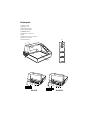
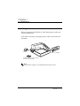
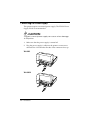
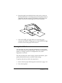
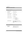
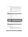
Printer parts
(1) Upper case
(2) Printer cover
(3) Operation panel
(4) Document table
(5) POWER switch
(6) Interface connector
(7) FG
(8) Drawer kick-out connector
(9) Power connector
(10) DIP switches
(3)
(1)
(2)
(5)
(4)
(10)
(6)
(7) (8) (9)
TM-U295
(10)
(6)
(7) (8) (9)
TM-U295P
All rights reserved. No part of this publication may be reproduced, stored in a
retrieval system, or transmitted in any form or by any means, mechanical,
photocopying, recording, or otherwise, without the prior written permission of Seiko
Epson Corporation. No patent liability is assumed with respect to the use of the
information contained herein. While every precaution has been taken in the
preparation of this book, Seiko Epson Corporation assumes no responsibility for
errors or omissions. Neither is any liability assumed for damages resulting from the
use of the information contained herein.
Neither Seiko Epson Corporation nor its affiliates shall be liable to the purchaser of
this product or third parties for damages, losses, costs, or expenses incurred by
purchaser or third parties as a result of: accident, misuse, or abuse of this product or
unauthorized modifications, repairs, or alterations to this product, or (excluding the
U.S.) failure to strictly comply with Seiko Epson Corporation’s operating and
maintenance instructions.
Seiko Epson Corporation shall not be liable against any damages or problems arising
from the use of any options or any consumable products other than those designated
as Original Epson Products or Epson Approved Products by Seiko Epson
Corporation.
EPSON and ESC/POS are registered trademarks of Seiko Epson Corporation.
NOTICE: The contents of this manual are subject to change without notice.
Copyright © 1997 by Seiko Epson Corporation, Nagano, Japan.
i
FCC CLASS A
FCC Compliance Statement
For American Users
This equipment has been tested and found to comply with the limits for a Class A
digital device, pursuant to Part 15 of the FCC Rules. These limits are designed to
provide reasonable protection against harmful interference when the equipment is
operated in a commercial environment.
This equipment generates, uses, and can radiate radio frequency energy and, if not
installed and used in accordance with the instruction manual, may cause harmful
interference to radio communications. Operation of this equipment in a residential
area is likely to cause harmful interference, in which case the user will be required to
correct the interference at his own expense.
WARNING
The connection of a non-shielded printer interface cable to this printer will invalidate
the FCC Verification of this device and may cause interference levels which exceed
the limits established by the FCC for this equipment.
You are cautioned that changes or modifications not expressly approved by the
party responsible for compliance could void your authority to operate the
equipment.
FOR CANADIAN USERS
This Class A digital apparatus meets all requirements of the Canadian InterferenceCausing Equipment Regulations.
Cet appareil numérique de la classe A respecte toutes les exigenves du Règlement
sur le matériel brouileur du Canada.
GEREÄUSCHPEGEL
Gemäß der Dritten Verordrung zum Gerätesicherheitsgecsetz
(Maschinenlärminformations- Verordnung-3. GSGV) ist der arbeitsplatzbezogene
Geräusch-Emissionswert kleiner als 70 dB(A) (basierend auf ISO 7779).
ii
DECLARATION of CONFORMITY for CE MARKING
Product Name:
Type Name:
Printer
M66SA
The printer conforms to the following Directives and Norms
Directive 89/336/EEC
EN 55022 (1986 and 1994) class B
EN 50082-1 (1992)
IEC 801-2 (1991)
IEC 801-3 (1984)
IEC 801-4 (1991)
Directive 90/384/EEC
EN45501: (1992)
iii
DECLARATION of CONFORMITY for CE MARKING
Product Name:
Type Name:
Printer
M117A
The printer conforms to the following Directives and Norms
Directive 89/336/EEC
EN 55022 (1986 and 1994) class B
EN 50082-1 (1992)
IEC 801-2 (1991)
IEC 801-3 (1984)
IEC 801-4 (1991)
Directive 90/384/EEC
EN45501: (1992)
iv
Introduction
The TM-U295 and TM-U295P are terminal slip printers which use a 7-pin shuttle dot
printing method, and provide the different modes, standard and page*.
The main features of the TM-U295 and TM-U295P printers are the following:
❏ Programmable page length
❏ Programmable print starting position
❏ Multiple character sizes (standard, double-width, double-height, and
quadruple)
❏ Character directions: 4
❏ International character set selection
❏ Forward and backward paper feeding
❏ Command protocol based on ESC/POS®, a widely used standard
❏ Programmable paper feed amount
❏ Paper eject function
❏ Top Of Form (TOF) and Bottom Of Form (BOF) sensors
❏ Data reception during printing (improved throughput and less waiting time for
the host computer)
❏ 512 byte printer buffer memory
❏ Compact, space efficient design
❏ Drawer kick-out function
❏ Automatic Status Back (ASB) function to automatically send printer status
changes.
* In page mode, the print data for each page is stored in a specified printing
area in memory. After all the data for a page has been stored, it is printed.
❏ Bidirectional parallel interface in accordance with the IEEE 1284 Nibble/Byte
Modes
Please be sure to read the instructions in this manual carefully before using your new
EPSON printer.
v
About This Manual
Setting Up and Using
❏ Chapter 1 contains information on setting the printer up and setting the DIP
switches.
❏ Chapter 2 contains information on using the printer.
❏ Chapter 3 contains troubleshooting information.
Reference
❏ Chapter 4 contains specifications
Notes, Cautions, and Warnings
Note:
Notes have important information and useful tips on the operation of your printer.
CAUTION:
Cautions must be observed to avoid minor injury to yourself or
damage to your equipment.
WARNING:
Warnings must be followed carefully to avoid serious bodily
injury.
vi
Contents
Introduction . . . . . . . . . . . . . . . . . . . . . . . . . . . . . . . . . . . . . . . . . . . . . . . . . . . . . . . . . . v
Chapter 1 Installation
Unpacking . . . . . . . . . . . . . . . . . . . . . . . . . . . . . . . . . . . . . . . . . . . . . . . . . . . . . . . . . . . . 1-1
Removing the Transportation Damper . . . . . . . . . . . . . . . . . . . . . . . . . . . . . . . . . . . . 1-2
Connecting the Printer to the Computer . . . . . . . . . . . . . . . . . . . . . . . . . . . . . . . . . . 1-2
TM-U295 . . . . . . . . . . . . . . . . . . . . . . . . . . . . . . . . . . . . . . . . . . . . . . . . . . . . . . . . . 1-3
TM-U295P . . . . . . . . . . . . . . . . . . . . . . . . . . . . . . . . . . . . . . . . . . . . . . . . . . . . . . . . 1-4
Connecting the Printer to the Drawer . . . . . . . . . . . . . . . . . . . . . . . . . . . . . . . . . . . . . 1-5
Grounding the Printer . . . . . . . . . . . . . . . . . . . . . . . . . . . . . . . . . . . . . . . . . . . . . . . . . . 1-7
Connecting the Power Supply . . . . . . . . . . . . . . . . . . . . . . . . . . . . . . . . . . . . . . . . . . . 1-8
Installing the Ribbon . . . . . . . . . . . . . . . . . . . . . . . . . . . . . . . . . . . . . . . . . . . . . . . . . . . 1-9
Inserting Paper . . . . . . . . . . . . . . . . . . . . . . . . . . . . . . . . . . . . . . . . . . . . . . . . . . . . . . . . 1-12
Running the Self Test . . . . . . . . . . . . . . . . . . . . . . . . . . . . . . . . . . . . . . . . . . . . . . . . . . . 1-13
Setting the DIP Switches . . . . . . . . . . . . . . . . . . . . . . . . . . . . . . . . . . . . . . . . . . . . . . . 1-14
TM-U295 . . . . . . . . . . . . . . . . . . . . . . . . . . . . . . . . . . . . . . . . . . . . . . . . . . . . . . . . . 1-16
TM-U295P . . . . . . . . . . . . . . . . . . . . . . . . . . . . . . . . . . . . . . . . . . . . . . . . . . . . . . . . 1-17
Chapter 2 Using the Printer
Buttons . . . . . . . . . . . . . . . . . . . . . . . . . . . . . . . . . . . . . . . . . . . . . . . . . . . . . . . . . . . . . . . 2-1
Indicator Lights . . . . . . . . . . . . . . . . . . . . . . . . . . . . . . . . . . . . . . . . . . . . . . . . . . . . . . . . 2-1
Replacing a Used Ribbon . . . . . . . . . . . . . . . . . . . . . . . . . . . . . . . . . . . . . . . . . . . . . . . 2-2
Chapter 3 Troubleshooting
Power problems . . . . . . . . . . . . . . . . . . . . . . . . . . . . . . . . . . . . . . . . . . . . . . . . . . . . . . . 3-1
Printing problems . . . . . . . . . . . . . . . . . . . . . . . . . . . . . . . . . . . . . . . . . . . . . . . . . . . . . . 3-1
Chapter 4 Reference Information
Printing Specifications . . . . . . . . . . . . . . . . . . . . . . . . . . . . . . . . . . . . . . . . . . . . . . . . . . 4-1
Character Specifications . . . . . . . . . . . . . . . . . . . . . . . . . . . . . . . . . . . . . . . . . . . . . . . . 4-1
Paper Specifications . . . . . . . . . . . . . . . . . . . . . . . . . . . . . . . . . . . . . . . . . . . . . . . . . . . . 4-3
Electrical Specifications . . . . . . . . . . . . . . . . . . . . . . . . . . . . . . . . . . . . . . . . . . . . . . . . . 4-6
EMI and Safety Standards . . . . . . . . . . . . . . . . . . . . . . . . . . . . . . . . . . . . . . . . . . . . . . . 4-7
Reliability . . . . . . . . . . . . . . . . . . . . . . . . . . . . . . . . . . . . . . . . . . . . . . . . . . . . . . . . . . . . . 4-7
Environmental Conditions . . . . . . . . . . . . . . . . . . . . . . . . . . . . . . . . . . . . . . . . . . . . . . 4-8
Interface Specifications . . . . . . . . . . . . . . . . . . . . . . . . . . . . . . . . . . . . . . . . . . . . . . . . . 4-8
vii
Chapter 5 Commands
Command Notation . . . . . . . . . . . . . . . . . . . . . . . . . . . . . . . . . . . . . . . . . . . . . . . . . . . . 5-1
Control Commands . . . . . . . . . . . . . . . . . . . . . . . . . . . . . . . . . . . . . . . . . . . . . . . . . . . . 5-2
viii
Chapter 1
Installation
Unpacking
When you unpack the TM-U295 or TM-U295P printer, make sure
you have these items.
If any item is missing or damaged, please contact your dealer for
assistance.
Damper
Ribbon cassette
Hexagonal lock screws (2 pcs)
(only for the TM-U295)
Note:
See the Note on page 1-3 for information about the screws.
Installation 1-1
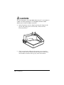
Removing the Transportation Damper
The printer is protected during shipping by a transportation
damper that must be removed before you turn on the printer.
1. Pull the damper out and remove the strip of tape from the top
of the printer, as shown below.
Note:
If you ever ship or store your printer, prepare it by performing these
steps: turn on the printer, press the RELEASE button, press the
FORWARD button, turn off the printer, and put the transportation
damper back where it was when you received the printer.
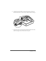
Connecting the Printer to the Computer
You need an appropriate interface cable to connect your computer
to the printer.
1-2 Installation
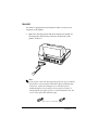
TM-U295
You need an appropriate serial interface cable to connect your
computer to the printer.
1. Make sure that the printer and the computer are turned off.
Then plug the cable into the connector on the back of the
printer, as shown.
Note:
Your printer comes with inch-type hexagonal lock screws installed.
If you plan to use an interface cable that requires millimeter-type
lock screws, replace the inch-type screws with the enclosed
millimeter-type screws by using a hex screwdriver (5 mm). To
distinguish the two types of screws, see the illustration below; the
screw on the right is the millimeter type.
TM-T85 / U/G / fig.2-07
95/03/06
Notch
(one or more lines)
Crestec
Installation 1-3
2. Connect the other end of the cable to the connector on your
computer.
TM-U295P
You need an appropriate parallel interface cable to connect your
computer to the printer.
1. Make sure that the printer and the computer are turned off.
Then plug the cable into the connector on the back of the
printer, as shown.
Note:
Squeeze the wire clips on the printer together until they lock in place
on both sides of the connector.
2. Connect the other end of the cable to the connector on your
computer.
1-4 Installation
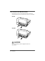
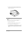
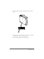
Connecting the Printer to the Drawer
Plug the drawer cable into the drawer kick-out connector on the
back of the printer next to the computer interface connector.
TM-U295
TM-U295P
CAUTION:
Do not connect a telephone line to the drawer kick out
connector.
Installation 1-5
Den Drucker an die Lade anschließen
Das Kabel der Lade an die Schnappsteckerbuchse (neben der
Schnittstellenbuchse) an der Hinterseite des Druckers anschließen.
TM-U295
TM-U295P
CAUTION:
Kein Telefonkabel an die Schnappsteckerbuchse
anschließen.
1-6 Installation
Grounding the Printer
You need an appropriate ground wire to ground your printer.
Recommended wire is described below.
Thickness of wire:
AWG 18 or equivalent
Diameter of terminal to be attached: 3.2
1. Make sure that the printer is turned off.
2. Connect the ground wire to the printer using the FG screw on
the back of the printer, as shown.
TM-U295
TM-U295P
Installation 1-7
Connecting the Power Supply
This printer requires an external power supply. The EPSON Power
Supply PS-150 is recommended.
CAUTION:
Using an incorrect power supply can cause serious damage
to the printer.
1. Make sure that the power supply is turned off.
2. Plug the power supply’s cable into the printer’s connector as
shown below. Note that the flat side of the connector faces up.
TM-U295
TM-U295P
1-8 Installation
3. Plug the power cord into an outlet.
Installing the Ribbon
Be sure to use a ribbon cassette that meets the printer’s
specifications. The EPSON ERC-27 is recommended.
Note:
For instructions on replacing a used ribbon, see Chapter 2.
1. Turn the printer on using the power switch on its left side.
2. Press the RELEASE button to turn the light on. This puts the
printer in the paper release mode.
3. Turn the printer off.
Installation 1-9
CAUTION:
Be sure to perform the steps above because it is necessary to
make sure that the printer is in the paper release mode
before you install the ribbon cassette.
4. Open the printer cover by slightly pressing the ridges on the
top left and pulling the cover forward, as shown in the
illustration below.
5. Check to see that the ribbon in the cassette is not creased or
twisted. Then turn the feed knob in the direction of the arrow
on the ribbon cassette to take up any slack in the ribbon.
1-10 Installation
6. Carefully insert the ribbon cassette in the printer as shown in
the illustration below. Notice exactly where the ribbon must go.
7. Then push firmly on the right side and then the left side of the
ribbon cartridge until each side clicks into place.
Installation 1-11
8. To put the cover back on the printer, first align the left and
insert the tab on the top; then press the bottom until it clicks
into place, as shown below.
Inserting Paper
Note:
Do not use wrinkled or curled paper. For full information and
specifications on the paper you can use, see Chapter 4.
To insert paper, follow these steps:
1. Make sure that a ribbon cassette is installed in the printer.
2. Turn on the printer. The POWER light comes on.
3. Press the RELEASE button. The RELEASE light comes on, which
indicates that the printer is in the paper release mode. In this
mode, the printer can accept paper and paper can be removed
from it.
1-12 Installation
4. Insert the paper from either the front or the side, as shown in
the illustration below. Insert the paper into the printer until it is
stopped by the form stopper. The markings on the side of the
printer can also be used to judge how far to insert paper.
5. Check the PAPER OUT light. When you insert the paper
correctly, the PAPER OUT light goes out. If the PAPER OUT light
is still on, remove the paper and re-insert it.
Running the Self Test
Any time that you want to check the performance of your printer
you can run the self test described below. This shows whether your
printer is working correctly. It is independent of any other
equipment or software.
The self test checks the control circuits, printer mechanisms, print
quality, RAM, ROM version, and DIP switch settings.
To perform the self test, follow the steps below:
1. Insert a sheet of paper following the instructions on page 1-12.
2. Turn off the printer.
Installation 1-13
3. While holding down the RELEASE button, turn the printer back
on.
4. Remove your finger from the RELEASE button. The printer
prints the current printer settings and then eject the paper.
5. Press the RELEASE button to eject the paper completely and
insert new paper to begin the second part of the test.
After the printer prints a pattern, it prints the following message:
***completed***
The printer ejects the paper; then enters the normal mode.
Setting the DIP Switches
You can change several interface settings by changing the DIP
switch settings. If you need to change any of these settings, follow
the steps below:
1. Make sure that the printer is off.
1-14 Installation
2. Turn the printer over and locate the DIP switches, as shown
below.
3. Notice that ON is marked on the set of switches. Use tweezers
or another narrow tool to move the switches.
4. Use the following tables to set the DIP switches.
Installation 1-15
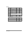
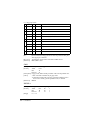
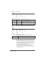
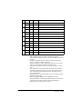
TM-U295
Switch
Function
ON
OFF
1
Data reception error
Ignored
Prints”?”
2
Receive buffer capacity
35 bytes
512 bytes
3
Handshaking
XON/XOFF
DTR/DSR
4
Word length
7 bits
8 bits
5
Parity check
Yes
No
6
Parity selection
Even
Odd
7
See Transmission Speeds table below.
8
9
Pin 6 reset signal
Used
Not used
10
Pin 25 reset signal
Used
Not used
Transmission Speeds
Speed in Bits per Second
SW 7
SW 8
1200
ON
ON
2400
OFF
ON
4800
ON
OFF
9600
OFF
OFF
1-16 Installation
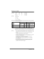
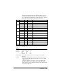
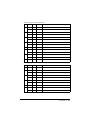
TM-U295P
Switch
Function
ON
OFF
1
Auto-line feed
Normally
enabled
Normally
disabled
2
Receive buffer capacity
35 bytes
512 bytes
3
Undefined
4
Undefined
5
Undefined
6
Undefined
7
Undefined
8
Undefined
9
Undefined
10
Reserved. Setting must
not be changed
Note:
If you change any DIP switch settings while the printer is turned
on, the new settings will not take effect until you turn the printer off
and back on or reset it.
Installation 1-17
Chapter 2
Using the Printer
The control panel has three buttons and three lights.
Buttons
All three of these buttons can be disabled or enabled by the ESC c 5
command.
RELEASE
Pressing this button moves the rollers so that paper can be inserted
or removed.
REVERSE
Feeds the paper backward based on the line feed amount set by
ESC 2 and ESC 3.
FORWARD
Feeds the paper forward based on the line feed amount set by
ESC 2 and ESC 3.
You can also use the RELEASE button to start a self test.
See Chapter 1 for details.
Indicator Lights
POWER
This light is on whenever power is supplied to the printer.
Using the Printer 2-1
RELEASE
This light is on when the printer is in the paper release mode and it
is off when the printer is in the clamp mode. Paper can be inserted
only when the printer is in the paper release mode.
This light blinks to indicate an error condition in the following
cases:
❏ Paper jam
❏ Home position error
❏ Timing error
❏ Drive circuit error
❏ Power supply voltage error
If this light blinks, turn off the printer, make sure that no paper is
jammed in it, and then turn it back on. If the light is still blinking,
contact a qualified service person.
PAPER OUT
This light is on when paper is not inserted or is not inserted
correctly.
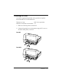
Replacing a Used Ribbon
When your printing is not dark enough, it is time to replace the
ribbon.
First follow steps 1 through 4 in the “Installing the Ribbon” in
Chapter 1.
2-2 Using the Printer
Then remove the used ribbon by grasping the handle and pulling
straight out, as shown by the arrow in the illustration below.
Then follow the rest of the steps in “Installing the Ribbon” in
Chapter 1.
Using the Printer 2-3
Chapter 3
Troubleshooting
This chapter gives the solutions to some printer problems.
Power problems
The POWER light does not come on.
Make sure that the power supply cables are correctly plugged into
the printer, the power unit, and to the power outlet.
Make sure that power is supplied to the power outlet. If the outlet
is controlled by a switch or timer, use another outlet.
Printing problems
The PAPER OUT light is on and nothing is printed.
If the PAPER OUT light is on, the paper is not inserted or is not
inserted correctly.
The RELEASE light is flashing and nothing is printed.
This indicates an error condition. Turn off the printer, make sure
that no paper is jammed in it, and then turn it back on. If the
RELEASE light is still flashing, contact a qualified service person.
Troubleshooting 3-1
Chapter 4
Reference Information
Printing Specifications
Printing Method:
Impact dot matrix
Head Wires
7-pin shuttle type
Printing Direction:
Unidirectional
Lines per second
5 x 7 font: 1.9 to 2.3
7 x 7 font: 1.9 to 2.3
Characters per line
5 x 7 font: 35
7 x 7 font : 42
Characters per inch:
5 x 7 font: ANK: 0.63
Graphics: 0.315
7 x 7 font: ANK: 0.63
Graphics: 0.315
Paper feed speed:
Approximately 12.5 lines (52.5 mm
(2.10”))/second
(When the ESC d and FF commands are
used.)
Character Specifications
Number of
characters
Alphanumeric characters: 95
Extended graphics: 128 x 3
International characters: 32
Reference Information 4-1
Character structure:
5 x 7 with 1-dot spacing (normal dot)
7 x 7 with 3-dot spacing (half dot)
Character size:
5 x 7 font:
ANK: 1.6 mm (.063”) x 2.9 mm (.114”)
Graphics: 1.9 mm (.075”) x 2.9 mm
(.114”)
7 x 7 font:
ANK: 1.3 mm (.051”) x 2.9 mm (.114”)
Graphics: 1.6 mm (.063”) x 2.9 mm
(.114”)
4-2 Reference Information
Paper Specifications
Paper type:
Normal (high quality), pressure
sensitive, and carbon copy papers
Total thickness:
Single-play paper: 0.09 to 0.25 mm
(.0035 to .0098”)
Copy paper: 0.09 to 0.35 mm (.0035
to .0138”)
Paper size:
80 mm (W) × 69 mm (L) to 182 mm
(W) × 257 mm (L) (3.15” × 2.72” to
7.17” × 10.12”) Up to the European
B5 size.
Copy capability and
paper thickness:
No copies
(singleply):
0.09 to 0.25 mm
(.0035 to .0098”)
(135 kg paper or
equivalent)
Combination of
normal
paper and
pressure
sensitive
paper:
3 sheets
maximum (1
original and 2
copies) (0.09 to
0.35 mm (.0035 to
.0138”))
Backing paper:
0.07 to 0.20 mm
(.0028 to .0079”)
Copy and original
paper:
0.04 to 0.07 mm
(.0016 to .0028”)
Carbon copy
paper:
Approximately
0.035 mm (.0014”)
Reference Information 4-3
Copy capability and
ambient
temperature for
printing:
Copying capability is influenced by
the ambient temperature. Printing
must be performed under the
conditions, described in a Table
below:
Relationship between ambient temperature and
number of copies
Number of copies
Ambient temperature (print mode)
Original + 1 to 2 copies
5° to 40°C (41° to 104°F)
Notes on slip paper
❏ Slip paper should be flat, without curls, wrinkles, or camber,
especially at the paper edges. Otherwise, the paper may
become ink stained.
❏ When using multiply-ply carbon copy paper, it should be flat
and the glue area should be as small as possible.
❏ Glue area should be located at the top or left edge of the slip
paper.
❏ Since TOF and BOF sensors are optical sensors, paper having
holes at the sensor positions or translucent paper should not be
used normallly. When using these papers, be sure to disable the
paper sensors by ESC c 4.
❏ When using slip paper of 80 mm (3.15”) long or less, load the
paper so that it is fed straight.
❏ Use thinner paper (N30 or equivalent) between the top and
bottom sheets of multi-ply paper. If thick paper is used, the
copy capability is lowered.
4-4 Reference Information
Printing position
NOTE 1. Mechanical form stopper
Forward paper feed
5 (.20")
65.84 (2.59")
10 (.39")
First printing position
Paper feed roller
Last printing position
NOTE 2. BOF sensor (fixed)
27.3 (1.07")
Reverse paper feed
Printing position at minimum top margin
26.5 (1.04")
2.3 (.09")
NOTE 3. 5.3 (.21")
NOTE 2. TOF sensor (fixed)
NOTE 4. 13.8 (.54")
Adjustable
NOTE 5. 15.5 (.61")
12.5 (.49")
12.5 (.49")
Notes
1. The mechanical form stopper is adjustable in the range 26.5 to
36.5 mm (1.04 to 1.44”).
2. The TOF and BOF sensors are fixed and cannot be adjusted.
3. After slip paper is set at the mechanical form stopper, the top
margin can be shortened up to 21.2 mm (.83”) by feeding the
paper backwards (ejection feeding).
4. When ejection feeding is not performed after printing, printing
can be performed up to the position at which the paper edge is
no longer held by the paper feed roller (13.8 mm (.54”) from the
paper edge).
5. When ejection feeding is performed after printing, the paper
can be fed forward up to 11.8 mm (.46”) (28 dots) after the
bottom edge is detected.
Reference Information 4-5
Electrical Specifications
Supply voltage:
+24 VDC ± 10%
Current consumption:
Operating
(except for
drawer kickout):
Mean - approx.
600 mA at 24
VDC (full-column
printing and data
transmission of
ANK characters)
Peak - approx.
5.5 A at 24 VDC
(full-column
printing and data
transmission of
ANK characters)
Standby: approx.
100 mA (at 24
VDC, 25°C (77°F)
4-6 Reference Information
EMI and Safety Standards
EMI standards
(measured when
using the printer with
the Epson PS-150):
FCC:
Class A
Safety standards:
UL1950-2TH-D3 (Recognized
component)
CE marking:
CSA950-D3 (Recognized component)
EN60950 (IEC950 2TH)
Reliability
Life:
3,000,000 lines
❑ End of Life is defined as the point
at which the printer reaches the
beginning of the Wearout Period.
MTBF:
180,000 hours
❑ Failure is defined as Random
Failure occurring at the time of the
Random Failure Period.
MCBF:
7,000,000 lines
❑ This is an average failure interval
based on failures relating to
wearout and random failures up to
the life of 3 million lines.
Reference Information 4-7
Environmental Conditions
Temperature:
Humidity:
Operating:
5° to 40°C (41° to
104°F)
Storage:
-10° to 50°C (14°
to 122°F) (except
for ribbon and
paper)
Operating:
30 to 85% (with
no condensation)
Storage:
30 to 90% (with
no condensation,
except for ribbon
and paper)
Interface Specifications
Serial interface:
RS-232 compatible
Parallel interface:
IEEE 1284 compatible (Nibble/Byte
Modes)
Note:
The interface is a factory installed option. One of the interfaces
(serial or parallel) is already installed.
Note:
Refer to the EPSON TM-U295/U295P Specification for details.
4-8 Reference Information
Chapter 5
Commands
Command Notation
[Name]
[Format]
The name of the command.
The code sequence.
ASCII indicates the ASCII equivalents.
Hex indicates the hexadecimal equivalents.
Decimal indicates the decimal equivalents.
[ ]k indicates the contents of the [ ] should be repeated k times.
[Range]
Gives the allowable ranges for the arguments.
[Description] Describes the function of the command.
[Notes]
Provides important information on setting and using the printer
command, if necessary.
[Default]
Gives the default values, if any, for the command parameters.
[Reference] Lists related commands.
[Example]
Provides examples using the command.
The numbers denoted by < >H are hexadecimal.
The numbers denoted by < >B are binary.
The numbers denoted by < > are decimal.
NOTE:
The phrase "beginning of a line" in command descriptions assumes
that the following condition has been met:
• Print data, including spaces skipped by HT, is not in the current
print buffer.
Commands 5-1
Control Commands
HT
[Name]
[Format]
Horizontal tab
ASCII
HT
Hex
09
Decimal
9
[Description] Moves the print position to the next horizontal tab position.
[Notes]
• Horizontal tab positions are set with ESC D.
• Ignored unless the next horizontal tab position has been set.
• The default tab positions are at intervals of 8 characters in the
5 x 7 font 9th column, 17th column, 25th column,. . . ).
[Reference] ESC D
LF
[Name]
[Format]
Print and line feed
ASCII
LF
Hex
0A
Decimal
10
[Description] Prints the data in the print buffer and feeds one line based on the
current line spacing.
[Note]
This command sets the print position to the beginning of the line.
[Reference] ESC 2, ESC 3
FF
➀Print and eject sheet (in standard mode)
➁Print and return to standard mode (in page mode)
[Format]
ASCII
FF
Hex
0C
Decimal
12
This command functions differently depending on the printer mode selected.
➀When standard mode is selected:
[Description] Prints the data in print buffer and ejects the sheet.
[Notes]
• When the eject length has been set by ESC C, the printer ejects the
sheet based on the current eject length. Otherwise, the printer
ejects the sheet completely. If a paper out is detected during
ejection, the printer stops ejecting the sheet even if the specified
amount of paper has not been ejected.
• The ejecting direction is specified by ESC F.
[Reference] ESC F, ESC C
➁When page mode is selected:
[Name]
5-2 Commands
[Description] Prints the data in the print buffer and returns to standard mode.
[Notes]
• The buffer data is deleted after being printed.
• The printer does not execute paper ejection.
• This command sets the print position to the beginning of the line.
[Reference]
ESC L
CR
[Name]
[Format]
Print and carriage return
ASCII
CR
Hex
0D
Decimal
13
[Description] When auto-line feed is enabled, this command functions in the same
way as LF. When auto-line feed is disabled, this command is ignored.
[Notes]
• This command sets the print position to the beginning of the line.
• This command is available only with a parallel interface and is
ignored with a serial interface.
DLE EOT n
[Name]
[Format]
Real-time status transmission
n
ASCII
DLE
EOT
n
Hex
10
04
n
Decimal
16
4
[Range]
1≤ n ≤ 3, n = 5
[Description] Transmits the selected printer status specified by n in real time,
according to the following parameters:
n = 1: Transmit printer status
n = 2: Transmit off-line status
n = 3: Transmit error status
n = 5: Transmit slip paper status
[Notes]
• The printer executes this command upon receiving it.
• When transmitting status, the printer transmits only 1 byte
without confirming the condition of the DSR signal.
• With the serial interface model, this command is executed even in
off-line or receive buffer-full state. However, with the parallel
interface model, this command is not executed in off-line or
receive buffer-full state because the printer is busy and unable to
receive this command from the host.
• The status is transmitted whenever the data sequence of
<10>H<04>H<n> (1 ≤ n ≤ 3, n = 5) is received even if it appears as
part of another command. For example,
In ESC ✻ m n L n H [d] n L+256✕n H, d1=<10>H, d2=<04>H,
d3=<1>H
Commands 5-3
• This command should not be used within the data sequence of
another command that consists of 2 or more bytes. For example,
If you attempt to transmit ESC 3 n to the printer, but DTR (DSR
for the host computer) goes to MARK before n is transmitted
and then DLE EOT 3 interrupts before n is received, the code
<10>H for DLE EOT 3 is processed as the code for ESC 3
<10>H.
• When Auto Status Back (ASB) is enabled using the GS a
command, the status transmitted by the DLE EOT command and
the ASB status must be differentiated.
• If the n is out of the specified range, the printer ignores this
command.
n = 1: Printer status
Bit
Off/On
Hex
Decimal
Function
0
Off
00
0
Not used. Fixed to Off.
1
On
02
2
Not used. Fixed to On.
Off
00
0
Drawer kick-out signal is LOW (connector pin 3)
On
04
4
Drawer kick-out signal is HIGH (connector pin 3)
Off
00
0
On-line.
On
08
8
Off-line.
On
10
16
Not used. Fixed to On.
Off
00
0
Undefined.
On
20
32
Undefined.
Off
00
0
Undefined.
On
40
64
Undefined.
Off
00
0
Not used. Fixed to Off.
2
3
4
5
6
7
n = 2: Off-line status
Bit
Off/On
Hex
Decimal
Function
0
Off
00
0
Not used. Fixed to Off.
1
On
02
2
Not used. Fixed to On.
Off
00
0
Undefined.
On
04
4
Undefined.
2
5-4 Commands
Bit
Off/On
Hex
Decimal
Function
Off
00
0
Paper is not being fed by using the paper feed
button.
On
08
8
Paper is being fed by the paper feed button.
On
10
16
Not used. Fixed to On.
Off
00
0
No paper-end stop.
On
20
32
Printing stops due to paper end.
Off
00
0
No error.
On
40
64
Error occurs.
Off
00
0
Not used. Fixed to Off.
3
4
5
6
7
Bit 5:
On (printing stops due to paper-end) indicates printing stops as a
result of the paper state and TOF or BOF sensor selected by ESC c 4.
n = 3: Error status
Bit
Off/On
Hex
Decimal
Function
0
Off
00
0
Not used. Fixed to Off.
1
On
02
2
Not used.Fixed to On.
Off
00
0
Undefined.
On
04
4
Undefined.
Off
00
0
Undefined.
On
08
8
Undefined.
On
10
16
Not used. Fixed to On.
Off
00
0
No unrecoverable error.
On
20
32
Unrecoverable error occurred.
Off
00
0
Undefined.
On
40
64
Undefined.
Off
00
0
Not used. Fixed to Off.
2
3
4
5
6
7
Commands 5-5
n = 5: Slip paper status
Bit
Off/On
Hex
Decimal
Function
0
Off
00
0
Not used. Fixed to Off.
1
On
02
2
Not used. Fixed to Off.
2
Off
00
0
Slip paper selected.
Off
00
0
Does not wait for slip paper insertion.
On
08
8
Waits for slip paper insertion.
On
10
16
Not used. Fixed to On.
Off
00
0
Slip is detected by the BOF sensor.
On
20
32
Slip is not detected by the BOF sensor.
Off
00
0
Slip is not detected by the TOF sensor.
On
40
64
Slip is detected by the TOF sensor.
Off
00
0
Not used. Fixed to Off.
3
4
5
6
7
Bit 3:
Bit 5 and 6:
[Reference]
Becomes Off (not waiting) just before actual slip selection takes place
after slip paper is detected
Transmits the current status of the TOF and BOF sensors.
ESC u, ESC v, GS a
CAN
[Name]
[Format]
Cancel print data in page mode
ASCII
CAN
Hex
18
Decimal
24
[Description] In page mode, deletes all the print data in the current printable area.
[Notes]
• This command is enabled only in page mode.
• If data that existed in the previously specified printable area also
exists in the currently specified printable area, it is deleted.
[Reference] ESC W
ESC SP n
[Name]
[Format]
[Range]
5-6 Commands
Set right-side character spacing
n
ASCII
ESC
SP
n
Hex
1B
20
n
Decimal
27
32
0 ≤ n ≤ 32
[Description] Sets the character spacing for the right side of the character.
[Notes]
• The right-side character spacing for double-width mode is twice
the normal value.
• The character spacing is set in increment of half dot.
• In page mode, the actual dot positions shift by half dot.
• This command sets values independently in standard mode and
in page mode.
n =0
[Default]
ESC ! n
[Name]
[Format]
Select print mode(s)
n
ASCII
ESC
!
n
Hex
1B
21
n
Decimal
27
33
[Range]
0 ≤ n ≤ 255
[Description] Selects print mode(s) using n as follows:
Bit
Off/On
Hex
Decimal
Function
Off
00
0
Character font 5 ✕ 7 selected.
On
01
1
Character font 7 ✕ 7 selected.
Off
00
0
Undefined.
On
02
2
Undefined.
Off
00
0
Undefined
On
04
4
Undefined.
Off
00
0
Undefined.
On
08
8
Undefined.
Off
00
0
Double-height mode not selected.
On
10
16
Double-height mode selected.
Off
00
0
Double-width mode not selected.
On
20
32
Double-width mode selected.
Off
00
0
Undefined.
On
40
64
Undefined.
Off
00
0
Underline mode not selected.
On
80
128
Underline mode selected.
0
1
2
3
4
5
6
7
Commands 5-7
[Notes]
[Default]
• The printer can underline all characters (including the right-side
character spacing), but cannot underline the space set by an HT.
• When both double-height and double-width modes are selected,
quadruple size characters are printed.
• Only setting of underline mode specification have effect in page
mode.
• Only setting of 7 × 7 font specification have effect in page mode.
n=0
ESC % n
[Name]
[Format]
Select/cancel user-defined character set
n
ASCII
ESC
%
n
Hex
1B
25
n
Decimal
27
37
[Range]
0 ≤ n ≤ 255
[Description] Selects or cancels the user-defined character set.
When the Least Significant Bit (LSB) is 0, the user-defined character
set is cancelled.
When the LSB is 1, the user-defined character set is selected.
[Notes]
• When the user-defined character set is cancelled, the internal
character set is automatically selected.
n=0
[Default]
[Reference] ESC &
ESC & y c1 c2 [X [d] y ✕ x] c2-c1+1
[Name]
[Format]
Define user-defined characters
y c1 c2 [x [d] y ✕ x] c2 - c1 + 1
ASCII
ESC
&
y c1 c2 [x [d] y ✕ x] c2 - c1 + 1
Hex
1B
26
y c1 c2 [x [d] y ✕ x] c2 - c1 + 1
Decimal
27
38
y=1
[Range]
32 ≤ c1 ≤ c2 ≤ 126
0 ≤ x ≤ 6 (5 ✕ 7 font)
0 ≤ x ≤ 10 (7 ✕ 7 font)
0 ≤ d1 ... dy ✕ x ≤ 255
[Description] Defines user-defined characters.
• The y specifies the number of bytes in the vertical direction.
• c1 specifies the beginning character code for the definition, and c2
specifies the final code. When only one character is desired, use c1
= c2.
• The allowable character code range is from decimal code 32 to 126.
• x specifies the number of dots in the horizontal direction.
5-8 Commands
[Notes]
• d is the dot data for the characters. The dot pattern is in the
horizontal direction from the left side. Any remaining dots on
right side are blank.
• The data to define a user-defined character is (y × x) bytes.
• Set a corresponding bit to 1 to print a dot or to 0 to not print a dot.
• It is possible to define multiple characters for consecutive
character codes.
• After user-defined characters are defined, they are available until
another definition is made; ESC @ is executed; the printer is reset;
or the power is turned off.
• If the values of y, c1, c2, or x are out of the specified range, the
printer ignores the command and processes the following data as
normal data.
• In 7 × 7 font, horizontally adjacent dots cannot be printed. Define
the character so that it does not include horizontally adjacent dots.
The internal character set
ESC %
[Default]
[Reference]
[Example]
•5 × 7 font when the dot pattern for code 32 (20H) is defined as shown below:
p1 p2 p3 p4 p5 p6
MSB
LSB
ASCII code ESC & y c1 c2 x p1 p2 p3 p4 p5
Hex code
1B 26 01 20 20 05 3E 48 88 48 3E
Commands 5-9
•7 × 7 font when the dot pattern for code 32 (20H) is defined as shown below:
p1 p2 p3 p4 p5 p6 p7 p8 p9 p10
MSB
LSB
ASCII code ESC & y c1 c2 x p1 p2 p3 p4 p5 p6 p7
Hex code
1B 25 01 20 20 07 1E 20 48 80 48 20 1E
5-10 Commands
ESC ✽ m nL n H [d]k
[Name]
[Format]
Select bit-image mode
nL nH [d]k
✽
ASCII
ESC
nL nH [d]k
Hex
1B
2A
nL nH [d]k
Decimal
27
42
m = 0, 1
[Range]
0 ≤ nL ≤ 255
0 ≤ nH ≤ 3
0 ≤ d ≤ 255
k = nL + nH x 255
[Description] Selects a bit-image mode using m for the number of dots specified by
nL and nH, as follows:
Vertical direction
Horizontal direction
m
Mode
The number
of dots
Dot
density
Dot
density
Maximum
number of dots
0
8-dot single-density
8
60 DPI
80 DPI
210
1
8-dot double-density
8
60 DPI
160 DPI
420
[Notes]
The number of dots in the horizontal direction depends on the
printing area and the printing direction specified by ESC W and ESC
T.
• The nL and nH indicate the number of dots of the bit image in the
horizontal direction. The number of dots is calculated by nL + nH
✕ 256.
• If the bit-image data input exceeds the number of dots to be
printed on a line, the excess data is ignored.
• d indicates the bit-image data. Set a corresponding bit to 1 to print
a dot or to 0 to not print a dot.
• If the values of m and nH are out of the specified range, the
following data is processed as normal data.
• After printing a bit image, the printer returns to normal data
processing mode.
• In page mode, double density bit image data is not available.
• The relationship between the image data and the dots to be
printed is shown on the next page.
Commands 5-11
• The relationship between the image data and the dots to be printed is as follows:
7 6 5 4
3 2
1 0
Print data
Top
Bottom
Bit image data
ESC 2
[Name]
[Format]
Select 1/6-inch line spacing
ASCII
ESC
2
Hex
1B
32
Decimal
27
50
[Description] Selects 1/6-inch line spacing.
[Note]
The line spacing can be set independently in standard mode and in
page mode.
[Reference] ESC 3
ESC 3 n
[Name]
[Format]
Set line spacing
n
ASCII
ESC
3
n
Hex
1B
33
n
Decimal
27
51
[Range]
0 ≤ n ≤ 255
[Description] Sets the line spacing to n/60 inches.
[Notes]
• This command sets values independently in standard mode and
in page mode.
n = 10 (1/6 inch)
[Default]
[Reference] ESC 2
ESC = n
[Name]
[Format]
5-12 Commands
Set device
ASCII
ESC
=
n
n
Hex
1B
3D
n
Decimal
27
61
[Range]
0≤n≤3
[Description] Selects device to which host computer sends data, using n as follows:
Bit
Off/On
Hex
Decimal
Function
Off
00
0
Printer disabled.
On
01
1
Printer enabled.
Off
00
0
Undefined.
On
02
2
Undefined.
Off
00
0
Undefined.
On
04
4
Undefined.
Off
00
0
Undefined.
On
08
8
Undefined.
Off
00
0
Undefined.
On
10
16
Undefined.
Off
00
0
Undefined.
On
20
32
Undefined.
Off
00
0
Undefined.
On
40
64
Undefined.
Off
00
0
Undefined.
On
80
128
Undefined.
0
1
2
3
4
5
6
7
[Notes]
[Default]
• When the printer is not selected, the printer ignores all received
data until it is selected by this command.
• Even if the printer is disabled, it may go off-line due to printer
operation.
n=1
ESC @
[Name]
[Format]
Initialize printer
ASCII
ESC
@
Hex
1B
40
Decimal
27
64
[Description] Clears the data in the print buffer and resets the printer mode to the
mode that was in effect when the power was turned on.
Commands 5-13
17, 25,...) for the 12 ✕ 24 font.
[Reference]HT
[Notes]
• The DIP switch settings are not checked again.
• The data in the receive buffer is not cleared.
• The macro definition is not cleared.
ESC C n
[Name]
[Format]
Set cut sheet eject length
n
ASCII
ESC
C
n
Hex
1B
43
n
Decimal
27
67
[Range]
0 ≤ n ≤ 127
[Description] Sets the eject length for a cut sheet to n lines.
[Notes]
• When n = 0, no eject length is set.
• The previously specified eject length does not change, even if the
line spacing changes.
• This command is available only when FF is executed.
[Default]
n=0
[Reference] FF
ESC D [n] k NUL
[Name]
[Format]
Set horizontal tab positions
ASCII
ESC
D
[n] k NUL
Hex
1B
44
[n] k 00
Decimal
27
68
[n] k 0
[Range]
1 ≤ n ≤ 255
0 ≤ k ≤ 32
[Description] Sets horizontal tab positions.
• n specifies the column number for setting a horizontal tab position
from the beginning of the line.
• This command cancels the previous horizontal tab settings.
• n = column number to be set - 1. When setting n = 8, the print
position is moved to column 9 by sending HT.
• k indicates the total number of horizontal tab positions to be set.
• The horizontal tab position is stored as an absolute value of
[character width ✕ n] measured from the beginning of the line. The
character width includes the right-side character spacing, and
double-width characters are set with twice the width of normal
characters. Also, when character is enlarged in the horizontal
direction in page mode, the horizontal position is set as the same
way as in standard mode.
• Transmit [n]k in ascending order and place a NUL code 0 at the
end.
• ESC D NUL cancels all horizontal tab positions. An HT received
after clearing tabs is ignored.
5-14 Commands
[Notes]
[Default]
• Up to 32 tab positions (k = 32) can be set. Data exceeding 32 tab
positions is processed as normal data.
• When [n]k is less than or equal to the preceding value [n]k-1, tab
setting is finished and the following data is processed as normal
data.
• When [n]k exceeds the number of characters printable on one line,
the tab position set is equal to the maximum printable column
plus 1.
• The previously specified horizontal tab positions do not change,
even if the character width changes.
• The right-side spacing is set independently in standard and page
modes. The horizontal tab setting is set by using amount of the
right-side spacing of the mode used.
The default tab positions are at intervals of 8 characters (columns 9,
17, 25,...) for the default character font.
ESC F n
[Name]
[Format]
Set/cancel cut sheet reverse eject
n
ASCII
ESC
F
n
Hex
1B
46
n
Decimal
27
70
[Range]
0 ≤ n ≤ 255
[Description] Sets or cancels the cut sheet reverse eject specified by FF.
• When the LSB of n is 0, reverse eject is canceled and forwqrd eject
is set.
• When the LSB of n is 1, reverse eject is set.
[Note]
When n cancels reverse eject, this command sets forward ejection
automatically.
n=0
[Default]
[Reference] FF
ESC J n
[Name]
[Format]
Print and feed paper
n
ASCII
ESC
J
n
Hex
1B
4A
n
Decimal
27
74
[Range]
0 ≤ n ≤ 255
[Description] Prints the data in the print buffer and feeds the paper by n/60
inches.
[Note]
Sets the print position to the beginning of the line.
ESC K n
[Name]
print and revers feed
Commands 5-15
n
ASCII
ESC
K
n
Hex
1B
4B
n
Decimal
27
75
[Range]
0 ≤ n ≤ 255
[Description] Prints the data in the print buffer and feeds the paper by n/60 inches
in the reverse direction.
[Notes]
• This command is available only in standard mode.
• The setting values do not remain.
• After printing is completed, this command sets the print position
to the beginning of the line.
[Format]
ESC L
[Name]
[Format]
Select page mode
ASCII
ESC
L
Hex
1B
4C
Decimal
27
76
[Description] Switches from standard mode to page mode.
[Notes]
• This command is enabled only when input at the beginning of a
line.
• This command is available only in standard mode.
• After printing by FF is completed, the printer returns to standard
mode.
• This command sets the position where data is buffered to the
position specified by ESC T within the printable area defined by
ESC W.
• In page mode, the printer buffer receives data in the printable area
specified by ESC W and prints the data collectively upon receipt
of FF command. The print and line feed commands, such as LF,
ESC J, ESC K, ESC d, and ESC e, only move the print start
position from which subsequent data is buffered and do not
perform actual printing.
• In page mode, the printer porcesses data referring to normal dot.
Therefore, be careful when using half dot in standard mode.
• Only character fonts with normal dot configuration are available.
• This command switches the settings for the following commands
(in which the values can be set independently in standard mode
and page mode) to those for page mode:
Set character spacing: ESC SP
Select 1/6-inch line spacing: ESC 2
Set line spacing: ESC 3
• In page mode, the following commands are ignored.
Print and reverse feed n lines: ESC e
Print and reverse feed: ESC K
5-16 Commands
[Default]
[Reference]
Double-density bit image: ESC ✻
Paper release: ESC q
• The following commands are settable but do not have any effect
in page mode.
Upside-down character mode: ESC {
7 × 7 font and underline mode specification and cancel: ESC !
• This command is effective only in standard mode.
• ESC @ command returns the printer to standard mode without
printing any data.
Standard mode
FF
ESC R n
[Name]
[Format]
Select an international character set
n
ASCII
ESC
R
n
Hex
1B
52
n
Decimal
27
82
[Range]
0 ≤ n ≤ 10
[Description] Selects an international character set n from the following table:
n
Character set
0
U.S.A.
1
France
2
Germany
3
U.K.
4
Denmark I
5
Sweden
6
Italy
7
Spain
8
Japan
9
Norway
10
Denmark II
[Note]
[Default]
[Reference]
If the value of n is out of specified range, printer ignores the
command.
n=0
Character Code Tables
Commands 5-17
ESC T n
[Name]
[Format]
Select print direction in page mode
n
ASCII
ESC
T
n
Hex
1B
54
n
Decimal
27
84
[Range]
0≤n≤3
48 ≤ n ≤ 51
[Description] Selects the print direction and starting position in page mode.
n specifies the print direction and starting position as follows:
Starting Position
0, 48
Left to right
Upper left
(A in the figure)
1, 49
Bottom to top
Lower left
(B in the figure)
2, 50
Right to left
Lower right
(C in the figure)
3, 51
Top to bottom
Upper right
(D in the figure)
[Notes]
[Default]
D
A
B
Printing area
C
Print Direction
Paper feed direction
n
• When the printing direction is changed, the printing direction and
print starting position for the data following are those specified by
n.
• Only setting of this command is effective in standard mode.
• If n is out of the specified range, this command is ignored.
n=0
ESC W xL xH yL yH dxL dxH dyL dyH
[Name]
[Format]
Set printing area in page mode
xL xH yL yH dxL dxH dyL dyH
ASC II
ESC
W
xL xH yL yH dxL dxH dyL dyH
Hex
1B
57
xL xH yL yH dxL dxH dyL dyH
Decimal
27
87
[Range]
0 ≤ xL≤ 255, xH=0, 0 ≤ yL≤ 255, 0 ≤ yH≤ 1, 0 ≤ dxL≤ 255, dxH=0, 0 ≤
dyL≤ 255, 0 ≤ dyH≤ 1 (Except for dxL=dxH=0 or dyL=dyH=0)
[Description] Sets the position and the size of the printing area.
• When the horizontal print start position, vertical print start
position, horizontal length, and vertical length are defined as x0,
y0, dx (dot), dy (dot), respectively.
Each setting for the printable area is calculated as follows:
x0 = [(xL + xH ✕ 256)]
y0 = [(yL + yH ✕ 256)]
5-18 Commands
dx = [dxL + dxH ✕ 256]
dy = [dyL + dyH ✕ 256]
The printable area is set as shown in the figure below.
(0, 0)
Printable area of the paper
(x0, y0)
dy
dx
Printing area
(x0+dx-1,
y0+dy-1)
(209 dots, 479
dots)
[Notes]
[Default]
[Reference]
• The maximum printable area in the horizontal direction (x
direction) is 210 dots.
• The maximum printable area in the vertical direction (y direction)
is 480 dots.
• If the setting values exceed the printing area, it set to the
maximum printing area automatically, depending on the values
from xL to dyH.
• If (horizontal print starting position + horizontal length) or
(vertical print starting position + vertical length) is outside the
printable area, the maximum printing area is set to the printable
area.
• When the print data is buffered in the specified printing area, the
length of the printing area in both the horizontal and vertical
direction should be 8 dots or more.
• The printing area should accommodate to the size of the print
sheet.
• When the starting point (x0, y0) exceeds the printing area, this
command is ignored.
• In standard mode, only setting of this command is effective.
xL = xH = yL = yH = 0
dxL = 210, dxH = 0, dyL = 224, dyH = 1
CAN, ESC L, ESC T
ESC c 3 n
[Name]
[Format]
Select paper sensor(s) to output paper end signals
n
ASCII
ESC
c
3
Commands 5-19
n
Hex
1B
63
33
n
Decimal
27
99
51
[Range]
0 ≤ n ≤ 255
[Description] Selects paper sensor(s) to output paper end signals, using n as
follows:
Bit
Off/On
Hex
Decimal
Function
Off
00
0
Undefined.
On
01
1
Undefined.
Off
00
0
Undefined.
On
02
2
Undefined.
Off
00
0
Undefined.
On
04
4
Undefined.
Off
00
0
Undefined.
On
08
8
Undefined
Off
00
0
TOF sensor disabled.
On
10
16
TOF sensor enabled.
Off
00
0
BOF sensor disabled.
On
20
32
BOF sensor enabled.
Off
00
0
Undefined.
On
40
64
Undefined.
Off
00
0
Undefined.
On
80
128
Undefined.
0
1
2
3
4
5
6
7
[Notes]
[Default]
• It is possible to select multiple sensors to output signals. Then, if
any of the sensors detects a paper-end, the paper end signal is
output.
• This command is available only with a parallel interface and is
ignored with a serial interface.
n=0
ESC c 4 n
[Name]
[Format]
5-20 Commands
Select paper sensor(s) to stop printing
ASCII
ESC
c
4
Hex
1B
63
34
Decimal
27
99
52
n
n
n
[Range]
0 ≤ n ≤ 255
[Description] Selects the paper sensor(s) used to stop printing when a paper-end is
detected, using n as follows:
Bit
Off/On
Hex
Decimal
Function
Off
00
0
Undefined.
On
01
1
Undefined.
Off
00
0
Undefined.
On
02
2
Undefined.
Off
00
0
Undefined.
On
04
4
Undefined.
Off
00
0
Undefined.
On
08
8
Undefined.
Off
00
0
TOF sensor disabled.
On
10
16
TOF sensor enabled.
Off
00
0
BOF sensor disabled.
On
20
32
BOF sensor enabled.
Off
00
0
Undefined.
On
40
64
Undefined.
Off
00
0
Undefined.
On
80
128
Undefined.
0
1
2
3
4
5
6
7
[Notes]
[Default]
[Reference]
• It is possible to select multiple sensors to stop printing. Then, if
any of the selected sensors detects a paper-end, the printer stops
printing.
• When a paper-end is detected, printing stops after printing and
feeding the current line. In this time, if the panel buttons are
disabled, the printer release the paper and waits the next paper
automatically.
n=0
ESC c 5
ESC c 5 n
[Name]
[Format]
Enable/disable panel buttons
ASCII
ESC
c
Hex
1B
63
5
35
n
n
Commands 5-21
n
Decimal
27
99
53
[Range]
0 ≤ n ≤ 255
[Description] Enables or disables the panel buttons.
• When the LSB of n is 0, the panel buttons are enabled.
• When the LSB of n is 1, the panel buttons are disabled.
[Notes]
• When the panel buttons are disabled, none of them are usable
when the printer cover is closed.
n=0
[Default]
ESC d n
Print and feed n lines
n
ASCII
ESC
d
n
Hex
1B
64
n
Decimal
27
100
[Range]
0 ≤ n ≤ 255
[Description] Prints the data in the print buffer and feeds n lines.
[Notes]
• This command sets the print starting position to the beginning of
the line.
• This command does not affect the line spacing set by ESC 2 or
ESC 3.
[Reference] ESC 2, ESC 3
[Name]
[Format]
ESC e n
[Name]
[Format]
Print and reverse feed n lines
n
ASCII
ESC
e
n
Hex
1B
65
n
Decimal
27
101
[Range]
0 ≤ n ≤ 255
[Description] Prints the data in the print buffer and feeds n lines in the reverse
direction.
[Notes]
• The command is available only in standard mode.
• This command sets the print position to the beginning of the line.
• The setting values do not remain.
ESC f t1 t2
[Name]
[Format]
[Range]
5-22 Commands
Set cut sheet wait time
ASCII
ESC
f
Hex
1B
66
Decimal
27
102
t1 = 0
0 ≤ t2 ≤ 64
t1
t1
t1
t2
t2
t2
[Description] Sets the time that the printer waits for slip paper to be inserted and
the time from insertion of the sheet to the start of printing.
• t1 specifies the wait time for a cut sheet to be inserted. There is no
limitation for the wait time and the printer waits until slip paper is
inserted.
• t2 specifies the time from insertion of the sheet to the start of
printing.
• The printer starts operation [t2 × 0.1] seconds after detecting slip
paper.
[Note]
When either t1 or t2 is out of the specified range, this command does
not change the previously set wait time.
t1 = 0, t2 = 10
[Default]
ESC p m t1 t2
[Name]
[Format]
Generate pulse
m t1 t2
ASCII
ESC
p
m t1 t2
Hex
1B
70
m t1 t2
Decimal
27
112
m = 0, 1, 48, 49
[Range]
0 ≤ t1 ≤ 255
0 ≤ t2 ≤ 255
[Description] Outputs the pulse specified by t1 and t2 to connector pin m as
follows:
m
Connector pin
0, 48
Drawer kick-out connector pin 2
1, 49
Drawer kick-out connector pin 5
[Notes]
• The pulse ON time is [t1 ✕ 2 ms] and the OFF time is [t2 ✕ 2 ms].
• If m is outside the specified range, the printer ignores this
command and the following data is processed as normal data.
ESC q
[Name]
[Format]
Paper release
ASCII
ESC
q
Hex
1B
71
Decimal
27
113
[Description] Releases the paper
[Notes]
• This command is available only in standard mode.
• When the panel button is disabled and the specified paper sensor
detects a paper-end, the printer releases the paper, regardless of
this command.
Commands 5-23
[Reference]
ESC c 4, ESC c5
ESC t n
[Name]
[Format]
Select character code table
n
ASCII
ESC
t
n
Hex
1B
74
n
Decimal
27
116
[Range]
0≤n≤2
[Description] Selects a page n from the character code table.
n
Page
0
0
(PC437 [U.S.A., Standard Europe])
1
1
(Katakana)
2
2
(PC850 [Multilingual])
[Note]
[Default]
If n is outside the specified range, the printer ignores this command.
n=0
ESC u n
[Name]
[Format]
Transmit peripheral device status
n
ASCII
ESC
u
n
Hex
1B
75
n
Decimal
27
117
n = 0, 48
[Range]
[Description] Transmits the status of connector pin n upon receiving this
command, using n as follows:
n
Connector pin
0, 48
Drawer kick-out connector pin 3
[Notes]
5-24 Commands
• When the connector is not used, the value of bit 0 is always 1.
• When DTR/DSR control is selected, the printer transmits only 1
byte after confirming that the host is ready to receive data (DSR
signal is SPACE). If the host computer is not ready to receive data
(DSR signal is MARK), the printer keeps waiting until the host is
ready. When XON/XOFF control is selected, the printer transmits
only 1 byte without checking the DSR signal.
• This command is executed when the data is processed in the
receive buffer. Therefore, there may be a time lag between
receiving the command and transmitting the status, depending on
the receive buffer status.
• When Auto Status Back (ASB) is enabled using GS a, the status
transmitted by ESC u and the ASB status must be differentiated.
• If n is out of the specified range, the printer ignores this command.
• The status to be transmitted is shown in the table below.
Bit
Off/On
Hex
Decimal
Function
Off
00
0
Level of pin 3 is Low.
On
01
1
Level of pin 3 is High.
Off
00
0
Undefined.
On
02
2
Undefined.
Off
00
0
Undefined.
On
04
4
Undefined.
Off
00
0
Undefined.
On
08
8
Undefined.
Off
00
0
Not used. Fixed to Off.
Off
00
0
Undefined.
On
20
32
Undefined.
Off
00
0
Undefined.
On
40
64
Undefined.
Off
00
0
Not defined. Fixed to Off.
0
1
2
3
4
5
6
7
[Reference]
DLE EOT, GS a
ESC v
[Name]
[Format]
Transmit paper sensor status
ASCII
ESC
V
Hex
1B
76
Decimal
27
118
[Description] Transmits the current paper sensor status upon receiving this
command.
[Notes]
• When DTR/DSR control is selected, the printer transmits only 1
byte after confirming that the host is ready to receive data (DSR
signal is SPACE).
If the host computer is not ready to receive data (DSR signal is
MARK), the printer waits until the host is ready. When XON/
XOFF control is selected, the printer transmits only 1 byte without
checking the DSR signal.
Commands 5-25
• The 1 byte status data is transmitted after printing and paper feed
operation completely stop (transmit timing differs from ESC u,
GS I).
• This command is executed when the data is processed in the
receive buffer. Therefore, there may be a time lag between
receiving the command and transmitting the status, depending on
the receive buffer status.
• When Auto Status Back (ASB) is enabled using GS a, the status
transmitted by ESC v and the ASB status must be differentiated.
• The status to be transmitted is shown in the table below.
Bit
Off/On
Hex
Decimal
Function
Off
00
0
Slip is detected by BOF sensor.
On
01
1
Slip is not detected by BOF
sensor.
Off
00
0
Slip is detected by TOF sensor.
On
02
2
Slip is not detected by TOF
sensor.
Off
00
0
Undefined.
On
04
4
Undefined.
Off
00
0
Undefined.
On
08
8
Undefined.
Off
00
0
Not used. Fixed to Off.
Off
00
0
Undefined.
On
20
32
Undefined.
Off
00
0
Undefined.
On
40
64
Undefined.
Off
00
0
Not used. Fixed to Off.
0
1
2
3
4
5
6
7
[Reference]
DLE EOT, GS a
Paper Specifications
ESC { n
[Name]
[Format]
[Range]
5-26 Commands
Turns on/off upside-down printing mode
n
ASCII
ESC
{
n
Hex
1B
7B
n
Decimal
27
123
0 ≤ n ≤ 255
[Description] Turns upside-down printing mode on or off.
• When the LSB of n is 0, upside-down printing mode is turned off.
• When the LSB of n is 1, upside-down printing mode is turned on.
[Notes]
• In upside-down printing mode, the printer rotates the line to be
printed by 180° and then prints it.
• In page mode, only setting is effective.
• This command is enabled only when input at the beginning of a
line.
n=0
[Default]
[Example]
Upside-down printing mode is turned off:
Upside-down printing mode is turned on:
A B C D E F G
A B C D E F G
0 1 2 3 4 5 6
0 1 2 3 4 5 6
Paper feed direction
GS I n
[Name]
[Format]
Transmit printer ID
n
ASCII
GS
I
n
Hex
1D
49
n
Decimal
29
73
1 ≤ n ≤ 3, 49 ≤ n ≤ 51
Transmits the printer ID specified by n as follows:
[Range]
[Function]
n
Printer ID
Specification
ID (hexadecimal)
1, 49
Printer model ID
TM-295
02H
2, 50
Type ID
See table below.
3, 51
ROM version ID
Depends on ROM version
n = 2, Type ID
Bit
Off/On
Hex
Decimal
Function
0
Off
00
0
Not used. Fixed to Off.
1
Off
00
0
Not used. Fixed to Off.
Off
00
0
Undefined.
On
04
4
Undefined.
2
Commands 5-27
Bit
Off/On
Hex
Decimal
Function
Off
00
0
Undefined.
On
08
8
Undefined.
Off
00
0
Not used. Fixed to Off.
Off
00
0
Undefined.
On
20
32
Undefined.
Off
00
0
Undefined.
On
40
64
Undefined.
Off
00
0
Not used. Fixed to Off.
3
4
5
6
7
[Notes]
• When DTR/DSR control is selected, the printer transmits only 1
byte after confirming that the host is ready to receive data (DSR
signal is SPACE). If the host computer is not ready to receive data
(DSR signal is MARK), the printer waits until the host is ready.
When XON/XOFF control is selected, the printer transmits only 1
byte without confirming the condition of the DSR signal.
• The ROM version may be changed.
• When Auto Status Back (ASB) is enabled using GS a, the status
transmitted by GS I and the ASB status must be differentiated.
• When n is out of the specified range, this command is ignored.
GS a n
[Name]
[Format]
Enable/Disable Automatic Status Back
n
ASCII
GS
a
n
Hex
1D
61
n
Decimal
29
97
[Range]
0 ≤ n ≤ 255
[Description] Enables or disables ASB and specifies the status items to include,
using n as follows:
Bit
Off/On
Hex
Decimal
Status for ASB
Off
00
0
Drawer kick-out connector pin 3 status
disabled.
On
0
1
Drawer kick-out connector pin 3 status
enabled.
0
5-28 Commands
Bit
Off/On
Hex
Decimal
Status for ASB
Off
00
0
On-line/Off-line status disabled.
On
02
2
On-line/Off-line status enabled.
Off
00
0
Error status disabled.
On
04
4
Error status enabled.
Off
00
0
Undefined.
On
08
8
Undefined.
Off
00
0
Undefined.
On
10
16
Undefined.
Off
00
0
Slip sensor status disabled.
On
20
32
Slip sensor status enabled.
Off
00
0
Undefined.
On
40
64
Undefined.
Off
00
0
Undefined.
On
80
128
Undefined.
1
2
3
4
5
6
7
[Notes]
• If n = 0, ASB is disabled.
• ASB is enabled if only one status is selected. The printer
automatically transmits a status of four bytes whenever the status
changes.
• If ASB is enabled while processing this command, the current
status is transmitted with no regulations.
• When transmitting a status, the printer transmits only four bytes
without confirming the condition of the DSR signal.
• Four bytes of status data must be consecutive, except for XOFF
code.
• This command is executed when the data in the receive buffer is
developed. Therefore, there may be a time lag between receiving
this command and transmitting the status, depending on the
receive buffer status.
• When the printer is disabled by ESC =, this command is disabled
but ASB is not disabled.
• When using ESC u, ESC v, GS I or DLE EOT, the status
transmitted by this command, the ASB information, and the status
transmitted by another commands must be differentiated.
• The status to be transmitted are as follows:
Commands 5-29
First byte (printer information)
Bit
Off/On
Hex
Decimal
Status for ASB
0
Off
00
0
Not used. Fixed to Off.
1
Off
00
0
Not used. Fixed to Off.
Off
00
0
Drawer kick-out connector pin 3 is LOW
On
04
4
Drawer kick-out connector pin 3 is HIGH.
Off
00
0
On-line.
On
08
8
Off-line.
4
On
10
16
Not used. Fixed to On.
5
Off
00
0
Not used. Fixed to Off.
Off
00
0
Paper feed button is not used.
On
40
64
Paper feed button is used.
Off
00
0
Not used. Fixed to Off.
2
3
6
7
Second byte (error information)
Bit
Off/On
Hex
Decimal
Status for ASB
Off
00
0
Undefined.
On
01
1
Undefined.
Off
00
0
Undefined.
On
02
2
Undefined.
Off
00
0
Undefined.
On
04
4
Undefined.
Off
00
0
Undefined.
On
08
8
Undefined.
Off
00
0
Not used. Fixed to Off.
Off
00
0
No unrecoverable error.
On
20
32
Unrecoverable error.
Off
00
0
Undefined.
On
40
64
Undefined.
Off
00
0
Not used. Fixed to Off.
0
1
2
3
4
5
6
7
5-30 Commands
Third byte (paper sensor information)
Bit
Off/On
Hex
Decimal
Status for ASB
Off
00
0
Undefined.
On
01
1
Undefined.
Off
00
0
Undefined.
On
02
2
Undefined.
Off
00
0
Undefined.
On
04
4
Undefined.
Off
00
0
Undefined.
On
08
8
Undefined.
Off
00
0
Not used. Fixed to Off.
Off
00
0
Slip is detected by BOF sensor.
On
20
32
Slip is not detected by BOF sensor.
Off
00
0
Slip is detected by TOF sensor.
On
40
64
Slip is not detected by TOF sensor.
Off
00
0
Not used. Fixed to Off.
0
1
2
3
4
5
6
7
Forth byte (paper sensor information)
Bit
Off/On
Hex
Decimal
Status for ASB
0
Off
00
0
Slip paper selected.
Off
00
0
Slip printing possible.
On
02
2
Slip printing not possible.
Off
00
0
Undefined.
On
04
4
Undefined.
Off
00
0
Undefined.
On
08
8
Undefined.
Off
00
0
Not used. Fixed to Off.
Off
00
0
Undefined.
On
20
32
Undefined.
1
2
3
4
5
Commands 5-31
Bit
Off/On
Hex
Decimal
Status for ASB
Off
00
0
Undefined.
On
40
64
Undefined.
Off
00
0
Not used. Fixed to Off.
6
7
Bit 1:
• Becomes On (slip printing possible) when slip paper is detected
and becomes Off (slip printing is not possible) when slip
ejection starts or time-out.
• When the printer goes to the slip wait status, bit 5 and 6 of the
third byte are On (no paper) and bit 1 of the forth byte is On
(slip printing is not possible).
• When paper-end stop is disabled by ESC c 4, bit 1 does not
become On (slip printing is not possible) even if no printing
area remains.
• When the release button is pressed during slip printing, bit 1
becomes On (slip printing is not possible).
n=0
DLE EOT, ESC u, ESC v
[Default]
[Reference]
GS r n
[Name]
[Format]
Transmit status
n
ASCII
GS
r
n
Hex
1D
72
n
Decimal
29
114
[Range]
1 ≤ n ≤ 2, 49 ≤ n ≤ 50
[Description] Transmits the status specified by n as, follows:
n
Function
1, 49
Transmits paper sensor status (same as ESC v)
2, 50
Transmits drawer kick-out connector status (same as ESC u 0)
[Notes]
5-32 Commands
• When DTR/DSR control is selected, the printer transmits only 1
byte after confirming the host is ready to receive data (DSR signal
is SPACE). If the host computer is not ready to receive data (DSR
signal is MARK), the printer waits until the host is ready. When
XON/XOFF control is selected, the printer transmits only 1 byte
without confirming the condition of the DSR signal.
• This command is executed when the data in the receive buffer is
developed. Therefore, there may be a time lag between receiving
this command and transmitting the status, depending on the
receive buffer status.
• When Auto Status Back (ASB) is enabled using GS a, the status
transmitted by GS r and the ASB status must be differentiated.
• If the value of n is out of the specified range, the printer ignores
this command.
• The status types to be transmitted are shown below:
Paper sensor status (n = 1, 49):
Bit
Off/On
Hex
Decimal
Status for ASB
Off
00
0
Slip is detected by BOF sensor.
On
01
1
Slip is not detected by BOF sensor.
Off
00
0
Slip is detected by TOF sensor
On
02
2
Slip is not detected by TOF sensor.
Off
00
0
Undefined.
On
04
4
Undefined.
Off
00
0
Undefined.
On
08
8
Undefined.
Off
00
0
Not used. Fixed to Off.
Off
00
0
Undefined.
On
20
32
Undefined.
Off
00
0
Undefined.
On
40
64
Undefined.
Off
00
0
Not used. Fixed to Off.
0
1
2
3
4
5
6
7
Drawer kick-out connector status (n = 2, 50):
Bit
Off/On
Hex
Decimal
Status for ASB
Off
00
0
Drawer kick-out connector pin 3 is LOW.
On
01
1
Drawer kick-out connector pin 3 is HIGH.
Off
00
0
Undefined.
On
02
2
Undefined.
Off
00
0
Undefined.
On
04
4
Undefined.
Off
00
0
Undefined.
On
08
8
Undefined.
0
1
2
3
Commands 5-33
Bit
Off/On
Hex
Decimal
Status for ASB
4
Off
00
0
Not used. Fixed to Off.
Off
00
0
Undefined.
On
20
32
Undefined.
Off
00
0
Undefined.
On
40
64
Undefined.
Off
00
0
Not used. Fixed to Off.
5
6
7
[Reference]
5-34 Commands
DLE EOT, ESC u, ESC v, GS a