1
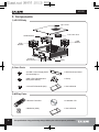
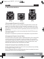
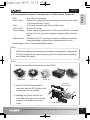
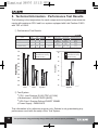
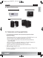
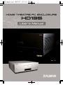
ENGLISH Ver. 1.0 ENGLISH HD135 English ඞ Please read this manual thoroughly before installation. ඞ Visit our website and watch the HD135 installation video first to assist you in the installation process. E-mail: [email protected] w w w. z a l m a n . c o . k r w w w. z a l m a n u s a . c o m HD135 ඟ Introduction Congratulations on your purchase of Zalman's HD135 Home Theatre PC Enclosure! You are now about to experience Zalman's world of silent computing. The HD135 is designed for ultra quiet home theatre PC operation, utilizing optimized ventilation and anti-vibration reinforcements, making it ideal for environments that require silence such as living rooms, bedrooms, educational facilities, and offices. ඟ Contents 1. Safety Notices . . . . . . . . . . . . . . . . . . . . . . . . . . . . . . . . . . . . . . . . . . . . . . . 3 2. Design . . . . . . . . . . . . . . . . . . . . . . . . . . . . . . . . . . . . . . . . . . . . . . . . . . . . . 3 3. Components . . . . . . . . . . . . . . . . . . . . . . . . . . . . . . . . . . . . . . . . . . . . . . . . . 4 4. Features . . . . . . . . . . . . . . . . . . . . . . . . . . . . . . . . . . . . . . . . . . . . . . . . . . . . 5 5. Specifications . . . . . . . . . . . . . . . . . . . . . . . . . . . . . . . . . . . . . . . . . . . . . . . . 7 6. Installation Guide . . . . . . . . . . . . . . . . . . . . . . . . . . . . . . . . . . . . . . . . . . . . . 8 7. Recommended Use . . . . . . . . . . . . . . . . . . . . . . . . . . . . . . . . . . . . . . . . . . .16 8. Technical Information . . . . . . . . . . . . . . . . . . . . . . . . . . . . . . . . . . . . . . . . . .18 9. Zalman Enclosures . . . . . . . . . . . . . . . . . . . . . . . . . . . . . . . . . . . . . . . . . . .19 10. Trademarks and Copyright Notice . . . . . . . . . . . . . . . . . . . . . . . . . . . . . . .19 2 The specifications of any product may change without prior notice to improve performance. 1. Safety Notices 1) Avoid inserting finger or any objects into the system while the power is ON. It may harm the user or cause product damage. 2) Make sure to check the manual when connecting the cable. Improper connection can cause fire resulting from short circuit. 3) Always shut down the operating system and switch the power to OFF before disassembling. 4) The air vents on four sides of the unit must not be blocked. 5) Use in a flat, stable, and well-ventilated area. 6) Keep this unit away from heat sources and direct sunlight. 7) If this unit is to be transported a long distance, then place it in the original packaging box or a custom made hard case. 8) Do not drop or expose this unit to shock while it is in transit. 9) Check the condition of the unit and its components before installation. If there is a problem with the unit and/or its components, please contact the retailer for a replacement. ENGLISH HD135 ඞ Disclaimer Zalman Tech Co., Ltd. is not responsible for any damages due to external causes, including but not limited to, improper use, problems with electrical power, accident, neglect, alteration, repair, improper installation, or improper testing. 2. Design Korean Design Application No. 06-0020894 International design applications pending in the EU, USA, Japan, and 30+ other countries. The specifications of any product may change without prior notice to improve performance. 3 HD135 3. Components 1) HD135 Body Top Cover Fan & Air Duct ODD Bracket HDD Bracket HDD Bracket External Drive Cover Body 2) Case Parts 24 HDD / Power Supply Bolts (PH #6-32X6) 24 1 ODD Aluminum Bezel ODD / FDD / Motherboard Bolts (PWH M3X5) 1 Clamp 2 microATX Standoffs (M3) 1 User's Manual 3) M-Play Parts 4 1 Remote Controller 1 Installation CD 2 Batteries (AAA) 1 User's Manual The specifications of any product may change without prior notice to improve performance. 4. Features 1) Optimized Design for Silence A. Designed for High TDP Processors: Air Duct and two Fans allow quiet cooling of up to 130W TDP CPU processors (Intel Pentium D 830, 840, 940, 950, 960 etc.). ENGLISH HD135 B. Designed for High Performance Power Supply: Air Vents allow cold air intake from outside the PC directly into the Power Supply to minimize its noise level and to achieve highest possible efficiency. C. Designed for VGA Cards: Air Vents around the VGA card allow optimal operation of VGA card by offering maximum cooling capability. D. Designed for Hard Disks: Air Vents located on the bottom and sides of the HDD Bracket allow efficient release of heat generated by the hard disks. 2) Elegant Design A. Pure aluminum surface provides an elegant addition to other Home Theatre and A/V equipments. B. VFD installed on the front panel of the enclosure provides the user with various information such as the operating software status, time display when the power is OFF, and fan speed. The specifications of any product may change without prior notice to improve performance. 5 HD135 3) Diverse Functions and Accommodations A. Microsoft MCE-compatible remote control and multimedia software are provided. This enables the user to easily control the PC and execute various multimedia software. B. USB2.0 ports on the front panel and the IEEE1394 (Firewire) I/O Port allows easy access to connections. A headphone and microphone can also be conveniently connected to the audio ports in the front. C. Sliding-type HDD and ODD Brackets provide easy installation/removal. 4) Excellent Expandability A. Six 3.5" bays and one 5.25" bay provide the user with maximum expandability compared to other enclosures of identical size. B. Accommodation for ATX/ATX 12V power supplies despite the unit's height being identical to that of a common audio device. 5) Ideal Home Theatre PC A quiet and stable Home Theatre PC can be assembled when used with Zalman's CPU Cooler, VGA Cooler, Power Supply, and Northbridge Cooler (CNPS8000, VF700, VF900, ZM460B-APS, ZM-NBF47 etc.). 6 The specifications of any product may change without prior notice to improve performance. HD135 ½ Enclosure Type ½ Dimensions (LXWXH) ½ ½ ½ ½ ½ ½ Weight Material Motherboard Compatibility Power Supply Support PCI/AGP Card Support Drive Bays ½ Cooling Components ½ Expansion Slots ½ Front I/O Ports ½ Available Colors ½ Display Type ENGLISH 5. Specifications - Desktop - 435mm X 425mm X 135mm (17.1inch X 16.7inch X 5.31inch) - 5.2kg (11.5lb) - Aluminum - ATX / microATX - ATX / ATX 12V - Full Size - 5 X 3.5" Internal Drive Bays - 1 X 3.5" External Drive Bay - 1 X 5.25" External Drive Bay - 1 X 80mm Exhaust Fan - 1 X 80mm Inflow Fan and Air Duct - 7 Slots - 2 X USB Ports - 1 X IEEE1394(Firewire) Port - 1 X MIC - 1 X Headphone - Silver / Black - VFD (Vacuum Fluorescent Display) The specifications of any product may change without prior notice to improve performance. 7 HD135 6. Installation Guide 1) Opening the Enclosure To remove the lid of the enclosure, unscrew the two Bolts (Finger Bolt, #6-32) and slide backwards and lift the Top Plate as shown in the figure below. Finger Bolt (#6-32) TOP Plate 2) Removing the ODD and HDD Brackets Remove the Fixing Bolts (Bolt, PH M4x5), and push the ODD and HDD Brackets towards the back of the enclosure by approximately 15mm(0.6inch). Now lift the Brackets. okkGi vkkGi i OwoGt[\P 8 The specifications of any product may change without prior notice to improve performance. 3) Assembling the Motherboard and Power Supply Mount the motherboard and power supply by using appropriate bolts. Mount the computer components (CPU, VGA, RAM etc.) onto the motherboard. Bolt (PWH M3x5) ENGLISH HD135 Power Supply Motherboard Bolt (PH #6-32X6) Note) 1. To mount a microATX motherboard, first attach the two provided microATX Standoffs and align them with the height of the ATX Standoffs. ATX Standoff microATX Standoff 2. Rotational direction of the PCI Card Fixing Bracket The specifications of any product may change without prior notice to improve performance. 9 HD135 4) Installing 5.25" and 3.5" Drives (1) To install the FDD and Card Reader onto HDD Bracket, the External Drive Cover assembled on the Front Plate must first be removed. (2) Attach the 5.25" drive (ODD) and 3.5" drive (HDD, FDD, Card Reader) onto the ODD and HDD Brackets with the use of appropriate Bolts. (3) Push the ODD and HDD Brackets into the enclosure, and install them onto the Front Plate with the use of Fixing Bolts (Bolt, M4x5). Bolt (PH M4x5) Bolt (PH #6-32 x 6) Bolt (PWH M3x5) HDD Bracket ODD Bracket Bolt (PH #6-32 x 6) Front Plate External Drive Cover Bolt (PH M3X5) Note) This product is provided with one 5.25' bay and six 3.5' bays. For optimal HDD cooling, install in the order mentioned in the diagram below. HDD (3.5” ) HDD (3.5” ) HDD (3.5” ) ODD (5.25” ) HDD (3.5” ) HDD (3.5” ) External Drive (3.5” ) 10 The specifications of any product may change without prior notice to improve performance. 5) Deciding on Air Duct Location Install the Air Duct connected to the Top Plate right above the CPU cooler for optimal CPU cooling. ENGLISH HD135 Top Plate Air Duct Note) CPU cooler performance will drastically decrease if the installation is made without the Air Duct. Also minimize the distance between the Air Duct and the CPU cooler by adjusting the length of the Air Duct. 6) Connecting the Cables (1) Power and Data Transmission Cables Connect the Power and Data Transmission cables (IDE or SATA) required for the HDD, ODD, FDD, VGA etc. (2) Power LED Cable Connect the Power LED Connector (2-Pin or 3-Pin) connected to the Power PCB to the motherboard's Front Panel Port (refer to the motherboard manual). VFD Power PCB Power LED Connector Motherboard Front Panel Port Note) The Case Power SW Connector of the Power PCB is already connected to the VFD as shown in the picture. The specifications of any product may change without prior notice to improve performance. 11 HD135 (3) Front I/O Cable Connect the USB Cable, 1394(Fire Wire) Cable, and Audio Cable to the motherboard as explained in the motherboard manual. mGw G} mGpVvGw 12 The specifications of any product may change without prior notice to improve performance. (4) VFD Multi-Cable ྙ Connect the VFD Power Connector to the Power Supply Connector. ྚ Connect the VFD USB Connector to the motherboard's USB Port. ENGLISH HD135 Front Plate inside View VFD VFD Power Connector Power Supply Connector VFD Motherboard USB Port VFD USB Connector Note) 1. Must refer to the motherboard manual for the USB Port Pin arrangement when connecting the VFD USB cable. Incorrect connection can cause damage to the VFD resulting from a short circuit. 2. VFD USB Cable Colors GND : Black, +DATA : Green, -DATA : Blue, USB +5V : Red The specifications of any product may change without prior notice to improve performance. 13 HD135 ྛ Place the Temperature Sensor on a place of preference inside the Enclosure. ྜ Connect the Motherboard Power Connector to the motherboard's Front Panel Port (refer to the motherboard manual). ྜྷ Connect the Fan Connector to the Fan installed on the Top Cover, and assemble the Top Cover. Bottom Plate Fan Top Cover Fan Fan Connector VFD Motherboard Front Panel Port Motherboard Power Connector Temp. Sensor 1 Temp. Sensor 2 Case Power SW Header Case Power SW Connector Note) Tie the VFD multi-cables with the enclosed Clipper, and fix them on to the Bottom Plate with the use of a Clipper to ensure that the cables are not disconnected from the VFD. 14 The specifications of any product may change without prior notice to improve performance. 7) Attaching the Aluminum ODD Bezel (1) Connect power to the assembled system. Press the ODD Eject button to eject the ODD Tray. (2) Remove the plastic ODD Bezel. (3) Expose the Tape Film on the inside of the aluminum ODD bezel, and stick the aluminum ODD bezel to the ODD tray. ENGLISH HD135 ODD Tray Aluminum ODD Bezel Plastic ODD Bezel ODD Eject Button Tape Film Aluminum ODD Bezel Note) If you are facing difficulties in removing the plastic ODD bezel, then please contact the place of purchase or the ODD manufacturer. 8) Installing the Multimedia Software Refer to the enclosed M-Play Quick Guide manual to install the software. The specifications of any product may change without prior notice to improve performance. 15 HD135 7. Recommended Use (O) (O) (X) 1) Recommended Placement for the HD135 Placement of this system on a well-ventilated area (good intake of cold air and release of hot air) allows efficient cooling of computer components even in low RPM mode, which is the quietest operation. The noise level of the power supply (main factor of noise emission) will also significantly decrease due to better cooling efficiency. There must be good airflow on the front and back side of the HD135 when placing it inside a cabinet. Any other AV components or products must not be placed on top of the HD135. 2) Arrangement of System's Internal Cables The internal airflow of the system makes a significant impact on the cooling of the computer components. Even though the ergonomic design of the case itself is very important, tying all the cables in a neat manner is the best method for creating great internal airflow. Pay special attention to make sure that the air vents, and intake and exhaust fans are not blocked by the cables. 3) Optimal Fan Speed Control with M-Play Fan Control Cooling performance and noise level can be set to user preference by controlling the fan speed in M-Play's A.F.C mode. Use the Temperature Sensor and the M-Play Fan Control to maintain the internal temperature of the unit to be no greater than 40. 16 The specifications of any product may change without prior notice to improve performance. 4) Recommended Computer Components for a Silent Home Theatre PC ½ CPU ½ CPU Cooler ½ ½ ½ ½ ½ : Any CPU in the market : Silent CPU cooler with great cooling performance and height of less than 69cm(2.7inch) VGA : VGA card equipped with a silent VGA cooler VGA Cooler : Silent VGA cooler Power Supply : Power Supply equipped with a 120mm fan(HD135 is provided with an Air Vent for power supplies equipped with a 120mm Fan). Motherboard : Standard Full-ATX (with great distance between the internal heat-generating components) motherboard with no fan. Northbridge Cooler : Fanless Northbridge cooler. ENGLISH HD135 Note) HD135 is designed to have the same height as standard AV equipments. The SLI Connector prevents the closing of the Top Plate when installing two nVidia VGA cards. Note) 1. Recommended Zalman products for the HD135 CNPS 8000 VF900- CU VF700- CU ZM460- APS PCI Card Fixing Bracket 2. If the PCI Card Fixing Bracket is removed, then the PCI Card can be fixated with the use of Bolts. 3. Installing two 60mm fans on the Rear Plate will reduce internal temperature, but might cause more noise. ZM-NBF 47 Fan(60mm) The specifications of any product may change without prior notice to improve performance. 17 HD135 8. Technical Information : Performance Test Results The following is the temperature for each component and system noise measurements with maximum CPU load for a system equipped with Intel Pentium D 830 with TDP of 130W. ྙ Performance Test Results System Component Temperature ( ) CPU VGA System System Noise (dBA) Silent Optimal Cooling 67.54 52.18 46.60 30.70 Silent Maximum Cooling 60.59 46.33 41.78 41.70 Standard Cooling 66.23 44.46 43.46 50.6 70 CPU Cooler CNPS8000 (5V) VF700-CU (5V) 80mm (5V) CNPS8000 (12V) Intel Stock Cooler VF700-CU (12V) 80mm (12V) 80mm (12V) 60 Silent Optimal Cooling Silent Maximum Cooling 65 Test Condition VGA Cooler Intake/Exhaust Fan Stock Cooler Silent Optimal Cooling Silent Maximum Cooling 55 Standard Cooling Standard Cooling 60 50 45 50.6 40 35 30 30.7 30 45 41.7 43.46 41.78 46.6 35 44.46 46.33 52.18 40 66.23 60.59 67.54 50 Noise (dBA) 55 25 25 1 CPU VGA2 3 System 1 System ྚ Test System ඟ CPU : Intel Pentium D 830 (TDP of 130W) ඟ Motherboard : ASUS PSLD2 (i945P) ඟ VGA Card : Evertop Geforce7800GT 256MB ඟ Power Supply : ZM460-APS This information is for reference purpose only. Zalman is not guaranteeing any performance result with the setup of the Test System. 18 The specifications of any product may change without prior notice to improve performance. 9. Zalman Enclosures Home Theare Computer Enclosure Gaming Computer Enclosure < HD160 > ENGLISH HD135 <FC-ZE1 > TNN (Totally No Noise) Computer Enclosure < TNN300 > < TNN500AF > 10. Trademarks and Copyright Notice ̱ All trademarks mentioned in this manual are properties of their respective owners. - ZALMAN and HD135 are registered trademarks of ZALMAN Tech Co., Ltd. - Intel and Pentium D are registered trademarks of Intel Corp. - VGA are registered trademarks of International Business Machines Corporation (IBM). - ASUS and PSLD2 are registered trademarks of Asustek Computer Inc. - Evertop is a registered trademark of Evertop. Co., Ltd. - NVDIA, GeForce are registered trademarks of NVIDIA Corp. ̱ 2006 by Zalman Tech Co., Ltd. Copying or publishing this user's manual without the consent of Zalman Tech Co., Ltd. is prohibited. The specifications of any product may change without prior notice to improve performance. 19