1
CLOTHES DRYER
Model code : DV316LGW/XAA
DV306LEW/XAA
DV316LEW/XAA
DV326LES/XAA
DV3C6BEW/XAA
DV316BEW/XAA
DV316BEC/XAA
DV306LGW/XAA
DV316LGW/XAA
DV316LGS/XAA
DV326LGS/XAA
DV3C6BGW/XAA
DV316BGW/XAA
DV316BGC/XAA
SERVICE
Manual
CLOTHES DRYER
THE FEATURE OF PRODUCT
1. Super Size Capacity
2. Energy Saving
3. Time Saving
SAM0109
CONTENTS
1. PRECAUTIONS
1-1. CAUTION FOR SAFETY DURING SERVICING................................................................................1-1
1-2. IMPORTANT SAFETY INFORMATION..............................................................................................1-2
1-3. PRECAUTIONS UPON INSTALLATION............................................................................................1-6
2. PRODUCT SPECIFICATIONS
2-1. THE FEATURE OF PRODUCT..........................................................................................................2-1
2-2. SPECIFICATIONS
�������������������������
OF PRODUCT.....................................................................................................2-2
2-3. OVERVIEW OF THE DRYER............................................................................................................2-3
2-4. THE COMPARATIVE SPECIFICATIONS OF PRODUCT..................................................................2-4
2-5. OPTION SPECIFICATIONS.
�������������� ..............................................................................................................2-5
3. OPERATING INSTRUCTIONS AND INTALLATION
3-1. OVERVIEW OF THE CONTROL PANEL...........................................................................................3-1
3-2. CYCLE CHART..................................................................................................................................3-3
3-3. MAIN FUNCTIONS............................................................................................................................3-4
3-4. DESIGNATION OF MAIN COMPONENTS........................................................................................3-6
4. ALIGNMENT AND ADJUSTMENTS
4-1. ERROR ITEMS AND DIAGNOSTIC CODES.....................................................................................4-1
4-2. TEST MODE......................................................................................................................................4-2
5. DISASSEMBLY AND REASSEMBLY
5-1. TOOLS FOR DISASSEMBLY AND REASSEMBLY...........................................................................5-1
5-2. DISASSEMBLY..................................................................................................................................5-2
5-3. REASSEMBLY...................................................................................................................................5-6
6. TROUBLE SHOOTING
6-1. TROUBLE DIAGNOSIS.....................................................................................................................6-1
6-2. PROBLEM CHECKING AND METHOD OF PCB..............................................................................6-3
7. EXPLODED VIEWS AND PARTS LIST
7-1. EXPLODED VIEW OF FRAME, PANEL-CONTROL..........................................................................7-1
7-2. EXPLODED VIEW OF FRONT..........................................................................................................7-3
7-3. EXPLODED VIEW OF DRUM............................................................................................................7-4
7-4. EXPLODED VIEW OF DUCT, HEATER, MOTOR.............................................................................7-5
7-5. BOLT & SCREW PARTS LIST...........................................................................................................7-6
CONTENTS
8. ELECTRICAL PARTS LIST......................................................................................................................8-1
9. BLOCK DIAGRAM...................................................................................................................................9-1
10. WIRING DIAGRAM..............................................................................................................................10-1
11. PCB DIAGRAM..................................................................................................................................... 11-1
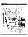
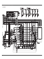
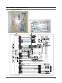
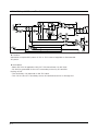
12. SCHEMATIC-DIAGRAMS ..................................................................................................................12-1
13. CIRCUIT DESCRIPTIONS...................................................................................................................13-1
14. REFERENCE INFORMATION
14-1. MODEL NAME...............................................................................................................................14-1
14-2. TERMINOLOGY.............................................................................................................................14-2
14-3. CHECK THESE POINTS IF YOUR DRYER..................................................................................14-4
14-4. INFORMATION CODES................................................................................................................14-5
14-5. FABRIC CARE CHART..................................................................................................................14-6
41#SUHFDXWLRQV
4041#FDXWLRQ#IRU#VDIHW\#GXULQJ#VHUYLFLQJ
1. Do not allow the customer to repair the product.
The person may be injured or the product life may be shortened..
2. Execute A/S after unplugging the power supply unit.
Be careful of the electric shocks.
3. Do not plug several plugs in the same outlet.
It may cause a fire due to overheat.
4. Check for damage, pressing or burning of the power plug or outlet.
Replace it promptly if it has a problem.(It may cause the electric shocks or fire)
5. Do not clean the main body with water.
It may cause electric shocks and fire and shorten the product life)
6. The wiring of the harness shall be free from moisture and tightened during serving.
It shall not be deviated by certain impact.
7. Remove any dust or filth on the housing section,wiring section,connection section during servicing.
Protect from possible cause of fire such as the tracking,shortage etc.
8. Check for any marks of moisture on the electrical parts, harness section etc.
Replace the parts or remove the moisture..
9. Check the assembly status of the parts after servicing.
Maintain the status before servicing..
10. Pull out the power cord by holding the plug.
Be careful of electric shocks and when the cord is damaged.
11. Unplug the power plug from the outlet when the dryer is not used.
Be careful of electric shocks and fire due to the strike of lightning.
12. Do not use or store sprays or flammable materials(including gasoline,alcohol etc.)
around the dryer.
Be careful of explosions or fire due to electric sparks.
13. Do not put bowls of water or wet laundry on the dryer.
If water has penetrated into the dryer, this may cause electric shocks or fire.
14. Do not install the dryer where it will be exposed to bad weather.
It may cause electric shocks and fire and shorten the product life.
1-1
15. Do not push the control buttons with an awl,pin, or sharp materials.
It may cause electric shocks and damage.
16. Check the wash machine is leveled horizontally and installed properly on the floor.
The vibration may shorten the product life..
4051#LPSRUWDQW#VDIHW\#LQIRUPDWLRQ
To avoid risk of fire, electric shock, serious injury, or death when using your dryer, follow these basic precautions:
1. Read all instructions before using dryer.
2. Install dryer according to Installation Instructions. Refer to the Grounding Instructions in the
Installation Instructions for proper grounding of the dryer.
3. Do not dry articles that have been cleaned in, washed in, soaked in, or spotted with gasoline, drycleaning solvents, or other flammable or explosive substances. Vapors could ignite or explode.
4. Do not use dryer to dry clothes which have traces of any flammable substance, such as vegetable oil,
cooking oil, machine oil, flammable chemicals, thinner, etc., or anything containing wax or chemicals,
such as mops and cleaning cloths. Flammable substances may cause fabric to catch fire by itself.
5. Do not store or use gasoline or other flammable vapors and liquids near this or any other appliance.
6. Do not allow children to play on or in dryer. Close supervision of children is necessary when dryer is
used near children, a safety rule for all appliances.
7. Before dryer is removed from service or discarded, remove doors to drying compartment.
8. Do not reach into dryer if cylinder is revolving.
9. Do not install or store dryer where it will be exposed to water and/or weather.
10. Do not tamper with dryer controls.
11. Do not repair or replace any part of dryer or attempt any service, unless specifically recommended in
user-maintenance instructions or in published user-repair instructions that you understand and have
skills to carry out, if you are a consumer.
12. To reduce risk of electric shock or fire, do not use extension cords or adapters to connect dryer to
electrical power source.
13. Use the dryer only for its intended purpose, drying clothes.
14. Always disconnect dryer from electrical supply before attempting any service. Disconnect power cord by
grasping the plug, not the cord.
15. Do not use heat to dry articles containing foam rubber or similarly textured rubberlike materials.
1-2
16. Always clean the lint filter after every load. A layer of lint in the filter reduces drying efficiency and pro
longs drying time.
17. Use only fabric softeners or products to eliminate static that are appropriate for automatic dryers.
18. Keep your dryer in good condition. Bumping or dropping dryer can damage safety features. If damage
occurs, have dryer checked by qualified service technician.
19. Replace worn power cords and/or loose plugs.
20. Do not tumble fiberglass curtains and draperies unless the label says it can be done. If they are dried, wipe
out the cylinder with a damp cloth to remove particles of fiberglass.
21. Always read and follow manufacturers instructions on packages of laundry aids. Heed all warnings or
precautions. To reduce risk of poisoning or chemical burns, keep products away from children at all times,
preferably, in a locked cabinet.
22. Never operate dryer with guards and/or panels removed.
23. Do not operate dryer with missing or broken parts.
24. Do not bypass safety devices.
25. Keep area around the exhaust opening and adjacent surrounding areas free from accumulation of
lint, dust, and dirt.
26. Interior of dryer and exhaust duct should be cleaned periodically by qualified service personnel.
27. Dryer will not operate with loading door open. DO NOT bypass door safety switch by permitting dryer to
operate with door open. Dryer will stop tumbling when door is opened. Do not use dryer if it does not stop
tumbling when door is opened or starts tumbling without pressing or turning the START mechanism.
Remove the dryer from use and call the service person.
28. Remove laundry immediately after the dryer stops.
29. ALWAYS follow the fabric care instructions supplied by the garment manufacturer.
1-3
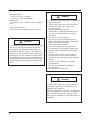
Hohfwulfdo#Vhuylfh#Lqirupdwlrq
Electrical Dryers
- 240 VAC, 60 Hz, 30 Amps,
3-wire or 4-wire installations
Gas Dryers
- 120 VAC, 60 Hz, 15 Amps, 3wire installations
About Ground Wires
In the event of an electrical short circuit, a
ZDUQLQJ
To reduce the risk of fire, electric shock, serious injury or death, all wiring and grounding must conform with the latest edition of
the National Electric Code, or the Canadian
Electrical Code, and such local regulations as
might apply. It is the customers responsibility to have the wiring and fuses checked by a
qualified electrician to make sure your home
has adequate electrical power to operate the
dryer.
ZDUQLQJ
To avoid risk of personal injury or death due
to electrical shock:
- Observe all local codes and ordinances.
- Disconnect electrical power to unit
before servicing.
- Ground appliance properly.
- Check with a qualified electrician if you
are not sure this appliance is properly
grounded.
- DO NOT ground to gas line.
- DO NOT ground to cold water pipe if
pipe is interrupted by plastic, nonmetallic
gas kets, or other insulating
(nonconducting) materials.
- DO NOT modify plug on power cord.
If plug does not fit electrical outlet, have
proper outlet installed by qualified elec
trician.
- DO NOT have a fuse in the neutral or
ground circuit. A fuse in the neutral or
ground circuit could result in an electrical
shock.
- DO NOT use an extension cord with
this appliance.
- DO NOT use an adapter plug with
this appliance.
- DO NOT pinch powe cord.
ZDUQLQJ
To reduce the risk of fire and exposure to
combustion gases, the dryer MUST be exhausted to the outdoors.
DO NOT exhaust dryer air into a window well,
gas vent, chimney or enclosed, unventilated
area, such as an attic, wall, ceiling, crawl
space under a building or concealed space of
a building.
1-4
Jdv#Gu|hu#Srzhu#Vxsso|
This equipment MUST be grounded. In the
event of an electrical short circuit, grounding
reduces the risk of electric shock by providing
an escape wire for the electrical current. This
unit is equipped with a cord having a grounding wire with a grounding plug. The plug must
be plugged into an outlet that is properly
installed and grounded.
Consult a qualified electrician or servicer if
grounding instructions are not completely understood, or if doubt exists as to whether the
equipment is properly grounded.
Do not use an extension cord. If the product power cord is too short, have a qualified
electrician install a three slot receptacle.
This unit should be plugged into a separate 60
hertz circuit with the electrical rating as shown
on the serial plate.
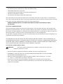
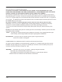
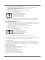
Surshu#Jurxqglqj#dqg#Srodul}dwlrq#iru#453#
YrowvZdoo#Rxwohwv
For the safety of our customers and the service technician ALL gas dryers have a three!!
prong power cord and MUST be connected to
a properly polarized and grounded wall outlet.
This information was written for those who do
not understand grounding and polarization
of a wall outlet. A 120 VAC wall outlet must
always be wired as shown below.
connection to the main power panel.
Xqjurxqghg-The round hole connection is not
connected to a ground and/or the main power
panel.
Jdv#Frqqhfwlrq#Lqirupdwlrq
ZDUQLQJ
To avoid death, personal injury or property
damage, from fire or explosion, information
in this manual must be followed exactly.
Do not store or use gasoline or other flammable vapors and liquids in the vicinity of this
or any other appliance.
ZKDW#WR#GR#LI#\RX#VPHOO#JDV
- Do not try to light any appliance.
- Do not touch any electrical switch; do not
use any phone in your building.
- Immediately call your gas supplier from a
neighbor’s phone. Follow the gas suppli
er’s instructions.
- If you cannot reach your gas supplier, call
the fire department.
Installation and service must be performed
by a qualified installer, service agency or
the gas supplier.
ZDUQLQJ
To reduce the risk of fire and exposure to
combustion gases, the dryer MUST be exhausted to the outdoors.
DO NOT exhaust dryer air into a window well,
gas vent, chimney or enclosed, unventilated
area, such as an attic, wall, ceiling, crawl
space under a building or concealed space of
a building.
Srodul}dwlrq-This means that the larger slot
must be neutral and the small slot must be hot
(live).
Plvsrodul}hg-The outlet is miswired so that the
larger slot is hot (live) and the smaller slot is
neutral.
Jurxqghg -This means the round hole connection is connected to ground through a
1-5
4061#SUHFDXWLRQV#XSRQ#LQVWDOODWLRQ
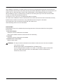
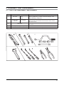
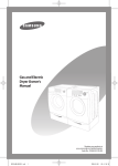
Tools needed for installation
Proper installation is the owner’s responsibility.
HOWEVER, SERVICE CALLS PERFORMED AS A RESULT OF POOR SET-UP, ADJUSTMENT, AND CONNECTION ARE THE
RESPONSIBILITY OF THE INSTALLER.
Make sure you have everything necessary for proper installation.
1. GROUNDED ELECTRICAL OUTLET is required. See Electrical Requirements.
2. POWER CORD for electric dryers (except Canada).
3. GAS LINES (if a gas dryer) must meet national and local codes.
4. EXHAUST SYSTEM – must be rigid metal or flexible stiffwalled metal exhaust ducting.
See Exhaust Requirements.
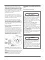
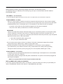
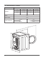
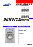
Control
panel
Adjustable
Door
Adjustable leg
1-6
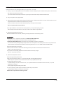
Pliers
Cutting knife
Pipe wrench
(gas only)
Nut drivers
Level
Screwdriver
(standard)
Duct tape
Crescent
spanner
DUCTING REQUIREMENTS
• Use a 4-inch (10.2 cm) diameter rigid aluminum or rigid galvanized steel duct.
• Do not use a smaller duct.
• Ducts larger than 4 inches (10.2 cm) in diameter can result in increased lint accumulation.
Lint accumulation should be cleaned regularly.
• If a flexible metal duct must be used, use the type with a stiff sheet metal wall. Do not use a flexible
duct with a thin foil wall. Serious blockage can result if the flexible metal duct is bent too sharply.
• Never install any type of flexible duct in walls, ceilings, or other concealed spaces.
• Keep exhaust duct as straight and short as possible.
• Secure joints with duct tape. Do not use screws.
• DO NOT EXHAUST DRYER INTO ANY WALL, CEILING, CRAWL SPACE, OR CONCEALED SPACE OF A
BUILDING, GAS VENT, OR ANY OTHER COMMON DUCT OR CHIMNEY.
THIS COULD CREATE A FIRE HAZARD FROM LINT EXPELLED BY THE DRYER.
• Plastic flexible duct can kink, sag, be punctured, reduce airflow, extend drying times, and affect dryer
operation.
• Exhaust systems longer than recommended can extend drying times, affect machine operation, and may collect lint.
• The exhaust duct should end with an exhaust hood with a swing-out damper to prevent back drafts
and entry of wildlife. Never use an exhaust hood with a magnetic damper.
• The hood should have at least 12 inches (30.5 cm) of clearance between the bottom of the hood and
the ground or other obstruction. The hood opening should point down.
• Never install a screen over the exhaust outlet.
• To avoid lint buildup, do not exhaust the dryer directly into a window well. Do not exhaust under a
house or porch.
• If exhaust ductwork must run through an unheated area, the duct should be insulated and slope
slightly down towards the exhaust hood to reduce condensation and lint buildup.
• Inspect and clean the interior of the exhaust system at least once a year. Unplug the power cord
before cleaning.
• Check frequently to be sure the exhaust hood damper opens and closes freely.
ELECTRIC AND GAS DRYER
Weather Hood Type
Recommended
4” (10 .16 cm)
Use only for short-run installation
2.5” (6.35 cm)
No. of 90°
elbows
Rigid
Metallic Flexible*
Rigid
Metallic Flexible*
0
24.4 m (80 ft.)
12.4 m (41 ft.)
22.6 m (74 ft.)
10.1 m (33 ft.)
1
20.7 m (68 ft.)
11.2 m (37 ft.)
18.9 m(62 ft.)
8.8 m (29 ft.)
2
17.4 m (57 ft.)
10.1 m (33 ft.)
15.5 m(51 ft.)
7.6 m (25 ft.)
3
14.3m (47 ft.)
9.0 m (29 ft.)
12.5 m(41 ft.)
6.5 m (21 ft.)
* Do not use non-metallic flexible duct.
1-7
If new dryer is installed into an existing exhaust system you must make sure:
•
•
•
•
•
The exhaust system meets all local, state, and national codes.
That flexible plastic duct is not used.
Inspect and clean all lint buildup from inside the existing duct.
The duct is not kinked or crushed.
The exhaust hood damper opens and closes freely.
The static pressure in any exhaust system must not exceed 0.83 inches of water column, or be less than 0.
This can be measured with the dryer running with a manometer at the point where the exhaust duct connects
to the dryer. A no-heat setting should be used. The dryer tumbler shoul
REMOVE THE DOOR FROM ALL DISCARDED APPLIANCES TO AVOID THE DANGER OF A CHILD
SUFFOCATING.
LOCATION CONSIDERATIONS
The dryer should be located where there is enough space in front for loading the dryer, and enough space
behind for the exhaust system. This dryer is factory-ready for rear exhaust. To exhaust out the bottom or the
left, use the accessory exhaust kit. Instructions are included with the kit. It’s important to make sure the room
has enough fresh air. The dryer must be located where there is no air-flow obstruction.
On gas dryers, adequate clearance as noted on the data plate must be maintained to ensure adequate air for
combustion and proper dryer operation.
THE DRYER MUST NOT BE INSTALLED OR STORED IN AN AREA WHERE IT WILL BE EXPOSED TO
WATER AND/OR WEATHER. THE DRYER AREA IS TO BE KEPT CLEAR OF COMBUSTIBLE MATERIALS,
GASOLINE, AND OTHER FLAMMABLE VAPORS AND LIQUIDS. A DRYER PRODUCES COMBUSTIBLE
LINT. THE AREA AROUND THE DRYER SHOULD BE KEPT LINT-FREE.
ALCOVE OR CLOSET INSTALLATION
WARNING –
The dryer must be exhausted to the outside to reduce the risk of fire when
installed in an alcove or closet.
• No other fuel-burning appliance should be installed in the same closet as the dryer.
• WARNING: To reduce the risk of fire, this dryer MUST BE EXHAUSTED TO THE OUTDOORS.
See EXHAUST INFORMATION section.
• Minimum clearances between the dryer and adjacent walls or other surfaces are: 2” in front,
17” on top, 1” on either side, and 2.375” in the back.
• Closet front must have two unobstructed air openings for a combined minimum total area of
72 in² with 3” minimum clearance on the top and bottom. A louvered door with equivalent space
clearance is acceptable.
1-8
MOBILE HOME INSTALLATION
The installation of the dryer in mobile homes must conform to the Manufactured Home Construction and
Safety Standard Title 24 CFR, Part 32-80 {formerly the Federal Standard for Mobile Home Construction and
Safety, Title 24, HUD (Part 280), 1975} for the United States) or CSA Standards Z240 (for Canada).
When installing a dryer in a mobile home, provisions for anchoring the dryer to the floor must be made.
Locate in an area that has adequate fresh air.
A minimum of 72 in² (183 cm² ) of unobstructed space is required.
All mobile home installations must be exhausted to the outside with the exhaust duct termination securely
fastened to the mobile home structure, using materials that will not support combustion.
The exhaust duct may not terminate underneath the mobile home.
See Exhausting section for more information.
EXHAUSTING
Exhausting the dryer to the outside will prevent large amounts of lint and moisture from being blown
into the room.
In the United States:
• All dryers must be exhausted to the outside.
• Only rigid or flexible metal duct should be used for exhausting.
In Canada:
• All dryers must be exhausted to the outside.
Outside the U.S. and Canada:
• Refer to local codes.
WARNING –The dryer must be exhausted to the outside to reduce the risk of fire when installed
n an alcove or closet.
NEVER USE PLASTIC OR NON-METAL FLEXIBLE DUCT.
If your existing ductwork is plastic, non-metal, or combustible, replace it with metal.
Use only metal exhaust duct that is non-flammable to ensure containment of
exhaust air, heat, and lint.
1-9
GAS REQUIREMENTS
Use only natural or LP (liquid propane) gases.
THE INSTALLATION MUST CONFORM WITH LOCAL CODES, OR IN THE ABSENCE OF LOCAL
CODES, WITH THE NATIONAL FUEL GAS CODE ANSI/Z223.1, LATEST REVISION (FOR THE UNITED
STATES), OR WITH THE CAN/CGA-B149 INSTALLATION CODES (FOR CANADA).
Gas dryers are equipped with a burner vent for use with natural gas. If you plan to use your dryer with LP
(liquid propane) gas, it must be converted for safe and proper performance by a qualified service technician.
A 1/2” (1.27 cm) gas supply line is recommended and must be reduced to connect to the 3/8” (1 cm) gas line
on your dryer. The National Fuel Gas Code requires that an accessible, approved manual gas shut-off valve
be installed within 6’ of your dryer.
Gas dryers installed in residential garages must be raised 18 inches (46 cm) above the floor.
Additionally, a 1/8” (0.3 cm) N.P.T. (National Pipe Thread) plugged tapping, accessible for test gauge
connection, must be installed immediately upstream of your dryer’s gas supply connection.
Your dryer must be disconnected from the gas supply pipe system during any pressure testing of the
system.
DO NOT reuse old flexible metal gas lines. Flexible gas lines must be design certified by the American Gas
Association (CGA in Canada).
NOTE: • Any pipe joint compound used must be resistant to the action of any liquefied petroleum gas.
• As a courtesy, most local gas utilities will inspect a gas appliance installation.
GAS IGNITION – Your dryer uses an automatic ignition system to ignite the burner.
There is no constant burning pilot.
COMMONWEALTH OF MASSACHUSETTS INSTALLATION INSTRUCTIONS
Your dryer must be installed by a licensed plumber or gas fitter. A “T” handle manual gas valve must be
installed in the gas supply line to your dryer. If a flexible gas connector is used to install your dryer, the
connector must have a maximum length of 3’ (36”).
WARNING –
Gas leaks may occur in your system, creating a dangerous situation.
Gas leaks may not be detected by smell alone.
Gas suppliers recommend you purchase and install a UL-approved gas detector.
Install and use in accordance with manufacturer’s instructions.
1-10
ELECTRICAL REQUIREMENTS
NOTE: Wiring diagram is located on plate below the control panel.
WARNING –
• Improper connection of the equipment grounding conductor can result in a risk of electric shock. Check
with a qualified electrician or serviceman if you are in doubt as to whether your dryer is properly
grounded. Do not modify the plug provided with your dryer – if it doesn’t fit the outlet, have a proper
outlet installed by a qualified electrician.
• To prevent unnecessary risk of fire, electrical shock, or personal injury, all wiring and grounding must be
done in accordance with local codes, or in the absence of local codes, with the National Electrical Code,
ANSI/NFPA No. 70-Latest Revision (for the U.S.) or the Canadian Electrical Code CSA C22.1 – Latest
Revisions and local codes and ordinances. It is your responsibility to provide adequate electrical services
for your dryer.
• All gas installations must be done in accordance with the national Fuel Code ANSI/Z2231 – Lastest
Revision (for the U.S.) or CAN/CGA – B149 Installation Codes – Latest Revision (for Canada) and local
codes and ordinances.
GROUNDING
This dryer must be grounded. In the event of malfunction or breakdown, the ground will reduce the risk of
electrical shock by providing a path of least resistance for electrical current.
GAS MODELS
Your dryer has a cord with an equipment-grounding conductor and a grounding plug.
The plug must be plugged into an appropriate outlet that is properly installed and grounded in
accordance with all local codes and ordinances.
Do not modify the plug provided with your dryer – if it doesn’t fit the outlet, have a proper outlet installed
by a qualified electrician.
NEVER CONNECT GROUND WIRE TO PLASTIC PLUMBING LINES, GAS LINES, OR HOT WATER
PIPES.
ELECTRIC MODELS
Your dryer has a cord with an equipment-grounding conductor and a grounding plug.
The plug must be plugged into an appropriate outlet that is properly installed and grounded in accordance
with all local codes and ordinances.
If a power cord is not used and the electric dryer is to be permanently wired, the dryer must be connected
to a permanent grounded metal wiring system, or an equipment grounding conductor must be run with
the circuit conductors and connected to the equipment grounding terminal.
1-11
ELECTRICAL CONNE CTIONS
Before operating or testing, follow all grounding instructions in the Grounding section.
An individual branch (or separate) circuit serving only your dryer is recommended. DO NOT USE AN
EXTENSION CORD.
GAS MODELS – U.S. and Canada
A 120 volt, 60 Hz AC approved electrical service, with a 15-ampere fuse or circuit breaker is required.
ELECTRIC MODELS – U.S. Only
Most U.S. dryers require a 120/240 volt, 60 Hz AC approved electrical service. Some require 120/208
volt, 60 Hz approved electrical service. The electric service requirements can be found on the data label
located behind the door. A 30-ampere fuse or circuit breaker on both sides of the line is required.
• If a power cord is used, the cord should be plugged into a 30-ampere receptacle.
• The power cord is NOT provided with U.S. electric model dryers.
IMPORTANT:
When local codes allow, the dryer electrical supply may be connected by means of a new power supply
cord kit, marked for use with a dryer, that is U.L. listed and rated at a minimum of120/240 volts, 30ampere with three No. 10 copper wire conductors terminated with closed loop terminals, open-end spade
lugs with turned up ends, or with tinned leads.
1. size of the conductors and the type of cord.
2. 3/4” (1.9 cm) UL-listed strain relief
• Do not reuse a power supply cord from an old dryer. The power cord electric supply wiring must be
retained at the dryer cabinet with a suitable UL-listed strain relief.
• Grounding through the neutral conductor is prohibited for (1) new branch-circuit installations,
(2) mobile homes, (3) recreational vehicles, and (4) areas where local codes prohibit grounding
through the neutral conductor. (Use 4-prong plug for 4 wire receptacle, NEMA type 14-30R.)
ELECTRIC MODELS – Canada Only
• A 120/240 volt, 60 Hz AC approved electrical service fused through a 30-ampere fuse or circuit breaker
on both sides of the line is required.
• All Canadian models are shipped with the power cord attached. The power cord should be plugged into
a 30-ampere receptacle.
NOTE: It is not permissible to convert a dryer in Canada to 208 volts.
REPLACEMENT PARTS AND ACCESSORIES
If your dryer requires replacement parts or accessories, contact the dealer from whom you purchased your
dryer or a SAMSUNG customer care center at 1-800-SAMSUNG (726-7864).
1-12
INSTALLATION
Parts and literature are packaged inside your dryer drum. To install:
1. Move your dryer to an appropriate location for installation. Consider installing the dryer and washer side-by-side, to allow access to
gas, electrical, and exhaust connections.
Lay two of the carton cushion-tops on the floor. Tip your dryer on its side so it will lay across both cushion-tops.
2. Set your dryer back in an upright position.
3. Review the Exhausting section before installing the exhaust system. Install the ductwork from your dryer to the exhaust hood. The
crimped end of the duct sections must point away from your dryer.
DO NOT use sheet metal screws when assembling ducting. These joints should be taped.
Never use plastic flexible exhaust material.
Tip for tight installations: install a section of exhaust system to your dryer before putting it in place.
Use duct tape to secure this section to your dryer, but do not cover louvers in dryer cabinet.
4. Review Electrical Requirements section.
BEFORE OPERATING OR TESTING, follow the grounding instructions in the Grounding section.
U.S. MODELS:
IMPORTANT – All U.S. models are produced for a 3-WIRE SYSTEM CONNECTION.
The dryer frame is grounded to the neutral conductor at the terminal block.
A 4-WIRE SYSTEM CONNECTION is required for new or remodeled construction, mobile homes,
or if local codes do not permit grounding through neutral. If the 4-wire system is used, the dryer frame cannot be grounded to the
neutral conductor at the terminal block. Refer to the following instructions for 3- and 4-WIRE SYSTEM CONNECTIONS.
Remove the terminal block cover plate.
Insert the power cord with a UL-listed strain relief through the hole provided in the cabinet near the terminal block.
NOTE: A strain relief must be used.
Do not loosen the nuts already installed on the terminal block. Be sure they are tight.
Use a 3/8” (1cm) deep well socket.
5. Review Gas Requirements section.
Remove the pipe thread protective cap.
Apply pipe joint compound or about 1 1/2 wraps of Teflon tape over all threaded connections.
NOTE: Pipe joint compound must be resistant to the action of any liquefied petroleum gas.
Connect the gas supply to your dryer.
An additional fitting is required to connect the 3/4” (1.9 cm) female thread end of a flexible connector to the 3/8” (1 cm) male
threaded end on the dryer.
Securely tighten the gas line fitting over threads.
Turn on the gas supply. Check all gas connections for leaks using a soap solution.
If bubbles appear, tighten the connections and recheck.
DO NOT use an open flame to check for gas leaks.
1-13
3-WIRE SYSTEM CONNECTIONS
1. Loosen or remove center terminal block screw.
2. Connect neutral wire (white or center wire) of the power cord to the center, silver-colored
terminal screw of the terminal block. Tighten screw.
3. Connect the other wires to outer terminal block screws. Tighten screws.
4. Tighten strain relief screws.
5. Insert tab of terminal block cover into your dryer’s rear panel slot.
Secure cover with hold-down screw.
• External ground connector
• Neutral grounding wire (green/yellow)
• Center silver-colored terminal block screw
• Neutral wire (white or center wire)
• 3/4” (1.9 cm) UL-listed strain relief
WARNING: If converting from a 4-wire electrical system to a 3-wire, the ground strap must be
reconnected to the terminal block support to ground the dryer frame to the neutral conductor.
4-WIRE SYSTEM CONNECTIONS
1. Remove center terminal block screw.
2. Connect ground wire (green or unwrapped) of power cord to external ground conductor screw.
3. Connect neutral wire (white or center wire) of power cord and appliance ground wire (green
with yellow stripes) under central screw of the terminal block.
4. Connect the other wires to outer terminal block screws. Tighten screws.
5. Tighten strain relief screws.
6. Insert tab of terminal block cover into your dryer’s rear panel slot.
Secure cover with hold-down screw.
• External ground connector
• Green or bare copper wire of power cord
• 3/4 in. (1.9 cm) UL-listed strain relief
• Center silver-colored terminal block screw
• Grounding wire (green/yellow)
• Neutral wire (white or center wire)
6. With a level, check your dryer and make necessary adjustments to the leveling legs.
7. At this time, make sure all gas connections (on gas models), exhaust and electrical connections are
complete. Plug in your dryer, and check operation by using the checklist below.
8. (GAS MODELS ONLY)
The burner may not ignite initially due to air in the gas line. Allowing your dryer to operate on a heat
setting will purge the line. If the gas does not ignite within 5 minutes, turn your dryer off and wait
5 minutes. Be sure the gas supply to your dryer has been turned on. In order to confirm gas ignition,
check the exhaust for heat.
FINAL INSTALLATION CHECKLIST
□ Dryer is plugged into electrical outlet and properly grounded.
□ Exhaust ductwork is hooked up and joints taped.
□ Plastic flexible duct is NOT used.
□ Use rigid or stiff-walled flexible metal vent material.
□ Dryer is level with all legs firmly on the floor.
□ Gas models – gas is turned on with no gas leaks.
□ Start your dryer to confirm that it runs, heats, and shuts off.
1-14
Dryer Exhaust Tips
WARNING: Plastic or non-metal flexible duct presents a potential fire hazard.
1. Let your dryer exhaust the air easily.
2. Use 4” diameter rigid metal duct.Tape all joints, including at the dryer.
Never use lint-trapping screws.
3. Keep ducts as straight as possible.
4. Clean all old ducts before installing your new dryer.
Be sure vent flap opens and closes freely.
Inspect and clean the exhaust system annually.
Don’t let a poor exhaust system slow drying by:
1. Restricting your dryer with a poor exhaust system.
2. Using a plastic, thin foil, or non-metal flexible duct.
3. Using unnecessarily long duct runs with many elbows.
4. Allowing crushed or clogged ducts and vent.
1-15
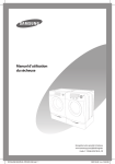
Door Reversal
1. Unplug power cord.
6. Place the door on the other
side and reattach it to dryer.
2. Remove two door hinge
screws.
3. Lift the door and remove
from
dryer.
4. Remove two screws on the
opposite side of door hinge.
7. Reassemble holder lever.
5. Remove two screws on holder
lever.
8. Reassemble the screws in
the
remaining holes.
1-16
51#SURGXFW#VSHFLILFDWLRQV
5041#WKH#IHDWXUH#RI#SURGXFW
Concept
- Super Size Capacity
- Energy Saving
- Time Saving
Main Feature
- 7.3 cu.ft.
- Energy Saving(3200 Wh/Cycle)
- Time Saving (Normal Course 44 min.)
Sub. Feature
- Fuzzy Algorithm
- Easy Reversible Door
- Slanted control panel
2-1
5051#VSHFLILFDWLRQV#RI#SURGXFW
ZDVK#W\SH
IURQW#ORDGLQJ#W\SH
Div
Inches (cm)
Div
Inches (cm)
A. Height
38”(96.5)
C. Depth with
door open 90°
49”(124.5)
B. Width
27”(68.6)
D. Depth
30.25” (77.0)
GLPHQVLRQ
ZHLJKW
56.8kg
KHDWHU#UDWLQJ
5300W
NO HEAT
268W
HEATING
5445W
SRZHU#FRQVXPSWLRQ
2-2
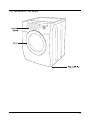
5061#RYHUYLHZ#RI#WKH#GU\HU
2-3
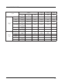
5071#WKH#FRPSDUDWLYH#VSHFLILFDWLRQV#RI#SURGXFW
Ghvljq
2-4
Prgho
DV316LG
Fdsdflw|
7.3
7.3
Grru#W|sh
Glass Transparent
Glass Transparent
Frontier Dryer
Yhqw#H{kdxvw
E/G, 3 way
E/G, 3 way
Khdwlqj#Hohphqw#+NZ,
5300W / 22,000 BTU/hr
5300W / 22,000 BTU/hr
Yrowdjh#2#Iuhtxhqf|
240V/60Hz
240V/60Hz
&#ri#Gu|lqj#F|foh
9
9
Qrupdo
Yes
Yes
Khdy|#Gxw|
Yes
Yes
Wrzhov
Yes
Yes
Shup#Suhvv
Yes
Yes
Gholfdwhv
Yes
Yes
Iuhvkhq#Xs
Yes
Yes
Wlph#Gu|
Yes
Yes
Zulqnoh#Uhohdvh
Yes
Yes
Dlu#Ioxii
Yes
Yes
&#ri#Rswlrq
3
3
P|#F|foh
Yes
Yes
Udfn#Gu|
Yes
Yes
Zulqnoh#Suhyhqw
Yes
Yes
&#ri##Whps#Ohyho
5
5
Kljk
Yes
Yes
Phglxp
Yes
Yes
Phglxp#Orz
Yes
Yes
Orz
Yes
Yes
H{wud#Orz
Yes
Yes
&#ri#Gu|qhvv#Ohyho
5
5
Yhu|#Gu|
Yes
Yes
Pruh#Gu|
Yes
Yes
Qrupdo#Gu|
Yes
Yes
Gdps#Gu|
Yes
Yes
Vrxqg#Ohyho
Louder/Softer/Off
Louder/Softer/Off
Dgmxvw#Wlph
Up/Down
Up/Down
Glphqvlrq#+K#{#Z#{#G,
38” x 27 x 31
38” x 27 x 31
5071#RSWLRQ#VSHFLILFDWLRQV
Lwhp
Lwhp#Qdph
FRGH1QR
MANUAL-BOOK
DC68-02312A
DIE-RACK DRY
DC61-01522A
Uhpdun
2-5
Memo
2-6
61#RSHUUDWLQJ#LQVWDOODWLRQV#DQG#LQVWDOODWLRQ
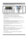
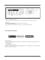
6041#RYHUYLHZ#RI#WKH#FRQWURO#SDQHO
1. Digital Graphic Display
The display window shows the estimated time remaining in the cycle after the Cycle Selector dial is
pressed. The estimated time remaining may fluctuate as the cycle progresses.
The Drying light will illuminate and remain lit until the cycle is complete.
When your dryer is in the cool-down phase, the Cooling light will illuminate.
When your dryer is in the wrinkle prevent phase, the Wrinkle Prevent light will illuminate.
When the cycle is complete, “END” will appear in the display panel until the dryer door is opened or
Power key is pushed.
If your dryer is paused during a cycle, the indicator lights will blink until the Cycle Selector dial is
pressed.
2. Dry Level Selection Button
To select the dry level in the Normal, Heavy Duty, or other Sensor Dry cycles, press the Dry Level
button. An indicator light will illuminate next to the desired dryness level.
Press the button repeatedly to scroll through the settings. Larger or bulkier loads may require the
Very Dry (select models) or More Dry setting for complete dryness.
The Less Dry setting is best suited for lightweight fabrics or for leaving some moisture in the clothing
at the end of the cycle. Damp Dry (select models) is designed to partially dry items.
Use for items that lay flat or hang to dry.
3. Temp Selection Button
To select the correct temperature for the load, press the Temp button. An indicator light will
illuminate next to the desired temperature. Press the button repeatedly to scroll through the
settings.
Kljk – For sturdy cottons or those labeled Tumble Dry.
Phglxp – For permanent press, synthetics, lightweight cottons, or items labeled Tumble Dry Medium.
Phglxp#Orz – For lower heat than Medium to dry synthetic or washable knit fabrics.
Orz#– For heat sensitive items labeled Tumble Dry Low or Tumble Dry Warm.
H{wud#Orz – Provides the lowest heated dry temperature possible.
4. Time Selection Button
When using Manual Dry cycles, time can be adjusted by pressing time selection button.
During the Sensory Dry cycle, the time light indicator is off because exact drying times are
determined by fluctuating humidity levels.
3-1
5. Signal Selection Button
When the cycle is complete, a chime will sound.
When the Wrinkle Prevent option is selected, the chime will sound intermittently.
Adjust the volume of the chime or turn it off by pressing the Signal button.
Press the button repeatedly to scroll through the choices.
6. Wrinkle Prevent Selection Button
Wrinkle Prevent provides approximately 90 minutes of intermittent tumbling in unheated air at the
end of the cycle to reduce wrinkling. Press the Wrinkle Prevent button to activate this feature.
The indicator light above the pad will illuminate when Wrinkle Prevent is selected.
Chasing lights appear in the display when the Wrinkle Prevent option is selected. The load is dry, and
can be removed at any time during the Wrinkle Prevent cycle.
7. Select Cycle Option
Adjust Time – Time can be added or subtracted from the automatically set times in the Manual
Dry cycles (Time Dry, Freshen Up, Delicates, Wrinkle Release, or Air Fluff cycles).
To add or subtract time from the cycle, press the Adjust Time arrow pad up or down until the desired
time is displayed.
My Cycle – Choose your favorite cycle including cycle, temp, dry level option, etc.
Rack Dry – Rack Dry is available at Time Dry cycle. Temperature will be set only to Extra Low.
8. Cycle Selector
To select a cycle, rotate the Cycle Selector dial to the desired cycle.
The indicator light by the cycle name will illuminate. The Normal, Heavy Duty, Towels, Perm Press and
Delicates cycles are Sensor Dry cycles.
Sensor Dry automatically senses the moisture in the load and shuts the dryer off when the selected
dryness level (very dry to damp dry) is reached.
Qrupdo – Dry loads such as cotton, underwear, and linens use this cycle to get various levels of heat
for drying.
Khdy|#Gxw| – Use this cycle to get high heat for heavy fabrics such as jeans, corduroys, or work
clothes.
Wrzhov – Dry loads such as bath towels.
Shup#Suhvv – Dry wrinkle-free cottons, synthetic fabrics, knits, and permanent press fabrics
automatically. The cycle minimizes wrinkling by providing a longer unheated cool-down
period at the end of the cycle.
Gholfdwhv – The Delicates cycle is designed to dry heat-sensitive items at a low drying temperature.
Iuhvkhq#Xs – This cycle removes odors and freshens garments.
Wlph#Gu| – Time Dry allows you to select the desired cycle time in minutes.
Turn the Cycle Selector dial to Time Dry, then press the Adjust Time up arrow to set the drying time.
Press the arrow repeatedly to scroll through the time settings.
Wrinkle Release – The Wrinkle Release cycle will release wrinkles from items that are clean, dry,
and only slightly wrinkled, such as clothes from a crowded closet, suitcase or items that have been
in the dryer too long after the cycle has ended. Wrinkle Release can be used with any temperature
selection.
Dlu#Ioxii – The Air Fluff cycle tumbles the load in room temperature air.
9. Start/Pause Selection Button
Press to pause and restart programs.
10. Power Button
Press once to turn your dryer on, press again to turn it off. If your dryer is left on for more than 10
minutes without any buttons being touched, the power automatically turns off.
3-2
6051#F\FOH#FKDUW
Default
Cycle
Sensor
Dry
Manual
Dry
Drying
Cooling
Wrinkle
prevent
Temp control
Sensor dry
level
Time
Time
Time
Time
Normal
High
(Medium)
Normal dry
44 min
39 min
5 min
90 min
Heavy
Duty
High (No
change)
Normal dry
60 min
55 min
5 min
90 min
Towels
High (Medium)
Normal dry
52 min
47 min
5 min
90 min
Perm Press
Medium
Low
(No change)
Normal dry
34 min
24 min
10 min
90 min
Delicates
Low (No
change)
Normal dry
29 min
24 min
5 min
90 min
Extra
Delicates
Extra Low
(No change)
Normal dry
29 min
24 min
5 min
90 min
Freshen Up
High (No
change)
-
30 min
25 min
5 min
-
Time Dry
High
-
40 min
35 min
5 min
-
Wrinkle
Release
Medium
-
25 min
20 min
5 min
-
Air Fluff
- (No
change)
-
20 min
-
20 min
-
Quick Dry
High
-
30 min
25 min
5 min
-
3-3
6061#PDLQ#IXQFWLRQ
FKLOG#ORFN
A function to prevent children from playing with your dryer.
VHWWLQJ2UHOHDVLQJ
If you want to set or release Child Lock, press both the Time and Signal buttons at the same time for 3
seconds.
How to Set:
1. It can be set while your dryer is running.
2. Once you set the Child Lock function, no button, except for the Power button,
can be controlled until you release the Child Lock function.
3. The Child Lock indicator will be lit.
Notice:
1. If the power is on again, the Child Lock function remains unchanged.
2. To release that function, follow the instructions above.
Notice:
When other buttons, except for the Power button, do not respond, check the Child Lock indicator.
P\#F\FOH
Lets you activate your customized cycle that includes Dry Level, Temp, Time option, etc.
By pushing the My Cycle button, you activate the settings used during the previous My Cycle mode.
(Default : Normal Cycle)
If My Cycle mode is activated, My Cycle button will be lit.
You can select all options in My Cycle mode as follows.
1. Select cycle using Cycle Selector dial.
2. After cycle selection, set each option.
Note: At this time, the option will follow as per each cycle’s default option selection.
Then you can start My Cycle by pushing the Start/Pause button in My Cycle mode.
The cycle and options you select will be displayed next time you choose My Cycle.
3-4
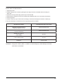
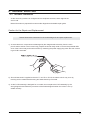
Udfn#Gu|
INSTALLING THE DRYING RACK
1. Open dryer door.
2. Position drying rack in tumbler, placing the rear legs in the two recessed areas of the dryer’s
back wall.
3. Place the front lip of the drying rack on top of the lint filter.
4. Place items to be dried on the rack, leaving space between them so air can reach all surfaces.
5. Close dryer door.
6. Use the Time Dry cycle. Select time according to moisture and weight of the items. Start dryer.
It may be necessary to reset the timer if a longer drying time is needed.
SUGGESTED ITEMS
SUGGESTED TEMP. SETTINGS
Washable sweaters (block to
shape and lay flat on rack)
Heat (Low/Extra Low)
Stuffed toys (cotton or
polyester fiberfilled)
Heat (Low/Extra Low)
Stuffed toys (foam or
rubber-filled)
Air Fluff
Foam rubber pillows
Air Fluff
Sneakers
Fluff or Heat
WARNING – Drying foam rubber, plastic, or rubber on a heat setting may cause damage to the item
and lead to a fire hazard.
3-5
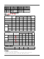
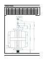
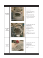
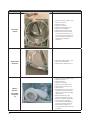
6071#GHVLJQDWLRQ#RI#PDLQ#FRPSRQHQWV
607041#Khdwhu
3-6
607051#Prwru
ڕ ڭڪگڪڨ
ەڣڋڑ ڱڋڍڌ
ۏێۀگ ڿڼۊڧ ۊک ډڌ
−
ڄۀڿۄێ ۔ۀۇۇېګڃڲډڞډڞ
X
ۀۂڿېڥ
ڞڠګڮ
ڲډڞ
ڎپ
ڍپ
ڌپ
ۈۀۏڤ
ڮڮڜګ
ڒډڋڑڌ
ړڐڌ
ڐڑڌ
ڋډڔڐڌ
ڋڔڌ
ڄڲڃۍۀےۊګ ۏېۋۉڤ
ڮڮڜګ
ڏڏڎډڏ
ڔړڍډڏ
ڐڒڎډڏ
ڒڑڎډڏ
ڔډڏ
ڄڜڃۏۉۀۍۍېڞ ۏېۋۉڤ
ڮڮڜګ
ڏړڒڌ
ڏړڒڌ
ڏړڒڌ
ڐړڒڌ
ڋڐڒڌ
ڨګڭ
ڮڮڜګ
ڎڋډڔڏ
ڎډڔڏ
ڒډړڏ
ڌډڔڏ
ڋڐ
ڄڝڿڃۀێۄۊک
ڮڮڜګ
ڋډڍڍ
ڍڍ
ڎڍ
ڌڍ
ڋڐ
ڄڱڃۀۂڼۏۇۊڱ ۂۉۄۏۍڼۏڮ
ڮڮڜګ
ڋډڌڌڎڌ
ڋڌڎڌ
ڐڌڎڌ
ڔڋڎڌ
ۈۋۍڐڒڋڐڎڌ
ۀێۊۇھ
ۇڼۂېہۄۍۏۉۀڞ
ڮڮڜګ
ڋډڒڐړ
ڏڑړ
ڋڐړ
ڒڐړ
ۈۋۍڋڋڌڋڒړ
ۉۀۋۊ
ۃھۏۄےڮ
ڮڮڜګ
ڒډڒڍڏڏ
ڋډڏڔڏڏ
ڋډړڎڎڏ
ڋډڌڐڏڏ
ڋڋڋڐ
ڄڲڃۍۀےۊګ ۏېۋۉڤ
ڮڮڜګ
ڋڏڒډڋڏ
ڋڍڐډڌڏ
ڋڒڒډڔڎ
ڋڎڔډڋڏ
ڑڏ
ڮڮڜګ
ڦڪ
ڈ
ڈ
ڦڪ
ۇڼۈۍۊک
ۏېۋۉڤ
ڄڜڃۏۉۀۍۍېڞ
ۇڼۈۍۊۉڽڜ
ڭڪگڞڠگڪڭګ
ۏێۀگ ڿڼۊڧ ڿۀۏڼڭ ډڍ
−
ۍۀ۔ۍڟ
X
ۀۂڿېڥ
ڄڣڮڜڲڃڞڠګڮ
ۃێڼڲ
ڎپ
ڍپ
ڌپ
ۈۀۏڤ
ڮڮڜګ
ڍډڍڏڎ
ڋډڋڏڎ
ڒډڏڐڎ
ڋډڍڎڎ
ڋڋڏ
ڄڲڃۍۀےۊګ ۏېۋۉڤ
ڮڮڜګ
ڌڋڏډڏ
ړړڎډڏ
ړڐڏډڏ
ڒڐڎډڏ
ڋډڐ
ڄڜڃۏۉۀۍۍېڞ ۏېۋۉڤ
ڮڮڜګ
ڔڏڌڐ
ڒڏڌڐ
ڋڐڌڐ
ڔڏڌڐ
ڋڋڒڐ
ڄڲڃۍۀےۊګ ۏېۋۉڤ
ڮڮڜګ
ڏڐډڌڍ
ڎڐډڌڍ
ڏڐډڌڍ
ڏڐډڌڍ
ڏڍ
ڄڜڃۏۉۀۍۍېڞ ۏېۋۉڤ
ڮڮڜګ
ڏڑډڏڍ
ڍڑډڏڍ
ڍڒډڏڍ
ڒڐډڏڍ
ڒڍ
ڄڜڃۏۉۀۍۍېڞ ۏېۋۉڤ
ڮڮڜګ
ڑډړڏ
ڑډړڏ
ڒډړڏ
ڐډړڏ
ڎ ڔڏ
ڨګڭںڨڰڭڟ
ڮڮڜګ
ڎډڎړ
ڎړ
ڍړ
ڐړ
ۂۀڿڐڔ
ڧڰںڄۂۀڿڃۀێۄڭ ۀۍېۏڼۍۀۋۈۀگ
ڮڮڜګ
ڎډڔړ
ڔړ
ڌڔ
ړړ
ۂۀڿڐڔ
ڞڠڤںڄۂۀڿڃۀێۄڭ ۀۍېۏڼۍۀۋۈۀگ
ۍۊۏۊڨ
ۍۀۏڼۀڣ
ۇڼۏۊگ
ۉۊۄۏھۀۋێۉڤ ۀۇڽۈۀێێڼێۄڟ ډڎ
ۏۉۀۈۂڿېڥ
ڎپ
ڍپ
ڌپ
ۈۀۏۄ
ڮڮڜګ
ڦڪ
ڦڪ
ڦڪ
ۏێۀۏ ۇڼۈۍۊۉ ۏۍڼۋ ۃھڼۀ
ۀھۉۀۍۀہۀڭ ډڏ
کڪڤگڤڟکڪڞ ۏێۀۏ ۂۉۄێۄۍ ۀۍېۏڼۍۀۋۈۀۏ ڌڈڏ
ڄۀۇھ۔ھڎ ڇ༌ڍډڒ ۇۀےۊۏ ڇۈڋڑ ۔ۍڿ ۀۈۄگ ڇ۔ھۉۀېیۀۍڡ ڿۀۏڼڭ ڇڄڱڃڑڋډڌڅۀۂڼۏۇۊۑ ڿۀۏڼڭڃڞڠڤڕ
ڄۀۇھ۔ھڎ ڇ༌ڑډڑ ۇۀےۊۏ ڇۈڋڑ ۔ۍڿ ۀۈۄگ ڇ۔ھۉۀېیۀۍڡ ڿۀۏڼڭ ڇۀۂڼۏۇۊۑ ڿۀۏڼڭڃڧڰڕ
3-7
ۉۊۄێۉۀۈۄڟ ۇڼھۄۉڼۃھۀڨ ډڐ
ͥͩͣ͟͢͟ρͤ͟͢͡ ͩͣͥ͢͟ρ
ͨͣ͟͢
͚͙͑͢͟͜͡͡͞͡
͢͟͢͡͡
͚͙͑ͦ͢͟͟͜͡͞͡͡
ͪͩͦͦ͟͡ρ
ͪͩͨͥͧ͟͢͟͡ρͦͨ͢͟ ͣͥͨ͟ρͩͪ͟͡ ͥ͟͡͡ρ
ΤΡΖΔ
ͦͪ͢͟͢
ͨͥͣͩ͟
ͪͩͧͣ͟͢
ͥ͟͢͡͡͡
ͥͦͦ͢͟
ͧͥ͢͟͡
ͧͧͥͣ͟
ͥͥͨ͟͢͡
͢
ͣͧͩ͟͢
ͨͨͣͩ͟
ͨͩͧͣ͟͢
ͤ͢͟͢͡͡
ͤͩͥͦ͟
ͧͥ͟͡͡
ͧͥͥͣ͟
ͧͧͥͨ͟͢
ͣ
ͤͪ͟͢͡
ͣͣͣͩ͟
ͩͩͧͣ͟͢
ͦͪͪͪ͟
ͩͩͥͦ͟
ͧͥ͢͟͡
ͪͧͥͣ͟
ͥͣͥͨ͟͢
ͤ
ͨͦͩ͟͢
ͤͤͣͩ͟
ͩͩͧͣ͟͢
ͪͥ͟͢͡͡
ͣͩͥͦ͟
ͨͥ͢͟͡
ͦͥͣ͢͟
ͪͧͥͨ͟͢
ͥ
ͪͩͩ͟͢
ͦͣͣͩ͟
ͨͩͧͣ͟͢
ͨͦ͟͢͡͡
ͤͪͥͦ͟
ͩͥ͟͡͡
ͧͥͣ͟͡
ͥͤͥͨ͟͢
ͦ
3-8
71#DOLJQPHQW#DQG#DGMXVWPHQWV
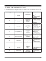
7041#HUURU#LWHPV#DQG#GLDJQRVWLF#FRGHV
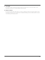
1.
An occurrence of an Error will make a sound of error melody for 5sec and continuously show one of the
Error Displays from the following errors.
Display
tS
tO
do
FE
dF
Description
Trigger
Action Taken
The Thermistor
resistance is
very low.
Check for:
- Clogged lint screen.
- Restricted vent system.
- Check Thermistor
resistance.
The Thermistor
resistance is
very high.
Check for:
- Clogged lint screen.
- Restricted vent system.
- Check Thermistor
resistance.
Running the
dryer with door
open
Check for:
- Close the door, and
run the dryer
- Loose or open wire
terminals in Door
Sense circuit.
Power source frequency Error
Invalid power
source
Frequency
Check for:
- Not using regular
power source
frequency
- Invalid power frequency sense circuit
Door Circuit Failure
Invalid state for more
than 256
milliseconds
Check for:
- Loose or open wire
terminals in Door
Sense circuit.
Check for:
- Restricted vent system.
- Check Thermistor
resistance.
Dryer Thermistor Short
Sensed
Dryer Thermistor Open
Sensed
Door Open
hE
Heater Error
Invalid heating Temp in
running the dryer
bE
Button Error
Invalid state
of key circuit short
for 75secs
od
Over Dry
Invalid Dry
time in
excess Dry time
Check for:
- Sensor bar Open
- using Adjust time Up
excessively
Et
EEprom Fail
Invalid state
of Eeprom
communication
Check for
- PCB on EEprom
circuit
Check for:
- Display PCB key
circuit short or not
4-1
4-2. TEST MODE
4-2-1. Continuous Run Mode
Continuous Run Mode:
1. Press Signal + Dryness Level for 3 sec during Power On State (Normal User Mode) .
2. Once in Continuous Run Mode, 7-Segment will toggle display “cc” and the remaining time.
3. The previous cycle will restart during Continuous Run Mode until continuous run mode is
disabled.
4. During Continuous Run Mode, press Signal + Dryness Level for 3 seconds to return to normal
user mode. 7-segment will no long display “cc” and only display the remaining time.
4-2-2. Special Test Mode
Definition of Special Test Mode:
- Dryer must be on before Service Mode can be entered.
- Press Signal and Temp Keys for 3 seconds, or until 3 beeps are heard.
- The machine will now be in Service Mode.
- Upon entry into Service Mode, the Sensor Bar Touch Data will be shown (Default Special Test Mode).
How to Enter:
- To enter Special Test Mode press Signal and Temp Keys for 3 seconds for 3 seconds or until the control
beep.
(same for all Frontier models.)
4-2
4-2-3. Sensor Bar Touch Data Mode
Definition of Sensor Bar Touch Data Mode:
-While in Power On pressing Signal and Temp Keys for 3 seconds
-This action will put the dryer into sensor bar touch data mode
- Dryer will display Sensor Bar data. This mode is default mode of entering service mode
How to Enter:
- While in Power off pressing Signal and Temp Keys for 3 seconds (same for all Frontier models.)
4-2-4. Cycle Count Mode
Definition of Cycle Count Mode:
- While in Service Mode pressing the Signal key will put the dryer into the cycle count mode
- Cycle number executed will display.
How to Enter:
- To enter Special Test Mode press While in Service Mode pressing the Signal key for 3 seconds or until
the control beep.
(same for all Frontier models.)
4-3
4-2-5. Software Version Mode
Definition of Software Version Mode:
- While in Service Mode pressing the Temp key will put the dryer into the software version mode
How to Enter:
- To enter Special Test Mode press Temp Key until the control beep.
(same for all Frontier models.)
ex) In case of “U105”, U0 means major version “v1“ 05 means minor version “05”
4-2-6. System Check Mode
Special Test Mode:
- While in Power Off, pressing the Dryness Level + Power keys simultaneously will put the dryer into the
System Check mode
- “ t2 “ will display.
- System Check Mode Progress
t2 mode Function Performed Start/Pause Motor(CW) Relay On → Heater Relay On → Heater Relay Off →
Motor(CW) Relay Off (Circulation)
4-4
81#DVVHPEO\#DQG#GLVDVVHPEO\
8041#WRROV#IRU#GLVDVVHPEO\#DQG#DVVHPEO\
NO.
TOOL
1
Box driver
2
Double-ended
spanner
10mm
13mm
19mm
Heater (1)
Motor (1), Balance (5), 2 holes of each left and right of the
shock absorber 1 Pulley hole
10, 13,19mm
Replaceable for the box driver.
Since the bolt runs idle when the box driver is used, use the
box driver 17mm.
3
Vice pliers
4
Other(Driver, Nipper, Long nose)
5
JIG for the Tub
Tool to protect the idle and abrasion of the bolt for the
box driver.
General tools for the after service.
1 (Disassemble and Assemble)
######
5-1
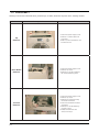
8051#GLVDVVHPEO\
Warning! To avoid risk of electrical shock, personal injury or death, disconnect the power to the washing machine.
Part Name
How To Do
Top
Removal
1.Disconnect power supply to unit.
2.Remove 2 10mm screws from
dryer back.
3.Slide Top Cover towards the rear
and lift from unit.
Drum Baffle
Removal
1.Disconnect power supply to unit.
2.Remove Top Cover.
3.Remove four screws located at
the sound dampening seem.
Console
Removal
1.Disconnect power supply to unit.
2.Remove Top Cover.
3.Remove two screws mounting
the Heater PCB Board.
4.Disconnect the black and white
connectors.
5.Remove four screws attaching
Console to dryer
6.Rotate Console down and
remove from dryer.
####
5-2
Descriptive Picture
Part Name
Descriptive Picture
How To Do
Front Panel
Removal
1.Disconnect power supply to unit.
2.Remove Top Cover.
3.Remove Console.
4.Remove four screws attaching
Front Panel to dryer.
5.Remove two screws in the door
area.
6.Pull Front Panel forward and
disconnect the Interior Light
harness.
7.Lift the Front Panel off the three
tabs across the bottom and
remove.
Front Bulkhead
Removal
1.Disconnect power supply to unit.
2.Remove Top Cover.
3.Remove Console.
4.Remove Front Panel.
5.Remove screws retaining
Console Back Cover.
6.DisconnectInteriorLightwiring
harness.
7.Disconnect Moisture Sensor
wiring harness.
8.Remove four Bulkhead retaining
screws.
9.Lift Bulkhead from Cabinet and
remove.
Moisture
Sensor
Removal
1.Disconnect power supply to unit.
2.Remove Top Cover.
3.Remove Console.
4.Remove Front Panel.
5.Disconnect Moisture Sensor wire
harness.
6.Remove sensor attachment
screw.
####
5-3
Part Name
How To Do
Drum Removal
1.Disconnect power supply to unit.
2.Remove Top Cover.
3.Remove Console.
4.Remove Front Panel.
5.Remove Console Back Cover.
6.Remove Front Bulkhead.
7.Remove belt from Idler Pulley.
8.Grasp the Drum with one hand
and the belt with the other. Lift
the Drum and slide out the front.
Carefully spread the cabinet as
needed to gain additional
clearance.
Rear Roller
Removal
1.Disconnect power supply to unit.
2.Remove Rear Bulkhead.
3.Remove Roller Keeper and nut.
Motor/
Blower
Assembly
Removal
(1)
1.Disconnect power supply to unit.
2.Remove Top Cover.
3.Remove Console.
4.Remove Front Panel.
5.Remove Console Back Cover.
6.Remove Belt from Idler Pulley.
7.Remove Drum.
8.Remove the two screws securing
the Blower Intake Panel to the
Blower Housing. Remove Blower
Intake panel.
9.Removed the screw at the
bottom of the blower housing.
10.Remove the blower attachment
screw under the Thermistor.
11.Remove two screws attaching
the motor bracket to the base.
12.Disconnect the Motor wire
harness and the two wires to the
belt switch.
####
5-4
Descriptive Picture
Part Name
Motor/Blower
Assembly
Removal
(2)
Descriptive Picture
How To Do
13.Slide the Motor Blower.
Assembly toward the heater and
lift to disengage the tabs on the motor
from the slots in the base.
14.Remove the 14mm nut securing the blower
wheel to the shaft. The nut is a left hand
thread.
QRWH=#D#zuhqfk#fdq#eh#sodfhg#rq#erwk##
# # hqgv#ri#wkh#Prwru#Rxwsxw#Vkdiw1
15.Remove Blower Wheel.
16.Remove the three screws
securing the blower housing to
the motor bracket.
17.Remove the three screws
securing the blower housing to
the motor bracket .
18.Use a wide blade screwdriver to pop off the
motor retentionclamps.
Rear Bulkhead
Removal
1.Disconnect power supply to unit.
2.Remove Top Cover.
3.Remove Console.
4.Remove Front Panel.
5.Remove Console Back Cover.
6.Remove Belt from Idler Pulley.
7.Remove Drum.
8.Remove 7 screws from the back.
9.Lift the rear bulkhead off the right
and left side hangers.
Burner Removal
1.Disconnect power supply to unit.
2.Shut off gas supply.
3.Disconnect gas line.
4.Remove two screws securing
burner to bracket.
QRWH=#Wkh#Ljqlwhu#Edu#lv#iudjloh1#Eh#
# #
fduhixo#qrw#wr#gdpdjh#Ljqlwhu#zkhq##
# #
uhprylqj#Exuqhu#Dvvhpeo|1
5.Remove the two screws attaching
the housing to the burner bracket.
The screws are recessed from view.
6.Slide Burner Assembly from dryer.
Heater Assembly
Removal
1.Disconnect power supply to unit.
2.Remove Top Cover.
3.Remove Console.
4.Remove Front Cover.
5.Remove Heater Assembly retaining screw.
6.Slide Heater Assembly out the front of dryer.
7.Remove the wiring terminals from the Heater
Assembly.
8.Reinstall by aligning the tabs on the back
bulkhead with the notches in the Heater As
sembly.
####
5-5
8061#UHDVVHPEO\
Reassembly procedures are in the reverse order of dissasembly procedures.
5-6
91#WURXEOH#VKRRWLQJ
9041#WURXEOH#GLDJQRVLV
-
As the micom dry machine is configured of the complicate structure, there might be the
service call.
Below information is prepared for exact trouble diagnosis and suitable repair guide.
Caution for the Repair and Replacement
Please follow below instruction for the trouble diagnosis and parts replacement.
1) As some electronic components are damaged by the charged static electricity from the resin
part of wash machine or the human body, prepare the human body earth or remove the potential differ
ence of the human body and wash machine by contacting the power supply plug when the work contact
ing to PCB is executed.
2) Since AC220~240V is applied to the triac T1 and T2 on P.C.B, the electric shock may occur by
touching and be careful that the strong and weak electricity are mixed.
3) As the P.C.B assembly is designed for no trouble, do not replace the P.C.B assembly by the
wrong diagnosis and follow the procedure of the trouble diagnosis when the micom is not op
erated normally.
6-1
No
Problem
What To Do
Will Not Start or Run
• All wires are hooked up to their corresponding terminals.
• Dryer is plugged in.
• Blown fuse or circuit breaker.
• Door switch functional...door closed. Check for error code 3 (See Table for code
definition).
• Start/Pause rotary selector dial functional.
• Control Board operational.
• Belt off or broken and Belt Cut-off Switch operates.
• Drive motor functional.
• Check motor winding resistance: 2.88ohms between pin #3 and 4, 3.5ohms
between pin #4 and 5.
2
Motor runs/ tumbler will not turn
• Belt off or broken/damaged.
• Idler tension spring too weak or stretched.
• Idler pulley jammed or stuck.
3
Runs a few minutes and then
stops
• Lint buildup around drive motor.
• Low voltage present.
• Blower impeller blocked in blower housing.
• Drive motor - start switch contacts stuck closed.
4
Blows fuses or trips circuit
breaker
- Is the belt connected well?
- Is the winding of the motor continuous?
(Rotor winding, stator winding, generator)
- Is the motor protector normal?
• If above points are not found, the PCB assembly is out of order.
Replace it.
5
Blows fuses or trips circuit
breaker
(Gas Model)
• During ignition the dryer will draw X amps. With the burner ON, the dryer will
draw X amps. If the dryer is drawing amperages above this, then the house
wiring, fuse box or circuit breaker is suspected to be at fault.
• Igniter harness loose and shorted to base.
• Incorrect wiring or wire shorted to ground.
• Drive motor winding shorting to ground.
6
Will not heat (motor runs)
Open heating element.
• Hi-Limit trips easily or is open.
• Regulating thermostat trips easily or is open.
• Membrane switch open.
• Check Thermistor.
7
Will Not Dry Gas Model
Poor Gas Ignition
When the dryer is operated on a heat setting, the igniter should be energized and
burner shall fire within 45 seconds at 120 VAC. The failure of a component in this
system will usually be indicated by one of three symptoms:
The igniter does not glow
If the igniter does not heat up, remove power and using an ohmmeter, check the
following:
• Open flame sensor
• Open igniter
• Shorted booster coil
• Open wiring
• Bad motor switch ( Neutral supply)
• No power from control ( L1 supply)
Igniter glows - No gas ignition
If the igniter heats up but the main burner flame is not ignited, remove power and
using an ohmmeter, check the following:
• Open secondary coil
• Open holding coil
• Open wire harness
• Stuck flame sensor (Stuck closed)
The gas is ignited but the flame
goes out
If a normal ignition takes place and after a short while the flame goes out, check
for the following:
• Radiant sensor contacts opening prematurely.
• Weak gas valve coil may open when stressed by higher Temps.
• Weak Hi-Limit
• Poor venting
• Bad drum seals
Improper drying
clothes wrinkled
Rough texture
long dry time
• Lint filter is not clean.
• Restriction in exhaust.
• Outside exhaust hood damper door stuck closed.
• Exhaust too long, too many elbows, flex ductwork installed.
• Poor intake air available for the dryer.
• Incorrect tumbler speed. Tumbler belt slipping.
• Blower impeller bound; check for foreign material in blower area.
• Customer overloading dryer.
• Check clothing labels for fabric content and cycle selected.
• Clothes too wet due to insufficient spin out by washer.
Noisy and/Or Vibration
• Thumping Check for loose tumbler baffle, rear tumbler roller(s) worn or
misaligned, out-of-round tumbler or high weld seam on tumbler.
• Ticking Check for loose wire harness or object caught in blower wheel area.
• Scraping Check for front or rear bulkhead felt seal out of position or worn
tumbler front bearings.
• Roaring Check for blower wheel rubbing on blower housing or bad motor
bearings.
• Popping or squealing sound. Check for a sticky or frayed belt.
1
8
9
10
11
12
6-2
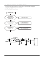
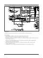
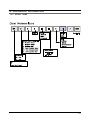
9051#SUREOHP#FKHFNLQJ#DQG#PHWKRG#RI#SFE
-If you plug in the power cord and turn Power S/W on, memorized data is displayed.
If any data is not displayed, check the followings.
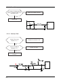
90504#Wkh#Sduw#Ri#Srzhu#Vrxufh#
No Power ON
The Voltage Of
Betweenⓐand ⓑIs
As Big As 12V?
No
Check The Trans
Yes
The Voltage Of
Betweenⓒand ⓓ Is
As Big As 12V?
No
Check The Diode
(D11,D12,D16,D17,D18)
And Condenser(CE3)
No
Exchange IC3(7805) And Check
The Condenser(CE5)
Yes
The Voltage Of
Betweenⓔand ⓓ Is
As Big As 5V?
Yes
6-3
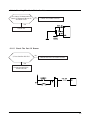
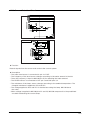
905051#Uhvhw#Sduw
The Value Of Measurement
Result Of Between Micom 25
And Gnd Is 5V?
No
Check The Power Source
Yes
Check IC4
IC4
7533
R40 100
25
CE7 1UF
905061#Lqwhuuxsw#Sduw
Check The Curve
Output Of ⓐ ?
Check D11,12,16,17,18
Yes
Check The Micom
Number 67 ?
Yes
Check The Part Of
Oscillator
6-4
Check TR2,R35
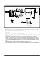
905071#Fkhfnlqj#Wkh#Sduw#Ri#Dq#Rvfloodwru
The Value Of Measurement
Result Of Between Micom 25
And Gnd Is 5V?
No
Check The Power Source
Yes
Check IC4
905081#Fkhfn#Wkh#Sduw#Ri#Ex}}hu
ⓐ Part Confirm DC12V ?
No
Check The Part Of Power Source
Yes
Exchange BUZZER1,
Check R5,R46
6-5
Memo
6-6
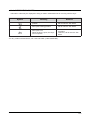
7. EXPLODED VIEW AND PARTS LIST
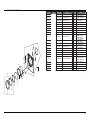
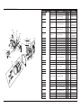
7-1. EXPLODED VIEW OF FRAME, PANEL-CONTROL
Y0161
Z0050 Z0050
A0367
U0363
A0364
N0006
Y0162
Z0019
Z0050
P0001
Z0006
C0002
C0082
C0108
F0125
C0029
C0105
A0282
Z0007
C0044
A0364
M0066
P0170
Z0050
A0370
W0002
F0028
F0229
N0006
Z0007
B0070
W0037
W0001
Z0007
W0004
B0075
B0074
7-1
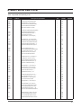
Location No.
7-2
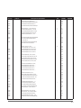
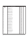
Code No.
DESCRIPTION
SPECIFICATION
QTY SA/SNA
REMARK
A0282
DC63-00534B COVER-BACK
WINGS-DRYER,SGCC(GI),T0.8
1
SA
A0364
DC61-60074A CLAMPER-WIRE SADDLE
NYLON#66(DAWS-6NB)
3
SA
A0367
DC61-01229A HOLDER-PCB
WINGS-DRYER,SECC(EGI),T0.8,
1
SA
A0370
DC97-07519A ASSY-DUCT EXHAUST
MDE7800AYW,DRYER
1
SA
B0070
DC97-07514A ASSY-LEG
MDE9700AYW,DRYER/MAYTAG
4
SA
B0074
DC61-01212A LEG
WINGS-PROJECT,FRPP
1
SA
B0075
DC61-01226A BRACKET-LEG
WINGS-DRYER,SECC(EGI),T1.6
1
SA
C0029
DC97-10526A ASSY-KNOB ENCODER
FRONTIER,BBY
1
SA
C0029
DC97-10511A ASSY-KNOB ENCODER
FRONTIER,LOWES
1
SA
C0044
DC64-01105A BUTTON-PUSH(P)
WF326LAW,ABS,WHT,FRON
1
SA
C0044
DC64-01105C BUTTON-PUSH(P)
WF316BAC,ABS,SILKY CH
1
SA
C0044
DC64-01105B BUTTON-PUSH(P)
WF326LAS,ABS,IMPERIAL
1
SA
C0082
DC64-01122A PANEL-CONTROL
DV736E4/XAA,ABS,WH
1
SNA
C0082
DC64-01122C PANEL-CONTROL
DV316BEC/XAA,ABS,W
1
SNA
C0082
DC64-01122B PANEL-CONTROL
DV316LGS/XAA,ABS,W
1
SNA
C0105
DC64-01132A BUTTON-ENCODER
WF-G126,ABS,WHT,FRONT
1
SA
C0105
DC64-01108A BUTTON-ENCODER
WF326LAW,ABS,WHT,FRON
1
SA
C0105
DC64-01132C BUTTON-ENCODER
WF316BAC,ABS,SILKY CH
1
SA
DV316LES, DV316LGS
DV3C6BEW, DV3C6BGW
DV316BEW, DV316BGW
DV316LGW, DV316LEW
DV306LEW, DV306LGW
DV316BEC, DV316BGC
C0105
DC64-01108B BUTTON-ENCODER
WF326LAS,ABS,IMPERIAL
1
SA
DV316LES, DV316LGS
C0108
DC66-00413A LEVER-POWER
1
SA
F0028
DC97-07516B ASSY-FRAME
1
SA
F0028
DC97-07516A ASSY-FRAME
1
SA
F0028
DC97-07516H ASSY-FRAME
GW-PJT,POM,NTR,ENTRY
MDG9700AWW,MAYTAG/PREMIUM/
GAS
MDE7800AYW,MAYTAG/PREMIUM/
WHT
DV316BGC/XAA,FRONTIER/GAS/BBY
1
SA
DV316LGW, DV3C6BGW
DV316BGW, DV306LGW
DV316LEW, DV3C6BEW
DV316BEW, DV306LEW
DV316BGC
F0028
DC97-07516G ASSY-FRAME
DV316BEC/XAA,FRONTIER/GAS/BBY
1
SA
DV316BEC
F0028
DC97-07516F ASSY-FRAME
DV316LGS/XAA,FRONTIER/GAS
1
SA
DV316LGS
DV316LES
F0028
DC97-07516E ASSY-FRAME
DV316LES/XAA,FRONTIER/GAS
1
SNA
F0065
DC97-10912A ASSY-FRAME PLATE(U)
DV316LGW/XAA,FRONTIE
1
SNA
F0229
DC61-01233A GUIDE-EXHAUST
WINGS-DRYER,SECC(EGI),T0.8
1
SA
M0066
DC61-01522A DIE-RACK DRY
WINGS-DRYER,TB-54,NTR,P
1
SA
N0006
DC61-40081A HOLDER-WIRE
DAWH-2NC,NYLON66,NTR
13
SA
DV3C6BEW, DV3C6BGW
DV316BEC, DV316BGC
DV316BEW, DV316BGW
DV316LGW, DV316LEW
DV306LEW, DV306LGW
DV316LES,DV316LGS
DV316LGW, DV316LEW
DV3C6BEW, DV3C6BGW
DV316BEW, DV316BGW
DV306LEW, DV306LGW
DV316BEC, DV316BGC
DV316LES, DV316LGS
DV316LGW, DV316LEW
DV3C6BEW, DV3C6BGW
DV316BEW, DV316BGW
DV306LEW, DV306LGW
DV316BEC, DV316BGC
FRONTIER,DRYER
1
SNA
DC97-08634H ASSY-COVER TOP
FRONTIER,DRY_SILKY-CHAMPA
1
SNA
DV316LGW, DV316LEW
DV3C6BEW, DV3C6BGW
DV316BEW, DV316BGW
DV306LEW, DV306LGW
DV316BEC, DV316BGC
DC97-08634G ASSY-COVER TOP
FRONTIER,DRY_IMPERIAL-SIL
1
SNA
DV316LES, DV316LGS
P0170
DC97-08855A ASSY-COVER POWER
MDE9700AYW
1
SA
U0363
6502-000127 CABLE CLAMP
DAWH-18NB,ID15,NYLON66,NTR
1
SA
W0002
DC96-00038G ASSY POWER CORD
DV4006,EP3(16A)DRYER
1
SA
W0004
DC96-00765C ASSY-M.WIRE HARNESS
MDG9700,LAMP L1
1
SA
P0001
DC97-08634F ASSY-COVER TOP
P0001
P0001
DV316LGW, DV306LGW
DV316LGS
DV316LGW,DV316BGC
DV316BGW, DV316LGS
Location No.
Code No.
DESCRIPTION
W0004
DC96-00764C ASSY-M.WIRE HARNESS
MDE9700,LAMP/THERMAL
1
SA
W0004
DC96-00765D ASSY-M.WIRE HARNESS
MDG6700,ENTRY L1 N0
1
SA
REMARK
DV316LEW, DV316BEC
DV316BEW, DV316LES
DV3C6BGW, DV306LGW
W0004
DC96-00764D ASSY-M.WIRE HARNESS
MDE6700,NO LAMP
1
SA
DV3C6BEW, DV306LEW
W0037
DC96-00763A ASSY-FLAT WIRE HARNESS
GR-PJT,FLAT WIRE
1
SA
Y0161
MFS-FTDT-00 ASSY PCB PARTS(M)
MFS-FTDT-00
1
SA
Y0162
MFS-F12DL-S0 ASSY PCB PARTS(S)
MFS-F12DL-S0 FRONTIER
1
SA
Y0162
MFS-F12DB-S0 ASSY PCB PARTS(S)
MFS-F12DB-S0 FRONTIER
1
SA
Y0162
MFS-F13DL-S0 ASSY PCB PARTS(S)
MFS-F13DL-S0 FRONTIER
1
SA
Y0162
Z0006
Z0007
Z0019
Z0050
C0002
C0002
C0002
C0002
MFS-F13DB-S0
6002-000213
6002-000239
6006-001170
6002-000231
DC97-10866B
DC97-10866A
DC97-10866D
DC97-10866C
MFS-F13DB-S0 FRONTIER
TH,+,1,M4,L12,ZPC(YEL),S
TH,+,2S,M4,L8,ZPC(YEL),S
TH,+,WT,TC,M4,L10,ZPC(YEL)
TH,+,2S,M4,L12,ZPC(YEL),
FRONTIER(DRYER),DV3
FRONTIER(DRYER),DV3
FRONTIER(DRYER),DV3
FRONTIER(DRYER),DV3
1
12
20
1
25
1
1
1
1
SA
SNA
SC
SA
SA
SA
SA
SA
SA
ASSY PCB PARTS(S)
SCREW-TAPPING
SCREW-TAPPING
SCREW-TAPPING
SCREW-TAPPING
ASSY-S.PANEL CONTROL
ASSY-S.PANEL CONTROL
ASSY-S.PANEL CONTROL
ASSY-S.PANEL CONTROL
SPECIFICATION
QTY SA/SNA
DV316LGW, DV316LEW
DV316LES, DV316LGS
DV316BEC, DV316BGC
DV316BEW, DV316BGW
DV306LEW, DV306LGW
DV3C6BEW, DV3C6BGW
DV3C6BEW
DV316LGW
DV316BEC
DV316LES
7-2. EXPLODED VIEW OF FRONT
Location No.
Code No.
DESCRIPTION
SPECIFICATION
QTY SA/SNA
D0010
DC97-10342B
ASSY-COVER DOOR
WF316BAW,SPRAY(IMPERIAL-
1
SA
D0010
DC97-10342A
ASSY-COVER DOOR
WF-G106AW,FRONTIER
1
SA
D0010
DC97-10338A
ASSY-COVER DOOR
WF326LAW,FRONTIER
1
SA
D0048
DC61-01222A
BRACKET-HINGE
WINGS-DRYER,SECC(EGI),T1.6
2
SA
D0061
DC64-00993A
DOOR-GLASS
WINGS-DRYER,GLASS,T5,TR
1
SA
D0066
DC64-01120A
DOOR-SAFETY
WF326LAW,PET,T2.8,NTR,
1
SA
D0072
DC61-00891A
GUIDE-HINGE
HAUZEN(DOM),POM,WHT,HI
4
SA
D0081
DC61-01523A
HOLDER-GLASS
DV736E4/XAA,TB-53,GRY
1
SA
D0094
DC62-00198B
SEAL-DOOR
WINGS-DRYER,SILICON,GRY,
1
SA
D0105
DC61-01576A
SUPPORT-HINGE
FRONTIER-PJT,STS430,T1.2
1
SNA
D0105
DC61-01576B
SUPPORT-HINGE
FRONTIER-PJT,STS304,T1.2
1
SNA
D0106
DC63-00674A
COVER-DOOR
WF306LAW,ABS,T2.8,NEA
1
SA
D0106
DC63-00674B
COVER-DOOR
WF316BAW,ABS,T2.8,IMP
1
SA
D0107
DC66-00395A
LEVER-DOOR
WINGS-DRYER,POM,NTR
1
SA
D0108
DC61-01532A
HINGE-DOOR
WF326LAW,ZNDC,T3.8,FR
1
SA
D0048
F0042
D0107
D0113
Z0008
D0072
Z0008
D0113
DC97-07510B
ASSY-HOLDER LEVER MDE7800AYW,DRYER/DOOR
1
SNA
F0042
DC64-00828A
DOOR-S/W
1
SA
GD-PJT,PA,T13.6,H38.5,W44.3,
REMARK
DV316BEC, DV316BGC
DV316BEW, DV316BGW
DV3C6BEW, DV3C6BGW
DV306LEW, DV306LGW
DV316LGW, DV316LEW
DV316LES, DV316LGS
DV3C6BEW, DV3C6BGW
DV316BEC, DV316BGC
DV316BEW, DV316BGW
DV306LEW, DV306LGW
DV316LGW, DV316LEW
DV316LES, DV316LGS
DV3C6BEW, DV3C6BGW
DV306LEW, DV306LGW
DV316BEC, DV316BGC
DV316BEW, DV316BGW
F0064
DC97-10353A
ASSY-FRAME FRONT
DV736E4/XAA,FRONTIER-DR
1
SA
F0064
DC97-10353C
ASSY-FRAME FRONT
DV316BEC/XAA,FRONTIER-D
1
SA
DV316LGW, DV316LEW
DV3C6BEW, DV3C6BGW
DV316BEW, DV316BGW
DV306LEW, DV306LGW
DV316BEC, DV316BGC
DV316LES, DV316LGS
F0064
DC97-10353B
ASSY-FRAME FRONT
DV316LGS/XAA,FRONTIER-D
1
SA
Z0008
6002-000444
SCREW-TAPPING
TH,+,2S,M4,L14,PASS,STS4
18
SA
Z0027
6001-001773
SCREW-MACHINE
TH,+,M5,L12,PASS,STS430,
4
SA
D0108
F0064
D0010
Z0027
Z0027
D0105
D0081
Z0006
D0094
D0061
D0066
D0106
7-3
7-3. EXPLODED VIEW OF DRUM
I0064
Location No.
Code No.
A0125
6046-000310
DESCRIPTION
STAND OFF
SPECIFICATION
QTY
SA/SNA
ID11.5,L2,NTR,NYLON66,DAWH-3NA
3
SA
A0371
DC97-10362A ASSY-S.DRUM FRONT
DV736E4/XAA,FRONTIER-D
1
SA
A0371
DC97-10362B ASSY-S.DRUM FRONT
DV306LEW/XAA,FRONTIER-
1
SA
F0041
DC63-00531A COVER-LAMP
WINGS-DRYER,PC(LEXAN#141R),
1
SA
F0118
DC47-00021A SOCKET-LAMP
MDE7800,E12,125V,0.6A,12
1
SA
F0227
DC61-01220A GUIDE-LAMP
WINGS-DRYER,TB-54,BLK,I
1
SA
H0074
DC60-60060A WASHER
T2,ID12,OD24,YEL
8
SA
H0081
DC97-07523A ASSY-ROLLER
MDE7800AYW,DRYER/EPDM
4
SA
F0227
A0371
F0118
R0163
H0081
H0074
Z0052
F0041
A0125
N0006
Q0002
Z0052
Q0003
Q0004
R0005
Z0007
U0374
R0170 U0374
H0074
H0081
Z0004 H0074
Z0004
H0074
H0074
Z0007
R0170
Z0004
I0056
I0057
H0074
Z0004
U0372
R0172
H0074
Z0041
U0095
R0006
7-4
DC97-07509B ASSY-ROLLER
MDE9700AYW,DRYER/MOTOR/IDLER
1
SA
I0056
DC63-00538A COVER-FILTER(F)
WINGS-DRYER,TI-42,
1
SA
I0057
DC63-00675A COVER-FILTER(B)
DV736E4/XAA,TI-42,
1
SA
I0064
DC61-01521A CASE-FILTER
DV736E4/XAA(FRONTIER),FRPP(G
1
SA
Q0002
DC97-08889A ASSY-GUIDE SENSOR
MDE9700AYW,YOUCH SENSO
1
SA
Q0003
DC61-01231A PLATE-SENSOR
WINGS-DRYER,STS-430,T0.8,
2
SA
Q0004
DC61-01235A GUIDE-SENSOR
WINGS-DRYER,TI-42,GRY
1
SA
Z0007
H0081
Z0050
H0081
H0081
R0005
DC66-00398B DRUM-BACK
WINGS-DRYER,STS430M,HAIR
1
SA
R0005
DC66-00411A DRUM-BACK
WINGS-DRYER(ENTRY),SBHG1-A,T0.
1
SA
R0006
DC66-00436A DRUM-LIFTER
DV736E4/XAA,TI-42,GRY,
3
SA
H0074
R0163
4713-001199
R0170
R0170
LAMP-INCANDESCENT
120V,83mA,10W,NTR,
1
SA
DC61-01238A BRACKET-DRUM BACK
WINGS-DRYER,SECC(EGI),
2
SA
DC61-01237A BRACKET-DRUM BACK
WINGS-DRYER,SECC(EGI),
1
SA
R0172
DC97-10355A ASSY-DRUM WRAPPER
DV736E4/XAA,FRONTIER(G
1
SA
R0172
DC97-07520E ASSY-DRUM WRAPPER
DV3C6,Powder Coating
1
SA
U0095
6602-001314
0724,RUBBER(GOODYEAR),T
1
SA
U0372
DC97-07526A ASSY-DUCT OUTLET
MDE7800AYW,SRYER/ELECTR
1
SA
U0374
DC97-07521C ASSY-DUCT AIR
MDG9700AWW,GAS DRYER/WING
1
SA
U0374
DC97-07521A ASSY-DUCT AIR
MDE7800AYW,DRYER/ELECTRIC
1
SA
Z0004
DC60-50145A NUT-HEX
MSWR10,M10
4
SA
Z0041
6002-001204
SCREW-TAPPING
TH,+,1,M4,L16,PASS,STS43
12
SA
Z0052
6002-001320
SCREW-TAPPING
TH,+,2S,M4,L8,PASS,STS304,
3
SA
BELT-TIMING GEAR
REMARK
DV316LGW, DV316LEW
DV316BEC, DV316BGC
DV316BEW, DV316BGW
DV316LES, DV316LGS
DV3C6BEW, DV3C6BGW
DV306LEW, DV306LGW
DV316LGW, DV316LEW
DV316BEC, DV316BGC
DV316BEW, DV316BGW
DV316LES, DV316LGS
DV316LGW, DV316LEW
DV316BEC, DV316BGC
DV316BEW, DV316BGW
DV316LES, DV316LGS
DV316LGW, DV316LEW
DV316BEC, DV316BGC
DV316BEW, DV316BGW
DV316LES, DV316LGS
DV316LGW, DV316LEW
DV316BEC, DV316BGC
DV316BEW, DV316BGW
DV306LEW, DV306LGW
DV316LES, DV316LGS
DV3C6BEW, DV3C6BGW
DV316LGW, DV316LEW
DV316BEC, DV316BGC
DV316BEW, DV316BGW
DV316LES, DV316LGS
DV316LGW, DV316LEW
DV316BEC, DV316BGC
DV316BEW, DV316BGW
DV306LEW, DV306LGW
DV316LES, DV316LGS
DV3C6BEW, DV3C6BGW
DV316LGW, DV3C6BGW
DV316BGC, DV316BGW
DV306LGW, DV316LGS
DV316LEW, DV3C6BEW
DV316BEC, DV316BEW
DV306LEWDV316LES
7-4. EXPLODED VIEW OF DUCT, HEATER, MOTOR
F0005
Z0050
A0376
A0378
Z0050
Location No.
Code No.
F0005
DC47-00016A
THERMOSTAT
B-2,250V,25A20~15040~15
1
SA/
SNA
SA
F0005
DC47-00017A
THERMOSTAT
60T21,250V,15A/25A20~150,
1
SA
F0005
DC47-00018A
THERMOSTAT
60T11,250V,25A20~15030~
1
SA
F0228
DC61-01224A
DIE-HEATER
WINGS-DRYER,SECC(EGI),NTR
1
SA
H0002
DC31-00055A
MOTOR-DRYER
WINGS-PJT,120V 60Hz,
1
SA
H0004
DC61-01213A
BRACKET-MOTOR
WINGS-DRYER,HGI,T2.0
1
SA
H0013
DC63-00536A
COVER-DUCT FAN
WINGS-DRYER,TB-54
1
SA
H0048
DC67-00180A
FAN
WINGS-DRYER,FRPP(15%),MO
1
SA
H0073
DC61-01215A
SPRING-TENSION
WINGS-DRYER,HSWR,
2
SA
H0080
DC61-01214A
SPRING-PLATE
WINGS-DRYER,SK-5,
2
SA
H0082
DC96-00882B
ASSY-BRACKET IDLER
MDE9800AYW,DRYER/IDLE
1
SA
I0070
DC99-00507A
ASSY-PIPE
MDG4800AWW,GAS DRYER/
ELBOW ASS
1
SA
Q0007
DC32-00008A
SENSOR-RADIANT
10RS,GD-PJT,0~150,120,4.5
1
SA
R0165
DC61-01228A
HOLDER-SHAFT
WINGS-DRYER,NYLON#6,N
5
SA
U0163
DC47-00019A
HEATER-DRY
GD-PJT,5300W,21A,240,10,D
1
SA
U0369
DC67-00132A
DUCT-HEATER(U)
WINGS-DRYER,AL-COAT,T0.6,
1
SA
U0370
DC67-00133A
DUCT-HEATER(L)
WINGS-DRYER,AL-COAT,T0.6,
1
SA
U0371
DC61-01241A
GUIDE-DUCT FAN
WINGS-DRYER,TB-54,W
1
SA
U0375
DC97-07895A
ASSY-DUCT CONNECTOR
MDE7800AYW,DRYER/ELE
1
SA
U0376
DC97-08891A
ASSY-DUCT HEATER
MDE9700AYW,HEATER/
5300W
1
SA
U0381
DC61-01232A
BRACKET-BURNER
WINGS-DRYER,SECC(EGI),T1.
1
SA
U0386
DC62-00201A
VALVE-GAS
GD-PJT,3WAY,MAX
10BAR,NTR,12
1
SA
U0387
DC62-00200A
TUBE-BURNER
WINGS-DRYER,PRESS(GAS
UNIT),
1
SA
U0388
DC63-00623A
ABSORBER-IGNITOR
MDE9700AYW,FELT,T2,W10,
1
SA
W0013
DC61-01240A
BRACKET-THERMISTOR
1
SA
W0035
DC32-00007A
THERMISTOR
WINGS-DRYER,TB-54
N3S1-K41-S1,10K,10KOHM
2540
1
SA
W0061
DC47-00022A
HEATER-IGNITER
101D,MDG7800AW,CERAM
IC,12
1
SA
Z0033
6009-001342
SCREW-SPECIAL
TH,+,M5,L11,ZPC(YEL),SWR
1
SA
Z0039
6002-000470
SCREW-TAPPING
TH,+,1,M4,L10,ZPC(YEL),S
5
SC
Z0051
6002-000488
SCREW-TAPPING
1
SA
Z0053
6021-001201
NUT-INCH
PH,+,2S,M3,L16,ZPC(YEL),
LEFT TURN,3/8”24,ZPC(YEL),MSW
1
SA
Z0063
6021-001130
NUT-CIRCULAR
SPN-4,ID3.8,OD12,BLK,SK-5,H
1
SA
DESCRIPTION
SPECIFICATION
QTY
Z0050
Z0007
Z0007
A0377
Q0007
A0369
F0005
Z0050
U0387
U0163
W0061
Z0063
U0369
U0388
U0386
U0370
Z0050
Z0050
U0376
F0228
U0381
H0080
I0070
Z0051
H0002
C0103
H0081
Z0033
Z0050
R0165
Z0050
Z0050
H0082
H0048
H0004
Z0053
U0375
U0371
H0073
Z0050
H0013
Z0039
W0013
Z0039
W0035
H0048
Z0006
Location No.
A0369
A0376
Code No.
DC96-00887A
DC97-07602B
DESCRIPTION
ASSY-BRACKET THERMOSTAT
ASSY-DUCT CONE
SPECIFICATION
MDE9700AYW,DRYER
MDG9700AWW,GAS/ENTRY
SA/
QTY
SNA
1
1
SA
SA
A0377
DC67-00136B
DUCT-CONE(F)
WINGS-DRYER,AL-COAT,T0.6,
1
SA
A0378
DC67-00137B
DUCT-CONE(B)
WINGS-DRYER,AL-COAT,T0.6,
1
SA
C0103
3405-001077
SWITCH-MICRO
125V,15A,180gf,2
1
SA
REMARK
DV316LEW, DV3C6BEW
DV316BEC, DV316BEW
DV306LEW, DV316LES
DV316LGW, DV3C6BGW
DV316BGC, DV316BGW
DV306LGW, DV316LGS
DV316LGW, DV3C6BGW
DV316BGC, DV316BGW
DV306LGW, DV316LGS
DV316LGW, DV3C6BGW
DV316BGC, DV316BGW
DV306LGW, DV316LGS
REMARK
DV316LGW, DV3C6BGW
DV316BGC, DV316BGW
DV306LGW, DV316LGS
DV316LEW, DV3C6BEW
DV316BEC, DV316BEW
DV306LEW, DV316LES
DV316LGW, DV3C6BGW
DV316BGC, DV316BGW
DV306LGW, DV316LGS
DV316LGW, DV3C6BGW
DV316BGC, DV316BGW
DV306LGW, DV316LGS
DV316LEW, DV3C6BEW
DV316BEC, DV316BEW
DV306LEW, DV316LES
DV316LEW, DV3C6BEW
DV316BEC, DV316BEW
DV306LEW, DV316LES
DV316LEW, DV3C6BEW
DV316BEC, DV316BEW
DV306LEW, DV316LES
DV316LEW, DV3C6BEW
DV316BEC, DV316BEW
DV306LEW, DV316LES
DV316LGW, DV3C6BGW
DV316BGC, DV316BGW
DV306LGW, DV316LGS
DV316LGW, DV3C6BGW
DV316BGC, DV316BGW
DV306LGW, DV316LGS
DV316LGW, DV3C6BGW
DV316BGC, DV316BGW
DV306LGW, DV316LGS
DV316LGW, DV3C6BGW
DV316BGC, DV316BGW
DV306LGW, DV316LGS
DV316LGW, DV3C6BGW
DV316BGC, DV316BGW
DV306LGW, DV316LGS
DV316LGW, DV3C6BGW
DV316BGC, DV316BGW
DV306LGW, DV316LGS
7-5
7-5. PARTS LIST (SA)
Location No.
Code No.
DESCRIPTION
QTY
SA/SNA
A0368
DC61-01428A HOLDER-POWER
MDE9700AYW,PP,WHT,POW
1
SA
C0043
DC64-01110C BUTTON-PUSH(F)
WF316BAC,ABS,SILKY CH
1
SA
D0111
DC72-00032B SPONGE-EPDM
MDE7800AYW,EPDM,T3,W15,L34
5
SA
F0005
DC47-00015A THERMOSTAT
B-2,250V,25A20~15040~15
1
SA
F0089
DC63-00540A COVER-POWER
WINGS-DRYER,SGCC(GI),T0.8,
1
SA
REMARK
DV316LEW, DV3C6BEW
DV316BEC, DV316BEW
DV306LEW, DV316LES
DV316BEC, DV316BGC
DV316LEW, DV3C6BEW
DV316BEC, DV316BEW
DV306LEW, DV316LES
F0103
DC61-01524C FRAME-FRONT
DV316BEC/XAA,SECC(EGI),S
1
SA
H0032
DC96-01112A ASSY-MOTOR
MDE9700AYW,DRYER/MOTOR
1
SA
H0084
DC66-00402A ROLLER-IDLER
1
SA
P0053
DC63-00523F COVER-TOP
WINGS-DRYER,POM,MOT
WF316BAC,SBHG1A,T1.0,W684,L56
1
SA
DV316BEC, DV316BGC
R0015
DC97-07522B ASSY-DRUM BACK
MDE9700AYW,STAINLESS
1
SA
DV316LEW, DV316BEC
DV316BEW, DV306LEW
DV316LES
W0001
DC96-00766A ASSY-WIRE HARNESS
GR-PJT,SUB/TOUCH SENSO
1
SA
Z0020
6006-001174
SCREW-TAPPING
WE,TH,+,M4,L12,ZPC(YEL)
24
SA
Z0021
6009-001343
SCREW-SPECIAL
PH,TORX,M4,L10,PASS,STS,
1
SA
Z0028
6002-000445
SCREW-TAPPING
TH,+,2S,M4,L18,PASS,STS4
3
SA
Z0036
6001-001668
SCREW-MACHINE
TH,+,M5,L16,PASS,STS430,FP
1
SA
Z0048
6009-001476
SCREW-HEX
HEX,+,M5,L10,ZPC3(BLK),SWRCH
4
SA
Z0062
6002-000524
SCREW-TAPPING
TH,+,2,M4,L20,ZPC(YEL),SWR
1
SA
DC41-00045A PCB-SUB
FRONTIER,FR-1,NL 1,T1.6,197x
1
SA
DC61-01239B HOLDER-LEVER
WINGS-DRYER,POM,GRY
1
SA
DC61-01546A GUIDE-ENCODER
Z0015
7-6
SPECIFICATION
1
SA
DC96-00790B ASSY-BRACKET MOTOR MDE9700AYW,DRYER/MOTO
1
SA
DC97-10720A ASSY-DUCT
MDG9700AWW,GAS
1
SA
6002-001306
TH,+,1,M4,L14,ZPC(YEL)
8
SC
SCREW-TAPPING
DV316LGW,ABS,NTR,FRO
DV316BEC, DV316BGC
DV316LGW, DV3C6BGW
DV316BGC, DV316BGW
DV306LGW, DV316LGS
DV316LGW, DV3C6BGW
DV316BGC, DV316BGW
DV306LGW, DV316LGS
DV316LGW, DV316LEW
DV316BEC, DV316BGC
DV316BEW, DV316BGW
DV316LES, DV316LGS
DV316LGW, DV3C6BGW
DV316BGC, DV316BGW
DV306LGW, DV316LGS
8. ELECTRICAL PARTS LIST
-You can search for updated part codes through ITSELF web site.
URL : http://itself.sec.samsung.co.kr/
Loc. No.
Code No.
Description & Specification
QTY
SA/SNA
SNA
H0001
DC96-00791A
ASSY-MOTOR DUCT;MDE7800AYW,240V/60HZ
1
Z0050
6002-000231
SAREW-TAPPING;TH,+,-,2S,M4,L12,ZPC(YEL),
2
SA
U0095
6602-001314
BELT-TIMING GEAR;0724,RUBBER(GOODYEAR),T
1
SA
H0032
DC96-01112A
ASSY-MOTOR;MDE9700AYW,DRYER/MOTOR
1
SA
H0002
DC31-00055A
MOTOR-DRYER;-,WINGS-PJT,-,120V 60Hz,-,-,
1
SA
DC96-00790B
ASSY-BRACKET MOTOR;MDE9700AYW,DRYER/MOTO
1
SA
H0004
DC61-01213A
BRACKET-MOTOR;WINGS-DRYER,HGI,T2.0,-,-,-
1
SA
H0073
DC61-01215A
SPRING-TENSION;WINGS-DRYER,HSWR,-,-,-,-,
2
SA
C0103
3405-001077
SWITCH-MICRO;125V,15A,180gf,2
1
SA
Z0051
6002-000488
SAREW-TAPPING;PH,+,-,2S,M3,L16,ZPC(YEL),
1
SA
Z0033
6009-001342
SAREW-SPECIAL;TH,+,-,M5,L11,ZPC(YEL),SWR
1
SA
DC61-01449A
HOLDER-BRACKET;MDE9700AYW,HSWR,T2.5,W30,
1
SNA
H0082
DC96-00882B
ASSY-BRACKET IDLER;MDE9800AYW,DRYER/IDLE
1
SA
R0165
DC61-01228A
HOLDER-SHAFT;WINGS-DRYER,NYLON#6,-,-,-,N
1
SA
H0008
DC61-01230A
BRACKET-IDLER;WINGS-DRYER,SECC(EGI),T2.0
1
SNA
H0083
DC66-00401A
SHAFT-IDLER;WINGS-DRYER,STS-410,-,-,-,-,
1
SNA
H0081
DC97-07509B
ASSY-ROLLER;MDE9700AYW,DRYER/MOTOR/IDLER
1
SA
H0084
DC66-00402A
ROLLER-IDLER;WINGS-DRYER,POM,-,-,-,-,MOT
1
SA
6601-001291
BEARING-OILLESS;-,ID13,OD21.8,L22,FE+OIL
1
SNA
DC97-07508A
ASSY-COVER DUCT;MDE7800AYW,DRYER
1
SNA
W0035
DC32-00007A
THERMISTOR;N3S1-K41-S1,10K,10KOHM 25,-40
1
SA
F0005
DC47-00016A
THERMOSTAT;B-2,-,250V,25A,-20~150,-40~15
1
SA
W0013
DC61-01240A
BRACKET-THERMISTOR;WINGS-DRYER,TB-54,-,-
1
SA
U0371
DC61-01241A
GUIDE-DUCT FAN;WINGS-DRYER,TB-54,-,-,-,W
1
SA
H0013
DC63-00536A
COVER-DUCT FAN;WINGS-DRYER,TB-54,-,-,-,-
1
SA
Z0039
6002-000470
SAREW-TAPPING;TH,+,-,1,M4,L10,ZPC(YEL),S
5
SA
Z0050
6002-000231
SAREW-TAPPING;TH,+,-,2S,M4,L12,ZPC(YEL),
3
SA
Z0053
6021-001201
NUT-INCH;LEFT TURN,3/8”-24,ZPC(YEL),MSW
1
SA
H0080
DC61-01214A
SPRING-PLATE;WINGS-DRYER,SK-5,-,-,-,-,-,
2
SA
H0048
DC67-00180A
FAN;WINGS-DRYER,FRPP(15%),-,-,-,MO
1
SA
DC66-00440A
BLADE-BLOWER;WINGS-DRYER,FRPP(15%),-,-,-
1
SNA
H0040
DC61-01205A
BUSH-FAN;WINGS-DRYER,STS430,-,-,-,-,FAN
1
SNA
Z0006
6002-000213
SAREW-TAPPING;TH,+,-,1,M4,L12,ZPC(YEL),S
2
SNA
R0001
DC97-10356A
ASSY-DRUM;DV736E4/XAA,FRONTIER
1
SNA
Z0006
6002-000213
SAREW-TAPPING;TH,+,-,1,M4,L12,ZPC(YEL),S
3
SNA
Z0020
6006-001174
SAREW-TAPPING;WE,TH,+,M4,L12,ZPC(YEL)
11
SA
I0064
DC61-01521A
CASE-FILTER;DV736E4/XAA(FRONTIER),FRPP(G
1
SA
M0066
DC61-01522A
DIE-RACK DRY;WINGS-DRYER,TB-54,-,-,NTR,P
1
SA
N0006
DC61-40081A
HOLDER-WIRE;DAWH-2NC,NYLON66,-,-,-,-,NTR
1
SA
U0372
DC97-07526A
ASSY-DUCT OUTLET;MDE7800AYW,SRYER/ELECTR
1
SA
D0111
DC63-10001K
SPONGE-EPDM;SWF-P12,EPDM,-,T3,W15,L530,B
1
SNA
DC67-00127A
DUCT-OUTLET(F);WINGS-DRYER,AL-COAT,T0.6,
1
SNA
DC67-00128A
DUCT-OUTLET(B);WINGS-DRYER,AL-COAT,T0.6,
1
SNA
DC72-00032A
SPONGE-EPDM;MDE7800AYW,EPDM,-,T5,W20,L40
1
SNA
D0111
REMARK
8-1
Loc. No.
Code No.
Description & Specification
QTY
SA/SNA
D0111
DC72-00032C
SPONGE-EPDM;MDE7800AYW,EPDM,-,T5,W20,L38
1
SNA
R0015
DC97-08300A
ASSY-DRUM BACK;MDG7800AWW,GAS/PREMIUM/ST
1
SNA
Z0007
6002-000239
SAREW-TAPPING;TH,+,-,2S,M4,L8,ZPC(YEL),S
9
SA
Z0004
DC60-50145A
NUT-HEX;-,MSWR10,-,-,-,-,-,-,M10
2
SA
H0074
DC60-60060A
WASHER;-,T2,-,ID12,OD24,-,YEL,-
4
SA
R0170
DC61-01237A
BRACKET-DRUM BACK;WINGS-DRYER,SECC(EGI),
1
SA
R0170
DC61-01238A
BRACKET-DRUM BACK;WINGS-DRYER,SECC(EGI),
2
SA
H0081
DC97-07523A
ASSY-ROLLER;MDE7800AYW,DRYER/EPDM
2
SA
6601-001291
BEARING-OILLESS;-,ID13,OD21.8,L22,FE+OIL
1
SNA
R0164
DC61-01227A
GUIDE-ROLLER;WINGS-DRYER,PP,-,-,-,BLU,-
1
SNA
R0165
DC61-01228A
HOLDER-SHAFT;WINGS-DRYER,NYLON#6,-,-,-,N
2
SA
R0168
DC66-00394A
ROLLER;WINGS-PROJECT,EPDM,-,-,BLK,-,I
1
SNA
DC66-00400A
SHAFT-ROLLER;WINGS-DRYER,STS-410,L56,OD1
1
SNA
R0005
DC66-00398B
DRUM-BACK;WINGS-DRYER,STS430M,-,-,-,HAIR
1
SA
U0374
DC97-07521B
ASSY-DUCT AIR;MDG4800AWW,GAS DRYER/WING
1
SA
DC67-00134B
DUCT-AIR(F);WINGS-DRYER,AL-COAT,T0.6,-,-
1
SNA
DC67-00135B
DUCT-AIR(B);WINGS-DRYER,AL-COAT,T0.6,-,-
1
SNA
R0016
DC97-10354A
ASSY-DRUM FRONT;DV736E4/XAA,FRONTIER-DRY
1
SNA
R0163
4713-001199
LAMP-INCANDESAENT;120V,83mA,10W,NTR,-,-,
1
SA
Z0050
6002-000231
SAREW-TAPPING;TH,+,-,2S,M4,L12,ZPC(YEL),
1
SA
Z0028
6002-000445
SAREW-TAPPING;TH,+,-,2S,M4,L18,PASS,STS4
3
SA
Z0052
6002-001320
SAREW-TAPPING;TH,+,2S,M4,L8,PASS,STS304,
3
SA
A0125
6046-000310
STAND OFF;ID11.5,L2,NTR,NYLON66,DAWH-3NA
3
SA
F0118
DC47-00021A
SOCKET-LAMP;-,MDE7800,E12,125V,0.6A,-,12
1
SA
Z0004
DC60-50145A
NUT-HEX;-,MSWR10,-,-,-,-,-,-,M10
2
SA
H0074
DC60-60060A
WASHER;-,T2,-,ID12,OD24,-,YEL,-
4
SA
F0227
DC61-01220A
GUIDE-LAMP;WINGS-DRYER,TB-54,-,-,-,BLK,I
1
SA
F0041
DC63-00531A
COVER-LAMP;WINGS-DRYER,PC(LEXAN#141R),-,
1
SA
I0056
DC63-00538A
COVER-FILTER(F);WINGS-DRYER,TI-42,-,-,-,
1
SA
I0057
DC63-00675A
COVER-FILTER(B);DV736E4/XAA,TI-42,-,-,-,
1
SA
H0081
DC97-07523A
ASSY-ROLLER;MDE7800AYW,DRYER/EPDM
2
SA
6601-001291
BEARING-OILLESS;-,ID13,OD21.8,L22,FE+OIL
1
SNA
R0164
DC61-01227A
GUIDE-ROLLER;WINGS-DRYER,PP,-,-,-,BLU,-
1
SNA
R0165
DC61-01228A
HOLDER-SHAFT;WINGS-DRYER,NYLON#6,-,-,-,N
2
SA
R0168
DC66-00394A
ROLLER;WINGS-PROJECT,EPDM,-,-,BLK,-,I
1
SNA
DC66-00400A
SHAFT-ROLLER;WINGS-DRYER,STS-410,L56,OD1
1
SNA
SNA
Q0001
DC97-08894A
ASSY-GUIDE SENSOR(M);MDE9700AYW,TOUCH SE
1
W0001
DC96-00766A
ASSY-WIRE HARNESS;GR-PJT,SUB/TOUCH SENSO
1
SA
Q0002
DC97-08889A
ASSY-GUIDE SENSOR;MDE9700AYW,YOUCH SENSO
1
SA
Q0003
DC61-01231A
PLATE-SENSOR;WINGS-DRYER,STS-430,T0.8,-,
2
SA
Q0004
DC61-01235A
GUIDE-SENSOR;WINGS-DRYER,TI-42,-,-,-,GRY
1
SA
A0371
DC97-10362A
ASSY-S.DRUM FRONT;DV736E4/XAA,FRONTIER-D
1
SA
8-2
REMARK
Loc. No.
F0117
Code No.
Description & Specification
QTY
SA/SNA
6041-001035
RIVET-RH;K1661-0512,AL(A5052),OD3.9,L11
4
SNA
DC61-01236A
BRACKET-DRUM FRONT;WINGS-DRYER,SECC(EGI)
4
SNA
R0002
DC66-00435A
DRUM-FRONT;DV736E4/XAA,SECC(EGI),T1.0,-,
1
SNA
R0172
DC97-10355A
ASSY-DRUM WRAPPER;DV736E4/XAA,FRONTIER(G
1
SA
Z0041
6002-001204
SAREW-TAPPING;TH,+,-,1,M4,L16,PASS,STS43
12
SA
DC02-00014A
CHEMICALS-BOND;MDE7800AYW,-,-,-,ASSY-FEL
25
SNA
A0356
DC63-00597C
SHEET-DAMPING;MDE9700AYW,BUTYL,T1.5,W100
6
SNA
R0003
DC66-00397A
DRUM-WRAPPER;WINGS-DRYER,STS-304,T0.6,-,
1
SNA
R0006
DC66-00436A
DRUM-LIFTER;DV736E4/XAA,TI-42,-,-,-,GRY,
3
SA
F0024
DC97-07618A
ASSY-GASKET PAD;MDE7800AYW,DRYER/DRUM-WR
2
SNA
A0001
DC97-10370A
ASSY-CASE;DV736E4/XAA,FRONTIER-DRYER
1
SNA
0203-001508
TAPE-OPP;W50,,YEL
1
SNA
6801-001310
CARD-REGISTRATION;USA,XAA,ENGLISH,MOJOJI
1
SNA
6902-000340
BAG PE;HDPE,T0.015,W230,L360,TRP,8,2-
1
SNA
DC65-60115A
BAND-PP;-,PP,T0.8,W17.5,-,WHT,-
15.2
SNA
DC68-02173A
LABEL-PACKING;W/M,-,ART,-,W90,L175,-,WHT
1
SNA
V0004
DC68-02219A
LABEL-WARNING;MAYTAG,-,ART+LAMI,-,W170,L
1
SNA
A0244
DC68-02235A
LABEL-CAUTION;MAYTAG,-,ART+LAMI,-,W95,L4
1
SNA
A0244
DC68-02236A
LABEL-CAUTION;MAYTAG,-,YUPO,-,W90,L37.0,
1
SNA
V0002
DC68-02238A
LABEL RATING;MAYTAG,-,YUPOJI,-,W136,L37,
1
SNA
DC68-02298A
LABEL-POWER CORD;WF326,SEA,ART+LAMI,-,W1
1
SNA
V0002
DC68-02309B
LABEL RATING;DV316,SEC,YUPOJI,-,W106,L25
1
SNA
A0243
DC68-02312A
MANUAL-BOOK;DV316,SEA,ENGLISH,U.S,100MOJ
1
SNA
DC68-02313A
LABEL-CLEARANCE;DV316,-,ART+LAMI,-,W140,
1
SNA
V0007
DC68-02319A
LABEL-DIAGRAM SAHEMATIC;DV316,-,YUPO,-,-
1
SNA
V0004
DC68-02320A
LABEL-WARNING;DV316,SEA,ART+LAMI,-,-,-,-
1
SNA
V0004
DC68-02321A
LABEL-WARNING;DV316,SEA,ART+LAMI,-,-,-,-
1
SNA
A0244
DC68-02322A
LABEL-CAUTION;DV316,SEA,ART+LAMI,-,-,-,-
1
SNA
V0004
DC68-02324A
LABEL-WARNING;DV316,SEA,ART+LAMI,-,-,-,-
1
SNA
DC68-20091B
LABEL-BAR CODE;MOJO,W32,L125.5,-,-
1
SNA
DC69-00367A
SHEET-PE;GW10-PJT,PE-FOAM,T0.5,L1050,W9
1
SNA
D0053
DC69-00923A
CUSHION-DOOR;MDE9700AYW,PS-FOAM,T8,W40,L
1
SNA
A0015
DC69-00935B
PACKING CASE-DESIGN;DV316LGW,SW3,-,-,W74
1
SNA
X0007
DC69-00965A
CUSHION-BOTTOM;DV736E4/XAA,PS-FOAM,-,-,-
1
SNA
A0197
DC69-00967A
CUSHION-TOP;WF326LAW,PS-FOAM,-,-,-,-,-,N
1
SNA
DC69-90009A
TAPE-SAOTCH PAR;FILAMENT-TAPE,-,W50,-,-
1.4
SNA
W0002
DC96-00038G
ASSY POWER CORD;DV4006,EP3(16A)DRYER
1
SA
C0027
DC97-10371A
ASSY-CONTROL;DV736E4/XAA,FRONTIER-DRYER
1
SNA
Z0050
6002-000231
SAREW-TAPPING;TH,+,-,2S,M4,L12,ZPC(YEL),
7
SA
Z0020
6006-001174
SAREW-TAPPING;WE,TH,+,M4,L12,ZPC(YEL)
5
SA
Z0048
6009-001476
SAREW-HEX;HEX,+,-,M5,L10,ZPC3(BLK),SWRCH
2
SA
F0125
DC61-01525A
FRAME-PLATE(U);DV736E4/XAA,SECC(EGI),-,-
1
SNA
N0006
DC61-40081A
HOLDER-WIRE;DAWH-2NC,NYLON66,-,-,-,-,NTR
1
SA
A0364
DC61-60074A
CLAMPER-WIRE SADDLE;-,NYLON#66(DAWS-6NB)
1
SA
REMARK
8-3
Loc. No.
Code No.
Description & Specification
QTY
SA/SNA
W0037
DC96-00763A
ASSY-FLAT WIRE HARNESS;GR-PJT,FLAT WIRE
1
W0004
DC96-00765A
ASSY-M.WIRE HARNESS;GR-PJT,GAS USA
1
SA
SA
P0001
DC97-08634A
ASSY-COVER TOP;GW-PJT,-
1
SA
P0053
DC63-00523A
COVER-TOP;GW-PJT,SECC(EGI),T1.0,W684,L56
1
SNA
W0059
DC63-10002Q
SPONGE-HARNESS;KS-PJT,PU-FOAM,-,T3,W100,
1
SNA
F0037
DC97-10357A
ASSY-FRONT;DV736E4/XAA,FRONTIER-DRYER
1
SNA
Z0027
6001-001773
SAREW-MACHINE;TH,+,-,M5,L12,PASS,STS430,
2
SA
Z0008
6002-000444
SAREW-TAPPING;TH,+,-,2S,M4,L14,PASS,STS4
2
SA
Z0020
6006-001174
SAREW-TAPPING;WE,TH,+,M4,L12,ZPC(YEL)
3
SA
F0064
DC97-10353A
ASSY-FRAME FRONT;DV736E4/XAA,FRONTIER-DR
1
SNA
Z0027
6001-001773
SAREW-MACHINE;TH,+,-,M5,L12,PASS,STS430,
2
SA
Z0008
6002-000444
SAREW-TAPPING;TH,+,-,2S,M4,L14,PASS,STS4
2
SA
D0048
DC61-01222A
BRACKET-HINGE;WINGS-DRYER,SECC(EGI),T1.6
2
SA
F0103
DC61-01524A
FRAME-FRONT;DV736E4/XAA,SECC(EGI),-,-,WH
1
SNA
F0042
DC64-00828A
DOOR-S/W;GD-PJT,PA,T13.6,H38.5,W44.3,-,
1
SA
D0111
DC72-00032B
SPONGE-EPDM;MDE7800AYW,EPDM,-,T3,W15,L34
4
SA
D0113
DC97-07510A
ASSY-HOLDER LEVER;MDE7800AYW,DRYER/DOOR
1
SA
DC61-01239A
HOLDER-LEVER;WINGS-DRYER,POM,-,-,-,GRY,-
1
SNA
H0073
DC61-01295A
SPRING-TENSION;WINGS-DRYER,HSWR,CD1.2,ID
2
SNA
D0109
DC61-01296A
GUIDE-LEVER;WINGS-DRYER(ENTRY),POM,-,-,-
2
SNA
DC63-00556A
COVER-HOLDER;WINGS-DRYER,POM,-,-,-,-,-,G
1
SNA
D0001
DC97-10867A
ASSY-DOOR;DV316LGW,FRONTIER(DRYER)
1
SNA
Z0006
6002-000213
SAREW-TAPPING;TH,+,-,1,M4,L12,ZPC(YEL),S
8
SNA
Z0008
6002-000444
SAREW-TAPPING;TH,+,-,2S,M4,L14,PASS,STS4
15
SA
D0072
DC61-00891A
GUIDE-HINGE;HAUZEN(DOM),POM,-,-,-,WHT,HI
4
SA
D0081
DC61-01523A
HOLDER-GLASS;DV736E4/XAA,TB-53,-,-,-,GRY
1
SA
D0108
DC61-01532A
HINGE-DOOR;WF326LAW,ZNDC,T3.8,-,-,-,-,FR
1
SA
D0105
DC61-01576A
SUPPORT-HINGE;FRONTIER-PJT,STS430,T1.2,-
1
SNA
D0094
DC62-00198B
SEAL-DOOR;WINGS-DRYER,SILICON,GRY,-,-,-,
1
SA
D0061
DC64-00993A
DOOR-GLASS;WINGS-DRYER,GLASS,T5,-,-,-,TR
1
SA
D0107
DC66-00395A
LEVER-DOOR;WINGS-DRYER,POM,-,-,-,-,NTR,-
1
SA
D0010
DC97-10338A
ASSY-COVER DOOR;WF326LAW,FRONTIER
1
SA
D0106
DC63-00673A
COVER-DOOR;WF316LAW,ABS,T2.8,-,-,-,-,CR-
1
SNA
D0066
DC64-01120A
DOOR-SAFETY;WF326LAW,PET,T2.8,-,-,-,NTR,
1
SA
DC64-01121A
DECORATION-DOOR;WF326LAW,STS430,T0.6,-,-
1
SNA
0203-001838
TAPE-DOUBLE FACE;4930,EPDM,T0.6,W41,R213
10
SNA
C0002
DC97-10358A
ASSY-PANEL CONTROL;DV736E4/XAA,GOOD MODE
1
SNA
Z0006
6002-000213
SAREW-TAPPING;TH,+,-,1,M4,L12,ZPC(YEL),S
5
SNA
C0105
DC64-01108A
BUTTON-ENCODER;WF326LAW,ABS,-,-,WHT,FRON
1
SA
C0029
DC97-10511A
ASSY-KNOB ENCODER;FRONTIER,LOWES
1
SA
C0075
DC64-01084A
KNOB-ENCODER(I);K4-PJT,ABS,-,-,-,-,WHT,-
1
SNA
8-4
REMARK
Loc. No.
C0104
Code No.
Description & Specification
QTY
SA/SNA
DC64-01106A
KNOB-ENCODER;WF326LAW,ABS,-,-,-,-,WHT,-,
1
SNA
DC97-10866A
ASSY-S.PANEL CONTROL;FRONTIER(DRYER),DV3
1
SA
DC61-01546A
GUIDE-ENCODER;DV326LGS,ABS,-,-,-,NTR,FRO
1
SNA
C0044
DC64-01105A
BUTTON-PUSH(P);WF326LAW,ABS,-,-,WHT,FRON
1
SA
C0043
DC64-01110A
BUTTON-PUSH(F);WF326LAW,ABS,-,-,WHT,FRON
1
SNA
C0008
DC64-01112A
WINDOW-ENCODER;WF326LAW,SAN,-,-,-,-,TRAN
1
SNA
DC64-01118A
BUTTON-PUSH(AG);WF326AW,ABS,-,-,TRANSPAR
1
SNA
C0082
DC64-01122A
PANEL-CONTROL;DV736E4/XAA,ABS,-,-,-,-,WH
1
SNA
A0242
DC64-01126A
INLAY-PANEL;WF316LAW,PET,T0.188,-,-,WHT,
1
SNA
DC64-01139A
BUTTON-PUSH(C);WF326LAW,ABS,-,-,TRANS,FR
1
SNA
C0106
DC64-01158A
MASAOT;WF326LAW,NICKEL,T0.5,W10.5,L65
1
SNA
C0108
DC66-00413A
LEVER-POWER;GW-PJT,POM,-,-,-,-,NTR,ENTRY
1
SA
Y0162
MFS-F12DL-S0
ASSY PCB PARTS(S);MFS-F12DL-S0 FRONTIER
1
SA
0401-000005
DIODE-SWITCHING;1N4148,75V,150mA,DO-35,T
8
SNA
Y0063
0601-001028
LED;ROUND,Y-GRN,3mm,569nm
30
SNA
Y0063
0601-001751
LED;ROUND,RED,3MM,630NM,-
1
SNA
Y0051
1003-000337
IC-DARLINGTON DRIVER;KID65783AP,DIP,18P,
1
SNA
Y0087
C0011
Y0052
2003-000642
R-METAL OXIDE(S);300ohm,5%,1W,AA,TP,3.3x
11
SNA
2202-002037
C-CERAMIC,MLC-AXIAL;100nF,80-20%,50V,Y5V
1
SNA
3404-001022
SWITCH-TACT;15V,20mA,130±40gf,6x6x5mm,S
11
SNA
3711-000651
HEADER-BOARD TO CABLE;BOX,12P,1R,2.5mm,S
1
SNA
3711-003133
HEADER-BOARD TO CABLE;BOX,13P,1R,2.5mm,S
1
SNA
DC07-00038A
LED DISPLAY;CSV-KSW07EG,FRONTIER-PJT,-,7
1
SNA
DC34-00003A
SWITCH PRESSURE;V7_PJT,DC28V,10mA,24,-,J
1
SNA
DC41-00045A
PCB-SUB;FRONTIER,FR-1,NL 1,-,T1.6,197x
1
SA
DC61-01207A
GUIDE-PCB(S);WINGS-DRYER,HIPS,-,-,-,NTR,
1
SNA
DC61-01514A
GUIDE-LED(B);WF-G106AW,HIPS,-,-,-,NTR,FR
1
SNA
DC61-01516A
GUIDE-LED(C);WF-G106AW,HIPS,-,-,-,NTR,FR
1
SNA
DE02-00036A
CHEMICALS-FLUX SOLDER;KS-77S,-,-,-,-,KOK
2
SNA
DE02-00060A
CHEMICALS-ALCOHOL;ALL,MODEL,-,-,-,-,-,-
1
SNA
DE02-00083A
SOLDER-WIRE;S63S,D3.0,-,-,-,-,-,-,-
10
SNA
DE02-00086A
SOLDER-WIRE FLUX;RS60S,-,D1.2,60SN/40PB,
1
SNA
DE13-20017A
IC-DRIVE;KID65003AP,DIP,16P,STICK,TR-AR
2
SNA
DE39-60001A
WIRE-SO COPPER;,PI0.6,SN,T,52MM TAPING_W
53
SNA
DC97-10875A
ASSY-HOLDER PCB;DV316LGW/XAA,FRONTIER/PC
1
SNA
A0367
DC61-01229A
HOLDER-PCB;WINGS-DRYER,SECC(EGI),T0.8,-,
1
SA
Y0161
MFS-FTDT-00
ASSY PCB PARTS(M);MFS-FTDT-00
1
SA
0103-002581
RESIN-PUR;CPU-55B/UEP 700FB,-,-,94V0
94.7
SNA
0103-002582
RESIN-PUR;UEP 700FA/CPU-55A,-,-,94V0
47.3
SNA
0401-000005
DIODE-SWITCHING;1N4148,75V,150mA,DO-35,T
4
SNA
0402-000137
DIODE-RECTIFIER;1N4007,1KV,1A,DO-41,TP
5
SNA
0501-000316
TR-SMALL SIGNAL;KSA928A-Y,PNP,1000mW,TO-
2
SNA
0504-001014
TR-DIGITAL;KSR1005,NPN,300MW,4.7K/10K,TO
1
SNA
0604-000118
PHOTO-COUPLER;TR,20-300%,200mW,DIP-4,ST
2
SNA
E0002
REMARK
8-5
Loc. No.
Y0053
Code No.
Description & Specification
QTY
SA/SNA
1103-001203
IC-EEPROM;524C20D21,256x8,DIP,8P,9.6x6.4
1
SNA
1202-000001
IC-VOLTAGE COMP.;7533,TO-92,3P,-,SINGLE,
1
SNA
1405-001129
VARISTOR;460VDC,7500A,22.5X10.1MM,BK
1
SNA
2001-000034
R-CARBON;220OHM,5%,1/4W,AA,TP,2.4X6.4MM
1
SNA
2001-000042
R-CARBON;1KOHM,5%,1/4W,AA,TP,2.4X6.4MM
1
SNA
2001-000047
R-CARBON;2.2KOHM,5%,1/4W,AA,TP,2.4X6.4M
1
SNA
2001-000052
R-CARBON(S);3.3KOHM,5%,1/2W,AA,TP,2.4X6.
1
SNA
2001-000073
R-CARBON;33Kohm,5%,1/4W,AA,TP,2.4x6.4mm
1
SNA
2001-000281
R-CARBON;100OHM,5%,1/8W,AA,TP,1.8X3.2MM
3
SNA
2001-000290
R-CARBON;10KOHM,5%,1/8W,AA,TP,1.8X3.2MM
15
SNA
2001-000429
R-CARBON;1KOHM,5%,1/8W,AA,TP,1.8X3.2MM
23
SNA
2001-000432
R-CARBON;1MOHM,5%,1/4W,AA,TP,2.4X6.4MM
2
SNA
2001-000577
R-CARBON;2KOHM,5%,1/8W,AA,TP,1.8X3.2MM
1
SNA
2001-000734
R-CARBON;4.7KOHM,5%,1/8W,AA,TP,1.8X3.2M
6
SNA
2001-001113
R-CARBON(S);270KOHM,5%,1/2W,AA,TP,2.4X6.
1
SNA
2001-001140
R-CARBON(S);39OHM,5%,1/2W,AA,TP,2.4X6.4M
1
SNA
2001-001153
R-CARBON(S);47ohm,5%,1/2W,AA,TP,2.4x6.4m
1
SNA
2003-002036
R-METAL OXIDE(S);51Kohm,5%,2W,AA,TP,4x12
4
SNA
2004-000464
R-METAL;2.2Mohm,5%,1/4W,AA,TP,2.4x6.4m
2
SNA
2201-000153
C-CERAMIC,DISA;10nF,+80-20%,250V,Y5V,-,1
1
SNA
2202-000127
C-CERAMIC,MLC-AXIAL;10nF,+80-20%,25V,Y5V
12
SNA
2202-000252
C-CERAMIC,MLC-AXIAL;4.7nF,10%,50V,X7R,TP
2
SNA
2202-002037
C-CERAMIC,MLC-AXIAL;100nF,80-20%,50V,Y5V
10
SNA
2301-001285
C-FILM,LEAD-PPF;680NF,10%,275V,BK,31X11X
1
SNA
2401-000455
C-AL;10uF,20%,35V,GP,TP,4x7mm,5
1
SNA
2401-000598
C-AL;1uF,20%,50V,GP,TP,4x7,5
1
SNA
2401-000711
C-AL;2200uF,20%,25V,GP,TP,16x25,7.5
1
SNA
2401-001573
C-AL;47uF,20%,50V,GP,TP,6.3x11,2.5
1
SNA
2401-001778
C-AL;470uF,20%,25V,GP,TP,10x16,5
1
SNA
Y0115
2802-000188
RESONATOR-CERAMIC;8MHz,0.5%,TP,10.0x5.0x
1
SNA
Y0116
3501-001207
RELAY-POWER;12V DC,0.8W,30000MA,1FORMA,1
1
SNA
Y0116
3501-001269
RELAY-POWER;12VDC,-,25000MA,1FORMA,20MS,
1
SNA
3711-000744
HEADER-BOARD TO CABLE;BOX,1P,1R,8MM,STRA
1
SNA
3711-000833
HEADER-BOARD TO CABLE;BOX,2P,1R,8MM,STRA
1
SNA
3711-005688
HEADER-BOARD TO CABLE;BOX,13P,1R,2.5mm,S
1
SNA
3711-005693
HEADER-BOARD TO CABLE;BOX,12P,1R,2.5mm,S
1
SNA
3711-005703
HEADER-BOARD TO CABLE;BOX,6P,1R,2.5mm,ST
1
SNA
DC13-00148A
PLD-MICOM;TMP87PM41N/OTP,DIP,64 PIN
1
SNA
DC26-00005C
TRANS-POWER;-,MAH2400AW,9PIN,-,230VAC,23
1
SNA
DC41-00027A
PCB-MAIN;MFS-MDE27-00,FR-4,2,-,T1.6,195
1
SNA
DC61-01208A
GUIDE-PCB(M);WINGS-DRYER,HIPS,-,-,-,NTR,
1
SNA
DE02-00036A
CHEMICALS-FLUX SOLDER;KS-77S,-,-,-,-,KOK
2
SNA
DE02-00060A
CHEMICALS-ALCOHOL;ALL,MODEL,-,-,-,-,-,-
2
SNA
C0010
Y0003
8-6
REMARK
Loc. No.
Code No.
Description & Specification
QTY
SA/SNA
DE02-00083A
SOLDER-WIRE;S63S,D3.0,-,-,-,-,-,-,-
20
SNA
DE02-00086A
SOLDER-WIRE FLUX;RS60S,-,D1.2,60SN/40PB,
1
SNA
DE13-20007A
IC-OP AMP;KA2904,DIP,-,-,-,-,-
1
SNA
Y0057
DE13-20016A
IC-VOLT REGU;KA7805A,TO-220AB,1A,0/125C,
1
SNA
Y0052
DE13-20017A
IC-DRIVE;KID65003AP,DIP,16P,STICK,TR-AR
1
SNA
Y0040
DE29-90002A
FILTER-EMI BEAD;S,80/100MHZ-MIN65,T,BFS3
1
SNA
Y0010
DE30-20016A
BUZZER;CBE2220BA,STICK,-,-,-,-,-,-,-
1
SNA
Z0007
6002-000239
SAREW-TAPPING;TH,+,-,2S,M4,L8,ZPC(YEL),S
1
SA
U0363
6502-000127
CABLE CLAMP;DAWH-18NB,ID15,-,NYLON66,NTR
1
SA
A0364
DC61-60074A
CLAMPER-WIRE SADDLE;-,NYLON#66(DAWS-6NB)
1
SA
F0001
DC97-10871A
ASSY-FRAME CASE;DV316LGW/XAA,FRONTIER-DR
1
SNA
Z0050
6002-000231
SAREW-TAPPING;TH,+,-,2S,M4,L12,ZPC(YEL),
6
SA
Z0007
6002-000239
SAREW-TAPPING;TH,+,-,2S,M4,L8,ZPC(YEL),S
10
SA
Z0062
6002-001384
SAREW-TAPPING;TH,+,WT,C-TITE,M4,L10,ZPC(
1
SNA
Z0019
6006-001170
SAREW-TAPPING;TH,+,WT,TC,M4,L10,ZPC(YEL)
1
SA
Z0020
6006-001174
SAREW-TAPPING;WE,TH,+,M4,L12,ZPC(YEL)
2
SA
6009-001317
SAREW-SPECIAL;CH,+,-,M4,L10,ZPC(YEL),SWR
2
Z0021
6009-001343
SAREW-SPECIAL;PH,TORX,-,M4,L10,PASS,STS,
1
P0077
DC61-00882A
HOLDER-D.WIRE;-,NYLON66,-,-,-,NTR,TT-PJT
1
SNA
F0228
DC61-01224A
DIE-HEATER;WINGS-DRYER,SECC(EGI),-,-,NTR
1
SA
REMARK
SA
F0229
DC61-01233A
GUIDE-EXHAUST;WINGS-DRYER,SECC(EGI),T0.8
1
SA
N0006
DC61-40081A
HOLDER-WIRE;DAWH-2NC,NYLON66,-,-,-,-,NTR
11
SA
A0364
DC61-60074A
CLAMPER-WIRE SADDLE;-,NYLON#66(DAWS-6NB)
1
SA
A0282
DC63-00534A
COVER-BACK;WINGS-DRYER,SECC(EGI),T0.8,-,
1
SA
D0111
DC63-10001J
SPONGE-EPDM;EPDM,BLK,SDW-801SW,T3XW15XL1
2
SNA
DC67-00202A
CAP-PLATE BOTTOM;MDE9700AYW,ABS,T2.0,W54
3
SNA
U0382
DC96-00806A
ASSY-BRACKET BURNER;MDE9700AYW,DRYER/GAS
1
SNA
W0061
DC47-00022A
HEATER-IGNITER;101D,MDG7800AW,CERAMIC,12
1
SA
U0381
DC61-01232A
BRACKET-BURNER;WINGS-DRYER,SECC(EGI),T1.
1
SA
U0387
DC62-00200A
TUBE-BURNER;WINGS-DRYER,PRESS(GAS UNIT),
1
SA
U0386
DC62-00201A
VALVE-GAS;GD-PJT,-,3WAY,MAX 10BAR,NTR,12
1
SA
U0388
DC63-00623A
ABSORBER-IGNITOR;MDE9700AYW,FELT,T2,W10,
1
SA
I0070
DC99-00507A
ASSY-PIPE;MDG4800AWW,GAS DRYER/ELBOW ASS
1
SA
DC60-00040A
ELBOW;WINGS-DRYER,C3771BE,-,-,-,-,-,
1
SNA
DC61-01223A
BRACKET-PIPE;WINGS-DRYER,SECC(EGI),T2.0,
1
SNA
DC62-00234A
TUBE-PIPE;WINGS-DRYER,PRESS(GAS UNIT),-,
1
SNA
Z0048
6009-001476
SAREW-HEX;HEX,+,-,M5,L10,ZPC3(BLK),SWRCH
1
SA
DC97-09193A
ASSY-SAREW;MDG9700AWW,NUT-CIRCULAR+SAREW
1
SNA
Z0062
6002-000524
SAREW-TAPPING;TH,+,2,M4,L20,ZPC(YEL),SWR
1
SA
Z0063
6021-001130
NUT-CIRCULAR;SPN-4,ID3.8,OD12,BLK,SK-5,H
1
SA
Z0020
6006-001174
SAREW-TAPPING;WE,TH,+,M4,L12,ZPC(YEL)
3
SA
B0070
DC97-07514A
ASSY-LEG;MDE9700AYW,DRYER/MAYTAG
4
SA
B0074
DC61-01212A
LEG;WINGS-PROJECT,FRPP,-,-,-,-
1
SA
8-7
Loc. No.
Code No.
Description & Specification
QTY
SA/SNA
B0075
DC61-01226A
BRACKET-LEG;WINGS-DRYER,SECC(EGI),T1.6,-
1
SA
F0028
DC97-07516B
ASSY-FRAME;MDG9700AWW,MAYTAG/PREMIUM/GAS
1
SA
F0094
DC61-01199B
FRAME;WINGS-PROJECT,PCM,-,-,WHT,T0.8
1
SNA
Y0159
DC61-01314A
PLATE-STEEL;MDE7800AYW,PCM(GI),T0.8,W961
1
SNA
X0014
DC61-01225A
PLATE-BOTTOM;WINGS-DRYER,SECC(EGI),T1.0,
1
SNA
A0113
DC63-00621A
SHEET-INSULATION;MDE9700AYW,FELT,T5,W200
1
SNA
F0117
6041-001035
RIVET-RH;K1661-0512,AL(A5052),OD3.9,L11
4
SNA
A0370
DC97-07519A
ASSY-DUCT EXHAUST;MDE7800AYW,DRYER
1
SA
DC61-01234A
BRACKET-EXHAUST;WINGS-DRYER,AL-COAT,T0.8
2
SNA
D0111
DC67-00131A
DUCT-EXHAUST;WINGS-DRYER,SGCC(GI),T0.4,-
1
SNA
DC72-00032D
SPONGE-EPDM;MDE7800AYW,EPDM,-,T3,W15,L32
1
SNA
F0117
6041-001030
RIVET-RH;K1661-00410,AL(A5052),D3.2,L10
2
SNA
P0170
DC97-08855A
ASSY-COVER POWER;MDE9700AYW,-
1
SA
F0089
DC63-00540A
COVER-POWER;WINGS-DRYER,SGCC(GI),T0.8,-,
1
SA
A0356
DC66-60133C
SHEET-DAMPING;SEW-HR125,ASPHALT,T1.8,W50
1
SNA
DC97-10720A
ASSY-DUCT;MDG9700AWW,GAS
1
SA
Z0050
6002-000231
SAREW-TAPPING;TH,+,-,2S,M4,L12,ZPC(YEL),
3
SA
Q0007
DC32-00008A
SENSOR-RADIANT;10RS,GD-PJT,0~150,120,4.5
1
SA
F0005
DC47-00017A
THERMOSTAT;60T21,-,250V,15A/25A,-20~150,
1
SA
A0376
DC97-07602B
ASSY-DUCT CONE;MDG9700AWW,GAS/ENTRY
1
SA
Z0050
6002-000231
SAREW-TAPPING;TH,+,-,2S,M4,L12,ZPC(YEL),
3
SA
A0377
DC67-00136B
DUCT-CONE(F);WINGS-DRYER,AL-COAT,T0.6,-,
1
SA
A0378
DC67-00137B
DUCT-CONE(B);WINGS-DRYER,AL-COAT,T0.6,-,
1
SA
8-8
REMARK
<1#EORFN#GLDJUDP
<041#EORFN#GLDJUDP
9-1
Memo
9-2
431#ZLULQJ#GLDJUDP
43041#ZLULQJ#GLDJUDP
10-1
Memo
10-2
441#SFE#GLDJUDP
4404#PDLQ#SFE#OD\RXW
11-1
4405#VXE#SFE#OD\RXW
11-2
12. SCHEMATIC DIAGRAMS
* This Document can not be used without Samsung’s authorization.
4504#PDLQ#SFE
12-1
* This Document can not be used without Samsung’s authorization.
4505#VXE#SFE
12-2
461#FLUFXLW#GHVFULSWLRQV
46041#RYHUDOO#V\VWHP
13-1
45051#DF#Lqsxw#)#Srzhu#Flufxlw
▶ Function
Generates a required DC power of 12V or 5V in case of supplied or disconnected
AC power.
▶ Description
- When AC 220V is applied to CN3, D17 D20 transforms it to DC 300V.
- DC 300V is generated for the LVT1 secondary source by IC3 and PC1
turning on/off.
- The secondary 12V depends on the ZD1 value.
- The 12V for the LVT1 secondary source is transformed to DC 5V through IC4
13-2
45061#Gulylqj#V|vwhp#Flufxlw
▶ Function
Controls each driving system (VALVE, DOOR S/W, DRAIN-MOTOR) by turning RELAY or
TRIAC on/off.
▶ Description
- MICOM outputs a high signal of 5V from pin # 1 - 7 of IC7 and IC9. - Then, pin # 10 to 16 of IC7 and IC9 are electrically grounded (0V).
- When pin # 10 to 16 are grounded, this creates an electric potential difference from
the 12V that turns on RELAY 5,6,7 and TRIAC2,3,4,5.
- The operating parts (VALVE, DRAIN-MOTOR, DOOR S/W) connected to CN9 turn on if
they are supplied with power.
13-3
45071#Prwru#Flufxlw
▶ Function
Supplies power to the motor and turns it CW/CCW (Right / Reverse direction).
▶ Description
- The operation of TRIAC1 is the same as that of the driving system.
- If the electric potential of R48 is grounded (0V), TRIAC1 turns on.
- CN1 detects if the door is locked or unlocked. If unlocked, it does not apply power to the motor
even if TRIAC1 turns on.
- If the door is unlocked and TRIC turns on, the motor connected to CN4 is supplied with
power and drives CW (right direction).
- Under such conditions, turning RELAY3 on will drive the motor CCW (reverse) as the
wiring is switched to CCW.
- Turning RELAY4 on will switch the winding of the motor to one for higher driving.
13-4
45081#Vhqvru#Ghwhfwlrq#Flufxlw
▶ Function
Detects signals from the sensor and controls the current system.
▶ Description
- The water level sensor is connected to pin 4 of CN7.
- The frequency of the level sensor changes according to the water amount in the tub.
- Then, the frequency is input to MICOM pin 48 for detecting the water amount.
- The DHSEH sensor is connected to CN7 pin 5 and CN6 pins 3,4.
- The resistance of the temp. sensor changes according to the ambient temperature. The
changed resistance is applied to R50 and R51.
- The voltage applied to R50 and R51 is decided according the temp. MICOM stores
the value.
- When voltage is applied to MICOM pins 22 and 23, MICOM compares it to the predefined
one before detecting the current temp.
13-5
45091#Prwru#WDFKR#Lqsxw#V|vwhp
▶ Function
Detects the current RPM of the motor and controls the output.
▶ Description
- The motor TACHO sensor is connected to CN10 B-pin.
- According to the current RPM of the motor, a square wave is applied to pin 8.
- The square wave that is input to TR2 BASE turns the motor on if high (5V), and turns it
off if low (0V). And this operation will be inverted to TACHO NET for a clear wave with no
noise.
- The signal is applied to MICOM pin 13. Then MICOM counts the frequency of the input signal
and detects the current RPM of the motor.
13-6
450:1#Vloyhu#Qdqr#V|vwhp
▶ Function
Applies the electric current to the silver plate during the water supply and uses the silver water to
perform the bacteria-free or sterilization processes.
▶ Description
- Selects the silver nano feature to operate the system.
- Supplies water to the two silver plates AG_B and AG_A. Then, SINAL_A and SIGNAL_B output a
high signal of 5V.
- Both SIGNAL_A and SIGNAL_B repeat this for 15 seconds outputting a high signal of 5V.
SIGNAL_A output turns TR1 and TR6 on to generate a potential difference between the 12V
and the grounding for causing the current to flow. SIGNAL_B output turns TR4 and TR5 on to
generate a potential difference between the 12V and the grounding for causing the current to
flow.
- The flowing current is transformed to a voltage by the resistance of R27.
- Then, the voltage is applied to IC1 pin 2 and used for detecting and controlling the flowing cur
rent.
13-7
Memo
13-8
471#UHIHUHQFH#LQIRUPDWLRQ
47041#PRGHO#QDPH
14-1
47051#WHUPLQRORJ\
1) ASSY-MAIN PCB (Imbalance Sensor)
→ To prevent the laundry from gathering on one side of the tube causing noise and vibration, the
washing machine uses an imbalance detection device that evenly disentangles the laundry
before the hydrating cycle starts.
2) DOOR-LOCK S/W
→ Prevents the door from being opened while a cycle is in progress. For safety purposes, it
keeps the door locked even in pause mode or after the washing cycle unless the water level
frequency is greater than 24.8Khz (anti-overflow level) or the inside-tube temperature is less
than 65℃ in the hydrating cycle, and 55℃ in the washing cycle.
3) SENSOR-PRESSURE (Anti Over-Flow)
→ When the water supplied is more than 2/3 of the tube capacity due to a malfunction of the
water supply valve, this device automatically starts water-draining and displays “OVERFLOW ERROR(E3)” on the LED.
4) THERMISTOR
→ Keeps sensoring and controlling the temperature inside the tube to keep it below your settings.
5) ASSY-THERMAL FUSE (Anti Over-Heat)
→ When the washing heater is overheated due to an error in the thermistor or any other
malfunction, the assy-thermal fuse (built in the heater) is automatically activated to discon
nect the power for your and the product’s safety.
6) ASSY-MAIN PCB (Sensitive Laundry Protection)
→ To avoid any damage to sensitive laundry, the tube temperature is detected and
“ERROR(E8)” is displayed on the LED for Wool or Lingerie courses when the temperature is
over 50䦿.
7) THERMOSTAT (Anti Over-Heat)
→ When the heater (drier) overheats from an error in the thermistor or any other malfunction, the
thermostat (installed on the drying duct) is automatically activated to disconnect the power for
your or product’s safety
8) CHILD LOCK
→ Prevents children from playing with the washing machine.
14-2
<,## SUH0ZDVK
→ The machine does a preliminary wash of about 10 minutes prior to the main wash. This is
particularly effective for cleaning badly stained laundry.
43,##ZHLJKW#VHQVRU
→ The tube automatically rotates when no water is supplied to detect the laundry weight so that
the proper wash time can be determined. (Standard, Boiling, Economy Boil and Dirt courses
and Toweling and Drying cycles)
14-3
47061#FKHFN#WKHVH#SRLQWV#LI#\RXU#GU\HU
• Be sure the door is latched shut.
• Be sure the power cord is plugged into a live electrical outlet.
doesn’t run.
• Check the home’s circuit breaker and fuses.
• Press the Cycle Selector dial again if the door is opened during the cycle.
• Check the home’s circuit breaker and fuses.
• Select a heat setting other than Air Fluff.
doesn’t heat.
• On a gas dryer, check that the gas supply is on.
• Clean the lint filter and exhaust duct.
• Dryer may have moved into the cool-down phase of the cycle.
• Check all of the above, plus...
• Be sure the exhaust hood outside the home can open and close freely.
• Check exhaust system for lint buildup. Ducting should be inspected and cleaned annually.
• Use 4” rigid metal exhaust duct.
doesn’t dry.
• Do not overload. 1 wash load = 1 dryer load.
• Sort heavy items from lightweight items.
• Large, bulky items like blankets or comforters may require repositioning to ensure even drying.
• Check that the washer is draining properly to extract adequate water from theload.
• Load may be too small to tumble properly. Add a few towels.
• Check the load for objects such as coins, loose buttons, nails, etc. Remove promptly.
• It is normal to hear the dryer gas valve or heating element cycle on and off
during the drying cycle.
is noisy.
• Be sure the dryer is leveled properly as outlined in the installation instruction.
• It is normal for the dryer to hum from the high velocity of air moving through the
dryer drum and exhaust system.
• Seams, pockets, and other similarly heavy areas may not be completely dry when
the rest of the load has reached the selected dryness level. This is normal. Select
the Very Dry setting if desired.
dries unevenly.
• If one heavy item is dried with a lightweight load, such as one towel with sheets,
it is possible that the heavy item will not be completely dry when the rest of the
load has reached the selected dryness level. Sort heavy items from lightweight
items for best drying results.
• Household odors from painting, varnishing, strong cleaners, etc. may enter the
dryer with the surrounding room air. This is normal as the dryer draws the air
has an odor.
from the room, heats it, pulls it through the tumbler, and exhausts it outside.
When these odors linger in the air, ventilate the room completely before using
the dryer.
shuts off before
• Dryer load is too small. Add more items or a few towels and restart the cycle.
load is dry
• Dryer load is too large. Remove some items and restart the dryer.
14-4
47071#LQIRUPDWLRQ#FRGHV
- Information codes may be displayed to help you better understand what is occurring with the dryer.
Code
Symbol
Meaning
Solution
Heater temperature control
problem.
Call for service. See below.
Door open sensing problem.
Call for service. See below.
Door open error
When the door is open, the dryer
will not operate.
Be sure the door is latched shut.
If problem
continues, call for service. See
below.
- For any codes not listed above, call 1-800-726-7864 (1-800-SAMSUNG).
14-5
47081#IDEULF#FDUH#FKDUW
The following symbols provide garment care directions without words. The care label will include, in
order, four symbols: washing, bleaching, drying, and ironing (or dry cleaning when necessary). The use
of symbols ensures consistency among garment manufacturers of domestic and imported items. Follow
care label directions to maximize garment life and reduce laundering problems.
**The dot symbols represent appropriate wash water temperatures for various items. The temperature range
for Hot is 105° –125° F/ 41° – 52° C, for Warm 85° – 105° F/29° – 41° C and for Cold 60° – 85° F/16° – 29° C.
(Wash water temperature must be a minimum of 60° F/16° C for detergent activation and effective cleaning.)
14-6
-This Service Manual is a property of Samsung Electronics Co., Ltd.
Any unauthorized use of Manual can be punished under applicable International and/or domestic law.
Samsung Electronics Co.,Ltd.
416, Maetan-3Dong, Yeongtong-Gu, Suwon City,
Gyeonggi-Do, Korea, 443-742
Printed in Korea
P/N : DC68-02632A-00
URL : http://itself.sec.samsung.co.kr/