1
Confidential
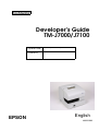
Developer’s Guide
TM-J7000/J7100
Copied Date
,
,
Copied by
EPSON
English
403221801
Confidential
TM-J7000/J7100 Developer’s Guide
Confidential
CONFIDENTIALITY AGREEMENT
BY USING THIS DOCUMENT, YOU AGREE TO ABIDE BY THE TERMS OF THIS AGREEMENT. PLEASE RETURN
THIS DOCUMENT IMMEDIATELY IF YOU DO NOT AGREE TO THESE TERMS.
❏
This document contains confidential, proprietary information of Seiko Epson Corporation or its affiliates. You
must keep such information confidential. If the user is a business entity or organization, you must limit disclosure
to your employees, agents, and contractors who have a need to know and who are also bound by obligations of
confidentiality.
❏
On the earlier of (a) termination of your relationship with Seiko Epson, or (b) Seiko Epson’s request, you must
stop using the confidential information. You must then return or destroy the information, as directed by Seiko
Epson.
❏
If a court, arbitrator, government agency, or the like orders you to disclose any confidential information, you must
immediately notify Seiko Epson. You agree to give Seiko Epson reasonable cooperation and assistance in resisting
disclosure.
❏
You may use confidential information only for the purpose of operating or servicing the products to which the
document relates, unless you obtain the prior written consent of Seiko Epson for some other use.
❏
Seiko Epson warrants that it has the right to disclose the confidential information. SEIKO EPSON MAKES NO
OTHER WARRANTIES CONCERNING THE CONFIDENTIAL INFORMATION OR ANY OTHER
INFORMATION IN THE DOCUMENT, INCLUDING (WITHOUT LIMITATION) ANY WARRANTY OF TITLE
OR NON-INFRINGEMENT. Seiko Epson has no liability for loss or damage arising from or relating to your use of
or reliance on the information in the document.
❏
You may not reproduce, store, or transmit the confidential information in any form or by any means (electronic,
mechanical, photocopying, recording, or otherwise) without the prior written permission of Seiko Epson.
❏
Your obligations under this Agreement are in addition to any other legal obligations. Seiko Epson does not waive
any right under this Agreement by failing to exercise it. The laws of Japan apply to this Agreement.
❏
This document shall apply only to the product(s) identified herein.
❏
No part of this document may be reproduced, stored in a retrieval system, or transmitted in any form or by any
means, electronic, mechanical, photocopying, recording, or otherwise, without the prior written permission of
Seiko Epson Corporation.
❏
The contents of this document are subject to change without notice. Please contact us for the latest information.
❏
While every precaution has been taken in the preparation of this document, Seiko Epson Corporation assumes no
responsibility for errors or omissions.
❏
Neither is any liability assumed for damages resulting from the use of the information contained herein.
❏
Neither Seiko Epson Corporation nor its affiliates shall be liable to the purchaser of this product or third parties
for damages, losses, costs, or expenses incurred by the purchaser or third parties as a result of: accident, misuse, or
abuse of this product or unauthorized modifications, repairs, or alterations to this product, or (excluding the U.S.)
failure to strictly comply with Seiko Epson Corporation's operating and maintenance instructions.
❏
Seiko Epson Corporation shall not be liable against any damages or problems arising from the use of any options
or any consumable products other than those designated as Original EPSON Products or EPSON Approved
Products by Seiko Epson Corporation.
CAUTIONS
TRADEMARKS
EPSON® and ESC/POS® are registered trademarks of Seiko Epson Corporation.
General Notice: Other product and company names used herein are for identification
Rev. A
i
Confidential
purposes only and may be trademarks of their respective companies.
General Notice: Other product and company names used herein are for identification purposes only and may be
trademarks of their respective companies.
ESC/POS Proprietary Command System
EPSON took the initiative by introducing ESC/POS, a proprietary POS printer command system including patented
commands and enabling versatile POS system construction with high scalability. Compatible with all types of EPSON
POS printers and displays, this proprietary control system also offers the flexibility to easily make future upgrades. Its
popularity is worldwide.
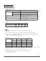
Revision Information
Revision
Page
Altered Items and Contents
Rev. A
all page
newly authorized
About This Booklet
This booklet was created to provide the information only on the features specific to the TMJ7000/J7100 printer for anyone who needs the information before the mass production.
Key to Symbols
The symbols in this booklet are identified by their level of importance, as defined below. Read
the following carefully before handling the product.
WARNING:
You must follow warnings carefully to avoid serious bodily injury.
CAUTION:
Provides information that must be observed to prevent damage to the equipment or
loss of data.
❏ Possibility of sustaining physical injuries.
❏ Possibility of causing physical damages.
❏ Possibility of causing information loss.
Note:
Provides important information and useful tips on handling the equipment.
ii
Rev. A
Confidential
TM-J7000/J7100 Developer’s Guide
Safety Precautions
This section presents important information to ensure safe and effective use of this product.
Please read this section carefully and store it in an accessible location.
WARNING:
❏ Shut down your equipment immediately if it produces smoke, a strange odor, or
unusual noise. Continued use may lead to fire or electric shock. Immediately unplug
the equipment and contact your dealer or a Seiko Epson service center for advice.
❏ Never attempt to repair this product yourself. Improper repair work can be
dangerous.
❏ Never disassemble or modify this product. Tampering with this product may result in
injury, fire, or electric shock.
❏ Be sure to use the specified power source. Connection to an improper power source
may cause fire or shock.
❏ Never insert or disconnect the power plug with wet hands. Doing so may result in
severe shock.
❏ Do not allow foreign matter to fall into the equipment. Penetration by foreign
objects may lead to fire or shock.
❏ If water or other liquid spills into this equipment, do not continue to use it. Continued
use may lead to fire or shock. Unplug the power cord immediately and contact your
dealer or a Seiko Epson service center for advice.
❏ Do not place multiple loads on the power outlet (wall outlet). Overloading the outlet
may lead to fire.
❏ Always supply power directly from a standard domestic power outlet.
❏ Handle the power cord with care. Improper handling may lead to fire or shock.
•
Do not modify or attempt to repair the cord.
•
Do not place any object on top of the cord.
•
Avoid excessive bending, twisting, and pulling.
•
Do not place cord near heating equipment.
•
Check that the plug is clean before plugging it in.
•
Be sure to push the prongs all the way in.
❏ If the cord becomes damaged, obtain a replacement from your dealer or a Seiko
Epson service center.
Rev. A
iii
Confidential
CAUTION:
❏ Do not connect cables in ways other than those mentioned in this manual.
Different connections may cause equipment damage and burning.
❏ Be sure to set this equipment on a firm, stable, horizontal surface.
Product may break or cause injury if it falls.
❏ Do not use in locations subject to high humidity or dust levels.
Excessive humidity and dust may cause equipment damage, fire, or shock.
❏ Do not place heavy objects on top of this product. Never stand or lean on this
product. Equipment may fall or collapse, causing breakage and possible injury.
❏ To ensure safety, unplug this product before leaving it unused for an extended
period.
❏ Before moving the product, unplug it and unplug all cables connected to it.
❏ If ink leaks out of the printer, wipe up the ink with a cloth or similar material
immediately and contact your dealer or a Seiko Epson service center for advice.
Safety Label
WARNING:
Do not connect a telephone line to the drawer kick out connector or to the display
module connector; otherwise, the printer and the telephone line may be damaged.
iv
Rev. A
Confidential
TM-J7000/TM-J7100 Developer’s Guide
Developer’s Guide
TM-J7000/J7100
Revision Information . . . . . . . . . . . . . . . . . . . . . . . . . . . . . . . . . . . . . . . . . . . . . . . . . .
About This Booklet . . . . . . . . . . . . . . . . . . . . . . . . . . . . . . . . . . . . . . . . . . . . . . . . . . . .
Key to Symbols . . . . . . . . . . . . . . . . . . . . . . . . . . . . . . . . . . . . . . . . . . . . . . . . . . . . . . .
Safety Precautions . . . . . . . . . . . . . . . . . . . . . . . . . . . . . . . . . . . . . . . . . . . . . . . . . . . . .
Safety Label . . . . . . . . . . . . . . . . . . . . . . . . . . . . . . . . . . . . . . . . . . . . . . . . . . . . . . . . . . .
ii
ii
ii
iii
iv
Chapter 1 Product Overview
Product Structure . . . . . . . . . . . . . . . . . . . . . . . . . . . . . . . . . . . . . . . . . . . . . . . . . . . . . .
Part Names . . . . . . . . . . . . . . . . . . . . . . . . . . . . . . . . . . . . . . . . . . . . . . . . . . . . . . .
Models . . . . . . . . . . . . . . . . . . . . . . . . . . . . . . . . . . . . . . . . . . . . . . . . . . . . . . . . . . .
Accessories . . . . . . . . . . . . . . . . . . . . . . . . . . . . . . . . . . . . . . . . . . . . . . . . . . . . . . .
Options . . . . . . . . . . . . . . . . . . . . . . . . . . . . . . . . . . . . . . . . . . . . . . . . . . . . . . . . . .
Consumables . . . . . . . . . . . . . . . . . . . . . . . . . . . . . . . . . . . . . . . . . . . . . . . . . . . . .
Printer Specifications . . . . . . . . . . . . . . . . . . . . . . . . . . . . . . . . . . . . . . . . . . . . . . . . . . .
Printing . . . . . . . . . . . . . . . . . . . . . . . . . . . . . . . . . . . . . . . . . . . . . . . . . . . . . . . . . .
Print method . . . . . . . . . . . . . . . . . . . . . . . . . . . . . . . . . . . . . . . . . . . . . . . . . .
Interfaces . . . . . . . . . . . . . . . . . . . . . . . . . . . . . . . . . . . . . . . . . . . . . . . . . . . . . . . . .
Reliability . . . . . . . . . . . . . . . . . . . . . . . . . . . . . . . . . . . . . . . . . . . . . . . . . . . . . . . .
Buffer Sizes . . . . . . . . . . . . . . . . . . . . . . . . . . . . . . . . . . . . . . . . . . . . . . . . . . . . . . .
Environmental Conditions . . . . . . . . . . . . . . . . . . . . . . . . . . . . . . . . . . . . . . . . . .
Electrical Characteristics . . . . . . . . . . . . . . . . . . . . . . . . . . . . . . . . . . . . . . . . . . . .
Overall Dimensions . . . . . . . . . . . . . . . . . . . . . . . . . . . . . . . . . . . . . . . . . . . . . . . .
Product Handling . . . . . . . . . . . . . . . . . . . . . . . . . . . . . . . . . . . . . . . . . . . . . . . . . . . . .
Control Panel (LEDs and Buttons) . . . . . . . . . . . . . . . . . . . . . . . . . . . . . . . . . . .
LEDs . . . . . . . . . . . . . . . . . . . . . . . . . . . . . . . . . . . . . . . . . . . . . . . . . . . . . . . .
Buttons . . . . . . . . . . . . . . . . . . . . . . . . . . . . . . . . . . . . . . . . . . . . . . . . . . . . . .
Power Switch and Power Switch Cover . . . . . . . . . . . . . . . . . . . . . . . . . . . . . . . . . . .
Executing the power-off sequence . . . . . . . . . . . . . . . . . . . . . . . . . . . . . . . . . . .
Power Switch Cover . . . . . . . . . . . . . . . . . . . . . . . . . . . . . . . . . . . . . . . . . . . . . . .
Installing or Replacing Roll Paper . . . . . . . . . . . . . . . . . . . . . . . . . . . . . . . . . . . . . . .
Inserting Slip Paper . . . . . . . . . . . . . . . . . . . . . . . . . . . . . . . . . . . . . . . . . . . . . . . . . . . .
Installing or Replacing an Ink Cartridge . . . . . . . . . . . . . . . . . . . . . . . . . . . . . . . . . .
Instructions . . . . . . . . . . . . . . . . . . . . . . . . . . . . . . . . . . . . . . . . . . . . . . . . . . . . . . .
Disposal of Used Cartridges . . . . . . . . . . . . . . . . . . . . . . . . . . . . . . . . . . . . . . . .
Ink Cartridge Life . . . . . . . . . . . . . . . . . . . . . . . . . . . . . . . . . . . . . . . . . . . . . . . . .
MICR Printing (Factory installed option) . . . . . . . . . . . . . . . . . . . . . . . . . . . . . . . . .
Cleaning the MICR Mechanism . . . . . . . . . . . . . . . . . . . . . . . . . . . . . . . . . . . . .
Notes on using the MICR reader . . . . . . . . . . . . . . . . . . . . . . . . . . . . . . . . .
Self test . . . . . . . . . . . . . . . . . . . . . . . . . . . . . . . . . . . . . . . . . . . . . . . . . . . . . . . . . . . . . .
Self-test on roll paper . . . . . . . . . . . . . . . . . . . . . . . . . . . . . . . . . . . . . . . . . . . . . .
Self-test on a cut sheet . . . . . . . . . . . . . . . . . . . . . . . . . . . . . . . . . . . . . . . . . . . . . .
Self-test of the endorsement mechanism . . . . . . . . . . . . . . . . . . . . . . . . . . . . . .
Hexadecimal Dumping . . . . . . . . . . . . . . . . . . . . . . . . . . . . . . . . . . . . . . . . . . . . . . . . .
Shipping Procedure . . . . . . . . . . . . . . . . . . . . . . . . . . . . . . . . . . . . . . . . . . . . . . . . . . . .
Troubleshooting . . . . . . . . . . . . . . . . . . . . . . . . . . . . . . . . . . . . . . . . . . . . . . . . . . . . . . .
Cleaning . . . . . . . . . . . . . . . . . . . . . . . . . . . . . . . . . . . . . . . . . . . . . . . . . . . . . . . . .
Error LED Codes . . . . . . . . . . . . . . . . . . . . . . . . . . . . . . . . . . . . . . . . . . . . . . . . . .
Errors that Automatically Recover . . . . . . . . . . . . . . . . . . . . . . . . . . . . . . .
Errors that are Possible to Recover . . . . . . . . . . . . . . . . . . . . . . . . . . . . . . .
Errors that are Impossible to Recover . . . . . . . . . . . . . . . . . . . . . . . . . . . . . . . . .
Printer Operation When an Error Occurs . . . . . . . . . . . . . . . . . . . . . . . . . . . . .
Data Receive Error . . . . . . . . . . . . . . . . . . . . . . . . . . . . . . . . . . . . . . . . . . . . . . . . .
Rev. A
1
1
2
2
2
2
3
3
3
3
3
3
4
4
4
5
5
6
7
8
8
9
9
11
11
12
15
15
15
16
16
16
17
17
18
18
19
20
20
21
21
22
23
23
24
1
Confidential
Chapter 2 Adjustments and Settings
Using Different Paper Width . . . . . . . . . . . . . . . . . . . . . . . . . . . . . . . . . . . . . . . . . . . . 1
Paper Near-End Sensor . . . . . . . . . . . . . . . . . . . . . . . . . . . . . . . . . . . . . . . . . . . . . . . . . 1
DIP Switches . . . . . . . . . . . . . . . . . . . . . . . . . . . . . . . . . . . . . . . . . . . . . . . . . . . . . . . . . . 3
Memory Switches . . . . . . . . . . . . . . . . . . . . . . . . . . . . . . . . . . . . . . . . . . . . . . . . . . . . . . 4
Memory switch setting mode . . . . . . . . . . . . . . . . . . . . . . . . . . . . . . . . . . . . . . . . 7
Starting the memory switch setting mode . . . . . . . . . . . . . . . . . . . . . . . . . 8
Ending memory switch setting mode . . . . . . . . . . . . . . . . . . . . . . . . . . . . . 8
Operating procedure . . . . . . . . . . . . . . . . . . . . . . . . . . . . . . . . . . . . . . . . . . . 9
Connection Form and Cables . . . . . . . . . . . . . . . . . . . . . . . . . . . . . . . . . . . . . . . . . . . . 12
Serial Connection . . . . . . . . . . . . . . . . . . . . . . . . . . . . . . . . . . . . . . . . . . . . 12
Parallel Connection . . . . . . . . . . . . . . . . . . . . . . . . . . . . . . . . . . . . . . . . . . 15
USB . . . . . . . . . . . . . . . . . . . . . . . . . . . . . . . . . . . . . . . . . . . . . . . . . . . . . . . . 15
Ethernet . . . . . . . . . . . . . . . . . . . . . . . . . . . . . . . . . . . . . . . . . . . . . . . . . . . . 16
For IBM POS systems . . . . . . . . . . . . . . . . . . . . . . . . . . . . . . . . . . . . . . . . . . . . . . . . . . . 17
Chapter 3 Application Development Information
Key words in Q & A . . . . . . . . . . . . . . . . . . . . . . . . . . . . . . . . . . . . . . . . . . . . . . . . . . . . 2
Miscellaneous Information in a Q & A Format . . . . . . . . . . . . . . . . . . . . . . . . . . . . . 4
Single-Pass Processing . . . . . . . . . . . . . . . . . . . . . . . . . . . . . . . . . . . . . . . . . . . . . . . . . . 5
Chapter 4 Specifications
Product Specifications . . . . . . . . . . . . . . . . . . . . . . . . . . . . . . . . . . . . . . . . . . . . . . . . 1
Print Specifications . . . . . . . . . . . . . . . . . . . . . . . . . . . . . . . . . . . . . . . . . . . . . . . . 2
Character Specifications . . . . . . . . . . . . . . . . . . . . . . . . . . . . . . . . . . . . . . . . . . . . 4
Receipt Printer Section . . . . . . . . . . . . . . . . . . . . . . . . . . . . . . . . . . . . . . . . . . . . . . 5
Characters per Line and Printable Area for Roll paper . . . . . . . . . . . . . . 5
Paper Feed Specifications . . . . . . . . . . . . . . . . . . . . . . . . . . . . . . . . . . . . . . . 5
Printable Area . . . . . . . . . . . . . . . . . . . . . . . . . . . . . . . . . . . . . . . . . . . . . . . . . 6
Printing Position Versus Cutter Position . . . . . . . . . . . . . . . . . . . . . . . . . . . . . . 7
Slip Printer Section . . . . . . . . . . . . . . . . . . . . . . . . . . . . . . . . . . . . . . . . . . . . . . . . . 7
Characters per Line and Printable Area for Slips . . . . . . . . . . . . . . . . . . . 7
Paper Feed Specifications . . . . . . . . . . . . . . . . . . . . . . . . . . . . . . . . . . . . . . . 8
Printable Area . . . . . . . . . . . . . . . . . . . . . . . . . . . . . . . . . . . . . . . . . . . . . . . . . 8
MICR Reader Section (Factory-Installed Option) . . . . . . . . . . . . . . . . . . . . . . . 9
Reading Method . . . . . . . . . . . . . . . . . . . . . . . . . . . . . . . . . . . . . . . . . . . . . . . 9
Recognition Rate . . . . . . . . . . . . . . . . . . . . . . . . . . . . . . . . . . . . . . . . . . . . . . . 9
Insertion Direction and Endorsement Printing . . . . . . . . . . . . . . . . . . . . . 10
Notes on Using the MICR Reader . . . . . . . . . . . . . . . . . . . . . . . . . . . . . . . . 10
Endorsement Mechanism Section (Factory-Installed Option) . . . . . . . . . . . . . 11
Characters per Line and Printable Area for Endorsement . . . . . . . . . . . 11
Printable Area . . . . . . . . . . . . . . . . . . . . . . . . . . . . . . . . . . . . . . . . . . . . . . . . . 11
Notes on Using the Endorsement Mechanism . . . . . . . . . . . . . . . . . . . . . . 12
Paper Specification . . . . . . . . . . . . . . . . . . . . . . . . . . . . . . . . . . . . . . . . . . . . . . . . . . . . . 13
Paper Roll Specification . . . . . . . . . . . . . . . . . . . . . . . . . . . . . . . . . . . . . . . . . . . . . 13
Slip Paper Specification . . . . . . . . . . . . . . . . . . . . . . . . . . . . . . . . . . . . . . . . . . . . . 13
Notes on slip paper . . . . . . . . . . . . . . . . . . . . . . . . . . . . . . . . . . . . . . . . . . . . 13
Endorsement Paper Specification . . . . . . . . . . . . . . . . . . . . . . . . . . . . . . . . . . . . 14
2
Rev. A
Confidential
TM-J7000/TM-J7100 Developer’s Guide
Chapter 1
Product Overview
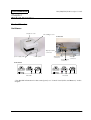
Product Structure
Part Names
roll paper cover
ink cartridge cover
Connectors
display module
connector
power supply switch
control panel
drawer kick out
connector
power supply
connector
interface
connector
Control Panel
TM-J7000
TM-J7100
* For detailed information for the control panel, see “Control Panel (LEDs and Buttons)” in this
chapter.
Rev. A
Product Overview 1-1
Confidential
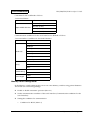
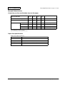
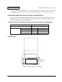
Models
Product name
Ink system
Supplied ink cartridge
TM-J7000 series
Monochrome
SJIC8 (K): (black)
TM-J7100 series
2-color
One of the following
SJIC6 (K) + SJIC7 (R): (black) + (red)
SJIC6 (K) + SJIC7 (G):(black) + (green)
SJIC6 (K) + SJIC7 (B): (black) + (blue)
Accessories
❏ Paper roll (60 mm in diameter)
❏ Ink cartridge
[TM-J7000] SJIC8 ✕ 1
[TM-J7100] SJIC6 ✕ 1, SJIC7 ✕ 1
❏ User's manual
❏ Hexagonal millimeter screws (only for the serial interface printer) (2)
❏ Power switch cover
❏ Instruction sheets
Options
❏ Power supply: EPSON PS-180
❏ Universal interface boards (except for UB-P02)
Interface
Product name
Serial
UB-S01 (RS-232)
UB-S02 (RS-485)
Parallel
UB-P02II
USB
UB-U01 / U01II (Downstream hub provided)
UB-U02 / U02II (Downstream hub not provided)
Ethernet
UB-E01
Consumables
❏ Ink cartridge
[TM-J7000] SJIC8
[TM-J7100] SJIC6, SJIC7
Note:
Use Seiko Epson specified ink cartridges. Performance of the printer when other ink cartridges are used is
not guaranteed.
1-2 Product Overview
Rev. A
Confidential
TM-J7000/TM-J7100 Developer’s Guide
Printer Specifications
Printing
Print method
Serial inkjet dot matrix
❏ TM-J7000: single-color, 64 nozzles × 1 line
❏ TM-J7100: two-color, 64 nozzles × 2 lines
❏ Density: 180 × 180 dpi
Interfaces
❏ Standard: RS-232 and IEEE 1284 parallel
❏ Options: RS-485, all UB boards, except the UB-P02, 10Base-T
Reliability
❏ Life
•
Mechanism: Receipt: 15,000,000 lines, Slip: 5,000,000 lines
•
Print head: 1600 million shots/nozzle (Shots are defined as the numbers of pulses
energized for the print head.)
•
Autocutter: 1,500,000 cuts (End of life: the printer is defined to have reached the end of
its life when it reaches the beginning of the Wearout Period.)
•
MICR reader mechanism (factory-installed option): 240,000 passes (when used with US
personal checks)
•
Endorsement mechanism: 240,000 passes (when used with US personal checks)
❏ MTBF: 180,000 hours (Failure is defined as a random failure occurring during the random
failure period.)
❏ MCBF: 50,000,000 lines (This is an average failure interval based on failures relating to
wearout and random failures up to the life of 20,000,000 lines (receipt: 15,000,000 lines plus
slip: 5,000,000 lines)
Buffer Sizes
❏ Receive: 4KB
❏ User-defined (both for user-defined characters and downloaded bit images): 12KB
❏ NV graphics and user NV memory: 384KB
Rev. A
Product Overview 1-3
Confidential
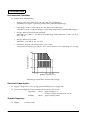
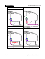
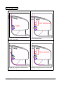
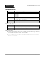
Environmental Conditions
❏ Temperature and Humidity:
•
Printing: 10 to 35°C {50 to 95°F}, 20 - 80% RH (non-condensing)
(Shaded area in figure “Operating Temperature and Humidity Range.”)
•
Operating: 5 to 40°C {41 to 104°F}, 20 - 80% RH (non-condensing)
(Area drawn with a solid line in figure “Operating Temperature and Humidity Range.”)
•
Storage: When packed (ink not installed)
-20 to 60C {-4 to 140F}, 5 - 85% RH (non-condensing) (within 120 hours at -20°C {68°F} or
60°C {140°F}
•
Storage: When ink is loaded
-20 to 40°C {-4 to 104°F}, 20 - 85% RH
•
Maximum absolute rated temperature: 70°C {158F}
(The printer must be kept at or below 70°C {158°F} whenever it is operating or in storage.
Relative humidity (RH%)
80
55
20
5
10
27
35 40
Ambient temperature (°C)
Operating Temperature and Humidity Range
Electrical Characteristics
❏ Supply voltage 24 V ± 2.4 V (using optional EPSON power supply 180)
❏ Current consumption (except when the drawer kick-out is used):
Operating
Mean: Approximately 1A
(all lines contain character font A α-N)
Standby
Mean: Approximately 50mA
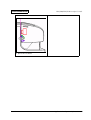
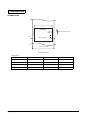
Overall Dimensions
❏ Height:
1-4 Product Overview
188 mm {7.40"}
Rev. A
Confidential
TM-J7000/TM-J7100 Developer’s Guide
195 mm {7.68"}
❏ Depth:
237 mm {9.33"}
❏ Mass:
Approximately 4.4 kg
237
❏ Width:
188
195
Product Handling
Control Panel (LEDs and Buttons)
PAPER FEED
PAPER FEED
CLEANING
TM-J7100
TM-J7000
POWER
ERROR
PAPER OUT
CUT SHEET
INK OUT (black)
Rev. A
CLEANING
POWER
ERROR
PAPER OUT
INK OUT (color)
CUT SHEET
INK OUT (black)
Product Overview 1-5
Confidential
LEDs
POWER
Lights when the power is on and is off when the power is off; flashes during cleaning and other
operations such as power-on and power-off.
Power on process (when an operation is being executed): Flashing
320 ms
320 ms
Power off process (after DLE DC4, fn = 2 is executed): Flashing
160 ms
2400 ms
Note:
Never open the printer cover or turn off the printer when the POWER LED is flashing.
ERROR
Lights when the printer is offline except during paper feeding using the PAPER FEED button,
during self-test, or cleaning. Off when the printer is online. Flashes when an error occurs. See the
Error LED Codes section in this Chapter.
INK OUT
Lights when the ink cartridge is not installed or ink is out. The ink cartridge needs to be
replaced. Off when the ink cartridge is installed and ink is adequate. Flashes when the ink is
nearly out. (If the ink is out, the printer also goes offline and the ERROR LED lights.) The
TM-J7000 has two INK OUT LEDs, one for the color cartridge and one for the black cartridge.)
Note:
The number of printable characters from when the ink near end status is detected to when the ink is out
differs depending on the conditions. When ink near end is detected, prepare to replace the ink cartridge.
Detection of ink cartridge installation and the ink near end status is performed only when the carriage
cover is closed. If the carriage cover is open, the INK OUT LED keeps the same status as before the carriage
cover was opened.
1-6 Product Overview
Rev. A
Confidential
TM-J7000/TM-J7100 Developer’s Guide
PAPER OUT
Lights when roll paper is out or nearly out. Flashes when the printer is in the self test standby
state.
CUT SHEET
Lights when cut sheet (slip, check) is selected as print sheet. Off when roll paper is selected as
print sheet. Flashes when the printer is in the cut sheet insertion or removal waiting state.
Slip insertion waiting
approx. 320
Personal check insertion waiting
approx. 1760
approx. 320
Slip removal waiting state
approx. 2080
approx. 320
Buttons
PAPER FEED
PAPER FEED feeds the roll paper based on the line spacing set by the ESC 2 or ESC 3 command.
The printer feeds the roll paper if the roll paper is selected as the paper source or feeds the cut
sheet when the cut sheet is selected as the paper source.
The back of a slip is fed by the PAPER FEED button in the reverse direction to when the paper is
fed in the forward direction.
Note:
Paper cannot be fed using this button in the following cases:
Rev. A
•
When check is selected as the print sheet.
•
Roll paper cover is open when roll paper is selected as print sheet.
•
Printer is in the slip insertion or removal state when slip is selected as print sheet.
Product Overview 1-7
Confidential
•
When cleaning is being performed or an error has occurred with any sheet selected.
•
When it is disabled with the ESC c 5 command.
There is the case that even if the paper source is changed, the printer may feed the previously
selected paper source.
A slip will be fed in the following case; if roll paper is selected as the paper source with the slip
paper clamped and the PAPER FEED button is pressed before the printer receives data from the
host.
CLEANING
If printing becomes faint or uneven and the INK OUT LED is not on or flashing, use this button to
clean the print head. Press the button until the printer mechanism begins to clean the print head
(more than 3 seconds). When the cleaning stops, the printer is ready for normal printing.
Note:
Do not use the CLEANING button unless there is a problem with print quality. Unnecessary cleaning
will waste ink.
Power Switch and Power Switch Cover
The power switch is on the front of the printer. Press the power switch to turn on the printer.
Note:
Turn on the power only after connecting the power supply.
Executing the power-off sequence
It is recommended to turn the power off only after executing the power-off command (DLE DC4
fn = 2). If the power is turned off without executing the power-off command, the ink will be
wasted since the cleaning is done when the printer is turned on the next time, or the ink nozzle
will be clogged if the unused period exceeds two weeks.
Note:
Never open the printer cover or turn off the printer when the POWER LED is flashing.
1-8 Product Overview
Rev. A
Confidential
TM-J7000/TM-J7100 Developer’s Guide
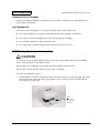
Power Switch Cover
You can use the enclosed power switch cover to make sure that the power switch is not accidentally
pressed. Just press the cover into place to install it. If you need to turn the power switch on or off
with the cover attached, you can insert a thin tool into one of the holes in the cover to operate the
switch.
WARNING:
If an accident occurs when the power switch cover is attached, immediately unplug
the power supply cable to avoid fire.
If you are going to store the printer or leave it unused for a long time, turn it off using the power
switch on the printer.
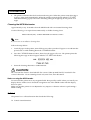
Installing or Replacing Roll Paper
CAUTION:
Be careful not to insert your fingers into the paper exit. The cutter blade is installed inside
the paper exit and you might be injured.
Rev. A
Product Overview 1-9
Confidential
CAUTION:
Be sure to use roll paper that meets the specifications.
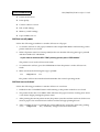
Follow these steps to install or replace paper:
1. Make sure the printer is on.
2. Open the roll paper cover by pressing the cover open button.
3. Remove the used roll paper core if there is one.
4. Put the roll paper inside the printer in the correct direction, as shown in the illustrations
below.
5. Pull out the leading edge of the roll paper; then close the roll paper cover until it is firmly
locked by pushing the top of the cover.
6. The printer will automatically feed the roll paper to remove any slack in the paper.
Note:
Do not open the roll paper cover during printing or paper feeding.
1-10 Product Overview
Rev. A
Confidential
TM-J7000/TM-J7100 Developer’s Guide
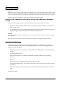
Inserting Slip Paper
Note:
Be sure the paper is flat, without curls, folds, or wrinkles.
Do not insert any multiple sheet paper because this may cause a paper jam. Use only single sheet paper.
Because the printer is an inkjet printer, pressure sensitive copy paper cannot be used.
To prevent jams, roll paper must be installed even for printing on slip paper.
Be sure to insert a slip with the right side of the paper against the right side of the paper guide as far as it
will go, as shown in the illustration. See the label instructions attached to the printer as a guide.
Installing or Replacing an Ink Cartridge
CAUTION:
Usage:
Do not disassemble the cartridge. The ink can permanently stain clothing.
Do not refill ink cartridges. Spills can result, causing damage to the printer.
Do not remove the cartridge except to replace it or to prepare the printer for shipment.
Otherwise, ink may be wasted and the life of the ink cartridge may be reduced.
For good printing quality, do not remove the ink cartridge from its packing until
immediately before installing it.
Use up the ink cartridge within 6 months after unpacking it.
The expiration date is indicated on the cartridge box or the ink cartridge itself.
Print quality problems may occur if an ink cartridge that is almost empty (the INK OUT
LED flashes) is removed and reinstalled.
Rev. A
Product Overview 1-11
Confidential
A used cartridge may have some ink on the convex part of the bottom of the cartridge.
Avoid touching that part to keep your hands clean.
Do not puncture the convex part of the bottom of the ink cartridge or remove the
transparent film on the bottom of the ink cartridge; otherwise the ink might leak.
Once the ink cartridge is used, the ink supply needle (plastic projection) in the ink
cartridge holder that supplies ink to the printer is covered with ink. Avoid touching the
cartridge holder to keep your hands clean.
Use Seiko Epson specified ink cartridges. Performance of the printer when other ink
cartridges are used is not guaranteed.
Do not open or close the ink cartridge cover during printing. Misalignment of the print
position will occur.
Storage:
Keep the ink cartridge out of the reach of children. Do not drink the ink.
Do not store the ink cartridge where it will be subject to high temperatures or freezing.
Instructions
When the INK OUT LED flashes, it is almost time to change the ink cartridge. Change the
cartridge as soon as it is convenient. When the INK OUT LED is on, printing stops and you must
change the cartridge.
The TM-J7100 has two separate cartridges, one each for black and colored ink (either red, green,
or blue). Therefore, the TM-J7100 has two INK OUT LEDs, one for the black and one for the color.
Follow these steps to install an ink cartridge for the first time or to replace an empty ink
cartridge.
1. Make sure the printer is on. If it is not on, plug in the power supply cable and turn on the
power using the switch on the front of the printer.
2. Make sure an INK OUT LED is on or flashing. When using two colors, notice which ink
cartridge INK OUT LED is on or flashing; this indicates which cartridge is empty.
3. Be sure that roll paper is installed.
1-12 Product Overview
Rev. A
Confidential
TM-J7000/TM-J7100 Developer’s Guide
4. Open the ink cartridge cover using the tabs on the sides of the cover.
5. Lift up the empty ink cartridge by using the tab.
TM-J7000
TM-J7100
CAUTION:
Do not put your fingers inside the ink cartridge compartment or you may be injured
by a plastic projection.
Once the ink cartridge is used, the ink supply needle (plastic projection) in the ink
cartridge holder that supplies ink to the printer is covered with ink. Avoid touching
the cartridge holder to keep your hands clean.
Rev. A
Product Overview 1-13
Confidential
6. Take a new ink cartridge out of its packing and remove the yellow tape.
CAUTION:
You must not remove any tape on which the EPSON logo is printed.
7. Carefully insert a new ink cartridge from the top and push it firmly but gently until it clicks
into place. Be sure the inserting direction is correct, as shown in the illustrations below.
TM-J7000
TM-J7100
8. Close the ink cartridge cover completely.
Note:
The INK OUT LED will now be off.
The POWER LED flashes for approximately 1 minute as the ink delivery system is charged. To
save ink, this sequence will not be executed every time you replace an ink cartridge. The time to
execute the sequence is controlled by the printer.
Note:
Do not turn off the power while the POWER LED is flashing. This will waste ink because the printer has
to re-start the ink charging process. Be sure not to open the printer cover while the POWER LED is
flashing.
When the POWER LED quits flashing and stays on, the printer is ready for printing.
1-14 Product Overview
Rev. A
Confidential
TM-J7000/TM-J7100 Developer’s Guide
Disposal of Used Cartridges
Dispose of used ink cartridges as industrial waste products. Obey the laws and regulations of
your country and district.
Ink Cartridge Life
To make your ink cartridges last as long as possible, follow these simple rules:
❏ Don’t turn off the power supply switch immediately after printing is completed.
❏ Don’t remove an ink cartridge unless you are replacing the cartridge.
❏ Don’t turn the printer on and off unnecessarily.
❏ Don’t press the CLEANING button unless the print is faint or uneven.
MICR Printing (Factory installed option)
CAUTION:
Do not insert checks with staples in them. This may cause paper jams, MICR reading
errors, and damage to the MICR head.
Never open the roll paper cover while the MICR reader is being used.
Be sure the checks are flat, without curls, folds, or wrinkles.
Do not use multipart checks.
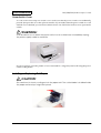
1. Wait until the CUT SHEET LED blinks. Then insert the check face up with the right side of the
check against the right side of the paper guide as far as it will go. Be sure that the MICR
characters are on the right.
MICR
characters
on this side
face up
Rev. A
Product Overview 1-15
Confidential
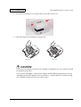
2. The printer will detect the check and start drawing it in. When the printer starts drawing it
in, let go of the check immediately. When the printer ejects the check and the CUT SHEET
LED starts blinking again; remove the check by pulling it straight up; do not pull it at an
angle.
Cleaning the MICR Mechanism
Approximately every 12 months clean the MICR head with a moistened cleaning sheet.
Use the following or an equivalent commercially available cleaning sheet:
PRESAT brand (KIC) “CHECK READER CLEANING CARD.”
Note:
Be sure not to use an adhesive cleaning sheet.
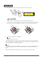
Follow the steps below:
1. Load roll paper in the printer; turn off the power; then open the roll paper cover and turn the
power back on while holding down the CLEANING button.
2. Press the CLEANING button 7 times; then close the paper roll cover. The printer prints the
following message on the roll paper and the CUT SHEET LED flashes.
3. Insert the cleaning sheet like a standard check.
CAUTION:
Be sure that the sheet is inserted with the correct side up and that it is inserted in the
correct direction. Use a cleaning sheet only one time; then discard it.
Notes on using the MICR reader
Do not install the printer near any magnetic fields. Be especially careful where you install your
display device and be sure to check the recognition rate of the MICR reader with the display
device in place.
Make sure that the printer is not subjected to any impact or vibration when it is performing a
MICR reading.
Self test
The printer has a self-test function that checks the following:
❏ Control circuit functions
1-16 Product Overview
Rev. A
Confidential
TM-J7000/TM-J7100 Developer’s Guide
❏ Printer mechanisms
❏ Print quality
❏ Control software version
❏ DIP switch settings
❏ Memory switch settings
❏ Paper width to be set
Self-test on roll paper
Follow the following procedure to start the self-test on roll paper.
1. To start the self-test on roll paper, hold down the receipt FEED button while turning on the
printer with the cover closed.
2. When all printer states have been printed, make sure that the following message is printed
and the PAPER OUT LED blinks.
“If you want to continue SELF-TEST printing, please press FEED button.”
The printer is now in the self-test wait mode.
3. To continue the self-test, press the FEED button when the printer is in the self-test wait
mode.
4. Make sure that the following message is printed.
***
completed
***
The printer will now be initialized and returned to the normal operating mode.
Self-test on a cut sheet
Follow the following procedure to start the self-test on a cut sheet.
1. Hold down the CLEANING button while turning on the printer with the cover closed.
2. The printer flashes the CUT SHEET LED and enters the paper insertion waiting state. Insert
a cut sheet to begin printing the printer status.
3. After printing the current printer status, the printer ejects the cut sheet and waits for the next
sheet of paper to be inserted. Insert another cut sheet to begin printing the test.
4. After a number of lines are printed, the printer indicates the end of the self-test by printing
“***
completed
***,” initializes, and goes into the normal mode.
Rev. A
Product Overview 1-17
Confidential
NOTES:
Make sure to use a cut sheet with a width wider than 85 mm {3.35"} because the self-test on the cut sheet
is full-column printing regardless of the paper width that is currently selected. If the width of the cut sheet
is narrower than full-column print width, the ink may make the platen dirty beyond the edge of the paper.
When the self-test is performed on the cut sheet, roll paper also must be loaded.
Self-test of the endorsement mechanism (only for the endorsement-equipped
model)
Follow the following procedure to start the self-test of the endorsement mechanism.
1. Hold down the CLEANING button while turning on the printer with the cover open and
then close the cover.
2. The printer flashes the CUT SHEET LED and enters the paper waiting state. Insert paper to
begin printing the test printing with the endorsement mechanism.
NOTES:
User paper with a width narrower than 101.6 mm {4"} for the endorsement self-test. Otherwise, the paper
may be jammed.
When the self-test is performed with the endorsement mechanism, roll paper also must be loaded.
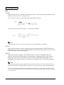
Hexadecimal Dumping
In hexadecimal dump mode, the data transmitted from the host computer is printed in
hexadecimal numbers and in their corresponding characters. Use the following procedure to
output a hexadecimal dump.
1. With the paper roll cover open, press and hold down the FEED button while turning on the
printer.
2. Close the paper roll cover.
Data received after this is printed in hexadecimal numbers and their corresponding
characters.
NOTES:
If no characters correspond to the data received, the printer prints "."
During hexadecimal dumping, any commands other than DLE EOT, DLE ENQ, and DLE DC4 do
not function.
3. When printing stops, turn off the power, or press the FEED button three times, or perform a
reset.
<Printing example>
1-18 Product Overview
Rev. A
Confidential
TM-J7000/TM-J7100 Developer’s Guide
Hexadecimal Dump
1B
21
00
1B
26
02
40
40
:
.
!
.
.
&
.
@
@
1B
25
01
1B
63
34
00
1B
:
.
%
.
.
c
4
.
.
41
42
43
44
45
46
47
48
:
A
B
C
D
E
F
G
H
Shipping Procedure
To ship the printer, follow these steps:
1. Remove the roll paper and ink cartridge.
2. Turn off the power supply.
3. Check that the POWER LED is off.
4. Remove the power supply connector and other connectors.
Keep the printer upright and horizontal while you pack it.
Rev. A
Product Overview 1-19
Confidential
Troubleshooting
Check the following cases. See also the “Error LED Codes” item to locate the causes.
✔ The print head temperature may be high or low. Wait until the print head cools or warms and
the printer resumes printing automatically.
✔ Make sure that the roll paper cover is properly closed.
✔ If a paper jam has occurred, open the roll paper cover or the ink cartridge cover and remove
the jammed paper. Do not pull the jammed paper by force or use tools. Be sure to remove it
manually.
✔ Turn off the power, wait several seconds, and then turn it on again.
Cleaning
If printing becomes faint or uneven and the INK OUT LED is not on or flashing, press the
CLEANING button until the printer mechanism begins to clean the print head (more than 3
seconds). The POWER LED flashes during cleaning. When the cleaning stops, the printer is
ready for normal printing.
Note:
Do not use the CLEANING button unless there is a problem with print quality. Unnecessary cleaning
will waste ink.
Do not turn off the power or open any covers while the POWER LED is flashing.
1-20 Product Overview
Rev. A
Confidential
TM-J7000/TM-J7100 Developer’s Guide
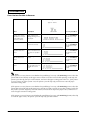
Error LED Codes
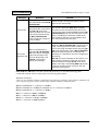
Errors that Automatically Recover
ERROR LED Flashing Pattern
approx. 320 ms
Error
Description
Recovery Condition
Roll paper cover
open error (when
auto recovery is
selected by the
memory switch)
Roll paper cover
open is detected
during printing on the
roll paper.
Recovers
automatically when
the cover is closed.
Print head high
temperature error (*)
The temperature of
the print head is too
high.
Recovers
automatically when
the print head cools.
Print head low
temperature error (*)
The temperature of
the print head is to
low.
Recovers
automatically when
the print head
temperature
increases.
(*) If the head temperature is only slightly out of range the printer can recover, but a large deviation from the
appropriate range causes an unrecoverable error as an internal circuit error.
Rev. A
Product Overview 1-21
Confidential
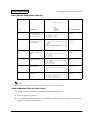
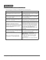
Errors that are Possible to Recover
ERROR LED Flashing Pattern
approx. 320 ms
Error
Description
Recovery Condition
Paper roll cover
open error (when
Possible recovery is
selected by the
memory switch)
Roll paper cover
open is detected
during printing on the
roll paper.
Recovers by DLE ENQ
(n = 1) or DLE ENQ (n
= 2) with the cover
closed.
Autocutter error
The autocutter does
not work correctly.
Recovers by DLE ENQ
(n = 1) or DLE ENQ (n
= 2) with the cover
closed.
Carriage home
position detection
error
The home position
cannot be detected
because of a paper
jam.
Recovers by DLE ENQ
(n = 1) or DLE ENQ (n
= 2) with the cover
closed.
Carriage out of
phase detection
error
The carriage is out of
phase.
Recovers by DLE ENQ
(n = 1) or DLE ENQ (n
= 2) with the cover
closed.
Cut sheet ejection
error
The cut sheet cannot
be ejected even if a
certain amount is
fed.
Recovers by DLE ENQ
(n = 1) or DLE ENQ (n
= 2) with the cover
closed.
Note:
If the printer recovers from an error that has the possibility of recovery with DLE ENQ (n = 1) when the
printer has selected the slip as the paper source and an error has occurred while printing on the slip, the
printer ejects the slip first if it is still remains, and enters the paper waiting state. However, if the printer
recovers from a cut sheet ejection error, the printer ejects the slip only, and does not enter the paper
insertion waiting state.
If the printer recovers from an error that has the possibility of recovery with DLE ENQ (n = 1) when the
printer has selected the slip as the paper source and an error has occurred except when printing on the slip,
the printer ejects the slip first if it is still remains, and selects the slip as the paper source, and does not
enter the paper insertion waiting state.
If the printer recovers from an error that has the possibility of recovery with DLE ENQ (n = 2) when slip
is set as the paper source, the printer ejects the slip only if it still remains.
1-22 Product Overview
Rev. A
Confidential
TM-J7000/TM-J7100 Developer’s Guide
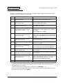
Errors that are Impossible to Recover
ERROR LED Flashing Pattern
approx. 320 ms
Error
Description
Recovery Condition
CPU execution
error
The CPU executes an
incorrect address or
the interface board is
not connected.
Impossible to
recover.
R/W error
After R/W checking,
the printer does not
work correctly.
Impossible to
recover.
approx. 5120 ms
High voltage error
The power supply
voltage is extremely
high.
Impossible to
recover.
Low voltage error
The power supply
voltage is extremely
low.
Impossible to
recover.
Drive circuit error
Drive circuit does not
work correctly.
Impossible to
recover.
UIB error
UIB does not work
correctly.
Impossible to
recover.
Note:
When any errors shown above occurs, turn off the power as soon as possible.
Printer Operation When an Error Occurs
The printer executes the following operations when detecting an error.
❏ Stops all printer operations.
❏ Goes to BUSY mode (if the printer is set to BUSY in offline state by memory switch 1-3. See
“Memory Switches” in Chapter 2.“
Rev. A
Product Overview 1-23
Confidential
❏ The ERROR LED flashes.
Data Receive Error
If one of the following errors occurs during serial interface communication, the printer prints “?”
or ignores the data, depending on the setting memory switch 1-4.
❏ Parity error
❏ Framing error.
❏ Overrun error
1-24 Product Overview
Rev. A
Confidential
TM-J7000/TM-J7100 Developer’s Guide
Chapter 2
Adjustments and Settings
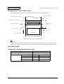
Using Different Paper Width
This printer accommodates 76 mm wide paper rolls with no adjustment; however you can
change the roll paper width to 82.5 mm, 69.5 mm, or 57.5 mm.
Follow the instructions below to change the roll paper width.
1. Open the roll paper cover.
2. Loosen the screw that holds the roll paper guide.
3. Slide the guide to the desired position.
4. Tighten the screw.
spacer
82.5
76
69.5
57.5
5. After setting the paper width, you need to change the memory switch setting. See xx for
instructions.
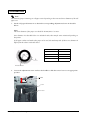
Paper Near-End Sensor
The diameter of the paper remaining on the roll paper can be detected at one of four levels by
the adjustment described below.
Rev. A
Adjustments and Settings 2-1
Confidential
Note:
The amount of paper remaining on roll paper varies depending on the outer and inner diameters of the roll
paper core.
1. Set the roll paper diameter A to obtain the corresponding adjustment shown in the table
below.
Note:
The inner diameter of the paper core should be 10 mm {0.4 in.} or more.
Since diameter A in the table below is a calculated value, there may be some variations depending on
the printer.
If roll paper with an end mark at the paper end is used, the mark may stick. If this occurs, diameter A
differs from the values in the table below.
A
Position
Approx. 10 mm
#1
Approx. 8.5 mm
#2
Approx. 7 mm
#3
Approx. 5 mm
#4
inner diameter
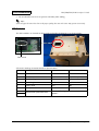
2. Loosen the adjustment screw and use the handle to slide the sensor lever to an appropriate
position.
handle
screw
sensor lever
2-2 Adjustments and Settings
Rev. A
Confidential
TM-J7000/TM-J7100 Developer’s Guide
3. Be sure that the sensor lever operates smoothly after setting.
Note:
If the roll paper becomes loose due to the paper quality, the near-end sensor may operate incorrectly.
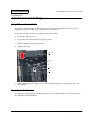
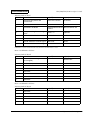
DIP Switches
The DIP switches are located on the main board inside the bottom cover of the printer.
DIP switch
DIP Switch Settings for Serial Interface Specifications
SW 1
Function
On
Off
1
Reserved
--
Fixed to Off
2
Interface condition selection
By DIP switch
By memory switch
3
Handshaking
XON/XOFF control
DTR/DSR control
4
Word length
7 bits
8 bits
5
Parity check
Yes
No
6
Parity selection
Even
Odd
Transmission speed selection
See the following table “Transmission
Speed.”
7
8
Rev. A
Adjustments and Settings 2-3
Confidential
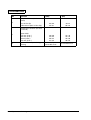
Transmission Speed
Transmission speed (bps)
SW1-7
SW1-8
9600
On
On
19200
Off
On
38400
On
Off
115200
Off
Off
bps: bits per second
Note:
Changes in DIP switch settings are recognized only when the printer power is turned on or when the
printer is reset by using the interface. If a DIP switch setting is changed after the printer power is turned
on, the change does not take effect until the printer is turned on again or is reset.
DIP Switch Settings for Parallel Interface specifications
SW 1
Function
On
Off
1~8
Reserved
--
Fixed to Off
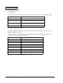
Memory Switches
The printer unit has the following memory switches in NV memory.
•
Memory switches: MSW1, MSW2, MSW8
•
Customized value
•
Serial communication conditions
These settings can be set by using the ESC/POS command GS ( E, or the Memory Switch Setting
Utility. For detail of the ESC/POS command, see the ESC/POS Application Programming
Guide. For details about the utility, see the user’s manual for the utility.
Some of these settings also can be set by panel operation (Memory switch setting mode). (See
“Memory switch setting mode” on page 7.)
Msw 1 is defined as follows:
2-4 Adjustments and Settings
Rev. A
Confidential
TM-J7000/TM-J7100 Developer’s Guide
Memory Switch Msw 1
Bit
Function
0 (Off)
1 (On)
1
Transmits the power ON
information
Does not transmit
Transmits
2
Reserved
--
--
3
Conditions for BUSY
Receive buffer-full or
Receive buffer-full
offline
4
Data processing for receiving
error
Prints "?"
Ignored
5
Automatic line feed
Disabled
Enabled
6
Connection of DM-D
Not connected
Connected
7
Pin #6: Selection of reset signal
Not used
Used
8
Pin #25: Selection of reset signal Not used
Used
NOTE:Msw 1-7 and 1-8 are effective only when the serial interface is used.
Msw 2 is defined as follows:
Memory Switch Msw 2
Bit
Function
0 (Off)
1 (On)
1
Reserved (the setting must not
be changed)
--
Fixed to On.
2
Autocutter operation
Disabled
Enabled
3
Reserved
--
--
4
Reserved
--
--
5
Reserved
--
--
6
Reserved
--
--
7
Reserved
--
--
8
Reserved
--
--
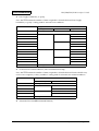
Msw 8 is defined as follows:
Memory Switch Msw 8
Bit
Function
0 (Off)
1 (On)
1
Reserved
--
--
2
Reserved
--
--
3
Reserved
--
--
4
Reserved
--
--
5
Reserved
--
--
Rev. A
Adjustments and Settings 2-5
Confidential
Bit
Function
0 (Off)
1 (On)
Slip print columns (for font A /
font B)
6
Face of the slip
Endorsement (back of the slip)
48 / 64
46 / 61
52/ 72
50 / 69
30 / 40
36 / 48
40 / 53
42 / 56
32 / 45
39 / 54
43 / 60
46 / 64
Receipt print columns (for font
A / font B)
7
8
Paper width
57.5 mm {2.26"}
69.5 mm {2.74"}
76 mm {2.99"}
82.5 mm {3.25"}
Paper roll cover open during
printing
2-6 Adjustments and Settings
Automatically
recoverable error
Recoverable error
Rev. A
Confidential
TM-J7000/TM-J7100 Developer’s Guide
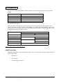
Customized value is defined as follows:
Customized Value
Item
Value
57.5 mm {2.26"}
Paper width selection
69.5 mm {2.74"}
76 mm {2.99"}
82.5 mm {3.25"}
Communication conditions for the serial interface are defined as follows:
Communication Conditions for the Serial Interface
Item
Value
2400 bps
4800 bps
9600 bps
Baud rate
19200 bps
38400 bps
57600 bps
115200 bps
None
Parity
Odd
Even
Handshaking
Data length
DTR/DSR control
XON/XOFF control
7 bits
8 bits
Memory switch setting mode
In the Memory switch setting mode you can set some Memory switches using printer buttouns.
This mode can set following settings.
❏ Enable or disable autocutter operation (Msw 2-1)
❏ Set the communication condition of the serial interface (Communication conditions for the
serial interface)
❏ Setting the conditions for communication
•
Rev. A
Conditions for BUSY (Msw1-3)
Adjustments and Settings 2-7
Confidential
•
Data processing for receiving error (Msw1-4)
❏ Automatic line feed (Msw 1-5)
❏ Interface reset signal (Msw1-7, Msw1-8)
Starting the memory switch setting mode
Use the following procedure to start the memory switch setting mode.
1. Open the roll paper cover.
2. Turn the power on while pressing the paper FEED button until the POWER, ERROR, and
PAPER OUT LEDs are all on.
3. Press the FEED button twice while POWER, ERROR, and PAPER OUT LEDs are on.
4. Close the roll paper cover.
The printer is now in the memory switch setting wait mode.
5. Press the FEED button. The printer prints the enabled settings of the memory switches and
instructions.
6. Follow the instructions to make the switch settings.
Ending memory switch setting mode
Once the setting is performed, the contents of the setting are stored. Then the printer initializes.
When initialization is finished, the printer returns to normal operating mode.
2-8 Adjustments and Settings
Rev. A
Confidential
TM-J7000/TM-J7100 Developer’s Guide
Operating procedure
The procedures used for this process are described below.
Entering Memory Switch Setting Mode
1. Open the roll paper cover and turn the power on while pressing the paper FEED button until
POWER, ERROR, and PAPER OUT LED are on.
2. Press the paper FEED button twice while POWER, ERROR, and PAPER OUT LED are on.
3. Close the roll paper cover.
4. Press the paper FEED button.
The printer prints the current settings and setting instructions.
Selecting Items to Set
Open the roll paper cover.
Press the FEED button the number of times required to select the desired item (as shown below);
then close the roll paper cover.
Pressing the paper FEED button 0 times or 7 or more times and then cloxing the cover will
terminate this procedure.
❒
❒
❒
❒
1 time:
3 times:
4 times:
6 times:
Autocutter
Basic Serial Interface Settings
Advanced Interface Settings
Interface Reset Signal
❒ 0 times:
❒ 2 times:
❒ 7 or more times: Unused
Selecting Individual Settings
Open the roll paper cover.
Press the FEED button the number of times required to select the setting for each item; then
close the paper roll cover.
Autocutter
(page 2-10)
Basic Serial Interface
Baud Rate Setup
(page 2-10)
Advanced
Interface
Setting
(page 2-10)
Automatic
Line Feed
(page 2-11)
Interface reset
signal
(page 2-12)
Data Length,
Handshake, or Parity
(page 2-11)
Ending Memory Switch Setting Mode
The printer prints the new settings and saves the settings to NV memory. Then, the printer is reset
and enter the normal printable status. Begin using the printer or turn the power supply OFF.
Rev. A
Adjustments and Settings 2-9
Confidential
Selecting individual settings
❏ Autocutter
Press the FEED button the number of times required to select the desired Autocutter setting.
Press FEED button
Setting to select
0 times:
No change
1 time:
Autocutter enabled
(Note: “Installed” is printed in the setting guidance)
2 times:
Autocutter disabled
(Note: “Not installed” is printed in the setting guidance)
3 or more times:
No change
❏ Basic serial interface setting
To select transmission conditions, first choose “Serial interface settings”; then select “Data
length, handshake, or parity.”
Press the FEED button the number of times required to select the desired “Serial interface
settings” used for transmission conditions.
Press FEED button
Setting selected
0 times:
No change
1 time:
115200 bps
2 times:
57600 bps
3 times:
38400 bps
4 times:
19200 bps
5 times:
9600 bps
6 times:
4800 bps
7 times:
2400 bps
8 or more times:
No change
bps: Indicates the number of transmitted bits per second (bps).
2-10 Adjustments and Settings
Rev. A
Confidential
TM-J7000/TM-J7100 Developer’s Guide
❏ Data length, handshake, or parity
Press the FEED button the number of times required to select the desired “Data length,
handshake, or parity” setting used for transmission conditions.
Press FEED button
Setting selected
Data Length
0 times:
No change
1 time:
8 bits
Handshake
Parity
DTR/DSR control
None
2 times:
Even
3 times:
Odd
4 times:
XON/XOFF control
None
5 times:
Even
6 times:
Odd
7 times:
7 bits
DTR/DSR control
None
8 times:
Even
9 times:
Odd
10 times:
XON/XOFF control
None
11 times:
Even
12 times:
Odd
13 or more times:
No change
❏ Transmission-related conditions (Advanced Interface Setup)
Press the FEED button the number of times required to select the desired “Receive buffer size,
receive error sequence, or busy condition” setting used for transmission-related conditions.
Press FEED button
Setting selected
Receive error sequence
0 times:
No change
1 time:
Change to '?'
2 times:
3 times:
Offline or receive buffer full
Receive buffer full
Ignore
4 times:
5 or more times:
BUSY condition
Offline or receive buffer full
Receive buffer full
No change
❏ Automatic line feed (CR command function)
Rev. A
Adjustments and Settings 2-11
Confidential
Press the FEED button the number of times required to select the desired auto carriage return
setting.
Press FEED button
Setting select ed
0 times:
No change
1 time:
Enabled
2 times:
Disabled
3 or more times:
No change
❏ Interface reset signal
Pins #25 and #6 on the RS-232 I/F circuit board unit (UB-S01/02) are used to input the reset
signal. This item is used to "Enable (acknowledge)" or "Disable (not acknowledge)" input of the
reset signal from one of these pins. Press the FEED button the number of times required to select
the desired interface reset signal setting.
Press FEED button
Setting selected
Pin #25
0 times:
No change
1 time:
Disabled
2 times:
Pin #6
Disabled
Enabled
3 times:
Enabled
4 times:
Disabled
Enabled
5 or more times:
No change
Connection Form and Cables
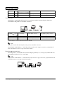
Serial Connection
When the TM printer is connected to the host PC with a serial interface, the following connection
forms are possible:
•
Stand alone
•
Y-connection
•
Pass-through connection
2-12 Adjustments and Settings
Rev. A
Confidential
TM-J7000/TM-J7100 Developer’s Guide
Connections for usable serial cross cables are as follows:
The type of cable that should be used depends on the operation and the handshake method for
the TM printer. You can operate the TM printer with the Windows driver, OPOS, or ESC/POS
commands. XON/XOFF, DTR/DSR, or RTS/CTS are available as handshake controls. See tables
in the following sections for the cable type for each connection.
Stand alone
Both TM printer and customer display (DM-D) are connected to the host PC via serial port.
2
1
Application XON/XOFF
TM side
control
control setting
XON/XOFF
Rev. A
1
(except OPOS)
Type A or B
DTR/DSR
(DOS, OPOS, Visual C)
—
RTS/CTS
(DOS, Windows driver, Visual C,
Visual Basic, MSComm)
—
Adjustments and Settings 2-13
Confidential
DTR/DSR
2
DM-D500: A,B
Other DM-D: not available
—
—
1
—
Type A or B
Type B
2
—
Type A or B
Type B
Y-connection
TM printer is connected to the host PC via serial port and the customer display (DM-D) is
connected to TM printer via modular connector.
Application
TM side
control
control setting
XON/XOFF
XON/XOFF
(except OPOS)
DTR/DSR
(DOS, OPOS, Visual C)
RTS/CTS
(DOS, Windows driver, Visual C,
Visual Basic, MSComm)
Not available
—
—
—
Type B (*)
Type B
DTR/DSR
(*) When RTS/CTS control is used between the TM and DM.
Note:
You need to use the UB-S09 interface when you use a modular connector.
On the DM-D (DM-D500 etc...) which has a DIP switch to select Y-type connection, confirm that the
DIP switch has been set to “Y-type connection: Enable.”
Pass-through connections
The TM printer is connected to the customer display (DM-D) via a serial port, and the DM-D is
connected to the host PC via a serial port.
Note:
On the DM-D (DM-D500 etc...) which has DIP switch to select Y-type connection, confirm that the DIP
switch has been set to “Y-type connection: Disable.”
2-14 Adjustments and Settings
Rev. A
Confidential
TM-J7000/TM-J7100 Developer’s Guide
Application XON/XOFF
TM side
control
control setting
XON/XOFF
DTR/DSR
(except OPOS)
DTR/DSR
(DOS, OPOS, Visual C)
RTS/CTS
(DOS, Windows driver, Visual C,
Visual Basic, MSComm)
Not available
—
—
1
—
Type A or B
Type B
2
—
Type A or B
Type A or B
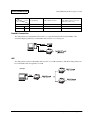
Parallel Connection
The TM printer is connected to the host PC via a parallel interface board (UB-P02II). The
customer display (DM-D) is connected to the host PC via a serial port.
USB
The TM printer can be connected to the host PC via a USB connector, and other TM printers can
be connected to the first printer via USB.
Example:
(UB-U02II)
(UB-U01II)
(UB-U02II)
Rev. A
Adjustments and Settings 2-15
Confidential
Ethernet
TM printers are connected to a network via a hub using an Ethernet cable.
Note:
If the TM printer is connected to the host PC via the Ethernet interface, a DM-D cannot be connected to
the TM printer.
2-16 Adjustments and Settings
Rev. A
Confidential
TM-J7000/TM-J7100 Developer’s Guide
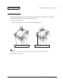
For IBM POS systems
When installing this printer on an IBM POS system (IBM Sure POS 700 series, or IBM 4694
models 041, 044, and 144), follow the procedure below.
1. Remove the rubber feet.
2. Install new rubber feet as shown in the following illustration.
Remove these rubber feet.
Install new rubber feet here.
Note:
You can get rubber feet separately by using the part numbers in the brackets as follows.
❏ Rubber foot <1075187>
Rev. A
Adjustments and Settings 2-17
Confidential
2-18 Adjustments and Settings
Rev. A
Confidential
TM-J7000/TM-J7100 Developer’s Guide
Chapter 3
Application Development Information
This section explains key words and miscellaneous information in a question and answer format
and the single-pass processing for developing a system with the TM-J7000/J7100.
Rev. A
Application Development Information 3-1
Confidential
Key words in Q & A
Category
Question
Answer
What is an active sheet?
Any one of the types of paper the printer can
process, such as roll paper, a slip sheet, or a
check.
Why the active sheet is
selected?
To select the functions the printer can use. For
example, roll paper requires certain functions
that the other types of paper do not require.
GS ( G function 80 selects the active sheet.
For the following actions, the active sheet will
be selected automatically without being
selected by GS ( G function 80.
• A print sheet will automatically
be the active sheet when a print
sheet selected by ESC c 0.
•
Check will automatically be the
active sheet when FS a 0 (read
check paper) is executed
•
Slip will automatically be the
active sheet when FS a 1 (Load
check paper to print starting
position) is executed.
•
Slip will automatically be the
active sheet when GS ( G
function 48 (Specifies slip as the
paper type and the side to be
printed) is executed.
•
Roll paper is will automatically
be the active sheet when the slip
is ejected by FF (Print and eject
cut sheet) after printing on the
slip.
•
Roll paper is will automatically
be the active sheet when a cut
sheet is release by ESC q is
executed.
•
Roll paper is will automatically
be the active sheet when a check
is ejection by FS a 2 is executed.
Active sheet
What commands are
related to the active sheet?
3-2 Application Development Information
Rev. A
Confidential
Category
Active sheet
Print sheet
and print side
TM-J7000/TM-J7100 Developer’s Guide
Question
Answer
When do you need to select
the active sheet with GS ( G
function 80?
Before image scanning you need to select a
check as the active sheet.
A check is automatically
selected as the active sheet
with FS a 0, read check
paper; however the check is
not selected automatically
by GS ( G function 65
when reading an image of
a check. Why?
The current command, FS a 0 has multiple
functions so that it automatically selects the
active sheet; then reads the MICR; however GS
( G function 65 has only one function so that
there is flexibility of command combination,
which follows the policy of the ESC/POS that
one command has one function.
What is the difference
between GS ( G function
48, select slip as the paper
type and the side of the
sheet to be printed, and
ESC c 0, select paper
type(s) for printing?
Print sheet and print side to be selected are
different. GS ( G function 48 is exclusively for
a slip, selecting surface or back of the sheet,
not for selecting roll paper. After executing FS
a 0, read check paper, even if GS ( G function
48 is executed, the slip will not be ejected;
therefore, it is possible to check the single-pass
processing.
ESC c 0 can select roll paper or the surface of a
slip; however the back of the slip cannot be
selected. After executing FS a 0, read check
paper, if the slip is selected by ESC c 0, the slip
is ejected and the printer will be in the slip
insertion waiting state.
FS a 0, FS a 1, FS a 2 are obsolete commands; therefore, we recommend using other
commands instead of these commands. See following descriptions.
Obsolete command
There are more suitable substitute commands for the following commands. These obsolete commands will
not be supported by future printer models. More suitable substitute commands follow.
GS ( G <Function 60> is a substitute for FS a 0
GS ( G <Function 48> and GS ( G <Function 84> are a substitute for FS a 1
GS ( G <Function 85> is a substitute for FS a 2
GS V is a substitute for ESC i and ESC m
GS r is a substitute for ESC u and ESC v
GS ( C is a substitute for FS g 1 and FS g 2
GS ( L is a substitute for FS p and FS q
Rev. A
Application Development Information 3-3
Confidential
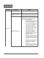
Miscellaneous Information in a Q & A Format
The following Q & A will help you understand more about the printer.
Question
Answer
What happens when an ink out occurs?
The printer prints all data in the line being
printed when the ink out signal is received;
then it stops printing.
With two ink cartridges (main color and sub
color), how does the printer work if only
one cartridge is empty?
The printer stops printing. If either one of
the ink cartridges is empty, it is impossible
to continue printing.
If one color is never used for printing, the
color ink isn’t consumed?
No. Even if one color is never used, both ink
head nozzles are cleaned periodically. The
cleaning consumes a small amount of ink.
Disposed ink absorption material is
provided only for the sub color side. if only
the main color is used frequently, might the
capacity of the ink absorption material
exceed its tolerance?
No. If the only the main color is used
frequently, cleaning of the sub color is also
performed, which reduces the sub color ink.
If the sub-color is never used for printing
and all ink is used only by cleaning while
the main color ink is replaced a few times,
there will be enough disposed ink
absorption material capacity until the sub
color ends.
What happens when a pump unit reaches
the end of its life (when a message of pump
unit life end is printed)?
The life of the pump unit is approximately
twice as much as that of the printer; usually
the pump unit will last 10 years.
What is the method of extending the
printing area on a slip in page mode?
You should use the Function 48 of the
GS(P command.
A. Adjust the horizontal offset of page
mode to the edge of your designed
printing area.
B. Choose single color using the parameter
c.
3-4 Application Development Information
Rev. A
Confidential
TM-J7000/TM-J7100 Developer’s Guide
Single-Pass Processing
EPSON recommends the following sequence of MICR reading, endorsement printing, and
printing on front for single-pass processing.
Step
User Operation
Printer Operation
1
Transmit GS ( G <Function 80>
[GS ( G 2 0 80 32]
Selects the check as the paper source.
2
Transmit GS ( G <Function 83>
[GS ( G 2 0 83 48]
Waits for a cut sheet to be loaded.
The CUT SHEET LED flashes
3
Insert a cut sheet. (*1)
Clamps the cut sheet when it is detected. The
CUT SHEET LED flashes.
4
Transmit GS ( G <Function 60>
[GS ( G 4 0 60 1 0 m]
Reads MICR characters and transmits the
reading status. m specifies the type of MICR
characters.
(m = 0: E13B / m = 1: CMC7)
5
Transmit GS ( G <Function 48>
[GS ( G 2 0 48 68]
Selects the back of the slip (cut sheet) as the
paper source. (The back of the cut sheet which
has been read for MICR becomes the side to be
printed.)
6
Transmit GS ( G <Function 84>
[GS ( G 2 0 84 1] (*3)
Feeds the print starting position on the back of
the slip (cut sheet).
7
Transmit endorsement printing
data.
Prints data on the back of the cut sheet and
feeds the cut sheet.
8
Transmit GS ( G <Function 48>
[GS ( G 2 0 48 4]
Selects the face of the slip (cut sheet) to be
printed. (The face of the cut sheet which has
been read becomes the side to be printed.)
9
Transmit GS (G <Function 84>
[GS (G 2 0 84 1] (*3)
Feeds the print starting position on the face of
the cut sheet.
10
Transmit cut sheet printing data
Prints on the face of the cut sheet and feeds
the cut sheet.
11
Transmit GS ( G <Function 85>
[GS ( G 2 0 85 m]
Ejects or releases the cut sheet, and selects the
paper roll as the paper source. m specifies the
type of operation (m = 48: eject / m = 49:
release) The CUT SHEET LED flashes.
12
Remove the cut sheet. (*2)
The CUT SHEET LED is off.
(*1) Insert the cut sheet correctly by aligning the upper and right side of the cut sheet with the
upper and right side of the printer's paper insertion position and inserting it until it is
stopped by the form stopper.
The cut sheet insertion waiting state is canceled using DLE ENQ (n = 3).
The cut sheet waiting time and the interval from when a cut sheet is inserted to when the
operation starts can be set using ESC f.
Rev. A
Application Development Information 3-5
Confidential
(*2) After processing GS ( G <Function 85>, the printer flashes the CUT SHEET LED and does
not take the next action until the paper is removed.
(*3) The print starting position can be set once per each printing of face of the slip.
NOTE:
The following shows the paper position and paper feeding directions for the single-pass processing. The
number of the picture corresponds to the number of the step in the table above.
❏ You can omit the processes you do not need.
Example: You can omit steps 5, 6, and 7 if you are not doing endorsement printing.
You can omit steps 8, 9 and 10 if there is handwriting on the surface side.
❏ For details of the commands and the programming samples, see the ESC/POS Application
Programming Guide.
The following shows the paper position and paper feeding directions for the single-pass
processing. The number of the picture corresponds to the number of the step in the table above.
3-6 Application Development Information
Rev. A
Confidential
TM-J7000/TM-J7100 Developer’s Guide
CLAMP
2. The cut sheet is inserted.
3. The cut sheet has been clamped when
the it was detected.
4-1. MICR reading is performed.
4-2. MICR reading is completed.
Rev. A
Application Development Information 3-7
Confidential
6. Feeds the cut sheet to the print start
position of the back.
7. Prints endorsement.
9. Feeds the cut sheet to the print start
position of the face.
10. Prints on the face of the cut sheet and
feeds the cut sheet.
3-8 Application Development Information
Rev. A
Confidential
TM-J7000/TM-J7100 Developer’s Guide
11. Ejects the cut sheet.
Rev. A
Application Development Information 3-9
Confidential
3-10 Application Development Information
Rev. A
Confidential
TM-J7000/TM-J7100 Developer’s Guide
Chapter 4
Specifications
Product Specifications
Item
Specifications
Printing method
Serial ink jet dot matrix
Paper width
Roll paper: 82.5 ± 0.5 mm, 76 ± 0.5 mm, 69.5 ± 0.5 mm, 57.5 ± 0.5 mm
Autocutter
Circular-type cutting method
One point left uncut (partial cut)
Connector
Interface connector, power connector, drawer kick connector,
DM-D connector (Available only for the serial interface model)
Switch and Button
Power switch, paper feed Button, cleaning Button
LED
Power LED, Error LED, Ink out LED, Paper out LED, Cut sheet LED
Reception buffer
4 kbytes
Download buffer
12 kbytes for both download characters and download bit images
NV graphics and user NV
memory
384 kbytes
Power supply
Power supplied by AC adapter PS-180 (option)
Operating voltage
24V±2.4V
Current consumption
(excluding drawer kick
drive)
Operating: Mean: Approximately 0.5A
(Printing alphanumeric characters in font A, all columns)
Peak: Approximately 2.7A
Standby: Mean: Approximately 70 mA
External dimensions
188 × 195 × 237 mm (H × W × D)
Weight (mass)
Approximately 4.4 kg
Rev. A
Specifications 4-1
Confidential
Print Specifications
Item
Specifications
Print method
Serial inkjet dot matrix
Head nozzle array
TM-J7000
64 nozzles ✕ 1 line
Nozzle pitch approx. 0.141 mm (1/180 inch)
TM-J7100
64 nozzles ✕ 2 lines (one line for each color)
Nozzle pitch approx. 0.141 mm (1/180 inch)
Printing direction
Bidirectional logical seeking
Paper feed
See each printer section
Printing width (Roll paper)
See each printer section. (roll paper printer, slip printer, and
endorsement printer)
Character count
See each printer section. (roll paper printer, slip printer, and
endorsement printer)
Printing speed
See “Print Speed.” table.
Paper feed speed
Approx. 150 mm/s (approx. 5.9 inches/s) at 35.4 lps
(lps: lines per second)
Print Control mode
See “Print Control Modes.” table. Normal, high-speed, or economy
mode can be set using software commands.
Line spacing
Approx. 4.23 mm or 1/6 inch (default)
3.18 mm (1/8 inch) (when printing 3 lines at a time)
Set using software commands
Print Control Modes
Print mode
Number of
carriage
passes (*1)
Vertical
resolution
[dpi]
Horizontal
resolution
[dpi]
Dot structure
(number of pulses
to the head)
Name
Description
Normal
Offers high-density (high
quality) printing.
1
180
180
6
High-speed
Features high-speed
printing and ink saving. (Is
the default mode)
1
180
180
3
Economy
Features even greater ink
saving than high-speed
mode.
1
180
180
2
[dpi: Dots per inch (25.4 mm) {1”} ]
(*1) Pass: To move the carriage from the left to the right or from the right to the left.
4-2 Specifications
Rev. A
Confidential
TM-J7000/TM-J7100 Developer’s Guide
.
Print Speed
Print mode
Normal
High-speed
Economy
Font
Unit
Paper width (mm)
Slip
57.5
{2.26”}
69.5
{2.74”}
76
{2.99”}
82.5
{3.25”}
Font A (6 lpi)
lps
7.4
6.7
6.3
6.0
6.0
Font B (8 lpi)
lps
10.7
9.5
8.9
8.6
8.6
Graphics
mm/s
32
29
27
26
26
Font A (6 lpi)
lps
11.6
10.5
10.1
9.7
9.6
Font B (8 lpi)
lps
16.4
15.0
14.3
13.8
13.7
Graphics
mm/s
50
45
43
41
40
Font A (6 lpi)
lps
11.6
10.5
10.1
9.7
9.6
Font B (8 lpi)
lps
16.4
15.0
14.3
13.8
13.7
Graphics
mm/s
50
45
43
41
40
Note:
All values listed above are the printing speed without character modification when the printing is
performed continuously for all columns without cleaning.
Printing speed may be slower, depending on the data transmission speed and the combination of control
commands. If the data transmission speed is slow, the printing becomes intermittent. Therefore, it is
recommended to use high-speed data transmission.
Rev. A
Specifications 4-3
Confidential
Character Specifications
Character Specifications
Item
Specifications
Character type
Alphanumeric
95 characters
International
37 types
Extended graphics
128 characters ✕ 11 pages
(including one user-defined page)
Character structure
See "Character Configurations and Dimensions" table
below. (Default is Font A.)
Character dimensions
See "Character Configurations and Dimensions" table
below. (Spaces between characters not included.)
Character structure
Dot configuration
H ✕ V (includes 2-dot H space)
Font A
Font B
* Font A
* Font B
12 ✕ 24
9 ✕ 17
11 ✕ 24
8 ✕ 17
* : Using the memory switch for characters per line
Note:
The number of characters (columns) per line is selectable by a memory switch.
Selection of characters per line can be performed for receipt and slip (including endorsement).
If memory switch changing of characters per line is performed, one dot on the right side of a graphic
character or user-defined character may be missed.
Character size
Standard
Double-height
Double-width
Double-width /
Double-height
W × H (mm)
W × H (mm)
W × H (mm)
W × H (mm)
Font A (12 × 24)
1.69 × 3.38
1.69 × 6.77
3.38 × 3.38
3.38 × 6.77
Font B (9 × 17)
1.27 × 2.40
1.27 × 4.80
2.54 × 2.40
2.54 × 4.80
* Font A (11 × 24)
1.55 × 3.38
1.55 × 5.77
3.10 × 3.38
3.10 × 6.77
* Font B (8 × 17)
1.13 × 2.40
1.13 × 4.80
2.26 × 2.40
2.26 × 4.80
The actual print character may be smaller than the size shown in the table above, because the above size includes
spaces in the font.
Characters can be scaled up to 64 times as large as the standard size.
Character size not including the horizontal spacing in the standard scale is as follows:
Font A:1.41 (W) × 3.384 (H) mm
Font B: 0.987 (W) × 2.397 (H) mm
4-4 Specifications
Rev. A
Confidential
TM-J7000/TM-J7100 Developer’s Guide
Receipt Printer Section
Characters per Line and Printable Area for Roll paper
Paper roll width (mm)
57.5
{2.26”}
69.5
{2.74”}
76
{2.99”}
82.5
{3.25”}
Number of dots for printing (dots)
360
432
480
512
Printable width (mm)
50.8
{2.00”}
61
{2.40”}
67.7
{2.67”}
72.2
{2.84”}
Font A (12 × 24)
30
36
40
42
When printing at 15 cpi
Font B (9 × 17)
40
48
53
56
When printing at 20 cpi
* Font A (11 × 24)
32
39
43
46
When printing at 16.3 cpi
* Font B (8 × 17)
45
54
60
64
When printing at 22.5 cpi
Characters per line
Remarks
*: Selectable be a memory switch
[cpi: Characters per inch (25.4 mm) {1”} ]
Paper Feed Specifications
Paper Feed Specifications
Item
Specifications
Paper feed method
Friction feed
Paper feed direction
Unidirectional
Feeding pitch
Min. approx. 0.1411 mm (1/180 inch)
Continuous feed speed
Approx. 150 mm/s (approximately 5.9 inches/s) at 35.4 lps
lps: lines per second
Rev. A
Specifications 4-5
Confidential
Printable Area
c
ABCDE
12345
567890
b
Paper feed direction
d
Printing area
a
Paper roll width
Printable Area
Dimensions
a (paper roll width)
b (left margin)
c (printing area)
d (right margin)
57.5 {2.26”}
3.4 {0.13”}
50.8 {2.00”} (360 dots)
3.3 {0.13”}
69.5 {2.74”}
4.2 {0.17”}
61.0 {2.40”} (432 dots)
4.3 {0.17”}
76 {2.99”}
4.3 {0.17”}
67.7 {2.67”} (480 dots)
4.2 {0.17”}
82.5 {3.25”}
6.0 {0.24”}
72.2 {2.84”} (512 dots)
4.3 {0.17”}
4-6 Specifications
Rev. A
Confidential
TM-J7000/TM-J7100 Developer’s Guide
Printing Position Versus Cutter Position
The printing position in relation to cutter position is shown in the figure below.
Position to be left
uncut
Last line of previous receipt
Emergency cutter position
Approx. 34 mm
{1.34”}
Auto cutting position
See Note below
Approx. 20 mm
{0.79”}
Printing area
Paper feed direction
Printing Position Versus Cutter Position
Note:
Numeric values used here are typical values; the values may vary slightly as a result of paper slack or
variations in the paper. Take this note into account when setting the cutting position of the autocutter.
Slip Printer Section
Characters per Line and Printable Area for Slips
Number of dots for printing (dots)
576
Printable width (mm)
81.3 {3.20”}
Characters per line
Font A (12 × 24)
48
When printing at 15 cpi
Font B (9 × 17)
64
When printing at 20 cpi
* Font A (11 × 24)
52
When printing at 16.3 cpi
* Font B (8 × 17)
72
When printing at 22.5 cpi
*: Selectable be a memory switch
Rev. A
Specifications 4-7
Confidential
Paper Feed Specifications
Paper Feed Specifications
Item
Specifications
Paper feed method
Friction feed
Paper feed direction
Bidirectional
Feeding pitch
Approx. 0.1411 mm (1/180 inch)
Continuous feed speed
Approx. 150 mm/s (approximately 5.9 inches/s) at 35.4 lps
lps: lines per second
The first printing
line position
Form stopper
position
36 (255 steps)
Printable Area
TOF sensor position
The last printing line
position
63.4 (449 steps)
Paper feeding
roller position
BOF sensor position
[Units: mm]
Printable area
Note:
The values shown in this figure are calculated ones. Consider this for the user design for the print starting
position in the paper feeding direction.
4-8 Specifications
Rev. A
Confidential
TM-J7000/TM-J7100 Developer’s Guide
MICR Reader Section (Factory-Installed Option)
Reading Method
Permanent magnetic bias
Recognition Rate
98% or more at 25°C {77°F}
Recognition rating is defined as follows
Total number of checks − (number of sheets misread or not identified.)
Recognition rating (%)=
× 100
Total number of checks
Rev. A
•
Check paper used for test is EPSON standard check paper.
•
Checks must be flat, without curls, folds, or wrinkles.
Specifications 4-9
Confidential
Insertion Direction and Endorsement Printing
46.0 {1.81"}
Area where recognition is
impossible.
Insert the check with the surface printed with the magnetic ink facing upward, following the slip
side guide.
Insertion
direction
Area of Personal Check where MICR Character Recognition is Impossible
Notes on Using the MICR Reader
❏ Do not install the printer near any magnetic fields, because this may cause MICR reading
errors. (Especially when the printer is used near the display device, the user must check the
recognition rate of the MICR.)
❏ The MICR characters may not be recognized when impact or vibration is applied to the
printer.
❏ Multiple fold checks are not supported.
❏ The personal checks must be flat, without curls, folds, or wrinkles (especially at the edges).
Otherwise, the check may rub against the nozzles and become ink-stained.
❏ Do not insert checks that have clips or staples. These may cause paper jams, MICR reading
errors, and damage to the MICR head.
4-10 Specifications
Rev. A
Confidential
TM-J7000/TM-J7100 Developer’s Guide
❏ Let go of the check immediately as soon as the printer starts feeding it. Otherwise, the paper
is not fed straight, causing paper jams and MICR reading errors. Also, do not open any
covers.
Endorsement Mechanism Section (Factory-Installed Option)
The endorsement mechanism enables printing of endorsements as part of a sequence that is
automatically processed: MICR reading, printing an endorsement on the back of the personal
check, and printing on the face of the check.
Characters per Line and Printable Area for Endorsement (Factory- installed Option
Number of dots for printing (dots)
552
Printable width (mm)
7739 {3.06”}
Characters per line
Font A (12 × 24)
46
When printing at 15 cpi
Font B (9 × 17)
61
When printing at 20 cpi
* Font A (11 × 24)
50
When printing at 16.3 cpi
* Font B (8 × 17)
69
When printing at 22.5 cpi
*: Selectable be a memory switch (same as the setting for slip)
Printable Area
Max.78 mm (525 dot position)
38.1 mm
Approximately 29.6 mm
(210 dot position)
5 mm
Endorsement
printable area
5 mm
Printable Area for Endorsement Printing
Rev. A
Specifications 4-11
Confidential
Note:
The values shown in this figure are calculated ones. Consider this for the user design for the print starting
position in the paper feeding direction.
Notes on Using the Endorsement Mechanism
❏ The endorsement mechanism enables printing of endorsements on the back of a personal
check. Do not use paper that is over 101.6 mm {4"} in width. Otherwise, paper may be
jammed.
❏ Do not open any covers while the sequence of check reading and endorsement printing is
processed. Otherwise, the paper is not fed straight, causing paper jams and MICR reading
errors.
❏ Observe the same limitations as for slips for the position of paper holes and the reflection
ratio of the check.
15
30
10
Area where paper holes are
prohibited and reflection
rate for the back of paper
should be 40% or more.
Paper feed direction
Paper holes and
translucence prohibited in
this area.
[Units: mm (All the numeric values are typical.)]
4-12 Specifications
Rev. A
Confidential
TM-J7000/TM-J7100 Developer’s Guide
Paper Specification
Paper Roll Specification
Paper type
Normal quality paper (only single-ply rolls can be used)
Form
Roll paper
Paper width
Can be selected an any of the following:
82.5 ± 0.5mm
76 ± 0.5mm
69.5 ± 0.5mm
57.5 ± 0.5mm
Paper thickness
0.06 ~ 0.09mm
Paper weight
52.3 ~ 64.0 g/m² {14 ~ 17 lb} (JIS P8124)
(45 ~ 55 kg / 1000pcs / 788mm × 1091mm)
Spool diameter
inside: 10mm {0.39”) or more
Roll paper diameter
Outside: 83mm {3.27”} or less
Slip Paper Specification
Paper type
Normal paper
Paper size
68 ~ 230mm (W) × 68 ~ 297mm (L) {2.7 ~ 9.1” (W) × 2.7 ~ 11.7” (L)}
* The minimum paper size is 68mm (W) × 152mm (L) {2.7” (W) × 6.0” (L)}
Paper thickness
0.09 ~ 0.2mm {0.0035 ~ 0.0079”} (only single-ply can be used)
Notes on slip paper
❏ The slip paper must be flat, without curls or wrinkles, especially at the top edges. Otherwise,
the paper may rub against the nozzles and become dirty.
❏ Since the slip BOF sensor uses a photo sensor, do not use paper that has holes at the sensor
position, or is translucent.
Rev. A
Specifications 4-13
Confidential
❏ Since the slip TOF sensor uses a reflective photo sensor and it detects from the back of slip
paper, do not use paper that has holes or dark portions with low reflection (less than 40%
reflection) at the sensor position.
15
30
10
Area where paper holes are
prohibited and reflection
rate for the back of paper
should be 40% or more.
Paper holes and
translucence prohibited in
this area.
Paper feed direction
[Units: mm (All the numeric values are typical.)]
Area with No Paper Holes and Low Reflection
Endorsement Paper Specification
Paper type
High- quality paper (only single-ply paper can be used)
Paper size
68 ~ 101.6mm (W) × 150 ~ 223mm (L)
Paper thickness
0.09 ~ 0.13mm {0.0035 ~ 0.0051”} (only single-ply can be used)
4-14 Specifications
{2.68 ~ 4.17” (W) × 5.90 ~ 8.98” (L)}
Rev. A