1
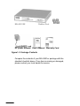
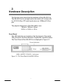
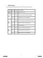
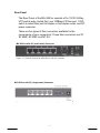
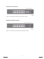
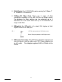
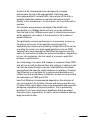
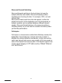
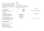
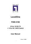
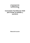
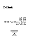
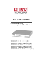
MIL-S501xx Series 5x 10/100 N-Way RJ-45 Ports plus One 100Base-FX fiber Port MIL-S501ST with ST connector (2km) MIL-S501SC with SC connector (2km) MIL-S501SC-15 with SC connector (15km) MIL-S501SC-30 with SC connector (30km) MIL-S501SC-60 with SC connector (60km) MIL-S501MT with MT-RJ connector (2km) MIL-S501MT-15 with MT-RJ connector (15km) COPYRIGHT 2005 ALL RIGHTS RESERVED. First Edition. Printed in China. All trademarks are the properties of their respective owners. No portion of this document may be reproduced, altered, adapted or translated without the prior written approval. DOCUMENT WARRANTY The information in this document is subject to change without notice. We make no warranty of any kind regarding this material, including, but not limited to, the implied warranties or merchantability and fitness for a particular purpose. Furthermore, we shall not be liable for errors contained herein or for incidental or consequential damage in connection with the furnishing, performance, or use of this material. FCC STATEMENT This equipment has been tested and found to comply with the limits for a Class A and B computing device, pursuant to part 15 of the FCC rules. These limits are designed to provide reasonable protection against harmful interference in commercial or residential environments. This equipment generates and radiates radio frequency energy and, if not installed and used in accordance with instructions, may cause harmful interference to radio communications. In which case, the user will be requires to correct the interference at the user’s own expense. Five-year Limited Warranty MiLAN Technology warrants to the original consumer or purchaser that each of its products and all components thereof, will be free from defects in material and/or workmanship for a period of five years from the original factory shipment date. Any warranty hereunder is extended to the original consumer or purchaser and is not assignable. MiLAN Technology makes no express or implied warranties including, but not limited to, any implied warranty of merchantability or fitness for a particular purpose, except as expressly set forth in this warranty. In no event shall MiLAN Technology be liable for incidental or consequential damages, costs, or expenses arising out of or in connection with the performance of the product delivered hereunder. MiLAN Technology will in no case cover damages arising out of the product being used in a negligent fashion or manner. Trademarks © 2005 MiLAN, the MiLAN logo and MiLAN Technology are either trademarks or registered trademarks of MiLAN Technology in the United States and/or other countries. All other Trademarks are the property of their respective holders. To Contact MiLAN Technology For prompt response when calling for service information, have the following information ready: Product serial number and revision, Date of purchase and Vendor or place of purchase. You can reach MiLAN Technology technical support MiLAN Technology at: E-mail: [email protected] 1329 Moffett Park Drive Telephone: +1.408.744.2751 Sunnyvale, CA 94089-1138 Fax: +1.408.744.2771 United States of America http://www.milan.com Telephone: +1.408.744.2775 [email protected] Fax: -1.408.744.2793 ©Copyright 2005 MiLAN Technology P/N 90000418_B 2 Contents 1. Introduction…….………………………….……….… 4 Features …………………………………………..….….…… 5 Package Contents ………………………..……………….... 6 2. Hardware Description …………………..…..……… 7 Front Panel …………………...……...………………….…… 7 LED Indicators …………………...……...…………..….…… 8 Rear Panel ……………………………………………………. 9 3. Network Application ……………..……….………… 12 Desktop Application …………………….…………...…..… 12 Collapsed Backbone Application ………………….…..… 13 4. Trouble Shooting .………………………..……….… 14 5. Technical Specification .……………….…..…...… 16 3 1. Introduction Welcome to the World of Micro-Networking. Communication and Sharing information is a crucial component of business today. The need for instant electronic communication between employees, vendors and customers, along with access to information sources and sharing of equipment, has necessitated connectivity to even the most remote office location. The MIL-S501xx is a compact desktop size switch that is an ideal solution for distributed network user. It provides wire-speed, Fast Ethernet switching function that allows high-performance, lowcost connection. The fiber port offerings allow for a selection to meet the most demanding of Fiber Fast Ethernet needs. F igure 1-1. The MIL-S501xx The Switch will automatically detect the speed of the device that you plug into it to allow you to use both 10 and 100Mpbs devices. The 10Mbps bandwidth will accommodate legacy devices such as hubs or printers, while simultaneously providing the 100Mbps bandwidth needed to accommodate multimedia applications. The Switch features a store-and-forward switching and it can autolearn and store source address on a 2K-entry MAC address table. The MIL-S501xx is a 5-port switch coupled with one 100Base-FX fiber port. There are 4 types of fiber connectors available for the convenience of your connectivity on the MIL-S501xxs. 4 These fiber connectors are ST, SC multi-mode, SC single-mode, and MT-RJ. The fiber port can be used to connect to a remote site up to 2 kilometers using multi-mode fiber or up to 60 kilometers with SC single-mode fiber. Features n n n n n n n n n n n n 5X 10/100Mbps Fast Ethernet UTP switch ports Auto MDI or MDI-X sensing on all ports One 100Mbps Fast Fiber port 1 Dip-Switch to select fiber port full-duplex or half-duplex mode N-Way auto-negotiation supported Full-duplex and half-duplex supported Store-and forward switching architecture for abnormal packet filtering Full wire speed forwarding rate 2K-entry MAC address table 96KB Memory Buffer LED-indicators for Power, 10/100M, LK/ACT, FD/COL statuses Compact palm size – 6.5” Package Content n n n n n MIL-S501xx Four Rubber Feet with adhesive pads One DC power adapter Warranty Card User’s Manual 5 MIL-S501XX Rubber Feet DC power Adapter User’s Manual Warranty Card Figure1-2. Package Contents Compare the contents of your MIL-S501xx package with the standard checklist above. If any item is missing or damaged, please contact your local dealer for service. 6 2. Hardware Description This Section mainly describes the hardware of the MIL-S501xx. The MIL-S501xx is a compact palm size switch (6.5 inches) with 5x 10/100 N-Way UTP switch ports plus one 100Baes-FX fiber port. The physical dimensions of the MIL-S501xx are: 165mm x 100mm x 24mm 6.50 in. x 3.94 in. x .95 in. Front Panel The LED indicators are located on the frond panel of the switch. They provide a real-time indication of systematic operation status. The Front Panel of the MIL-S501xx is displayed in Figure 2-1. Figure 2-1. The Front Panel of the MIL-S501xx 7 LED Indicators The following table provides descriptions of the LED statuses and meaning. LED Power Status Color Description On Green The power of unit is On On Green The port is operating at the speed of 100Mbps. Off In 10Mbps mode or no device attached 100M On LNK / ACT Blinks Off On FDX / COL Blinks Off Green The port is successfully connecting with the device. The port is receiving or transmitting data. No device attached. Yellow The port is operating in Full-duplex mode. Collision of Packets occurs in the port. Half-duplex mode or no device attached. 8 Rear Panel The Rear Panel of the MIL-S501xx consists of 5x 10/100 N-Way UTP switch ports, Uplink Port, one 100Base-FX fiber port, 1 DIPswitch to select fiber port full-duplex or half-duplex mode, and DC power connector. There are five types of fiber connectors available for the convenience of your connectivity. These fiber connectors are ST, SC MMF, SC SMF, and MT-RJ. MIL-S501xx with SC (multi-mode) Connector Figure 2-2. The Rear Panel of the MIL-S501xx with SC Connector MIL-S501xx with SC (single-mode) Connector Figure 2-3. The Rear Panel of the MIL-S501xx with SC (single-mode ) Connector 9 MIL-S501xx with ST Connector Figure 2-4. The Rear Panel of the MIL-S501xx with ST Connector MIL-S501xx with MT-RJ Connector Figure 2-5. The Rear Panel of the MIL-S501xx with MT-RJ Connector 10 n RJ-45 Ports: Five 10/100 N-Way auto-sensing for 10Base-T or 100Baes-TX connections. n 100Base-FX Fiber Port: There are 5 types of fiber connectors available for the MIL-S501xx as shown above. The distance for fiber cabling can be extended up to 2 kilometers for multi-mode fiber and up to 70 kilometers for single-mode fiber. n DIPswitch: the DIPswitch is to select Full duplex or Hallduplex mode for the fiber port. DIP 1 UP: Fiber port operates on Full Duplex mode. Down: Fiber port operates on Half Duplex mode. n DC Power Connector: Plug DC Power Adapter’s female end into this device, and the male end of DC Power Adapter into an AC outlet. The Adapter supplies 9VDC at 700mA to the Switch. 11 3. Network Application This section provides you a few samples of network topology in which the Switch is used. In general, the MIL-S501xx is designed to be used as a desktop or segment switch. The Switch automatically learns node addresses, which are subsequently used to filter and forward all traffic based on the destination address. Desktop Application The MIL-S501xx is designed to be a compact desktop size switch that is an ideal solution for small workgroup. The Switch can be used as a standalone switch to which personal computers, server, printer server are connected to form small workgroup. Figure 3-1.Desktop Application 12 Collapsed Backbone Application You can use Uplink port of the MIL-S501xx to connect with another hub or switch to interconnect each of your small-switched workgroups to form a larger switched network. You can also use fiber ports to connect switches. The distance between two switches via fiber cable can be up to 2Km with multi-mode fiber or 60Km with single-mode fiber. The Up-link Port is the same port as port 1, but the pin assignment has been designed to contain crossover pinout. That is to say, you can connect this port to hub or switch without crossover cable. Figure 3-2. Collapsed Backbone Application In the above illustration, two MIL-S501xx are used to interconnect two small workgroups via fiber cable. The two MIL-S501xx units could also have connected back to a centralized switching location as well. All the devices in this network can communicate with each other. Connecting servers to the Switch allow other users to access the server's data. 13 4. Trouble Shooting The Switch can be easily monitored through panel indicators to assist in identifying problems. This section describes common problems you may encounter and where you can find possible solutions. n Diagnosing LED Indicator If Link indicator does not light up after making a connection. You may check whether network interface (e.g., a network adapter card on the attached device), network cable, or switch port is defective or not. Verify that the switch and attached device are power on. Be sure the cable is plugged into both the switch and corresponding device. Verified the proper cable type is used and its length does not exceed specified limits. n Power If the power indicator does turn on when the power cord is plugged in, you may have a problem with power outlet, or power cord. However, if the Switch powers off after running for a while, check for loose power connections, power losses or surges at power outlet. If you still cannot resolve the problem, contact your local dealer for assistance. n Transmission Mode Verify that each port is set to the same transmission mode used by the attached device (i.e., half or full duplex). RJ-45 port use auto-negotiation to set the transmission mode. If the attached device operates at half duplex, the default when auto-negotiation fails, then it does not have to support autonegotiation. 14 n Cabling A. RJ-45 ports: Use unshielded twisted-pair (UTP) or shield/screened unshielded twisted-pair (S-UTP) cable for RJ45 connections: Category 3, 4 or 5 cable for 10Mbps connections or Category 5 cable for 100Mbps connections. Also be sure that the length of any twisted-pair connection does not exceed 100 meters (328 feet). B. 100Base-FX fiber port: Fiber multi-mode connector type must use 62.5/125 um multi-mode fiber cable. You can connect two devices over a 2-kilometer distance. Fiber single-mode connector type must use 9/125 um single- mode fiber cable. You can connect two devices over a 60- kilometer distance in full duplex operation. The quality of the fiber cable used, as well as the quality and number of splices and connectors used, will have a direct impact on the distance supported. 15 5. Technical Specification Specification Standards Compliance IEEE 802.3 10Base-T Ethernet, IEEE 802.3u 100Base-TX/FX Fast Ethernet ANSI/IEEE 802.3 N-Way auto-negotiation Protocol CSMA/CD Max Forwarding Rate 14,880 pps per Ethernet port, and 148,800 pps per Fast Ethernet port Max Filtering Rate LED Indicators Per Port: 5 port N-Way: 100M, LK/ACT, FD/COL (3 LEDs) 100M Fiber: LK/ACT, FD/COL (3 LEDs) Per Unit: Power Network Cables 10Base-T: 2-pair UTP Cat. 3, 4, 5 cable (100m), EIA/TIA-568 100-ohm STP (100m) 100Base-TX: 2-pair UTP Cat. 5 cable (100m), EIA/TIA-568 100-ohm STP (100m) 100Base-FX: 50, 62.5/125 micron multi-mode fiber-optics (2Km) 8,9/125 micron single-mode fiber-optics (60Km) Fiber Link Max. ST/SC/MT-RJ Multi-mode: Full-duplexDistance 2Km, Half-duplex- 412m SC Single-mode: Full-duplex- 60Km, Half-duplex- 412m Dimensions 165mm x 100mm x 24mm (L x W x H) Operational 0ºC to 45ºC (32ºF to 113ºF) Temperature Operational Humidity 10% to 90% (Non-condensing) External Power 9V, 700mA Supply Power Consumption 5.5 Watt EMI FCC Class A, CE Mark Safety UL, cUL, CE 16 Appendix What is Switch Ethernet ? With a high-speed backplane, it is possible to have all ports communicating at wire speed with minimal latency and low packet loss A-1. 100Base-T Technology Review The 100BaseT standard retains 10BaseT's critical 100-meter maximum cable length between the hub and desktop. With 100BaseT, the maximum number of repeater Hubs is two. This is due to the accelerated Ethernet data rate, which requires a reduction in network diameter in order to detect collisions. Class II repeaters must be used to build a two-repeater-stack LAN. In a single-repeater-stack LAN, Class I or Class II repeaters can be used. Whether the repeater is Class I or Class II is determined by how much delay is added by the repeater. Most stackable repeaters are Class I, while non-stackable are usually Class II. With 100BaseT,the maximum network diameter is approximately 205 meters with UTP cable and 412 meters with fiber cable. By contrast, a maximum of four repeater hubs is allowed for 10BaseT, providing a maximum network diameter of 500 meters on UTP. The 100BaseT standard is comprised of five component specifications - Media Access Control (MAC) layer, Media Independent Interface (MII) layer and the three physical layers (100BaseTX, 100BaseT4 and 100Base FX). 100BaseTX use the same IEEE 802.3 CSMA/CD MAC protocol layer as 10BaseT and a similar star topology. There are three distinct cabling variations in the 100BaseT standard. They are: *100BaseTX for two-pair data grade Category 5 UTP or Type 1 STP 17 *100BaseT4 for four-pair voice and data grade Category 3,4 or 5 UTP *100BaseFX for 2-strand multimode fiber Media Access Control (MAC) Layer The MAC layer is based on the same CSMA/CD protocol as 10Mbps Ethernet. The only difference is that it runs 10times faster. Media Independent Interface (MII) Layer The MII is a new specification that defines a standard interface between the MAC layer and any of the three physical layers (100BaseTX, 100BaseT4 or 100BaseFX). It is capable of supporting both 10Mbos and 100Mbps data rates. 100BaseTX Physical Layer This physical layer defines the specification for 100BaseT Ethernet over two pairs of Category 5 UTP or Type 1 STP twisted pair wire. With one pair for transmit and the other for receive, the wiring scheme is identical to that used for 10BaseT Ethernet. The UTP connector, a RJ-45, is also identical to the one used for 10BaseT Ethernet. However, the punch-down blocks in the wiring closet must be category 5 certified A-2. Fast Switching Technology There are two big LAN killers: increased demands that new technology, such as multimedia and videoconferencing, places on available bandwidth; and the distributed computing architecture trend being driven by mature implementations of the client/server model of corporate computing. With a high-speed switch backplane, it is possible to have all ports communicating at wire speed with minimal latency and low packet loss. 18 A switch is an intranetwork device designed to increase performance through LAN segmentation. Switching uses microsegmentation to isolate traffic. Upon arrival at the hub, a packet's destination address is read and the packet is sent directly to the relevant port - not to all ports, as it would be with a repeater. For networks experiencing a shortage of bandwidth, the introduction of a 10Mbps switch will only move the bottleneck from the hub to the 10Mbps-server pipe. A minimal improvement will be apparent, due mainly to the decrease in the number of packet collisions. To significantly increase performance it is necessary to open up the pipe to the server. In the past this was achieved by segmenting the network and installing multiple NICs in the server, or putting the server on a high-speed backbone such as FDDI. Vendors have now integrated a Fast Ethernet downlink into the switch for connection to either the server or backbone. Depending on your circumstances, this can result in a seven to eight-fold increase in performance. As a technology it is easier and cheaper to implement than FDDI and will run on both multimode fiber and category 5 cabling. Links can also be made directly to servers, hubs/switches and power users without the need for costly hardware or recabling. However, Fast Ethernet is not suitable for a campus-wide backbone as it suffers from hop and distance limitations, as well as not providing the redundancy of FDDI and ATM. How Fast Ethernet is implemented depends on the structure of your environment, the location of users and servers and the use of virtual LANs, which allow users to be associated with a specific workgroup regardless of physical location. This is particularly important if you have client/server databases being accessed throughout your organization, or staff in various locations sharing large amounts of data. 19 Store-and-Forward Switching Store-and-forward switching is the best choice to keep the network effective and reliable. Store-and-forward provides excellent error-checking function. For example, CRC, runt and collision filter. Store-and-Forward reads the entire data packet, verifies the packet and sends it to the destination port. No bad packets on network, packets can be switched between different network speeds. Store-and-forward latency is the same as sending a complete packet, so you will need to consider this latency when you test the performance. Full-duplex Full duplex is a transmission method that effectively doubles the bandwidth of a link between a network card and a switch. It disables the collision detection mechanism, so the card and the switch can transmit and receive concurrently at full wire speed on each of the transmit and receive paths. A full-duplex segment can use the same Category 5 UTP cable used by 10BaseT Ethernet and Fast Ethernet. 20