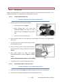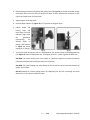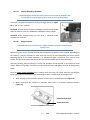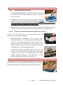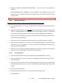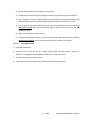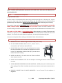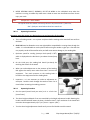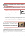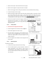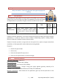
1
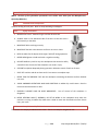
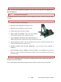
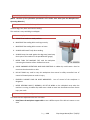
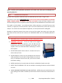
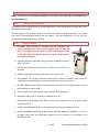
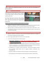
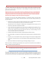
19. ROUTER, PLUNGE (Porter-Cable 6931, Porter-Cable 1001) (NOTE: Portions of the information presented in this section were taken from the Manufacturer’s Operating Manuals.) 19.1. Intended Use & Prerequisites Routers are typically used to cut grooves, hollow out larger areas and create decorative trims along the edge of a piece of wood. We have several routers in the Woodshop, but the principles of operation are generally the same for each model. 19.2. Safety Precautions a. LARGE DIAMETER BITS are for use only in a router table. Using bits over 1" diameter in a handheld router can easily cause you to lose control of the tool. b. INSPECT router bits for damage prior to use. c. NEVER touch router bits after use, as they may be extremely hot. d. MAKE all adjustments with the router power switch in the OFF position, bit stopped and router unplugged. e. NEVER start the router with the bit in contact with the stock. f. MAKE SURE that the switch is in the OFF position before plugging the unit in. g. HOLD the router securely when turning the motor on. The high starting torque will cause the router to twist when it is turned on. h. WAIT until the router spindle stops rotating before putting it down on the work surface. i. ALL BITS in the Woodshop will require three to five passes dependent upon the type and size of the bit. Lower the bit on the router in 1/8” increments prior to each pass. j. KEEP electrical cord away from the bit. k. KEEP your hands on both handles and feed the cutter at an even rate of speed. l. AT COMPLETION OF AN OPERATION: turn the machine away from you, turn it OFF, let it come to a complete stop, and place it on its side. P a g e 109 Shop Usage Manual (Rev. 7/18/12) 19.3. Setup & Use – Plunge Router 19.3.1. Selecting the Bit Routers are furnished with 1/4" and 1/2" diameter collets that will accommodate bits with 1/4" or 1/2" diameter shanks that are installed directly into the power unit collet. 19.3.2. Installing & Removing the Bit CAUTION: DISCONNECT TOOL FROM POWER SOURCE. a. Remove motor unit from base unit as follows: Loosen clamp screw (A) Figure 1. While holding base, turn motor unit COUNTERCLOCKWISE until lower pin (B) in motor housing is disengaged from groove in base. Lift motor unit free from base unit. b. Clean and insert shank of bit into collet until shank bottoms. Then back it out approximately 3/8” to 1/2“. c. Lay motor unit on its side on bench with the collet pointing AWAY from you. d. Place one wrench on flats on chuck with the opposite end of the wrench resting on the bench to your left, Figure 2. e. Place other wrench on collet and tighten COUNTERCLOCKWISE as shown in Figure 2. TIGHTEN FIRMLY. AVOID POSSIBLE DAMAGE TO COLLET. NEVER TIGHTEN COLLET WITHOUT BIT. f. To remove the bit, reverse the foregoing procedure. 19.3.3. Assembling the Motor in the Router Base CAUTION: DISCONNECT TOOL FROM POWER SOURCE. a. Loosen the clamp screw (A) Figure 1 to allow the power unit to be set in the base unit. b. Insert motor unit into base aligning lower pin (B) with groove in base. P a g e 110 Shop Usage Manual (Rev. 7/18/12) c. Rotate motor unit CLOCKWISE into base until upper guide pins are rigidly set in the groove of the base. d. Tighten clamp screw firmly. 19.3.4. Adjusting Depth of Cut CAUTION: DISCONNECT TOOL FROM POWER SOURCE. a. Loosen clamp screw (A), Figure 3. b. While holding base (E), turn motor unit (F), Figure 3, COUNTERCLOCKWISE until the tip of the bit is above bottom surface of base. c. Set router on flat wood surface. d. Turn motor unit (F), Figure 3, CLOCKWISE until bit touches the wood surface. e. Tighten clamp screw (A), Figure 3. f. Rotate depth adjusting ring (B), Figure 3, until the zero-line (C) is opposite the index line (D) on the housing. g. Loosen clamp screw (A), Figure 3. h. Tip the router so bit is clear of the wood surface. Turn motor unit (F), Figure 3 CLOCKWISE until the index line (D) on the motor housing reaches the desired depth indicated on the ring. i. Tighten clamp screw (A), Figure 3 firmly. NOTE: Setting the index line to 1/4" on the ring means the cutting edge of the bit is exposed 1/4" below the base. 19.3.5. Adjusting Sub-base Alignment Applications using a template guide require the bit to be centered within the guide. This, in turn, requires the center hole in the sub-base to be in line with the collet of the motor unit. Your model has an adjustable sub-base which has been aligned at the factory. If the sub-base has been removed and/or readjustment is required, proceed as follows: CAUTION: Be sure power switch is in “OFF” position and tool is disconnected from power source to avoid accidental starting of motor which could result in personal injury. P a g e 111 Shop Usage Manual (Rev. 7/18/12) a. Loosen sub-base mounting screws just enough to allow sub-base to move on base. b. Loosen clamp screw (see Figure 4), and adjust motor so that the collet nut engages the center hole in the sub-base. Allow the subbase to center itself on the collet nut. Tighten clamp screw. c. Tighten sub-base mounting screws securely. 19.3.6. Installing Motor in Plunge Base CAUTION: DISCONNECT TOOL FROM POWER SOURCE. a. Support clamp (see Figure 5) and loosen motor clamp screw approximately 1/2", with Allen wrench (furnished). b. Insert motor unit into base with switch positioned at front of left handle (see rear view in Figure 6), and align the four pins (A) Figure 6, in the motor case with the slots (B) Figure 6, in the base. c. Seat motor in base and tighten clamp screw to secure. 19.3.7. Removing Motor from Plunge Base CAUTION: DISCONNECT TOOL FROM POWER SOURCE a. Remove clamp screw, flat washer, lock washer, and clamp locking nut. b. Insert Allen wrench (A) Figure 7, as shown, to contact locking plate. Tap lightly to release and remove locking plate. c. Slide motor out of base. d. Reassemble clamp screw, lock washer, flat washer, locking plate and clamp locking nut to base and tighten lightly to prevent loss. P a g e 112 Shop Usage Manual (Rev. 7/18/12) 19.3.8. Installing & Removing the Bit CAUTION: Be sure power switch is in the OFF position and tool is disconnected from power source to avoid accidental starting of motor which could result in personal injury. a. Stand router upside down on its motor cap (see Figure 8). b. Clean and insert shank of bit into collet until shank bottoms. Then back it out approximately 3/8” to 1/2“. c. Place one wrench on flats on chuck and one wrench on collet nut (see Figure 8). Tighten firmly. DO NOT ALLOW WRENCHES TO CONTACT COLUMNS (A) Figure 9, AS COLUMNS MAY BE DAMAGED, RESTRICTING PLUNGE ACTION. NEVER TIGHTEN COLLET NUT WITHOUT BIT INSERTED. TO DO SO MAY DAMAGE COLLET. d. To remove bit, reverse the foregoing procedure. If bit does not remove easily, tap the collet nut with wrench to release bit. 19.3.9. Adjusting Plunge Base CAUTION: DISCONNECT TOOL FROM POWER SOURCE a. Loosen depth rod locking knob (A) Figure 10, and depth indicator knob (D) Figure 10, allowing the depth rod (E) Figure 10, to contact one of the turret stops (B) Figure 10. Normally the deepest desired cut is set with the depth rod resting on the shortest turret stop (A) Figure 11. The other two fixed stops then provide reduced cutting depths of 1/4" and 1/2" respectively. The three adjustable stops may be adjusted to any desired height. Any combination of fixed and/or adjustable stops may be utilized to achieve the desired depths required for a particular job. P a g e 113 Shop Usage Manual (Rev. 7/18/12) b. Release plunge mechanism by pulling the locking lever (B) Figure 9, to the left and lower plunge mechanism until the router bit just touches the work surface. Release lever and push to the right to lock mechanism in this position. c. Tighten depth rod locking knob. d. Position depth indicator (C) Figure 10, at “0” position and tighten knob. e. Loosen depth rod locking knob and raise depth rod until indicator aligns with the graduation representing the desired depth of plunge. (The example in Figure 12 shows setting for 1" plunge.) f. Turn lower travel limiting nut until it is approximately 1/4" above the top of the plunge housing (see Figure 13). While holding lower nut, turn upper nut until it “jambs” against the lower nut. CAUTION: The travel limiting nuts must always be “jammed” together to prevent movement (caused by vibration) which could prevent full bit retraction. CAUTION: The travel limiting nuts must always be set so that bit can be retracted into base of router, clear of work. DO NOT attempt to increase plunge travel by readjusting the stop nut. Increasing the travel beyond 2-1/2" can cause mechanism to jam. P a g e 114 Shop Usage Manual (Rev. 7/18/12) 19.3.10. Starting & Stopping the Motor CAUTION: Before starting the router make sure bit is clear of workpiece and foreign objects. Also keep firm grip on router to resist starting torque. The motor is started and stopped by setting the toggle switch (A) Figure 14 to “ON” or “OFF” position. CAUTION: To avoid personal injury or damage to finished work always allow the motor to come to a COMPLETE STOP before setting it down. CAUTION: When through-cutting, be sure there is clearance under workpiece for router bit. 19.3.11. Using the Router CAUTION: Always be sure the work is rigidly clamped or otherwise secured before making a cut. Before using your router, consider the kind and total amount of material to be removed. Depending on the material, it may be necessary to make more than one cut to avoid overloading the motor. Before beginning the cut on the actual workpiece, it is advisable to make a sample cut on a piece of scrap lumber. This will show exactly how the cut will look as well as enable you to check dimensions. Generally speaking, when working on a bench, the workpiece should be held on the bench by wood clamps. When routing edges, the router must be held firmly down and against the work by both guiding knobs. Since the cutter rotates clockwise (when viewing router from top), the router should be moved from left to right (counter-clockwise) as you stand facing the work. Always route any end grain first. When working on the inside of a template, move router in clockwise direction (Figure 15). When working on the outside of a template, move router in a counter clockwise direction (Figure 15). Route End Grain First Should Start Here Fig. 15 P a g e 115 Shop Usage Manual (Rev. 7/18/12) WARNING: Avoid “Climb-Cutting” (cutting in direction opposite that shown in Figure 15), “ClimbCutting” increases the chance for loss of control resulting in possible personal injury. When “ClimbCutting” is required (backing around a corner), exercise extreme caution to maintain control of router. The speed and depth of cut will depend largely on the type of material being worked upon. Keep the cutting pressure constant but do not crowd the router so the motor speed slows excessively. It may be necessary on exceptionally hard woods or problem materials to make more than one pass at various settings to get the desired depth of cut. When making cuts on all four edges of the workpiece, it is advisable to have the first cut on the end of the piece across the grain. Thus, if chipping of wood occurs at the end of a cut, it will be removed when making the next cut parallel with the grain. Periodically wipe columns clean with a dry cloth. DO NOT lubricate columns. 19.3.12. Edge Guide An edge guide is available as an accessory to aid in routing operations such as: straight edge planing, parallel grooving, dado or slotting operations. To assemble, insert guide rods (A) in holes in base, Figure 16, and secure with screws (B). The guide (C) is adjusted on the rods and secured in desired position with thumb screws (D). 19.3.13. Template Guides CAUTION: DISCONNECT TOOL FROM POWER SOURCE. A wide variety of template guides are available for use in pattern and template routing operations, Figure 17 shows a typical combination bit, template guide, and locknut. To install, insert template guide in center hole in router base and secure in place with the locknut. BEFORE CONNECTING ROUTER TO POWER SOURCE: Install bit, adjust depth of cut, and rotate router chuck by hand to be sure bit or collet does not contact template guide. P a g e 116 Shop Usage Manual (Rev. 7/18/12) 20. ROUTER, TABLE (Rockler JessEm Route-R-Lift Table) & (Clincher Fence Machine Table with Jointech Smartfence Plus CL-18) (NOTE: Portions of the information presented in this section were taken from the Manufacturer’s Operating Manuals.) 20.1. Intended Use & Prerequisites The router inside the Rockler JessEm Route-R-Lift Table & Fence system has a more powerful motor. Use this router for large bits to ensure you do not burn up the router motor. It has a basic movable fence. Two routers have the Clincher Fence Machine Table with Jointech Smartfence Plus CL-18 and a smaller motor, but have a precision adjustable fence system. These two routers use the same type lift table. 20.2. Safety Precautions a. MAKE all adjustments with the router power switch in the OFF position, bit stopped and router unplugged. b. INSPECT router bits for damage prior to use. c. LARGER BITS run at slower speeds and require more HP. d. NEVER touch router bits after use, as they may be extremely hot. DO NOT bottom out the bit in the collet or partially insert the bit. Instead, completely insert the bit, then back off approximately 3/8” to 1/2“ and tighten collar securely. e. NEVER start the router with the bit in contact with the stock. f. KEEP workpiece against the fence or bit collar during cutting operation. g. USE FEATHERBOARDS to support the workpiece against the router table. h. DO NOT force workpiece into router bit. i. KEEP hands and fingers 2” from bit. j. ALWAYS feed material from the right side of the bit to the left side of the bit for cutting the outside edge of a workpiece. k. ALL BITS in the Woodshop will require three to five passes dependent upon the type and size of the bit. Raise bit in 1/8” increments. l. TAKE LIGHT CUTS. Heavy cuts invite kickback. If necessary, move the fence closer to the bit or switch to a larger guide bearing. m. AVOID SHAPING SMALL STOCK: Instead, shape a larger piece and reduce it in size afterwards. If you must shape a small piece, build an appropriate jig or secure the work within the jaws of a wooden hand screw clamp. P a g e 117 Shop Usage Manual (Rev. 7/18/12) 20.3. Set-Up & Use – Router Table 20.3.1. Rockler JessEm Route-R-Lift Table ADJUSTING ROUTER/BIT HEIGHT: Use handle to raise and lower router bit to desired level. The height change per revolution is labeled on each of our routers. CHANGING BITS: Use handle to raise router enough to get the two wrenches on the shaft to loosen the collet and change bits. CAUTION: Please do not jam the router to the very top of the mechanism; this can cause the mechanism to jam and will require the Maintenance Team to repair it. Adjusting Fence: most uses of the fence are to hold the wood some small distance away from the router bit. There is a knob on the back of each end of the fence to secure the setting. 20.3.2. Clincher Fence Machine with Jointech Smartfence Plus CL-18 fence. The basic router and table work the same as the above system. The difference is in the fence, discussed below: MICRO-ADJUSTMENT THUMBWHEEL has detented Micro Adjustments every .001”. It is especially useful when making dadoes and other cuts requiring high precision fence settings. Its bidirectional scale sleeve is adjustable for zeroing. Because of the detents, you don’t even have to look at its scale to know how many thousandths of an inch you have moved the fence. 3 POSITION CLINCHER’S CAM-HANDLE makes positioning fast and accurate. In the vertical position, the carriage freely moves toward and away from your cutter. In the middle position, brass indexer engages leadscrew allowing for micro-adjustments of fence. Horizontal position locks Clincher securely into place. 20.4. Featherboards Using featherboards can be very helpful for stabilizing the wood as it enters the area of the bit. Placing a featherboard vertically can help cut consistent depth dados and grooves, and featherboards can help prevent kickbacks. P a g e 118 Shop Usage Manual (Rev. 7/18/12) 21. ROUTER, EDGE TABLE (Horizontal Router Table MLCS #9767) (NOTE: Portions of the information presented in this section were taken from the Manufacturer’s Operating Manuals.) 21.1. Intended Use & Prerequisites This router setup quickly and easily makes mortise and tenon joinery, raised panels with vertical raised panel bits, moldings and picture frames. It is much safer and more accurate than standing wide stock on edge. 21.2. Safety Precautions a. INSPECT router bits for damage prior to use. b. LARGER BITS run at slower speeds and require more HP. c. NEVER touch router bits after use, as they may be extremely hot. d. MAKE all adjustments with the router power switch in the OFF position, bit stopped and router unplugged. e. DO NOT bottom out the bit in the collet or partially insert the bit. Instead, completely insert the bit, then back off approximately 3/8” to 1/2“ and tighten collar securely. f. NEVER start the router with the bit in contact with the stock. g. KEEP workpiece against the fence or bit collar during cutting operation. h. USE FEATHERBOARDS to support the workpiece against the router table. i. DO NOT force workpiece into router bit. j. KEEP hands and fingers 2” from bit. k. ALWAYS feed material from the right side of the bit to the left side of the bit for cutting the outside edge of a workpiece. l. ALL BITS in the Woodshop will require three to five passes dependent upon the type and size of the bit. Raise bit in 1/8” increments. m. TAKE LIGHT CUTS. Heavy cuts invite kickback. If necessary, move the fence closer to the bit or switch to a larger guide bearing. n. AVOID SHAPING SMALL STOCK: Instead, shape a larger piece and reduce it in size afterwards. If you must shape a small piece, build an appropriate jig or secure the work within the jaws of a wooden hand screw clamp. P a g e 119 Shop Usage Manual (Rev. 7/18/12) 21.3. Set-Up & Use – Edge Router Table Taking several shallow passes will yield a better cut than trying to cut too aggressively which may lead to a poor cut quality or excessive tear-out. 21.3.1. Horizontal Table Specifications Micro adjustable bit height adjustments. 1/16" per turn allows for very precise adjustments: (1/4 turn = 1/64", 1/2 turn = 1/32", 3/4 turn = 3/64"). Table is 24" wide x 20" deep x 25" height with surface extension fences, on both sides of the router plate give maximum support to long stock. Router plate is held in routing position by aluminum extrusions, along with two locking knobs which safely secure the sliding router plate in position. Raise your router up to 2-3/8" above the table. 21.3.2. Adjusting Bit Height a. Loosen the two knobs that lock the router into place. b. Turn the crank on the top of the assembly to raise and lower the router to desired position. One revolution equals 1/16”. c. Tighten the two knobs that lock the router into place. 21.3.3. Adjusting Router Settings The router is a 2 horsepower Bosch 1613EVS router with variable speed and fine adjustment knob. To adjust the router or to install bits, just swing the horizontal table sideways for easy access to the router unit. P a g e 120 Shop Usage Manual (Rev. 7/18/12) 21.3.4. Changing Router Bits a. Press spindle lock to prevent rotation of collet chuck. NOTE: it may be necessary to rotate collet nut to engage spindle lock (Fig. 3). b. Next, use the collet wrench to loosen the collet chuck assembly in counter-clockwise direction (viewed from bottom of router). c. Insert the shank of the router bit into the collet chuck assembly as far as it will go, then back the shank out until the cutters are approximately 1/8" to 1/4" away from the collet nut face. d. With the router bit inserted and the spindle lock engaged, use the collet wrench to firmly tighten the collet chuck assembly in a clockwise direction (viewed from bottom of router). P a g e 121 Shop Usage Manual (Rev. 7/18/12) 21.3.5. Routing the Workpiece Normally, you feed a router opposite to rotation direction. This gives you just enough resistance to maintain control and avoid kickback. When feeding a workpiece into the spinning bit of the router, you want to choose the direction that forces the bit to push the wood back against you. This direction changes depending on whether the bit is above or below the workpiece. a. Bit BELOW workpiece: If the BIT is setup to cut BELOW the workpiece, feed from LEFT to RIGHT. Stock to be routed should move over the top of the bit using push pads to securely hold workpiece and protect your fingers. b. Bit ABOVE workpiece: If the BIT is setup to cut ABOVE the workpiece, feed from RIGHT to LEFT. Be extra careful not to run your fingers under the spinning bit – keep a safe distance between your fingers and the bit. P a g e 122 Shop Usage Manual (Rev. 7/18/12) 22. SANDER, 6” BELT/12” DISK (Powermatic Model BD31A) (NOTE: Portions of the information presented in this section were taken from the Manufacturer’s Operating Manuals.) 22.1. Intended Use & Prerequisites Used for sanding of small parts. Both are setup with 80 grit sandpaper. 22.2. Safety Precautions a. MAINTAIN at least 3” between fingers and the abrasive belt. b. ALWAYS sand on the downward side of the disc so that the work is held securely on the table. c. MAKE SURE belt is tracking correctly. d. MAKE SURE the belt or disc abrasive surface is not torn or loose. e. KEEP the table free of objects which might “walk off’ during operation. f. NEVER WEAR gloves or hold work with a rag when sanding. g. DO NOT SAND very small or very thin workpieces that cannot be safely controlled. Loss of control of the workpiece can result in injury. h. SUPPORT workpiece adequately during operation. Maintain control of work at all times. i. SHUT OFF machine and do not leave until it has come to a complete stop. j. NEVER TURN THE MACHINE “ON” with the workpiece contacting the abrasive surface. Kickback can occur. k. AVOID AWKWARD OPERATIONS AND HAND POSITIONS. A sudden slip could cause a hand to move into the abrasive disc or belt. l. PROPERLY SUPPORT LONG OR WIDE WORKPIECES. dangerous. Loss of control of the workpiece is m. NEVER PERFORM LAYOUT, ASSEMBLY, OR SET-UP WORK on the table/work area when the machine is running. A sudden slip could cause a hand to move into the abrasive surface. Severe injury can result. 22.3. Setup & Use – Belt/Disk Sander The sanders are setup by the Maintenance Team. There is no setup for the general user. P a g e 123 Shop Usage Manual (Rev. 7/18/12) 23. SANDER, 1” BELT/8” DISK (Grizzly Model H8192) (NOTE: Portions of the information presented in this section were taken from the Manufacturer’s Operating Manuals.) 23.1. Intended Use & Prerequisites The Woodshop has two of these machines. Used for sanding of small parts. Both are setup with 80 grit sandpaper. 23.2. Safety Precautions a. DO NOT use sander on metal products. b. MAKE SURE the sanding belt is tracking correctly. c. MAKE SURE the sanding belt is not torn or loose. d. ALWAYS HOLD work firmly when sanding. e. NEVER TURN THE MACHINE “ON” with the workpiece contacting the abrasive surface. Kickback can occur. f. AVOID AWKWARD OPERATIONS AND HAND POSITIONS. A sudden slip could cause a hand to move into the abrasive disc or belt. g. DO NOT SAND very small or very thin workpieces that cannot be safely controlled. Loss of control of the workpiece can result in injury. h. PROPERLY SUPPORT LONG OR WIDE WORKPIECES. dangerous. i. Loss of control of the workpiece is NEVER PERFORM LAYOUT, ASSEMBLY, OR SET-UP WORK on the table/work area when the machine is running. A sudden slip could cause a hand to move into the abrasive surface. Severe injury can result. 23.3. Setup & Use – Belt/Disk Sander Finish curves or odd-shaped work by using the oscillating spindle sander instead (see Section 29. SANDER, OSCILLATING SPINDLE). You can sand chamfers and bevels by tilting the aluminum tables on either the belt or disk sander. P a g e 124 Shop Usage Manual (Rev. 7/18/12) 24. SANDER, BELT (3x21” Craftsman 315.117131, Porter-Cable 352VS) (NOTE: Portions of the information presented in this section were taken from the Manufacturer’s Operating Manuals.) 24.1. Intended Use & Prerequisites The Belt Sander is useful for sanding the surface and edges of pieces of wood that are too large to be sanded on the disc sander. The Belt Sander can be used on flat or curved pieces. 24.2. Safety Precautions a. ALWAYS UNPLUG before changing abrasive belts. b. SANDING OF LEAD-BASED PAINT IS NOT ALLOWED. c. ADJUST TRACKING of the abrasive belt prior to sanding operation. d. PRIMARY SAFETY HAZARD: Workers may catch their hands, clothing, or jewelry in the in-running rolls. Also, contact with an abrasive surface can cause abrasions and lacerations. e. ALWAYS sand on the downward-moving side of the disk or belt. f. WOOD splinters and chips may be thrown from the sanding action. g. REPLACE torn, frayed, or excessively worn belts. A worn-out belt can cause massive heat buildup, which can cause it to tear or break and pelt the surrounding area with projected bits. 24.3. Setup & Use – Belt Sander a. Make sure the dust collection bag is securely attached before sanding, AND make sure the dust collection valve is open to allow dust particles to be blown into the dust collection bag. After long periods of sanding, or when first using the tool, check to see if the dust collection bag needs to be emptied. b. Start the sander above the material, then lower the sander so the back end makes contact first. Move the sander back and forth in a straight line for best results. c. Work through the “grits". This is the process of sanding a workpiece by using progressively finer pieces of sandpaper to get a smooth finish. Each progressive piece of sandpaper removes the scratches from the previous sanding. Skipping grits to save time is not necessarily a good idea. You will often end up sanding longer just to remove the scratches left by the previous grit. This is more important with harder woods like maple than it is with softer woods like pine. d. For better-looking results, always sand with the grain of the wood, especially with coarse sandpaper. P a g e 125 Shop Usage Manual (Rev. 7/18/12) 25. SANDER, EDGE (6” BELT KUFO Model SK-3000SD) (NOTE: Portions of the information presented in this section were taken from the Manufacturer’s Operating Manuals.) 25.1. Intended Use & Prerequisites Used for edge, face, bevel and contour sanding. This machine is setup with 80 grit sandpaper. 25.2. a. Safety Precautions DO NOT use sander on metal products. b. MAKE SURE the sanding belt is tracking correctly. c. MAKE SURE the sanding belt is not torn or loose. d. ALWAYS HOLD work firmly when sanding. e. ALWAYS brace the wood against the edge stop (metal stop that is part of the machine or the provided miter gauge). f. NEVER TURN THE MACHINE “ON” with the workpiece contacting the abrasive surface. Kickback can occur. g. AVOID AWKWARD OPERATIONS AND HAND POSITIONS. A sudden slip could cause a hand to move into the abrasive disc or belt. h. DO NOT SAND very small or very thin workpieces that cannot be safely controlled. Loss of control of the workpiece can result in injury. i. PROPERLY SUPPORT LONG OR WIDE WORKPIECES. dangerous. j. NEVER PERFORM LAYOUT, ASSEMBLY, OR SET-UP WORK on the table/work area when the machine is running. A sudden slip could cause a hand to move into the abrasive surface. Severe injury can result. 25.3. Loss of control of the workpiece is Setup & Use – Edge Sander The sander has two adjustments the user can make: Raise/lower the workpiece support table to use a different part of the belt as it wears on one area. P a g e 126 Shop Usage Manual (Rev. 7/18/12) o There are two knobs under the support table which you loosen, being sure to support the table with one hand, adjust the table, and then retighten the two knobs. Tilt the entire belt assembly from its nominal 90 degree configuration to 0 degrees or horizontal position. o When facing the machine, below the belt level and on the right hand side is a single knob and a scale marked from 0 to 90 degrees. Securely hold the belt mechanism while loosening the knob, adjust to the desired angle and retighten the knob. o Please return the machine to the upright 90 degree position when finished sanding. P a g e 127 Shop Usage Manual (Rev. 7/18/12) 26. SANDER, RANDOM ORBIT PALM – PNEUMATIC (Campbell Hausfeld PL1565) (NOTE: Portions of the information presented in this section were taken from the Manufacturer’s Operating Manuals.) 26.1. Intended Use & Prerequisites Used for finish sanding of projects. 5” Sandpaper is provided by the Woodworkers Club for a nominal fee and is located in one of the cabinets, or you may buy and bring in your own supply. 26.2. Safety Precautions a. UNHOOK air hose before changing abrasive sandpaper. b. VERIFY air pressure is set between 60-65 PSI. The use of excessive PSI will damage equipment and is a safety hazard to the operator and others in the immediate area. 26.3. Setup & Use – Pneumatic Air/Oil The blue device in this picture regulates the air pressure and it needs to be checked to make sure the pressure is set between 60-65 PSI before connecting the tool. The picture shows the pressurized air system located by one of the sanding tables. CAUTION: The use of excessive PSI will damage the equipment and is a safety hazard to the operator and others in the immediate area. 26.4. Setup & Use – Random Orbit Palm Sander Sandpaper for these machines comes with adhesive backing. The old sandpaper can be easily peeled off, being sure to disconnect the air hose first. When installing the new paper, you should center the pad on the paper and press against the table. Sanding is best done on top of the sanding table, with the table air system turned on (the switch for this is on the side of the sanding table). Let the sander to the work. It operates best if you guide the sander around your wood with very light pressure. Heavy pressure on the sander will wear out the sandpaper AND the pad faster, and will result in uneven sanding and premature replacement of the pad. For best results, inspect and replace the abrasive sandpaper often for wear or damage. P a g e 128 Speed of sander is controlled by a switch under the hose inlet area Shop Usage Manual (Rev. 7/18/12) 27. SANDER, 36” WIDE BELT (Timesavers S311-13-1T) (NOTE: Portions of the information presented in this section were taken from the Manufacturer’s Operating Manuals.) 27.1. Intended Use & Prerequisites The dual roller, single drum wide belt sander can sand wood up to 36” wide. The grit is 100. The sander is to be used on HARDWOODS only. Do not use the sander on PINE, SPRUCE, FIR, PAINTED WOOD, TREATED WOOD, PLYWOOD or any other soft wood as these will leave material on the abrasive sanding belt and may negatively impact the project the next Woodworkers Club member sands. This sander is a Finish Sander – not a thickness planer. When operators try to take off way too much material in a single pass, too much pressure is put on the stock material which causes the unit to stall and quit. This causes harm to the expensive equipment, its conveyor belt and 36" sanding belt. Members are required to attend a short class on the use of the sander. One cannot use it unless they have taken the class and have their name on the “APPROVED USERS” list at the Woodshop Monitor’s desk. 27.2. Safety Precautions a. MAINTAIN at least 3” between fingers and the in-feed point of entry. b. EMERGENCY STOP BAR – If the unit needs to be stopped IMMEDIATELY during any operation, press the RED stop bar located across the front of the equipment at the infeed. Once stopped, lower the infeed table before attempting to remove the workpiece. c. DO NOT SAND material shorter than 12”, narrower than 3/4” or thinner than 1/8” thick. d. DO NOT SAND very small or very thin workpieces that cannot be safely controlled. Loss of control of the workpiece can result in injury. If a workpiece is thinner than 1/8”, you must use a backer board when sanding. e. NEVER stand directly in line with either the infeed or outfeed sides. Stand to one side. f. NEVER TURN THE MACHINE “ON” with the workpiece contacting the abrasive surface. Kickback can occur. g. AVOID AWKWARD OPERATIONS AND HAND POSITIONS – NEVER place your hands directly at the front opening of the infeed. A sudden slip could cause a hand to move into the abrasive disc or belt. P a g e 129 Shop Usage Manual (Rev. 7/18/12) h. PROPERLY SUPPORT LONG OR WIDE WORKPIECES. dangerous. i. Loss of control of the workpiece is NEVER PERFORM LAYOUT, ASSEMBLY, OR SET-UP WORK on the table/work area when the machine is running. A sudden slip could cause a hand to move into the abrasive surface. Severe injury can result. 27.3. Setup & Use – Wide Belt Sander 27.3.1. Operating Precautions Operators must take proper care during the set-up and operation of the sander: a. This is a finishing sander – use a jointer and planer before sanding so the wood will have uniform thickness. b. GLUE-UPS must be allowed to cure overnight AND be scraped before running them through the sander. It is also advisable to use the planer before using the sander on glue-ups. Glue that has not properly cured will be transferred to, and will cause severe damage to, the sanding belt. c. Optimum speed for sanding (conveyor belt speed) is 50%, which is displayed on the dial that is just below the start/stop buttons. d. On the initial pass, the sanding belt should just barely be touching the surface of the wood. e. When you make adjustments to the pressure of the Sanding Belt against the wood, never make more than ¼ turn on the equipment. Too much pressure on the sanding belts is harmful to the equipment and the Sanding Belts. f. Important – It is not necessary to make an adjustment on each pass. Send the stock through the sander at least 3 to 4 times before increasing the sanding pressure. 27.3.2. Turn-On Procedure a. Unlock the safety disconnect box, and turn power ON. (See Woodshop Monitor for key) b. Open side access panel – Activate air pressure on Sanding Belt by pulling down on blue collar – Close access panel. c. Place wood piece with spacer on top of in-feed table under the Red Bar. Use the Depth Wheel below side access panel to raise or lower in-feed table until spacer makes slight contact with Red Bar. d. Remove spacer and workpiece. e. Press the Red STOP button to reset – Press the Green START button to start. j. Insert workpiece: P a g e 130 Shop Usage Manual (Rev. 7/18/12) 1) Always feed the wood so the sanding is with the grain. 2) Do Not Force-Feed the workpiece through the machine, let sander apply proper feed rate. 3) You can adjust the conveyor feed speed on the sander with the round dial located to the lower left side of the front. Set dial at approximately the 45 minute position on a clock. 4) If you cannot hear the belt sanding the wood, turn the Depth Wheel counter-clockwise no more than 1/4 turn and insert the workpiece again. Repeat until you can hear the belt sanding the wood. 5) Make at total of 4 passes at this setting. 6) If the desired sanding results are not yet achieved, turn the Depth Wheel counter-clockwise no more than 1/4 turn and insert workpiece for a total of 4 passes at this setting. 27.3.3. Turn-Off Procedure a. Press Red STOP button. b. After you can hear that the belt is no longer turning, open side access panel – Release air pressure on sanding belt by pulling down on blue collar – Close access panel. c. Turn Main Power Switch to OFF and lock. d. Clean/vacuum any residual dust from the equipment and surrounding area. P a g e 131 Shop Usage Manual (Rev. 7/18/12) 28. SANDER, DRUM (Jet 16-32 Plus) (NOTE: Portions of the information presented in this section were taken from the Manufacturer’s Operating Manuals.) 28.1. Intended Use & Prerequisites The grit of the belt is 100. Jet drum sander is locked because belts were being messed up with glue at an alarming rate. Anyone can use it - there is not a list. The monitor has the key and will ask the person if the wood has been glued that day or the day before. Glue has to have dried overnight before they will give you the key. The sander is to be used on HARDWOODS only. Do not use the sander on PINE, SPRUCE, FIR, PAINTED WOOD, TREATED WOOD, PLYWOOD or any other soft wood as these will leave material on the abrasive sanding belt and may negatively impact the project the next Woodworkers Club member sands. This sander is a Finish Sander – not a thickness planer. When operators try to take off way too much material in a single pass, too much pressure is put on the stock material which causes the unit to stall and quit. This causes harm to the expensive equipment, its conveyor belt, and sanding belt. Use a jointer and planer before sanding so the wood will have uniform thickness. 28.2. Safety Precautions a. MAINTAIN at least 3” between fingers and the in-feed point of entry. b. DO NOT SAND MATERIAL thicker than 6”, shorter than 6”, narrower than 3/4” or thinner than 1/8” thick. c. DO NOT SAND very small or very thin workpieces that cannot be safely controlled. Loss of control of the workpiece can result in injury. If a workpiece is thinner than 1/8”, you must use a backer board when sanding. d. NEVER stand directly in line with either the infeed or outfeed sides. Stand to one side. e. NEVER TURN THE MACHINE “ON” with the workpiece contacting the abrasive surface. Kickback can occur. f. AVOID AWKWARD OPERATIONS AND HAND POSITIONS – NEVER place your hands directly at the front opening of the infeed. A sudden slip could cause a hand to move into the abrasive disc or belt. g. PROPERLY SUPPORT LONG OR WIDE WORKPIECES. dangerous. P a g e 132 Loss of control of the workpiece is Shop Usage Manual (Rev. 7/18/12) h. NEVER PERFORM LAYOUT, ASSEMBLY, OR SET-UP WORK on the table/work area when the machine is running. A sudden slip could cause a hand to move into the abrasive surface. Severe injury can result. 28.3. Setup & Use – Drum Sander TIP: lift the lid on this sander and note if there are any burn marks. If there are, don’t feed your wood where those burn marks are. 28.3.1. Operating Precautions Operators must take proper care during the set-up and operation of the sander: a. This is a finishing sander – use a jointer and planer before sanding so the wood will have uniform thickness. b. GLUE-UPS must be allowed to cure overnight AND be scraped before running them through the sander. It is also advisable to use the planer before using the sander on glue-ups. Glue that has not properly cured will be transferred to, and will cause severe damage to, the sanding belt. c. Optimum speed for sanding (conveyor belt speed) is 50%, which is displayed on the dial that is just above the start/stop lever. d. On the initial pass, the sanding belt should just barely be touching the surface of the wood. e. When you make adjustments to the pressure of the Sanding Belt against the wood, never make more than ¼ turn on the equipment. Too much pressure on the sanding belts is harmful to the equipment and the Sanding Belts. f. Important – It is not necessary to make an adjustment on each pass. Send the stock through the sander at least 3 to 4 times before increasing the sanding pressure. 28.3.2. Operating Procedure a. Set the speed (round knob you twist) to 4 or a little less [never faster]. b. The drum height and depth of cut are controlled by the height adjustment handle. Rotating the handle counterclockwise lowers the drum, clockwise raises it. One revolution of the handle will move the drum approximately 1/16” (or 1/4 turn = approx. 1/64”) c. Turn the drum height adjustment handle until you can feel the belt touch the wood. P a g e 133 Shop Usage Manual (Rev. 7/18/12) d. Turn the sander on (flip switch to towards the wall). e. Start with your piece on the side away from the motor housing, and then move it towards the housing and sand again. Depending on the width of your wood, you can do this several times before you lower the drum. Avoid feeding the wood where there are burn marks on the sanding belt. f. Start your wood through and lower the drum until you hear it sand the wood. g. Send the wood through 4 times at this setting. h. If you need more sanding, lower the drum 1/8th to 1/4th turn (1/8th turn if the wood is over 2” wide, 1/4th turn if the wood is less than 2” wide) and start the wood again. i. Circuit Breaker: The sander is equipped with a motor protective device (circuit breaker). The breaker will automatically shut the sander off when excessive current is consumed. If the breaker is tripped, turn the sander off and press the circuit breaker button on the motor to re-set. P a g e 134 Shop Usage Manual (Rev. 7/18/12) 29. SANDER, OSCILLATING SPINDLE (Jet JOVS-10) (NOTE: Portions of the information presented in this section were taken from the Manufacturer’s Operating Manuals.) 29.1. Intended Use & Prerequisites The primary use of a spindle sander is to sand inside radii. To sand flat surfaces or outside radii, use a belt sander or a disc sander. The Woodshop has two of these machines, but each has a different spindle mechanism. The spindle sets are NOT interchangeable between the two sanders. For easy identification, one set has been painted read and the other set is not painted. 29.2. Safety Precautions a. CAUTION: When sanding an enclosed area (any workpiece that requires dropping over the top of the spindle), stop the machine, place the workpiece over the spindle, and hold the workpiece firmly on the table while restarting the machine. Stop the machine before removing the workpiece. b. SUPPORT workpiece adequately during operation. MAINTAIN control of work at all times. c. DO NOT force machine. Allow machine to do the work for which it is designed. d. REMOVE adjusting keys and wrenches before turning on sander. e. THIS SANDER is for sanding curved workpieces and the interior of wooden rings. Choose the sanding drum and matching insert that best matches the size of the workpiece. f. BE VERY CAREFUL when sanding small workpieces as the force of the spinning drum may pull the workpiece from your hands. g. KEEP the table free of objects which might “walk off” during operation. h. MAKE SURE table insert, if required, is installed prior to use. i. NEVER TURN THE MACHINE “ON” before clearing the table/work area of all objects (tools, scraps of wood, etc.). j. NEVER TURN THE MACHINE “ON” with the workpiece contacting the abrasive surface. k. NOTIFY WOODSHOP MONITOR WHEN SLEEVES BECOME WORN OR DAMAGED. A torn or damaged sleeve could be unexpectedly expelled from the machine if not replaced by the Maintenance Team. P a g e 135 Shop Usage Manual (Rev. 7/18/12) l. PROPERLY SECURE SANDING DRUM on spindle before operating. m. HOLD WORKPIECE FIRMLY ON THE SANDER TABLE. To prevent loss of control, use a solid grip. n. INSPECT MATERIALS FOR DEFECTS. Loose knots and splinters can be thrown from the machine with great force. Make sure defective materials are not used on this spindle sander. o. FOREIGN OBJECTS SUCH AS NAILS AND STAPLES must be removed before sanding. p. AVOID AWKWARD OPERATIONS AND HAND POSITIONS. A sudden slip could cause a hand to contact the abrasive sleeve. q. ALWAYS FEED WORKPIECE AGAINST the direction of the sanding belt rotation. 29.3. Setup & Use – Oscillating Spindle Sander NEVER PERFORM LAYOUT, ASSEMBLY, OR SETUP WORK on the table/work area when the machine is running. A sudden slip could cause a hand to move into the abrasive surface. 29.3.1. General Usage Steps This sander is to be used with WOOD and WOOD ONLY. a. Move workpiece into machine rotation (counterclockwise) for best workpiece control. b. Keep the workpiece in contact with the sander and moving at all times. c. Hold the workpiece firmly on the table at all times. d. Select a spindle that matches the workpiece. In general, the largest diameter spindle that fits your workpiece is the best selection. e. Always use a table insert ring appropriate for the spindle being used. f. CAUTION: When sanding an enclosed area (any workpiece that requires dropping over the top of the spindle), stop the machine, place the workpiece over the spindle, and hold the workpiece firmly on the table while restarting the machine. Stop the machine before removing the workpiece. g. Use the rubber eraser provided by the Woodshop to remove sanding debris from the sandpaper during sanding operations. This will preserve the sandpaper’s efficiency. 29.3.2. Changing Spindles – Mechanical Overview The spindle arbor base consists of three sections, the hex nut at the top of the base, a tapered midsection, and a threaded bottom. The arbor nut is used to tighten or loosen the arbor, the taper is used P a g e 136 Shop Usage Manual (Rev. 7/18/12) to accurately and consistently position the arbor, and the thread is for the purpose of securing the arbor in place. The spindle arbor seats into the main drive shaft and that drive shaft is secured in position by two nuts, referred to as jam nuts. 29.3.3. Removing a Spindle a. Select a wrench end with a hole near the throat and lock onto the arbor nut. Using the opposite end of another wrench, lock onto the top jam nut. Turn the arbor nut counterclockwise while holding the top jam nut in place until the arbor turns freely. b. Remove the arbor by hand and place in the storage rack of the same machine that the arbor was removed from. 29.3.4. Inserting a Spindle a. Select a spindle for replacement from the same machine’s storage rack. (NOTE: Spindles are not interchangeable between machines) b. Examine the taper on the arbor base and the drive shaft for cleanliness. c. If either requires cleaning, wipe both with a paper towel and lubricate with one drop of antiseize lubricant on the arbor taper. d. Hand-tighten the clean spindle into the drive shaft until no discernible wobble can be felt. e. If the arbor cannot be sufficiently tightened by hand, select a wrench end with a hole near the throat and lock onto the arbor nut. Using the opposite end of another wrench, lock onto the bottom jam nut. Turn the arbor nut clockwise while holding the bottom jam nut in place until the arbor no longer wobbles. f. Do not over tighten spindles. The natural rotation of the machine and the resistance created from sanding creates a self-tightening condition. g. Select a table insert ring appropriate for the spindle being used. 29.3.5. Changing Sander Table Angle a. Loosen the lock knobs on the trunnions on each side of the under table. b. Position the table to the desired angle. c. Retighten the lock knobs. d. ALWAYS return the table to the 90 degree stop when finished. 29.3.6. Replacing Worn Sanding Drums This is a maintenance issue and may only be done by the Maintenance Team. If sanding drums need to be changed, bring the issue to the attention of the Woodshop Monitor. P a g e 137 Shop Usage Manual (Rev. 7/18/12) 30. SHAPER (Seco SK-28SP) (NOTE: Portions of the information presented in this section were taken from the Manufacturer’s Operating Manuals.) 30.1. Intended Use & Prerequisites Shapers are built stronger and heavier to swing a larger cutter than any router will handle. A shaper is used for running straight molding, raising panels, pattern cutting, and doing radius work. The shaper should only be used on a fully prepared board. This means the board has been jointed, planed and all edges are flat and there are no rough surfaces being jointed. PRIOR TO USING SHAPER, WOODSHOP MONITOR MUST BE NOTIFIED. Members are required to complete the Woodworkers Club training course on using this shaper before they are allowed to use it. The must also obtain the key from the monitor. When the shaper is unlocked, the table saw nearest the shaper must be taken off line. This is accomplished by locking the safety disconnect box on the table saw with the lock that was removed from the shaper. 30.2. Safety Precautions a. Always turn power OFF and wait until cutter bit stops turning before adjusting or changing setups and when changing cutter rotation direction. b. Select straight-grained, defect-free material for use on the shaper. c. Use one of the following methods to hold workpiece: When starting a freehand cut, YOU MUST HOLD THE WORKPIECE AGAINST THE STARTER PIN and then feed it into the cutter. NO other types of freehand cuts are allowed. If workpiece is shorter than 12”, always have the workpiece moved through the machine by a fixture or sled of some sort. User must never attempt to use hands to hold the wood being worked. The Woodshop has several different fixtures for this purpose. If workpiece is 12” or longer, you may use the fence. Hold work firmly against the fence with appropriate holding devices such as magnetic holdovers, appropriate sleds, featherboard, etc. Whenever possible, use hold-downs to keep the workpiece in position during cutting. When shaping the ends of workpieces, make sure the ends are held in a sled or fixture. P a g e 138 Shop Usage Manual (Rev. 7/18/12) d. Use only operations and workpieces which permit the operator’s hands to remain at least 8” from the cutter head. e. DIRECTION OF FEEDING WORK: FEED THE WORKPIECE into cutter rotation direction or workpiece will shoot out like a missile. Should you reverse the cutter, the feed direction will also be from the opposite direction. f. DO NOT ATTEMPT TO REVERSE YOUR DIRECTION ONCE CUTTING OPERATION HAS BEGUN. CHANGING DIRECTION CAN RESULT IN INJURY, THROWN MATERIAL, OR JAMMING OF THE CUTTER HEAD. g. MAKE SURE the cutters are sharp. h. Bottom of shaper cutter must be set in alignment as is proper for that cutter. When changing the cutter and after installation, the Woodshop Monitor, or a knowledgeable member of the Woodworkers Club, must be called to check out the installation. i. Shaper Speed is set at 9000 RPM. Do not attempt to make a change to rotation speed. j. USE proper Eye Protection and a Dust Mask. k. DO NOT WEAR TIE, GLOVES, or loose clothing. REMOVE WATCH, RINGS, and other jewelry. ROLL UP SLEEVES. l. NEVER TURN THE MACHINE “ON” before clearing the table of all objects (tools, scraps of wood, etc.). m. AVOID AWKWARD OPERATIONS AND HAND POSITIONS where a sudden slip could cause a hand to move into the cutter. n. NEVER START THE MACHINE with the workpiece contacting the cutter. o. DO NOT FEED A WORKPIECE that is warped, contains loose knots, or is embedded with foreign objects (nails, staples, etc.). Workpiece must be flat and square, with reference surface marked in cases where two ends are intended to be cut. p. PROVIDE SUFFICIENT BEARING SURFACE when shaping with a starting pin and collar(s). q. ONLY SHAPE LARGE WORKPIECES when using starting pin and collar(s). DO NOT SHAPE short or light workpieces when using starting pin and collar(s). r. POSITION THE CUTTER below the collar(s) when shaping with starting pin and collar(s). s. PROPERLY SUPPORT LONG OR WIDE WORKPIECES. t. NEVER PERFORM LAYOUT, ASSEMBLY or setup work on the table/work area when the machine is running. P a g e 139 Shop Usage Manual (Rev. 7/18/12) 30.3. Setup & Use – Shaper, General Information The shaper is pretty much just a large router, with more power, and the ability to handle much larger cutters, such as those used for raised panels or crown moldings. The variety of cutters is also much greater than those for routers. Shapers are able to run in reverse, which is necessary in performing some cuts. It is very important to always check the position of the directional switch. Feeding a board into a shaper that is turning the wrong direction could result in the board leaving the machine like a missile. It could be FATAL if the board were to hit somebody or could result in operator loosing fingers. The shaper, like some of the other Woodshop equipment, is a dangerous machine, but with proper precautions and careful set-up it doesn't need to be feared. There are several safety precautions you can, and should, use. Bearings can be used to support and align the workpiece and are installed above or below the cutter. This alone would stop many of the injuries attributed to the shaper. Jigs and fixtures are also a big help in reducing injury, and generally result in better cuts. The time spent to make them is well worth the effort. A very small device, but important one is the starter pin supplied with the machines. This is simply a metal rod, threaded on one end which screws into a hole located a few inches away from the cutter. Holding the work piece against the starter pin, and then feeding it into the cutter is the proper way to start a freehand cut. Instead of trying to shape narrow pieces, shape wide pieces and then rip them. Use a miter gauge, on end grain with a backer board to prevent tearout as the board leaves the cutter. On panels, such as raised panels for doors, shape the end grain first and then the edges parallel to the grain. This way any tear out on the end grain will be shaped off when you shape the edges. Make several shallow cuts instead of trying to make large moldings in one pass. With some caution, careful planning, and common sense, injuries from this machine can be avoided. As always, if it doesn't seem safe, DON'T DO IT. 30.4. Setup & Use – Shaper, Making Finger Joints The shaper setup is a precision operation requiring precision squares and various jigs. The setup is different for each type of cut you are interested in performing. The variations are too voluminous to be spelled out here. This section provides a detailed procedure for doing finger joint cuts on the ends of two short boards. This operation allows using boards over 18” to be joined together to P a g e 140 Shop Usage Manual (Rev. 7/18/12) make longer boards, up to a length that you have a clamp available to use for gluing. The principles described here can be adapted to do any sort of cut you need to do. If these instructions are not clear to you, consult one of the other members on the ‘Approved User’ list for the shaper. In order to get a good fit and strong joint, it is critical that this procedure is followed exactly. Also, since these boards need to be perfectly square, etc., you must check each machine you use for squareness, especially the fence on the jointer and the rip sled of the table saw. They are seldom set properly. 30.4.1. Prepare Your Wood a. Prepare your wood by selecting pieces a minimum of 18” long. This is necessary to be able to clamp them properly on the shaper. If you need shorter boards, you can finger joint both ends of an 18” board, then cut them to length before gluing. b. In order to prepare the wood, first flatten one side on the jointer. Then plane the second side (you really only need the bottom side to be flattened). Next, joint one edge on the jointer and mark clearly on the jointed edge and flattened bottom, with the mark “ref”. For a more detailed explanation, see Section 4.2 How to Prepare a Board. c. Now, rip the second edge on the table saw, then cut it to length keeping it very square. d. Using the precision square in the first cabinet above the miter saw, check your piece for square edges and ends. 30.4.2. Cutter Installation a. Be sure the shaper is not plugged in. b. Find the finger joint cutter in the “shaper cutters” drawer in the tool room. c. Bring over the sled from the tool room. Put on rods on the front of the shaper having the clamp on the right side. Clamp a workpiece under the clamp. d. Raise the cutter spindle all the way to the top. e. On the right side of the shaper, push the orange handle in to lock the cutter spindle. This often takes some time and several attempts if the cutters are in a low position. Get the dedicated double ended wrench from the drawer marked “Shaper Stuff”. Put the smaller wrench end on the top nut. Turn it clockwise to take it off. (it is a LEFT HAND thread). Next put the larger wrench end on the lower nut. Turn it counter clockwise to take it off (it is a normal, RIGHT HAND thread). f. Place an appropriate spacer or collar (if needed) at the base of the spindle for support. g. Place the cutter on the spindle. Make sure the rotation is correct for your application and being sure that the bottom of your workpiece is below the lowest cutter finger when the workpiece is against the fence. h. Place the spindle washer on top of the spacers/cutter and thread on the locknut. P a g e 141 Shop Usage Manual (Rev. 7/18/12) i. Tighten the nuts while holding the spindle stationary. j. Now, pull out the orange handle. 30.4.3. Setting up the Fence Now take the precision square and be sure the aluminum fence is square with the slot in the shaper table. Use the setup jig tied to the vacuum to do this. The setup jig fits in the table slot to make accurate squareness possible. If it is not square, remove the clamp on the sled and open the small clamp handle, square up the sled, check again and retighten solidly. Lastly, recheck again to be sure the sled is square. 30.4.4. Setting the Depth of Cut Bring over a steel straight edge. Bring a finger to the front, then put the straight edge in the bottom of a finger after first putting a piece of masking tape on the edge of the straightedge. Set the fence so that it is about 1/16 in back of the straightedge, parallel to the edge of the work piece, on both sections of the fence. It is important that the two halves of the fence are: aligned to each other, parallel to the slot in the table and a minimum of 1/32 beyond where the finger will cut. Now lock up depth control and turn on/off switch to “on”. 30.4.5. Setting up the Sled Put your workpiece on the sled (two “ref” surfaces down and against the fence back). Insert chip breaker against fence and apply squeeze clamp to ensure the chip breaker is held tight. Move the sled to the right so you can feel the tightness of chip breaker and be sure it is tight. After first loosening clamp on its post so it can be raised, push your wood to the fence (not hard to the fence). Lower clamp down, tighten it on its post and be sure when you pull back on the clamp lock, it pulls hard. Lastly, check to be sure you can rotate the cutter by hand. If not, retract the orange handle and try again. 30.4.6. Put the setup gage on the sled. Then, raise the cutter until you can fit the gage perfectly into the fingers on the cutter, then lock the wheel that raises and lowers the cutter. Be sure it is locked hard. 30.4.7. Setting Cutter Height Making the Cuts Turn on the machine and make all of your cuts only on one end of the board. Be sure your fingers are a full depth of 7/16”. If not, your setup wasn’t such as to allow a full depth cut. Reset fence, P a g e 142 Shop Usage Manual (Rev. 7/18/12) cut off fingers and try again. Put the precision square on your piece to be sure the fingers are perfectly square to the “ref” edges. Also, check it with the bottom of one female finger. If edge is not square, the fence locks are not holding. After cutting this pattern on all work pieces, use second side of setup jig to set cutter to do the other end. Raise or lower cutter to fit perfectly into the setup jig. Use uncut end of chip breaker. Put the wood in the jig, referenced properly, and cut the second (uncut) end with fingers. Check the fit between the two pieces. See that the finger fits are right, lining up perfectly on the “ref” faces. Now make all your other boards and you are finished. 30.4.8. Finishing Up To finish up, return “setup jig” to hanging near the blowpipe, raise spindle up and engage the orange spindle lock handle to lock the spindle. Use the crescent wrench to remove the top nut by turning it clockwise. Next, remove the lower nut by turning it counter clockwise. Remove cutter and put away, replace all spacers and nuts (finger tight) and cleanup. Remove sled and put in tool room on the floor. P a g e 143 Shop Usage Manual (Rev. 7/18/12) 31. STAPLER – PNEUMATIC (Grizzly Model G6042, Porter-Cable NS150A ) (NOTE: Portions of the information presented in this section were taken from the Manufacturer’s Operating Manuals.) 31.1. Intended Use & Prerequisites The stapler is designed to install 1/4 crown staples of various lengths from 5/16” to 1” (8 to 25 mm) long. This stapler is used to fasten thin workpieces. 31.2. Safety Precautions a. CAUTION: Keep tool pointed away from yourself and others at all times. b. Disconnect the tool from air supply before clearing jams, performing repairs, and during non-operations. c. Do not keep the trigger pulled on safety yoke mechanism when carrying or holding the tool. d. Never carry the tool by the hose or pull the hose to move the tool. e. Operating this stapler can propel objects into the air, causing immediate eye damage. To protect yourself, you should wear safety glasses or goggles when operating this equipment. f. This stapler discharges at 85-90 decibels. To protect your hearing, you should wear ear protection when operating this stapler. 31.3. Setup & Use – Pneumatic Air/Oil The blue device in this picture regulates the air pressure and it needs to be checked to make sure the pressure is set between 60-65 PSI before connecting the tool. There are several such setups in the Woodshop. The picture shows the pressurized air system located by the sanding table. 31.4. Setup & Use – Stapler 31.4.1. Safety Yoke Mechanism A safety yoke mechanism (bump fire) on the nose of the stapler acts as a secondary safety device. When the trigger is pressed, the stapler will not fire until the safety yoke mechanism is depressed. Before you use your stapler for the first time, check the safety yoke mechanism to ensure proper function. To do this: P a g e 144 Shop Usage Manual (Rev. 7/18/12) a. Make sure the stapler is disconnected from the air supply! b. Make sure the magazine is empty and contains no staples. c. Make sure the trigger and the safety yoke mechanism move up and down without sticking. d. Connect the stapler to the air supply. e. Without pressing the trigger, depress the safety yoke mechanism against a scrap piece of wood that is clean and free of any knots, staples, or other foreign objects. If the stapler does not fire, then the safety yoke mechanism is working correctly. If the stapler does fire when you do this, immediately disconnect the stapler from the air supply and notify the Woodshop Monitor. f. Similarly if the stapler fires when the trigger is pulled, without the safety yoke mechanism being depressed, then the stapler is not working properly. If the stapler does fire, immediately disconnect the stapler from the air supply and notify the Woodshop Monitor. 31.4.2. Loading Stapler a. Disconnect the air supply from the stapler! b. Push the magazine latch in direction shown in Figure 1. c. Pull back the magazine cover until it stops. d. Point the stapler up and insert a stick of staples into the magazine as shown in Figure 2. Make sure that the pointed ends of the staples point in the same direction as the stapler nose piece. e. Push the magazine cover forward until the magazine latch locks in place. 31.4.3. Operating Stapler To operate your stapler: a. Connect the air supply to the quick connect fitting. b. Test the loaded stapler for proper penetration. Hold the stapler perpendicular to the surface of a piece of clean scrap wood that is thick enough for the length of staples you have loaded. Depress the safety yoke mechanism on your workpiece. P a g e 145 Shop Usage Manual (Rev. 7/18/12) c. Before pressing the trigger, make sure your free hand is positioned out of the way of a potential path of a staple in case of deflection. (Deflection is caused when the staple changes its path, resulting in the staple puncturing the surface of the workpiece as shown in Figure 3.) Besides damaging your workpiece, deflection can cause injury if your free hand is securing the workpiece in the location that the staple deflects. d. Press the trigger. If the staple drove into the wood far enough, continue with your intended operations. If the staple either went too far or not far enough, then adjust the air pressure. More air pressure will make the staple go deeper and less air pressure will decrease the staple penetration. 31.4.4. Clearing Jammed Staples The most frequent situation with any type of stapler is a staple jam. A jammed staple must be cleared before using the stapler again. The two places where a staple can get jammed are the magazine and the discharge area. To clear a jammed staple from the magazine: a. Disconnect the stapler from the air supply! b. Open the magazine cover and pull the magazine all the way back. c. Locate and remove the jammed staple with a pair of needle nose pliers. Close the magazine cover so it latches. To clear a jammed staple from the discharge area: a. Disconnect the stapler from the air supply! b. Remove all of the staples from the magazine. c. The jammed staple should now be visible; remove it from the discharge area with needle nose pliers. d. Replace the staples. Push the magazine closed and snap the quick release latch back into operating position. P a g e 146 Shop Usage Manual (Rev. 7/18/12) 32. Gluing Always remember to clean up the glue bottle & any glue droppings with a wet rag. 32.1. Glue Information The Woodworkers Club supplies one type of glue for all members to use. There is no charge for the use of all the glue you need in the Woodshop; the funds for the glue are supplied from our yearly dues. The glue is found in the cabinets over the sink. Adhesive type Best use Titebond II Exterior wood projects where water (weather proof) resistance is important. Interior projects that may come in contact with food and water *Depending on species, most wood will fail before the adhesive. Total Assembly Time 15 minutes Strength rating (in PSI)* 3750 Shelf life (years) 2 Titebond II Premium Wood Glue is a one-part wood glue that passes the ANSI Type II water-resistance specification. It is ideal for interior as well as exterior woodworking projects, including outdoor furniture, birdhouses, mailboxes, planters and picnic tables. Titebond II Premium provides a strong initial tack, fast speed of set, superior strength and excellent sand-ability. It is FDA approved for indirect food contact (cutting boards). This glue is: Good for all types of wood Goes on easy Excess can we wiped off as you put it on Excess can be scraped off after it has dried overnight 32.2. Application Guidelines Application temperature: Above 55°F. Open assembly time: 5 minutes (70°F./50%RH) Total assembly time: 10-15 minutes (70°F./50%RH) Required clamping pressure: Enough to bring joints tightly together (generally, 100-150 psi for softwoods, 125-175 psi for medium woods and 175-250 psi for hardwoods). Methods of application: Plastic bottles for fine applications; glue may also be spread with a roller spreader or brush. P a g e 147 Shop Usage Manual (Rev. 7/18/12) Cleanup: Damp cloth while glue is wet. Scrape off and sand dried excess. Gluing Tips: More is not better – Excessive amounts of glue will cause imperfections in staining of the finished project, even if the area has been cleaned with a damp cloth. If you clamp the wood, it is best if you have paper between the clamps and the wood as this will ensure rust stains are not transferred from the clamps to your project. You must keep the work table clean by putting paper between your project and the table. When gluing two pieces of wood together: Face Grain patterns should be going in the same direction (below) FACE GRAIN Alternate cup patterns of End Grain to prevent future warpage (below) END GRAIN Minimum recommended clamp time for small projects (wood of 3/4” or less) is 1/2 hour. You may begin minimal work without stressing the glue bond in 2 hours. No glue project may be run through the sanders until it has dried overnight (or at least for 4 hours) so that you do not gum up the sanding belts. Glue that has not properly cured will be transferred to the sanding belts, which will damage the equipment and cause wood burns for you and for the next users of the sander. Full strength time for the glue is 24 hours (per Manufacturer). 32.3. Glue-up Identifying Information Required When you glue and clamp, you must stow your materials out of the way, and you must leave the following information on a piece of paper taped on the wood (especially important if you leave the Woodshop while your glue is setting up) – information that includes: 1) Your name 2) Your phone number 3) An indication as to when the clamps can be taken off (no longer than 3 hours after clamping) 4) An indication as to when you plan to return P a g e 148 Shop Usage Manual (Rev. 7/18/12)