1
Gas Cooktops
G51
Service Manual
Blue Seal Evolution series G51 Gas Cooktops
Revision 1/
© Moffat Ltd, January 2007
WARNING:
ALL INSTALLATION AND SERVICE REPAIR WORK MUST BE CARRIED OUT BY
QUALIFIED PERSONS ONLY.
IMPORTANT: MAKING ALTERATIONS MAY VOID WARRANTIES AND APPROVALS.
Blue Seal Evolution series G51 Gas Cooktops
Revision 1/
© Moffat Ltd, January 2007
Contents
This manual is designed to take a more in depth look at the Blue Seal Gas Cooktops for the purpose of
making the units more understandable to service people.
There are settings explained in this manual that should never require to be adjusted, but for completeness
and those special cases where these settings are required to change, this manual gives a full explanation
as to how, and what effects will result.
Section
Page Number
1.
Specifications ............................................................................................ 1
2.
Installation ................................................................................................ 8
3.
Operation ................................................................................................. 12
3.1
3.2
4.
Cleaning / Maintenance .......................................................................... 14
4.1
4.2
5.
Cleaning Procedure
Maintenance Schedule
Trouble-shooting Guide ........................................................................... 18
5.1
5.2
6.
Description of Controls
Explanation of Control System
Trouble-Shooting Chart
Fault Diagnosis
Service Procedures .................................................................................. 23
6.1
6.2
6.3
Access
Replacement
Adjustment / Calibration
7.
Accessories .............................................................................................. 32
8.
Exploded Parts Diagrams ........................................................................ 33
8.1
8.2
9.
G51 Gas Cooktops
G51 Base Options
Service Contacts ...................................................................................... 32
Appendix A - Gas type conversion Kit............................................................. 36
Blue Seal Evolution series G51 Gas Cooktops
Revision 1/
© Moffat Ltd, January 2007
Blue Seal Evolution series G51 Gas Cooktops
Revision 1/
© Moffat Ltd, January 2007
Specifications
1
Model Numbers Covered in this Specification
G512D-[1]-[2]
G512C
-[2]
2 Open Burners.
300 mm Griddle.
G514D-[1]-[2]
G514C-[1]-[2]
G514B
-[2]
4 Open Burners.
2 Open Burners + 300 mm Griddle.
600 mm Griddle.
G516D-[1]-[2]
G516C-[1]-[2]
G516B-[1]-[2]
G516A
-[2]
6 Open Burners.
4 Open Burners + 300 mm Griddle.
2 Open Burners + 600 mm Griddle.
900 mm Griddle.
G518D-[1]-[2]
G518C-[1]-[2]
G518B-[1]-[2]
G518A-[1]-[2]
8
6
4
2
Open
Open
Open
Open
Burners.
Burners + 300 mm Griddle.
Burners + 600 mm Griddle.
Burners + 900 mm Griddle.
[1] - Open Burner Options;
F
- With Flame Failure Protection.
PF
- With Pilot and Flame Failure Protection.
[2] - Base Stand Options;
B
- Bench Mount.
CB
- Cabinet Base (excluding G512 series).
LS
- Leg Stand (excluding G512 series).
RB
- Refrigerated Base (G516 and G518 series only).
Gas Supply Requirements - Non UK Models
Input Rate (N.H.G.C.)
- each Open Burner
- each 300 mm Griddle Section
Supply Pressure
Burner Operating Pressure
Natural Gas
LP Gas (Propane)
28 MJ/hr
(26,540 Btu/hr)
28 MJ/hr
(26,540 Btu/hr)
21 MJ/hr
(19,900 Btu/hr)
21 MJ/hr
(19,900 Btu/hr)
1.13 - 3.40 kPa
(4.5” -13.5” w.c.)
2.75 - 3.40 kPa
(11” -13.5”w.c.)
0.95 kPa (*)
(3.7” w.c.)
2.6 kPa (*)
(10.0” w.c.)
Gas Connection (G512)
½" BSP male thread
Gas Connection (G514/6/8)
¾" BSP male thread
* - The burner operating pressure is to be measured at the manifold test point with two
burners operating at full setting. The operating pressure is ex-factory set, through the appliance
regulator and is not to be adjusted, apart from when converting between gases, if required. (Refer to
the ‘Gas Conversion’ section for details).
1
Blue Seal Evolution series G51 Gas Cooktops
Revision 1/
© Moffat Ltd, January 2007
1
Specifications
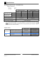
Gas Supply Requirements - UK Models Only
Appliance Classification
II2H3P.
A1.
Category:
Flue Type:
Natural Gas (G20)
Open Burner
Griddle
Heat Input (nett)
Gas Rate (nett)
Nominal
Reduced
Nominal
Reduced
Supply Pressure
Burner Operating Pressure
(each)
(each 300mm section)
6.5 kW
1.75 kW
0.69 m3/hr
0.19 m3/hr
5.5 kW
1.85 kW
0.58 m3/hr
0.20 m3/hr
Propane (G31)
Open Burner
Griddle
(each)
(each 300mm section)
6.5 kW
1.75 kW
0.51 kg/hr
0.14 kg/hr
5.5 kW
1.95 kW
0.43 kg/hr
0.15 kg/hr
20 mbar
37 mbar
9.5 mbar (*)
26 mbar (*)
Gas Connection (G512)
½" BSP male thread
Gas Connection (G514/6/8)
¾" BSP male thread
* - The burner operating pressure is to be measured at the manifold test point with two
burners operating at full setting. The operating pressure is ex-factory set, through the appliance
regulator and is not to be adjusted, apart from when converting between gases, if required. (Refer to
the ‘Gas Conversion’ section for details).
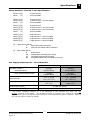
Injector Sizes
Open Burner
Natural. Gas
LP Gas (Propane)
Main Burner Injectors (Non-UK)
Ø 2.45 mm
Ø 1.50 mm
Main Burner Injectors (UK Only)
Ø 2.30 mm
Ø 1.40 mm
0.30
0.20
Main Burner
Ø 2.10 mm
Ø 1.30 mm
Pilot Burner
0.35
0.23
Pilot Burner ('PF' Option Only)
Griddle
2
Blue Seal Evolution series G51 Gas Cooktops
Revision 1/
© Moffat Ltd, January 2007
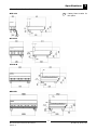
Specifications
1
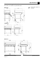
Dimensions for Bench Models
G512-B
R
= Rating Plate Location for
this option.
R
G514-B
G516-B
G518-B
3
Blue Seal Evolution series G51 Gas Cooktops
Revision 1/
© Moffat Ltd, January 2007
1
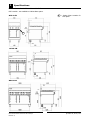
Specifications
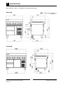
Dimensions for Cabinet Base Models
G512 models - not available in Cabinet Base option.
G514-CB
R
= Rating Plate Location for
this option.
R
G516-CB
G518-CB
4
Blue Seal Evolution series G51 Gas Cooktops
Revision 1/
© Moffat Ltd, January 2007
Specifications
1
Dimensions for Leg Stand Models
G512 models - not available in Leg Stand Base option.
G514-LS
R
= Rating Plate Location for
this option.
R
G516-LS
G518-LS
5
Blue Seal Evolution series G51 Gas Cooktops
Revision 1/
© Moffat Ltd, January 2007
1
Specifications
Dimensions for Refrigerated Base Models
G512 and G514 models - not available in Refrigerated Base option.
G516-RB
R
= Rating Plate Location for
this option.
R
G518-RB
6
Blue Seal Evolution series G51 Gas Cooktops
Revision 1/
© Moffat Ltd, January 2007
Specifications
1
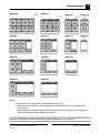
Cooktop Options
G518-D
G516-D
G514-D
G512-D
G518-C
G516-C
G514-C
G512-C
G518-B
G516-B
G514-B
G518-A
G516-A
NOTE:
• G512 models are only available in Bench Model (-B) option.
• G514 models are available in Bench Model (-B), Cabinet Base (-CB), or Leg Stand (-LS)
model options.
• G516 and G518 models are available in Bench Model (-B), Cabinet Base (-CB), Leg Stand
(-LS), or Refrigeration Base (-RB) model options.
For the Refrigeration Cabinet Specifications and Dimensions refer to the Refrigeration Cabinet
Installation and Operation Manual (Part No. 229093) supplied with the appliance.
7
Blue Seal Evolution series G51 Gas Cooktops
Revision 1/
© Moffat Ltd, January 2007
2
Installation
Installation Requirements
NOTE:
• It is most important that this Cooktop is installed correctly and that operation is
correct before use. Installation shall comply with local gas, health and safety
requirements.
• This appliance shall be installed with sufficient ventilation to prevent the occurrence
of unacceptable concentrations of health harmful substances in the room, the appliance is installed in.
Blue Seal Cooktops are designed to provide years of satisfactory service, and correct installation is
essential to achieve the best performance, efficiency and trouble-free operation.
This appliance must be installed in accordance with National installation codes and in addition, in
accordance with relevant National / Local codes covering gas and fire safety.
AUSTRALIA:
NEW ZEALAND:
UNITED KINGDOM:
-
IRELAND:
AS5601
- Gas Installations.
NZS5261
- Gas Installation.
Gas Safety (Installation & Use) Regulations 1998.
BS6173
- Installation of Catering Appliances.
BS5440 1 & 2
- Installation Flueing & Ventilation.
IS 820
- Non - Domestic Gas Installations.
Installations must be carried out by qualified service persons only. Failure to install equipment to the relevant codes and manufacturer’s specifications shown in this section will void
the warranty.
Components having adjustments protected (e.g. paint sealed) by the manufacturer are only
allowed to be adjusted by an authorised service agent. They are not to be adjusted by the installation person.
Unpacking
• Remove all packaging and transit protection from the appliance including all protective plastic
coating from the exterior stainless steel panels.
• Check equipment and parts for damage. Report any damage immediately to the carrier and distributor.
• Report any deficiencies to the distributor who supplied the appliance.
• Check that the available gas supply is correct to that shown on the Rating Plate attached to the underside of the R/ H side, front Cooktop lower trim, for Bench, Cabinet Base and Leg Stand Models.
For the Refrigerated Base Models the rating plate is located inside the right hand front panel and can
be viewed through the upper grille.
Combustion Air Requirements:
G512
3
G514
3
G516
3
G518
Natural Gas (G20)
12m /hr
24m /hr
36m /hr
48m3/hr
LPG/Propane (G31)
12m3/hr
25m3/hr
38m3/hr
50m3/hr
8
Blue Seal Evolution series G51 Gas Cooktops
Revision 1/
© Moffat Ltd, January 2007
Installation
2
Location
1.
2.
3.
4.
5.
Installation must allow for a sufficient flow of fresh air for the combustion air supply.
Installation must include adequate ventilation means, to prevent dangerous build up of combustion
products.
Never directly connect a ventilation system to the appliance flue outlet.
Position the appliance in its approximate working position.
All air for burner combustion is supplied from underneath the appliance. The legs must always be
fitted and no obstructions placed on the underside or around the base of the appliance, as
obstructions will cause incorrect operation and/or failure of the appliance.
NOTE: Do not obstruct or block the appliances flue. Never directly connect a ventilation system to the appliance flue outlet.
Combustible Surface
Non Combustible Surface
250 mm (*)
0 mm
50 mm
0 mm
Left / Right hand side
Rear
Clearances
NOTE: Only non-combustible materials can be used in close proximity to this appliance.
*
Side clearances can be 50 mm when the adjacent surface is at least 100 mm below the cooking surface.
Assembly
NOTE:
• All Models are delivered completely assembled. No further assembly is required, with
the exception of all Leg Stand Models (G514-LS, G516-LS G518-LS), these will
require assembly. Refer to the information below for assembly instructions.
• This appliance is fitted with adjustable feet to enable the appliance to be positioned
securely and level. This should be carried out on completion of the gas connection.
Refer to the ‘Gas Connection’ section.
Optional Accessories (Refer to Replacement Parts List)
•
Plinth Kit. For installation details, refer to the instructions supplied with each kit.
Bench Models
1.
Check that all the feet (and castors) are securely fitted.
2.
Adjust the feet to make the Cooktop steady and level.
9
Blue Seal Evolution series G51 Gas Cooktops
Revision 1/
© Moffat Ltd, January 2007
2
Installation
Gas Connection
NOTE: ALL GAS FITTING MUST ONLY BE CARRIED OUT BY A QUALIFIED PERSON.
1.
2.
Blue Seal Cooktops do not require electrical connection, as they function totally on the gas supply.
It is essential that the gas supply is correct for the Cooktop to be installed and that adequate
supply pressure and volume are available. The following checks should therefore be made before
installation:a. Gas Type the appliance has been supplied for is shown on a coloured stickers located above the
gas entry point and next to the rating plate. Check that this is correct for the gas supply the
appliance is being installed for. The gas conversion procedure is detailed in this manual.
b. Supply Pressure required for this appliance is shown in the ‘Specifications’ section of this
manual. Check the gas supply to ensure that adequate supply pressure exists.
c. Input Rate of this appliance is stated on the Rating Plate and in the ‘Specifications’ section of
this manual. The input rate should be checked against the available gas supply line capacity.
Particular note should be taken if the appliance is being added to an existing
installation.
NOTE: It is important that adequately sized piping runs directly to the connection joint on the
appliance with as few tees and elbows as possible, to give maximum supply volume.
3.
Fit the gas regulator supplied, into the gas supply line as close to the appliance as possible.
NOTE: The gas pressure regulator provided with this appliance is convertible between Natural
Gas and LPG and is already converted ex-factory to the gas type labelled beside the
gas connection point. The regulator outlet pressure is fixed ex-factory and it is NOT to
be adjusted.
For G512C-B and G512D-B models, the connection to the appliance is ½" BSP male thread.
For all other models, the connection to the appliance is ¾" BSP male thread.
(Refer to the “Specifications” section for the gas supply location dimensions).
All models - the regulator supplied has ¾" BSP F/F connections.
NOTE: A Manual Isolation Valve must be fitted to the individual appliance supply line.
4.
5.
6.
Correctly locate the appliance into its final operating position and using a spirit level, adjust the legs
so that the appliance is level and at the correct height.
Connect the gas supply to the appliance. A suitable joining compound which resists the breakdown
action of LPG must be used on every gas line connection, unless compression fittings are used.
Check all gas connections for leakages using soapy water or other gas detecting equipment.
WARNING:
DO NOT USE A NAKED FLAME
7.
TO CHECK FOR GAS LEAKAGES.
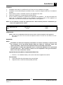
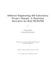
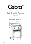
Check that the gas operating pressure is as
shown in ‘Specifications’ section.
NOTE: The operating pressure to be measured at
the manifold test point and with 2 burners
operating at the ‘High Flame’ setting.
8.
9.
10.
Turn off the mains gas supply and bleed the
gas out of the appliance gas lines.
Turn on the gas supply and the appliance.
Verify that the operating pressure remains
correct.
Manifold
Test Point
Fig 1
10
Blue Seal Evolution series G51 Gas Cooktops
Revision 1/
© Moffat Ltd, January 2007
Installation
2
Commissioning
Before leaving the new installation;
Check the following functions in accordance with the operating instructions specified in the
‘Operation’ section of this manual.
•
Lighting the Griddle.
•
Light the Open Burners. (F - Option).
•
Light the Open Burners. (PF - Option).
•
Check the Low Fire burner operation.
Ensure that the operator has been instructed in the areas of correct lighting, operation, and
shutdown procedure for the appliance.
This manual must be kept by the owner for future reference and a record of the Date of Purchase, Date
of Installation and Serial Number of Appliance recorded and kept with this manual. (These details
can be found on the Rating Plate;
For Bench, Cabinet Base and Leg Stand Models, the Rating Plate is attached to the underside
of the right hand side, front Cooktop lower trim.
For the Refrigerated Base Model, the Rating Plate is located inside the right hand front panel
and can be viewed through the upper grille. Refer to the ‘Gas Connection’ section and the
‘Dimensions’ section.
NOTE: If for some reason it is not possible to get the appliance to operate correctly, shut off
the gas supply and contact the supplier of this appliance.
For the Refrigeration Cabinet Installation details refer to the Refrigeration Cabinet Installation and
Operation Manual (Part No. 228093) supplied with11the appliance.
Blue Seal Evolution series G51 Gas Cooktops
Revision 1/
© Moffat Ltd, January 2007
3
Operation
3.1
Note:
Description of controls
A full user’s operation manual is supplied with the product and can be used for further referencing
of installation, operation and service.
C AUTIO N
• This appliance is for professional use and is only to be used by qualified
persons.
• Only authorised service persons are allowed to carry out installation,
servicing or gas conversion operations.
• Components
having adjustments protected (e.g. paint
manufacturer should not be adjusted by the user/operator.
sealed)
by
the
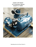
Gas Control Knobs
Griddle & Open Burners
with 'PF' Option fitted.
Burner Control
OFF Position
PILOT Burner
HIGH Flame
LOW Flame
Piezo Igniter
(Griddles Only)
Open Burner 'F' Option
Only
OFF Position
HIGH Flame
LOW Flame
Rear Burner
Front Burner
(Indicators located above
the Gas Control Knobs).
12
Blue Seal Evolution series G51 Gas Cooktops
Revision 1/
© Moffat Ltd, January 2007
Operation
3.2
3
Explanation of Control
System
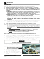
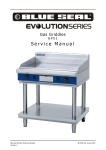
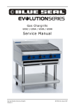
Safety System
Electromagnetic Flame Failure Gas Valve
The purpose of the safety system is to shut off
the flow of gas if the pilot flame goes out. It is
comprised of the flame itself, the thermocouple,
and the flame failure gas valve.
The purpose of the safety valve is to shut off the
flow of gas if the pilot flame goes out.
Inside the body of the gas valve is an
electromagnet connected to a spring loaded
plunger. When the electromagnet is energized, it
holds the plunger in, allowing gas to flow through
the valve.
When the electromagnet is
de-energized, the plunger snaps to the closed
position, stopping the flow of gas.
The pilot flame is lit by holding in the gas
control knob, which in turn temporarily pushes
the plunger inside the safety valve open and
allows gas to flow through. Once the burner is
lit, the thermocouple will begin to generate
millivolts (after about 10 to 30 seconds of being
heated) and will energize the electromagnet
inside the gas valve.
Once energized the
electromagnet holds the plunger inside the gas
valve in the open position. The plunger has to
have been pushed all the way in for the
electromagnet to be able to hold it in place. If
the burner flame goes out for some reason, the
thermocouple will cool after about 10 to 30
seconds and stop generating millivolts. The
electromagnet will then de-energize, and the
plunger will snap shut, cutting off the flow of gas.
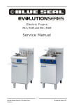
Thermocouple
Electromagnet
Plunger
Gas flow
Shaft
Knob
Detail of each component in the safety system is
explained below.
Gas flow
Plunger
Thermocouple
The thermocouple is a device that generates
electricity when heat is applied to the tip.
Insulator
Internal
Wire
Nut
Conductor
Figure 3.2b
Tip
Millivolts are provided to the electromagnet by
the thermocouple (not shown) which generates
millivolts when heated. The thermocouple screws
into a fitting at the back of the gas valve to make
an electric connection. By pressing in the gas
control knob, the plunger can be temporarily held
open while lighting. There's two reasons for this;
gas has to flow through the safety valve to make
it possible to light the pilot burner, and secondly
the plunger has to be pushed all the way in for
the electromagnet to hold it in.
I.e.; the
electromagnet is strong enough to hold the
plunger in once there, but is not strong enough
to pull it in by itself. Sometimes a problem with
the flame not staying lit after releasing the button
can be attributed to not pushing the plunger all
the way in.
Figure 3.2a
The tip of the thermocouple is located in the pilot
burner flame, and the nut at the other end of the
thermocouple screws into the back of the gas
valve. Inside the copper tubing is a wire which is
joined at the tip but insulated from the rest of the
tubing. These two parts (the copper tubing and
wire) make up the "wiring" for an electrical
circuit. When these two dissimilar metals, wire
and tip, are heated an electrical voltage is
produced. This type of thermocouple generates
between 7 and 30 millivolts when heated in the
pilot flame.
13
Blue Seal Evolution series G51 Gas Cooktops
Revision 1/
© Moffat Ltd, January 2007
4
Cleaning / Maintenance
CAUTION:
Always turn off the gas supply before cleaning.
This unit is not water proof.
Do not use water jet spray to clean interior or exterior of this appliance.
4.1
Cleaning Procedure
Routine Maintenance
After Each Use
To achieve the best results cleaning must be
regular and thorough and all controls and
mechanical parts checked and adjusted
periodically by a competent serviceman. If any
small faults occur, have them attended to
promptly. Don't wait until they cause a complete
breakdown.
It is recommended that the
appliance is serviced every 6 months.
Clean the griddle and cooktop castings with a stiff
nylon brush or a flexible spatula to remove any
build up of carbon.
Daily Cleaning
The grease tray(s) should be checked and
emptied frequently to prevent overflow and
spillage.
Remove the grease tray(s) while still warm so
that the grease is in a liquid state. Empty any
grease from the trays and wash thoroughly in the
same manner as any cooking utensil.
Clean the cooktop regularly. A clean cooktop
looks better, will last longer and will perform
better. Carbonised grease on the surface or
between the trivets, griddle plates will hinder the
transfer of heat from the cooking surface to the
food. This will result in loss of cooking efficiency.
Remove the griddle plate, burner caps and bases
and the trivets and thoroughly clean the splash
back and exterior surfaces of the cooktop with
hot water, a detergent solution and a soft
scrubbing brush.
DO NOT use water on the trivets, burners and
griddle plates while these items are still hot as
warping and cracking may occur. Allow these
items to cool down and then remove for cleaning.
The entire trivets, griddle plates and burner caps
can be dismantled for cleaning.
Dry the cooktop thoroughly with a dry cloth and
polish with a soft dry cloth.
Brush the griddle and trivets with a wire brush
followed by wiping with a cloth to prevent
accumulation of carbon.
NOTE:
DO NOT use abrasive detergents, sharp scrapers,
strong solvents or caustic detergents as they
could corrode or damage the cooktop.
In order to prevent the forming of rust on the
trivets, griddle plate (if fitted) and burners,
ensure that any detergent or cleaning material
has been completely removed after each
cleaning. The appliance should be switched on
briefly to ensure the griddle plates become dry.
Oil or grease should be spread over the griddle
surface in order to form a thin protective greasy
film.
To keep your cooktop clean and operating at
peak efficiency, follow the procedures shown
below:-
14
Blue Seal Evolution series G51 Gas Cooktops
Revision 1/
© Moffat Ltd, January 2007
Cleaning / Maintenance
Weekly Cleaning
4
use a griddle stone or a scotch bright pad on
the griddle surface.
Note:
b) A scraper tool can be used for the removal of
stubborn carbon and deposits.
• If the cooktop usage is very high, we recommend that the weekly cleaning procedure is
carried out on a more frequent basis.
c) Occasionally bleach the griddle plate with
vinegar when the plate is cold.
• Ensure that protective gloves are worn during
the cleaning process.
d) Clean with hot water, a mild detergent solution and a scrubbing brush. Dry all components thoroughly with a dry cloth.
• DO NOT use harsh abrasive detergents, sharp
scrapers, strong solvents or caustic detergents as they will damage the cooktop, burners and plates.
e) The griddle should be switched on briefly to
ensure that the griddle plate becomes dry. A
thin smear of cooking oil should be spread
over the grates in order to form a protective
film.
• DO NOT use water on the trivets, griddle
plates and burners while they are still hot as
cracking may occur.
Allow these items
castings to cool and remove for cleaning.
Trivets and Burners
a) Remove the trivets from the top of the appliance, taking note that the trivets are manufactured with a lip on one edge, the lip must
always be fitted to the outer edge (front and
back) of the range.
• DO NOT clean the burners in a dishwasher.
Cooking Area
b) Remove the burner cap and burner bowl
(these are a loose fit to the burner) from the
top of the gas manifold, taking care not to
damage the thermocouple fitted through the
manifold splash guard.
a) Clean the cooking area using a soft cloth
moistened with a mild detergent and hot
water solution.
b) Baked on deposits or discolouration may
require a good quality stainless steel cleaner
or stainless steel wool. Always apply cleaner
when the appliance is cold and rub in the
direction of the grain.
c) The trivets and burners should be cleaned
with a mild detergent and hot water solution
using a soft bristled brush. Dry thoroughly
with a dry cloth.
c) It should not be necessary to remove the
splash guards covering the burner manifolds
for cleaning purposes. These can be cleaned
in situ.
Trivet Supports
a) Remove all the trivet supports from the top of
the appliance. Take note of the orientation of
the trivet support when removing. The trivet
support front end side rail profiles are different from the rear end side rail profiles. (See
d) Remove the grease tray and clean with a mild
anti bacterial detergent and hot water solution using a soft bristled brush.
e) Dry the grease tray thoroughly with a dry
cloth.
the Note shown at Item a in ‘Re-Fitting the
Components to the Range’ below).
b) The trivet supports should be cleaned with a
mild detergent and hot water solution using a
soft bristled brush.
Griddle Plate
Note: In order to prevent the forming of rust on
the griddle plate, ensure the detergent or cleaning material has been entirely removed after
each cleaning process. The appliance should be
switched on briefly to ensure the griddle plates
become dry. Oil or grease should be spread over
the griddle surface in order to form a thin protective greasy film.
c) Dry the trivet supports thoroughly with a dry
cloth.
Stainless Steel Surfaces
a) With the griddle plates and burners removed,
clean the interior and exterior surfaces of the
range with hot water, a mild detergent
a) Clean the griddle surface thoroughly with a
wire brush or a flexible spatula. If necessary
15
Blue Seal Evolution series G51 Gas Cooktops
Revision 1/
© Moffat Ltd, January 2007
4
Cleaning / Maintenance
solution and a soft scrubbing brush. Note
that the gas control knobs are a push fit onto
the gas control valve spindles and can be
removed to allow cleaning of the front control
panel.
c) Refit the top part of the burner (cast brass)
onto the lower portion already fitted to the
manifold. This is a loose fit into the lower
part of the burner.
d) Refit the trivets to the top of the appliance,
taking note that the trivets are manufactured
with a lip on one edge, the lip must always be
fitted to the outer edge (front and back) of
the range.
b) Baked on deposits or discolouration may
require a good quality stainless steel cleaner
or stainless steel wool. Always apply cleaner
when the appliance is cold and rub in the
direction of the grain.
e) Refit the grease tray(s) to the range.
c) It should not be necessary to remove the
splash guards covering the burner manifolds
for cleaning purposes. These can be cleaned
in situ.
d) Dry all components thoroughly with a dry
cloth and polish with a soft dry cloth.
e) To remove any discolouration, use an approved stainless steel cleaner or stainless
steel wool. Always rub in the direction of the
grain.
f) Remove the grease tray and clean with a mild
anti bacterial detergent and hot water solution using a soft bristled brush.
g) Dry the grease tray thoroughly with a dry
cloth.
Re-Fitting the Components to the Range
a)
Refit the trivet supports to the range, ensuring that the trivet supports are correctly fitted.
Note: It is imperative that the trivet supports
are correctly re-fitted to the appliance to ensure
that the trivets locate correctly and sit flush and
level. NOTE that the trivet support front end,
side rail profiles are different at either side and
only one of the side rails seat into the cut-out in
the range top. where as the rear end of the trivet
support side rail profiles are the same and have 2
cut-outs to locate into.
b) Refit the lower cast portion of the 2 piece
burners onto the manifolds protruding
through the splash guards, taking care not to
damage the thermocouple which is close to
the manifold.
Note: The burner bowl (cast item) has 2 locating holes drilled into the base flange, these are to
locate the base of the burner to the cap screw on
the gas manifold when re-fitting the burner onto
the gas manifold.
16
Blue Seal Evolution series G51 Gas Cooktops
Revision 1/
© Moffat Ltd, January 2007
Cleaning / Maintenance
4.2
4
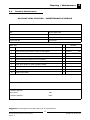
Routine Maintenance
G51 BLUE SEAL COOKTOP - MAINTENANCE SCHEDULE
Business Name and Address:
Date:
Service Report No.
Phone:
Fax:
Serial No:
Clients Order No.
Serviceman:
Remarks
Model: G51
1
Inspect exterior condition of unit.
2
Check working gas pressure correct to rating plate.
3
Regrease gas cocks (Cooktop / Griddle if fitted).
4
Inspect thermocouples (cooktop, griddle-if fitted).
5
Replace all thermocouples (every 12 months)
6
Inspect injectors are clean and free from blockages.
7
Check piezo ignition of pilots (griddle-if fitted).
8
Check pilot flames.
9
Check for gas tightness.
10
Check for gas leaks.
Pressure _______ kPa
Service Comments:
Additional work/repairs required:
Customers approval:
Name (print):
Title:
Customers signature:
Date:
Suggestion: Photocopy this form and keep on file for continued use.
17
Blue Seal Evolution series G51 Gas Cooktops
Revision 1/
© Moffat Ltd, January 2007
5
Trouble-shooting
WARNING:
5.1
ALL INSTALLATION AND SERVICE REPAIR WORK MUST BE CARRIED OUT BY
QUALIFIED PERSONS ONLY.
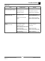
Trouble Shooting Chart
Open burners
Fault
Pilot won’t light
(PF fitted burners only)
Main burners will not light.
Main burners go out when control
knob released.
Possible cause
Remedy
Gas control knob not being held
in.
Hold in button while lighting pilot.
No gas supply.
Ensure gas is connected and on
(bottles not empty).
Gas pressure too low.
Check gas supply pressure.
(Refer specifications section)
Blocked pilot injector.
Clean or replace pilot injector.
(Refer service section 6.2.5)
Gas control faulty.
Replace.
(Refer service section 6.2.4)
Wrong size or blocked injectors.
Replace / clean injectors.
(Refer service section 6.2.2)
Obstruction in burner.
Clean burner.
Incorrect supply pressure.
Check supply pressure.
Faulty gas control.
Replace gas control.
(Refer service section 6.2.4)
Releasing knob before
thermocouple heated.
Hold control knob in for longer
(10 secs) after lighting the burner.
Pilot too small (PF burners only)
Check gas supply pressure
(Refer specifications section)
Clean or replace pilot injector
(Refer service section 6.2.5)
Low fire rate too high.
Burner goes out when set to low
position.
Thermocouple incorrectly
positioned.
Reposition correctly.
Thermocouple faulty.
Replace.
(Refer service section 6.2.3)
Gas valve magnet faulty.
Replace.
Incorrect supply pressure.
Check supply pressure.
Low fire adjustment incorrect.
Adjust.
(Refer service section 6.4.2)
Incorrect supply pressure.
Check / adjust pressure.
Low fire rate set too low.
Check adjust low fire rate.
(Refer service section 6.4.2)
18
Blue Seal Evolution series G51 Gas Cooktops
Revision 1/
© Moffat Ltd, January 2007
Trouble-shooting
5
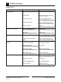
Open burners
Fault
Main burner flame
incorrect colour (yellow / wavy)
Pilot flame small / lazy / yellow.
(PF fitted burners only)
Pilot goes out when knob
released.
(PF fitted burners only)
Possible cause
Remedy
Incorrect gas pressure.
Check supply pressure.
Incorrect injector size.
Check injector correct size.
Obstruction in burner.
Inspect burner for obstruction.
Gas pressure too low.
Check gas supply pressure.
(Refer specifications section)
Blocked / incorrect size pilot
injector.
Clean or replace pilot injector.
(Refer service section 6.2.8)
Releasing knob before the
thermocouple is heated.
Hold control in for longer (10 s),
see if pilot will stay lit.
Pilot flame too small.
Correct fault.
(Refer fault:Pilot Flame Small)
Thermocouple faulty.
(Refer fault diagnosis 5.2.1)
Replace thermocouple.
(Refer service section 6.2.3)
Gas magnet faulty.
(Refer fault diagnosis 5.2.1)
Replace gas magnet.
(Refer service section 6.2.7)
19
Blue Seal Evolution series G51 Gas Cooktops
Revision 1/
© Moffat Ltd, January 2007
5
Trouble-shooting
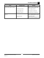
Griddle burners
Fault
Pilot won’t light
Piezo ignitor not sparking.
Pilot flame small / lazy / yellow.
Pilot goes out when knob
released.
Possible cause
Remedy
Gas control knob not being held
in.
Hold in button while lighting pilot.
No gas supply.
Ensure gas is connected and on
(bottles not empty).
Gas pressure too low.
Check gas supply pressure.
(Refer specifications section)
Blocked pilot injector.
Clean or replace pilot injector.
(Refer service section 6.2.8)
Gas control faulty.
Replace.
(Refer service section 6.2.12)
Short in high tension lead.
(Refer fault diagnosis 5.2.2)
Replace lead.
(Refer service section 6.2.11)
Piezo faulty.
(Refer fault diagnosis 5.2.2)
Replace piezo.
(Refer service section 6.2.14)
Gas pressure too low.
Check gas supply pressure.
(Refer specifications section)
Blocked / incorrect size pilot
injector.
Clean or replace pilot injector.
(Refer service section 6.2.8)
Releasing knob before the
thermocouple is heated.
Hold control in for longer (10 s),
see if pilot will stay lit.
Pilot flame too small.
Correct fault.
(Refer fault:Pilot Flame Small)
Main burners will not light.
Thermocouple faulty.
(Refer fault diagnosis 5.2.1)
Replace thermocouple.
(Refer service section 6.2.9)
Gas magnet faulty.
(Refer fault diagnosis 5.2.1)
Replace gas magnet.
(Refer service section 6.2.13)
Wrong size or blocked injectors.
Replace / clean injectors.
(Refer service section 6.2.6)
Obstruction in burner.
Clean burner.
Incorrect supply pressure.
Check supply pressure.
Faulty gas control.
Replace gas control.
(Refer service section 6.2.12)
20
Blue Seal Evolution series G51 Gas Cooktops
Revision 1/
© Moffat Ltd, January 2007
Trouble-shooting
Fault
Main burner flame
incorrect colour (yellow / wavy).
Pilot goes out when main burner
comes on.
Possible cause
5
Remedy
Aeration setting incorrect.
Adjust aeration.
(Refer service section 6.4.4)
Incorrect gas pressure.
Check supply pressure.
Incorrect injector size.
Check injector correct size.
Obstruction in burner.
Inspect burner for obstruction.
Incorrect gas pressure.
Check supply / adjust pressure.
(Refer specifications section)
Faulty gas control.
Replace gas control.
(Refer service section( 6.2.12)
21
Blue Seal Evolution series G51 Gas Cooktops
Revision 1/
© Moffat Ltd, January 2007
5
Trouble-shooting
5.2.2
5.2
Fault diagnosis
5.2.1
Pilot goes out when pilot
knob is released
Piezo ignitor not sparking
Short in high tension lead
If repeated sparking of the piezo shows
intermittent sparking at the electrode, then the
lead should be traced to find area of short. This
can normally be visually seen as the spark arcs.
If the lead is shorting the best solution is to
replace it, as the electrical insulation strength of
the lead may have deteriorated.
Pilot flame too small
If pilot can be lit but the flame is too small to impinge on the thermocouple, then check the gas
pressure. If ok, remove pilot injector from pilot
burner and check for blockages and/or correct
size.
If the spark arc can be seen at the electrode
insulator at the pilot burner instead of at the
electrode tip, then the insulator probably has a
fracture and should be replaced.
Thermocouple faulty
Inspect thermocouple for build-up of carbon or
food deposits on the tip.
Clean off any
deposits, taking care not to scratch off the
aluminium coating on the thermocouple.
Piezo ignitor faulty
If no spark at all can be generated, remove piezo
ignitor and hold close to the hob body, depress
piezo ignitor and if a spark cannot be generated
to hob body the piezo ignitor is faulty and should
be replaced.
Check that the thermocouple tip is in the flame
zone of the pilot burner. When the burner is lit,
the flame should impinge on the top 5mm of the
thermocouple tip.
NOTE: If piezo ignition fails, the pilot can be
manually lit in the interim until the piezo circuit is
repaired. A standard taper torch or matches/
lighter can be used for manual back-up ignition.
NOTE: The thermocouple should not touch the
burner.
Check
thermocouple
connection
to
gas
control is firm (loose connections will cause resistance in millivolt circuit and result in pilot outage).
If connection is OK, then disconnect the
thermocouple from the gas control, light the pilot,
and whilst holding the control knob in,
measure voltage between the thermocouple internal wire (refer figure 5.2.1) and earth (e.g. the
body of the gas control). This should read approximately 30mV. If this reading is less than
10mV then the thermocouple is faulty—replace.
Tip
Internal Wire
Figure 5.2.1
Gas magnet faulty
If thermocouple milli-voltage is above 10mV, and
the pilot still will not hold, then the gas magnet is
faulty - replace.
22
Blue Seal Evolution series G51 Gas Cooktops
Revision 1/
© Moffat Ltd, January 2007
Service Procedures
Section
6
Page no.
6.1 Access .................................................................................................... 24
6.1.1
Hob Control Panel .................................................................................................... 24
6.2 Replacement ........................................................................................... 24
6.2.1
6.2.2
6.2.3
6.2.4
6.2.5
6.2.6
6.2.7
6.2.8
6.2.9
6.2.10
6.2.11
6.2.12
6.2.13
6.2.14
6.2.15
Open Burner Venturi ................................................................................................ 24
Open Burner Injector ............................................................................................... 25
Open Burner Thermocouple ...................................................................................... 26
Open Burner Gas Control .......................................................................................... 27
Open Burner Pilot (PF Models) .................................................................................. 27
Griddle Burner Gas Control ...................................................................................... 28
Griddle Control Magnet............................................................................................. 28
Griddle Burner ......................................................................................................... 28
Griddle Burner Injector ............................................................................................. 29
Griddle Pilot Burner .................................................................................................. 29
Griddle Pilot Burner Thermocouple ............................................................................ 29
Griddle Pilot Burner Injector...................................................................................... 30
Griddle Pilot Burner Spark Electrode ......................................................................... 30
Griddle Burner H.T Lead ........................................................................................... 30
Piezo Igniter ............................................................................................................ 30
6.3 Adjustment / Calibration ....................................................................... 31
6.3.1
6.3.2
6.3.3
Cooktop Gas Tap Re-greasing ................................................................................... 31
Cooktop Low Fire Adjustment ................................................................................... 31
Burner Aeration ....................................................................................................... 31
WARNING:
ALL INSTALLATION AND SERVICE REPAIR WORK MUST BE CARRIED OUT BY
QUALIFIED PERSONS ONLY.
ENSURE GAS SUPPLY IS SWITCHED OFF BEFORE SERVICING
ALWAYS CHECK / TEST FOR GAS LEAKS AFTER SERVICE REPAIRS ON THE GAS
SYSTEM
23
Blue Seal Evolution series G51 Gas Cooktops
Revision 1/
© Moffat Ltd, January 2007
6
Service Procedures
6.1
Access
6.2
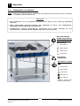
6.1.1
Hob control panel
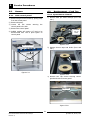
6.2.1 Open Burner Venturi
Replacement – Cook Top
1) Remove both pot stand castings (front and
rear ).
1) Remove all gas control knobs by pulling away
from the control panel.
2) Remove drip tray.
3) Loosen the two screws
control panel to the hob.
securing
the
3) Remove the control panel.
Front and
rear pot
stands
4) Griddle models will require H.T lead to be
disconnected from rear of piezo ignitor on
control panel.
Figure 6.2.1a
Gas control knobs
2) Remove burner caps and bowls (front and
rear ).
Drip tray
Two screws
Caps and bowls
Figure 6.1.1
Figure 6.2.1b
3) Remove two cap screws securing burner
guard and remove burner guard.
Cap screws
Figure 6.2.1c
24
Blue Seal Evolution series G51 Gas Cooktops
Revision 1/
© Moffat Ltd, January 2007
Service Procedures
6
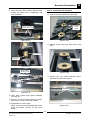
6.2.2 Open burner injector
4) Undo two cap screws securing thermocouple
bracket and (Pilot burner if applicable) and
remove bracket.
1) Remove both pot stands (front and rear).
Front and
rear pot
stands
Bracket cap screws
Figure 6.2.1d
Figure 6.2.2a
2) Remove burner caps and bowls (front and
rear).
Securing nut
Open burner
injector
Caps and bowls
Figure 6.2.1e
Burner venture
securing screws
Figure 6.2.2b
3) Remove two cap screws securing burner
guard and remove burner guard.
Cap screws
Figure 6.2.1f
5) Undo main injector and injector assembly
securing nut.
6) Remove two screws securing burner venturi
and remove burner venturi and replace.
7) Reassemble in reverse order.
NOTE: ensure when reassembling that burner
bowls are seated correctly on cap screw
heads.
Figure 6.2.2c
25
Blue Seal Evolution series G51 Gas Cooktops
Revision 1/
© Moffat Ltd, January 2007
6
Service Procedures
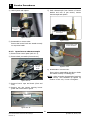
4) Undo injector and replace.
5) Undo thermocouple from bottom of burner
bracket and rear of gas control, remove
thermocouple and replace.
Open burner
injector
Thermocouple bracket
securing nut
Figure 6.2.2d
Figure 6.2.3c
5) Reassemble in reverse order.
Ensure that burner bowls are seated correctly
on cap screw heads.
6.2.3
Thermocouple to gas
control connection
Open burner thermocouple
1) Remove front control panel (refer 6.1.1).
2) Remove both pot stands (front and rear).
Front and
rear pot
stands
Figure 6.2.3d
6) Reassemble in reverse order.
Ensure when reassembling that burner bowls
are seated correctly on locating pins.
NOTE: When screwing thermocouple back into
gas control, once threaded up tighten up
another ¼ turn only. Do not over-tighten.
Figure 6.2.3a
3) Remove burner caps and bowls (front and
rear).
4) Remove two cap screws securing burner
guard and remove burner guard.
Cap screws
Figure 6.2.3b
26
Blue Seal Evolution series G51 Gas Cooktops
Revision 1/
© Moffat Ltd, January 2007
Service Procedures
6.2.4
Open burner gas control
6
6.2.5 Open burner pilot (PF models)
1) Remove control panel (refer 6.1.1 access).
1) Remove both pot stands (front and rear).
2) Undo open burner gas supply line from gas
control.
2) Remove burner caps and bowls (front and
rear).
3) Remove two screws securing each pilot
burner shield.
Gas control
supply connection
2 Pilot Burner Shield
Screws
Open burner
gas supply line
Figure 6.2.4a
3) Undo thermocouple from rear of gas control.
Undo manifold supply connection to gas
control.
Figure 6.2.5a
4) Remove two cap screws securing burner
guard and remove burner guard.
4) Remove pilot supply line from gas control
( Pilot flame models only).
5) Unscrew the pilot supply tube from the
pilot injector case.
Thermocouple to gas
control connection
6) Undo one screw securing pilot injector case
bracket and slide injector case away from the
pilot tube.
Figure 6.2.4b
5) Remove gas control.
6) Replace and re-assemble in reverse order.
7)
Check for gas leaks.
Pilot injector case
NOTE: When screwing thermocouple back into
gas control, once threaded up tighten up
another ¼ turn only. Do not over-tighten.
Figure 6.2.5b
7) Undo injector case screw and remove pilot
injector.
8) Clean or replace as necessary,
reassemble in reverse order.
and
Ensure when reassembling that burner bowls
are seated correctly on locating pins.
27
Blue Seal Evolution series G51 Gas Cooktops
Revision 1/
© Moffat Ltd, January 2007
6
Service Procedures
6.2.7
Gas control magnet
1) Remove the burner (refer 6.3.1 / 6.3.8) and
the heat shield.
2) Remove the thermocouple from the rear of
the gas control (refer figure 6.3.22).
Spring
Injector
3) Remove the rear nut from gas control.
Cap
4) Extract gas magnet.
5) Replace and reassemble in reverse order.
Figure 6.2.5c
6.2.6
Griddle burner gas control
1) Remove control panel.
2) Unscrew main burner supply, pilot burner
supply and thermocouple from gas control.
Magnet
Gas Control
3) Unscrew manifold connection to gas control
and remove gas control.
Rear Nut
Figure 6.2.7
Pilot supply
Manifold connection
6.2.8
Griddle burner
1) Remove griddle plate.
2) Unscrew the 3/16" screw at rear of burner.
Thermocouple
Securing screw
Main supply line
Figure 6.2.6
4) Replace and reassemble in reverse order.
NOTE: When screwing thermocouple back into
gas control, once threaded up tighten up
another ¼ turn only. Do not over-tighten.
Figure 6.2.8
3) Remove burner, replace and reassemble in
reverse order.
28
Blue Seal Evolution series G51 Gas Cooktops
Revision 1/
© Moffat Ltd, January 2007
Service Procedures
6.2.9
Griddle burner injector
6
5) Remove pilot burner from bracket (two
screws).
1) Remove griddle plate.
6) Replace and reassemble in reverse order.
2) Remove griddle burner (refer 6.2.10).
Ensure that the thermocouple is
NOTE:
positioned correctly in the holder before
tightening up.
3) Lift out stainless steel reflector plate.
Burner
6.2.11 Griddle pilot burner
thermocouple
Reflector
plate
1) Remove griddle plate and reflector plate.
2) Remove griddle burner (refer 6.2.10).
3) Unscrew the pilot thermocouple from the
pilot burner assembly.
Thermocouple
Figure 6.2.9
4) Remove the griddle injector from the gas
assembly mounting.
5) Clean or replace as necessary,
reassemble in reverse order.
and
6.2.10 Griddle pilot burner
1) Remove griddle plate and reflector plate.
2) Remove griddle burner (refer 6.2.10).
Figure 6.2.11a
3) Unscrew the pilot supply tube, piezo
electrode, and thermocouple from pilot
assembly.
4) Undo two screws securing
bracket to griddle reflector.
pilot
4) Undo thermocouple from the griddle gas
control.
5) Replace and reassemble in reverse order.
burner
NOTE: When screwing thermocouple back into
gas control, once threaded up tighten up
another ¼ turn only. Do not over-tighten.
Two screws
Thermocouple
to gas control
connection
Figure 6.2.10
Figure 6.2.11b
29
Blue Seal Evolution series G51 Gas Cooktops
Revision 1/
© Moffat Ltd, January 2007
6
Service Procedures
6.2.12 Griddle pilot burner injector
6.2.14 Griddle burner H.T Lead
1) Remove griddle plate and reflector plate.
1) Remove control panel (refer 6.1.1).
2) Remove griddle burner (refer 6.2.10).
2) Remove H.T. lead from piezo ignitor and pilot
electrode.
3) Unscrew the pilot supply tube from the
pilot burner assembly.
Pilot supply
Figure 6.2.14
3) Replace lead and reassemble in reverse
order.
Figure 6.2.12
4) Extract injector from pilot burner.
5) Clean or replace as necessary,
reassemble in reverse order.
and
6.2.15 Piezo ignitor
1) Remove control panel (refer 6.1.1).
6.2.13 Griddle pilot burner spark
electrode
2) Remove the HT lead from the piezo ignitor by
pulling firmly away.
1) Remove griddle plate and reflector plate.
3) Unscrew the nut securing the piezo ignitor to
the control panel.
2) Remove griddle burner (refer 6.2.10).
3) Remove H.T lead from the rear of the spark
electrode.
Figure 6.2.1
Piezo electrode
Figure 6.2.13
4) Unscrew the spark electrode from the pilot
burner assembly.
5) Replace and reassemble in reverse order.
30
Blue Seal Evolution series G51 Gas Cooktops
Revision 1/
© Moffat Ltd, January 2007
Service Procedures
6.3
6.3.2
Adjustment/ calibration
6
Cooktop low fire adjustment
1) Light burner and turn gas tap to low position.
6.3.1
2) Remove gas control knob.
Cooktop gas tap re-greasing
3) Turn low fire adjustment screw, located below and to the right of the gas control shaft,
until the desired low flame is achieved.
1) Remove control panel (refer 6.1.1).
2) Remove 2 screws holding shaft plate to gas
control body and remove control shaft and
plate. Note orientation of shaft for correct
re-assembly.
Standard hob top gas control
Low fire screw
Two Screws
Figure 6.3.2
Figure 6.3.1a
6.3.3
3) Using needle nose pliers or similar, pull out
gas control spindle, again noting its
orientation.
Burner aeration
The griddle burners can all be adjusted to give
the most efficient flame. If the flame is yellow
and wavy, then the burner needs adjusting.
1) Loosen the aeration slide screw.
Spindle
Figure 6.31b
4) Apply a suitable high temperature gas cock
grease or lubricant such as ROCOL - A.S.P
(Anti scuffing paste) / Dry Moly Paste to the
outside of the spindle.
Aeration slide
5) Replace spindle and re-assemble gas control
in reverse order.
Aeration screw
Figure 6.3.3
2) Adjust the aeration slide as required.
The most efficient flame is clear blue/green in
colour.
31
Blue Seal Evolution series G51 Gas Cooktops
Revision 1/
© Moffat Ltd, January 2007
7
Accessories
32
Blue Seal Evolution series G51 Gas Cooktops
Revision 1/
© Moffat Ltd, January 2007
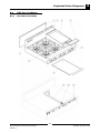
Exploded Parts Diagrams
8.1
G51 Gas Cooktops
8.1.1
G51 Main Assembly
8
33
Blue Seal Evolution series G51 Gas Cooktops
Revision 1/
© Moffat Ltd, January 2007
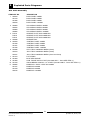
8
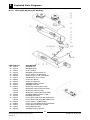
Exploded Parts Diagrams
G51 Main Assembly
ITEM PART NO
1 228670
227794
227836
228420
2 228809
228672
228669
228662
3 PG312
PG612
PG912
4 228288
5 229360
227538
227537
227236
6
230286
230273
230277
7 227014
8 227960
9 227690
10 227330
11 228692
227277
227278
228155
DESCRIPTION
BACK PANEL 300MM
BACK PANEL 600MM
BACK PANEL 900MM
BACK PANEL 1200MM
SPLASHBACK BSEAL 300MM
SPLASHBACK BSEAL 600MM
SPLASHBACK BSEAL 900MM
SPLASHBACK BSEAL 1200MM
GRIDDLE PLATE GAS 300MM WA
GRIDDLE PLATE GAS 600MM WA
GRIDDLE PLATE GAS 900MM WA
GREASE TRAY
CONTROL PANEL 300MM
CONTROL PANEL 600MM
CONTROL PANEL 900MM
CONTROL PANEL 1200MM
SPILL TRAY 300MM WA BSEAL (G512)
SPILL TRAY 450MM WA BSEAL (G516)
SPILL TRAY 600MM WA BSEAL (G514 and G518)
POT STAND
BLUE SEAL BADGE
HOB - RANGE SUPPLY PIPE (G514/6/8 ONLY - G512 SEE ITEM 11)
UNION BRASS CONICAL ½ X ¾ BSPT (G514/6/8 ONLY - G512 SEE ITEM 11)
MANIFOLD / SUPPLY PIPE WA 300MM
MANIFOLD 600MM
MANIFOLD 900MM
MANIFOLD 1200MM
34
Blue Seal Evolution series G51 Gas Cooktops
Revision 1/
© Moffat Ltd, January 2007
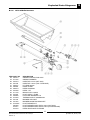
Exploded Parts Diagrams
8.1.2
8
G51 Open Burners (F Models)
ITEM PART NO
12 227017
13 227018
14 227455
15 227457
16 017802
17 017804
18 017803
19 227405
20 228167
21 227379
22 227019
23 030245
030230
030150
030140
24 227456
25 227132
26 228166
27 227627
DESCRIPTION
BURNER CAP
BURNER BODY
BURNER COVER PANEL STD
REAR BURNER SUPPLY PIPE
INLET SPIGOT 10MM
NUT - 10mm STEEL
OLIVE 10MM BRASS
GAS VALVE 20S-B CW 3-8 ELBOW
THERMOCOUPLE 320mm
KNOB BSEAL 8MM GAS STD / F
BURNER VENTURI
INJECTOR 2.45mm (NAT GAS)
INJECTOR 2.30mm (UK NAT GAS)
INJECTOR 1.50mm (LPG)
INJECTOR 1.40mm (UK PROPANE)
FRONT BURNER SUPPLY TUBE
BURNER SUPPORT
THERMOCOUPLE 600mm
THEMOCOUPLE SUPPORT BRKT WA
35
Blue Seal Evolution series G51 Gas Cooktops
Revision 1/
© Moffat Ltd, January 2007
8
Exploded Parts Diagrams
8.1.3
G51 Open Burners (PF Models)
ITEM PART NO
28 227017
29 227018
30 229444
31 227454
32 229426
33 227403
34 227378
35 229424
36 229425
37 228167
38 227019
39 030245
030230
030150
030140
40 227456
41 227132
42 026134
026136
43 229422
44 229880
45 229443
46 229442
47 228166
DESCRIPTION
BURNER CAP
BURNER BODY
PILOT SHIELD
BURNER COVER PANEL PF
PILOT SUPPLY TUBE REAR
GAS VALVE 21S CW 3-8 ELBOW
KNOB BSEAL 8mm GAS PF
PILOT NUT Ø4mm
PILOT OLIVE Ø4mm
THERMOCOUPLE 320mm
BURNER VENTURI
INJECTOR 2.45mm (NAT GAS)
INJECTOR 2.30mm (UK NAT GAS)
INJECTOR 1.50mm (LPG)
INJECTOR 1.40mm (UK PROPANE)
FRONT BURNER SUPPLY TUBE
BURNER SUPPORT
PILOT INJECTOR SPUD Ø0.30MM (NAT)
PILOT INJECTOR SPUD Ø0.20MM (LPG)
PILOT SUPPLY TUBE FRONT
PILOT SIT 100 SERIES INJECTOR BASE
PILOT INJECTOR BASE CLAMP
PILOT BRACKET WA
THERMOCOUPLE 600mm
36
Blue Seal Evolution series G51 Gas Cooktops
Revision 1/
© Moffat Ltd, January 2007
Exploded Parts Diagrams
8.1.4
8
G51 Griddle Burners
61
ITEM
48
49
50
50
51
52
53
54
55
56
57
58
59
60
61
PART NO
230213
014105
032210
032130
228047
228223
228010
227508
011148
227594
022686
019428
227178
227765
019215K
026488
019217
018744
DESCRIPTION
GRIDDLE REFLECTOR ASSY
GRIDDLE BURNER
INJECTOR 2.1mm (NAT GAS)
INJECTOR 1.3mm (LPG / PROPANE)
HT LEAD 250mm
PIEZO CLAMP
PIEZO HOUSING
PIEZO - SIT
BRASS PLUG 3152X4
PILOT SUPPLY TUBE
FLEXTUBE DORMONT T6
THERMOCOUPLE 320MM M9x1
BURNER SUPPORT
BURNER MOUNTING BRACKET
PILOT BURNER KIT
PILOT BURNER INJECTOR 0.35mm (NAT GAS)
PILOT BURNER INJECTOR 0.23mm (LPG/PROPANE)
PIEZO IGNITION ELECTRODE
37
Blue Seal Evolution series G51 Gas Cooktops
Revision 1/
© Moffat Ltd, January 2007
8
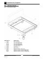
Exploded Parts Diagrams
8.2
G51 Base Options
8.2.1
Bench Mount Base
ITEM PART NO
1 230354
2 228663
227123
227120
227125
3 227855
4 227852
5 230355
6 228670
228313
227121
228314
DESCRIPTION
SIDE COVER RH
TOP TRIM 300MM WIDE
TOP TRIM 600MM WIDE
TOP TRIM 900MM WIDE
TOP TRIM 1200MM WIDE
LEG 80MM X Ø63.5
LEG PLATE
SIDE COVER LH
HOB BACK PANEL 300MM WIDE
HOB BACK PANEL SUPPORT 600MM WIDE
HOB BACK PANEL SUPPORT 900MM WIDE
HOB BACK PANEL SUPPORT 1200MM WIDE
38
Blue Seal Evolution series G51 Gas Cooktops
Revision 1/
© Moffat Ltd, January 2007
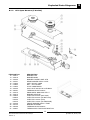
Exploded Parts Diagrams
8.2.2
ITEM
1
2
3
4
5
6
7
8
9
10
11
12
8
Cabinet Base
PART NO
227048
228321
227075
227901
227409
227790
227789
227791
227788
227787
227786
227850
227852
227049
229674
229671
227040
227104
227117
228935
DESCRIPTION
SIDE PANEL RH
SIDE RACK WA
SILL 600MM WA
SILL 900MM WA
SILL 1200MM WA
FILLER 600MM
FILLER 900MM
FILLER1200MM
SIDE SUPPORT 600MM
CENTRE SUPPORT 900MM
CENTER SUPPORT 1200MM
LEG 150MM X Ø63.5
LEG PLATE
SIDE PANEL LH
REAR ROLLER ASSEMBLY
LEG RING PLATE THREADED
BACK PANEL 600MM WIDE
BACK PANEL 900MM WIDE
BACK PANEL 1200MM WIDE
GAS HOUSING
39
Blue Seal Evolution series G51 Gas Cooktops
Revision 1/
© Moffat Ltd, January 2007
8
Exploded Parts Diagrams
8.2.3
Leg Base
ITEM PART NO
1 230354
2 227123
227120
227125
3 227853
4 227408
227407
227409
5 227075
227901
227902
6 227851
7 229674
8 748010
9 229673
10 230355
11 228313
228312
228314
DESCRIPTION
SIDE COVER RH
TOP TRIM 600MM
TOP TRIM 900MM
TOP TRIM 1200MM
LEG EXTENSION 530 X Ø63.5
BASE TRAY 600MM
BASE TRAY 900MM
BASE TRAY 1200MM
SILL 600MM WA
SILL 900MM WA
SILL 1200MM WA
LEG 150MM X Ø63.5 EXTD THREAD
REAR ROLLER ASSEMBLY
SCREW 5/8"X1 HEX SET ZP
LEG RING PLATE PLAIN
SIDE COVER LH
HOB BACK PANEL SUPPORT 600MM
HOB BACK PANEL SUPPORT 900MM
HOB BACK PANEL SUPPORT 1200MM
40
Blue Seal Evolution series G51 Gas Cooktops
Revision 1/
© Moffat Ltd, January 2007
Service Contacts
9
Australia
VICTORIA - MOFFAT PTY
HEAD OFFICE AND MAIN WAREHOUSE
740 Springvale Road
Mulgrave VIC 3170
Spare Parts Department
Tel (03) 9518 3888
Fax (03) 9518 3838
Free Call 1800 337 963
Fax (03) 9518 3895
NEW SOUTH WALES - MOFFAT PTY
Unit 3/142 James Ruse Drive
Rosehill NSW 2142
Spare Parts
Tel (02) 8833 4111
Free Call 1800 337 963
Fax (03) 9518 3895
QUEENSLAND - MOFFAT PTY
30 Prosperity Place
Geebung QLD 4034
Spare Parts
Tel (07) 3630 8600
Free Call 1800 337 963
Fax (03) 9518 3895
WESTERN AUSTRALIA - MOFFAT PTY
67 Howe St
Osbourne Park, WA 6017
Spare Parts
Tel (08) 9202 6820
Fax (08) 9202 6836
Free Call 1800 337 963
Fax (03) 9518 3895
NATIONAL COVERAGE FOR 24 HOUR SERVICE OR MAINTENANCE DIAL
FREE CALL 1800 622 216 (AUSTRALIA ONLY)
Canada
SERVE CANADA
22 Ashwarren Rd
Downview
Ontario M3J1Z5
Tel 416-631-0601
Fax 416-631-0315
New Zealand
CHRISTCHURCH - MOFFAT LTD
16 Osborne St
PO Box 10-001
Christchurch
Spare Parts
Tel (03) 389 1007
Fax (03) 389 1276
Free Call 0800 MOFFAT
(0800 66 33 28)
Fax (03) 381 3616
AUCKLAND - MOFFAT LTD
4 Waipuna Road
Mt Wellington
Auckland
Spare Parts
Tel (09) 574 3150
Fax (09) 574 3159
Free Call 0800 MOFFAT
(0800 66 33 28)
41
Blue Seal Evolution series G51 Gas Cooktops
Revision 1/
© Moffat Ltd, January 2007
9
Service Contacts
United Kingdom
BLUESEAL LTD
67 Gravelly Industrial Park
Erdington
Birmingham B24 8TQ
England
Tel 0121 327 5575
Fax 0121 327 9711
United States of America
MOFFAT INC.
3765 Champion Blvd
Winston-Salem
NC27115
Tel 1800 551 8795
Fax 336 661 9546
NATIONAL COVERAGE FOR SERVICE OR MAINTENANCE DIAL
FREE CALL 1800 551 8795 (USA ONLY)
42
Blue Seal Evolution series G51 Gas Cooktops
Revision 1/
© Moffat Ltd, January 2007
Appendix A: Gas Type Conversion
A
Gas type conversion procedure
NOTE:
• These conversions should only be carried out by qualified persons. All connections must
be checked for leaks before re-commissioning the appliance.
• For all relevant gas specifications refer to the table at the end of this section.
Open Burners ('F' - Flame Failure Option)
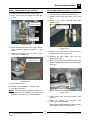
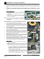
1.
2.
3.
4.
5.
6.
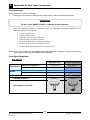
7.
Turn ‘OFF’ the gas supply at the main supply.
Remove the trivets from the top of the appliance, taking note
that the trivets are manufactured with a lip on one edge, the
lip must always be fitted to the outer edge (front and back) of
the cook top.
Remove the burner caps and burner bowls (these are a loose
fit to the manifold) from the top of the gas manifold, taking
care not to damage the thermocouples fitted through the
manifold splash guard.
Remove all the trivet supports from the top of the appliance.
Note the orientation of the trivet supports when removing.
The trivet support front end side rail profiles are different from
the rear end side rail profiles.
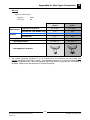
Remove the splash guards covering the burner manifolds by
unscrewing the two allan headed screws. Carefully remove
the splash guards taking care not to damage the
thermocouples protruding through the splash guard.
Unscrew and remove the injectors (½ A/F) from the gas
cocks.
Determine the correct injector sizes for the corresponding gas
from the rating plate.
• For Bench, Cabinet Base and Leg Stand Models, the
Rating Plate is attached to the underside of the right hand
side, front Cook Top lower trim.
•
8.
9.
10.
11.
Notice Lip on
Trivet Edge
Fig 12
Notice Difference
in Edge Profiles
Fig 13
Thermocouple
Splash Guard
Retaining Cap
Screw
For the Refrigerated Base Model, the Rating Plate is
located inside the right hand front panel and can be viewed
through the upper grille. Refer to the ‘Gas Connection’
section and the ‘Dimensions’ section.
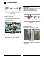
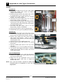
Replace with the correct size injectors. Refer to the ‘Gas
Specifications table’ at the end of this section, for correct
injector sizes.
Refit the splash guards over the gas cocks taking care not to
damage the thermocouples and secure in position with the 2
allan headed screws. (Refer to Fig 14).
Refit the burner caps and burner bowls onto the manifolds
protruding through the splash guards, taking care not to
damage the thermocouple which is close to the manifold.
Take note that the base part of the burner bowl has 2 locating
holes drilled into the base flange, these are to locate the
burner bowl onto the allen headed screws that secure the
splash guard to the gas manifold. (Refer to Fig 15).
Turn on the gas supply at the mains, re-light the burners and
check the flame size on the simmer (LOW) position.
Fig 14
Burner Bowl
Locating Holes
Fig 15
NOTE: The right hand gas control valve supplies the rear burner and the left hand gas control valve
supplies the front burner.
43
Blue Seal Evolution series G51 Gas Cooktops
Revision 1/
© Moffat Ltd, January 2007
A
12.
13.
Appendix A: Gas Type Conversion
Refit all the trivet supports to the top of the appliance. Note the orientation of the trivet support when
re-fitting as the front end side rail profiles are different from the rear end side rail profiles. (See Fig
13).
Refit the trivets to the top of the appliance taking note that the trivets are manufactured with a lip on
one edge, the lip must always be fitted to the outer edge (front and back) of the cook top. (See Fig
12).
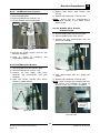
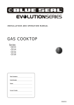
Low Fire Adjustment
a. To adjust the open burner low fire adjustment,
remove the gas control knobs from the front of the
control panel.
b. Adjust the low fire adjustment screw on the open
burner gas control valves to obtain the desired
flame size. (See Fig 16).
NOTE: The “Low Fire Screw” should be sealed with
coloured paint on completion of the low fire
adjustment.
Manifold Test
Point
Low Fire Adjustment Screw
Fig 16
Open Burners ('PF' - Pilot & Flame Failure Option)
1.
2.
3.
4.
5.
6.
Turn ‘OFF’ the gas supply at the main supply.
Remove the trivets from the top of the appliance, taking note
that the trivets are manufactured with a lip on one edge, the lip
must always be fitted to the outer edge (front and back) of the
cook top. (See Fig 12).
Remove the burner caps and burner bowls (these are a loose fit
to the manifold) from the top of the gas manifold, taking care
not to damage the thermocouples and pilot burners fitted
through the manifold splash guard.
Remove all the trivet supports from the top of the appliance.
Note the orientation of the trivet supports when removing. The
trivet support front end side rail profiles are different from the
rear end side rail profiles. (See Fig 13).
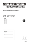
Remove the pilot burner shields from over the pilot burners /
thermocouples by removing the 2 screws securing the pilot
burner shields to the splash guards. (See Fig 18).
Remove the splash guards covering the burner manifolds by
unscrewing the two allan headed screws. Carefully remove the
splash guards taking care not to damage the pilot burner tubes
and thermocouples protruding through the splash guard.
Main Injectors
a. Unscrew and remove the main injectors (½ A/F) from the
gas cocks. (See Fig 19).
b. Replace with the correct size injectors. Refer to the ‘Gas
Specifications table’ at the end of this section and the Rating
Plate for correct injector sizes for the corresponding gas.
•
For Bench, Cabinet Base and Leg Stand Models, the
Rating Plate is attached to the underside of the right
hand side, front Cook Top lower trim.
•
For the Refrigerated Base Model, the Rating Plate is
located inside the right hand front panel and can be
viewed through the upper grille. Refer to the ‘Gas
Connection’ section and the ‘Dimensions’ section.
Fig 17
2 Pilot Burner
Shield Screws
Pilot Burner
Shield
Fig 18
Main Injector
Pilot Injector
Plug
Fig 19
44
Blue Seal Evolution series G51 Gas Cooktops
Revision 1/
© Moffat Ltd, January 2007
Appendix A: Gas Type Conversion
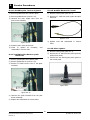
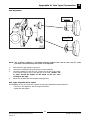
Pilot Injectors
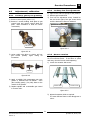
a. Unscrew and remove the Pilot
Injector Plug from the fitting at the
end of the pilot injector tube using
a 11 mm A/F spanner. (Refer to
Fig 20).
b. Using a flat bladed screwdriver,
unscrew and remove the pilot
injector from the pilot injector
housing.
A
Pilot Injector
Housing
Pilot Injector
Plug
Fig 20
NOTE
Take care not to lose the spring fitted in front of the
injector.
c. Remove existing pilot injector and replace with the correct
size pilot injector for the gas type being used. Refer to the
‘Gas Specifications’ table at the end of this section, for
correct pilot injector sizes.
d. Refit the spring and the correct pilot injector to the pilot
injector housing.
e. Screw the pilot injector fully home using a flat blade
screwdriver and refit the pilot injector plug to the pilot
injector housing and tighten in place using a 11 mm A/F
spanner. (Refer to Fig 20).
f. Refit the splash guard over the gas cocks taking care not to
damage the thermocouples and pilot burner tubes. Secure
in position with the 2 allan headed screws. (Note that the
splash guard for 'FP' models has a different cut-outs for
pilot burner tubes. Refer to Fig 22).
g. Refit the pilot burner tube shields over the pilot burner
tubes / thermocouples and secure in place with the 2
securing screws. (Refer to Fig 18).
h. Refit the burner caps and burner bowls onto the manifolds
protruding through the splash guards. Take note that the
base part of the burner bowl has 2 locating holes drilled
into the base flange, these are to locate the burner bowl
onto the allen headed screws that secure the splash guard
to the gas manifold. (Refer to Fig 15).
i. Refit all the trivet supports to the top of the appliance.
Note the orientation of the trivet support when re-fitting as
the front end side rail profiles are different from the rear
end side rail profiles. (Refer to Fig 13).
j. Refit the trivets to the top of the appliance taking note that
the trivets are manufactured with a lip on one edge, the lip
must always be fitted to the outer edge (front and back) of
the cook top. (Refer to Fig 12).
Low Fire Adjustment
a. To adjust the open burner low fire adjustment, remove the
gas control knobs from the front of the control panel.
b. Adjust the low fire adjustment screw on the open burner
gas control valves to obtain the desired flame size. (Refer
to Fig 23).
Cut-Out for Pilot
Burner &
Thermocouple
Fig 21
Pilot Burner
Thermocouple
Shown without Pilot
Burner Shield fitted.
Low Fire Adjustment Screw
Fig 22
Fig 23
NOTE: The “Low Fire Screw” should be sealed with coloured
paint on completion of the low fire adjustment.
45
Blue Seal Evolution series G51 Gas Cooktops
Revision 1/
© Moffat Ltd, January 2007
A
Appendix A: Gas Type Conversion
Griddle
Pilot Burner
a. With the gas supply turned off at the main supply,
remove the griddle plate section by lifting it
straight off the cook top.
b. Remove the gas control heat shield from around
the griddle burner, this is just a push in fit.
c. Disconnect the piezo igniter from the mounting
bracket. (For access purposes).
d. Disconnect the pilot supply tube from the pilot
burner with a 13mm (½") spanner.
e. Remove existing pilot injector and replace with the
correct size for the gas being used. Refer to the
‘Gas Specifications’ table at the end of this section,
for correct injector sizes.
f. Re-connect the pilot supply tube to the pilot
burner with a 13mm (½") spanner.
g. Refit the piezo igniter to the mounting bracket.
h. Repeat Items a) to g) for all griddle pilot burners.
Main Burner
a. Remove the main burner from the burner box by
removing the securing screw at the end of the
burner, this will reveal the main burner injector.
b. Remove and replace the main burner injectors
with correct size injectors. Refer to the ‘Gas
Specifications’ table at the end of this section, for
correct injector sizes.
c. Refit the burner to the griddle burner box.
d. Refit the gas control heat shield to the griddle
burner box.
e. Refit the griddle plate section to the top of the
cook top.
f. Repeat Items (a to (e for all griddle main burners.
g. Turn ‘ON’ the gas supply at the mains, re-light the
griddle burners and check the flame size on the
‘LOW’ flame position.
Gas Control
Heat Shield
Burner
Securing
Screw
Fig 24
Thermocouple
Piezo Igniter
Spring Adjusting
Nut
Pilot Burner
Fig 25
Low Fire Adjustment
a. To adjust the griddle burner ‘LOW’ fire adjustment,
remove the griddle gas control knobs from the
front of the control panel.
b. Adjust the low fire adjustment screw on the
griddle gas control valve only, to obtain the
desired flame size.
NOTE: The “Low Fire Screw” should be sealed with
coloured paint on completion of the low fire
adjustment.
Low Fire Adjustment Screw
Fig 26
46
Blue Seal Evolution series G51 Gas Cooktops
Revision 1/
© Moffat Ltd, January 2007
Appendix A: Gas Type Conversion
A
Gas Regulator
NOTE, Pin rotated
for Natural Gas
NOTE, Pin
rotated for LPG
Fig 27
NOTE: The regulator supplied is convertible between Natural Gas and LP Gas, but it’s outlet
pressure is fixed ex-factory and is NOT to be adjusted.
1.
2.
3.
4.
Ensure that the gas supply is turned off.
Unscrew the hexagonal cap (23mm A/F) from the regulator.
Un-clip the plastic pin from the cap, reverse the pin and re-fit it back
to the cap the correct way for the gas type to be used. (Either ‘LP’
or ‘NAT’ should be visible on the flank of the pin once
re-fitted to the cap).
Screw the cap back into the regulator hand tight only.
Gas Type Identification Label
On completion of the gas conversion, replace the gas type identification label located at:- The rear of the appliance, above the gas connection.
- Beside the rating plate.
47
Blue Seal Evolution series G51 Gas Cooktops
Revision 1/
© Moffat Ltd, January 2007
A
Appendix A: Gas Type Conversion
Commissioning
Before leaving the converted installation;
1.
Check all gas connections for leakages using soapy water or other gas detecting equipment.
WARNING
DO NOT USE A NAKED FLAME
2.
TO CHECK FOR GAS LEAKAGES.
Check the following functions in accordance with the operating instructions specified in the
“Operation” section of this manual.
•
Light the Pilot Burners.
•
Light the Main Burners.
•
Check the Low Fire burner operation.
•
Check the High Fire burner operation.
•
Check the Griddle Burner operation (If Fitted).
•
Ensure that all the controls operate correctly.
•
Ensure that the operating pressure remains correct.
NOTE: If for some reason it is not possible to get the appliance to operate correctly, shut off the
gas supply and contact the supplier of this appliance.
Gas Specifications
- Non-UK Only
Open Burner
Griddle
Natural. Gas
LP Gas (Propane)
Ø 2.45 mm
Ø 1.50 mm
0.30
0.20
Main Burner
Ø 2.10 mm
Ø 1.30 mm
Pilot Burner
0.35
0.23
1.13 - 3.40 kPa
2.75 - 3.40 kPa
0.95 kPa (*)
2.6 kPa (*)
Main Burner Injectors
Pilot Burner ('PF' Option Only)
Supply Pressure
Operating Pressure
Gas Regulator Cap Screw
48
Blue Seal Evolution series G51 Gas Cooktops
Revision 1/
© Moffat Ltd, January 2007
Appendix A: Gas Type Conversion
A
- UK Only
Appliance Classification
Category:
Flue Type:
Open Burner
Griddle
II2H3P.
A1.
Natural. Gas
(G20)
Propane
(G31)
Ø 2.30 mm
Ø 1.40 mm
0.30
0.20
Main Burner
Ø 2.10 mm
Ø 1.30 mm
Pilot Burner
0.35
0.23
20 mbar
37 mbar
9.5 mbar (*)
26 mbar (*)
Main Burner Injectors
Pilot Burner ('PF' Models only)
Supply Pressure
Operating Pressure
Gas Regulator Cap Screw
*
The burner operating pressure is to be measured at the manifold test point with two
burners operating at the ‘High’ setting. The operating pressure is ex-factory set through the
appliance regulator and is not to be adjusted, apart from when carrying out gas conversion, if
required. (Refer to the ‘Gas Conversion’ section for details).
49
Blue Seal Evolution series G51 Gas Cooktops
Revision 1/
© Moffat Ltd, January 2007