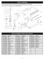
1
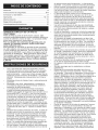
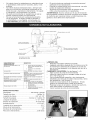
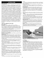
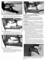
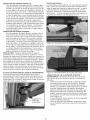
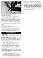
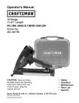
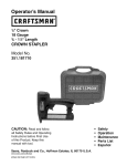
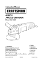
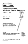
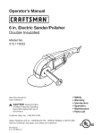
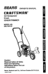
Operation
Manual
CRRFr MRN
MAGNESIUM
t8 Gauge
5/8" - t-1/2"
COMBINATION
Brad
Nailer
NAILER/STAPLER
& 5/8" - t-9/16"
KIT
Stapler
Model 142.18894
CAUTION: Read, understand and
follow all Safety Rules and Operating Instructions in this manual
before using this product.
PRECAUCION:
Lea, comprenda y siga
todas las reglas de seguridad y las instrucciones de operaci6n en este manual
antes de operar este producto
Sears
Brands
Management
www.craftsman.com
Corporation,
Hoffman
Estates,
•
•
Safety
KnowYour
•
•
Operation
Maintenance
•
Troubleshooting
•
•
Espa_ol
Parts List
IL 60179 U.S.A.
Nailer
when the coupling joint is disconnected.
Failure to
use proper coupling could cause accidental discharge, possibly causing injury.
•
Only use air hose that is rated for maximum workWarranty
......................................................................
2
ing pressure of 150 PSI or 150% of the maximum
SafetyInstructions
......................................................
2
system pressure, whichever is greater.
KnowYourNailer.........................................................
3 • Do not pull trigger or depress contact trip while
connecting to the air supply, as the tool may cycle,
Operation
.................................................................
4-6
possibly causing injury.
Maintenance
................................................................
7
•
When loading the tool, do not pull trigger or deTroubleshooting
...........................................................
7
press contact trip. Do not point the tool at yourself
Espadol
..................................................................
8-14
or others. Do not place hand or any part of body in
PartsandIllustrations
List.........................................
15
the fastener discharge area of the tool as accidental
actuation may occur and cause injury.
•
Disconnect tool from air supply before loading or
unloading, performing tool maintenance, clearing
a jammed fastener, leaving work area, moving tool
CRAFTSMAN
ONE YEAR FULL WARRANTY
to another location or handing the tool to another
FOR ONE YEAR from the date of purchase, this
person.
product is warranteed
against any defects in material
•
Use only the size and type of fasteners designated
in the Specifications
list in this manual.
or workmanship.
A defective product will be replaced
•
Do not load the tool until you are ready to use it.
free of charge.
•
Always assume that the tool contains fasteners.
For warranty
coverage
details to obtain free reKeep the tool pointed away from yourself and others
placement,
visit the web site: www.craftsman.com
at
all times. Never engage in horseplay.
Never pull
This ONE YEAR warranty is void if this product is
the trigger unless the contact trip is in contact with
ever used while providing commercial
services or if
the workpiece.
Keep others at a safe distance from
rented to another person. For 90 DAY commercial
the tool while the tool is in operation.
use terms, see listing on Craftsman warranty web
•
Always remove finger from trigger when not driving
page. This warranty gives you specific legal rights,
fasteners to avoid accidental firing. Never carry the
and you may also have other rights which vary from
tool with finger on or under the trigger as accidental
state to state.
actuation may occur and cause injury.
Sears Brands Management
Corp. Hoffman
Es•
Always keep hands and body away from the fastates, IL 60179
tener discharge area when air supply is connected to the tool. Grip tool firmly to maintain control
while allowing tool to recoil away from work surface
as fastener is driven. If contact trip is allowed to
recontact work surface before trigger is released, an
•
Read and follow all safety rules and operating
unwanted fastener may be driven.
instructions in this manual and on warning label of
•
Check operation of the contact trip frequently.
Nevtool before using this tool. Failure to follow warnings
er use the tool if the contact trip, trigger or springs
could result in DEATH or SERIOUS INJURY. Keep
have become inoperable, missing or damaged.
Do
this manual with the tool.
not alter or remove contact trip, trigger or springs.
Keep work area clean and properly lighted.
Never use a tool that is leaking air, has missing or
Keep children, bystanders and visitors at a safe
damaged parts, or requires repair.
distance from work area while operating this tool.
•
Never drive fasteners on top of other fasteners or
Air tool operators and all others in work area MUST
with the tool at too steep an angle. The fasteners
always wear safety goggles complying with the
can ricochet and cause injury. Do not drive fastenUnited States ANSI Z87.1 to prevent eye injury from
ers close to the edge of the work piece. The workfasteners and flying debris when loading, operating
piece is likely to split, allowing the fastener to fly free
and unloading this tool. Everyday eyeglasses have
and cause injury. Do not attempt to drive fasteners
only impact resistant lenses. These are NOT safety
into hard or brittle materials such as concrete, steel
glasses. ANSI Z87.1 safety glasses have permaor tile.
nently attached rigid, hard plastic side shields and
•
Do not overreach. Always place yourself in a firmly
will have "Z87.1" printed or stamped on them.
balanced position when using or handling the tool.
Always wear ear protection. The work area may
Do not attach the hose or tool to your body.
include exposure to excessive noise levels which
•
Do not operate tool without fasteners or damage to
will require necessary ear protection. Some envitool may result.
ronments will require head protection:
use head
•
Do not use tool without safety warning label. If
protection conforming to ANSI Z89.1.
label is missing, damaged or unreadable, contact
Do not alter or modify this tool in any way. Do not
1-800-469-4663
to obtain a new label.
use this tool for any application other than for which
•
Only qualified repair personnel must perform tool
it was designed.
service.
Do not use oxygen, carbon dioxide, high-pressure
•
When servicing a tool, use only identical repair
compressed gas or bottled gases as the power
parts.
source for this tool. The tool will explode and seri•
Store tool out of reach of children and other unous personal injury could result.
trained persons.
Never connect the tool to air pressure which could
WARNING:
Some dust created by using power tools
potentially exceed 200 PSI. Use only clean, dry
contains chemicals known to the State of California to
regulated air within rated range as marked on tool.
cause cancer and birth defects or other reproductive
The tool must have a male, free-flow hose coupling
harm
so that all air pressure is removed from the tool
2
Selectable
Trigger
Rear Exhaust
Male with
Coupling
Muffler
Dust Cap
Tool-free Depth Adjustment
(See Figure 8)
LED Light
Reversible Belt Hook
With Hex Wrench storage
Quick Jam
Magazine
Cover
Release
Latch
Tool Noseplate
No-Mar Tip Storage
(Reverse Side of Tool)
Magazine Cover
FEATURES
BENEFITS
Oil-less
Requires no regular maintenance
and eliminates the risk of oil stains
Design
Tool-free
Depth Adjustment
1. Tool free design for user friendly
2. Control for precise countersinking
LED Light
Offers clearer view in darker areas
Quick Jam Clearance
Tool free mechanism to open the
nose piece to clean the jam
No-Mar
Prevents making
workpiece
Contact
Reversible
Wrench
Trip Pad
Belt Hook with
storage
Selectable
Trigger
Rear Exhaust
with Muffler
Provides
mark on the
convenient
tool carrying
Trigger has two operation settings:
1. Single trigger pull firing
2. Continuous contact trip firing
1. Ultra-quiet
2. Directs air away from the user
during operation
LED LIGHT
•
Requires CR2023 battery (supplied)
•
15 minute automatic shut-off to conserve battery
power in case light is not turned off after tool use.
CHANGING THE BATTERY (See Figure 1 & 2)
•
Open the tool noseplate.
•
Remove the soft protection pad by pulling up on
one of the side tabs. (See Figure 1).
•
Use small screwdriver or other blunt instrument
to push battery up and out of receptacle. (See
Figure 2).
•
Insert new battery into receptacle. Positive side
will face out.
•
Replace the soft protection pad.
•
Close tool noseplate.
SPECIFICATIONS
Capacity ........................................
100 Nails or Staples
Nail Size .......................................................
18 Gauge
Nail Lengths ...................................................
5/8" to 2"
Staple Size ................................ 1/4" Crown, 18 Gauge
Staple Length .........................................
1/2" to 1-9/16"
Operating Pressure ....................................
Air inlet .........................................................
70-120 PSI
1/4" N.P.T.
Tool Length ...........................................................
10.1"
Tool Height ............................................................
ToolWidth ...............................................................
11.2"
2.5"
Tool Weight ......................................................
2.88 Ibs
Figure 1
Figure 2
DESCRIPTION
TheCraftsman18GaugeCombination
Nailerand
Staplerdrivesbradsfrom5/8"to2"longand1/4"
crownstaplesfrom5/8"to 1-1/2"long.Oillessdesign
eliminates
dailyoilingandoilstainsonworkpiece.Die
castmagnesium
bodywithtexturedrubbergripminimizesoperatorfatigue.Largecapacity,
sideloading
magazine
featurespositive,quickactionlatch.Tool
featuresrearexhaust,singlerapid-fire
operation,
adjustable
depthof drivecontrol,rubbernosetip
andstoragecase.Safetyfeaturedisablestooluless
contacttip is pressedagainstworkpiece.
Tapered
nosepiece
providesoperatorwithgreatervisibilityfor
precisefastnerplacement.
Quickreleasenosecover
allowseasyaccesstojammedfasteners.The18
GuageCombination
NailerandStapleris excellent
formolding,furnituremaking,pictureframingand
upholstery.
AIRSUPPLYLINE
See Figure 3
DANGER: Do not use oxygen, carbon dioxide,
high-pressure compressed gas or bottled gases as
the power source for this tool. The tool will explode
and serious personal injury could result.
•
The air tool operates on compressed air at pressures from 70-120 PSI
•
Never connect the tool to air pressure which
could potentially exceed 200 PSI. Use only
clean, dry, regulated air within rate range as
marked on tool.
Air delivery Required: 0.94 SCFM @ 90 PSI. (30
shots per minute).
WARNING:
Keep hands and body away from
discharge area of tool when connecting air supply.
Always disconnect tool from air supply when servicing
or adjusting tool and when tool is not in use.
•
Air operated tools require clean, dry, lubricated
compressed air to ensure top performance, low
maintenance and long life.
•
Dirt and abrasive materials present in all air lines
will damage tool O-rings, valves and cylinders.
•
Moisture will reduce tool performance and life if
not removed from compressed air.
•
The air supply system must be able to provide
air pressure of 70-120 pounds per square inch at
tool.
•
All hoses and pipes in the air supply system must
be clean and free of moisture and foreign particles. Hoses must be rated for maximum working
pressure of 150 PSI or 150% of maximum system
pressure, whichever is greater.
•
Do not mount swivel connector in air supply line.
•
The air pressure should be properly regulated.
•
Different workpiece materials and different
fastener lengths will require different operating
pressure.
•
Be sure all connections in air supply system are
sealed to prevent air loss.
WARNING: This tool is equipped with a male, freeflow coupling for air supply connection. To prevent
accidental discharge and possible injury, NEVER
remove the male coupling to replace with a female
coupling.
To connect tool to air supply:
1. Firmly hold tool by its handle with one hand. Be
sure to point tool away from you and others in
the area.
2.
With other hand, insert female coupling of air
hose over male coupling of tool until hose coupling is firmly seated.
CAUTION: When connecting or disconnecting air
hose, air pressure may cause the the hose coupling
to kick back if the hose coupling is not firmly seated
on tool coupling.
NOTE: When hose is disconnected from tool, snap
the dust cap over the tip of the tool male coupling.
Figure 3-Air Supply Line
LOADING
See Figures 4-7 (Pages 4 & 5)
WARNING: Disconnect tool from air supply. Do not
load tool until you are ready to use it. Do not pull trigger or depress contact trip while loading tool. Make
sure that the tool noseplate is securely closed before
loading fasteners. Always load with nose of tool pointing away from you and others. Always wear safety
goggles that comply with United States ANSI Z87.1.
•
Depress the magazine cover release latch and
slide magazine cover open. (See Figure 4)
Figure 4-Open Magazine Cover
NAILING
ANDSTAPLING
OPERATION
SeeFigures8-10(Pages5 &6)
WARNING:Readandfollowallsafetyrulesand
operatinginstructions
inthismanualandonwarning
labeloftoolbeforeusingtool.Keepthismanualwith
thetool.
WARNING:Donotusethistoolwithoutsafetywarninglabel.If labelis missing,damaged
or unreadable,
contact1-800-469-4663
toobtaina newlabel.
WARNING:Neveroperatetoolunlesscontacttrip
is incontactwithworkpiece.Donotoperatetool
withoutfastenersor damagetotoolmayresult.Neverfirefastenersintotheairbecausefastenersmay
injureoperatoror othersanddamagetotoolmay
result.
• Perform"SafetyMechanism
Check"asdescribed
intheMaintenance
section(SeePage7) priorto
firstuseoftoolandona dailybasisthereafter.
• Thetoolisequippedwitha rotatingswitchthat
canbesetto rapid-fireor single-fire
mode(See
Figure8). Whentheswitchis settosingle-fire
mode,thetoolwill notdrivea secondfastener
untilthetriggerisfullyreleasedandpulledagain.
• Whentheswitchis rotatedto rapid-firemode,the
toolcandrivefastenerscontinuously.
Afastener
willbefiredeachtimethecontacttripis pressed
againsttheworkpiece,
aslongasthetriggeris
maintained
inthe pulledposition.
LoadNails:Placenailstripso thatthechisel
pointsrestonthebottomofthemagazine.
(See
Figure5)
Figure5-LoadingNails
* LoadingStaples:Positionstaplessothatthe
staplestripstraddlesandrestsontheinnerwall
ofthemagazine.
(SeeFigure6).
Figure6-LoadingStaples
* Slidemagazine
coverforwardovermagazine
until
latchsnapsintoplace,lockingmagazine
cover.
(SeeFigure7).
Figure8-PushandRotateSwitch(pushingfromthe
backside)
toSelectOperationMode
SINGLE-FIRE
OPERATION:
* Forsingle-fire
operation,
pushintheroundside
oftheredspringloadedtriggerswitch,androtate
theteardropshapedsidesothatit dropsintothe
switchrecessfacingtheonenailicon.Theairtool
is equipped
witha contacttripsafetymechanism
thatdisablestoolsunlesscontacttripis pushed
againstwork. Todrivea fastener,holdtoolfirmly
andpresscontacttriponworkpiece
wherefastener isto beapplied.Pulltriggertodrivefastener
intoworkpiece.Tofirea secondfastenerliftthe
toolfromtheworkpiece,
releasethetriggerand
thenrepeattheabovesequence.
RAPID-FIRE
OPERATION:
* Forrapid-fireoperation,
pushintheroundsideof
theredspringloadedtriggerswitch,androtate
theteardropshapedsidesothatit dropsintothe
switch
Figure7-CloseMagazine
5
•
recessfacingthethreenailicon.Holdthetrigger
depressed
andpushcontacttripagainstworkpiece.Afastenerwillbedriveneachtimethe
contacttripis pushedagainsttheworkpiece.
This
operatingprocedure
providesrapid-firefastener
driving.Neveroperatetoolunlesscontacttripis
in contactwithworkpiece.
CAUTION:
Allairpowerfasteningtoolsrecoilwhen
operated.Thisrecoiliscausedbyrapiddrivingof
thefastener.Toolmaybouncefromrecoilcausinga
secondunwanted
fastenerto bedriven.Reducetool
bouncebyholdingtoolfirmlyin handandpressing
toolgentlyagainstworkpiece.Letthetooldothe
work.Thiswillallowrecoiloftoolto bouncetoolaway
fromworkpiece
preventing
thedrivingofsecond
fastener.
TOOL-FREE
DEPTHADJUSTMENT
Thecontacttrip maybeadjustedupor downtovary
the depthofthefastenerintheworkpiece.Toadjust,
rotatedepthcontrolwheel(SeeFigure9)to raiseor
lowercontacttriptodesiredsetting.
Figure11-Storing
No-MarTip
CLEARING
AJAMMEDFASTENER
WARNING:
Disconnect
toolfromairsupplybefore
attempting
to clearjammedfasteners.
• Depressthemagazine
coverreleaselatchand
slidethe magazine
coveropen.Removeanyremainingfastenersfromthe magazine.
NOTICE:
Fasteners
areunderspringpressureandmay
dislodgefromthemagazine.
• Graspnosecoveronbothsidesandpulloutward
untilpindisengages
fromlatch,thenpullupward
sothatfastenerguideplateswingsawayfrom
magazine(SeeFigure12).
• If necessary,
uselongnosepliersto removethe
jammedfastener.
• Closefastenerguideplate,hookpinintolatch
andsnapnoseplate
closed.
Figure9-SettingDepthControl
NO-MARTIP
Thetoolis equipped
witha no-martipthatprevents
marringoffinishedsurfacesbythecontacttripduring
normaloperation.Tipcanberemovedandstored
onthestoragesleevelocatedontheendcoverof
the magazine.
Hexwrenchis alsostoredonthebelt
hook.(SeeFigures10& 11)
Figure12-Clearing
a JammedFastener
OPERATING
PRESSURE
• Useonlyenoughairpressureto performtheoperation.Air pressureinexcessofthatwhichis requiredwill maketheoperationinefficientandmay
causepremature
wearor damagetothetool.
• Determine
minimumair pressurerequiredby
drivingsometestfastenersintotheworkpiece.
Setairpressureso thattestfastenersaredriven
downflushwiththeworksurface.Fasteners
driventoodeepmaydamageworkpiece.
Figure10-Storing
HexWrench
COLDWEATHER
OPERATION
CAUTION:Donotstorein coldenvironment.
Frost
or icecouldforminsidetoolaffectingoperationand
damagingtool.Usea coldtemperature
lubricant,
suchasethylene glycol, when operating tool in freez-
SAFETY MECHANISM CHECK
inspect contact trip safety mechanism daily for proper
operation. Do not operate tool if mechanism is not
operating properly.
With the red trigger switch in the rapid-fire mode,
perform the following procedures to test safety mechanism:
•
Leave trigger untouched while pushing contact
trip into workpiece. Tool must not fire.
•
Pull Trigger while contact trip is clear of work and
pointed away from operator and others, Tool
must not fire.
•
Depress and hold trigger. Push contact trip
against work where fastener as needed. The tool
should drive only one fastener is needed. The
tool should drive only one fastener each time the
contact trip is pushed against workpiece.
If contact trip mechanism does not operate properly, immediately discontinue tool operation and
take the tool to a qualified service dealer for possible repair. Reference the parts list in this manual
for correct replacement parts,
ing temperatures.
LUBRiCATiON
This is an oilless tool. No lubrication is necessary.
BELT HOOK REVERSAL
To reattach belt hook to other side of tool, use the
supplied hex wrench stored in belt hook.
1. insert hex wrench into hex screw on opposite
side of tool.
2. Loosen and remove both screw and hook.
3. Reverse sides of screw and hook and tighten
hook securely into place.
SYMPTOM
Trigger
air
cap leaks
POSSIBLE
CAUSE(S)
CORRECTIVE
1.
2.
O-ring damaged
Valve stem, seal or O-rings
1.
ACTION
1.
2.
Check and replace
Check and replace
Cap bolts loose
1.
Tighten
2.
Damaged
gasket
2.
3.
Damaged
O-ring
1.
2.
Damaged
Damaged
cylinder
bumper
damaged
damaged
damaged
O-ring
stem, seal or O-
Check and replace
damaged
gasket
3.
Check and replace
damaged
O-ring
1.
2.
Check and replace
Check and replace
damaged
damaged
O-ring
bumper
guide
rings
Cap leaks air
Nose leaks air
O-ring
bolts
3.
Ram guide damaged
3.
Check and replace
Tool will not
1.
Insufficient
1.
Check air supply
operate
2.
Damaged
seal
2.
Replace
damaged
3.
Replace
damage
air supply
or worn head valve O-ring or
or worn O-ring
or seal
spring
3.
4.
Damaged head valve spring
Head valve binding in cap
4.
Clean and grease
Tool operates
slowly or loses
1.
2.
Damaged
Damaged
1.
2.
Check and replace
Check and replace
power
3.
Damaged
4.
Build-up
on ram
5.
Cylinder
properly
not sealed
6.
Insufficient
7.
Head valve poorly lubricated
Tool skips fasteners
or inconsistent
1.
Worn or damaged
2.
Build-up
operation
3.
Insufficient
4.
Damaged
5.
6.
7.
Damaged magazine springs
Magazine-nose
bolts loose
Fasteners too short
6.
Align nose with magazine
8.
9.
Damaged fasteners
Incorrect fastener size
7.
Use only the size and type of fasteners
10.
11.
Cap leaks
Damaged trigger valve seal and O-
8.
9.
head valve spring
or worn O-rings
trigger assembly
on bumper
air supply
3.
Check and replace
Clean piston/ram
5.
6.
Disassemble
cylinder
Check air supply
Disassemble
assemble
bumper
Clean and grease
of nose cover
3.
Check air supply
4.
5.
Check and replace
Check and replace
designated
13.
Dirty magazine
14.
Damaged
ram
and assemble
head valve,
Check and replace
properly
clean, grease and
bumper
piston/ram
assembly
and inside
O-ring
springs
and tighten bolts
in the Specifications
list in this manual
Discard damaged fasteners
Use only the size and type of fasteners
designated
Bent or damaged
trigger assembly
properly
2.
rings
12.
spring
or worn O-rings
assembly
1.
air supply
or worn piston O-ring
damaged
damaged
4.
7.
on ram or nose
cap and head valve
10. Tighten
in the Specifications
list in this manual
cap bolts. Check and replace
damaged
gasket
or worn magazine
7
11.
12.
Check and replace
Check and replace
13.
Clean magazine
lubricant.
14.
Check and replace
damaged
damaged
and lubricate
magazine
seal and O-rings
piston/ram assembly
with a dry, film
•
Garantia
......................................................................
Instrucciones
Conozca
Operaci6n
de seguridad
su clavadora
......................................
................................................
.............................................................
Mantenimiento
...........................................................
Diagn6sticodeavedas
Listadeparteseilustraciones
8
8-9
...............................................
......................................
•
9
10-13
13
14
15
GARANTiA COMPLETA DE UN AI_O DE
CRAFTSMAN
POR UN ANO a partir de la fecha de compra, este
producto estara garantizado contra cualquier defecto en
cuanto al material y mano de obra. Un producto defectuoso sera repuesto sin costo alguno.
Por los detalles de cobertura
de garantia para asi
obtener un repuesto gratuito,
visite el sitio web:
www.craftsman.com
Esta garantia de UN AI_O se anulara si este producto
se usara alguna vez para brindar servicios comerciales
o si se rentara a otra persona. Por los terminos de uso
comercial de 90 DiAS, vea la lista en ia pagina web de
garantias de Craftsman.
Esta garantfa le brinda derechos legales especificos y usted puede contar con derechos adicionales los cuales varian de estado a estado.
Sears Brands Management
Corp. Hoffman Estates,
IL 60179
•
•
•
•
•
•
•
•
o
o
Lea y siga todas tas reglas de seguridad e instrucclones de operaci6n en este manual y en ta etiqueta
de advertencia de la herramienta antes de emplear
esta herramienta.
Hacer caso omiso al seguir tas advertencias podria ocasionar la MUERTE o LESIONES
SERIAS. Mantenga este manual junto con ta herramienta.
Mantenga et area de trabajo limpio y adecuadamente
ituminado.
Mantenga a los nifios, espectadores y visitantes a
una distancia segura det area de trabajo durante la
operaci6n de esta herramienta.
Los operadores de tas herramientas neumaticas
y todas tas dem&s personas en et area de trabajo
DEBEN usar gogtes de seguridad que cumplan con la
norma ANSI Z87.1 de los E.U. con el fin de prevenir
lesiones de los ojos provenientes de los sujetadores
y escombros volantes al momento de cargar, operar y
descargar esta herramienta. Los tentes de uso diario
cuentan solo con tentes de resistencia al impacto.
Estos NO son lentes de seguridad. Los tentes de seguridad ANSI Z87.1 cuentan con protectores laterales
rigidos de plastico duro permanentemente sujetados
y aparecera et selto "Z87.1" impreso o seltado sobre
ellos.
Siempre lleve puesto protecci6n de oidos. El area de
trabajo puede incluir la exposici6n a nivetes sonoros
excesivos la cual requerira una protecci6n de oidos
adecuada. Atgunos ambientes requeriran et uso de
protecci6n de la cabeza: use protecci6n de la cabeza
que conforme a la norma ANSI Z89.1.
No altere ni modifique esta herramienta de ninguna
forma. No ocupe esta herramienta para ninguna aplicaci6n que no sea la para la cual fue disefiada.
No use oxigeno, di6xido de carbono, gas comprimido
de alta presi6n ni gases embotettadas como la fuente
•
•
•
•
•
de potencia para esta herramienta. La herramienta
explotara y se podrian ocasionar lesiones personales.
Nunca conecte ta herramienta a una presi6n de aire
la que podria potencialmente exceder unas 200 PSI.
Use s61o aire limpio y seco dentro det tango ctasificado
segQn este marcado en ta herramienta.
La herramienta debe contar con un acoplamiento
macho de flujo libre de ta manguera con et fin de se
extraiga toda ta presi6n de aire de ta herramienta
cuando la junta del acoplamiento este desconectado.
Hacer caso omiso al usar un acoplamiento adecuado
podria ocasionar una descarga accidental, potencialmente ocasionando tesiones.
Use s61o una manguera de aire que sea ctasificada
para una maxima presi6n de trabajo de unos 150 PSI
o et 150% de la maxima presi6n det sistema, cualquiera que sea mayor.
No jale et disparador ni presione ta traba de seguridad
mientras que se este conectando al suministro de aire,
dado que la herramienta pueda ciclar, potencialmente
ocasionando tesiones.
At momento de cargar la herramienta, no jale et disparador ni presione la traba de seguridad. No apunte
la herramienta a uno mismo ni a otros. No coloque ta
mano ni ninguna otra parte det cuerpo en et area de
descarga det sujetador de la herramienta, ya que se
podria ocasionar una acci6n accidental y asi ocasionar
lesiones.
Desconecte la herramienta det suministro de aire antes
de cargar o descargar la carga, antes de la realizaci6n
de mantenimiento a la herramienta, al momento de
librar un sujetador atorado, al salirse det area de trabajo, cambiar la herramienta a otra ubicaci6n o dar la
herramienta a otra persona.
Use s6to et tamafio y tipo de sujetadores designados
en la lista de especificaciones de este manual.
No cargue la herramienta hasta que uno este listo para
usarta.
Siempre suponga que los sujetadores contienen
sujetadores.
Mantenga la herramienta apuntada lejos de uno
mismo y de otros en todo momento. Nunca metase
en tonterias. Nunca jale et disparador al menos que la
traba de seguridad este en contacto con ta pieza de
trabajo. Mantenga a otros a una distancia segura de la
herramienta, mientras que esta este en operaci6n.
Siempre quite et dedo det disparador cuando no se
esta conduciendo los sujetadores con et fin de evitar et
disparo accidental. Nunca tleve la herramienta con un
dedo o debajo det disparador, ya que se podria ocasionar una acci6n accidental y asi ocasionar lesiones.
Siempre mantenga las manos y et cuerpo tejos del
girea de descarga det sujetador cuando et suministro de aire este conectado a la herramienta. Agarre
la herramienta firmemente para mantener control al
mismo tiempo que se permita que la herramienta
rebote de la superficie det trabajo durante et disparo
det sujetador. Si se permite que ta traba de seguridad
tenga contacto de nuevo con la superficie de trabajo
antes de que se tibere el disparador, se puede disparar
un sujetador indeseado.
Revise ta operaci6n de la traba de seguridad frecuentemente. Nunca use la herramienta si la traba de
seguridad, et disparador o los resortes se hayan vuetto
inoperabtes, si haya faltantes de los mismos o si esten
dafiados.
No modifique ni extraiga ta traba de seguridad, el disparador ni los resortes. Nunca use ninguna
herramienta que tenga alguna fuga de aire, que cuenta
con partes faltantes o que requiera reparaciones.
Nunca conduzca los sujetadores encima de otros
sujetadores o dentro de la herramienta a un anguto demasiado inclinado. Los sujetadores pueden rebotarse
y ocasionar lesiones. No conduzca los sujetadores
cerca det borde de la pieza de trabajo. Es probable
que se divida la pieza de trabajo, permitiendo que et
sujetador vueta libremente y asi ocasionara lesiones.
•
•
•
•
Nointente
ctavarlossujetadores
enmateriates
duros
niquebradizos,
talescomoetconcreto,
acero,
nilos
azulejos.
Nointente
atcanzar
demasiado
tejos.Siempre
p6ngaseenunaposici6n
firmemente
equitibrada
atmomento
deusary maniobrar
taherramienta.
Nosujete
lamanguera
nilaherramienta
asucuerpo.
Nooperelaherramienta
sinsujetadores
yaquese
podrian
ocasionar
da_osataherramienta.
Nouselaherramienta
sinlaetiqueta
deadvertenciadeseguridad.
Sitlegara
afaltartaetiqueta,
o
siestada_ada,
o siesitegible,
comuniquese
con
1-800-469-4663
paraobtener
unanuevaetiqueta.
•
Etservicio
debesetrealizado
potpartedepersonal
calificado
enlasreparaciones.
• Durante
etmantenimiento
delaherramienta,
uses61o
partes
dereparaci6n
identicas.
• Almacene
laherramienta
fueradetalcance
delos
niSos
y deotraspersonas
nocapacitadas.
ADVERTENClA:
Etpolvocreado
potelusodeherramientasneumatcias
contienen
quimicos
conocidos
enetestado
deCalifornia
potocasionar
cancer
y matformaciones
congenitas
u otrosdaSos
delareproducci6n
Disparador
seleccionable
iiii
Ajuste
libre
de profundidad
Gancho de cinturon
con almacenamiento
reversible
de llaves
Liberacion rapida
de atoramiento
Almohadilla
de la traba/_
de seguridad
CARACTERiSTICAS
SOBRESALIENTES
Ajuste de profundidad tibre de ta
herramienta
LSmpara DEL
Liberaci6n rapida de atoramiento
Atmohadilta de elemeeto de contacto
anti-rayas
Gancho de cintur6n reversible con
atmaceeamiento de ttaves
Disparador seteccionable
Escape trasero con mofle
anti-rayas
LAMPARA DEL
•
Requiere una bateria CR2023 (provista)
•
Apagado automatico despues de 15 minutos con el fin
de conservar la potencia de ta bateria en el caso de
que no se haya apagado la luz despues det uso de la
herramienta.
CAMBIANDO LA BATERiA (Ver tas figuras 1 y 2)
•
Abra ta placa de punta de la herramienta
•
Afloje los cuatro tornitlos y extraiga la tapa de la bateria. (Vet la figura 1).
•
Use un destomitlador pequeSo u otto instrumento
desafilado para empujar ta bateria hacia arriba y fuera
det receptaculo. (Ver ta figura 2).
•
Inserte la nueva bateria en el receptaculo. Et tado
positivo se orientara hacia ta tapa de ta bated&
•
Reponga la tapa de la bated& Apriete los cuatro tornitlos para sujetar ta cubierta en su tugar
•
Cierre la placa de punta de la herramienta.
BENEFIClOS
1. Dise_o tibre de herramienta
para et ajuste amigabIe de los
usuarios.
2. Control por un avettanado
preciso
Ofrece una vista mas clara ee areas
oscuras
Mecanismo libre de herramienta para et
despeje r_pido de atoramiento de ta
nariz de la herramienta.
Prevenci6n de marcas en ta pieza de
trabajo
Brinda una carga convenieete de la
herramienta
Et disparador cuenta con dos ajustes:
1. Disparo sencitto por disparador
2. Et disparo continuo por la traba
de seguridad
1. Super sitencioso.
2. Dirige el aire lejos det usuario
durante ta operaci6n
ESPECIFICACIONES
Capacidad ..............................................
100 ctavos o grapas
TamaSo de ctavo ...................................................
Calibre 18
Longitud de ctavos ............................................. 5/8" a 2-1/8"
TamaSo de grapas ............................ Corona ¼", Calibre 18
Longitud de grapas ...........................................
½" a 1- 9/16"
Presi6n de operaci6n ......................................... 70 a120 PSI
Entrada de aire ......................................................
1/4" N.RT.
Longitud de la herramienta ............................................
10.1"
Altura de la herramienta .................................................
11.2"
Anchura de la herramienta ...............................................
2.5"
Peso de la herramienta ......................................... 2.88 libras
Figura 1
9
Figura 2
mente.
• Los varios materiales de ta pieza de trabajo y tas larguras
de los sujetadores diferentes requeriran una presi6n de aire
diferente cada uno.
• AsegOrese que todas las conexiones en et sistema de
suministro de aire esten seltadas con et fin de prevenir una
perdida de aire.
ADVERTENClA:
Esta herramienta esta equipada con un
acoplamiento macho de circulaci6n tibre para ta conexi6n
det suministro de aire. Con et fin de prevenir una descarga accidental y lesiones potenciales, NUNCA extraiga et
acoplamiento macho para reponerto con un acoplamiento
hembra.
DI=SCRIPCl6N
La ctavadora de espigas y engrapadora de combinaci6n
de calibre 18 de Craftsman ctava espigas de 5/8" a 2" de
largo y grapas de corona ¼" entre 5/8" y 1-1/2" de largo.
Et disefio libre de aceite etimina la lubricaci6n diaria y tas
manchas de aceite en la pieza de trabajo. Et cuerpo de
magnesio fundido a presi6n con agarre de hule texturizado
minimiza la fatiga det operador. Et dep6sito alimentador
de gran capacidad y de carga pot extremo se caracteriza
pot un pestitlo positivo de acci6n rapida. La herramienta se
caracteriza pot una operaci6n sencitta de disparo rapido
con escape trasero, un control ajustabte de profundidad de
disparo, una punta de hule y un estuche de almacenamiento. El etemento de seguridad desactiva ta herramienta al
menos que la traba de seguridad este presionada contra la
pieza de trabajo. Et puente nasal conificado de la herramienta le brinda al operador una mayor visibitidad para la
colocaci6n precisa det sujetador. La rigidez de la nariz
de la herramienta disminuye los atoramientos. La cubierta
de nariz de tiberaci6n rapida permite una facit acceso a
los sujetadores atorados. La clavadora y engrapadora de
combinaci6n de calibre 18 es excetente para et trabajo
de molduras, la ebanisteria, los armazones de fotos y et
tapizado.
Para conectar la linea de suministro
de aire de la herramienta:
1. Con una mano, sostenga ta herramienta firmemente pot
su mango. AsegOrese de apuntar ta herramienta tejos de
usted y de otras personas en et area.
2. Con ta otra mano, inserte et acoplamiento hembra de ta
manguera de aire sobre et acoptamiento macho de la herramienta hasta que et acoplamiento de ta manguera este
firmemente asentado.
PRECAUClON: At momento de conectar o desconectar la
manguera de aire, la presi6n de aire puede ocasionar et
rebote det acoplamiento de manguera si el acoptamiento
de manguera no este asentado en et acoplamiento de ta
herramienta.
NOTA: Cuando la manguera esta desconectada de la
herramienta, abroche et guardapolvo sobre la punta det
acoplamiento macho de la herramienta.
LiNEA DE SUMINISTRO DE AIRE
(Ver la figura 3)
PELIGRO: No use oxigeno, di6xido al carbono,
aire comprimido de alta presi6n ni gases embotettados
como la fuente de potencia de esta herramienta. La herramienta explotara y se podrian ocasionar lesiones serias.
• La herramienta neumatica opera con aire comprimido a
una presi6n de aire de 70 a120 PSI
• Nunca conecte ta herramienta a una presi6n de aire la
cual podria potencialmente exceder las 200 PSI. Use s61o
aire regulado timpio y seco dentro det rango segOn sea
indicado en ta herramienta.
Entrega de aire requerida: 0.94 SCFM a unos 90 PSI (30
golpes pot minuto).
AVERTENClA:
Mantenga las manos y cuerpo tejos det
area de descarga de la herramienta al momento de conectar et suministro de aire. Siempre desconecte ta herramienta det suministro de aire durante et mantenimiento o
durante et ajuste de herramienta y cuando la herramienta
no esta en uso.
• Las herramientas neumaticas requieren aire comprimido
limpio, seco y lubricado con et fin de asegurar un rendimiento 6ptimo, un minimo mantenimiento y una vida t_tit
larga de la herramienta.
• La suciedad y materiales abrasivos presentes en todas
la lineas de aire dafiaran los anitlos en O, la valvulas o
citindros.
•La humedad reducira et rendimiento de ta herramienta y
de la vida Qtit de ta herramienta siesta no se extraiga det
aire comprimido.
• El sistema de suministro de aire debe brindar una presi6n
de aire de 70 a 120 tibras pot pulgada cuadrado en la
herramienta.
• Todas las mangueras y tubos en et sistema de suministro de aire deben de estar limpios y tibres de humedad y
particulas foraneos. Las mangueras deben estar ctasificadas para una maxima presi6n de trabajo de 150 PSI o
un 150% de maxima presi6n det sistema, cualquiera viene
siendo mayor.
• No monte et conectador giratorio en la linea de suministro
de aire.
• La presi6n de aire debe de estar regulada adecuada-
Figura 3 - La linea de suministro de aire
LA CARGA
Vet las figuras 4 a 7
ADVERTENClA:
Desconecte la herramienta det suministro de aire. No cargue la herramienta hasta que este listo
para usarta. No jale et disparador ni presione ta traba de
seguridad al momento de cargar la herramienta. AsegOrese
que la placa de ta punta este seguramente cerrada antes
de cargar los sujetadores. Siempre cargue con ta punta
de la herramienta apuntandose lejos de usted y de otras
personas. Siempre lleve puesto gogles de seguridad que
cumplan con ta norma ANSI Z87.1 de los E.U.
• Presione et pestillo de liberaci6n de ta cubierta det dep6sito alimentador y destice para abrir la cubierta det dep6sito
alimentador (Vet la figura 4)
10
Figura 4- Abra la cubierta det dep6sito alimentador
•
Figura 7- Cierre el dep6sito alimentador
OPERAClON DE CLAVADO Y DE ENGRAPE
Carga de ctavos: Coloque ta tira de ctavos para que
los puntos det cincel reposen sobre ta parte inferior det
dep6sito alimentador (Vet la figura 5)
Vet tas figuras 8 a 10
ADVERTENClA:
Lea y comprenda todas las reglas de
seguridad e instrucciones de operaci6n en este manual
yen la etiqueta de advertencia de ta herramienta antes
de usar esta herramienta. Mantenga este manual con la
herramienta.
ADVERTENClA:
No use esta herramienta sin la etiqueta
de advertencia de seguridad. Si ta etiqueta es fattante,
esta dafiada o es itegible, comuniquese al 1-800-469-4663
para obtener una nueva etiqueta.
ADVERTENClA:
Nunca opere esta herramienta al menos
que la traba de seguridad de contacto este en contacto con
la pieza de trabajo. No opere la herramienta sin sujetadores ya que se podrian ocasionar dafios a la herramienta.
Nunca dispare sujetadores en et aire pot que los sujetadores podrian tesionar al operador o a otros y se podrian
ocasionar daSos a la herramienta.
°
Realice la "Verificacion det mecanismo de seguridad"
segQn sea descrita en ta secci6n de mantenimiento
(ver ta pagina 13) previo al primer uso de la herramienta y, posteriormente, de forma diaria
°
La herramienta viene equipada con un interruptor
giratorio, el cual puede ajustarse al modo de disparo
rapido o de un s6to disparo (Vet la figura 8). Cuando
el interruptor este ajustado at modo de un s61o disparo,
la herramienta no conducira un segundo sujetador
hasta que et gatitlo este completamente liberado y jalado de nuevo.
°
Cuando el interruptor este girado hasta et modo de
disparo rapido, ta herramienta puede pegar sujetadores de forma continua. Un sujetador se disparara cada
vez que la traba de seguridad este presionada contra
la pieza de trabajo, siempre y cuando et disparador se
mantenga en la posici6n de jalar.
Figura 5- Carga de clavos
•
Cargando Ias grapas: Cotoque Ias grapas para que Ia
tira de grapas se extienda sobre y repose en el muro
interior deI dep6sito alimentador (Ver la figura 6)
Figura 6- Carga de grapas
°
Destice la cubierta det dep6sito alimentador hacia
adetante sobre et dep6sito alimentador hasta que et
pestitlo de abroche en lugar, bloqueando la cubierta det
dep6sito alimentador (Vet la figura 7)
Figura 8- Interruptor de Empuje y Rotaci6n (empujando
desde la parte posterior) para seteccionar et modo de
operaci6n
11
OPERAClON
DEDBPARO
SENClLLO:
PUNTA ANTI-RAYAS
La herramienta viene equipada con una punta anti-rayas ta
que previene que se rayen tas superficies acabadas por ta
traba de seguridad durante ta operaci6n normal, La punta
puede extraerse y almacenarse en ta manga de almacenamiento ubicada en et cubierta det extremo det dep6sito
alimentador,
La tlave hexagonal tambien se almacena en
et gancho det cintur6n, (Ver las figuras 10 y 11)
*
Para ta operaci6n de disparo sencilto, empuje et lado
redondo det interruptor de disparo rojo conducido por
resorte y gire et lado en forma de tagrima con et fin de
que se caiga en et receso del interruptor orientado hacia et icono de un solo ctavo. La herramienta neumatica viene equipada con un mecanismo de seguridad de
la traba de seguridad et cual deshabilita tas herramientas al menos que ta traba de seguridad este empujada
contra ta pieza de trabajo. Para conducir un sujetador,
sostenga la herramienta firmemente y presione la
traba de seguridad sobre ta pieza de trabajo donde et
sujetador sera aplicado. Jate et disparador para conducir el sujetador en ta pieza de trabajo. Para disparar
un segundo sujetador, levante la herramienta de la
pieza de trabajo, tibere et disparador y luego repita la
secuencia anterior.
OPERAClON DE RAPIDO DISPARO:
*
Para la operaci6n de rapido disparo, empuje sobre et
lado redondo det interruptor det disparador rojo conducido por resorte y gire el lado en forma de tagrima
para que caiga en et receso det interruptor orientado
hacia et icono de tres ctavos. Sostenga presionado
el disparador y empuje la traba de seguridad contra la
pieza de trabajo. Se disparara un sujetador cada vez
que la traba de seguridad este empujada contra la pieza de trabajo. Este procedimiento de operaci6n brinda
un disparo rapido de los sujetadores. Nunca opere
esta herramienta al menos que la traba de seguridad
este en contacto con ta pieza de trabajo.
PRECAUCl6N:
Todas las herramientas de sujeci6n
neumatica dan un culetazo durante su operaci6n.
Dicho
culetazo se ocasiona por et disparo rapido del sujetador. La
herramienta puede rebotarse por et culetazo ocasionando
asi et disparo indeseado de un segundo sujetador. Reduzca el rebote de ta herramienta al sostener la herramienta
firmemente en ta mano y al presionar la herramienta suavemente contra la pieza de trabajo. Deje que ta herramienta
haga et trabajo. Esto permitira que et culetazo de la herramienta rebote ta herramienta tejos de la pieza de trabajo
asi previniendo et disparo de un segundo sujetador.
AJUSTE DE PROFUNDIDAD LIBRE DE HERRAMIENTA
La traba de seguridad puede ajustarse hacia arriba o
hacia abajo para variar la profundidad det sujetador en la
pieza de trabajo. Para ajustar, gire la rueda de control de
profundidad (Vet la figura 9) paya elevar o bajar la traba de
seguridad hasta et ajuste deseado.
Figura 10- Almacenamiento
de ltave hexagonal
Figura 11-Almacenamiento
de ta punta anti-rayas
LIBERACION DE UN SUJETADOR ATORADO
ADVERTENCIA: Desconecte ta herramienta del suministro de aire antes de intentar de tiberar los sujetadores
atorados.
*
Presiona et bot6n det empujador y jale el empujador
hacia atras hasta que se abra la pestitlo. Extraiga
los sujetadores restantes det dep6sito alimentador.
AVISO: Los sujetadores estan bajo presi6n de resorte
y pueden desprenderse det dep6sito alimentador.
*
Agarre la cubierta de ta punta de los dos lados y jale
hacia afuera hasta que et pasador se desencaje det
pestitlo, luego jale hacia arriba para que la ptaca guia
det sujetador se oscite lejos det dep6sito alimentador
(Ver la figura 12).
*
Si sea necesario, use los alicates de punta larga para
extraer et sujetador atorado.
*
Cierre la placa guia det sujetador, enganche el pasador en ta pestitto y abroche la placa de la punta para
cerrarla.
Figura 9- Ajustando el control de profundidad
12
Presione y jale et disparador. Empuje la traba de
seguridad contra ta pieza de trabajo donde se requiera
un sujetador. La herramienta debera ctavar s6to un
sujetador cada vez que la traba de seguridad este empujado contra la pieza de trabajo. Si el mecanismo
de la traba de seguridad no opera de forma adeeuada, discontinue inmediatamente la operation de
la herramienta y Ileve la herramienta a una agencia
de servicio calificado por reparaciones potenciales. Consulte la lista de partes en este manual por las
partes de repuesto correctas.
Figura 12- Liberacidn de un sujetador atorado
PRESION DE OPERACION
•Use s61o ta suficiente presidn de aire para realizar ta
operaci6n. La presidn de aire en exceso de ta requerida
volvera ineficiente la operaci6n y podria ocasionar et desgaste prematuro o dafios a la herramienta.
•Determine ta minima presi6n de aire requerida al disparar
algunos sujetadores de prueba en ta pieza de trabajo.
Ajuste ta presi6n de aire para que los sujetadores de prueba esten conducidos hacia abajo al ras con la superficie
de trabajo. Los sujetadores los que se disparan demasiado profundamente en la pieza pueden dafiar la pieza de
trabajo.
OPERACION EN TIEMPO FRiO
PRECAUCION: No almacene en ambientes frios. Se
podria formar escarcha o hieto adentro de ta herramienta, asi afectando ta operaci6n y ocasionando dafios a ta
herramienta. En temperaturas de congetamiento, use un
lubricante para temperaturas frias, tales como et etiteno
gticol, durante la operaci6n de la herramienta.
LUBRICACION
Esta es una herramienta libre de aceite. No es necesario
ninguna lubricaci6n.
INVERSION DE GANCHO DEL ClNTURON
Para sujetar de nuevo et gancho det cintur6n al otto lado
de la herramienta, use ta ttave hexagonal almacenada en
et gancho det cintur6n.
1. Inserte ta tlave hexagonal en et tornitto hexagonal det
lado opuesto de la herramienta.
2. Afloje y extraiga tanto et tornitlo como et gancho.
3.
Invierta los lados del tornitlo y gancho y apriete et
gancho seguramente en su lugar.
VERIFICACION DEL MECANISMO DE SEGURIDAD
Inspeccione diariamente et mecanismo de seguridad de
la traba de seguridad por una operaci6n adecuada.
No
opere la herramienta si et mecanismo no esta operando
adecuadamente.
Con el interruptor det disparador rojo en et modo de rapido
disparo, realice los siguientes procedimientos para probar
et mecanismo de seguridad:
•
Deje el disparador intacto al momento de empujar
la traba de seguridad sobre ta pieza de trabajo. La
herramienta no debera dispararse.
•
Jale et disparador mientras que ta traba de seguridad
este libre det trabajo y apuntada lejos det operador y
de otros. La herramienta no debera dispararse.
13
SINTOMA
El tap6n del disparador
fuga de aire
El tap6n
tiene una
2. Eje de valvula,
daSados
tiene fuga de aire
La nariz tiene una fuga
La herramienta
POSlBLE(S)
CAUSAS
1. Anillo en O daSado
de aire
no operara
sello
o sellos
1. Los pernos del tap6n estan
2. Junta daSada
3. Anillo en O daSado
3.
1.
2.
O
Guia de eje daSada
Suministro
de aire insuficiente
Valvula reductora
de presi6n del anillo en
u sello daSado
presi6n
lentamente
La herramienta
salta sujetadores
u operaci6n
inconsistente
flojos
1. Cilindro del anillo en O daSado
2. Defensa daSada
3. Resorte de valvula reductora
daSado
4. El atoramiento
de la valvula
La herramienta
opera
o pierde potencia
en O
de presi6n
reductora
de
AcCION
CORRECTIVA
1. Revise
2. Revise
daSados.
y reponga
y reponga
el anillo en O daSado
el eje, sello o sellos en O
1. Apriete los pernos
2. Revise y reponga la junta daSada
3. Revise y reponga el anillo en O daSado
1. Revise y reponga el anillo en O daSado
2. Revise y reponga la defensa daSada
3. Revise y reponga la guia
1. Revise el suministro
de aire
2. Reponga el anillo en O u sello daSado o
desgastado
3. Reponga el resorte daSado
4. Limpie y engrase el tap6n y la valvula reductora
presi6n
de
en el tap6n
1. Resorte
de la valvula
reductora
de
presi6n daSada
2. Anillos en O daSados o desgastados
3. El ensamble
del disparador
daSado
4. Acumulaci6n
en el eje
5. Cilindro no sellado adecuadamente
la defensa
6. Suministro
de aire insuficiente
7. La valvula reductora
de presi6n
pobremente
lubricada
1. Defensa desgastada
o daSada
2. Acumulaci6n
en el eje o nariz
3. Suministro
de aire insuficiente
4. Anillo en O del pist6n daSado o
desgastado
5. Resortes del dep6sito
alimentador
daSados
6. Pernos de la nariz del dep6sito
alimentador
flojos
7. Sujetadores
demasiado
cortos
8. Sujetadores
daSados
9. TamaSo incorrecto
de sujetador
10. Fugas del tap6n
1 1. Sello y anillo en O de la valvula del
disparador
daSados
12. Eje doblado o daSado
13. Deposito
alimentador
sucio
14. Dep6sito
alimentador
daSado o
desgastado
en
1. Revise y reponga el resorte daSado
2. Revise y reponga los anillos en O daSados o
desgastados
3. Revise y reponga el conjunto del disparador
4. Limpie el ensamble
del pist6n/eje
5. Desensamble
el cilindro y ensamble
adecuadamente
6. Revise el suministro
de aire
7. Desensamble
la valvula reductora
de presi6n,
limpie, engrase
y ensamble
adecuadamente
1. Revise y reponga la defensa
2. Limpie y engrase el ensamble
del pist6n/eje
y la
parte interior del tap6n de la nariz
3. Revise el suministro
de aire
4. Revise y reponga el anillo en O
5. Revise y reponga los resortes
6. Alinee la nariz con el dep6sito
alimentador
y
apriete los pernos
7. Use s61o el tamaSo y tipo de sujetadores
designados
en la lista de especificaciones
en este
manual
8. Deseche
los sujetadores
daSados
9. Use s61o el tamaSo y tipo de sujetadores
designados
en la lista de especificaciones
de este
manual
10. Apriete los pernos del tap6n.
Revise y reponga
junta daSada
11. Revise y reponga el sello y anillos en O
12. Revise y reponga el ensamble
del pist6n/eje
daSado
13. Limpie el dep6sito
alimentador
lubricante
seco para folio
14. Revise y reponga el dep6sito
14
y lubrique
alimentador
con un
la
CRAFTSMAN
MAGNESIUM
COMBINATION
NAILER/STAPLER
The model number is also found on the nameplate attached
ordering parts. To purchase parts, call 1-800-469-4663
NO. 142.18894
to the tool. Always mention the model number when
_ ii_t
! _i_iii
I
i
i
i
ITEM
PARTS NO
PARTS NAME
ITEM
PARTS NO
PARTS NAME
ITEM
PARTS NO
PARTS NAME
101
2040100-02100-0
BOLT ASSY
209
11224-1044710-I
TRIGGER UNiT
424
11363-0804702-1
PUSHER
102
11369-I04P301-1
CAP
210
2040400-05130-0
SPRING PIN
425
1131J-0804701-1
POSITIONING
103"
11370-0010003-I
SEAL
301
11230-1041305-I
GUN BODY
426
2040101-02030-0
HEXISOC.HD.BOLT
104
11360-0010001-3
COMPRESSION
302
1132H-I044701-I
GASKET
427
1131C-0664701-1
RING
105
11399-1040003-I
COLLAR
303
11346-I04P301-1
END CAP
426
11331-0804703-1
SAFETY A
106
2041102-04060-0
O- RING
304
1135V-0000007-1
&IR PLUG
429
11339-0689101-1
PROTECTIVE
107"
1131P-0394701-1
OIL SEAL
307
2040100-02010-0
BOLT W/FLAT WASHER
430
2040400-04050-0
SPRING PiN
106
11368-1040001-I
HD.VALVE PISTON
306
1133D-I044701-I
SPRING RETAINER
431
11391-0804704-1
MAGAZINE B
109"
1136X-1040001-1
SEAL
309
2040500-02020-0
LOCK NUT
432
11313-0084701-1
LOCK.SPRING
110
11302-1044703-I
CYLINDER
310
1132T-1040002-1
MUFFLER
433
11343-0804701-1
LATCH
111"
11350-0390001-I
PISTON RING
311
1132L-0010001-I
&IR PLUG CAP
434
11390-0804702-1
PROTECTING
112
2041105-03030-0
O- RING
401
2040100-03030-2
BOLT ASSY
435
2040401-05140-0
SPIRAL PiNS
113"
11204-0800006-I
DRIVER UNIT
402
11352-0804703-I
DRIVER GUIDE COVER A
436
11338-1044702-2
SAFETY GUIDE
114
11399-1044701-I
COLLAR
403
11353-1044701-2
DRIVER GUIDE COVER B
437
11337-0264701-1
SAFETY SPRING
115
11320-0390006-3
CYLINDER
404
11324-0264701-I
FIXED PIN
436
11330-0684702-3
SAFETY
116
2041105-04020-0
O- RING
405
1131D-0460001-I
URETHANE RETAINER
439
11393-0264701-2
ADJUST AXE
117
11322-0394701-I
CYLINDER
RING
406
1134K-0804701-1
SPRING
440
2040400-02060-0
SPRING PIN
116
11321-0394701-I
CYLINDER
SPACER
407
11303-0804704-I
DRIVER GUIDE
441
1135G-1044701-1
RUBBER PAD
119
2041102-05010-0
O- RING
406
1135Y-1044701-1
LATCH
442
2040401-04120-0
SPIRAL PiNS
120"
11327-0264701-3
BUMPER
409
1135X-1044701-1
LOCK HANDLE
121
11301-1040002-I
JOINT GUIDE
410
2040400-04120-0
SPRING PIN
201
2041102-01020-0
O - RING
411
2040202-02020-0
FLAT WASHER
202
11373-0150001-3
TRIGGER
412
2040101-02110-0
HEX.SOC.HD.BOLT
203
1133U-0014701-I
SPRING
413
11260-1040001-I
GUIDE COVER UNIT
204
11375-0154701-I
PLUNGER
415
11389-0804705-I
MAGAZINE A
205
2041102-01030-0
O- RING
416
11377-0804702-I
FLAT BAR
205A
2041102-01031-0
O- RING
419
2040100-02050-0
BOLT ASSY
206
2041109-02030-0
O- RING
420
11347-0804703-I
REAR PLATE
207
11374-0154701-I
PLUNGER CAP
422
11378-0741101-I
SHAFT
206
11376-0260001-I
SPRING
423
11367-0020001-I
PUSHER SPRING
SPRING
CAP SEAL
VALVE HEAD
15
SHEET
CASING
HOOD COVER
T
Sears Brands Management
J
RN_
Corporation
Hoffman Estates, IL 60179 U.S.A.
www.craftsman.com