1
Previous Menu
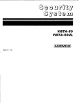
INSTALLATION INSTRUCTIONS
7
\
ADEMCO
ALPHA VISTA
NO. 5130XT
SECURITY SYSTEM
N3122-3
3/89
I
“.
. -----
Specifications
............................ ....... ...... ...... . ... ... . .......
5130XT Security Control
.............................................
4171XTDigital
Communication
interface Board . . . . . . . . . . . . . . . . .
5137 Remote Console
... ...... ...... ....... .... . .. ... ...... .... ..
4131 Remote Keypad . . . . . . . . . . . . . . . . . . . . . . . . . . . . . . . . . . . . . . . . . . . . . . .
4152LM Loop Module . . . . . . . . . . . . . . . . . . . . . . . . . . . . . . . . . . . . . . . . . . . . . . . . .
4208 Zone Expander . . . . .. . . . . . . . . . . . . . . . . . . . . . . . . . . . . . . . . . . . . . . . . . . . . . . . . . . . . . . .
The Limitations ofthis Alarm SyWem
... .... . .... ...... .. . . . .... . ....
Limited Warranty
. .... . ...... ....... ...... ... .. ...... ..... ... . .......
Appendix
A. Cabinet
Mounting,
....... ... .... ........ . ...
... .
. ....
... ..
.. ... .. . ..
...... .... ..
. .. . ... .
.
.. ... .. . ..
.... . . ...
... . .. .... ......
. .. .. .... .
....
...............
.
..... . . .. ... . .... . .....
.... ..
.
.
....... .. . . . . .
. . . . . . . ..
.
..
.. . . . . . .... .. ....... ..
. . . . . . . . . . . . . . . . . . ............
... ..
. ....
... .. ....
.
86
86
86
86
87
87
87
91
93
88
Diagrams
Diagraml.
Diagram 2.
Diagram
Diagram
Diagram
Diagram
Diagram
Diagram
Diagram
Diagram
Summary of Connections
. .................................. .................................. ....................................
24-Pin Connector with Flying Leads
(5130XT Field Wiring interface)
... ....... ...... .... .... . . .... . . .. .. .... ....... . . .
...... ..
KeyswitchWiring
.,.......,,.,.,..,,..
.... ...... ....... ...... ...... ...... .. . .. . .. .
.... . . .
....
3.
Installing the Digital Communication
4.
interface Board (4171 XT) . . . . . . . . . . . . . . . . . . . . . . . . . . . . . . . . . . . . . . . . . . . . . . . . . . . .
. . .. .... . .... ..
and Wiring to4208
..... .... .. ...... .. ... .... . .. .... .. .... ..... .......
.... .. ..
5. 4152LMlnstaHation
6.
5130XTConnection
interfacing
and 4171XTWiring
Connections
Inserting Nameplate
............................................................................. ...................................
7.
8. Wall Preparation for Flush Mounting
Flush Mounting the5130XT/5137/4137
.
.
9.
.. . ....... ...... ..... .. .. .... ... .. . . . .. . ..
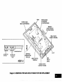
10. Removing Main Circuit Board for Fuse Replacement
Templatefor
Mounting
the5130XT/5137/41
37 (provided
onseparate
sheet)
17
18
19
21
22
25
26
28
29
83
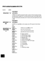
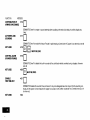
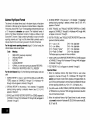
The ALPHA VISTA 5130XT is a microprocessor-based
security control
which provides up to 9 wired zones in the basic product, with expansion
to an additional 8 wired zones when connected to a 2-wire zone expansion bus driven by the optional No. 4152LM Loop Module. The security
control is housed in a wall-mounted plastic enclosure measuring only
8.4” (21.3 cm) wide x 4.75” (12 cm) high x 1.1” (2.8 cm) deep, and is
equipped with a multifunction 12-key digital keypad, a 2-line, 32character multipurpose LCD English language display and a built-in 85
db piezoelectric sounder that meets UL requirements as an alarm
sounder (an external sounder is therefore optional), Connections to the
security control are made via a 24-pin plug-in connector equipped with
flying leads which interface to the wired loops, plug-in DC Power Pack,
back-up battery, optional external alarm sounder, etc.
The security control can be easily programmed from its own keypad, or
from an optional 5137 or 4137 remote console; the control can also be
programmed locally from the 699 Programmer (using a 695-30XT cartridge). Programmed options to establish specific alarm and reporting
features are stored in electrically erasable, non-volatile EEPROM
memory. This means that the unit can be reprogrammed many times
(unlike units equipped with PROMS) and that information which has been
programmed will not be lost in the event of a complete loss of power, For
installer convenience, the control is factory-programmed
to a set of
values that is designed to meet the needs of many installabons. However,
these can be altered by the installer 10 suit the specific needs of a paflicular installation or installation company, following the instructions provided in the programming section of this manual (factory-programmed
values are also shown there).
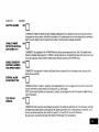
This system also contains abbreviated operating instructions in memory,
designed primarily as an aid to the end user. This feature, which functions when the system is in the armed or the disarmed mode, is activated
by simply pressing any of the function keys for 5 seconds. The display on
the control will then scroll information related to the use of that function.
A plug-in Communication Interface board (4171XT) provides communication capability (central station reporting, etc.) over existing telephone
lines as well as zone expansion connections.
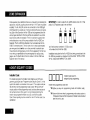
An optional, economical, remote keypad (4131) can be used for arming,
disarming, etc., from a remote indoor location within the protected premises.
This unit is a compact 12-button keypad with two system status indicators
(LEDs) and a built-in piezoelectricsounder
that provides warning and alarm
sounds. Requires a 10-wire connection to reconnection to the control.
An optional remote console (41 37) pmwdes functions similar to that of
the 5137 with one notable exception. It utihzes an LCD display that displays numerics for zone identification and predefine
words for mode,
status, and alarms.
A complete list of optional accessories will be found in a section toward
the end of this manual under the heading “Optional Accessories” (see
Index).
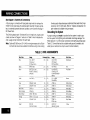
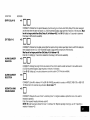
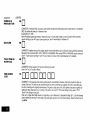
Zone Characteristics
Zone 1:
Programmable Zone, may be used as EOLR supervised Fire
Zone (supports 2-wire Smoke Detectors) or for non-fire usage,
or may be used as a non-fire zone with N.C. contacts only
350-500 msec response.
Zones 2-8
Programmable
response.
Zone 9:
Programmable
response.
Zones,
EOLR supervised,
350-500
Zone, N.C. contacts only, fast 10-15 msec
msec
Back-up 12V DC Battery
DC Power Pack
Mounted externally, A special backbox (4132) is available for mounting the
battery in the wall behind the Control. Rechargeable 12-volt, 1.2 AH Lead
Acid.
Plug-in Power Pack (DC power converter), Plugs into unstitched 2-prong
110 volt AC outlet providing 24-hour service Power Pack (1350) supplies
unregulated 18V DC outpui (700 mA max) for powering the Control.
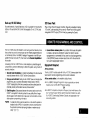
The No. 5130XT allows the installer to call it using switched network phone
lines so that the control/communicator
can be remotely programmed and/
or commanded from a No. 699MD Intelligent Programmer or an IBM compatible Personal Computer (PC). See Note 2 under Remote Capabilities in
this section.
4. Central Station Advisory Note Any condition that causes the system
to initiate a call back to a telephone number from which It can be
reprogrammed or commanded (in fact, even for a local reprogramming
of the EEPROM) causes a unique report to be sent to the central station’s alarm logging digital receiver.
Accessing of the No, 5130XT from a remote location is protected against
compromise by someone attempting to defeat the system, using 4 levels of
security protection
At the premiaas
1. Security Code Handahake An 8-digit Central Station ID code must be
matched between the No. 5130XT and the Central Station.
The No. 5130XT must be used with Its No, 4171 XT Communication
face board if remote programming and/or control is desired,
2. Hang-up and call back Calling the No.5130XT does not directly allow
programming, as a successful handshake merely results in the No.
5130XT breaking the phone line connection and then calling back the
(internally stored) central station service phone number*.
At the centrai station (or the installer’s office/home):
3. Data Encryption: Data passed between the central station and the No.
5130XT ISencrypted for security so that it is very difficult for a foreign
device tapped mto the phone line to take over communication and substitute system compromising information.
*NOTE:
In situations where a service person is on site and the system is
installed inside a PABX, it is ~ossible to initiate a download from
the protected premises by keying [installer or master security
code] + [#] + [1].
Equipment Required
●
●
inter-
A No 699MD Intelligent Programmer that incorporates an internal
modem and a No. 695-30XT Program Carfndge,
OR
An IBM PC compatible computer, a Modem (check with Ademco Factory Technical Support for the specific brand and model to be used),
No. 4130PC Downloading Software Dlakette, and appropriate interconnecting cables.
Remote Capabilities
(See Note 2)
Programming:
All programming functions accessible
No. 699 direct programming.
from the unit’s keypad or via local
Commanding:
There are two types of commands that can be issued to the system:
t.
Control Commands
-To Arm the System in the Away Mode* (1)
-To Disarm the System’ (1)
-To Bypass a Zone
-To Force the System to Accept a New Program Download
-To Shut Down Communication (dialer) Functions (non-payment
of monitoring fees in an owned system)
-To Shut Down all Security System Functions (non-payment for a
leased system)
-To Inhibit Local Keypad Programming (prevents takeover of your
accounts)
‘NOTES:
1, If the system is programmed
#7 will be reported,
repofling
by user, User
2. After the5130XT and the 699 or PC have established valid communication, each console will become inactive The 5130XT will resume
the normal security functions (including responding to faults that took
place during the downloading) after it is commanded to hang up. See
the 4130PC or 695-30XT instructions for details.
The detailed operation of the functions described below is covered in the
Installation Instructions for the No. 695-30XT Program Cartridge and for
the 4130PC Download Software Diskette.
-To Read List of Faulted Sensors
-To Read List of Bypassed Sensors
-To Read 10 Day Alarm History Log
-To Read 10 Day Trouble History Log
-To Read List of Sensors Currently in Alarm
-To Read List of Sensors Currently in Trouble
2. Status Commands
-To Cause the System to Upload a Copy of its Resident Program to
the central station
-To Read System Status:
Arming Status
Ready Status and Current Faults
Presence of Alarms (pastor present)
Presence of Troubles (pastor present)
AC Power Status
Bypass Status and Current Bypasses
for open/close
Remote Communication
Specifications:
. Program Download Time - f minute for a complete program
. Typical Total Time Including Call Up/Call-Back
-3-4 minutes
Remote Command/Programming
Advisory Notes:
. Alarm and Trouble Reporting are disabled during the time that the sys
tern and the central station are linked to each other for the described
functions, following a valid exchange of codes.
.
Keypad entries are ignored during the same time Interval cited above.
●
Should an alarm transpire during the remote program/control
Interval,
the system would not respond to the alarm condition until the remote
mode was ended, The local zones and the Nos. 4139WH, 4190WH,
4192S0, 4194WH, 4196, 4208 and 4275 all store their fault conditions
until they are read by the Control, As such, alarm conditions from the
local and expansion zones would not be missed, only delayed
For each zone used, one of the following zone types must be selected:
1. Entry/Exit Burglary (Delay #l). Assigned to sensors on doors
through which entry and exit will normally take place when the system is armed.
2. Entry/Exit Burglary (Delay #2), May be set for different delay than
above. For use with sensors on overhead garage doors, etc., where
longer delay is needed 10 reach the keypad in the main portion of
the house or building, and more delay is needed to exit the
premises.
3. Perimeter Burglary. Normally assigned to all sensors on exterior
doors and windows requiring instant alarm,
4. Interior, Follower. Delayed alarm only if the Entry /Extt zone IS
faulted first; otherwise, produces an instant alarm, Assigned to zone
covering an area such as a foyer or lobby through which one must
pass upon entry to reach the keypad to disarm the system.
Designed to provide instant intrusion alarm in the event an intruder
hides on the premises prior to the system being armed or gains
access to the premises through an unprotected area.
●
A copy of the program downloaded may be produced from either the
No, 699 Intelligent Programmer or the IBM PC compatible computer,
using those products’ internal report generators, when an optional printer is connected.
5. Trouble by Day/Alarm by night, Can be assigned to a zone which
contains a-foil-protected d-oor& window (such-as in a store), or to a
zone covering a “senstive” area such as a stockroom, drug supply
room, etc., or other controlled access area where immediate notifica.
bon of an entry is desired. During the disarmed state (day), the system will provide latched Control/Console
annunciation (and central
station report, if desired) of openings or troubles (such as sensor
malfunctions or foil breaks) During the armed state (night), violations will initiate an alarm.
6. 24-hour Silent Alarm. This type generally assigned to a zone containing an Emergency button that is designed to irutiate an alarm
report to the Central Station, but which produces no local displays
or alarm sounds.
7. 24-hour Audible Alarm. This type also assigned to a zone containing an Emergency button, but which will initiate an audible alarm in
addition to an alarm report to the Central Station
8. 24-hour Auxiliary Alarm (Control internal sounder only). This type
assigned to a zone containing a button for use in personal emergencies, or to a zone containing monitoring devices such as water
sensors, temperature sensors, etc. Designed to initiate an alarm
report to the Central Station and also provide Control/Console
alarm sounds and alarm displays.
9. Superslsed Fire [alarm on short/trouble
10. Interior that always has Entry/Exit Delay #1 (except that Entry
delay is suppressed in the INSTANT mode). This type typically
ass!gned to an interior zone containing a PIR that covers an area
through which the user must pass to reach the Control for disarming
purposes (whether inside or first entering). ideal for an area such as
an apartment entrance foyer in which a keypad is located.
on open).
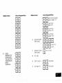
The following is a description of the vaflous zone types available which must be
selected for each physical zone. You may wish to use Table A at the end of this
description to record your selections.
Type 1. BURGLARY ENTRYEXIT (DELAY #l): This zone type is not
enabled after arming until termination of the (EEPROM defined) Exit
delay #1. Upon entry, the Control will simply emit short beeps as a
warning that the system must be disarmed, If Code + OFF is not
entered before termination of the (EEPROM defined) Entry delay
#1, an alarm will be initiated at the built-in sounder, if program
enabled, and an external alarm and latched LCD display. A
system-wide EEPROM defined number of alarm reports for this
zone will be allowed to be transmitted (swinger suppression) in one
armed period, Restorals will be sent when the zone is restored for a
time greater than its physical response time (less than 1 second).
During the disarmed state, a faulted zone will result in a
“DISARMED-Press A to show faults” display. Subsequent
depression of the* key will cause all the descriptors of the faulted
zones to be sequentially displayed. No communicator reports will
be initiated.
Type 2. BURGLARY ENTRY/EXIT (DELAY #2): This zone type is not
enabled after arming until termination of the (EEPROM defined) Exit
delay #2. Upon entry, the Control will simply emit short beeps as a
warning that the system must be disarmed. If Code + OFF ISnot
entered before termination of the (EEPROM defined) Entry delay
#2, an alarm will be initiated at the built-in sounder, if program
enabled, and an external alarm and latched LCD display. A
system-wide EEPROM defined number of alarm reports for this
zone WIIIbe allowed to be transmitted (swinger suppression) in one
armed interval, Restorals will be sent when the zone is restored for
a time greater than its physical response time (less than 1 second).
During the disarmed state, a faulted zone will result n a
“DISARMED-Press *to show faults” display. Subsequent
depression of lhe * key WIIIcause all the descriptors of the faulted
zones to be sequentially displayed. No communicator reports will
be initiated.
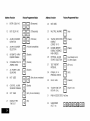
Type 3. BURGLARY PERIMETER While the System is armed, a faulted
zone WIIIinitiate an alarm at the built-in sounder, if program
enabled, and an external alarm, a latched LCD display, and a
(EEPROM selected) communicator report. Depression of any key
will silence the Control’s local alarm sounder for 10 seconds, A
system-wide EEPROM defined number of alarm reports for this
zone will be allowed to be transmitted (swinger suppression) by the
communicator in one armed period. The communicator will transmit a restoral message when the zone is restored for a time greater
than its physical response time (less than 1 second).
Type 5.
BURGLARY PERIMETER, TROUBLE BY DAY/ALARM BY
NIGHT During the disarmed state (day), faulting the zone will
initiate a ‘trouble” display and a latched sounder (beeping), The
Control will beep rapidly along with a latched display of the faulted
zone and the word CHECK. Pressing any key will silence the beeping for 10 seconds, Code + OFF will silence the beeping but will
only clear the display of a zone that had the fault condition
removed.
During the disarmed state, a faulted zone will result in a
“DISARMED-Praaa * to show faults” display. Subsequent
depression of the* key will cause all the descriptors of the faulted
zones to be sequentially displayed. No communicator reports will
be initiated.
Each trouble will result in a “trouble” report (if programmed). A
trouble restoral message will be sent as each zone is restored to
normal condition. The maximum number of trouble reports per
armed petiod will be limited by the system-wide EEPROM number
of alarm reports option (swinger suppression).
Type 4. BURGLARY INTERIOR, FOLLOWER: This zone will always
have Exit Delay W. The zone has an Entry Delay if preceded by a
fault man Entry/Exit zone (type #1 or #2). If not pracadad by an
Entry/Exit zone fault, an immediate audible local (Control) and
external alarm, latched display, and a (EEPROM selected) communicator report are initiated. Depressing any key at the Control
will silence the Control sounder for 10 seconds. A system-wide
EEPROM defined number of alarm reports for this zone will be
allowed to be transmitted (swinger suppression) by the communicator in one armed period. The communicator will transmit a restoral message when the zone is restored for a time greater than its
phys!cal response time (less than 1 second),
During the armed state (night), the local (Control) and external (if
used) alarm sounders will activate and the communicator will
report alarms, A system-wide EEPROM defined number of alarm
reports for this zone will be allowed to be transmitted in one armed
period. Restorals will be sent when the zone is restored for a time
greater than its physical response time (less than 1 second).
During the disarmed state, a faulted zone will result in a
“DISARMED-Press x to afrow faulta” display. Subsequent
depression of the* key will cause all the descriptors of the faulted
zones to be sequentially displayed, No communicator reperk will
be initiated,
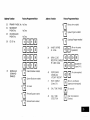
TyfJs 6. 24-HOUR SILENT ZONE: Sensors assigned to this zone, when
faulted, will initiate a communicator report. There will be no local
displays or alarm sounds. Upon keying Code plus OFF, there will
be a memory indication of the faulted zone
A system-wide EEPROM defined number of alarm reports for this
zone will be allowed ‘to be transmitted (swinger suppression) by the
communicator until an OFF sequence is performed. The communicator will transmit a restoral message when the zone is restored for
a time greater than its physical response time (less than 1 second).
During the disarmed state, a faulted zone will result in a
“DISARMED-Prees A to show faults” display. Subsequent
depression of the * key will cause all the descriptors of the faulted
zones to be sequentially displayed. No additional communicator
reports will be initiated.
The burglary portion of the system cannot be armed if this zone is
faulted. An OFF sequence (code plus OFF) should be performed
ptior to arming the system or viewing the faulted zones,
Type 7. 24-HOUR AUDIBLE ZONE: Faulting a zone of this type will
initiate a loud audible alarm externally and at the Control, an LCD
display, and a (EEPROM selected) communicator report. Pressing
any key will silence the Control sounder for 10 seconds. Keying
Code plus OFF will permanently silence the alarm, A system-wide
EEPROM defined number of alarm reports for this zone will be
allowed to be transmitted (swinger suppression) by the communicator until an OFF sequence is performed The communicator will
transmit a restoral message when the zone is restored for a time
greater than its physical response time (less than 1 second),
Type 8. 24-HOUR AUXILIARY ZONE: Faulting a zone of this type will
initiate a steady alarm sound at the Control, an ALARM display, and
a (EEPROM selected) communicator report Pressing any key will
silence the Control sounder for 10 seconds. Keying Code PIUSOFF
will permanently silence the alarm. A system-wide EEPROM
defined number of alarm reports for this zone will be allowed to be
transmitted (swinger suppression) by the communicator until an
OFF sequence is performed. The communicator WIIItransmit a restoral message when the zone is restored for a time greater than its
physical response time (less than 1 second)
Type 9.
FIRE ZONE: Opens in this zone will result in “troubles”. Shorts will
result in alarms. Note: Zone 1 will support 2-wire Smoke Detectors
(using the EOL resistor configuration), Zones 2 through 8 can be
used for heat detectors and pull stations and for 4-wire Smoke
Detectors with external (manual) power interrupt; Zone 9 cannot be
used for Fire.
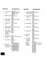
Fire zones may not be bypassed. A fire zone in trouble will not prevent the burglary system from being armed in any mode.
A system-wide EEPROM defined number of alarm reports for this
zone will be allowed to be transmitted (swinger suppression) by the
communicator in one armed period. The communicator will transmit
a restoral message when the zone is restored (less than 1 second,)
Type +0. INTERIOR DELAY ZONE: This type of zone will always have Ent~
delay #1 and Exit delay #1. This zone is not enabled after arming
until termination of the (EEPROM defined) Exit delay #1. If this zone
is faulted, beeps will be emitted by the Control. If Code + OFF is not
entered before termination of the (EEPROM defined) Entry delay #l,
an alarm will be initiated A system-wide EEPROM defined number
of alarm reports for this zone will be allowed to be transmitted
(swinger suppression) by the communicator in one armed period,
The communicator will transmit a restoral message when the zone
is restored for a time greater than its physical response time (less
than 1 second).
During the disarmed state, a faulted zone will result in a
“DISARMED-Press X to show faults” display. Subsequent
depression of the * key will cause all the descriptors of the faulted
zones to be sequentially displayed No communicator reports will
be initiated.
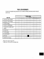
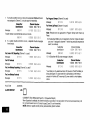
TABLE A. ZONE ASSIGNMENTS
A zone type must be assigned to each physical zone in use For convenience,
selections made
ZONE TYPE
1
t ENTRY/EXIT,
Delay /41 (Burglary)
2 ENTRY/EXIT,
Delay H2 (Burglary)
2
3
4
5
6
the following chart has been provided for checktng off
7
PHYSICAL ZONES
9
10$+II**
8
3 PERIMETER (Burglary)
4, INTERIOR, FOLLOWER (Burglary)
5 TROUBLE BY DAY/ALARM
(Burglary)
BY NIGHT
6. 24-HOUR SILENT
7, 24-HOUR AUDIBLE
8 24-HOUR AUXILIARY
9 FIRE ZONE’
I
10 INTERIOR DELAY (Burolarv)
‘ Physical Zone 9 cannot be used for Fire,
“ Available when 4152LM and 4208 Zone Expander
used
I
12*+’ 13**
14**
15**
16*W 1w+’
Zone expansion to an additional 8 zones is achieved by first installing the
optional No. 4152LM Loop Module onto the No 4171 XT (after it has been
Installed), The No, 4152LM can then be connected to a No. 4208 Eight
Zone Expander by a srrgle par of wires providing both power and slgnalIing. Each of the 8 zones on the No. 4208 can be programmed from the
various types described in this manual that are available for use on the
basic 9 zones, wtth one exception. There k no ablity to support 2 wire
smoke detectors on any of the zones available in the No. 4208 Zone
Expander. The No. 4208 Zone Expander may be located near the No.
5130XT or remotely from it. The two wire run to t should utihze twlated
pair wiring and should not be run in close proximity to protected premises intercom wiring [at least a 3-inch (8 cm) separation]. For the maximum wiring run permissible to the zone expander for various wiring
gauges, see the Specifcatons Section relative to the No. 4208 Zone
Expander later in this manual.
IMPORTANT
In order to utilize the No. 4208 to obtain zones 10-17, that
product’s DIP switches must be set as follows”
Installer Code:
❑
The installer programs the Installer Code mtially as part of the programmng procedure (see “Programming the Security Control”) In this
system, the installer E considered to be user #1. Tt’e installer code permits re-entry mto the programming mode (unless ’98 has been previously used 10 exit the programming mode) and also allows access to
the normal functions of the system. During initial programming, the
installer also programs the Master security code into the system,
Open/Close reporting must be enabled for User #1 for this code to be
operational.
nom
2
3
4
5
(as If set for sensor numbers 113-120, as cited
in the instructions for the No. 4208)
Installation instructions for the No. 4152LM and wiflng connections to the
No. 4208 are provided in a subsequent section entitled “INSTALLATION
OF No. 4152LM AND WIRING TO No. 4208”.
000
assigned during programming.
‘ns’a’’ercode(user”)’
Installer exits programming mode with:
*99 (allows re-entry into programming
mode with installer code).
or
●98 (does not allow re-entry to programming mode unless system IS
first powered down and then repowered). Installer code is disabled
when this exit is used.
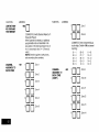
Master Security Code:
The Master security code can be used to assign up to thirteen secondary
codes (to users #3-#1 5); it can also be used to remove all secondary
codes from the system (individually), The person to whom the Master
code IS assigned is considered to be user #2. In some applications
(commercial installations, for example), user #2 (with Master code) will
be the main user of the system (see Application t on a following page).
In other apphcations (such as In an apartment complex, for example),
user #2 (with Master code) may not be the actual end user of the system
(see Application 2 on a following page).
Secondary security codes are assigned by user (with Master Code) as
follows
Master Code + CODE key + User # (03-15) + Secondary Code
The system will emit a single beep when each secondary code has been
successfully entered.
Note
When a secondary code is inadvertently repeated for different
users, or one user’s code is another’s duress code, the lower user
number will take priority.
Individual secondary security codes can be deleted by user #2 (with
Master Code) as follows:
Master Code + CODE key + User # (03-1 5) + Master Code
Note
All security codes, master and secondary, permit access to the
system for arming, disarming, etc.
Secondary (Temporary)
Security Codes:
As stated previously, up to thirteen secondary codes can be assigned to
users 3 through 15 The configuration m Application 1 shows that secondary (or temporary) codes may be assigned by the primary user (user
#2) to as many as thirteen employees, each with a unique code. Note
that user #3 can also assign secondary codes to users 4-14 if required,
but in the typical arrangement shown in Apphcation 1, there may never
be a practical need for this. If so, the primary user (#2) can elect to omit
user #3 when assigning secondary codes.
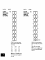
In the configuration shown in Application 2, user #3, who is the primary
user, may need to assign secondary (temporary) codes to maids, cleaning persons, etc. Since the system allows user #3 to assign secondary or
temporary codes to as many as eleven users (4-1 4), this need can be
met. User #3 cannot assign (or delete) user #1 5’s code, which is strictly
under the control of user #2, who may be the building manager or owner
in the configuration shown m Application 2. See Table B, which illustrates
the various levels of authority that exist for security codes.
User #3 can assign secondary (temporary) codes for users 4-14 as
follows:
User #3 Code+ CODE key+ User # (04-14)+
Secondary Code
User #3 can delete secondary codes assigned to users 4-14 as follows:
User #3 code+ CODE key+ User # (04-1 4) + User #3 Code
TABLE B. LEVELS OF AUTHORITY
SECURITY CODES
User
No.
Can assign or delete
Secondary Code of Usen
#1(Installer)
#2
#3
#4 -#15
NONE
#3 through #15
#4 through #14
NONE
FOR
APPLICATION 1
MASTER SECURITY CODE
MAIN USER
dxlmluserw
I
CAN ASSIGN TEMPORARY CODES TO: 1
J
?
EMPLOYEE,
CLEANING PERSON,
(Users 3 thru 15)
ETC.
K
l--c
Note: All codes can Arm/Disarm
‘User #3 can assign secondary
1A secondary
❑
❑
00
“s?r!43+
DU
User#4
the System
codes to users 4-142
(temporary) code is assigned as follows:
User #2 (Master) Code + CODE key + User # (03-1 5) + Temporary
Code
‘User #3 can assign temporary codes as follows”
User #3 Code + CODE key+ User # (04-14) + Temporary
Code
❑
❑
1=8
UU.ser#ll
UOlJser#12
APPLICATION 2
BUILDING
MANAGER,
(User lf2)
MASTER SECURITY CODE
ETC.
‘0000
I
CAN ASSIGN SECONDARY CODES TO 1
Userl#2
nnnLE&Erl
E3&!EE1-.mi!i!o
use,,
User #15
CAN ASSIGN
TEMPOiARY
TEMPORARY
SECURITY CODES
CODES TO 2
+
MAID, CLEANING PERSON,
(User #4 -#14)
7
-
ETC.
z
z
❑
❑
00
User #4
00
User #5
User #6
Note: All Codes can arm and disarm the system,
4
* This code, although actually a secondary code, will serve as a
master security code for the apartment owner, etc. since user #3 is
the primary user of the system in this application,
<
~A secondary code is assigned as follows:
Master Code + CODE key+ User # (03-1 5) + Secondary Code
2A temporary code is assigned as follows:
User #3 Code + CODE key+ User # (04-1 4) + Temporary Code
❑
❑
on
User #7
00
User #8
El❑ l
•1❑ n
ElITI
El❑ o
•1❑ o
N
❑❑o
User #9
User #10
User #11
User #12
User #13
User #14
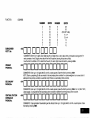
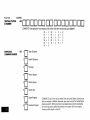
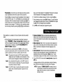
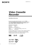
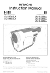
(See Diagram 1, Summary of Connections)
A 24-pm plug-in connector with flying leads is provided to interface the
5130XT to the wired loops, the external alarm sounder, the back-up battery, to externally powered dewces (auxiliary current), and to the plug-in
DC Power Pack,
of wires used in these harnesses is identical to that used in the 24-pin
connector with 18-inch leads. Refer to “Optional Accessories” for
part numbers of available wiring harnesses.
Grounding the Svstem
.
A proper earth ground must be provided for the system in order to protect the system from lightning and electrostatic discharge damage. The
White lead (cm 11) on the 24-~ln connector is the earth around lead (see
Table C). Connect this lead to” a suitable earth ground (a-metallic cold
water pipe or electrical box may be used in some locations).
The 24 flying leads, each 18 inches (46 cm) In length, are uniquely color
coded, as shown in Diagram 1 and also in Table C wtlich indicates the
color, usage and pm connection for each lead.
Note:
Optional 30-ft(9 m) and 15-ft (46 m) wiring harnesses with a 24-pin
connector at one end are available for interface wiring, Color cod!ng
TABLE C. WIRE ASSIGNMENTS
Wire Color
Blue
Usage
DC(-IINPUT
(from
DC
connector Pins
(12) (24)
(from
plug-tr
Power
While
EARTH
Black
BATTERY(-)
DC
Pack)
(3ND
REMOTE
and
AuX
plug-n
Power
BATTERY(+)
Red
[10)
(22)
AUX/REMOTE
Redl
Black
CONSOLE/EXT
ALARM
(-)
Pack)
(23)
CONSOLE
PWR
Wire Color
RedlGreen
[11)
GROUND
V<olel
Usage
DC(+)INPUT
(9)
(21)
SOUNDER
PwR
(+)
ExT
ALARM
Brown
SOUNDER(-)
Gray
ZONE
Tan
ZONERETURN
(7)
(20)
(19)
ZONE4(+)
ZONE5(+)
Wh[tel
Wh,te/Red
ZONE
2[+]
(6)
(18)
ZONE
White/Blue
White/Orange
ZONE
3(+)
(5J
(17)
ZONE
9(+)
Whl!e/Biack
While/Brown
ZONE
1 RETURN
(4)
(16)
ZONE
7(+)
Whte/Vlolel
(8)
RETURN
Ora~ge
ZONE
1(+)
Pink
ZONE
RETuRN
NC
Greeo
DATA
IN
(Remole
Console)
Loop
6(+)
White/Yellow
Green
(3)
(15)
ZONE
8(+)
Wh,te/Gray
(2)
(14)
ZONE
EOLR
1(+)
LOOP
Red/Yellow
[1)
(13)
DATA
OUT
Yellow
[Remote
Console)
.s, .
,0.
M.XIMUM
OF T!WIEE 2-W(RE SMOKE
OR COMBUSTION
DETECTORS
(BRK 1403 24C0 2400TH.
.
F
2.
?,.
W(TH
,(s,,0
2451THI
c...,
.,.,,,0,.,.,”
CO,t+cm,o.s
<,..,,0
...,,.,
,.,.
.“,..,
MU,,
,0,,0.
..0,..,,
”.
.,,,
.,s0.
ST. . . . . . .0,4
.,,,,.
”....”
. . mm,,
,E!zkI-
. . . . ...0.
FLYING
w“.
..”
l-l
1451 2451
L
ALL
,(R5 ,.0,,.,,0.
,,.0s
,. ,0.,.
.0
!,*
+—
,.
,,.
. .
.N,.
!TC. ED
0.,,,,
,...,
4,37/5137
ONLY (ORIONALI
:,
T0t5137
RED LEADS
‘~
~
+
~w.c!.l
. . . m.,.
- I (m.. !4,,,
.(2,
,r.,, m., . ,2V
P&tfi:::&cmAMU,
+
I E&’:.”B:;:&
C,TERN., 81,”
1:
l______
;-------m~’~~~+””
OPTIONAL 4148 RELAY MODULE
______
L -------------
3 AMP FUSE
[SL::::O)
,,,.,.,.s,....s
w!,.
El
,...
,.s,s
2..,
SAT7E*Y
,s,0
,.0,
.0,..0
NO *,.
ON
ON ,..
<.,0,,
,0.,
$“$6
. . A.? . . . . . . . . . .
ACtwo
NO *2,
‘Ax
70,
?81
,0 ZONE
E,,,TO.
Loop ‘~s, sTANc* 3~ 0“.s
*TO
s~~~~$y’w
; =,ypy
, ,,.s, .,,.0.s,,
(P,, , , 0R8,~
!,,
WETURN
, —,...
I ‘..o~’~.
; =:~p
I . ..0s..
,“0.,
Z!WERETUEU,PIN
Z70R8,
.
I
,
,->%,”.!!:3
m,.
‘EOLR
*
s!.”,
TO ZCWE mm..
(P,. 2, 7 ma)
TO ,0.,
.,,.,.
,,,?4 ,
,0.,
! ,,
SOW,”S,C.
CS.O..,
.,
A
L!L_2!lw%%www
“ ,0.,
,.0.,
“,,.
,,,
.0.,
7 . . .
.,
!,,..
, ..”
...,,0.,
. . .
R...,,
,, NOLo..,. .“.),.s,!
s,, ,,., ,. ,.,,..,.,!0.
& w., m,mow.
,,.0
R.
.,0s..
.0...,,,
Diagram 1. SUMMARY
A ,,.,
(PIN 4,,
,.0,
.,”,.,,,”
LO.,
,“s,
,“s,
0..,.,
TO
. . . . . . . . .. . . . . . .
ASa Pmr,c,)m
,.s,...,,0.,
,0.,
.“,.
50
LEA.
BLACK (P!N 101TO RED (PIN 23) *
., O,, ELLOW ,,.0,,,.
,,,.
,,
*WH,TE,.,WN
OF CONNECTIONS
,.,]
,,.O,,,.
.,,
::
, 0.,)
‘.,
. . . . . !*,, . . . . . . . . . . . .
,,,
,7ETLJ,7N(WW2,
,UJOO”
M.
‘ ,0,.
!lIm2@
D“”m
mzaw
*
“m,.
12VDC
----
(-)
!?v:c~~
A
II
t I
2
w.,.
,.s . . .
,.. ,,, m
* ,0”, ”..,.,,
.
.n
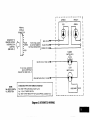
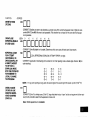
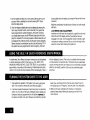
Remote Keyswitch Operation
ISEE NOTE BELOWI
,
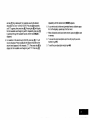
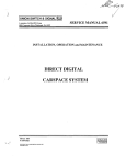
RECORDING
INSTALLATION
DATA
When all interface
wiring is completed,
record wiring usage
in the spaces provided on the Wire
Assignment
tag
attached
to the
wires on the 24-pin
connector. This will
provide a permanent record of the
interface wiring connections for future
servicing.
PINS ~3-24
‘d
SEE
WIRING ASSIGNMENT
TABLE IN TEXT
NOTE
TO REMOVE cONNEcTOR FROM CONTROL 60ARD
AFTER INSERTION, SOUEEZE TAB AND PULL
OUTWARD WITH A SIDE TO SIDE ROCKING MOTION
Diagram 2.
24-PIN CONNECTOR
WITH FLYING LEADS
(5130XT WIRING iNTERFACE)
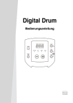
& Wiring
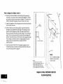
An optional Remote Keyswitch may be used for remote arming and disarming (this is an installer-programmed
option). A normally-open momentary
switch is connected across Zone 7 (which must be given up as a protection
zone). A momentary short of the zone will arm the System in the AWAY
mode; if the key is held (short maintained) for over 3 seconds, the System
will arm in the STAY mode. When a momentary short is applied subsequently, the System will disarm. A keyswitch tamper (normally-closed)
switch wired in series with zone 7 will disable keyswitch operation until the
system is next disarmed via a keypad, if activated. Refer to Diagram 3 for
Keyswitch wiring details.
NOTE: Regardless whether End-of-Line supervision is selected or not (in
Address ’41 ), an end-of-line resistor must still be used for proper functioning of the keyswitch.
r
-——
-—
I
I
———
-——
.
I
IREADY)
RED
I
I
I
I
I
I
GREEN
I
REMOTE
KEYPAD
I
CONNECTOR
0
CONNECTSTO
REMOTE KEYPAD
INTERFACEON
CONTROL
(SEE DIAG.1)
———
(ARMEDI
I
I
RED
BLUE
GREEN
TO FLYING
LEADS
ON 1O-PIN REMOTE
KEYPAD
CONNECTOR
Q
BLUE
[
RED
GREEN
A
(PlN3)-
1
(PI N6)+
(PIN
d
I
5)4
I
I
I
I
I
I
I
I
I
I
?
I
I
D
I
n
I
TAMPER
SWITCH
IN. C.)
I
wHITE/vlo
LET(Pl
N16)4
I
I
LOCK
TO
FLYING
LEADS
ON
24-PIN
INTERFACE
CONNECTOR
(SEE DIAG.
1)
I
SWITCH
(N. O.)
1
1
ZONE
RETURN
(PIN
2, 7 OR 6) =
[
I
I
I
I
SUGGESTED
NOTE:
No. 4073-70
UL LISTED
IS NOT
TEM.
A
PARTS
No.
9787
No.
112
TYPE
NO.
4073-70
NC.
FOR
SLIM
TAMPER
HIGH
REMOTE
DOU8LE
LED
KEYSWITCH
I
PLATE
I
SWITCH
SECURITy
KEY LOCK,
D
1000
SPRING
LOADEO
I
(NO.)
!
L
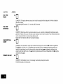
Diagram 3. KEYSWITCH
WIRING
—————
————
OHMS
————
EOLR
I
I
.—
I
I
-
Optional Remote Keypad Connection
(4131)
An optional remote keypad (4131 may be used with the System. Two
10-pin femaie connectors have been supplied for keypad interfacing
to the 5130XT Control (see Diagram 1, Summary of Connections).
The two connectors, which are identical, are equipped with colorcoded flying leads that are 12 inches (30 cm) in length.
One of these connectors is attached directly to the mating 10-pin male
connector on the remote keypad (the connector can only be inserted
one way, and will lock in place).
Optional Remote Console Connection (5137 or 4137)
An optional Remote Console (5137 or 4137) can be used with the
System. Connections are as follows:
513714737
Lesds
RED
GREEN
YELLOW
BLACK
The other connector is connected to the 5130XT Control via a “straight”
male-to-male 10-pin adapter (supplied).
Specific information regarding the use of the adapter and connection to
the 5130XT Control is provided in the section entitled MOUNTING THE
5130XT.
BLUE
to
to
to
to
to
24-pin Connector
Flying Leads
RED/BLACK (Pin 22)
GREEN (Pin 1)
YELLOW (Pin 13)
BLACK (Pin 10) - Connect also to (-) output of optional separate No.1 350 Power
Pack.
(+) output of optional separate No. 1350
Power Pack.
Refer also to Diagram 1 for the above connections
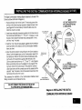
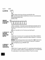
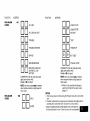
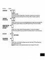
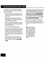
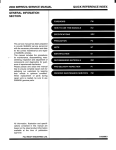
The Digital Communication
Interface Board is attached to the rear of the
Control as follows (refer also to Diagram 4).
NOTE:
VOLTAGETRIGGER OUTPUTS
NOT A USABLEOPTION IN A
UL INSTALLATION.
1 Remove the back cover on the Control. The securing screw at the
left front of the Control must be removed to release the back cover
(see Diagram 6 for screw location). Discard the back cover, but
retain the screw for use later.
2 Insert three small plastic standoffs (supplied) into the three holes on
the Control board identified as “A”, “B” and “C” in Diagram 4. Insert
the end of each standoff into these holes, pressing them in firmly
until they “snap” mto place.
3 Insert the 13-pin male-to-male adapter (supplied) into the interface
socket pin holes on the underside of the Communication Interface
board, as shown.
4 Attach the Communication Interface Board to the Control board as
follows, Guide the adapter pins (on the Communication board) into
the interface pin holes on the Control board, simultaneously allowing the ends of the standoffs to partially enter the holes in the
Communication board (shown as “A”, “B” and ‘(C” in the Diagram).
Before proceeding, make sure the adapter pins are properly entering the pin holes on the Control board. Then press the Communication board down until the connector pins are fully seated and the
standoffs “snap” into place in the Communication board, thus holding the board securely to the Control.
This completes the installation of the Communication
Wiring connections are not made at this time.
Interface
ARO
board.
(
DO NOT CONNECT THE OUTPUT OF THE 4171XT
TO A FIRE OR POLICE HEADQUARTERS
Diagram 4. INSTALLING
COMMUNICATION
THE DIGITAL
INTERFACE
BOARD
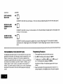
The optional No, 4152LM Loop Module is installed onto the No 4171 XT
Digital Communications Interface board as follows, referring to Diagram 5.
a. Note the 8 square-shaped
connector pins on the 4171 XT board.
Position the 4152LM board over the 4171 XT board so that these pins
engage the mating sockets (header) on the underside of the4152LM.
Press the 4152LM down until the pins are fully seated.
b. Secure the No.4152LM by means of 3 screws (supplied). Connect two
wires from the loop terminals (1 and2)onthe4152LM
to terminals 11
and 12 (respectively) on the 4208 Zone Expander. For information on
wire usage, etc., refer to a previous section entitled “ZONE
EXPANSION”.
SECURING
SCREWS (3)—
y
HEADER
&-
/
No. 4152LM
LOOP MOOULE
v
‘-!Jg=&
‘cONTROLBOARO
CONNECTOR
PINS
Diagram 5. No. 4152LM INSTALLATION
AND WIRING
TO No, 4208
There are three methods that may be used for mounting
Control, as follows:
the 5130XT
viewing angle, as indicated in a section toward the end of this manual
(see “LCD Viewing Angle Adjustment”).
1.Surface Mounting” This type of mounting is possible only when a
battery backbox is not required (battery back-up power will be supplied from a remote location) and when the digital communication
interface board is mounted to the unit using the No. 4143 Extender
Ring to increase the depth of the unit.
2. Flush Mounting: This type of mounting is used when the battery
backbox is required ‘or support of the back-up battery in the wall
behind the 5130XT, u when the No. 4143 Extender is not attached
to the rear of the 51 ~OXT Control. This mounting method is also
applicable if a “rough-in” ring (41 33) has been installed in the wall
in a new construction application.
3. Cabinet Mounting: In buildinas usina concrete, cinder block or
brick wall construtiion, the sufiace o; flush mounting method above
may not be practical, and a third method using a wall-mounted
metal cabinet can be used (see “Optional Accessories”). The
5130XT Control is mounted in a cut-out specially provided for lhis
purpose in the door of the cabinet, and the back-up battery (if used)
is installed within the cabinet, Also available for use within the
cabinet are connector blocks which can be used to connect the
5130XT flying leads to the field w!nng, Instructions for this type of
mounting are provided in Appendix A toward the end of this manual.
Proper selection of mounting location and height is important for optimum
viewability of the LCD display on the control (or 5137 remote console), A
location in which hghting is directly above the control should be avoided,
since this can shadow the display. For optimum viewing, the control
should also be mounted so that the display is below eye level to ensure
that the system’s user will look down at the display. In the event that the
control is mounted at a height that does not offer optimum viewing for the
system’s user, an adjustment can be made subsequently to change the
Surface Mounting:
NOTE:
SURFACE MOUNTING IS THE ONLY MOUNTING
M~HOD THAT MAYBE USED IN A UL INSTALLATION.
Use the template provided (on a separate sheet) to mark the positions on
the wall for the screw mounting holes and the cut-out for the interface
wiring. Use wall anchors for the screws and make the cut-out in the wall
no larger than indicated.
Pull the interface wiring in the wall through the cut-out. Splice these wires
to the 24-pin interface connector wires as indicated in Diagram 1 and in
Table C previously. Insulated solderless wire splices (such as Ademco
No. 311 ) may be used for splicing. Check wira connections carefully
before splicing.
Note: If the optional 15-ft (4.6 m) or30-ft (9 m) wiring harness has been
used for interface wiring, splices will not be necessary behind the
control since these harnesses are terminated with a 24-pin connector which can be connected directly to the 5130XT,
If the 4131 Remote Keypad is being used, splice those wires to the wires
on the 10-pin connectors supplied for this purpose, being sure to match
wire colors. Be sure to insulate all splices
Remove the Control’s back cover. The securing screw at the front of the
Control must be removed to release the back cover (see Diagram 7 for
screw location). Pass the interface connector(s) through the opening in
the back cover and then mount the back cover to the wall surface with
screws.
Install the No. 4143 Extender Ring onto the back cover (see the instructions accompanying the No. 4143).
d. Install the Digital Communication
Attach the interlace connector(s) to the board at the rear of the Control
as follows, referring to Diagram 6:
Use the securing screw (supplied with the No. 4143 Extender Ring) to
secure the Control to the back cover (see Diagram 7 for location of screw
hole), then insert the small ALPHA VISTA XT nameplate supplied into the
recessed opening to cover the screw head, as shown in Diagram 7.
a.
Attach the 24-pin connector
the bottom of the board.
to the mating interfacing
pins located at
b. Attach the 10-pin connector (if used) to the Remote Keypad connector
(1 O-pin socket) at the top of the board via the ‘<Straight” male-to-male
adapter supplied. Important:
Be sure to orient the connector with
BLACK lead (pin 1) to the left (when viewing the5130xT from the rear).
c. On the Digital Communication
interface board, attach the interconnecting wires to the terminal block as follows, referring also to
Diagram 6~
Communication Interface
Board Terminal
1
2
3
4
5
‘Connect
Note:
Wire
Assignment
Ground Start *
Incoming Phone Line (Tip)
Incoming Phone Line (Ring)
Handset (Ring)
Handset (Tip)
to BLUE lead on 675 Ground Start Module.
Ground start not usable in a UL
installation.
Interface
board (see Diagram
4).
Attach the main body of the Control to the Extender Ring, which is attached to the wall-mounted back cover. The Cdntrol is properly attacheo
when it “snaps” into place.
DIGITAL
COMMUNICATION
BOARD (I NSTALLEO)
lC-PIN
REMOTE
KEYPAD
CONNECTOR
(IF USEO}
GROUND
\
“
LINE
(TIP)
PHONE
LINE
[RING)
1
INCOMING
STRAIGHT
l@ PIN
MA LE-TC-MALE
ADAPTER
\
START
PHONE
(RING)
\F
r]
r
HANDSET
(TIP)
“ GROUND START NOT USABLE
IN A UL INSTALLATION.
L/L\
/
BLACK
LEAO
(PI N-1 )
THIS
J+=j+”
REAR OF CONTROL
(BACK COVER
REMOVED)
SIDE
2JLL
INTERFACE
CONNECTOR
Diagram 6. 5130XT CONNECTOR
INTERFACING
AND 4171XT WIRING
CONNECTIONS
INSERT
INTO
AREA
NAMEPLATE
RECESSED
(COVERS
SCREW)
OARMED
If a“rough-in” ring (4133) has been previously installed in the wall (during
newconstruction),
disregard stept andproceed tostep2 since the
required opening for the Control is already present. If a wall plate (41 36)
is installed over the rough-in ring, remove the plate to expose the
opening.
1, Cutanopening
measuring 4-5/l 6''(llcm)
high by7-%''(20 cm)
wide between studs in the wall. The opening must be no less than
1-Yz” (4 cm) from either stud. Avoid cutting the opening any larger
than that specified. See Diagram 8.
a
g
Flush Wall Mounting:
Note:
OPOWER
Aspecial `'trim ring' 'has been supplied for installation between
the wall and the Control for those cases where the opening
has inadvertently been made too large (over-cutting), The Control fits into the recess in the trim ring which will extend %“ (1.3
cm) beyond the Control front panel, andthus cover any opening that might otherwise be visible as a result of over-cutting.
2. Remove the back cover onthe Control. Thesecuring
screw at the
front of the Control must be removed to release the back cover (see
Diagram 7 for screw location). Discard the back cover, but retain
the screw.
Note
\
SECURING
SCREW
Diagram 7. INSERTING
NAMEPLATE
Make sure that thedigital communication interface board is
mounted tothe5130XT
(and the No.4152LM Loop Module, if
applicable), as indicated previously. .
3. install the Battery Backbox (4132). (Disregard this step if battery
back-up power is supplted from a remote Iocat!on.) If battery backup power IS not supplied from a remote location, the backbox suppIled must be installed behind the wall opening to support the backup battery that must be used. Install as shown in Diagram 8, with
“lip”of the backbox hooked over the bottom edge of the wall
opening.
Insert the battery into the box, and make connections to its terminals as follows, using the two 12-inch (30 cm) Red and Black leads
(equipped with FAST-ON connectors at one end) that have been
supplied, See Diagram 1.
a Splice the wire end of the RED 12-inch Ieadtothe Red lead (pin 23)
coming from the 24-pin connector (an insulated solderless wire
spiicesuch as Ademco No. 311 may beused). Connect the other
end (FAST-ON connector) of the 12-inch RED lead to the positive
(+) terminal on the battery.
b Splice the wire end of the BLACK 12-inch lead to the Black lead
(pin 10) coming from the 24-pin connector (be sure to use an insulated wire splice). Connect the other end (FAST-ON connector) of
the 12-inch BLACK lead to the negative (-) terminal on the battery.
Note
For UL Listed usage, utilize the 4132-1 (optional) battery
box cover’ Feed the two battery wires through the two
openings in the cover and insulate their connection to the
battery with the plastic insulators supplied with the 41321. Insert the battery into the 4132 backbox and place the
4132-1 cover over the top of the battery.
5, If a Remote Keypad is being used, splice the field wires in the wall
to the wires on the 10-pin connector supplied for this purpose,
being sure to match wire coiors.
6. Attach the interface connector(s)
referring to Diagram 6:
a. Attach the 24-pin connector to the mating interfacing pins
located at the bottom of the Control board.
b, Attach the 10-pin connector (if a Remote keypad is being used)
to the Remote Keypad connector (1 O-pin socket) at the top of
the Control board via the “straight” male-to-male adapter
supplied.
iMPORTAN~
Be sure to orient the connector with BLACK lead (pin 1)
to the left (when viewing the 5130XT from the rear), as
indicated in Diagram 1.
7. On the Digital Communication interface board, attach the interconnecting wires to Its terminal block as follows, referring also to
Diagram 6:
Communication interface
Board Terminal
4 Pull all interface wiring in the wall through the opening previously
made. Splice the appropriate wires to the 24-pin interface connector
as indicated in Diagram 1 (Summary of Connections) and in Table
C previously. Insulated soiderless wire splices (such as Ademco
No. 311 ) may be used for splicing. Check ail wire connection
carefully before splicing.
Note: If the optional 15-ft (4.6 m) or 30-ft (9 m) wiring harness
has been used for interface wiring, splices at the Control
will not be necessary since these wiring harnesses are
terminated with a 24-pin connector which can be connected directly to the 5130XT.
to the Control board as follows,
2
3
4
5
Wire
Assignment
Ground Start’
Incoming Phone Line (Tip)
Incoming Phone Line (Ring)
Handset (Ring)
Handset (Tip)
*Connect to BLUE lead on 675 Ground Start Module.
Note:
Ground start not usable in a UL installation.
l!:
Refer to Diagram 9 for Steps 8,9 and 10
l.l I;’MIN
8 Mount the Control as follows. Insert securing screw (previously
removed) in screw hole at front of Control (see Diagram 7) and attach metal clip (at the rear) as shown in Diagram 9. Turn the screw
until the clip enters the guide point about % of an inch (3 mm).
111
h
II
\
73/4’ (20 cm)
II
II
9 Insert the straight end of the flat spring into the slot at the other side
of the Control, as shown.
10 With the metal clip in the vertical position, mount the Control by
hooking the spring behind the right edge of the opening so that it
holds the Control against the inside of the wall, as shown at (A),
Now turn the screw (from the front of the Contr?l). The clip will turn
until it hits the clip stop and will then draw the Control forward (B).
Continue turning the screw until the Control is flush against the wall,
Then, making sure that the Control is straight, tighten the screw
further to secure the Control firmly in posifiorr DO NOT
OVERTIGHTEN!
//
‘“l
II
~ ~
BOX
11 Insert the small ALPHA VISTA XT nameplate supplied into the
recessed opening to cover the screw head at the front of the Con
trol, as previously shown in Diagram 7.
!
IIIL
111
II
Ill
Ill
Ill
Ill
Ill
Ill
\
;~,,(,lcm)
‘\
k)
I l_l~
1;
.&’
4
f
BACK BOX
II
Ill
Ill
I
NOTE :
A ROUGH-IN RING (4133) MAY SE
PRESENT IN NEW CONSTRUCTION
1F SO,
SIMPLY REMOVE COVER PLATE 10
EXPOSE FRAMED OPENING SUITABLE
FOR FLUSH MOUNTING oF THE CONTROL
Ill
II
‘1
1,
II
II
I
WSTUDS
I
NOTE:
1
~
For UL Installation, Battery
Back Box cover (4132-1)
must be used
II
J.
~~.
‘,
\
,,
‘\
\
‘..
~.
Diagram 8. WALL PREPARATION
FLUSH MOUNTING
. .. __
WALL
(4.(T)
\
FOR
\
A\
.
I
METAL
/
CLIP
SPRING
(NOTE
CURVED
END)
\
B
/
w
IF SHEETROCK
BREAK
NOTE :
4-5/16”(11
cm)H X 7-3/4’’(20
THE 5130XT/5137/4137
CONTROL
IS TOO THICK,
OFF THE SCORED WING
cm) W
WALL OPENING IS REQUIRED
FLUSH MOUNTING.
Diagram 9. FLUSH MOUNTING
SHEETROCK
CLIP STOP
FOR
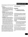
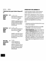
Installer options are stored in non-removable, electrically erasable, nonvolatile EEPROM memory, These options must be programmed for the
parhcular installation to establish its specific alarm and reporting
features.
The security control may be programmed from its own keypad (the most
convenient method) or from an optional 5137 or 4137 remote console, or
can be programmed locally from the 699 Programmer. Information
regarding the Programmer is included with the No. 695-30XT Programming Cartridge.
When programming from the security control, prompts for each field description and field number will be displayed on the 2-line, 16-character
LCD display; also, each entry is displayed as it is keyed in. After programming, values that have been entered in each field can be reviewed
and, if necessary,
modified.
The system is factory-programmed
to a set of preset values, which can
be altered by the installer to suit the specific needs of a particular installation or installation company. The preset values are detailed in the Factory Programming Table.
information
is stored in non-volatile
EEPROM
Note: Proarammina
me~ory in th~s Control (removal of power will not result in the
loss of the information). Consequently, it is possible to program
the Control at any time — even at the installer’s premises prior
to the actual installation — Simply apply DC power temporarily
to the Control and then program the unit as desired.
When programming
from the Control, note the following:
1. Enter the Programming mode by simultaneously depressing the *
and # keys within 30 seconds after power is applied to the Control, or subsequently by keying the code 5 + 1 + 3 + O followed by
depression of CODE + O + O keys. Once an installer code is programmed, use it instead of5130 (as 5130 is no longer present) to
gain access to the programming mode.
2. Immediately following entry into the program mode, the following will
be displayed:
Program Console
* Fill # View .00
To program a data field, key * plus Address (for example, * 01), then
make the required entry To simply review a data field, key # plus
Address.
3. When a data field has been completely programmed, the Control will
“beep” three times and then automatically proceed to, and display,
the next data field address to be programmed.
4. If the number of digits that you enter In the data field is less than the
maximum permitted (for example, phone number), then the Central
will display the last data entered. To proceed, the next data field
address to be programmed must then be entered (for example, * 05).
5. If an address is improperly entered, the Control will display FC. If a
program entry is improperly entered (for example, a larger number
than that which is permitted), the Control display will go blank. In
either case, simply re-enter the number.
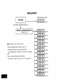
The following is a description
of commands
FUNCTION
PROCEDURE
ENTER PROGRAMMING MODE:
necessary for programming:
1. POWER UP, then depress * and # simul2.
3
taneously within 30 seconds of powering up.
OR
Initially, Key:5+l
+3+ Oplus CODE key+0
+0
OR
After Installer Code is programmed, key:
Installer Code + CODE key + O + 0.
Notes
User #1 (installer) must be enabled (in
Address *52) if Type 3 method of entry
is to be used
Type 3 method of re-entry to the
programming mode is inhibited if the
programming mode is exited via use of
*98
Type 1 method of entry can always be
used unless console programming has
been locked out by the remote
downloader.
EXIT PROGRAMMING MODE:
SPECIAL
MESSAGES
FC = FIELD CODE ERROR (program entry mistake, re-enter the data),
*99
(always allows re-entry to programming
mode via Type 3 entry method above).
After powering up, ****DISARMED****
READY TO ARM will be
displayed after approximately 7 seconds. Enter the programming mode
by simultaneously depressing * and # within 30 seconds. The System is
factory-programmed
with preset values (see Table D) that can be altered
via the programming instructions that follow the table.
*98
(inhibits re-entry to programming
Type 3 entry method).
FACTORY
Not&
mode via
When the programming mode is exited, a
1-nimute set-up period must elapse before
the system can properly function
ADVANCE TO FIELD:
* + ADDRESS (e.g., 01, 10,21, etc.).
PROGRAM FIELD:
* + ADDRESS, followed by data entries.
ERASE FIELDS:
* + ADDRESS + * (only applies to Addresses 31
thru 35)
# + ADDRESS
READ FIELD:
ENTER ZONE
DESCRIPTION AND
INSTALLER MESSAGE
PROGRAMMING
MODE:
*93
RESTORE FACTORY
PROGRAM SETTINGS: *97
(see Factory Programming
Table).
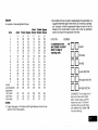
PRESET VALUES
Factory preset values serve two purposes:
●
They can reduce programming time on the part of the installer if many
of the preset values shown in the table are accepted.
. They will permit an installer who is unfamiliar with this product to
quickly set up the system for bench test so that familiarity with the
ooeration of the system can be achieved in a shorter period of time.
The factory preset values are defined in the Table that follows:
TABLE D. FACTORY
Factory Programmed
Address Function
00
INSTALLER CODE
01
MASTER
SECURITY CODE
02
ASSIGN
RESPONSE TYPE
FOR ZONES
1-8
Z1
Z2
Z3
Z4
25
Value
Elm EIEI
EEI EIEI
EHzI
EIEI
Elm
EIEI
IIIEI
Em
Em
Em
PROGRAMMING
Address Function
03
ASSIGN
RESPONSE
TYPE FOR
ZONES 9-16
04
ASSIGN
RESPONSE
TYPE FOR
ZONE 17
Fire
Perimeter, Burglary
Interior, Follower,
Burglary
by Day/Alarm
by Night, Burg.
Trouble
Interior,
Delay,
Burglary
Z6
27
Z8
24-hour
audible
24-hour
Aux
Entry/Exit
Burglary
(De!ay #1),
Factory Programmed
“EEI
“0Em
‘“EIEI
“2ElEl
“3Em
“4El El
‘“IZIEI
“6ElEl
“7El El
Em
Value
Address Function
Factory Programmed
❑
Value
m
EE
❑
m
HE
❑
m
IIlm
05
ASSIGN
RESPONSE TYPE
FORVARIOUS KEYPAD PANICS AND
ZONE EXPANDER
WIRING
SUPERVISION
‘EIEI
‘Elm
‘Em
‘Em
08
NOT USED
09
ENTRY DELAY #1
10
EXIT DELAY #1
III
III
““seconds)
III
m
“’seconds)
Factory Programmed
Address Function
11
ENTRY DELAY #2
12
EXIT DELAY #2
(90 seconds)
22
NOT USED
*
(120 seconds)
23
MULTIPLE
(8 minutes)
14
ALARM SOUNDER
SELECTION
(740/bell
15
KEYSWITCH ARM/DISARM ENABLE
(Disable)
CONFIRMATION
ARMING DING
(Disable)
17
18
19
20
21
OF
❑
o
NOT USED
DISABLE FIRE
TIME-OUT
25
DURESS REPORT
DISABLE (ADEMCO
HIGH SPEED)
26
INTERNAL ALARM
SOUND SELECTION
27
TEST REPORT
INTERVAL
28
POWER UP IN
PREVIOUS STATE
29
QUICK
(Entry of zero mandatory)
❑
❑
o
o
1
❑
❑
❑
❑
❑
o
(Enable)
o
(Enable)
o
(Loud steady sound,
UL Listed usage)
*
(24 hours)
1
ARM
1
(YES)
(Enabled)
•1
(Enable)
ALARM
DISABLE
NOT USED
TAMPER DETECTION
DISABLE
(ZONES 10-17)
(Disable)
AC POWER LOSS
SOUNDING
CONTROL
SOUNDER
compatibility)
24
30
TOUCH-TONE OR
ROTARY DIAL
❑
31
PABX ACCESS CODE
No Entry
32
SUBSCRIBER
ACCT No
(Entry of zero mandatory)
Value
(Yes)
ALARMS
n
ALARM SOUNDER
DURATION
4
Factory Programmed
Address Function
~
13
16
-
❑
❑
❑
Value
1
(Touch-Tone)
(No)
EIEHIIEIIIIEHIIEI
Address Function
Factory Programmed
33
PRIMARY PHONE No. No Entry
34
SECONDARY
PHONE No.
No Entry
35
CS DOWNLOAD
PHONE No.
No Entry
36
Value
6
Remote Arm enabled
7
Upload Program enabled
1
❑
CS ID No.
DOWNLOAD
COMMAND
ENABLES
❑
❑
❑
Value
1
8
mnm
EIEIIIIEI
IIIEIIIIEI
IIIEIEIEI
37
Factory Programmed
Address Function
1
Dialer Shutdown enabled
1
38
39
40
REPROGRAM I
DOWNLOAD
ATTEMPT REPORT
41
EOLR DISABLE
(Zones 2-8)
42
DIAL TONE PAUSE
43
DIAL TONE
DETECTION
System Shutdown enabled
3
❑
❑
n
Not Used
1
4
1
51
OPEN/CLOSE
REPORTING ENABLE
BY USER CODE
Remote Bypass enabled
Remote Disarm enabled
O
&n
(All non-fire zones
bypassable)
•mm~
•mm~~$’~d~~~
n
21 n
INHIBIT BYPASS
OF ZONE
Download Program enabled
❑❑
❑
❑o
❑
o
1
o
(No code reported)
(End-of-Line Resistor
superwsion not required)
(5 seconds)
1
(Dial Tone Detection
Enabled)
Address Function
44
45
46
47
48
49
Factory Programmed
RING DETECTION
COUNT
PRIMARY ACK WAIT
PRIMARY TRANSMISSION FORMAT
SECONDARY
WAIT
~
ACK
•1
o
SECONDARY TRANSMISSION FORMAT
o
❑
SINGLE MESSAGE
TRANSMISSION WITH
CHECKSUM
VERIFICATION
•1
o
50
SESCOA/RADIONICS
SELECTION
n o
51
DUAL REPORTING
o
Address Function
4+2 ZONE EXpANDED
FORMAT SELECTION
(30 seconds)
54
4+2 ZONE FORMAT
SELECTION
(Ademco
55
ALARM
56
RESTORE REPORT
$~~~~c’i”n
Low Speed)
(30 seconds)
OPEN/CLOSE
REPORTING ENABLE
BY USER CODE
❑
REPORT
❑o
❑o
o
❑
❑
❑o
1
(Ademco Low Speed)
57
BYPASS REPORT
(No)
58
TROUBLE
59
OPEN/CLOSE
REPORT
60
LOW BATTERY,
AC LOSS AND
TEST REPORT
61
CHANNEL
ASSIGNED TO
EACH ZONE
Radionics with B-F reporting.
(No)
n
52
Factory Programmed
53
IIlm
❑
❑o
Value
Dmm
REPORT
(Not selected)
(Not selected)
(Standard report)
(Expanded)
(Standard report)
o
•1
o
•1
(Standard report)
(Standard report)
1
2
•am~
(disabled for Users 2-8) –
Value
3
o
❑
o
❑
[Standard report)
I
0
Em
ml
.zerOeS for zones 1 -8
(no code reported)
FactoryProgrammedValue
Address Function
62
CHANNEL
ASSIGNED
EACH ZONE
(CONT’D)
‘o
‘Em
‘Em
‘Eml
‘Em
8EIEI
‘Em
Address Function
‘Elm
8EIEI
63
Zeroes for zones 9-16
(no code reported)
21111111
311HII
‘Em
5EIEI
‘EEl
CHANNEL
ASSIGNED TO
EACH ZONE
(CON’T)
3Elm
‘Em
‘Em
‘EHEl
700
•1
800
%
Factory Programmed
Address Function
64
CHANNELS
ASSIGNED TO
DURESS AND
VARIOUS KEYPAD
PANICS
1
2
3
4
5
6
Emil
EIEI
Emil
IZIEI
ImI
65
ALARM
REPORTING
CODES ASSIGNED
TO EACH
CHANNEL
‘mm
‘ED
3EEI
Factory Programmed
Address Function
4
5
6
All zeroes in 8 locations
(s%me as Address *61)
7
Duress
8
Short in Wiring to Zone
Expander (displays 97)
mm
Em
8EIEI
7
Value
1 & * panic
(displays 95)
3 & # Panic
(displays 96)
* & # Panic
(displays 99)
Zeroes for channels 1-8
(no code reported)
66
ALARM
REPORTING
CODES ASSIGNED
TO EACH
CHANNEL
(CONT’D)
9
10
Em
EIEI
Em
EIEI
Em
o ❑
o
❑
o
o ❑
•1
Zeroes for channels
9-15 (no code reported)
o o
•1
•1
‘2EHII
“mm
“EIEI
11
Value
Factory Programmed
Address Function
15
ValUe
EIEI
EIEI
Elm
EIEI
Em EIIII
Factory Programmed
Address Function
3
4
Not Used
67
NON-ALARM
CODES
66
NON-ALARM
CODES (CONT’D)
69
ZONE TYPES 1-4
RESTORE REPORT
mIl EIEI
ZONE TYPES 5-6
RESTORE REPORT
Zone 5
enabled, all
others disabled
71
ZONE TYPES 9&1 O
RESTORE REPORT
ENABLE
72
4+2 EXPANDED
FORMAT ZONES
1-8 EVENT DIGIT
(1s! digit)
6
All zeroes
(no codes reported)
Enable (all)
70
5
All zeroes
(no codes reported)
Em
Em
2EIEI
1
Enable (all)
AL
TR
Zeroes for
zones 1-8
(no codes)
reported
73
4+’ EXpANDED
FORMAT ZONES
9-16 EVENT DIGIT
(1st digit)
1
2
3
4
Value
IIHIIBY
IIHIIALRE
EIEITRRE
EHZIBYRE
EIEIAL
EIEITR
❑ ❑ ‘y
❑
Zeroes for
zones 9-16
(noCodes
AL RE reported)
m
EIEITRRE
6mIlBy
RE
5
Address Function
74
4+2 EXpANDED
FORMAT ZONE
17 EVENT DIGIT
(Ist digit)
Factory Programmed
Value
Address Function
1
Factory Programmed
5
lIlm
AL
EEITRRE
2
6
EmTR
EHIIBYRE
3
Zeroes for
zone 17
(noco,e~
EmBy
4
5
6
75
4+2 EXpANDED
FORMAT KEYPAD
PANICS/ZONE
EXPANDER
WIRING
SUPERVISORY
EVENT DIGIT
(Ist DIGIT)
1
2
3
4
Value
❑
A~RE
reported)
m
EHIZITRRE
EEIBYRE
EIEIAL
EIEITR
ElmBy
El El-AL
“
Zeroes for
keypad panics
and for zone
expander wiring
supervisory
(no codes
reported)
76
4+2 EXPANDED
FORMAT ZONES
1-8 ID DIGIT
(2nd digit)
1
III
El
2
Elm
3
EIEI
4
EIEI
5
EIEI
6
Elm
7
EIEI
8
EIEI
:~=~~~~~~;~’
Address Function
77
4+2 EXpANDED
FORMAT ZONES
9-16 ID DIGIT
(2nd digit)
Factory Programmed
Value
Address Function
‘El El :=~~~J~~~6
‘“EIEI
‘“ElEl
‘2EIEI
‘3Eml
“EHII
“EHII
‘6EIEI
78
4+2 EXPANDED
FORMAT ZONE
17 ID DIGIT
(2nd digit)
Factory Programmed
17
Value
III
Zeroes for zone 17
and the other seven
D,oca,ion,
III
Ill(nocodesrepo”ed)
EIEI
EIEI
Elm
EIEI
EIEI
Elm
Address Function
79
80
4+2 ExPANDED
FORMAT KEYPAD
PANICS/ZONE
EXPANDER WIRING
SUPERVISORY
ID DIGIT
(2nd digit)
4+2 EXPANDED
FORMAT NONALARM CODES
Factory Programmed
EIEI
EIEI
Elm
EIEI
Elm
Em
EIEI
EIEI
EIEI
EIEI
Value
Address Function
Duress
Short [n Wiring
to Zone Expander
1 & * panic
3 & # Panic
* & # Panic
Zeroes (no codes
reported) in all
10 locations
81
4+2 EXPANDED
FORMAT NONALARM CODES
(CON’T)
Factory Programmed
EIEI
Elm
Elm
ml
Elm
EIEI
Emil
Em
Elm
EIEI
Value
Zeroes (no codes
reported) In all
10 locations
Addrees Function
Factory Programmed
❑
Value
Address Function
84
m
85
IzllIl
❑
❑
86
m
ZONE EXPANDER
TYPE SELECTION
ENTRY WARNING
SELECTION
88
BURGLARY ALARM
COMMUNICATION
DELAY
89
ALARM VOLTAGE
TRIGGER OUTPUTS
lIl
m
ENABLE 5130XT
FOR SUBZONING
87
IIlm
❑
❑
ADEMCO HIGH SPEED
REPORTING ON
800/WATS LINES
Factory Programmed
n
~
•1
Value
o
(No)
o
(Disabled)
❑
o
❑
❑o
1
o
•1
(4208 type selected)
(three short beeps)
(no delay)
(zone expansion capabitliiy intact, no alarm
voltage triggers)
m
IIIKIl
82
ALARM
COUNT
(Swinger SuppressIon)
•~
83
TEST REPCRT
INITIATION TIME
❑❑
“2’0”’s)
mm
SPECIFIC
ADDRESS
PROGRAMMING
INSTRUCTIONS
ADDRESS
FUNCTION
INSTALLER
CODE
*OO
❑
oun
COMMENTS: This 4-digit (O-9) code reserved for installation company use. Only active if openings and closings
are enabled for User #1 (in Address *52), This is the only code that can be used to enter the Program mode from
the Control. Cannot be used to enter secondary codes. This code may not be used if programming mode is exited
by a ●98.
MASTER SECURITY
CODE
*O1
ASSIGN RESPONSE
TYPES FOR ZONES
*O2
1-8
❑
oun
COMMENTS.
feature.
❑
❑
❑
❑
❑
❑
❑
❑
❑
Enter 4 digits, O-9 (entry of all 4 IS mandatory).
0
Zonel
0
Zone2
0
Zone3
D
Zone4
n
Zone4
U
Zone5
o
Zone6
0
Zone j’*
0
.Zone8
Use of a “9
In last position Inhibits the Ambush
COMMENTS: Enter 2 dlglfs, 00-10 in each field
(use one of the response types below).
‘If Zone 7 is to be used for Keyswltch Arm/Disarm
operation, 10 must be entered as Its response type
00 =
01 =
02 =
03 =
04 =
05 =
06 =
07=
08=
09=
10 =
Assign for unused zones
ENTRY/EXIT (Delay #1), Burglary
ENTRY/EXIT (Delay #2), Burglary
PERIMETER, Burglary
INTERIOR, FOLLOWER, Burglary
TROUBLE BY DAY/ALARM BY NIGHT, Burglary
24-HOUR SILENT
24-HOUR AUDIBLE
24-HOUR AUXILIARY
FIRE
INTERIOR, DELAY, Burglary
FUNCTION
FUNCTION
ADDRESS
ASSIGN RESPONSE
TYPES FOR ZONES
9-16
*Q3
ADDRESS
lDn.Zcme!3
2UOZone10
30
UZonell
4UUZ...I2
5
❑
a
Zone13
6nUZcme14
,Ouzclnel,
i3UDZcme16
COMMENTS: Enter 2-digit response
types (see Address *O2 for types)
ASSIGN RESPONSE
TYPE FOR ZONE 17
*O4
1
❑
U
Zone17
mm
Jmzl
mm
5ED
Zeroes to be entered
ASSIGN RESPONSE
TYPES FOR ZONE
EXPANDER WIRING
SUPERVISORY
AND
FOR KEYPAD PANICS
*05
IIml
p
IFIl-q
mm
Zeros to be entered
4EM!ZI
LID
600
1 & * Panic (displays 95)
700
3 & # Panic (displays 96)
800
* & # Panic (displays 99)
COMMENTS: Enter response types
(See Address * 02 for types) in field
locations 5-8 only (enter 00 m
fields 1-4).
-.
FUNCTIC)N
DESIGNATE
RIGHT
ZONE USAGE
.——
——
--
ADDRESS
*O6
*O7
000
❑
Zone 17
n0 Onz”nes’o-”
COMMENTS: All spaces must be filled with O or 1 (1 if that zone is a right loop on a4190WH transponder or on a 4196
Quad PIR transponder). When the 4208 IS used as a Zone Expander, set all zone number locations to O. Stmilarly, se!
the zone number locations for 4139WH /41 94WH contact/transponders
and4192S0
smoke detector, 4275 Dual PIR
transponders to O, as well as left loops on 4190WHS and the PIR portion of the 4196.
NOT USED
*OS
ENTRY DELAY #1
*O9
rln
~~
COMMENTS: Defines the time period between a fault occurring in a zone to which Entry Delay #1 has been assigned
and the time when the alarm will sound (UL 1023 Household Burglary usage permits a maximum of 45 seconds), Applies to the Interior, Delay Zone type also,
Enter 00-15, Multiply by 15 seconds to determine time delay (O-225 seconds available).
EXIT DELAY #1
“o
•1
c1
COMMENTS: Defines the time delay period after the system
been assigned will arm (UL 1023 Household Burglary usage
time allocated to the Interior zones (both Follower and Delay
Enter 00-15. Multiply by 15 seconds to determine time delay
arming code is keyed when zone to which this delay has
permits a maximum of 60 seconds). Is also the exit delay
types).
(O-225 seconds available),
FUNCTION
ADDRESS
❑
ENTRY DELAY #2
*“•
COMMENTS: Defines the time period between a fault occurring in a zone to which Entry Delay #2 has been assigned
and the time when the alarm will sound. (UL 1023 Household Burglary usage permits a maximum of 45 seconds), Must
be set for longer period than Entry Delay #1 (in Address *09). Enter 00-15, Multiply by 15 seconds to determine
time delay (O-225 seconds available).
EXIT DELAY #2
*’2
•1
❑
COMMENTS: Defines the time delay period after the system arming code is keyed when zone to which this delay has
been assigned will arm, (UL 1023 Household Burglary usage permits a maximum of 60 seconds).
Must be set for longer period than Exit Delay #1 (in Address *1 O).
Enter 00-t 5. Multiply by 15 seconds to determine time delay (O-225 seconds available).
ALARM SOUNDER
DURATION
*’3
❑❑
COMMENTS: Defines the length of time an external or the control’s alarm sounder will sound for all audible alarms
(UL1 023 Household Burglary usage requires a minimum of 4 minutes).
Enter 01-15. Multlply by 2 minutes to determine sounder duration (2-30 minutes available)
ALARM SOUNDER
SELECTION
*I4
❑
COMMENTS: Enter O for Ademco 740 or BRK BK-PA400B piezoelectric
12V Motor Bell or for external relay activation, Do not enter “l”,
KEYSWITCH ARM/
DISARM ENABLE
*15
sounder, or AMSECO MSB-1 OG or ABB-1 031
❑
COMMENTS: Requires the use of zone 7 wired loop (zone 7 no longer available as protection zone when used for
keyswitch operation).
Enter 1 for keyswitch enable; otherwise, enter O.
NOTE: 10 must have been entered for Zone 7 in Address *02. Reports openings/closing
by user #7 if reporting IS
enabled in Address *52.
m
ADDRESS
FUNCTION
CONFIRMATION
OF
ARMING DING ENABLE
*16
❑
COMMENTS: Enter 1 to enable M second external alarm sounding at the end of exit delay #1 and O to disable the
“ding”,
AC POWER LOSS
SOUNDING
*17
❑
❑❑
❑
COMMENTS
NOT USED
*18
CONTROL
SOUNDER
ALARM
DISABLE
*19
Enter 1 to enable this feature. Results in rapid beeping at Control when AC power is lost; otherwise, enter O.
MUSTBEZERO
COMMENTS: Enter 1 to disable the built-in sounder at the control and remote consoles during a burglary: otherwise
enter O.
NOT USED
*2O
O
MfJST BE ZERO
•1
DISABLE
FIRE TIME-OUT
*21
•1
COMMENTS: Disables the sounder time-out fealure for any zone designated as a fire zone so that fire sounding continues until the system is reset (required for usage in accordance with UL985, Household Fire). Enter O (time-out) or 1
(no time-out),
NOT USED
.
*22
FUNCTION
MULTIPLE
ADDRESS
ALARMS
*23
❑
COMMENTS: Enables the system to permit multiple audible alarms from a protection zone during one armed Interval
(as opposed to only one alarm). Enter O (only one alarm) or 1 (multiple alarms, but not more frequently than allowed by
alarm time-out). Selection has no impact on the number of communication messages transmitted.
DISABLE TAMPER
DETECTION
IN EXPANSION ZONES 10-17
*24
n
~
COMMENTS: Only applicable if No.4190WH RPMs are used to provide expansion zones. Enter 1 to disable tamper
detection (disables tamper detection in 4190WH or tamper detection is not applicable because other devices are used
to provide expansion zones). Enter O to enable tamper detection (opening of the4190WH case),
DISABLE DURESS REPORTING IN ADEMCO
HIGH SPEED FORMAT
*26
❑
COMMENTS: Only applicable
enable duress reporting.
INTERNAL ALARM
SOUND SELECTION
*26
if Ademco High Speed Format is selected, Enter 1 to disable duress reporting or O to
❑
COMMENTS: Enter 1 to select a “sweeping” sound (applicable only to non-UL usage) from the control’s internal alarm
soundec enter O for a louder, steady sound (required for UL Listed usage).
NOTE: Since remote Consoles can only produce a “steady” sound, program the control for steady tone (0) if they are
used in the system.
TEST REPORT
INTERVAL
*27
COMMENTS: Determines time period between test reports. This setting also determines the interval between automatic
low battery tests under auxiliary current load with AC power disconnected. Even if test reporting is not desired, one of
the non-zero entries should be used. Enter O (no reporl), 1 (12 hours), 2 (24 hours) or3(168 hours).
Must be used in conjunction with Data Fields *83 and *68 (location 5) for test reporting.
FUNCTION
POWER UP IN
PREVIOUS STATE
ADDRESS
*28
❑
COMMENTS: If selected (YES), on power-up the system will assume system status prior to power down. If not selected
(NO), the system will power up in disarmed state.
Enter O (NO) or 1 (YES).
When the system powers up armed, an alarm will occur 3 minutes after arming if a zone is faulted. When so armed,
reports closing as User #7 if open/close reporting for User #7 was enabled in Address *52.
QUICK
ARM
*29
❑
COMMENTS: Enables arming of the burglary system in any mode without use of a Security Code (just # key depression
followed by the command AWAY, STAY, INSTANT or MAXIMUM). When armed AWAY or MAXIMUM, reports closing as
User #7 if open/close reporting for User #7 was enabled in Address *52. Enter O (disabled) or 1 (enabled).
TOUCH TONE OR
ROTARY DIAL
*3O
❑
COMMENTS: Permits selection of the type of dialing to be used.
Enter 1 for Touch-Tone, O for Rotary
PABX ACCESS
CODE
*31
❑o ❑l ❑0 ❑o
COMMENTS: If not required, enter nothing and proceed to next address; otherwise, enter prefix needed to obtain an
outside Telco line. This field may be used alternatively to enter a prefix that can suppress the Telco’s call waiting feaIure from interfering with outgoing transmissions. This prefix is only useful If the Telco option to be able to supress call
waiting has been obtained by your customer The prefix to be used is 1170 if pulse dialing is being used or *7O if
Touch-Tone dialing is being used,
Enler up to 4 digits, Each digit requires a 2-digit entry so as to allow entry of hexadecimal digits (B-F). Use the following
chart to determine the entry for each digit. Only enter digits required. Do not fill unused spaces. Erase the field by entering *31*.
FUNCTION
ADDRESS
NUMBER
SUBSCRIBER
ACCT. No.
*32
❑ o Elnml
o
1
2
3
4
5
6
7
ENTER
NUMBER
ENTER
00
01
02
03
04
05
06
07
8
9
A
B
c
D
E
F
06
(DO N%T USE)
11 or*
120r#
13
14
15
❑l
COMMENTS Enter 3 or 4 digits. Each digit requires a 2-digit entry so as to allow entry of hexadecimal
entry consists of only 3 digits, enter data in the first 6 locations, leaving the last two unfilled.
Use the chart in address *31 to determine the entry for each digit. Erase the field by entering *32*.
PRIMARY
PHONE No.
*33
COMMENTS: Enter up to 12 digits, 0-9. Do not fill unused spaces. Erase the field by entering *33*
NOTE: Back-up reporling (8 calls are made to the secondary phone number if no acknowledgment
attemDts to the orimarv number) is automatic only if there is a secondary phone number.
SECONDARY
PHONE No.
digits (B-F). If
is received after 8
*Tluclnonnclnucln
COMMENTS Enter up to 12 digits, O-9. Do not fill unused spaces. Erase the field by entering *34*. For UL (985/1 023)
Listed usage, it is required that the secondary phone number be different from the primary phone number.
CENTRAL STATION
DOWNLOAD
PHONE No.
*35nnclclnclnnnnnn
COMMENTS: Only applicable
the field by entering *35*,
if downloading
will be utilized. Enter up to 12 digits, 0-9. Do not fill unused spaces. Erase
FUNCTION
CENTRAL STATION
ID NUMBER
ADDRESS
*3’
❑
❑
o
COMMENTS:
n
Only applicable
❑
❑
0
if downloading
0
❑
0
❑
will be utihzed. Enter all 8 hexadecimal
n
❑
n
❑
n
digits (O-9, A-F).
OO=O06=611=B
01
=1
07=712=C
02=208
=813=D
03=3
09=914=E
04=410
=A15=F
05=5
DOWNLOAD
COMMAND ENABLES
*37
1
❑
Dialer Shutdown
System Shutdown
2
•1
3
4
5
6
7
8
❑
❑
❑
❑
❑
❑
Not Used
Remote Bypass
Remote Disarm
Remote Arm
Upload Program
Download Program
COMMENTS: Each of the various remote (from the Central Station) functions can
either be enabled or disabled, dependent upon what function~ the Central Station
desires to perform. Setting a function to be disabled means that the Central Station will not be able to perform this function in the system. Enter 1 to enable a
function and O to disable a function.
FUNCTION
ADDRESS
INHIBIT BYPASS
OF ZONE
*38
❑
n
COMMENTS: Enables one zone to be selected as a priority zone which cannot be bypassed. Enter 2 digits (for zone
number) 01-17. Enter 00 if all zones to be bypassabie, This selection has no impact on fire zones which are always
non-by passable.
OPEN/CLOSE
REPORTING ENABLE
BY USER CODE
USER#
9
10
11
12
13
14
15
*39
LHXICIUEII
COMMENTS: Enter O (disable) or 1 (enable), Determines which user codes will send open/close
REPORTING
CODE
FOR ATTEMPT
(SUCCESSFUL
OR
UNSUCCESSFUL)
BY
A REMOTE AGENCY
TO GET INTO A
DOWNLOAD MODE
WITH THE SYSTEM OR
FOR SOMEONE TO
LOCALLY CHANGE
THE PROGRAM.
*40
•1
c1
LOCAL REPROGRAM/DOWNLOAD
COMMENTS: Applicable
code reporting)
if downloading
reports,
ATTEMPT REPORT (1st digit)
will be utilized or not, Enter reporting code as double digits. Disable=
01=1
02=2
03=3
04=4
05=5
06=6
07=7
08=8
09=9
10=0
00 (no
ll=B
12=C
13= D
14=E
15=F
NOTE: If 4+2 by point reporting is being used, the second digit is the second digit of the power up code. (Field *81)
DISABLE USAGE
OF END-OF-LINE
RESISTOR SUPERVISION ON WIRED
ZONES 2-8
*4I
•1
COMMENTS: Enter 1 to change zones 2-8 to NC. loops that detect only an “open” and do not require end-of-line
tors (EOLRS). Enter O to retain EOLR supervision of zones 2-8,
Note
EOLR required
in a
UL installation.
resis-
ADDRESS
FUNCTION
DIAL TONE
PAUSE
*42
•1
COMMENTS: This feature determines the wait time for dial tone detection before dlalmg WIII commence
does not take place.
Enter single digit, O (5 seconds), 1 (11 seconds) or 2 (30 seconds).
DIAL TONE
DETECTION
*43
If detection
❑
COMMENTS: Determines whether true dial tone detection is used, or whether just delay before dialing (same as programmed in Address *42) is used, The latter may be necessary in high-noise environment Telco networks where noise
can be confused with dial lone and premature dialing resuhs.
Enter 1 (Dial Tone detection) or O (Dial Tone Detection disable),
RING DETECTION
COUNT
*44
•1
COMMENTS: Only applicable If central station initiated downloading will be used. Enter 00 to disable ring detection.
Enter 01-14 for ring counts of 1-14. Enter 15 to select mode that gets around telephone answering machines connected to the same phone line. In the latter mode, the system upon hearing one ring followed by nothing, will not
answer but will ready itself to pick up the next incoming call received wlfhin the next 30 seconds on the first ring (the
downloader calling again)
PRIMARY
ACK WAIT
*45
❑
COMMENTS: Central Station receiver “Acknowledge”
Enter O (30 seconds) or 1 (60 seconds).
wait time for primary phone number,
FUNCTION
ADDRESS
PRIMARY TRANSMISSION FORMAT
*46
❑
COMMENTS: Permits selection between Ademco Low Speed format, SESCOA/Radionics,
or Ademco High Speed
format.
Enter O (Ademco Low Speed), 1 (SESCOA/Radionics),
or 2 [Ademco High Speed — Traditional for up to 15 (all 20 if
non-unique reporting is acceptable) zones plus duress and 4+2 DTMF for all 21 zones].
NOTE: If Traditional Ademco High Speed reporting is selected, the Non-Alarm reports desired must be selected in
Addresses *40, *67 and *66 and the alarm reports desired must be selected in Addresses *65 and *66.
SECONDARY
WAIT
ACK
*47
•1
COMMENTS: Central station receiver “Acknowledge” wait time for secondary phone number.
Enter O (30 seconds) or 1 (60 seconds).
SECONDARY TRANSMISSION FORMAT
*48
❑
COMMENTS: Same options as Address *46.
Enter O (Ademco Low Speed), 1 (SESCOA/Radionics),
SINGLE MESSAGE
TRANSMISSION
WITH
CHECKSUM
VERIFICATION
*49
SESCOA/RADIONICS
SELECTION
*5O
or 2 (Ademco High Speed).
•1
COMMENTS: When selected, will send a verification digit with the message to validate the message at the receiver
without having to send two message rounds. Enter O (NO) or 1 (YES).
NOTE: Selection applies to both primary and secondary phone numbers,
•1
COMMENTS: Enter O if Radionics format is to be used with hexadecimal O-9, B-F reporting; enter 1 if SESCOA format is
to be used with only numeric reporting (0-9).
NOTE: Selection applles to both primary and secondary phone numbers.
FUNCTION
ADDRESS
DUAL REPORTING
*51
❑
COMMENTS: If selected, will send all reports to both primary and secondary phone numbers.
NOTE: If dual reporting is desired and Ademco High Speed format is to be used at all, it must be selected as both the
primary and secondary transmission formats
Enter O (NO) or 1 (YES)
OPEN/CLOSE
REPORTING ENABLE
BY USER CODE
USER
*52
‘Iimlnnuurl
COMMENTS: Enter O (disable) or 1 (enable) Determines which user code will send open/close reports. User #7 must
be enabled if open/close reporting is desired for keyswitch arming or close reporting E desired for ‘“Quick Arm” and
‘(Power Up” arm.
NOTE: User #1 must be enabled to permit use of installer code to enter Programmmg mode.
4+2 ZONE (MAX. OF 17
WIRED ZONES)
EXPANDED FORMAT
SELECTION
*53
4+2 ZONE (MAX. OF
9 WIRED ZONES)
FORMAT SELECTION
*54
❑
COMMENTS: Enter 1, if 4+2 reporting by zone for a zone expanded system is desired, enter O if a non expanded zone
configuration is being used. If the expanded zone reporting format IS selected, skip Addresses 55-71 and continue programming at Address #72.
IMPORTANT
If Ademco High Speed format had been selected in Addresses *46 or *48 and this selection is made, a
high speed 4+2 transmission using DTMF Touch Tone communication can be obtained which is compatible with
Ademco No. 685 Digital Receivers using Level 4.3 software or higher.
•1
COMMENTS: Enter 1,if 4+2 reporting E desired, enter O if 3+1 /4+1 or traditional Ademco High Speed reporhng is to be
used. This selection is overridden by the selection of 4+2 reporting in Address *53. If the 3+1 /4+1 /4+2 format of address
*54 is selected, Address 55-70 should be programmed, but Addresses 72 through 81 should be skipped.
The following reports (Addresses *55-*60)
may be designated to report either in Standard or Expanded format. in aii cases, the Standard message
reports to the centrai station a subscriber iD number and a report (e.g., aiarm [see Address *55], troubie, restore, opan/ciose) code. The Expanded
message reports a subscriber iD number, the reportcode,foiiowedby a second iine where the report code is repeated three or four times and is
traiied bv the channei number for user iD) reiated to that renorf. When 4+2 format is seiected. no second iine is transmitted. The channei number or
User iD k sent es the iast digi; of the report.
Report
3+jj4+f
Standard
3+j~4+l
Expanded
Alarm
SSS(S) A
SSS(S) A
4+2
SSSS ACh
Repoh
3+1/4+1
Standard
3+ji4+j
Expanded
AC LOSS
SSS(S) R
SSS(S) R
AAA(A) Ch
Trouble
SSS(S) T
~(T)
Bypass
Sss(s) B
Low Battery
SSS(S) R
LOSS
SSS(S) E
SSS(S) E
Trouble
SSS(S) RT
SSS(S)RT
SSSS RTCh
SSSS EAC
Bypass
SSS(S) RB
RTRTRT(RT)Ch
SSS(S)RB
SSSS RBCh
flBRBRB(flB)Ch
EEE(E) Ac
Low Battery
SSS(S) L
SSSS LLB
SSS(S) L
LLL(L) LB
Open
Sss(s) o
Ssss
Sss(s) o
000(0)
Close
Sss(s) c
Ou
u
Ssss
Sss(s) c
ccc(c)
SSSS RLB
SSSS 6ch
BBB(B) Ch
AC
SSS(S) R
RRR(R) LB
Ch
SSS(S) B
SSSS RAG
RRR(R) AC
SSSS Tch
SSS(S) T
4+2
Cu
u
Where:
SSS or SSSS = Subscriber ID
A = Alarm Code
L = Low Battery Code (1s! digit)
LB = Low Battery Code (2nd digit)
O = Zero
Ch = Channel Number
O = Open Code
C = Close Code
T = Trouble Code
B = Bypass Code
U = User Number
Te = Test Code
R = Restore Code (Alarm,
AC Loss, Low Battery)
Cancel
Sss(s) x
Sss(s) x
Ssss Xo
Test
SSS(S) Te
SSS(S) Te
SSSS TeO
E = AC Loss Code (1st Digit)
Ac = AC Loss Code (2nd digit)
Power Up Reset
Sss(s) P
Sss(s)
Ssss Po
X = Cancel C?de
RT = Restore Code (Trouble)
Program Tamper
SSS(S) M
SSS(S) M
SSSS MO
P = Power Up Reset Code
RB = Restore Code (Bypass)
SSS(S) R
Sss(s)
SSSS Rch
P
Rester=
Alarm
M = Program Tamper Code
R
RRR(R) Ch
Ademco High Speed Format
This format is the fastest format used in the alarm industry in that alarm
information on 8 zones can be received at a Central Station in 5 seconds.
This format utilizes DTMF (Touch-Tone) signaling and transmits at the rate
of 10 hexadecimal
characters per second. The traditional format of
Ademco High Speed transmission contains 13 digits, as follows: 4 digit
Subscriber ID number, 8 digits containing the status of each of 8 event
reporting channels and 1 digit in a 9th channel that is primarily used to
indicate what kind of event is being received in the other 8 channels.
For the eight event reporting channels
channel status codes are as follows:
Code
1
2
3
4
5
6
(digits 5-12 in the format), the
Meaning
NEW EVENT (previously unreported)
OPENING REPORT
RESTORE
CLOSING REPORT
NORMAL (no event since previously reported RESTORE)
PREVIOUSLY REPORTED EVENT STILL PRESENT
For the ninth channel (digit 13), the following
used:
channel status codes are
1 DURESS REPORT in channel 1 and ZONE ALARM and ALARM RESTORES assigned to CHANNELS 9 through 15 (in Addresses *61
through *64) will appear in channels 2 through 8
2 OPENING REPORT in the previous 7 or 8 channels; 7 if expanded
opening/closing
reporting is selected, wherein User ID (1 -9, A-F)
appears in Channel 1.
3 BYPASS and BYPASS RESTORE REPORTS for ZONES assigned to
CHANNELS 1 through 8 (in Addresses *61 through *64) will a~pear in
Channels 1 through 8.
4 CLOSING REPORT in the previous 7 or 8 channels; 7 if expanded
opening/closing
reporting is selected, wherein User ID (1 -9, A-F)
appears in Channel 1.
5 ZONE TROUBLE and TROUBLE RESTORE REPORTS for ZONES
assigned to CHANNELS 1 through 8 (in Addresses *61 through *64)
will appear in channels 1 through 8.
6 SYSTEM TROUBLE and TROUBLE
previous 8 channels; wherein:
CH
CH
CH
CH
*No
1 = LOSS of AC
2 = Low Battery
3 = Program Tamper*
4 = Power On Reset*
Restore report is provided for
RESTORE REPORTS are in the
CH 5 = Not Applicable
CH 6 = Not Applicable
CH 7 = Not Applicable
CH 8 = Not Applicable
these conditions,
7 ZONE ALARM and ALARM RESTORE REPORTS for ZONES assigned
to CHANNELS 1 through 8 (in Addresses *61 through *64) will appear
in channels 1 through &
9 TEST REPORT. All ‘5’s will appear in channels 1 through 8,
lmDortant Notes
1, When the traditional Ademco High Speed format is used, zones
assigned to channels 9 through 15 in Addresses *61 through *64
cannot report trouble, trouble restore, bypass, and bypass restore. As
such, 24 hour type keypad panic zones are good candidates for the use
of these reporting channels (e.g. * &#, 1 & *, 3 & # panics, etc...)
2 Only NEW events: ALARM, OPENING, RESTORE, BYPASS, CLOSING
or TROUBLE on any channel or TEST will trigger transmission, at which
time all 9 channels will report.
3 When the traditional Ademco High Speed format is used, non-zero
codes must be entered in Addresses 61,62,63,64 (for zones in use), 65,
66, 67 and 68.
Examples (Ademco
1.
High Speed Zone format)
Subscrlbsr
Identification
Message:
Channel Number
123456789
5890
Channel 2:
Channel 5:
Channel 6:
2.
After transmission
Message:
Message:
5890
Channel 2:
Channels 5,6:
535566557
NEW RESTORE
PREVIOUSLY REPORTED ALARMS
(still in effect)
Subscriber #0135 sends an opening:
Subscriber
Identification
Message:
0135
Channel 1:
Channels 2-9:
0135
Channel 1:
Channels 2-9:
5.
Subecrlber
Identification
Message:
0135
Channel 1:
Channel 9:
6.
122222222
USER lD-User #1 opened
OPENING REPORT TRANSMITTED
D44444444
USER lD-User #13(= hex D) closed
CLOSING REPORT TRANSMITTED
Channel Numbar
123456789
155555551
DURESS REPORT
SUPPLEMENTAL ALARM ZONES
TRANSMITTED
Subscriber #0135 User #7 bypasses faulted zone 2 (for the sake of this
example, Zone 2 = Channel 3, not a requisite) and then arms the
system.
Subscriber
Identification
Message:
0135
0135
Channel Number
f23456769
Channel Number
123456789
Subscriber #0135 sends a duress message:
Still at subscriber #5890, following the events of example 1 above,
channel 2 restores (initiating the call) and channels 5 and 6 remain in
alarm:
Channel Number
123456769
of Example 3, subscriber #0135 sends a closing:
Subscriber
Identiflcatlon
515516557
NEW ALARM
NEW ALARM
PREVIOUSLY REPORTED ALARM
(still in effect)
Subscriber
Identiflcatlon
3.
4.
At subscriber #5890, channels 2 and 5 go into alarm (and initiate a call)
and channel 6, which has previously reported an alarm is still triggered.
Bypass restorals are transmitted
0135
Channel Number
123456789
551555553
744444444
when the restoral takes place
553555553
7.
If a trouble condition occurs in Zone 4 for subscriber #589rJ and Zone 4
wasassigned to Channel 2, a trouble report is transmitted.
Subscriber
Identification
Message:
Channel Number
123456789
5890
5890
occurs, a separate
Subecrlber
Identification
Message:
trouble message
Channel Number
123456789
For Lossof AC Reporfing(Channell
is used)
0135
155555556
0135
Message
Message
Message:
515555556
Restoral
0135
Message:
FUNCTION
REPORT
535555556
0135
5551
55556
to Program Tamper and Power Up
5890
555351551
10. At Subscriber #0135 a test message is initiated,
Sutmcrlber
Identification
355555556
(Channel 2 IS used)’
0135
For Low Battery
ALARM
Reporting
551555556
9, At Subscriber #5890, zone 12 assigned to channel 13 goes into alarm
and zone 11 assigned to channel 11 which has previously reported an
alarm, has restored.
Channel Number
Subscriber
Identification
123456789
‘For AC Restoral
For Low Battery
0135
For Power Up Reset (Channel 4 is used)
Note Restorals are not applicable
Reset,
535555555
If a system trouble condition
format exists,
Message:
Message:
515555555
Trouble restoral is transmitted as soon as it occurs,
8.
For Program Tamper (Channel 3 is used)
Message:
0135
Channel Number
123456769
555555559
●Low battery is only determined when AC power is oft and the battery is
being discharged. It is also tested for by periodically (at the interval
selected in Address #27) removing ACpower briefly to check battery
status.
ADDRESS
*55
❑
COMMENTS: Enter O (Standard Report) or 1 (Expanded Report),
When Expanded is selected, the channel number is transmitted in the last position of the 2nd transmission
the 1st transmission line if 4+2 Format is used), Zone ID is not transmitted.
NOTE: Selection applies to both primary and secondary phone numbers,
line (or of
FUNCTION
RESTORE
ADDRESS
REPORT
*56
❑
COMMENTS: Enter O (Standard Report) or 1 (Expanded Report).
When a zone of protection alarm, bypass or trouble report ts transmitted, a restore report for any of those conditions is
not issued unless ALL Iike conditions within azone are restored.
When Expanded is selecfed, the channel number is transmitted in the last position of the 2nd transmission line (of the
1st transmission line if 4+2 Format is used). Restore reports for each zone type alarm are individually selectable (see
Address numbers *69 through *7 I ). Zone ID is not transmitted.
NOTE: Selection applies to both primary and secondary phone numbers.
BYPASS REPORT
*57
•1
COMMENTS: Enter O (Standard Report) or 1 (Expanded Report).
Bypassing azoneresults
inabypass
report and inarestore
report when all bypasses are removed,
Fire and priority zones cannot be bypassed. When Expanded is selected, the channel is transmitted in the last position
of the 2nd transmission line (or of fhe 1st transmission line if 4+2 Format is used). Zone ID is not transmitted.
NOTE: Selection applies to both primary and secondary phone numbers.
TROUBLE
REPORT
*58
n
COMMENTS: Enter O (Standard Report) or 1 (Expanded Report).
When Expanded is selected, the channel is transmitted in the last position of the 2nd transmission
transmission line if 4+2 Format is used). Zone ID is not transmitted.
NOTE: Selection applies fo both primary and secondary phone numbers.
OPEN/CLOSE
REPORT
*59
line (or of the 1st
❑
COMMENTS: Enter O (Standard Repoti) or 1 (Expanded Report).
When Expanded is selecfed, user ID (1 -9, A-F) is fransmJted in the last position of the 2nd transmission
1st transmission line if 4 + 2 Format is used),
NOTE: Selection applies to both primary and secondary phone numbers.
line (or of the
m
FUNCTION
ADDRESS
FUNCTION
LOW BATTERY
AC LOSS AND
TEST REPORT
ADDRESS
❑
*6O
‘nnzone’
‘Clnzone’
COMMENTS: Enter O (Standard Report) or 1
(Expanded Report).
When Expanded is selected, an additional
programmable code is transmitted in the
last position of the 2nd transmission line (of
the 1st transmission line if 4 + 2 Format is
used.)
NOTE: Selection applies to both primary
and secondary phone numbers.
CHANNEL
ASSIGNED
1
LUNG
TO
*6’
‘n
2
I3
❑
❑
‘one’
‘0ne2
‘Elcl zone’
‘Llnzone’
‘Elnzone’
‘nclzone’
COMMENTS: Enter all channel IDs as
double digits. Disable =00 (no channel
reporting)
01=1
02=2
03=3
04=4
05=5
CHANNEL
ASSIGNED
TO
EACH ZONE
(CON’T)
*62
‘n
‘no
06=6
07=7
08=8
09=9
10=0
❑
ll=B
12=C
13=D
14=E
15=F
‘one’
‘one’o
‘no ‘one”
‘no ‘One’2
‘on ‘one”
‘El ❑ ‘one”
FUNCTION
ADDRESS
FUNCTION
‘ml ‘one”
‘no ‘one”
COMMENTS: Enter all channel IDs as
double dlglts (same as Address *61). Disable =00 (no channel reporting),
CHANNEL
ASSIGNED
TO
EACH ZONE
(CON’T)
*’3
‘cl
❑
‘0””7
‘m
III
‘“’used
3EIEl ‘“’used
‘El III ‘“’used
‘El ❑ ‘“’used
‘El El ‘“’used
‘El El ‘otused
‘m
❑
‘“tUsed
ADDRESS
COMMENTS: Enter all channel IDs as
double digits (Same as Address *61).
Disable =00 (no channel reporting)
CHANNEL
ASSIGNED
TO
EACH ZONE
(CON’T)
‘“
‘•
‘mm
❑
‘“’used
‘“’used
‘El El ‘otused
‘n ❑ ‘Uress
‘Eln’&*’anic
‘cm “’panic
‘Cln “’panic
COMMENTS: Enter all channel IDs as
double digits (same as Address *6 I ). Disable = 00 (no channel reporting).
NOTE: Non-zero codes must be entered
when traditional Ademco High Speed format is used.
m
FUNCTION
ALARM REPORTING CODES
ASSIGNED
TO
EACH CHANNEL
ADDRESS
*’5
FUNCTION
ALARM REPORTING CODES
ASSIGNED
TO
EACH CHANNEL
’00
ADDRESS
*“
‘nn
‘On
‘OOOO
300
‘Eln
‘no
’00
‘on
‘no
“00,
“ED
“nlm
“LID
“no,
ElEl
COMMENTS: Enter all alarm reporting
codes as double digits, Disable = 00 (no
code reporting)
01=1
02=2
03=3
04=4
05=5
06=6
07=7
08=8
09=9
10=0
II=B
12=C
13=D
14=E
15=F
NOTE: Non-zero codes must be entered
when traditional Ademco High Speed format is used.
‘otused
COMMENTS: Enter all alarm reporting
codes as double digits (same as Address
*65),
Disable =00 (no code reporting),
NOTE: Non-zero codes must be entered
when traditional Ademco High Speed format is used.
FUNCTION
NON-ALARM
CODES
FUNCTION
ADDRESS
*67
❑❑
❑
❑
❑
❑
❑
❑
n
n
n
n
n
n
AC LOSS
AC LOSS 2nd DIGIT
TROUBLE
TROUBLE RESTORE
BYPASS
BYPASS RESTORE
RESTORE CODE FOR
ALARM, AC, LOW
BATTERY
COMMENTS: Enter all codes as double
digits (see Address *65).
Disable =00 (no report).
NOTE: Non-zero codes must be entered
when traditional Ademco High Speed format is used.
NON-ALARM
CODES
*’8 ❑ ❑ ‘PEN
❑ ❑ cLOsE
ADDRESS
❑
❑❑
❑❑
❑❑
❑❑
❑
n
n
LOW BATTERY
LOW BATTERY
2ndD1G1T
‘TEST
*pOwERupl
‘OTusED
‘CANCEL
CODEZ
COMMENTS: Enter all codes as double
digits (see Address *65)
Disable =00 (no report),
NOTE: Non-zero codes must be entered
when traditional Ademco High Speed format is used.
* When 4+2 by zone (field 54) format is
used, the 2nd digit of the event code is
always “O”
NOTES
1. After a power reset, or after exiting the Program mode, this code will be
sent.
2. If system E shut down by using a security code while a burglary alarm is
sounding, this code will be sent. (Not sent for 24-hour zones.)
‘CancP1 in traditional Ademco High Speed format ISthe same as
an Opening Report for user 15 and should not be used together.
m
FUNCTION
ADDRESS
To disable Restore reports,
as Lt.
ZONE TYPES 1-4
RESTORE
REPORT
ENABLE
INTRODUCTION
program
all locations
in Addrasaea
*69-71
*69
types),
COMMENTS: Enables Restore reponing for
individual zone types. Enter 1 to select restore reporting for the zone type; enter O to
inhibit restore reports.
ZONE TYPES 5-8
RESTORE
REPORT
ENABLE
types). ”
*71
ADDRESSES
72-81
Bearing in mind that a 2 digit reporting code is utilized, let us discuss how
zones 1-17, Duress, Zone Expander Supervisory, and the 3 keypad panics
(1 &*,3&#,
and * &#) can be coded. The recurring theme of the following information is that the leading digit represents the type of event being
reported and the second digit identifies the zone within that type,
NOTES:
1, Two digit entries are requmed because hexadecimal entries are allowed
(O-9, B-F) = (00-15) for fields 72-81.
2. Users of the Ademco CAPS Automation System are cautioned not to
assign 78 or 8C for any report, as these codes are reserved.
*7O
COMMENTS: Enables Restore reporting for
individual zone types. Enter 1 to select restore reporting for the Zone type; enter O to
inhibit restore reports.
ZONE TYPES 9
AND 10 RESTORE
REPORT
ENABLE
TO FIELD
In order to make it easier for an installer to understand expanded zone
reporting, an explanation and an illustrative example are given first.
9
❑
10
u
(See Address *O2
for Response types)
COMMENTS: Enables Restore reporting for
individual zone types. Enter 1 to select restore reporting for the zone type enter O to
inhibit restore reports,
3. If Ademco High Speed Format is selected in either Addresses *46 or
*48 and the 4+2 Expanded Zone Format is selected m Address *53,
a very fast 4+2 Format is created that uses DTMF (Touch-Tone) slgnalIing instead of pulses, Actually, 9 digits are transmitted but only the 4+2
portion of the message is ever seen on the central station receiver’s
display or printer. This High Speed 4+2 format is currently only compatible with Ademco No. 685 Digital Receiver operating with Revision 4.3
software or higher and has a message transmission time of well under
5 seconds.
Example
An example of code assignments
Zone
;
3
4
5
6
7
8
9
10
11
12
13
14
15
16
17
Duress
Zone Expander
Supervisory
1 & * panic
3 & # Panic
* &# Panic
11
12
13
14
15
16
17
19
21
22
23
24
25
26
27
28
10
29
2B
follows:
Trouble
Bypass
31
32
33
34
35
36
37
39
41
42
43
44
45
46
47
48
30
49
4B
51
52
53
54
55
56
57
59
61
62
63
64
65
66
67
68
50
69
5B
Alarm Trouble
Reetore Restore
71
72
73
74
75
76
77
79
81
82
83
84
85
86
87
88
70
89
8B
91
92
93
94
95
96
97
99
01
02
03
04
05
06
07
08
90
09
OB
Bypass
Restore
D1
D2
D3
D4
D5
D6
D7
D9
El
E2
E3
E4
E5
E6
E7
E8
DO
E9
EB
5. Note that B and Care not used for leading digits in the above table. It is
suggested that these digits be reserved for use in reporting “openings”
and “closings” so that the appropriate display and print out can be
obtained at the central station receiver and so that an automation
system can be given the appropriate information.
FUNCTION
ADDRESS
4+2 ExPANDED FORMAT ZONES 1-8 EVENT
DIGIT (Ist digit Of
raporting code)
*72
❑❑
❑❑
❑ EIBYPASS
❑o
❑
❑
IALARM
ITROUBLE
ALARM RESTORE
n
n
2D
2E
2F
4D
4E
4F
5D
5E
5F
8D
8E
8F
OD
OE
OF
ED
EE
EF
NOTES
4 English language on the Ademco 685 Digital Receiver should not be
us=d for m~st o~ these reports.
TROUBLE RESTORE
BYPASS RESTORE
““
COMMENTS: The first digit of the 2
digit event code used to report
alarm, trouble, bypass, and their
restores for zones 1-8. Enter all
reporting codes as double digits
(see Address *65). Disable =00
(no code reporting).
FUNCTION
ADDRESS
4+2 EXPANDED FORMAT ZONES 9-16
EVENT DIGIT (lst digit
of reporting code)
*73
FUNCTION
•1
Il.,.
❑❑
❑ ❑✍
ITROUBLE
III
❑
❑
ALARM RESTORE
o
TROUBLE RESTORE
BYPASS RESTORE
n
COMMENTS: The first digit of the 2
digit event code used to report
alarm, trouble, bypass, and their
restores for zones 9-16, Enter all
reporting codes as double digits
(see Address *65). Disable =00
(no code reporting).
4+2 EXPANDED FOR.
MAT ZONE 17 EVENT
DIGIT (Ist digit of
reporting code)
ADDRESS
*74
❑❑
❑❑
El ❑ y,.ss
❑0
❑0
❑o
ALARM
ITROUBLE
ALARM RESTORE
TROUBLE RESTORE
BYPASS RESTORE
COMMENTS: The first digit of the 2
digit event code used to report
alarm, trouble, bypass, and their
restores for zone 17 Enter the
reporting code as double digit
(see Address *65). Disable =00
(no code reporting).
FUNCTION
FUNCTION
ADDRESS
4+2 EXPANDED FORMAT KEYPAD PANICS/
ZONE EXPANDER
WIRING SUPERVISORY
EVENT DIGIT
(lst digit of
reporting code)
*75
❑❑
❑❑
❑❑
❑
❑0
❑o
n
ALARM
4+2 EXPANDED FORMAT ZONES 1-8 ID
DIGIT (2nd digit of
reporting code)
ADDRESS
*7’
“
TROUBLE
’200
BYPASS
’300
ALARM RESTORE
TROUBLE RESTORE
BYPASS RESTORE
COMMENTS: The first digit of the 2
digit event code used to report
alarm, trouble, bypass, and their
restores for various keypad panics
(duress, * &#, 1 &*, and 3 & #)
and for supervision of the wiring
(for short circuits) to the zone
expander. Enter all reporting codes
as double digits (see Address *65).
Disable = 00 (no code reporting).
❑❑
“no
“no
‘mu
“no
“no
COMMENTS: The first digit of the 2
digit event code used to report
alarm, trouble, bypass, and their
restores for zone 17. Enter the
reporting code as a double digit
(see Address *65). Disable =00
(no code reporting).
FUNCTION
ADDRESS
4+2 EXPANDED FORMAT ZONES 9-16 ID
DIGIT (2nd digit of
reporting code)
*77
FUNCTION
ADDRESS
❑
“0 ❑ o
‘“ ❑ o
“
Em
I ‘eroestobeentered
EmI
Em
E!u!zl
n
“2 cm
’13❑ 0
❑m
“4 ❑ o
‘“ ❑ o
‘“ ❑ o
COMMENTS: The second digit of
the 2 digit event code used to
report alarm, trouble, bypass, and
their restores for zones 9-16. Enter
all reporhng codes as double digits
(see Address *65). Disable =00
(no code reporting).
4+2 EXPANDED FORMAT ZONE 17 ID
DIGIT (2nd digit of
reporting code)
*78
’17
❑
n
Em
IImI
COMMENTS: The second digit of
the 2 digit event code used to
report alarm, trouble, bypass, and
their restores for zones 17 Enter
the reporting code as a double digit (see Address *65) In the ftrst
field location (enter 00 in the other
seven fields). Disable = 00 (no
code reporting).
4+2 EXPANDED
FORMAT KEYPAD
PANICSIZONE
EXPANDER WIRING
SUPERVISORY
ID
DIGIT (2nd digit
of repo-hing code
*79
Ellzl
Emil
Eml
Zeroes to be entered
❑o
❑o
Duress
Short in Wiring to
Zone Expander
FUNCTION
FUNCTION
ADDRESS
o
3 & # Panic
❑l
❑
n
* & # Panic
On
1 & * panic
nn
❑
❑
COMMENTS: The second digit of
the 2 digit event code used to
report alarm, trouble, bypass and
their restores for various keypad
panics (duress, * &#, 1 &*, and 3
& #) and for supervision of the wiring (for short circuits) to the zone
expander. Enter all reporting
codes as double digits (see
Address *65). Disable =00 (no
code
reporting).
4+2 EXPANDED
FORMAT NON-ALARM
CODES
**O
❑
❑
❑
❑
❑
ADDRESS
n
CLOSE REPORT (1st digit)
0
CLOSE REPORT (2nd digit)
n
OPEN REPORT (1st digit)
o
OPEN REPORT (2nd digit)
n
LOW BATT REPORT (1st digit)
n
❑
❑
LOW BATT REPORT
(2nd digit)
LOW BATT RESTORE
REPORT (1st digit)
LOW BATT RESTORE
REPORT (2nd digit)
n
TEST REPORT (1st digit)
O
TEST REPORT (2nd digit)
COMMENTS:
. Enter all reporting codes as double digits (see Address *65).
Disable =00 (no code reporting) if both 1st and 2nd digits are
so programmed.
ReDort
must be C (hex 12) if English Printout of
“clos~’ is desired on Ademco No, 6’85 Receiver of if closing by
user is to be processed on an Ademco Automation System
● 1st digit of Open Report must be B (hex 11) if English printout of
“open” is desired on Ademco No. 685 Receiver or if opening by
user is to be processed on an Ademco Automation System.
. The 2nd digit of both the Close and Open Reports represents
the user ID for the Installation Company Security Code. User
No. 2 is automatically assigned an ID one higher than this code
(e.g., if 01 is keyed, User 2 reports as 2, User 3 as 3, etc...)
.
1 st dicrit of Close
FUNCTION
ADDRESS
4+2 EXPANDED FORMAT NON-ALARM
EVENT CODES (Cent’d)
❑❑
❑
❑ EI
*8’
0
tln
POWER UP REPORT (1st dlgtt)
POWER UP/DOWNLOAD
ATTEMPT REPORT (2nd digit)
AC LOSS REPORT (1 st digit)
AC LOSS REPORT (2nd digit)
❑o
no
❑
❑u
❑
❑o
AC RESTORE REPORT (1 st digit)
AC RESTORE REPORT (2nd digit)
O
Not “~~d – z~r~e~to be En@~~(j
0
Not used – Zeroes to be Entered
o
n
CANCEL REPORT (1st dlglt)
CANCEL REPORT (2nd digit)
COMMENTS:
Power Up is transmitted after a power reset or after exiting the Program Mode.
. Cancel is transmitted if system is shut down while a burglary alarm is sounding.
● Enter all reporting codes as double digits (see Address *65). Disable = 00 (no code reporting) if both Ist and 2nd
digits are so programmed,
●
FUNCTION
ALARM
ADDRESS
COUNT
*82
❑l
COMMENTS: Enter 01-15.
This option limits the number of messages (Alarms or Troubles) sent for a specific channel in an armed period
(Swinger Suppression) before additional reports from that channel are inhibited. This selection is system-wide.
TEST REPORT
INITIATION TIME
*83ml
~~
COMMENTS: Enter the time in hours from the time that the programming mode is exited that the first test report shall be
transmitted. 00 entry signifies immediately upon exiting. 01-31 represents the range in hours that can be selected,
ADEMCO HIGH SPEED
FORMAT USED ON
WATS LINES
*84
•1
COMMENTS: Enter 1 if Ademco High Speed Format (either traditional or 4+2 versions) will be transmitted on
800/WATS lines where satellite links may be used. Enter O if other formats are selected or if local telco lines are being
used.
DO NOT USE
*85
•1
ZONE EXPANDER
TYPE SELECTION
o
MUST BE 2ER0
*88
•1
COMMENTS: Enter 1 if No. 4208 Eight Zone Expander is being used. Enter O if other VECTOR type RPMs are being
used to expand the number of zones.
Important See the section on an earlier page (Zone Expansion) for proper configuration of the No. 4208.
FUNCTION
ADDRESS
ENTRY WARNING
SELECTION
*87
•1
COMMENTS:
BURGLAR ALARM
COMMUNICATION
DELAY
Enter O for three short beeps, or 1 for slow continuous
*88
•1
COMMENTS: Enter O for no delay on communication,
no delay on 24-hour reports).
ALARM VOLTAGE
TRIGGER OUTPUTS
beeps throughout the entire entry delay period.
*89
or
1 for 16-second delay on burglary alarm communciation
(wkh
❑
COMMENTS: Set to O (zone expansion capability intact, no alarm voltage trigger) or 1 (zone expansion capability
suppressed, alarm voltage triggers active) .See Diagram 4foralarm
voltage trigger outputs on digital communication
board.
PROGRAMMING
ZONE DESCRIPTIONS
An appropriate description/location
for each protection zone can be programmed into the system. Each description maybe composed of a combination of words (up to a maximum of 3) that can be selected from a
vocabulary of approximately 220 words stored in memory (a complete list
of all words in this vocabulary is provided in Table E. In addition, up to 5
installer-defined “custom” words may be added to those presently in
memory. Thus, when an alarm or trouble occurs in a zone, an appropriate
description for the location of that zone will be displayed at the security
control.
Programming
Procedure:
1. Enter programming
mode as described
previously.
2. Key *93. The following will be displayed: * ZN ??
3. To select zone 1, key *O1 (key *O2 for zone 2, *O3 for zone 3
etc.). The following will be displayed: * ZN 01 A
Note that the first letter of the alphabet appears after the zone
number.
4. Select the first letter of the desired description (note that “A” is
already displayed). Use key [3] to advance through the alphabet
and key [1] to go backward. For example, assume the desired
description for zone 1 is BACK DOOR. Press key [3] repeatedly
until “B” appears, then press key [6]. Pressing
key [6] will display
the
first
available
to advance
through
word
the
beginning
available
with
words
B. Repeatedly
until
the
word
press
key
repeatedly until the desired word (DOOR) appears.
6.
If you
wish
for it in the
to add
display),
a third
word
repeat
(provided
step
there
5 for that
is sufficient
space
word.
[3]
BACK is
displayed.
5. Forselection of thesecond word (DOOR), press key[6]. `'A'' will
now be displayed. Press key [3] until the desired first letter of the
second word appears (in this example, “D”). Then press key [6] to
display the first available word beginning with “D”. Press key [3]
7.
When
all desired
words
have
been
entered,
press
key
[6]
to store
in memory.
8. Toreview thezone descriptions
number (e.g., #01).
9. Toexitthe
zone description
(and/or
edt), key# plus zone
mode, key*99.
TABLE E. VOCABULARY
AIR
ALARM
ALCOVE
ALLEY
AMBUSH
AREA
APARTMENT
ART
ATTIC
AUDIO
AUXILIARY
BABY
BACK
BAR
BARN
BASEMENT
BATHROOM
BED
BEDROOM
BELL
BLOWER
BOILER
BOTTOM
BOX
BREAK
BUILDING
BURNER
CABINET
OF WORDS
CALL
CAMERA
CAR
CASE
CASH
CCTV
CEILING
CELLAR
CENTRAL
CIRCUIT
CLIP
CLOSED
COIN
COLD
COATROOM
COLLECTION
COMBUSTION
COMPUTER
CONTACT
DISCRIMINATOR
DISPLAY
DOCK
DORMER
DOWN
DOWNSTAIRS
DRAWER
DRIVEWAY
DRUG
DUCT
DAUGHTERS
DELAYED
DEN
DESK
DETECTOR
DINING
FACTORY
FAILURE
FAMILY
FATHERS
FENCE
FILE
FIRE
FLOOR
FLOW
FOIL
EAST
ELECTRIC
EMERGENCY
ENTRY
EQUIPMENT
EXECUTIVE
EXIT
EXTERIOR
STORED
IN MEMORY*
FOYER
FREEZER
FRONT
FUR
FURNACE
GALLERY
GARAGE
GAS
GATE
GLASS
GUEST
GUN
HALL
HEAT
HIGH
HOLDUP
HOUSE
INFRARED
INSIDE
INTERIOR
JEWELRY
KITCHEN
LAUNDRY
LEFT
LEVEL
LIBRARY
LIGHT
LINE
LIQUOR
LIVING
LOADING
LOCK
LOOP
LOW
LOWER
MACHINE
MAGNETIC
MAIDS
MAIN
MASTER
MAT
MEDICAL
MEDICINE
MICROWAVE
MONEY
MONITOR
MOTHERS
MOTION
MOTOR
MUD
QUAD
NORTH
NURSERY
RADIO
REAR
RECREATION
REFRIG
REFRIGERATION
RF
RIGHT
ROOM
ROOF
OFFICE
OIL
OPEN
OPENING
OUTSIDE
OVERFLOW
OVERHEAD
PAINTING
PANIC
PASSIVE
PAT lO
PERIMETER
PHONE
PHOTO
POINT
POLICE
POOL
POWER
●This
factory-provided
STATION
STEREO
STORE
STORAGE
STORY
STRESS
STRIKE
SUMP
SUPERVISED
SUPERVISION
SWIMMING
SWITCH
SAFE
SCREEN
SENSOR
SERVICE
SHED
SHOCK
SHOP
SHORT
SHOW
SIDE
SKYLIGHT
SLIDING
SMOKE
SONIC
SONS
SOUTH
SPRINKLER
STAMP
vocabulary
ofwords
TAMPER
TAPE
TELCO
TELEPHONE
TELLER
TEMPERATURE
THERMOSTAT
TOOL
TRANSMITTER
TRAP
ULTRA
UP
UPPER
UPSTAIRS
UTILllY
VALVE
VAULT
VIBRATION
VOLTAGE
WALL
WAREHOUSE
WASH
WEST
WINDOW
WINE
WING
WIRELESS
WORK
XMITTER
YARD
ZONE
o
1
2
is subject
to change.
Creating Custom Words:
10, Press the * key to return to the *ZN
Up to 5 installer-defined words can be added to the factory-provided
vocabulary. Each of the5’’words”
can actual lyconsist, of several words
but bear in mind that a maximum of 10 characters can be used for each
word string. Tocreate the custom word or word string, proceed as
follows:
11. Key *99 to exit the programming
1. Enter the programming
2. Key*93.
CREATING
3. Now key 00 to get into the mode which will allow the custom words
to be created. The following will be displayed: * ED ?
4. Key the number of the custom word or word string to be created (O4). For example, if you are creating the first word(s), enter O. A cursor will now appear at the beginning of the second line.
5. Use the [3] key to advance through the alphabet (numbers, symbols and special characters are included). Use the [1] key to move
back through the alphabet.
MESSAGE
I
****DISARMED****
READY TO ARM
Part or all of the above message can be modified to create a custom
on the first hne or
installer message. For example, ****DISARMED****
READY TO ARM on the second line could be replaced by the installation company name or phone number for service. Note that there are
only 16 character spaces on each of the two lines To create a custom
display message, proceed as follows:
1, Enter the programming
mode.
2. Key *93. The following will be displayed: * ZN ??
6. When you have reached the desired character, press the [6] key to
select it. The cursor will then move to the right, in position for the
next character.
3. Key 00. The following will appear: *ED
7. Repeat steps 5 and 6 to create the desired word (or words). Note
that the [4] key can be used to move the cursor to the left if necessary, and that key [7] can be used to enter a blank (or to erase
an existing character).
****DISARMED****
READY TO ARM
8. Press the [6] key to “save” the custom word(s) and return to the
*ED ? display. The custom word (or string of words) will be automatically added to the factory-provided vocabulary at the end the
group of words beginning with the same letter.
9. Repeat steps 4 through 8 to create up to 4 additional custom words
(or word strings).
DISPLAY
Normally, when the system is in the disarmed state, the following display
is present on the Control.
mode.
The following will bedisplayed:*ZN??
A CUSTOM
?? display.
mode.
?
4. Press the [5] key. The following will appear:
A cursor will be present on the extreme left of the first Ime (over the first
“star”). The [6] key is used to move the cursor to the right and the [4]
key to move the cursor to the left. Key [7] may be used to to inserf spaces or erase existing characters.
5. For example, to replace READY TO ARM with the message SERVICE: 424-0177, proceed as follows:
Press the[6] key 10move the cursor to the right, and continue until the
cursor is positioned over the first location on the second line.
Press the [3] key to advance through the alphabet to the first desired
character (in this case, “S”). Use the [1] key to go backward, when
necceasary, When the desired character is reached, press [6], The
cursor will then move to the Iext position, ready for entry of the next
character (in this example, “E”). When the cursor reaches a position
over an existing character, pressing the [3] or [1] key will advance or
After installation is completed, the Security System should be carefully
tested,
1. With the System in the disarmed state, check that all zones are
intact. If DISARMED - Press * to show faults is displayed, press
the * key to display the descriptors of the faulted zone(s). Restore
faulted zone(s) if necessary, so that ****DISARMED****
READY TO ARM is displayed.
2. Enter the security code and press the TEST key, The external
sounder (if used) should sound for 3 seconds and then turn off (the
system is operating on the back-up battery only at this time).
Note 1. The system will not enter the TEST mode if the battery
voltage is too low, if the battery is not connected, or if any
communication messages are waiting to be transmitted.
Note 2. As a reminder that the system is in the TEST mode, the
Control will sound a single beep at 15-second intervals if
no protection zones are violated.
Note 3. In the TEST mode, no reports will be sent to the central
station, Also, the external sounder (if used) will not be
activated.
back up from that character in the alphabet, Proceed in this manner
until all characters in the message have been entered.
6. To store this new display message in memory, press the [8] key,
7, Press the * key to return to the* ZN ?? display, To confirm that the
new message has been stored in memory, press 00 and then press
key [5], The new message should be displayed.
8. Key *99 to exit the descriptor/programming
mode.
3. Doors and wlndowrx Open and close each protected door and
window in turn. Each action should produce three beeps from the
Control. The descriptor for each protection zone will appear on the
Control display.
4. Motion detectors Walk in front of any interior motion detectors (if
used). Listen for three beeps when the detector senses movement.
While it is activated, its descriptor will remain displayed on the
Control.
5. Smoke deteotors: Follow the test procedure provided by the manufacturer of each smoke detector to ensure that all detectors are
operational and are functioning properly. Note: A zone 1 2-wire
smoke detector display will not clear until the Test mode is exited.
6. To turn off the TEST mode, enter the security code and press the
OFF key.
A message will be sent to the central station during the following
tests. Notify the central station that a test will be in progress.
NOTE
A display of ‘iCOMM. FAILURE
indicates a failure to
communicate (no Kissoff by the receiver at the central
station after the maximum number of transmission
attempts is tried).
--
7. Arm the system and fault one or more zones. Silence alarm sounder(s) each time by entering the code and pressing OFF. Check
Ent~/Exit delay zones.
8. Check the keypad-initiated alarms by simultaneously pressing the
Panic keys (* and #, 1 and *, and/or 3 and #). If the system has
been programmed for audible emergency, the Control will emit a
loud, steady alarm sound, and ALARM and a descriptor will be displayed for * and # (if 1 and * are pressed, a different descriptor will
be displayed if 3 and # are pressed, its descriptor will be displayed).
Silence the alarm by entering the security code and pressing OFF. If
the system has been programmed for silent emergency, there will
be no audible alarms or displays, but a report will be sent to the central station.
Notify the central station that all tests are finished, and verify results
with them,
LCD WEWING ANGLE ADJUSTMENT
Insert the end of the small, key-shaped tool (supplied) into the small
hole to the left of the display window (the adjustment screw is
recessed in this hole). Turn the adjustment screw to the left or right
until optimum viewing is achieved. Be sure to take the height of the
users into account when making this adjustment.
An abbreviated User’s Manual is stored in memory and”can be displayed
by simply pressing any.of the function keys (e.g., OFF, AWAY, STAY,
MAXIMUM, BYPASS, INSTANT, CODE, TEST, READY, #, and CHIME) for
approximately 5 seconds and then releasing it. Abbreviated instructions
relative to the key that has been pressed will then be displayed (2 lines of
text are displayed at a time), This function is available when the system
is in the armed or the disarmed state. Thle feature will prove particularly
useful to the end user if the User’s Manual is not conveniently accessible
when the user needs to perlorm a little-used and unfamiliar system
procedure.
1. Fully explain the operation of the System to the user by going over
each of its functions as well as the User’s Manual supplied.
Delay times, and those functions that have been programmed into
the available pairs of “Emergency” keys (* and #, 1 and *,3 and #)
2. In particular, explain the operation of each zone (entry/exit, perimeter,
interior, fire, etc.). Be sure the user understands how to operate any
Emergency feature(s) programmed into lhe System. Important: In
the spaces provided in the User’s Manual, record the Entry and Exit
3. Make sure the user understands the importance of testing the
system at least weekly, following the procedure provided in the
User’s Manual.
TO THE INSTALLER
Regular
maintenance
and
inspection
(at
least
annually)
by
the
installer
and
frequent
testing
by
the
user
are
vital
to
continuous
system, The installer should assume the responsibility of developing and offering a regular
maintenance program to the user as well as acquainting the user with the proper operation and limitations of the alarm system and
its component parts, Recommendations must be included for a specific program of frequent testing [at least weekly) to insure the
satisfactory
system’s
operation
proper
of
operation
any
alarm
at all times.
system
will store up to 10 days worth of alarm and trouble messages
for display to service personnel with the following procedure:
The
Enter
The
system’s
alarm
memory
Security Code plus O
retains
all events
for a period
of 10 days,
stsrting with the first event that occurs. Upon expiration of the 10-day
period, all history is automatically erased and the alarm memory will
reset. However,
the 10-day cycle will start again only when the next
event occurs.
Recall by service personnel (using the entry indicated above) will display
all events that have occurred from the start of the 10-day cycle to the
time of recall (recall always terminates a 10-day cycle). The LCD display
on the Control will indicate the number and descriptor of the zone in
which the event occurred (e.g., 01, 02, etc.), accompanied by the
appearance of the word CHECK (trouble), ALARM and, if applicable,
FIRE, to describe the type of event that occurred in the displayed zone. If
more than one event had occurred, the events will be displayed in zone
sequence. Each display will appear for 1-2 seconds, then disappear.
When all information has been displayed and noted, the recall mode is
exited by entering:
Security Code plus OFF
At this point, all existing memory is erased and the alarm memory is
reset. The 10-day cycle will start again only when the next event occurs.
Two fuses (Battery fuse and Auxiliary Power fuse) are located on the
underside of the main circuit board in the 51 30 XT. To replace either of
these fuses, proceed as follows:
1 Remove the 5130XT from its back cover (if present), The 5130XT is
released by removing the screw under the name plate on the front
panel (see Diag. 7).
2 If installed, temporarily remove the optional No. 4152LM Loop
Module (Diagram 5 shows assembly details). Removal of the Communication Interface board is not necessary.
3 Remove the 24-pin interface connector (field wiring). To facilitate
removal, squeeze the tab at top of connector and pull outward with
a side-to-side “rocking” motion.
4 Remove the 10-pin Remote Keypad connector
(If used),
5 To remove the 5130XT’S main circuit board, first remove the single
securing screw shown in Diagram 10 (adjacent to the Remote Keypad interface). Then pull each of the two flexible plastic “clasps”
away from the board to release their hold on one side of the board,
and ease the board out, away from the three small plastic clasps on
the other side.
6 The two fuses are located on the underside of the main circuit
board in the positions shown in Diagram 10, Make sure that the
fuses are inserted in their correct locations Use exact replacements only.
7. To re-install the board, inserl one edge of the board into the notches
in the three smaller plastic clasps first, then push the other side of
the board down so that the two larger clasps snap into place over
the edge of the board, holding it in place, Make sure that all keys
clear the opanings In the front panel and can operate freely.
8 insert the screw (previously removed) to secure the board. important: It is essential that this screw be replaced.
9 Re-install the No. 4152LM Loop Module (if removed previously).
10 Reconnect the 10-pin Remote Keypad connector (if used), the 24pin interface connector, and attach the 5130XT to its back cover (if
used).
Note: Fuse types used (European
style) are not readily available from
electrical
and electronic
supply
houses and should be inventoried
by fhe installer by pre-ordering from
Ademco. These fuses are, however, available from Radio Shack
stores and are referred to as 5x20
mm fuses,
VIEW A
FUSES
ON
/
(BACK COVER REMOVED)
LOCATED
UNDERSIDE
OF CONTROL
BOARD
/
(BENEATH)
.
{
24-PIN
co”’~~a~~fiflfl,
INTERFACE
(F~RFIELDbVIRING,
STIC
wiimoch41si’Y4$?%.cLArps
(3THEsiDE)
REPLACED
‘(9(-24)
REMOT~
VIEW
A
KEYPAD
INTERFACE
*
m~~
FLEXIBLE
CLASPS
Diagram 10. REMOViNG
THE MAiN CIRCUIT
PLASTIC
(2 THIS
SIDE)
BOARD FOR FUSE REPLACEMENT
Description
Part No.
DC Power Pack – 11OV AC Input,
1NJ DC Output (700 mA max output)
10-Pin Connector (for 4131)
[with 12“ (30 cm) flying leads]
No. 1350
Aux Power Fuse (% Amp)
No. 90-25
13-Pin Male-to-Male Adapter
(41 71XTto5130XT interface)
Battery Fuse (2 Amp, slo-blo)
No.
90-24
SA4131-10
N3322-13
Battery (12V, 1.2 AH)
No. 464 or
YUASA NP1212
Trim Ring (for covering overcut walls)
N3724
Plasttc Standoffs (formountmg4171
N4062-1
12“ (30 cm) Battery Leads, Red & Black
SA4130-4
N3707-10
Front Panel Insert
(ALPHA VISTA XT Logo)
N3043-5
SA413O-10
Digital Communication
No.
XT)
10-Pm Male-to-Male Adapter-straight
(for 4131)
24-pin Connector [with 1B“ (46 cm) leads]
No. 5137
No. 4137
No. 4131
f’Jo. 4148
No. 4144
217WH
No.
4132
No.
4132LG
No.
No. 4132-1
No. 4133
No.
4134-8
Remote ALPHA VISTA Console
Remote VISTA Console.
Remote Keypad
Relay Module, 2.8 amp rated SPDT contacts, with con.
tact protection fuse.
Plug-in 24 position terminal block.
Flush mount kit for No. 4131
Battery Backbox for 1.2 AH battery
Battery Backbox for two (2) 6V 4AH
batteries connected in series
Cover for 4132 Baltery Box, required for UL
Listed applications
Rough-in Ring.
8“ x 6“ x 2“ (20 cm x 20 cm x 5 cm) Metal Cabinet
No.
No.
No.
No.
No.
4134-15
4136
4141-30
4141-15
4143
No. 740
No. 4152LM
t40.
4208
BRK PA400B
Interface Board
4171XT
12” x 12“X 3“ (30 cm x 30 cm x 7.5 cm) Metal Cabinet
Cover Plate for Rough-in Ring, Stainless Steel.
24-Pin Connector with 30’ (9 m) wiring harness
Same as above, but with 15’ (4.6 m) wiring harness.
Exfender 13ng for surface mounting 5130XT control
with No. 4171XT Communicahon Interface board,
High Intensity Alarm Sounder (for outdoor use, mount
m No. 742BE Box)
Zone Expander Interface.
8-Zone Expander.
Pwzoelectnc Sounder, 90dB output, (mounts in singlegang box).
“FEDERAL COMMUNICATIONS
COMMISSION (FCC) STATEMENT”
This equipment has been tested to FCC requirements and has been found acceptable for use. The FCC requires the following
statement for your information:
This equipment generates and uses radio frequency energy and if not installed and used properly, that is, in strict accordance with
the manufacturer’s instructions may cause interference to radio and television reception. It has been type tested and found to
comply with the limits for a Class B computing device in accordance with the specifications in Subpart J of Part 15 of FCC Rules,
which are designed to provide reasonable protection against such interference in a residential installation. However, there is no
guarantee that interference will not occur in a particular installation. If this equipment does cause interference to radio or television
reception, which can be determined by turning the equipment off and on, the user is encouraged to try to correct the interference
by one or more of the following measures:
have
a quality
outdoor
antenna
installed.
. If using an indoor antenna,
antenna until interference is reduced or eliminated
● Reotient
the
receiving
. Move the receiver away from the control/communicator.
● Move the antenna leads away from any wire runs to the control/communicator.
● Plug the control/communicator
into a different outlet so that it and the receiver are on different branch circuits.
If necessary, the user should consult the dealer or an experienced radio/television technician for additional suggestions.
The user may find the following booklet prepared by the Federal Communications Commission helpful:
“Interference Handbook.”
This booklet is available from the U.S. Government Printing Office, Washington, DC 20402. Stock No. 004-000-00450-7,
IN THE EVENT OF TELEPHONE
In
the
event
of
telephone
trol/communicator
recommend
that
installation
of
inside
the
phone
lines.
municator
“by
the
the
operational
removing
installer
system.
demonstrate
Do
not
control/communicator.
If the
has
regular
been
problems,
the
disconnected
from
works
disconnect
the
the
jack.
RJ31X
disconnecting
disconnect
Doing
phone
plug
so will
correctly
the
result
after
the
phone
We
phones
on
connection
in the
the
con-
loss
of the
control/com-
from the phone lines, the controll’
OPERATIONAL
communicator
has
PROBLEMS
a problem
If upon
disconnection
of the
Iem
on
the
the
and
request
line,
notify
prompt
stances
(in
or
system.
It
must
out
be
service.
warranty)
returned
agency for all repairs.
should
telephone
repair
of
snd
be
returned
control/communicator,
company
The
user
attempt
to
the
that
may
any
factory
for
there
they
not
service
or
an
have
under
or
repair.
is still
a prob-
a problem
any
repairs
authorized
circumon
the
service
5130XT SECURITY
1. Physical:
2. Electrical:
VOLTAGE INPUT:
RECHARGEABLE
BACK-UP BATTERY
ALARM SOUNDER:
4171XT DIGITAL
BOARD:
CONTROL:
Width:
Height:
Depth:
8.4 inches (21.3 cm)
4.75 inches (1 2.1 cm)
1.1 inches (2.8 cm)
COMMUNICATION
1. Physical:
5-%” (14.6 cm) x 3-%” (8.25 Cm) x
cm) (approx.)
2. Functional
FORMATS SUPPORTED:
Ademco Express 4+2 and High Speed, 10
characters/ see., DTMF (TouchTone) Data
Tones, 1400/2300 Hz ACK, 1400Hz
KISSOFF
18 VDC (from plug-in Power Pack, Ademco
No. 1350), 700 mA max.
12
VDC,
No.
484)
may
be
Built-in
feet.
1.2AH
(YUASA
(Altenafively.
NP1212,
a 4 AH,
or Ademco
12V
Sound
“steady”
requirement)
soundec
produced
85
or “sweeping”
with
UL
(for
SESCOA, 20 pulses/see, 1800 Hz Data
Tone, 2300 Hz ACK/KISSOFF, Variable interdigit Timing (Use for code reports O-9)
as
85db
output
non-UL
usage).
Optional
external
12V
Piezoelectric
(100 mA max). (Ademco
BRK BK-PA400B).
sounder
No. 740 or
Optional dry contact relay (2.8 max contact
rating @ 28V DC), Ademco No. 4148. Can
drive No 719 or No. 702 siren.
FUSES
Radionics, 20 pulses/see, 1800 Hz Data
Tone, 2300 Hz ACK/KISSOFF. Fixed Interdigit
Timing (Use for code reports O-9, B-F).
alarm
Optional 12V motor-driven Bell (100 ma max.)
(AMSECO MSB1O-G or ABB-1031 ).
AUXILIARY
POWER OUTPUT:
STANDBY:
(2.2
Ademco Low Speed, 10 pulses/see, 1900
Hz Data Tone, 1400 Hz ACK/KISSOFF.
db at 10
is selectable
(in compliance
78”
battery
used).
piezoelectric
INTERFACE
10.4 -13.8 VDC (200 mA MAX., 280 mA for non-UL usage)
2.5 Hours with 200 mA standby current load.
5 Hours with no external current load.
(1 .2AH battery used)
Battery Fuse’ 2A, SIO-BIO (Ademco No. 90-24)
Auxiliary Power: 0.5 A (Ademco No. 90-25)
Line Seize:
Double Pole
Ringer Equivalence:
0.76
FCC Registration No.:
AC 398 U-681 92-AL-E
5137/4137
REMOTE
CONSOLE
1. Physical:
Width:
Height
Depth:
2. Electrical:
Voltage Input: 12V DC (and optionally 18 VDC)
Current Drain: 100 mA (4137)
150 mA (51 37)
8.4 inches (21.3 cm)
4.75 inches (12.1 cm)
1.1 inches (2.8 cm)
3. Interface Wiring:
RED:
12V DC input (+) — auxiliary power
or for battery backup power if No,
1350 is used to separately power
the Console(s).
18V DC input (+) — Optional,
BLUE:
power from (+) output of separste
No. 1350 Power Pack.
GREEN: Data In
YELLOW: Data Out
BLACK:
Ground (also connects to (-) output
of optional No. 1350 Power Pack
above)
4131 REMOTE KEYPAD:
6.
7.
8.
9.
10.
4152LM LOOP MODULE
1. Physical:
(Overall)
Width:
Height:
Depth:
2. Electrical:
Voltage Output: 7-11 volts (w/l
Current Output: 65 mA.
3. Interface
1. Physical:
Width:
Height
Depth:
2. Electrical:
Interface Wiring:
Voltage
Current
NOTE:
can be
1.
2.
3.
4.
5.
2-%” (7.3 cm)
4-%” (1 1.7 cm)
1“ (2.5 cm)
Input: 5V DC
Drain: 20 mA
Maximum of five4131 keypads
supporied.
BLACK: Keypad Output
WHITE: Keypad Output
RED: Keypad Output
GRAY: Keypad Output
GREEN: Keypad Output, Red LED Arming status
BLUE: Keypad Output, Green LED
status
YELLOW: Keypad Output
BROWN: +5 VDC at 20mA Input
Power
VIOLET: Piezo Sounder Input
ORANGE: Ground
Ready
Wiring:
4. Wiring Run Permitted
VECTOR RPMa):
3-M” (8 cm)
~“ (1.6 cm)
2-%” (6.7 cm)
Terminal 1: Loop (+)
Terminal 2: Loop (-)
to No. 4206 Zone Expander
Wire Gauge
Max. Wire Run
22
20
18
16
650
950
1500
2400
(0.64 mm O.D.)
(0.81 mm O.D.)
(1.0 mm O,D.)
(1,3 mm O.D.)
KHz Modulation)
ft
ft
ft
ff
ZONE EXPANDER
1. Physical:
Width:
(200
(290
(460
(730
(or other
m)
m)
m)
m)
4208
Height:
Depth:
2. Electrical:
3-%” (9.8 cm)
7“ (1 7,8 cm)
1-%’’(3.5 m)
Voltage Input: 8-11 Volts (w/l
Current Drain: 16 mA
KHz Modulation)
CABINET
MOUNTING
THE 5130XT
In buildings using concrete, cinder block or brick wall construction, the
5130XT Security Control can be installed in a wall-mounted metal
cabinet. This cabinet, which measures 8“ (20.3 cm) W X 8“ (20.3 cm) H
X 2“ (5 cm) D, is available under part No. 4134-8. The 5130XT Control is
mounted in a cut-out in the door of the cabinet, with the function keys,
LEDs and display accessible. The back-up battery is installed within the
cabinet. Also available for use within the cabinet are connector blocks
with which the 5130XT’S flying leads can be tied to the interface wiring
(from protection zones, etc.), See Diagram B.
Mounting the 5130XT in the Cabineh
Note that there is a mounting flange on each side of the opening in the
cabinet door The Control is secured to these flanges with the two selftapping screws supplied. Position the Control (with back cover removed)
in the opening and secure as follows, referring to Diagram A.
On the left-hand side, insert the No. 6 X 1” self-tapping screw through
the front of the Control into the left flange as shown, and secure. Do not
fully tighten yet.
To secure the right-hand side, insert the No, 4 X 1/2” self-tapping screw
into the olher flange from the rear, and screw into the slot in the plastic
at the rear of the Control, as shown. Making sure the Control IS straight,
tighten this screw fully.
Fully tighten the screw on the other side, then insert the ALPHA VISTA
XT nameplate into the recess to cover the screw, as shown in Diagram A
Mounting Cabinet on Wall:
Four hole= have been provided in the back of the cabinet for mounting
purposes -2 keyhole slots at the top and 2 holes at the bottom. Knockouts are provided at the sides [7/8” (2.2 cm) diameter], plus one at the
rear [1 -3/4” (4.5 cm) diameter].
1 If the interface wiring IS being brought through the wall, make the
required opening in the wall for the wiring.
2 Remove the desired knockout in the cabinet to allow entry of the interface wiring.
3 Place the cabinet on the wall in the desired position and mark the locations of the mounting holes.
Note: The cabinet may be mounted wth only 2 screws at the keyhole
slots, If desired.
4 Drill mounting holes in the wall and insert anchors. Mount the cabinet
securely to the wall with four (or 2) screws.
Wiring Connections:
~When the Security Control is cabinet-mounted, the flying leads from the
24-pin connector are connected to the interface wires via the terminal
blocks provided, as shown in Diagram B. The 12-volt back-up battery (if
used) is also installed inthecabinet,
andconnected to the appropriate
terminals on TB3, using the two 12-inch (30,5 cm) leads supplied (Red
and Black), as shown. The wiring connections are essentially the same
as indicated in Diagram 1 (Summary of Connections diagram) except for
the terminal blocks shown in Diagram B, which are used in place of
splices.
INSERT NAMEPLATE
INTO RECESSED
AREA ICOVERS SCREWI
I
I
Instructions for connection of the optional Remote Keypad and installation and wiring of the digital communication interface board, 4152LM
Loop Module and 4208 Zone Expander are provided in a previous section of this manual (see Index).
After all wiring connections are completed, plug the 24-pin interface
connector, remote keypad connector, etc. into the rear of the Control
I
I
NO. 6 x I%. ELFTAPP(NG
(1NSERT
6
SCREW
FROM FRONTI
VIEW
A
CONTROL
I
FLANGES IN FRONT
DOOR OF CABINET (2)
Diagram A. MOUNTING
)
No. 4 X 1f2?iELFTAPPING SCREW
{INSERT FROM REARI
THE 5130XT IN CABINET
No. 4134-8
24. PIN cONNEcTOfl
(SEE DIAGRAM 1)
TB1
CABINET
(No
—
o
0
—TB1
—
—
1
—ORANGE
41344)
—
TB2 —
~
ZONE 1 + IWHEN N.C SENSORS ARE USED)
WHTJBROWN
ZONE 1 RETURN
WHTIRED
ZONE 2 +
—
PINK
ZONE RETURN
—
WHTIORANGE
ZONE 3 +
—
WHTh’ELLOW
ZONE 4 +
—
TAN
ZONE RETURN
—
WHTIGREEN
ZONE 5 +
—
WHTIBLUE
ZONE6
—WHTNIOLET
1
+
ZONE 7 +
=
TB2
TB3
m
m
\
COVER SHOWN
—
GRAY
ZONE RETURN
—
WHTIGRAY
ZONE 8 +
—
WHTIBLACK
ZONE 9 +
—
REDIYELLOW
ZONE 1 + WHEN 2.wIRE SMOKE OETECTORS ARE USED)
—
6R0wN
ExT. ALARM SOUNDER ( - )
—
REDlSl_4CK
AUWREMOTE CON SOLEIEXT ALARM SOUNDER FWR ( + )
—YELLOW
I
Diagram B. INTERFACE
WIRING
GREEN
OATA IN (GREEN
—
VIOLET
GROUND!AUX
—
WHITE
3
REMOTE CONSOLO
REMOTE CONSOLE)
FWR (– 1
===sri’ou””
HINGED DOWNWARD
-=::K
DATA OUT IYELLOW
—
‘“mm
1
------m
+-
1Z. BATTERY LEADS (SUPPLIED)
TO No 13W
FOWER PACK
WHEN THE CONTROL
IS CABINET
MOUNTED.
THE LIMITATIONS
WARNING
OF THIS ALARM SYSTEM
While this system is an advanced design security system, it does not offer guaranteed protection against burglary or fire or other
emergency, Any alarm system, whether commercial or residential, is subject to compromise or failure to warn for a variety of
reasons. For example:
● Intruders may gain access through unprotected
openings or have the technical sophistication to bypass an alarm sensor or
disconnect an alarm warning device.
● Intrusion
detectors
(e.g., passive infrared detectors), smoke detectors, and many other sensing devices will not work without
power. Battery operated devices will not work without batteries, with dead batteries, or if the batteries are not put in properly.
Devices powered solely by AC will not work if their AC power supply is cut off for any reason, however briefly,
● A user may not be able to reach a panic or emergency
button quickly enough.
● While smoke detectors have played a key role in reducing residential fire deaths in the United States, they may not activate or
provide early warning for a variety of reasons in as many as %O/. of all fires, according to data published by the Federal
Emergency Management Agency. Some of the reasons smoke detectors used in conjunction with this System may not work
are as follows, Smoke detectors may have been improperly installed and positioned. Smoke detectors may not sense fires that
start where smoke cannot reach the detectors, such as in chimneys, in walls, or roofs, or on the other side of closed doors.
Smoke detectors also may not sense a fire on another level of a residence or building. A second floor detector, for example,
may not sense a first floor or basement fire. Moreover, smoke detectors have sensing limitations. No smoke detector can sense
every kind of fire every time. In general, detectors may not always warn about fires caused by carelessness and safety hazards
like smoking in bed, violent explosions, escaping gas, improper storage of flammable materials, overloaded electrical circuits,
children playing with matches, or arson. Depending on the nature of the fire and/or the locations of the smoke detectors, the
detector, even if it operates as anticipated, may not provide sufficient warning to allow all occupants to escape in time to
prevent injury or death.
●
Passive infrared Motion Detectors can only detect intrusion within the designed ranges as diagramed
in their installation
manual. Passive Infrared Detectors do not provide volumetric area protection. They do create multiple beams of protection, and
intrusion can only be detected in unobstructed areas covered by those beams. They cannot detect motion or intrusion that
takes place behind walls, ceilings, floors, closed doors, glass partitions, glass doors, or windows. Mechanical tampering,
masking, painting or spraying of any material on the mirrors, windows or any part of the optical system can reduce their
detection ability. Passive Infrared Detectors sense changes in temperature; however, as the ambient temperature of the
protected area approaches the temperature range of 90° to 105°F, the detection performance can decrease.
●
Alarm warning devices such as sirens, bells or horns may not alert people or wake up sleepers if they are located on the other
side of closed or partly open doors. If warning devices sound on a different level of the residence from the bedrooms, then they
are less likely to waken or alert people inside the bedrooms. Even persons who are awake may not hear the warning if the
alarm is muffled by a stereo, radio, air conditioner or other appliances, or by passing traffic. Finally, alarm warning devices,
however loud, may not warn hearing-impaired people or waken deep sleepers.
lines needed to transmit alarm signals from a premises to a central monitoring station may be out of service or
out of service. Telephone
lines are also subject to compromise by sophisticated intruders.
● Even if the system responds to the emergency
as intended, however, occupants may have insufficient time to protect
themselves from the emergency situation. In the case of a monitored alarm system, authorities may not respond appropriately.
● This equipment,
like other electrical devices, is subject to component failure. Even though this equipment is designed to last as
long as 10 years, the electronic components could fail at any time,
The most common cause of an alarm system not functioning when an intrusion or fire occurs is inadequate maintenance. This
alarm system should be tested weekly to make sure all sensors are working properly,
Installing an alarm system may make one eligible for lower insurance rates, but an alarm system is not a substitute for
insurance. Homeowners, property owners and renters should continue to insure their lives and property.
We continue to develop new and improved protection devices. Users of alarm systems owe it to themselves and their loved ones
to learn about these developments.
●
Telephone
temporarily
ADEMCO
ONE YEAR LIMITED WARRANTY
Alarm Device Manufacturing Company, a Division of Pittway Corporation (’(Seller”), 165 Eileen Way, Syosset, New York 11791, warrants its security
equipment (the “product”) 10 be free from defects in materials and workmanship for one year from date of original purchase, under normal use and
service. Seller’s obligation is limited to repairing or replacing, at its option, free of charge for parts, labor, or transportation, any part proven 10 be
defective in materials or workmanship under normal use and service. Seller shall have no obligation under this warranty or otherwise if the product is
altered or improperly repaired or serviced by anyone other than the Seller. In case of defect, contact the security professional who installed and
maintains your security system or the Seller for product repair.
This one year Limited Warranty is in lieu of all other express warranties, obligations or liabilities. THERE ARE NO EXPRESS WARRANTIES WHICH
EXTEND BEYOND THE FACE HEREOF, ALL IMPLIED WARRANTIES, OBLIGATIONS OR LIABILITIES MADE BY SELLER IN CONNECTION WITH
THIS PRODUCT, INCLUDING ANY IMPLIED WARRANTY OF MERCHANTABILITY
OR FITNESS FOR A PARTICULAR PURPOSE OR OTHERWISE, ARE LIMITED IN DURATION TO A PERIOD OF ONE YEAR FROM THE DATE OF ORIGINAL PURCHASE. ANY ACTION FOR BREACH OF
ANY WARRANTY, INCLUDING BUT NOT LIMITED TO ANY IMPLIED WARRANIY OF MERCHANTABILITY, MUST BE BROUGHT WITHIN 18
MONTHS FROM DATE OF ORIGINAL PURCHASE. IN NO CASE SHALL SELLER BE LIABLE TO ANYONE FOR ANY CONSEQUENTIAL OR
INCIDENTAL DAMAGES FOR BREACH OF THIS OR ANY OTHER WARRANIY, EXPRESS OR IMPLIED, OR UPON ANY OTHER BASIS OF
LIABILITY WHATSOEVER, EVEN IF THE LOSS OR DAMAGE IS CAUSED BY THE SELLER’S OWN NEGLIGENCE OR FAULT. Some states do not
allow limitations on how long an implied warranty lasts ortheexclusion
or limitation of incidental or consequential damages, sotheabove limitation
or exclusion may not apply to you.
Seller does not represent that the product may not be compromised or circumvented; that the product will prevent any personal injury or property
loss by burglary, robbery, fire or otherwise; or that the product will in all cases provide adequate warning or protection. Buyer understands that a
properly installed and maintained alarm may only reduce the risk of a burglary, robbery or fire occurring without providing an alarm, but it is not
insurance or a guarantee that such will not occur or that there will be no personal injury or property loss as a result. CONSEQUENTLY, SELLER
SHALL HAVE NO LIABILITY FOR ANY PERSONAL INJURY, PROPERTY DAMAGE OR OTHER LOSS BASED ON A CLAIM THE PRODUCT FAILED
TO GIVE WARNING. However, if Seller is held liable, whether directly or indirectly, for any loss or damage artsing under this Limited Warranty or
otherwise, regardless of cause or origin, Seller’s maximum liability shall be the complete and exclusive remedy against Seller, This warranty gives
you specific legal rights, and you may also have other rights which vary from state to state. No increase or alteration, written or verbal, to this warranty
is authorized.
—.
.
ALARM
DEVICE
A DIVISION
165 Eileen
N31 22-3
-
3/89
MANUFACTURING
OF PITTWAY
CO.
CORPORATION
Way, Syosset, New York 11791
Copyright @ 1989 PITTWAY
CORPORATION