1
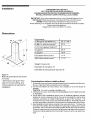
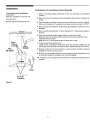
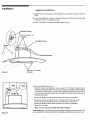
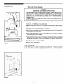
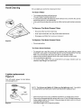
8] Electrolux
OWNER'S
GUIDE - Range Hood
PLHV36W7CC
READ AND SAVE THESE INSTRUCTIONS
CC_CC__L:_
PLHV38W7CC
- P/N 316137228
(Pub. No. 5995392130)
Product Registration
Register your Product
The self-addressed
PRODUCT
REGISTRATION CARD should be
filled in completely, signed and returned
to the ELECTROLUX Canada.
Thank you for choosing this appliance. The information contained within this
Owner's Guide will instruct you on hew to properly operate and care for your range
hood Please read through the information contained in your literature pack to learn
more about your new appliance.
Record Your Model and Serial
Numbers
Record in the space provided belowthe model and sedal hum bets found on the sedal
plate located on the dght hand side of the range hood
Model Number:
Serial Number:
Date of Purchase:
This Owner's Guide contains general
operating instructionsfor your range
hood and feature information for several
models. Your range may not have all
the descdbed features
Note: The instructions appearing inthis
Owner's Guide are net meant to cover
every possible condition and situation
that may occur. Common sense and
caution must be practiced when
installing, operating and maintaining any
appliance
2
READ AND SAVE THESE INSTRUCTIONS
Take care when using cleaning agents or detergents.
Suitable for use in household cooking area
CAUTION
- To reduce risk of fire and to propedy exhaust air, be sure to duct air outside - Do not vent exhaust air into
spaces within walls or ceilings or into attics, crawl spaces, or garages
CAUTION
- For General Ventilating Use Only Do Not Use To Exhaust Hazardous Or Explosive Materials And Vapors.
WARNING
- TO REDUCE THE RISK OF FIRE, ELECTRIC SHOCK, OR INJURY TO PERSONS, OBSERVE THE
FOLLOWING:
a Use this unit only in the manner intended by the manufacturer. If you have questions, contact the manufacturer.
b Before servicing or cleaning unit, switch power eft at service panel and lock t he service disconnecting meanste prevent
power from being switched on accidentally. When the service disconnecting means cannot be locked, securely fasten
a prominent warning device, such as a tag, to the service panel
WARNING
-TO
REDUCE THE RiSK OF A RANGE TOP GREASE FIRE:
a
Never leave sudace units unattended at high settings Boilovers cause smoking and greasy spilloversthat
Heat oils slowly on low or medium settings.
b Always turn hood ON when cooking at high heat or when ceoking flaming feeds.
c Clean ventilating fans frequently Grease should not be allowed to accumulate on fan or filter
d Use proper pan size. Always use cookware appropriate for the size of the surface element.
WARNING
OBSERVE
-TO REDUCE THE RISK OF INJURY TO PERSONS
THE FOLLOWING
INTHE EVENT OF A RANGE
may ignite
TOP GREASE
FIRE,
a
SMOTHER FLAMES with a close-fitting lid cookie sheet or metal tray then turn off the burner BE CAREFUL TO
PREVENT BURNS. If the flames do net go out immediately, EVACUATE AND CALL THE FIRE DEPARTMENT.
b NEVER PICK UP A FLAMING PAN - You may be burned.
c DO NOT USE WATER, including wet dishcloths or towels- a violent steam explosion will result.
d Use an extinguisher ONLY if:
1. You know you have a Class ABC extinguisher, and you already know howto operate it.
2. The fire is small and contained in the area where it started
3. The fire department is being called.
4. You can fight the fire with your back to an exit.
WARNING
- TO REDUCE THE RISK OF FIRE, ELECTRIC SHOCK, OR INJURY TO PERSONS, OBSERVE THE
FOLLOWING:
a) installation work and electrical wiring must be done by qualified person(s) in accordance with all applicable codes and
standards, including fire-rated construction.
b) Sufficient air is needed for proper combustion and exhausting of gases through the flue (chimney) of fuel burning
equipmentto prevent back drafting. Followthe heating equipment man ufacturer's guideline and safetystandardssuch
as those published by the National Fire Protection Association (NFPA), and the American Society for Heating,
Refrigeration and Air Conditioning Engineers (ASHRAE), and the local code authorities.
c) When cutting or drilling into wall or ceiling, de net damage electrical wiring and other hidden utilities
d) Ducted fans must always be vented to the outdoors.
WARNING
- TO REDUCE THE RISK OF FIRE, USE ONLY METAL DUCTWORK.
WARNING
'_"_WI_
Disconnect appliance from electric power before servicing.
Electrical Shock Hazard - Carl result in sedous injury or death
if equipped, the fluorescent light bulb contains small amounts of mercury which must be
recycled or disposed of according to Local, State, and Federal Codes
3
Installation
FOR RESIDENTIAL USE ONLY
NOT TO BE INSTALLED OVER GAS GRILLS
PLEASE READ ENTIRE INSTRUCTIONS BEFORE PROCEEDING,
INSTALLATION M UST COMPLY WITH ALL LOCAL CODES,
IMPORTANT: Save these Instructions for the Local Electdcal Inspector's use.
INSTALLER: Please leave these instructions with this unit for the owner.
OWNER: Please retain these instructions for future reference.
Safety Warning: Turn off power circuit at the service entrance and lock out panel,
before wiring this appliance.
Requirement: 120 V AC, 60 Hz 15 or 20 A
Dimensions
Dimensions
DD
A (Range of adjustable
A
t
ht.) *
29 W13-481F
B (Min. ht. with one cover)*
22 3/4
C (ht. from glass to bottom)*
3
W (widht)*
35 7/8
D (depth)*
195/8
DD (depth of the cover)*
11 5/8
WW (widht of the cover)*
11 31!6
Weight: 44 pounds
Diameter
of Transition
6"
Diameter of exhaust Duct required
6"
Figure 1"
Note: All dimensions
in inches.
are shown
* Dimensions are given from
base of hood to ceiling, and
include clearance required for
installation.
Considerations
before
installing
Hood
1 Grease filters are not mounted and are located inside the package with the hood
Be sure to get them before disposing of your package.
2 For the most efficient air flow exhaust, use a straight run or as few elbows as
possible
CAUTION: Vent unit to outside of building, only.
3 If allowed in yourarea, use metallicfiexducting onlyto connect rigid duct directly
to transitions.
4 COLD WEATHER installations should have an additional backdraft damper
installed to minimize backward cold air flow and a nonmetallic thermal break to
minimize conduction of outside temperatures as part of the ductwork The
damper should be on the cold air side of the thermal break The break should be
as close as possible to where the ducting enters the heated portion of the house
5 Hood installation height above cooktop isthe users preference. The lower the
hood above the cooktop, the more efficient the capturing of cooking odors, grease
and smoke We recommend the hood be installed 30-36" above the countertop
The lower height may be inconvenient for tall people and large cooking vessels
Check you r ceiling height and the hood height maxim um before you select your
hood.
4
Installation
Preparation
of mounting
surface (Drywall)
Tools required for installation
Screwdriver
(flat head, poziddve n°2 and torx 10)
1. Select a mounting height comfortable for the user and mark on wall behind
cooktop
Allen key 4ram
2. Mark center line of cooktop and draw vertical line from bottom of hood to the
ceiling
Electric ddll with twist bit _ 10 mm
3. Tape template, matching center-line and hood bottom as shown in Fig. 2
Distance from bottom of template to the ceiling must be minimum 2915/16"
4. Mark centers of the 6 fastener Iocatiensthreugh template on wall then remove
template.
5. Mark wall with hodzontal line 1" above highest and 1" below lowest fastener
CEILING/
,,,,,,,,,Y///////////////
location
Io
i
o II
6.
Find studs behind drywall by tapping wall or using a stud finder
Mark the center of the studs with a vertical line to the right and left of the
marked fastener location
Note: Each 2 x 6 must span at least 2 studs side to side
Upper
Fastener
mln,
29 15116!!
7. Cutout drywall along marked lines.
install each 2 x 6 between studs firmly flush with stud front. Make sure all
mounting screws will anchor to added lumber Replace drywall and refinish.
t;elling
Bracket
8. Remark center line and hood bottom on same location as before and tape
template on wall as in step 3 above
9. Mount 2 mounting hooks withwood screws (supplied in mounting hardware kit)
on locations marked on template, then remove template
10. Install duct cover ceiling bracket to wall flush to ceiling with drywall anchors
supplied
Hooks
L o w e
Fastener
Locations
r
Figure 2
5
Installation
Appliance
Installation:
1. Hang hood on 2 mounting hooksthroughthe
hood.
rectangularcutouts
on back of
2. Level the appliance, using a carpenters level across bottom of hood with
leveling screws in rectangular cutouts
3. Secure hood with 2 screws on bottom and 2 on top.
Leveling Screw
Rectangular
Cutouts
Leveling Screw
Hooks
top Fixing Screws
Figure 3
Bottom
Screws
Fixing
4. Connect ducting (Figure 4):
Note: for blower serviceability, leave a gap of 1" minimum between top of
transition and sheet metal duct and cover gap with a starting collar wrapped
areu nd duct and transition. Locate collar screws so they fit into comer of duct
cover Secu re cellarte transition and duct with three sheet metal screws each
Seal with duct tape.
Be sure to locate screws below damper lines drawn on transition
Mark onto exterior of transition the ,V' location of the damper within.
Secure ducting to transition with three sheet metal screws each.
Be sure to locate screws below damper lines drawn on transition
Seal with duct tape.
Note: Do not use duct smaller than the transition.
Figure 4
Rear discharge: A 90 ° elbow may be installed immediately above the hood. For
serviceability,a mounting similar to the straight up discharge should be used
6
Installation
Wiring to Power Supply
WARNING!
ELECTRICALGROUNDING INSTRUCTIONS
THISAPPLIANCE IS FITTED WITHAN ELECTRICAL JUNCTION BOXWITH
3 WIRES, ONE OF WHICH (GREEN/YELLOW) SERVESTO GROUNDTHE
APPLIANCE.
TO PROTECT YOU AGAINST ELECTRIC SHOCK, THE
GREEN AND YELLOWWIRE MUST BE CONNECTEDTO THE GROUNDING
WIRE IN YOUR
HOME ELECTRICALSYSTEM,AND
BE CUT OR REMOVED.
IT MUST UNDER NO CIRCUMSTANCES
Warn ing: Turn off power circu it at the service panel before wiring this u nit.
1. 120 VAC, 15 AMP branch circuit required.
2. Remove the junction box cover, unscrew the 4 screws that fix it to the body of
the hood.
3. install the conduit connector (1/2") in junction box.
4. Run 3 wires; black, white and green (wire gauge per code) in 1/2" conduit from
service panel to junction box.
5. Connect black wire from service panel to black or red in junction box, white to
white and green to green-yellow
6. Close junction box cover, with its 4 screws. Check all light bulbs to make sure
they are secure in their sockets Tum power on in service panel. Check lig hts
and blower operation per Care & Use section of this manual. Install filters
7. install duct cover as shown in Fig. 6
8. Fit the filters, see Page 9.
Figur_ 5
Rear discharge:
A 90 ° elbow may be installed immediately above the hood. For serviceability, a
mounting similar to the straight up discharge shown in Figure 4 should be used.
Figur_ 6
7
READ THE INSTRUCTIONS CAREFULLY BEFORE USING THE HOOD
For satisfactory use of your hood, become familiarwith the various functions of the
hood as described below
Use and Care
Suction power
3 LED, this led
is ON when
Suction power
2 LED, this led
is ON when
suction power
3 is selected.
suction power
2 is selected.
\
\
Motor OFF button
\
\
\
\
Light OFF button
\
\
\
\
\
\
\
\
\
iiiiii
f
Light ON button
\\
\
\
\
f
ON button and
motorsuction
/
\\
\
\
\
\
\\
power selection
button 1, 2, 3, 1,....
\
\\
Suction power
1 LED, this led
is ON when
suction power
1 is selected.
Intensive
Intensive
Suction power
LED, this led is
ON when the
intensive
Suction power
button - this
suction power
is selected.
again
the
preselected
speed
Figure 7
Grease
suction power
will function for
10 rains, then
the hood set
Filter
Saturation
LED
The Suction power 2 LED is marked with an F. This LED will flash to remind you when the grease filter needs to be cleaned
after 40 hours use. Follow the instructions for cleaning filters in this booklet. Once the grease filters have been cleaned, reset
the reminder by pressing Motor OFF button for about 3 seconds until you hear the signal (beep).
Should the Suction power 3 LED starts to flash then push ON and power selection button and the Intensive Suction power
button simultaneously for more than 3 seconds to stop flashes.
Operating
Instructions
The blower should be turned on for about 5 minutes before cooking in order to establish air currents upward through the hood.
Use the low speeds for normal use and the big her speeds for strong odors or fumes
Minimize cross drafts which will reduce the effectiveness of the hood.
8
Hood Clean in g
Be sure lights are cool before cleaning the hood
To Clean Filters
• The metal grease filters will last forever
They are made of anodized aluminum
• It is recommended that the filters be washed at least once a month; they can be
washed by hand or in the dishwasher.
• Drain waterthrough edge holes and let each filterdrythoroughly before replacing
it
To Remove
The Metal Grease
• Disconnectthe
Filters
hood from electricity
• Push clips towards the rear and pull the filters downward
I
• Disengage each filterfrom a side and remove it
To Replace
Figure 8
The Metal
Grease
Filters
• Reverse procedure
To Clean Hood Surface
• For general care, wipe the outside of the stainless steel, white, black or glass
hood with sudsy water or household cleaners such as Fantastic_ or Formula
409 _, rinse well and dry with clean soft cloth to avoid water marks
• Wipe and dry brushed stainless steel in the same direction as the grain
• Do not use abrasive products.
• To remove finger pdnts and give added shine use spray cleaners such as
Stainless Steel Magic ®and Shimmer _
Lights replacement
Figure 9
Turn off electric power to hood before
removing light cover
NOTE: Turn blower and lights off. Make sure the lights are cool. if new lights
do not operate be sure lights are inserted correctly before calling service.
®
=_" _
Light
Lightcover
Figure 9
• Remove the light cover using a little flat screwdriver or similar tcol as a lever
• Remove the damaged light and replace with a new 12 Volt, 20 Watt (maxim urn)
halogen light made for a G-4 base Follow package directions and do not touch
new light with bare hands
• Reinstall the light cover (snap into position)
9
RANGE HOOD WARRANTY
Your range hood is protected
WARRANTY
PERIOD
FULLONE-YEAR
WARRANTY
by this warranty
THROUGHOUR AUTHORIZED SERVICERS,
WE WILL:
Oneyearfrom odginal Payall costs forrepairing or replacinganyparts ofthis
purchasedate.
appliancewhich proveto be defectivein materials or
workmanship.
LIMITED WARRANTY Timeperiodslisted
(Applicableto the
above,
State of Alaska)
All ofthe provisionsof the fulland limitedwarranties
above andthe exclusionslistedbelow apply,
THE CONSUMER WILL BE RESPONSIBLE FOR:
Coats of servicecallsthat are listedunderNORMAL
RESPONSIBILITIESOF THE CONSUMER.*
Coatsof thetechnician'stravelto the homeandany
costsforpick upand deliveryof the appliancerequired
becauseof service.
In the U,S.A., your appliance is warranted by Eioctroiux Home Products North America, a division of White Consolidated Industries, Inc. We
authorize no person to change or add to any of our obtigations under this warranty, Our obligations for sowioe and parts under this warranty must
be performed by us or an authorized Eloctralux Home Products North America servicer. In Canada, your apptiance is warranted by WCI Canada
Inc.
*NORMAL
RESPONSIBILITIES
OF THE CONSUMER
This warranty applies
items listed below:
1,
2,
3.
4,
5,
6,
EXCLUSIONS
2,
3,
4.
IFYOU NEED
SERVICE
in ordinary household
use, and the consumer
is responsible
for the
Proper use of the appliance in accordance with instructions provided with the product.
Proper installation by an authorized servicer in accordance with instructions provided with the appliance and in
accordance with all tocal plumbing, electrical and/or gas codes.
Proper connection to a grounded power supply of sufficient voltage, replacement of btown fuses, repair of tooso
connections or defects in house wiring,
Expenses for making the appliance accessible for servicing, such as removat of trim, cupboards, shelves,etc.
which are not a part of the appliance when it was shipped from the factory,
Damages to finish after installation.
Replacement of light bulbs and/or fluorescent tubes (on models with these features).
This warranty
1.
only to products
does not cover the following:
CONSEQUENTIAL OR INCIDENTAL DAMAGES SUCH AS PROPERTY DAMAGE AND INCIDENTAL
RESULTING FROM ANY BREACH OF THIS WRITTEN OR ANY IMPLIED WARRANTY.
EXPENSES
NOTE: Some states do not allow the exclusion or limitation of incidental or consequential damages, so this
limitation or exclusion may not appty to you.
Service calls which do not involve malfunction or defects in workmanship or material, or for appliances not in
ordinary household use. The consumer shall pay for such service calls,
Damages caused by services performed by servicers other than Electrolux Home Products North America or its
authorized servicers; use of parts other than genuine Electroiux Home Products parts; obtained from persons
other than such servicers; or external causes such as abuse, misuse, inadequate power supply or acts of God.
Products with original serial numbers that have been removed or altered and cannot be readily determined.
Keep your bilt of sate, delivery slip, or some other appropriate payment record. The date on the bilJ establishes the
warranty period should service be required, If service is performed, }t is in your best interest to obtain and keep all
receipts. This written warranty gives you specific legal rights, You may also have other rights that vary from state to state.
Service under this warranty must be obtained by contacting Eloctralux Home Products:
This warranty only applies in the 50 states of the U.S.A., Puerto Rico, and Canada. Product features or specifications as described or illustrated are
subject to change without notice. All warranties are made by Electrolux Home Products North America, a division of White Consolidated Industries
inc. In Canada, your appliance is warranted by WCI Canada, Inc.
USA
800.944,,9044
Efectralux Home Products North America
P.O. Box 212378
Augusta,
GA 30917
03-U-RH-02
Canada
866.213.9397
(English)
866.294.9911
(French)
Etectrotux Home Products North America
6150 McLaughlin Road
Mississauga, Ontario, Canada
L5R 4C2