1
Trademarks
MELDAS, MELSEC, EZSocket, EZMotion, iQ Platform, MELSOFT, GOT, CC-Link, CC-Link/LT and CC-Link
IE are either trademarks or registered trademarks of Mitsubishi Electric Corporation in Japan and/or other
countries.
Ethernet is a registered trademark of Xerox Corporation in the United States and/or other countries.
Microsoft® and Windows® are either trademarks or registered trademarks of Microsoft Corporation in the
United States and/or other countries.
CompactFlash and CF are either trademarks or registered trademarks of SanDisk Corporation in the United
States and/or other countries.
Other company and product names that appear in this manual are trademarks or registered trademarks of
the respective companies.
Contents
I Alarms
1. Operation Errors (M) ............................................................................................ 1
2. Stop Codes (T) ..................................................................................................... 6
3. Servo/Spindle Alarms (S) ................................................................................... 10
3.1 Servo Errors (S01/S03/S04) .................................................................... 10
3.2 Initial Parameter Errors (S02) .................................................................. 21
3.3 Safety Function Errors (S05) ................................................................... 21
3.4 Parameter Errors (S51)............................................................................ 22
3.5 Servo Warnings (S52).............................................................................. 23
3.6 Safety Function Warnings (S53) .............................................................. 25
4. MCP Alarms (Y) ................................................................................................. 26
5. Safety Observation Alarms (Y)........................................................................... 32
5.1 Safety Observation Alarms ...................................................................... 32
5.2 Safety Observation Warnings .................................................................. 37
6. System Alarms (Z).............................................................................................. 38
7. Absolute Position Detection System Alarms (Z7*) ............................................. 41
8. Emergency Stop Alarms (EMG) ......................................................................... 44
9. Auxiliary Axis Operation Errors (M) .................................................................... 46
10. CNCCPU-side Safety Sequence Alarm(U) ...................................................... 47
11. Multi CPU Errors (A)......................................................................................... 48
12. Network Errors (L) ............................................................................................ 65
13. Program Errors (P) ........................................................................................... 71
II Parameters
1. Machining Parameters ......................................................................................... 1
2. Base Specifications Parameters .......................................................................... 6
3. Axis Specifications Parameters.......................................................................... 45
4. Servo Parameters .............................................................................................. 58
5. Spindle Parameters............................................................................................ 84
6. Multi-CPU Parameters ..................................................................................... 124
7. FL-net Parameters ........................................................................................... 125
8. DeviceNet Parameters ..................................................................................... 134
9. Machine Error Compensation Parameters ....................................................... 144
10. PLC Parameters ............................................................................................. 145
11. Macro List ....................................................................................................... 146
12. Position Switches ........................................................................................... 154
13. PLC Axis Indexing Parameters ...................................................................... 163
III PLC Devices
1. Bit Type Input Signals (CNC->PLC) ..................................................................... 1
1.1 System State.............................................................................................. 1
1.2 Axis State................................................................................................... 7
1.3 Part System State .................................................................................... 11
1.4 Spindle State............................................................................................ 19
2. Data Type Input Signals (CNC->PLC)................................................................ 22
2.1 System State............................................................................................ 22
2.2 Part System State .................................................................................... 25
2.3 Axis State................................................................................................. 30
2.4 Spindle State............................................................................................ 31
3. Bit Type Output Signals (PLC->CNC) ................................................................ 33
3.1 System Command ................................................................................... 33
3.2 Axis Command......................................................................................... 39
3.3 Part System Command............................................................................ 45
3.4 Spindle Command ................................................................................... 59
4. Data Type Output Signals (PLC->CNC)............................................................. 62
4.1 System Command ................................................................................... 62
4.2 Part System Command............................................................................ 65
4.3 Axis Command......................................................................................... 70
4.4 Spindle Command ................................................................................... 72
5. Each Application................................................................................................. 74
5.1 PLC Axis State......................................................................................... 74
5.2 PLC Axis Control...................................................................................... 77
5.3 Window Result Information ...................................................................... 80
5.4 Window Command................................................................................... 85
5.5 Data Registered to Magazine for M System ............................................ 95
5.6 Tool Life Management (M System).......................................................... 97
5.7 Safety Observing ..................................................................................... 99
5.8 PLC Constants....................................................................................... 102
5.9 PLC Bit Selection ................................................................................... 105
5.10 PLC Axis Indexing Interface................................................................. 107
6. Special Relay/Register Signals ........................................................................ 109
6.1 Special Relay ......................................................................................... 109
6.2 Special Register..................................................................................... 113
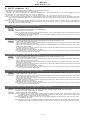
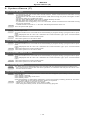
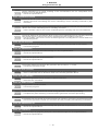
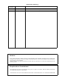
Remedy and measure after a report of error
IMPORTANT
1. Take a detailed note of the operations applied just before the error occurrence.
2. Operation history is regularly updated. Therefore, interruption should be carried out just after the error
occurrence.
<Preparation>
- Confirm that the operation history of alarm diagnosis is set to "P: Execute" so that the error data can
be collected. Error data can be kept in this state. The back ground of "P: Execute" is reversed in white.
- After having collected error data, return the operation history to "P: Execute".
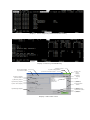
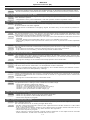
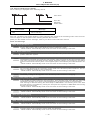
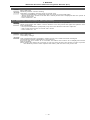
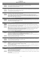
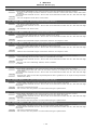
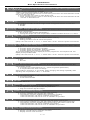
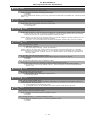
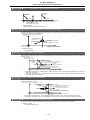
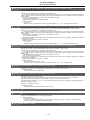
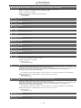
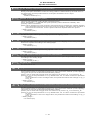
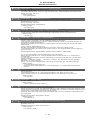
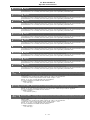
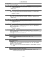
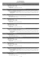
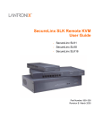
<Sequence of remedy and measure>
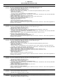
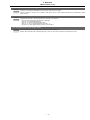
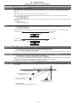
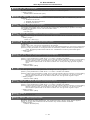
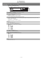
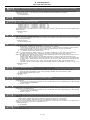
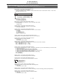
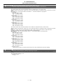
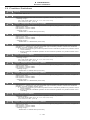
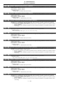
(1)
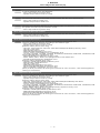
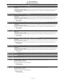
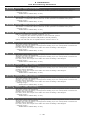
Select [HISTORY] in the alarm diagnosis.
Set [I] in #( ) and press enter. The operation history will be interrupted.
Display 1 shows the stop state.
The back ground of the operation history
is turned white.
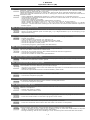
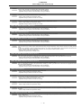
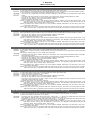
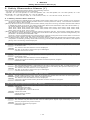
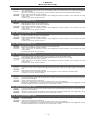
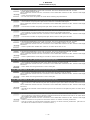
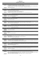
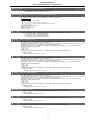
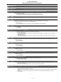
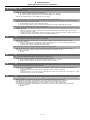
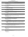
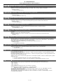
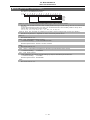
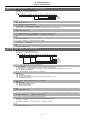
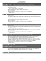
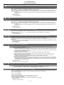
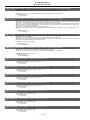
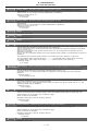
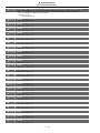
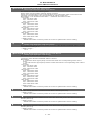
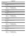
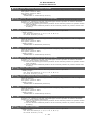
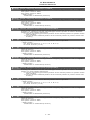
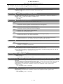
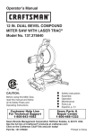
(2)
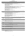
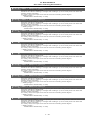
Select [COORDI] on monitor. Note down
value of coordinates, programming number under the operation, etc.
Note down the information on display 2.
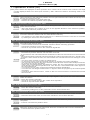
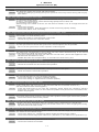
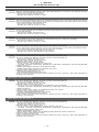
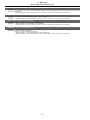
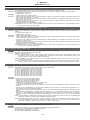
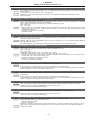
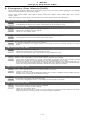
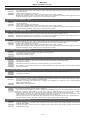
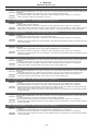
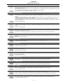
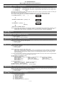
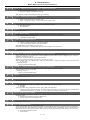
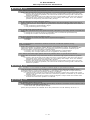
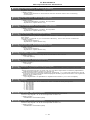
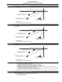
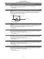
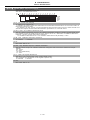
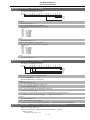
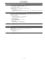
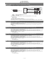
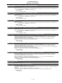
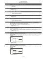
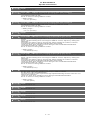
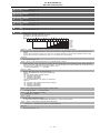
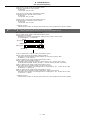
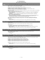
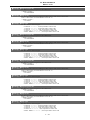
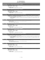
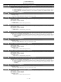
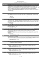
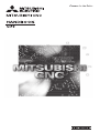
(3)
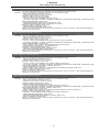
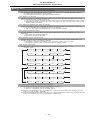
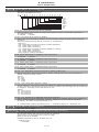
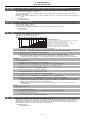
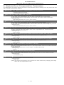
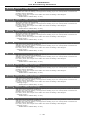
Collect SRAM.BIN data in CNC data input function.
Refer to display 3
(a) Function: Select "COPY"
(b) Device: Select "CNC"
(c) Directory: Select "Mainte data”
(d) File name: Select "SRAM.BIN"
(e) Scroll down to under the arrow.
(f) Device: Select the output destination
for the above data.
(g) Press [Exec] on the bottom right.
(4)
Select ""Backup function (Device->GOT)" to collect PC CPU data and CNC CPU data with the
restored backup function.
(5)
Provide us with the SRAM.BIN and the restored backup data.
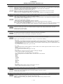
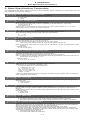
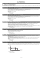
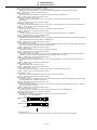
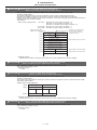
Display 1 :Alarm diagnosis [OPERATION HISTORY]
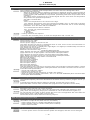
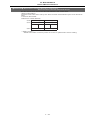
Display 2: Monitor [COORDINATE]
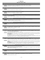
3) Return button
6) Function display
5) Function button
2) CNC change button
1) Channel selection button
4) CNC unit
name
display
12) Status
display
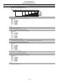
8) Device display
7) Device button
13) List
9) Directory button
14) Scroll up
button
10) Directory display
11) File name display
15) Scroll down
button
16) Area change
button
17) Refresh button
19) Message display
18) Execute
button
Display 3:CNC Data In/Out
I Alarms
I Alarms
Operation Errors (M)
1. Operation Errors (M)
(Note) "M01" alarms are displayed as "M01 Operation error" with the error number. Error number is four digit
number displayed after error name (such as 0001). "M01" alarms are listed in ascending order in this
manual.
M01 Dog overrun 0001
Details
When returning to the reference position, the near-point detection limit switch did not stop over
the dog, but overran the dog.
Remedy - Increase the length of the near-point dog.
- Reduce the reference position return speed.
M01 Some ax does not pass Z phase 0002
Details
One of the axes did not pass the Z-phase during the initial reference position return after the
power was turned ON.
Remedy - Move the detector one rotation or more in the opposite direction of the reference position,
and repeat reference position return.
M01 R-pnt direction illegal 0003
Details
When manually returning to the reference position, the return direction differs from the axis
movement direction selected with the AXIS SELECTION key.
Remedy - The selection of the AXIS SELECTION key's +/- direction is incorrect. The error is canceled
by feeding the axis in the correct direction.
M01 External interlock axis exists 0004
Details
The external interlock function has activated (the input signal is "OFF") and one of the axes
has entered the interlock state.
Remedy - As the interlock function has activated, release it before resuming operation.
- Correct the sequence on the machine side.
- Check for any broken wires in the "interlock" signal line.
M01 Internal interlock axis exists 0005
Details
The internal interlock state has been entered.
- The absolute position detector axis has been removed.
- A command for the manual/automatic simultaneous valid axis was issued from the automatic
mode.
- The manual speed command was issued while the "tool length measurement 1" signal is ON.
- In NC/PLC axes switch function, the manual feed was commanded from NC during PLC axis
control.
Remedy - The servo OFF function is valid, so release it first.
- An axis that can be removed has been issued, so perform the correct operations.
- The command is issued in the same direction as the direction where manual skip turned ON,
so perform the correct operations.
- During the manual/automatic simultaneous mode, the axis commanded in the automatic
mode became the manual operation axis. Turn OFF the "manual/automatic valid" signal for
the commanded axis.
- Turn ON the power again, and perform absolute position initialization.
- Turn OFF the "tool length measurement 1" signal to start the program by the manual speed
command.
- In NC/PLC axes switch function, switch to NC axis control and then command the manual
feed from NC.
M01 H/W stroke end axis exists 0006
Details
The stroke end function has activated (the input signal is "OFF") and one of the axes is in the
stroke end status.
Remedy - Move the machine manually.
- Check for any broken wires in the "stroke end" signal line.
- Check for any limit switch failure.
M01 S/W stroke end axis exists 0007
Details
The stored stroke limit I, II, IIB or IB function has activated.
Remedy - Move the machine manually.
- Correct any setting error of the parameters for the stored stroke limit.
M01 Chuck/tailstock stroke end ax 0008
Details
The chuck/tail-stock barrier function turned ON, and an axis entered the stroke end state.
Remedy - Reset the alarm with reset, and move the machine in the reverse direction.
M01 Ref point return No. invalid 0009
Details
2nd reference position return was performed before 1st reference position return has been
completed.
Remedy - Execute 1st reference position return.
M01 Ref point retract invalid 0020
Details
Reference position retract was performed while the coordinates had not been established.
Remedy - Execute reference position return.
I-1
I Alarms
Operation Errors (M)
M01 R-pnt ret invld at abs pos alm 0024
Details
A reference position return signal was enabled during an absolute position detection alarm.
Remedy - Reset the absolute position detection alarm, and then perform the reference position return.
M01 R-pnt ret invld at zero pt ini 0025
Details
A reference position return signal was input during zero point initialization of the absolute position detection system.
Remedy - Complete the zero point initialization, and then perform reference position return.
M01 Chopping axis R-pnt incomplete 0050
Details
Chopping mode has been entered while the chopping axis has not completed reference position return.
All axes interlock has been applied.
Remedy - Reset the NC or disable the "chopping" signal, and then carry out the reference position re-
turn.
M01 Synchronous error excessive 0051
Details
The synchronization error of the primary and secondary axes exceeded the allowable value
under synchronous control. A deviation exceeding the synchronization error limit value was
found with the synchronization deviation detection.
Remedy - Select the correction mode and move one of the axes in the direction in which the errors are
reduced.
- Increase "#2024 synerr(allowable value)" or set "0" to disable error check.
- When using simple C-axis synchronous control, set "0" for "synchronous control operation
method".
M01 Wait for tap retract 0057
Details
The axis travel command is interlocked in the part system where the "Tap retract possible" signal is ON.
Remedy - If tap retract is necessary, perform it before issuing an axis travel command.
- If tap retract is not necessary, cancel the tap retract enabled state.
M01 Handle ratio too large 0060
Details
- The handle ratio is too large for the handle feed clamp speed.
(The handle feed clamp speed changes according to the rapid traverse rate, external feedrate, maximum speed outside the soft limit range and etc. (or external deceleration speed
when external deceleration is valid))
Remedy - Change the settings of the handle feed clamp speed or the handle ratio.
M01 Hypothetical axis high-accuracy control: Non-interpolation error 0090
Details
Remedy
High-accuracy control was commanded in hypothetical axis command mode in the hypothetical linear axis control. Otherwise, non-interpolation mode is selected.
- Correct "#1086 G0Intp (G00 non-interpolation)" and "#1205 G0bdcc (Acceleration and deceleration before G0 interpolation)" settings.
M01 Hypothetical linear axis control: Commanded axis illegal 0091
Details
Remedy
Under hypothetical linear axis control, a command was issued to an actual axis on hypothetical plane in hypothetical axis command mode or issued to a hypothetical axis in actual axis
command mode.
- Change the commanded axis or command mode.
M01 Hypothetical axis movable range exceeded 0092
Details
Remedy
A hypothetical axis is being moved outside the movable range.
- Correct the following parameter setting:
"#12015 v_dist (Hypothetical axis tool length)",
"#12016 v_ori (Hypothetical axis machine zero point)",
"#12020 r_lim+ (Actual axis movable range (+))",
"#12021 r_lim- (Actual axis movable range (-))"
M01 No operation mode 0101
Details
No operation mode
Remedy - Check for any broken wires in the input mode signal line.
- Check for any failure of the MODE SELECT switch.
- Correct the sequence program.
M01 Cutting override zero 0102
Details
The "cutting feed override" switch on the machine operation panel or the "rapid traverse override" switch is set to"0".
The override was set to "0" during a single block stop.
Remedy - Set the "cutting feed override" switch or the "rapid traverse override" switch to a value other
than "0" to clear the error.
- If the "cutting feed override" switch or the "rapid traverse override" switch has been set to a
value other than "0", check for any short circuit in the signal line.
- Correct the sequence program.
- When using the cutting feedrate override method selection or the rapid traverse override
method selection, check if the override ratio is not zero.
I-2
I Alarms
Operation Errors (M)
M01 External feed rate zero 0103
Details
MANUAL FEEDRATE switch on the machine operation panel is set to "0" when the machine
is in the JOG or automatic dry run mode.
"Manual feedrate B" is set to "0" during the JOG mode when manual feedrate B is valid.
"Each axis manual feedrate B" is set to "0" during the JOG mode when each axis manual feedrate B is valid.
Remedy - Set the MANUAL FEEDRATE switch to a value other than "0" to release the error.
- If the MANUAL FEEDRATE switch has been set to a value other than "0" check for any short
circuit in the signal line.
- Correct the sequence program.
- Correct the external deceleration parameters as follows:
When "#1239 set11/bit6" is set to "0", set a non-zero value in "#1216 extdcc".
When "#1239 set11/bit6" is set to "1", set a non-zero value in "#2086 exdcax1" or "#2161
exdcax2" - "#2165 exdcax6" referring to the value set in the external deceleration speed selection signal.
M01 F 1-digit feed rate zero 0104
Details
The F1-digit feedrate has been set to "0" when the F1-digit feed command was executed.
Remedy - Set the F1-digit feedrate (from "#1185 spd_F1 (F1 digit feedrate F1)" to "#1189 spd_F5 (F1
digit feedrate F5)").
M01 Spindle stop 0105
Details
The spindle stopped during the synchronous feed/thread cutting command.
Remedy - Rotate the spindle.
- If the workpiece is not being cut, start dry run.
- Check for any broken wire in the spindle encoder cable.
- Check the connections for the spindle encoder connectors.
- Check the spindle encoder pulse.
- Correct the program. (commands and addresses)
M01 Handle feed ax No. illegal 0106
Details
The axis, designated at handle feed, is out of specifications.
No axis has been selected for handle feed.
Remedy - Check for any broken wires in the handle feed axis selection signal line.
- Correct the sequence program.
- Check the number of axes in the specifications.
M01 Spindle rotation speed over 0107
Details
Spindle rotation speed exceeded the axis clamp speed during the thread cutting command.
Remedy - Lower the commanded rotation speed.
M01 Fixed pnt mode feed ax illegal 0108
Details
The axis, designated in the manual arbitrary feed, is out of specifications.
The feedrate in manual arbitrary feed mode is illegal.
Remedy - Check for any broken wires in the axis selection signal line or the feedrate line for the manual
arbitrary feed mode.
- Check the specifications for the manual arbitrary feed mode.
M01 Block start interlock 0109
Details
An interlock signal has been input to lock the block start.
Remedy - Correct the sequence program.
M01 Cutting block start interlock 0110
Details
An interlock signal has been input to lock the cutting block start.
Remedy - Correct the sequence program.
M01 Restart switch ON 0111
Details
Restart switch has been turned ON and manual mode has been selected before the restart
search is completed.
Remedy - Search the block to restart.
- Turn the restart switch OFF.
M01 Program check mode 0112
Details
The automatic start button was pressed during program check or in program check mode.
Remedy - Press the reset button to cancel the program check mode.
M01 Auto start in buffer correct 0113
Details
The automatic start button was pressed during buffer correction.
Remedy - Press the automatic start button after the buffer correction is completed.
M01 In reset process 0115
Details
The automatic start button was pressed during resetting or tape rewinding.
Remedy - When rewinding the tape, wait for the winding to end, or press the reset button to stop the
winding, and then press the automatic start button.
- During resetting, wait for the resetting to end, and then press the automatic start button.
I-3
I Alarms
Operation Errors (M)
M01 Playback not possible 0117
Details
The playback switch was turned ON during editing.
Remedy - Cancel the editing by pressing the input or previous screen key before turning ON the play-
back switch.
M01 Turn stop in normal line cntrl 0118
Details
The turning angle at the block joint exceeded the limit during normal line control.
In normal line control type I:
"#1523 C_feed (Normal line control axis turning speed)" has not been set.
In normal line control type II:
When turning in the inside of the arc, the set value for "#8041 C-rot. R" is larger than the arc
radius.
Remedy - Correct the program.
- Correct the "#1523 C_feed (Normal line control axis turning speed)" setting.
- Correct the "#8041 C rot. R" setting.
M01 Illegal operation mode for synchronous correction mode 0120
Details
While synchronization correction mode is ON, operation mode is illegally set to a mode other
than handle or manual arbitrary feed.
Remedy - Select the handle or manual arbitrary feed mode.
- Cancel the synchronous correction mode.
M01 No synchronous control option 0121
Details
A value was entered to the synchronous control operation method register when multi-secondary-axis synchronous control and synchronous control options are not provided.
Remedy - Set "0" for the synchronous control operation method register.
M01 X/Z axes simultaneous prohibit 0124
Details
The basic axis corresponding to the inclined axis was started simultaneously in the manual
mode while the inclined axis control was valid.
Remedy - Turn the inclined axis and basic axis start OFF for both axes. (This is also applied for man-
ual/automatic simultaneous start.)
- Disable the basic axis compensation, or command it to axes one by one.
M01 Program restart machine lock 0126
Details
Machine lock was applied on the return axis being manually returned to the restart position.
Remedy - Cancel the machine lock and resume the operation.
M01 Zero point return interruption 0131
Details
Automatic operation was started after a zero point return interruption.
Remedy - Reset and start the automatic operation.
M01 Chopping override zero 0150
Details
The override became "0" in the chopping operation.
Remedy - Correct the setting of "chopping override" (R2503).
- Correct the setting of "rapid traverse override" (R2502).
M01 Command axis chopping axis 0151
Details
A chopping axis movement command was issued from the program during the chopping
mode. (This alarm will not occur for the command with the movement amount "0".)
(All axes interlock state will be applied.)
Remedy - Press the reset button or turn OFF the "chopping" signal. When the "chopping" signal is
turned OFF, the axis returns to the reference position and performs the movement command in the program.
M01 Bottom dead center pos. zero 0153
Details
The bottom dead center position is set to the same position as the upper dead center position.
Remedy - Correct the bottom dead center position.
M01 Chopping disable for handle ax 0154
Details
Chopping has been attempted while the chopping axis is selected as the handle axis.
Remedy - Select an axis other than the chopping axis as the handle axis, or start chopping after chang-
ing the mode to the other mode.
M01 No speed set out of soft limit 0160
Details
The axis, without any maximum speed outside of the soft limit range set, was returned from
the outside of the soft limit range.
Remedy - Correct the "#2021 out_f (Maximum speed outside soft limit range)" setting.
- Correct the soft limit range (with "#2013 OT- (Soft limit I-)" and "#2014 OT+ (Soft limit I+)").
M01 APLC password mismatch 0280
Details
The APLC authentication password is inconsistent.
Remedy - Contact the machine tool builder.
I-4
I Alarms
Operation Errors (M)
M01 G114.n command illegal 1005
Details
G114.n has been commanded during the execution of G114.n.
G51.2 has been commanded when G51.2 spindle-spindle polygon machining mode has been
already entered at another part system.
Remedy - Command G113 to cancel the operation.
- Turn ON the "spindle synchronization cancel" signal to cancel the operation.
- Command G50.2 to cancel the operation.
- Turn ON the "spindle-spindle polygon cancel" signal to cancel the operation.
M01 Synchro ctrl setting disable 1036
Details
"Synchronous control operation method" was set (with R2589) when the mode was not the C
axis mode.
"Synchronous control operation method" was set (with R2589) in the zero point not set state.
Mirror image is disabled.
External mirror image or parameter mirror image was commanded during facing turret mirror
image.
Remedy - Set the contents of the R2589 register to "0".
- Correct the program and parameters.
M01 External spindle speed clamp speed zero 1039
Details
External spindle speed clamp signal has been turned ON while the clamp speed has not been
set.
Remedy - Set the external spindle speed clamp feedrate parameter.
- Turn OFF the external spindle speed clamp signal.
M01 No spindle speed clamp 1043
Details
Remedy
The constant surface speed command (G96) was issued to the spindle which is not selected
for the spindle speed clamp command (G92/G50) under Multiple spindle control II.
Press the reset key and carry out the remedy below.
- Select the spindle before commanding G92/G50.
M01 Sp synchro phase calc illegal 1106
Details
Spindle synchronization phase alignment command was issued while the "phase shift calculation request" signal was ON.
Remedy - Correct the program.
- Correct the sequence program.
M01 NC/PLC axis switch illegal 1250
Details
Remedy
The following operation was performed to an axis which can be switched over between NC
axis and PLC axis.
- PLC axis switchover signal was turned ON or OFF when it was prohibited to switch over the
axis.
Make sure the axis switchover status signal is OFF and change the ON/OFF of the axis switchover signal.
M90 Parameter set mode
Details
Remedy
The lock for setup parameters has been released. Setting the setup parameters is enabled
while automatic start is disabled.
Refer to the manual issued by the machine tool builder.
I-5
I Alarms
Stop Codes (T)
2. Stop Codes (T)
T01 Cycle start prohibit
Automatic start is not available in stop state.
T02 Feed hold
Feed hold is actuated during automatic operation for some reason.
T03 Block stop
Block stop is actuated during automatic operation for some reason.
(Note 1) "T01" stop codes are displayed as "T01 Cycle start prohibit" with the error number. Error number is
four digit number displayed after error name (start from 0101). "T01" stop codes are listed in ascending
order in this manual.
(Note 2) "T02" stop codes are displayed as "T02 Feed hold" with the error number. Error number is four digit
number displayed after error name (start from 0201). "T02" stop codes are listed in ascending order in
this manual.
(Note 3) "T03" stop codes are displayed as "T03 Block stop" with the error number. Error number is four digit
number displayed after error name (start from 0301). "T03" stop codes are listed in ascending order in
this manual.
T01 Axis in motion 0101
Details
Automatic start is not possible as one of the axes is moving.
Remedy - Try automatic start again after all axes have stopped.
T01 NC not ready 0102
Details
Automatic start is not possible as the NC is not ready.
Remedy - Another alarm has occurred. Check the details and remedy.
T01 Reset signal ON 0103
Details
Automatic start is not possible as the "reset" signal has been input.
Remedy - Turn OFF the "reset" signal.
- Check for any failure of the reset switch which has caused the switch's continuous ON.
- Correct the sequence program.
T01 Auto operation pause signal ON 0104
Details
The feed hold switch on the machine operation panel is ON (valid).
Remedy - Correct the feed hold switch setting.
- The feed hold switch is B contact switch.
- Fix any broken wires in the feed hold signal line.
- Correct the sequence program.
T01 H/W stroke end axis exists 0105
Details
Automatic start is not possible as one of the axes is at the stroke end.
Remedy - Manually move any axis whose end is at the stroke end.
- Check for any broken wires in the stroke end signal line.
- Check for any failure in the stroke end limit switch.
T01 S/W stroke end axis exists 0106
Details
Automatic start is not possible as one of the axes is at the stored stroke limit.
Remedy - Move the axis manually.
- If the axis's end is not at the stroke end, check the parameters.
T01 No operation mode 0107
Details
The operation mode has not been selected.
Remedy - Select automatic operation mode.
- Check for any broken wires in the signal line for automatic operation mode (memory, FTP,
MDl).
T01 Operation mode duplicated 0108
Details
Two or more automatic operation modes have been selected.
Remedy - Check for any short circuit in the mode (memory, FTP, MDl) selection signal line.
- Check for any failure in the switch.
- Correct the sequence program.
T01 Operation mode changed 0109
Details
The automatic operation mode has changed to another automatic operation mode.
Remedy - Return to the original automatic operation mode, and execute automatic start.
T01 Tape search execution 0110
Details
Automatic start is not possible as tape search is being executed.
Remedy - Wait for the tape search to be completed and then execute the automatic start.
T01 Restart search in execution 0111
Details
Automatic start is disabled because restart search is in execution.
Remedy - Execute automatic start after the restart search is completed.
I-6
I Alarms
Stop Codes (T)
T01 Restart pos. return incomplete 0112
Details
Automatic start is not possible as the axis has not been returned to the restart position.
Remedy - Manually return the axis to the restart position.
- Turn ON the automatic restart valid parameter, and then execute the automatic start.
- Return to the restart position, and execute the automatic start in MDI mode.
T01 CNC overheat 0113
Details
Automatic start is not possible because a thermal alarm (Z53 CNC overheat) has occurred.
Remedy - Temperature of the control unit has exceeded the specified temperature.
- Take appropriate measures to cool the unit.
T01 Cycle st prohibit(Battery alm) 0116
Details
Automatic start is not possible because the voltage of the battery in the NC control unit has
dropped.
Automatic start is not possible because the voltage of the battery in the servo drive unit has
dropped.
Remedy - Replace the battery of the NC control unit.
- Replace the battery of the servo drive units.
- Contact the service center.
T01 In absolute position alarm 0138
Details
A start signal was input during an absolute position detection alarm.
Remedy - Clear the absolute position detection alarm, and then input the start signal.
T01 In abs posn initial setting 0139
Details
A start signal was input during zero point initialization in the absolute position detection system.
Remedy - Complete zero point initialization before inputting the start signal.
T01 Start during MDI operation at other part system disable 0141
Details
In multi-part system, a start signal was input for MDI mode while the MDI operation was being
carried out in another part system.
Remedy - End the other part system's operation before starting.
T01 APLC password mismatch 0160
Details
Automatic start is disabled because the APLC authentication password does not match.
Remedy - Contact the machine tool builder.
T01 Cycle start prohibit 0180
Details
Automatic start became disabled while servo auto turning is enabled.
Remedy - Set "#1164 ATS" to "0" when the servo auto turning is not executed.
T01 Cycle start prohibit 0190
Details
Automatic start is not possible because the setting of setup parameters is enabled.
Remedy - Refer to the manual issued by the machine tool builder.
T01 Cycle start prohibit 0191
Details
Automatic start was attempted while a file was being deleted/written.
Remedy - Wait for the file to be deleted/written and then execute the automatic start.
T02 H/W stroke end axis exists 0201
Details
An axis is at the stroke end.
Remedy - Manually move the axis away from the stroke end limit switch.
- Correct the machining program.
T02 S/W stroke end axis exists 0202
Details
An axis is at the stored stroke limit.
Remedy - Manually move the axis.
- Correct the machining program.
T02 Reset signal ON 0203
Details
The reset has been entered.
Remedy - The program execution position has returned to the start of the program. Execute automatic
operation from the start of the machining program.
T02 Auto operation pause signal ON 0204
Details
The "feed hold" switch is ON.
Remedy - Press the CYCLE START switch to resume the automatic operation.
I-7
I Alarms
Stop Codes (T)
T02 Operation mode changed 0205
Details
The operation mode has changed to another mode during automatic operation.
Remedy - Return to the original automatic operation mode, and press the CYCLE START switch to
resume the automatic operation.
T02 Acc/dec time cnst too large 0206
Details
The acceleration and deceleration time constants are too large. (This alarm occurs with the
system alarm Z59.)
Remedy - Set a larger value for "#1206 G1bF(Maximum speed)".
- Set a smaller value for "#1207 G1btL(Time constant)".
- Set a lower cutting speed.
T02 Abs posn detect alarm occurred 0215
Details
An absolute position detection alarm occurred.
Remedy - Clear the absolute position detection alarm.
T03 Single block stop signal ON 0301
Details
The SINGLE BLOCK switch on the machine operation panel is ON.
The SINGLE BLOCK or MACHINE LOCK switch changed.
Remedy - Press the CYCLE START switch to resume the automatic operation.
T03 Block stop cmnd in user macro 0302
Details
A block stop command was issued in the user macro program.
Remedy - Press the CYCLE START switch to resume the automatic operation.
T03 Operation mode changed 0303
Details
Automatic mode changed to another automatic mode.
Remedy - Return to the original automatic operation mode, and press the CYCLE START switch to
resume the automatic operation.
T03 MDI completed 0304
Details
MDI operation has ended the last block.
Remedy - Set the MDI operation again, and press the CYCLE START switch to start the MDl operation.
T03 Block start interlock 0305
Details
The interlock signal, which locks the block start, is ON.
Remedy - Correct the sequence program.
T03 Cutting blck start interlock 0306
Details
The interlock signal, which locks the block cutting start, is ON.
Remedy - Correct the sequence program.
T03 Inclined Z offset change 0310
Details
The "inclined axis control: No Z axis compensation" signal has turned ON or OFF during the
program operation.
Remedy - Press the CYCLE START switch to resume the automatic operation.
I-8
I Alarms
Stop Codes (T)
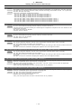
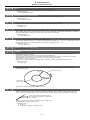
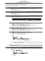
T10 Fin wait 0ooo
Details
The following Nos. are shown during the operation of the corresponding completion wait factor. The numbers will disappear when the operation is completed.
The completion wait factor is indicated with four digits (in hexadecimal).
Bit allocation of the 4-digit hexadecimal message is as follows.
bit F:
bit E:
bit D:
bit C: Waiting for high-speed synchronous tapping preparation to be completed (Note 1)
bit B: Unclamp signal wait (Note 2)
bit A: Waiting for synchronous tap hole bottom in-position check to be completed. (Note 4)
bit 9:
bit 8: In dwell execution
bit 7: Door open (Note 3)
bit 6:
bit 5:
bit 4: Waiting for spindle position to be looped
bit 3: Waiting for spindle orientation to be completed
bit 2: Waiting for cutting speed deceleration
bit 1: Waiting for rapid traverse deceleration
bit 0: Waiting for MSTB completion
(Note 1) In case high-speed synchronous tapping won't turn ready while MS Configurator is in
use, reset the NC to release the alarm. If MS Configurator is not in use and still highspeed tapping preparation won't be completed, contact the service center.
(Note 2) This shows the wait state for the unclamp signal's ON/OFF for the index table indexing.
(Note 3) This shows the door open state caused by the door interlock function.
(Note 4) There may be a case that this operation does not complete because the high-speed
synchronous tapping is enabled and the hole bottom in-position width is extremely small.
In this case, reset to cancel the alarm.
Avoid setting the hole bottom width to extremely small value (e.g. 0.001) during the highspeed synchronous tapping.
I-9
I Alarms
Servo/Spindle Alarms (S)
3. Servo/Spindle Alarms (S)
Axis names are expressed with a letter in the following manner:
- NC axis: axis name defined by the parameter
- Spindle: "S" = the 1st spindle, "T" = the 2nd spindle, "M" = the 3rd spindle, "N" = the 4th spindle, "P" = the
5th spindle, "Q" = the 6th spindle, "R" = the 7th spindle
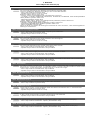
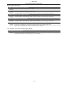
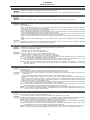
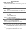
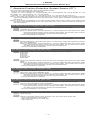
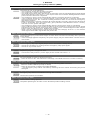
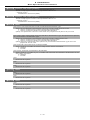
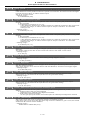
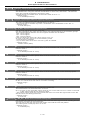
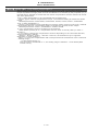
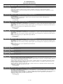
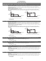
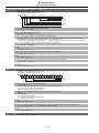
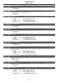
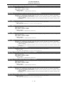
3.1 Servo Errors (S01/S03/S04)
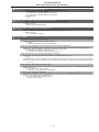
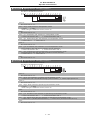
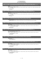
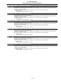
Servo alarm is displayed in the following format.
S
Axis name
Error No.
Reset method
Message
Alarm class
Alarm class
Message
Reset method
Resetting methods
S01
Servo alarm
PR
After removing the cause of the alarm, reset
the alarm by turning the NC power ON
again.
S03
Servo alarm
NR
After removing the cause of the alarm, reset
the alarm by inputting the NC RESET key.
S04
Servo alarm
AR
After removing the cause of the alarm, reset
the alarm by turning the drive unit power ON
again.
Error No. consists of four digits (0010 to). Servo alarms are explained in ascending order of the error No.
The four digits on the left part of each alarm indicate the error No.
(Note 1) For the details of servo alarms, refer to your drive unit's instruction manual.
(Note 2) PR alarms 005B, 005D, and 005E can be released by pressing the reset button. Upon completion
of releasing a safety observation alarm by pressing the reset button, the alarm of the highest priority of
the remaining will be displayed.
Drive unit alarms
0010 Insufficient voltage
Details
A drop of bus voltage was detected in main circuit.
- Servo stop method: Dynamic stop
- Spindle stop method: Coast to a stop
0011 Axis selection error
Details
The axis selection rotary switch has been incorrectly set.
- Servo stop method: Initial error
- Spindle stop method: Initial error
0012 Memory error 1
Details
A hardware error was detected during the power ON self-check.
- Servo stop method: Initial error
- Spindle stop method: Initial error
0013 Software processing error 1
Details
An error was detected for the software execution state.
- Servo stop method: Dynamic stop
- Spindle stop method: Coast to a stop
0014 Software processing error 2
Details
The current processing processor does not operate correctly.
- Servo stop method: Dynamic stop
- Spindle stop method: Coast to a stop
0016 Init mag pole pos detect err
Details
In the built-in motor which uses the absolute position detector, the servo ON has been set before the magnetic pole shift amount is set.
The magnetic pole position, detected in the initial magnetic pole position detection control, is
not correctly set.
- Servo stop method: Dynamic stop
- Spindle stop method: Coast to a stop
I - 10
I Alarms
Servo/Spindle Alarms (S)
0017 A/D converter error
Details
A current feedback error was detected.
- Servo stop method: Dynamic stop
- Spindle stop method: Coast to a stop
0018 Motor side dtc: Init commu err
Details
An error was detected in the initial communication with the motor side detector.
- Servo stop method: Initial error
- Spindle stop method: Initial error
0019 Detector commu err in syn cont
Details
An error of the shared detector on the machine side was detected on the secondary axis of
the speed command synchronization control.
- Servo stop method: Dynamic stop
001A Machine side dtc: Init comu er
Details
An error was detected in the initial communication with the machine side detector.
- Servo stop method: Initial error
- Spindle stop method: Initial error
001B Machine side dtc: Error 1
Details
An error was detected by the detector connected to the machine side.
The error details are different according to the detector type.
- Servo stop method: Dynamic stop
- Spindle stop method: Coast to a stop
[Detector alarm (Servo drive unit)]
- OSA105, OSA105ET2A, OSA166, OSA166ET2NA(MITSUBISHI) Memory alarm
- OSA18() CPU alarm
- MDS-B-HR() Memory error
- MBA405W(MITSUBISHI) CPU error
- AT343, AT543, AT545(Mitsutoyo) Initialization error
- LC193M, LC493M, LC195M, LC495M, RCN223M, RCN227M, RCN727M, RCN827M, EIB
Series(HEIDENHAIN) Initialization error
- MPRZ Scale(MHI) Installation accuracy fault
- SR75, SR85, SR77, SR87, RU77(Magnescale) Laser diode error
- RL40N Series(Renishaw) Initialization error
[Detector alarm (Spindle drive unit)]
- TS5690, TS5691(MITSUBISHI) Memory error
- MDS-B-HR() Initialization error
- OSA18() CPU error
- MBE405W(MITSUBISHI) CPU error
- EIB Series(HEIDENHAIN) Initialization error
- MPCI scale(MHI) Installation accuracy fault
(Note) A driver processes all reset types of alarms as "PR". However, "AR" will be applied according to the detector.
001C Machine side dtc: Error 2
Details
An error was detected by the detector connected to the machine side.
The error details are different according to the detector type.
- Servo stop method: Dynamic stop
- Spindle stop method: Coast to a stop
[Detector alarm (Servo drive unit)]
- OSA105, OSA105ET2A, OSA166, OSA166ET2NA(MITSUBISHI) LED alarm
- MBA405W(MITSUBISHI) Waveform error
- AT343, AT543, AT545(Mitsutoyo) EEPROM error
- LC193M, LC493M, LC195M, LC495M, RCN223M, RCN227M, RCN727M, RCN827M, EIB
Series(HEIDENHAIN) EEPROM error
- SR75, SR85, SR77, SR87, RU77(Magnescale) System memory error
[Detector alarm (Spindle drive unit)]
- TS5690, TS5691(MITSUBISHI) Waveform error
- MBE405W(MITSUBISHI) Waveform error
- EIB Series(HEIDENHAIN) EEPROM error
(Note) A driver processes all reset types of alarms as "PR". However, "AR" will be applied according to the detector.
I - 11
I Alarms
Servo/Spindle Alarms (S)
001D Machine side dtc: Error 3
Details
An error was detected by the detector connected to the machine side.
The error details are different according to the detector type.
- Servo stop method: Dynamic stop
- Spindle stop method: Coast to a stop
[Detector alarm (Servo drive unit)]
- OSA105, OSA105ET2A, OSA166, OSA166ET2NA(MITSUBISHI) Data alarm
- OSA18() Data alarm
- MDS-B-HR() Data error
- MBA405W(MITSUBISHI) Data error
- AT343, AT543, AT545(Mitsutoyo) Photoelectric type, static capacity type data mismatch
- LC193M, LC493M, LC195M, LC495M, RCN223M, RCN227M, RCN727M, RCN827M, EIB
Series(HEIDENHAIN) Relative/ absolute position data mismatch
- MPRZ Scale(MHI) Detection position deviance
- SR75, SR85, SR77, SR87, RU77(Magnescale) Encoder mismatch error
- SAM/SVAM/GAM/LAN Series (FAGOR) Absolute position detection error
- RL40N Series (Renishaw) Absolute position data error
[Detector alarm (Spindle drive unit)]
- MDS-B-HR() Data error
- OSA18() Data error
- MBE405W(MITSUBISHI) Data error
- MPCI scale(MHI) Detection position deviance
(Note) A driver processes all reset types of alarms as "PR". However, "AR" will be applied according to the detector.
001E Machine side dtc: Error 4
Details
An error was detected by the detector connected to the machine side.
The error details are different according to the detector type.
- Servo stop method: Dynamic stop
- Spindle stop method: Coast to a stop
[Detector alarm (Servo drive unit)]
- AT343, AT543, AT545(Mitsutoyo) ROM/RAM error
- LC193M, LC493M, LC195M, LC495M, RCN223M, RCN227M, RCN727M, RCN827M, EIB
Series(HEIDENHAIN) ROM/RAM error
- MPRZ Scale(MHI) Scale breaking
- SAM/SVAM/GAM/LAM Series (FAGOR) H/W error
[Detector alarm (Spindle drive unit)]
- MPCI scale(MHI) Scale breaking
(Note) A driver processes all reset types of alarms as "PR". However, "AR" will be applied according to the detector.
001F Machine side dtc: Commu error
Details
An error was detected in the communication with the machine side detector.
- Servo stop method: Dynamic stop
- Spindle stop method: Coast to a stop
0021 Machine side dtc: No signal
Details
In the machine side detector, ABZ-phase feedback cannot be returned even when the motor
moves.
- Servo stop method: Dynamic stop
- Spindle stop method: Coast to a stop
0022 Detector data error
Details
An error was detected in the feedback data from the position detector.
- Servo stop method: Dynamic stop
0023 Excessive speed error
Details
The state that there is a difference between the actual speed and command speed continued
for longer than the excessive speed deviation timer setting.
- Spindle stop method: Coast to a stop
0024 Grounding
Details
The motor power cable is in contact with FG (Frame Ground).
- Servo stop method: Dynamic stop
- Spindle stop method: Coast to a stop
0025 Absolute position data lost
Details
The absolute position data was lost in the detector.
- Servo stop method: Initial error
0026 Unused axis error
Details
In the multi-axis drive unit, there is an axis set to free, and the other axis detected a power
module error.
- Servo stop method: Dynamic stop
- Spindle stop method: Coast to a stop
I - 12
I Alarms
Servo/Spindle Alarms (S)
0027 Machine side dtc: Error 5
Details
An error was detected by the detector connected to the machine side.
The error details are different according to the detector type.
- Servo stop method: Dynamic stop
- Spindle stop method: Coast to a stop
[Detector alarm (Servo drive unit)]
- MDS-B-HR() Scale not connected
- AT343, AT543, AT545(Mitsutoyo) CPU error
- LC193M, LC493M, LC195M, LC495M, RCN223M, RCN227M, RCN727M, RCN827M, EIB
Series(HEIDENHAIN) CPU error
- MPRZ Scale(MHI) Absolute value detection fault
- SAM/SVAM/GAM/LAN Series (FAGOR) CPU error
[Detector alarm (Spindle drive unit)]
- MDS-B-HR() Connection error
- EIB Series(HEIDENHAIN) CPU error
(Note) A driver processes all reset types of alarms as "PR". However, "AR" will be applied according to the detector.
0028 Machine side dtc: Error 6
Details
An error was detected by the detector connected to the machine side.
The error details are different according to the detector type.
- Servo stop method: Dynamic stop
- Spindle stop method: Coast to a stop
[Detector alarm (Servo drive unit)]
- AT343, AT543, AT545(Mitsutoyo) Photoelectric type overspeed
- LC193M, LC493M, LC195M, LC495M, RCN223M, RCN227M, RCN727M, RCN827M, EIB
Series(HEIDENHAIN) Overspeed
- SR75, SR85, SR77, SR87, RU77(Magnescale) Over speed
- RL40N Series (Renishaw) Overspeed error
[Detector alarm (Spindle drive unit)]
- TS5690, TS5691(MITSUBISHI) Overspeed
- EIB Series(HEIDENHAIN) Overspeed
(Note) A driver processes all reset types of alarms as "PR". However, "AR" will be applied according to the detector.
0029 Machine side dtc: Error 7
Details
An error was detected by the detector connected to the machine side.
The error details are different according to the detector type.
- Servo stop method: Dynamic stop
- Spindle stop method: Coast to a stop
[Detector alarm (Servo drive unit)]
- AT343, AT543, AT545(Mitsutoyo) Static capacity type error
- LC193M, LC493M, LC195M, LC495M, RCN223M, RCN227M, RCN727M, RCN827M, EIB
Series(HEIDENHAIN) Absolute position data error
- MPRZ Scale(MHI) Gain fault
- SR75, SR85, SR77, SR87, RU77(Magnescale) Absolute position data error
[Detector alarm (Spindle drive unit)]
- MPCI scale(MHI) Gain fault
(Note) A driver processes all reset types of alarms as "PR". However, "AR" will be applied according to the detector.
002A Machine side dtc: Error 8
Details
An error was detected by the detector connected to the machine side.
The error details are different according to the detector type.
- Servo stop method: Dynamic stop
- Spindle stop method: Coast to a stop
[Detector alarm (Servo drive unit)]
- MBA405W(MITSUBISHI) Count error
- AT343, AT543, AT545(Mitsutoyo) Photoelectric type error
- LC193M, LC493M, LC195M, LC495M, RCN223M, RCN227M, RCN727M, RCN827M, EIB
Series(HEIDENHAIN) Relative position data error
- MPRZ Scale(MHI) Phase fault
- SR75, SR85, SR77, SR87, RU77(Magnescale) Relative position data error
[Detector alarm (Spindle drive unit)]
- TS5690, TS5691(MITSUBISHI) Relative position data error
- MBE405W(MITSUBISHI) Count error
- EIB Series(HEIDENHAIN) Relative position data error
- MPCI scale(MHI) Phase fault
(Note) A driver processes all reset types of alarms as "PR". However, "AR" will be applied according to the detector.
I - 13
I Alarms
Servo/Spindle Alarms (S)
002B Motor side dtc: Error 1
Details
An error was detected by the detector connected to the motor side.
The error details are different according to the detector type.
- Servo stop method: Dynamic stop
- Spindle stop method: Coast to a stop
[Detector alarm (Servo drive unit)]
- OSA105, OSA105ET2A, OSA166, OSA166ET2NA(MITSUBISHI) Memory alarm
- OSA18() CPU alarm
- MDS-B-HR() Memory error
- AT343, AT543, AT545(Mitsutoyo) Initialization error
- LC193M, LC493M, RCN223M, RCN227M, RCN727M, RCN827M, EIB Series(HEIDENHAIN) Initialization error
- MPRZ Series(MHI) Installation accuracy fault
- SR75, SR85, SR77, SR87, RU77(Magnescale) Laser diode error
[Detector alarm (Spindle drive unit)]
- TS5690, TS5691(MITSUBISHI) Memory error
- MDS-B-HR() Initialization error
- OSA18() CPU error
- EIB Series(HEIDENHAIN) Initialization error
- MPCI scale(MHI) Installation accuracy fault
(Note) A driver processes all reset types of alarms as "PR". However, "AR" will be applied according to the detector.
002C Motor side dtc: Error 2
Details
An error was detected by the detector connected to the motor side.
The error details are different according to the detector type.
- Servo stop method: Dynamic stop
- Spindle stop method: Coast to a stop
[Detector alarm (Servo drive unit)]
- OSA105, OSA105ET2A, OSA166, OSA166ET2NA(MITSUBISHI) LED alarm
- AT343, AT543, AT545(Mitsutoyo) EEPROM error
- LC193M, LC493M, RCN223M, RCN227M, RCN727M, RCN827M, EIB Series(HEIDENHAIN) EEPROM error
- SR75, SR85, SR77, SR87, RU77(Magnescale) System memory error
[Detector alarm (Spindle drive unit)]
- TS5690, TS5691(MITSUBISHI) Waveform error
- EIB Series(HEIDENHAIN) EEPROM error
(Note) A driver processes all reset types of alarms as "PR". However, "AR" will be applied according to the detector.
002D Motor side dtc: Error 3
Details
An error was detected by the detector connected to the motor side.
The error details are different according to the detector type.
- Servo stop method: Dynamic stop
- Spindle stop method: Coast to a stop
[Detector alarm (Servo drive unit)]
- OSA105, OSA105ET2A, OSA166, OSA166ET2NA(MITSUBISHI) Data alarm
- OSA18() Data alarm
- MDS-B-HR() Data error
- AT343, AT543, AT545(Mitsutoyo) Photoelectric type, static capacity type data mismatch
- LC193M, LC493M, RCN223M, RCN227M, RCN727M, RCN827M, EIB Series(HEIDENHAIN) Relative/ absolute position data mismatch
- MPRZ Series(MHI) Detection position deviance
- SR75, SR85, SR77, SR87, RU77(Magnescale) Encoder mismatch error
- SAM/SVAM/GAM/LAN Series (FAGOR) Absolute position detection error
[Detector alarm (Spindle drive unit)]
- MDS-B-HR() Data error
- OSA18() Data error
- MPCI scale(MHI) Detection position deviance
(Note) A driver processes all reset types of alarms as "PR". However, "AR" will be applied according to the detector.
002E Motor side dtc: Error 4
Details
An error was detected by the detector connected to the motor side.
The error details are different according to the detector type.
- Servo stop method: Dynamic stop
- Spindle stop method: Coast to a stop
[Detector alarm (Servo drive unit)]
- AT343, AT543, AT545(Mitsutoyo) ROM/RAM error
- LC193M, LC493M, RCN223M, RCN227M, RCN727M, RCN827M, EIB Series(HEIDENHAIN) ROM/RAM error
- MPRZ Series(MHI) Scale breaking
- SAM/SVAM/GAM/LAM Series (FAGOR) H/W error
[Detector alarm (Spindle drive unit)]
- MPCI scale(MHI) Scale breaking
(Note) A driver processes all reset types of alarms as "PR". However, "AR" will be applied according to the detector.
002F Motor side dtc: Commu error
Details
An error was detected in the communication with the motor side detector.
- Servo stop method: Dynamic stop
- Spindle stop method: Coast to a stop
0030 Over regeneration
Details
Over-regeneration level exceeded 100%. The regenerative resistor is overloaded.
- Servo stop method: Dynamic stop
- Spindle stop method: Coast to a stop
I - 14
I Alarms
Servo/Spindle Alarms (S)
0031 Overspeed
Details
The motor speed exceeded the allowable speed.
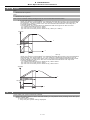
- Servo stop method: Deceleration stop enabled
- Spindle stop method: Deceleration stop enabled
0032 Power module overcurrent
Details
The power module detected the overcurrent.
- Servo stop method: Dynamic stop
- Spindle stop method: Coast to a stop
0033 Overvoltage
Details
The bus voltage in main circuit exceeded the allowable value.
- Servo stop method: Dynamic stop
- Spindle stop method: Coast to a stop
0034 NC-DRV commu: CRC error
Details
The data received from the NC was outside the setting range.
- Servo stop method: Deceleration stop enabled
- Spindle stop method: Deceleration stop enabled
0035 NC command error
Details
The travel command data received from the NC was excessive.
- Servo stop method: Deceleration stop enabled
- Spindle stop method: Deceleration stop enabled
0036 NC-DRV commu: Commu error
Details
The communication with the NC was interrupted.
- Servo stop method: Deceleration stop enabled
- Spindle stop method: Deceleration stop enabled
0037 Initial parameter error
Details
An incorrect set value was detected among the parameters send from the NC at the power
ON.
In the SLS (Safely Limited Speed) function, an error was detected in the relation between the
safety speed and safety rotation number in the speed observation mode.
- Servo stop method: Initial error
- Spindle stop method: Initial error
0038 NC-DRV commu: Protocol error 1
Details
An error was detected in the communication frames received from the NC.
Or, removing an axis or changing an axis was performed in the synchronous control.
- Servo stop method: Deceleration stop enabled
- Spindle stop method: Deceleration stop enabled
0039 NC-DRV commu: Protocol error 2
Details
An error was detected in the axis data received from the NC.
Or, in changing an axis, the parameter setting of the synchronous control was applied when
the axis was installed.
- Servo stop method: Deceleration stop enabled
- Spindle stop method: Deceleration stop enabled
003A Overcurrent
Details
Excessive motor drive current was detected.
- Servo stop method: Dynamic stop
- Spindle stop method: Coast to a stop
003B Power module overheat
Details
The power module detected an overheat.
- Servo stop method: Dynamic stop
- Spindle stop method: Coast to a stop
003C Regeneration circuit error
Details
An error was detected in the regenerative transistor or in the regenerative resistor.
- Servo stop method: Dynamic stop
003D Pw sply volt err acc/dec
Details
A motor control error during acceleration/deceleration, due to a power voltage failure, was detected.
- Servo stop method: Dynamic stop
003E Magnet pole pos detect err
Details
The magnetic pole position, detected in the magnetic pole position detection control, is not correctly detected.
- Servo stop method: Dynamic stop
- Spindle stop method: Coast to a stop
I - 15
I Alarms
Servo/Spindle Alarms (S)
0041 Feedback error 3
Details
Either a missed feedback pulse in the motor side detector or an error in the Z-phase was detected in the full closed loop system.
- Servo stop method: Dynamic stop
- Spindle stop method: Coast to a stop
0042 Feedback error 1
Details
Either a missed feedback pulse in the position detection or an error in the Z-phase was detected. Or the distance-coded reference check error exceeded the allowable value when the distance-coded reference scale was used.
- Servo stop method: Dynamic stop
- Spindle stop method: Coast to a stop
0043 Feedback error 2
Details
An excessive difference in feedback was detected between the machine side detector and the
motor side detector.
- Servo stop method: Dynamic stop
- Spindle stop method: Coast to a stop
0045 Fan stop
Details
An overheat of the power module was detected during the cooling fan stopping.
- Servo stop method: Dynamic stop
- Spindle stop method: Coast to a stop
0046 Motor overheat
Details
Either the motor or the motor side detector detected an overheat.
Or, the thermistor signal receiving circuit of the linear motor or DD motor was disconnected.
Or, the thermistor signal receiving circuit was short-circuited.
- Servo stop method: Deceleration stop enabled
- Spindle stop method: Deceleration stop enabled
0048 Motor side dtc: Error 5
Details
An error was detected by the detector connected to the main side.
The error details are different according to the connected detector.
- Servo stop method: Dynamic stop
- Spindle stop method: Coast to a stop
[Detector alarm (Servo drive unit)]
- MDS-B-HR() Scale not connected
- AT343, AT543, AT545(Mitsutoyo) CPU error
- LC193M, LC493M, RCN223M, RCN227M, RCN727M, RCN827M, EIB Series(HEIDENHAIN) CPU error
- MPRZ Series(MHI) Absolute value detection fault
- SAM/SVAM/GAM/LAM Series (FAGOR) CPU error
[Detector alarm (Spindle drive unit)]
- MDS-B-HR() Connection error
- EIB Series(HEIDENHAIN) CPU error
(Note) A driver processes all reset types of alarms as "PR". However, "AR" will be applied according to the detector.
0049 Motor side dtc: Error 6
Details
An error was detected by the detector connected to the main side.
The error details are different according to the connected detector.
- Servo stop method: Dynamic stop
- Spindle stop method: Coast to a stop
[Detector alarm (Servo drive unit)]
- AT343, AT543, AT545(Mitsutoyo) Photoelectric type overspeed
- LC193M, LC493M, RCN223M, RCN227M, RCN727M, RCN827M, EIB Series(HEIDENHAIN) Overspeed
- SR75, SR85, SR77, SR87, RU77(Magnescale) Over speed
[Detector alarm (Spindle drive unit)]
- TS5690, TS5691(MITSUBISHI) Overspeed
- EIB Series(HEIDENHAIN) Overspeed
(Note) A driver processes all reset types of alarms as "PR". However, "AR" will be applied according to the detector.
004A Motor side dtc: Error 7
Details
An error was detected by the detector connected to the main side.
The error details are different according to the connected detector.
- Servo stop method: Dynamic stop
- Spindle stop method: Coast to a stop
[Detector alarm (Servo drive unit)]
- AT343, AT543, AT545(Mitsutoyo) Static capacity type error
- LC193M, LC493M, RCN223M, RCN227M, RCN727M, RCN827M, EIB Series(HEIDENHAIN) Absolute position data error
- MPRZ Series(MHI) Gain fault
- SR75, SR85, SR77, SR87, RU77(Magnescale) Absolute position data error
[Detector alarm (Spindle drive unit)]
- MPCI scale(MHI) Gain fault
(Note) A driver processes all reset types of alarms as "PR". However, "AR" will be applied according to the detector.
I - 16
I Alarms
Servo/Spindle Alarms (S)
004B Motor side dtc: Error 8
Details
An error was detected by the detector connected to the main side.
The error details are different according to the connected detector.
- Servo stop method: Dynamic stop
- Spindle stop method: Coast to a stop
[Detector alarm (Servo drive unit)]
- AT343, AT543, AT545(Mitsutoyo) Photoelectric type error
- LC193M, LC493M, RCN223M, RCN227M, RCN727M, RCN827M, EIB Series(HEIDENHAIN) Relative position data error
- MPRZ Series(MHI) Phase fault
- SR75, SR85, SR77, SR87, RU77(Magnescale) Relative position data error
[Detector alarm (Spindle drive unit)]
- TS5690, TS5691(MITSUBISHI) Relative position data error
- EIB Series(HEIDENHAIN) Relative position data error
- MPCI scale(MHI) Phase fault
(Note) A driver processes all reset types of alarms as "PR". However, "AR" will be applied according to the detector.
004C Current err mag pole estim
Details
Current detection failed at the initial magnetic pole estimation.
- Servo stop method: Dynamic stop
- Spindle stop method: Coast to a stop
004D Dual signal error
Details
An error was detected in the signal related to the dual signal.
- Servo stop method: Dynamic stop
- Spindle stop method: Coast to a stop
004E NC command mode error
Details
An error was detected in the control mode send from the NC.
- Servo stop method: Deceleration stop enabled
- Spindle stop method: Deceleration stop enabled
004F Instantaneous power interrupt
Details
The control power supply has been shut down for 50ms or more.
- Servo stop method: Deceleration stop enabled
- Spindle stop method: Deceleration stop enabled
0050 Overload 1
Details
Overload detection level became 100% or more. The motor or the drive unit is overloaded.
- Servo stop method: Deceleration stop enabled
- Spindle stop method: Deceleration stop enabled
0051 Overload 2
Details
In a servo system, current command of 95% or more of the unit’s max. current was given continuously for 1 second or longer. In a spindle system, current command of 95% or more of the
motor’s max. current was given continuously for 1 second or longer.
- Servo stop method: Deceleration stop enabled
- Spindle stop method: Deceleration stop enabled
0052 Excessive error 1
Details
A position tracking error during servo ON was excessive.
- Servo stop method: Deceleration stop enabled
- Spindle stop method: Deceleration stop enabled
0053 Excessive error 2
Details
A position tracking error during servo OFF was excessive.
- Servo stop method: Dynamic stop
0054 Excessive error 3
Details
There was no motor current feedback when the alarm "Excessive error 1" was detected.
- Servo stop method: Dynamic stop
- Spindle stop method: Coast to a stop
0056 Commanded speed error
Details
In the C-axis control mode, excessive speed error was detected.
- Spindle stop method: Deceleration stop enabled
0058 Collision detection 1: G0
Details
A disturbance torque exceeded the allowable value in rapid traverse modal (G0).
- Servo stop method: Maximum capacity deceleration stop
0059 Collision detection 1: G1
Details
A disturbance torque exceeded the allowable value in the cutting feed modal (G1).
- Servo stop method: Maximum capacity deceleration stop
I - 17
I Alarms
Servo/Spindle Alarms (S)
005A Collision detection 2
Details
A current command with the maximum drive unit current value was detected.
- Servo stop method: Maximum capacity deceleration stop
005B Safely limited: Cmd spd err
Details
A commanded speed exceeding the safely limited speed was detected in the safely limited
mode.
- Servo stop method: Deceleration stop enabled
- Spindle stop method: Deceleration stop enabled
005D Safely limited: Door stat err
Details
The door state signal input in the NC does not coincide with the door state signal input in the
drive unit in the safely limited mode. Otherwise, door open state was detected in normal mode.
- Servo stop method: Deceleration stop enabled
- Spindle stop method: Deceleration stop enabled
005E Safely limited: FB speed err
Details
A motor speed exceeding the safely limited speed was detected in the safely limited mode.
- Servo stop method: Deceleration stop enabled
- Spindle stop method: Deceleration stop enabled
005F External contactor error
Details
A contact of the external contactor is welding.
- Servo stop method: Deceleration stop enabled
- Spindle stop method: Deceleration stop enabled
0080 Motor side dtc: cable err
Details
The cable type of the motor side detector cable is for rectangular wave signal.
- Servo stop method: Initial error
0081 Machine side dtc: cable err
Details
The cable type of the machine side detector cable does not coincide with the detector type
which is set by the parameter.
- Servo stop method: Initial error
0087 Drive unit communication error
Details
The communication frame between drive units was aborted.
- Servo stop method: Dynamic stop
- Spindle stop method: Coast to a stop
0088 Watchdog
Details
The drive unit does not operate correctly.
- Servo stop method: Dynamic stop
- Spindle stop method: Coast to a stop
008A Drivers commu data error 1
Details
The communication data 1 between drivers exceeded the tolerable value in the communication between drive units.
- Servo stop method: Dynamic stop
- Spindle stop method: Coast to a stop
008B Drivers commu data error 2
Details
The communication data 2 between drivers exceeded the tolerable value in the communication between drive units.
- Servo stop method: Dynamic stop
- Spindle stop method: Coast to a stop
I - 18
I Alarms
Servo/Spindle Alarms (S)
Power supply alarms
0061 Pw sply: Pwr module overcurnt
Details
Overcurrent protection function in the power module has started its operation.
0062 Pw sply: Frequency error
Details
The input power supply frequency increased above the specification range.
0066 Pw sply: Process error
Details
An error occurred in the process cycle.
0067 Pw sply: Phase interruption
Details
An open-phase condition was detected in input power supply circuit.
0068 Pw sply: Watchdog
Details
The system does not operate correctly.
0069 Pw sply: Grounding
Details
The motor power cable is in contact with FG (Frame Ground).
006A Pw sply: Ext contactor weld
Details
A contact of the external contactor is welding.
006B Pw sply: Rush circuit error
Details
An error was detected in the rush circuit.
006C Pw sply: Main circuit error
Details
An error was detected in charging operation of the main circuit capacitor.
006D Pw sply: Parameter error
Details
An error was detected in the parameter sent from the drive unit.
006E Pw sply: H/W error
Details
An error was detected in the internal memory.
An error was detected in the A/D converter.
An error was detected in the unit identification.
006F Power supply error
Details
No power supply is connected to the drive unit, or a communication error was detected.
0070 Pw sply: External EMG stop err
Details
A mismatch of the external emergency stop input and NC emergency stop input continued for
30 seconds.
0071 Pw sply: Instant pwr interrupt
Details
The power was momentarily interrupted.
0072 Pw sply: Fan stop
Details
A cooling fan built in the power supply unit stopped, and overheat occurred in the power module.
0073 Pw sply: Over regeneration
Details
Over-regeneration detection level became over 100%. The regenerative resistor is overloaded. This alarm cannot be reset for 15 min from the occurrence to protect the regeneration resistor. Leave the drive system energized for more than 15 min, then turn the power ON to
reset the alarm.
0074 Pw sply: Option unit error
Details
An alarm was detected in the power backup unit (power supply option unit).
Check the LED display on the power backup unit to identify what alarm is occurring to the unit.
Refer to the instruction manual of your drive unit for details.
0075 Pw sply: Overvoltage
Details
L+ and L- bus voltage in main circuit exceeded the allowable value. As the voltage between
L+ and L- is high immediately after this alarm, another alarm may occur if this alarm is reset
in a short time. Wait more than 5 min before resetting so that the voltage drops.
0076 Pw sply: Function setting err
Details
The rotary switch setting of external emergency stop is not correct, or a wrong external emergency stop signal is input.
Undefined number was selected for the rotary switch setting of the power supply.
I - 19
I Alarms
Servo/Spindle Alarms (S)
0077 Pw sply: Power module overheat
Details
Thermal protection function in the power module has started its operation.
I - 20
I Alarms
Servo/Spindle Alarms (S)
3.2 Initial Parameter Errors (S02)
S02 Initial parameter error:PR 2201-2456 (Axis name)
Details
Remedy
The servo parameter setting data is illegal.
The alarm No. is the No. of the servo parameter where the error occurred.
Check the descriptions for the appropriate servo parameters and correct them.
Even when the parameter is set to a value within the setting range, an error is occurring due
to the hardware compatibility or specifications or in relation to several other parameters.
Refer to "Parameter Numbers during Initial Parameter Error" of each drive unit instruction
manual for details.
S02 Initial parameter error:PR 13001-13256 (Axis name)
Details
Remedy
Parameter error
The spindle parameter setting data is illegal.
The alarm No. is the No. of the spindle parameter where the error occurred.
Check the descriptions for the appropriate spindle parameters and correct them.
Even when the parameter is set to a value within the setting range, an error is occurring due
to the hardware compatibility or specifications or in relation to several other parameters.
Refer to "Parameter Numbers during Initial Parameter Error" of each drive unit instruction
manual for details.
3.3 Safety Function Errors (S05)
S05 SAFETY FUNC ALM
Details
Remedy
The STO signal has been input through the CN8 connector.
Make sure that a short-circuiting connector has been inserted into CN8.
I - 21
I Alarms
Servo/Spindle Alarms (S)
3.4 Parameter Errors (S51)
S51 Parameter error 2201-2456 (Axis name)
Details
Remedy
Servo parameter setting data is illegal.
The alarm No. is the No. of the servo parameter where the warning occurred.
Check the descriptions for the appropriate servo parameters and correct them.
Even when the parameter is set to a value within the setting range, an error is occurring due
to the hardware compatibility or specifications or in relation to several other parameters.
Refer to "Parameter Numbers during Initial Parameter Error" of each drive unit instruction
manual for details.
S51 Parameter error 13001-13256 (Axis name)
Details
Remedy
Spindle parameter setting data is illegal.
The alarm No. is the No. of the spindle parameter where the warning occurred.
Check the descriptions for the appropriate spindle parameters and correct them.
Even when the parameter is set to a value within the setting range, an error is occurring due
to the hardware compatibility or specifications or in relation to several other parameters.
Refer to "Parameter Numbers during Initial Parameter Error" of each drive unit instruction
manual for details.
I - 22
I Alarms
Servo/Spindle Alarms (S)
3.5 Servo Warnings (S52)
Servo warning is displayed in the following format.
S
Axis name
Error No.
Message
Alarm class
Alarm class
S52
Message
Servo warning
Error No. consists of four digits (0096 to). Servo warnings are explained in ascending order of the error No.
The four digits on the left part of each warning indicate the error No.
(Note) For the details of servo warnings, refer to your drive unit's instruction manual.
Drive unit warnings
0096 Scale feedback error
Details
An excessive difference in feedback amount was detected between the main side detector
and the MPI scale in MPI scale absolute position detection system.
- Reset method: Automatically reset once the cause of the warning is removed.
0097 Scale offset error
Details
An error was detected in the offset data that is read at the NC power-ON in MPI scale absolute
position detection system.
009B Detec cnv: Mag pole shift warn
Details
The difference between the magnetic pole position after the phase Z has been passed (magnetic pole shift amount:SV028) and the initially detected position is excessive in the built-in
motor's incremental control system. The magnetic pole is controlled by the initial detection value.
- Reset method: Automatically reset once the cause of the warning is removed.
009E Abs pos dtc: Rev count error
Details
An error was detected in the revolution counter data of the absolute position detector. The accuracy of absolute position is not guaranteed.
- Reset method: Automatically reset once the cause of the warning is removed.
009F Battery voltage drop
Details
The battery voltage to be supplied to the absolute position detector is dropping.
00A3 In initial setup of ABS posn.
Details
This warning is detected until the axis reaches the reference position during the initial setup
of the distance-coded reference check function. This warning turns OFF after the axis has
reached the position, thus set the value displayed on the drive monitor to the parameter.
This warning is detected during the initial setup of MBA405W. This warning turns OFF after
the initial setup is completed by having the axis pass the Z-phase of MBA405W and turning
the NC power ON again.
- Reset method: Automatically reset once the cause of the warning is removed.
00A4 Dual signal warning
Details
An input was detected in the signal related to the dual signal.
- Reset method: Automatically reset once the cause of the warning is removed.
00A6 Fan stop warning
Details
A cooling fan in the drive unit stopped.
- Reset method: Automatically reset once the cause of the warning is removed.
00E0 Over regeneration warning
Details
Over-regeneration detection level exceeded 80%.
- Reset method: Automatically reset once the cause of the warning is removed.
00E1 Overload warning
Details
A level of 80% of the Overload 1 alarm state was detected.
- Reset method: Automatically reset once the cause of the warning is removed.
I - 23
I Alarms
Servo/Spindle Alarms (S)
00E4 Set parameter warning
Details
An incorrect set value was detected among the parameters send from the NC in the normal
operation.
- Reset method: Automatically reset once the cause of the warning is removed.
00E6 Control axis detach warning
Details
A control axis is being detached. (State display)
- Reset method: Automatically reset once the cause of the warning is removed.
00E7 In NC emergency stop state
Details
In NC emergency stop. (State display)
- Stop method: Deceleration stop enabled
- Reset method: Automatically reset once the cause of the warning is removed.
00E8-00EF Power supply warning
Details
The power supply unit detected a warning. The error details are different according to the connected power supply unit.
Refer to "Power supply warning".
- Stop method: - (EA: Deceleration stop enabled)
- Reset method: Automatically reset once the cause of the warning is removed.
I - 24
I Alarms
Servo/Spindle Alarms (S)
Power supply warnings
00E9 Instant pwr interrupt warning
Details
The power was momentarily interrupted.
00EA In external EMG stop state
Details
External emergency stop signal was input.
- Reset method: Automatically reset once the cause of the warning is removed.
00EB Pw sply: Over regenerat warn
Details
Over-regeneration detection level exceeded 80%.
- Reset method: Automatically reset once the cause of the warning is removed.
00EE Pw sply: Fan stop warning
Details
A cooling fan built in the power supply unit stopped.
- Reset method: Automatically reset once the cause of the warning is removed.
00EF Pw sply: Option unit warning
Details
A warning is detected in the power backup unit (power supply option unit).
Check the LED display on the power backup unit to identify what alarm is occurring to the unit.
Refer to the using drive unit instruction manual for details.
3.6 Safety Function Warnings (S53)
S53 SAFETY FUNC WRG
Details
The system has been set in the STO state.
The STO state is also entered at the time of emergency stop, but in this case, this warning will
not appear because the emergency stop has priority.
I - 25
I Alarms
MCP Alarms (Y)
4. MCP Alarms (Y)
Axis names are expressed with a letter in the following manner:
- NC axis: axis name defined by the parameter
- Spindle: "S" = the 1st spindle, "T" = the 2nd spindle, "M" = the 3rd spindle, "N" = the 4th spindle, "P" = the
5th spindle, "Q" = the 6th spindle, "R" = the 7th spindle
- PLC axis: "1" = the 1st PLC axis, "2" = the 2nd PLC axis, "3" = the 3rd PLC axis, and so on.
(Note 1) "Y02" alarms are displayed as "Y02 System alarm" with the error number. Error number is the four
digit number displayed after error name (start from 0050). "Y02" alarms are listed in ascending order in
this manual.
(Note 2) "Y51" warnings are displayed as "Y51 Parameter error" with the error number. Error number is the
four digit number displayed displayed after error name (start from 0001). "Y51" warnings are listed in
ascending order in this manual.
Y02 System alm: Process time over 0050
Details
Remedy
System alarm: Process time is over.
The software or hardware may be damaged.
Contact the service center.
(Note 1) When two or more "Y02 System alarms" occur at the same time, only the alarm which
has occurred first is displayed.
(Note 2) Station No. always shows "0" in the alarm details, because C70 has only one communication channel.
Y02 SV commu er: CRC error 1 0051 0000
Details
A communication error has occurred between controller and drive unit.
Remedy - Take measures against noise.
- Check for any failure of the communication cable connectors between controller and drive
unit or between two drive units.
- Check for any failure of the communication cables between controller and drive unit or between two drive units.
- A drive unit may be faulty. Take a note of the 7-segment LED contents of each drive unit and
contact the Service Center.
- Update the drive unit software version.
(Note) When two or more "Y02 System alarms" occur at the same time, only the alarm which
has occurred first is displayed.
Y02 SV commu er: CRC error 2 0051 0001
Details
A communication error has occurred between controller and drive unit.
Remedy - Take measures against noise.
- Check for any failure of the communication cable connectors between controller and drive
unit or between two drive units.
- Check for any failure of the communication cables between controller and drive unit or between two drive units.
- A drive unit may be faulty. Take a note of the 7-segment LED contents of each drive unit and
contact the Service Center.
- Update the drive unit software version.
(Note) When two or more "Y02 System alarms" occur at the same time, only the alarm which
has occurred first is displayed.
Y02 SV commu er: Recv timing err 0051 0002
Details
A communication error has occurred between controller and drive unit.
Remedy - Take measures against noise.
- Check for any failure of the communication cable connectors between controller and drive
unit or between two drive units.
- Check for any failure of the communication cables between controller and drive unit or between two drive units.
- A drive unit may be faulty. Take a note of the 7-segment LED contents of each drive unit and
contact the Service Center.
- Update the drive unit software version.
(Note) When two or more "Y02 System alarms" occur at the same time, only the alarm which
has occurred first is displayed.
Y02 Servo communication error: Data ID error 0051 0x03
Details
A communication error has occurred between CNC and drive unit.
The axis ID transferred from the drive unit has changed after initial communication.
x: Drive unit rotary switch No. (0 or later)
Remedy - Take measures against noise.
(Note 1) When two or more "Y02 System alarms 0051" alarms occur at the same time, only
the alarm which occurs first is displayed. Therefore, the display precedence will be as
follows: 0006, 0x04, 0005, 0x20, then 0x03.
(Note 2) Station No. always shows "0" in the alarm details, because C70 has only one communication channel.
(Note 3) If the error is not cleared with the measures above, the drive unit may have a fault.
Take a note of the 7-segment LED contents of each drive unit and contact service center.
I - 26
I Alarms
MCP Alarms (Y)
Y02 Servo communication error : Number of received frames 0051 0x04
Details
A communication error has occurred between CNC and drive unit.
The number of received frames was inconsistent in four consecutive communication cycles.
x: The number of received frames subtracted by one (0 or later)
Remedy - Check for any duplication of rotary switch settings on drive units connected with other drive
units.
- Confirm that the number of axes does not exceed the number designated by CNC.
- Check for any failure of the communication cable connectors.
- Check for any failure of the communication cables.
- Take measures against noise.
(Note 1) When two or more "Y02 System alarms 0051" alarms occur at the same time, only
the alarm which occurs first is displayed. Therefore, the display precedence will be as
follows: 0006, 0x04, 0005, 0x20, then 0x03.
(Note 2) Station No. always shows "0" in the alarm details, because C70 has only one communication channel.
(Note 3) If the error is not cleared with the measures above, the drive unit may have a fault.
Take a note of the 7-segment LED contents of each drive unit and contact service center.
Y02 SV commu er: Commu error 0051 0005
Details
A communication error has occurred between controller and drive unit.
Non-specified communication errors occurred in four consecutive communication cycles.
Remedy - Check for any failure of the communication cable connectors.
- Check for any failure of the communication cables.
- Take measures against noise.
(Note 1) When two or more "Y02 System alarms 0051" alarms occur at the same time, only
the alarm which occurs first is displayed. Therefore, the display precedence will be as
follows: 0006, 0x04, 0005, 0x20, then 0x03.
(Note 2) Station No. always shows "0" in the alarm details, because C70 has only one communication channel.
(Note 3) If the error is not cleared with the measures above, the drive unit may have a fault.
Take a note of the 7-segment LED contents of each drive unit and contact service center.
Y02 Servo communication error : Connect error 0051 0006
Details
A communication error has occurred between CNC and drive unit.
CRC errors, overrun errors or short frame errors occurred in four consecutive communication
cycles.
Otherwise, 250 bytes of "0"/"1" data was received.
Remedy - Confirm that the rotary switch setting on the drive unit connected with CNC does not dupli-
cate with any other.
- Confirm that the number of axes does not exceed the number designated by CNC.
- Check for any failure of the communication cable connectors.
- Check for any failure of the communication cables.
- Take measures against noise.
(Note 1) When two or more "Y02 System alarms 0051" alarms occur at the same time, only
the alarm which occurs first is displayed. Therefore, the display precedence will be as
follows: 0006, 0x04, 0005, 0x20, then 0x03.
(Note 2) Station No. always shows "0" in the alarm details, because C70 has only one communication channel.
(Note 3) If the error is not cleared with the measures above, the drive unit may have a fault.
Take a note of the 7-segment LED contents of each drive unit and contact service center.
Y02 Control axis No. error: Connection error 0051 0x07
Details
A communication error has occurred between CNC and drive unit.
x: Drive unit rotary switch No. (0 or later)
Remedy - Take measures against noise.
- Check for any failure of the communication cable connectors.
- Check for any failure of the communication cables.
- The drive unit may have a fault. Take a note of the 7-segment LED contents of each drive
unit and contact service center.
- Update the drive unit software version.
(Note 1) When two or more "Y02 System alarms 0051" alarms occur at the same time, only
the alarm which occurs first is displayed. Therefore, the display precedence will be as
follows: 0006, 0x04, 0005, 0x20, then 0x03.
(Note 2) Station No. always shows "0" in the alarm details, because C70 has only one communication channel.
(Note 3) If the error is not cleared with the measures above, the drive unit may have a fault.
Take a note of the 7-segment LED contents of each drive unit and contact service center.
Y02 Servo communication error : Initial communication error 0051 0x20
Details
A communication error has occurred between CNC and drive unit.
A drive unit stopped due to transition failure from initial communication to runtime.
x: Drive unit rotary switch No. (0 or later)
Remedy - Confirm that "the spindle drive unit rotary switch No. + 1" does not duplicate with the lower
two digits in "#1021 mcp_no (Drive unit I/F channel No. (servo)".
- Confirm that "the servo drive unit rotary switch No. + 1" does not duplicate with the lower two
digits in "#3031 smcp_no (Drive unit I/F channel No. (spindle)".
(Note 1) When two or more "Y02 System alarms 0051" alarms occur at the same time, only
the alarm which occurs first is displayed. Therefore, the display precedence will be as
follows: 0006, 0x04, 0005, 0x20, then 0x03.
(Note 2) Station No. always shows "0" in the alarm details, because C70 has only one communication channel.
(Note 3) If the error is not cleared with the measures above, the drive unit may have a fault.
Take a note of the 7-segment LED contents of each drive unit and contact service center.
I - 27
I Alarms
MCP Alarms (Y)
Y02 SV commu er: Node detect error 0051 xy30
Details
A communication error has occurred between controller and drive unit.
No response from drive unit to the request from NC when setting network configuration.
x: Channel No. (from 0)
y: Station No. (from 0)
Remedy - Take measures against noise.
- Check for any failure of the communication cable connectors between controller and drive
unit or between two drive units.
- Check for any failure of the communication cables between controller and drive unit or between two drive units.
- A drive unit may be faulty. Take a note of the 7-segment LED contents of each drive unit and
contact the Service Center.
- Update the drive unit software version.
(Note) When two or more "Y02 System alarms" occur at the same time, only the alarm which
has occurred first is displayed.
Y02 SV commu er: Commu not support 0051 xy31
Details
A communication error has occurred between controller and drive unit.
Drive unit's software version doesn't support the communication mode that the controller requires.
x: Channel No. (from 0)
y: Station No. (from 0)
Remedy - Take measures against noise.
- Check for any failure of the communication cable connectors between controller and drive
unit or between two drive units.
- Check for any failure of the communication cables between controller and drive unit or between two drive units.
- A drive unit may be faulty. Take a note of the 7-segment LED contents of each drive unit and
contact the Service Center.
- Update the drive unit software version.
(Note) When two or more "Y02 System alarms" occur at the same time, only the alarm which
has occurred first is displayed.
Y02 System alarm 0052 0001
Details
Remedy
Transfer to buffer is not properly done in servo communication.
Software/ hardware may have a fault.
Contact service center.
(Note 1) When two or more "Y02 System alarms 0051" alarms occur at the same time, only
the alarm which occurs first is displayed. Therefore, the display precedence will be as
follows: 0006, 0x04, 0005, 0x20, then 0x03.
(Note 2) Station No. always shows "0" in the alarm details, because C70 has only one communication channel.
(Note 3) If the error is not cleared with the measures above, the drive unit may have a fault.
Take a note of the 7-segment LED contents of each drive unit and contact service center.
Y03 Amp. Unequipped (Axis name)
Details
Remedy
The drive unit is not correctly connected.
Alphabet (axis name): Servo axis drive unit not mounted
1 to 8: PLC axis drive unit not mounted
S: No.1 spindle drive unit not mounted
T: No.2 spindle drive unit not mounted
M: No.3 spindle drive unit not mounted
N: No.4 spindle drive unit not mounted
P: No.5 spindle drive unit not mounted
Q: No.6 spindle drive unit not mounted
R: No.7 spindle drive unit not mounted
Check the drive unit mounting state.
- Check the end of the cable wiring.
- Check the cable for broken wires.
- Check the connector insertion.
- The drive unit input power has not been ON.
- The drive unit axis No. switch is illegal.
- Turn down the DIP switch on the drive unit of the axis corresponding to the error No. (axis
name).
- Check for any duplication of rotary switch settings on a drive unit. The LED will indicate "11"
if the drive unit has duplicate setting.
- Correct the "#1002 axisno (Number of axes)" and "#1039 spinno (Number of spindles)" settings.
- Before setup debugging, confirm that the "#2018 no_srv (Operation with no servo control)"
is set to "1" and "#3024 sout (Spindle connection)" is set to "0" for any axis to which the drive
unit is not connected. (Note that the normal setting is "0" in "#2018 no_srv" and "1" in "#3024
sout". )
(Note 1) This alarm is displayed for each part system. Therefore, the error No. is not displayed
unless the alarm occurs in the displayed part system.
(Note 2) When the alarm occurs on a servo axis, the error No. indicates the axis name set in
"#1013 axname (Axis name)". When the alarm occurs on a PLC axis or the spindle, the
error No. display is fixed by the order of CNC control axes.
Y05 Initial parameter error 5 0
Details
Remedy
There is a problem in the value set for the parameter.
Correct the value set for the following corresponding parameters:
"#1001 SYS_ON (System validation setup)",
"#1002 axisno (Number of axes)",
"#1039 spinno (Number of spindles)"
I - 28
I Alarms
MCP Alarms (Y)
Y05 Initial parameter error 2187 0
Details
Remedy
There is a problem in the value set for the parameter.
Correct the value set for parameter "#2187 chgPLCax (PLC axis switchover axis No.)".
Y05 Initial parameter error 12800 0
Details
Remedy
There is a problem in the value set for the parameter.
Correct the value set for parameter "#12800 chgauxno (Auxiliary axis number)".
Y05 Initial parameter error 22014 (sub-number)
Details
Remedy
There is a problem, whose details are indicated by the sub-number, in the value set for the
parameter.
[sub-numbers]
0001: A value other than "0" is set for the parameter #22014 when multi-secondary-axis synchronous control option is not available.
0002: More than 3 groups of axes are designated for synchronous control and multi-secondary-axis synchronous control combined.
0003: The axis designated as a secondary axis for multi-secondary-axis synchronous control
is also designated as an axis for synchronous control.
0004: The axis designated as the primary axis for multi-secondary-axis synchronous control
is also being designated as an axis for synchronous control.
0005: An axis that is used in more than one part systems is being designated as the primary
axis.
0006: An axis that is designated as a secondary axis is also being designated as the primary
axis.
Correct the values set for "#1068 slavno (Secondary axis number)" and/or "#22014 Mastno
(Multi-secondary-axis sync primary axis number)".
Y06 mcp_no setting error
Details
Remedy
- MCP Nos. of the servo/spindle drive units are not continuous.
- There is a duplicate setting.
- Axis No. is out of the setting range.
- Channel No. is out of the setting range.
Check the values set for the following parameters.
- "#1021 mcp_no (Drive unit I/F channel No. (servo))"
- "#3031 smcp_no (Drive unit I/F channel No. (spindle))"
(Note 1) "#1021 mcp_no (Drive unit I/F channel No. (servo))" and "#3031 smcp_no (Drive unit
I/F channel No. (spindle))" must be continuous.
(Note 2) This alarm is displayed taking precedence over the alarms "Y02 System alarm", "Y07
Too many axes connected" and "Y09 Too many axisno connected".
(Note 3) Also for the spindle whose parameter "#3024 sout Spindle connection" is set to "0",
set the MCP No. to "#3031 smcp_no Drive unit I/F channel No. (spindle)". (C70 S/W
Ver.D3 or later)
Y07 Too many axes connected 000x
Details
The number of axes connected to each channel has exceeded the maximum number of connectable axes.
The exceeded number of axes per channel is displayed as alarm No.
x: Exceeded number of axes at drive unit interface channel 1 (0 to F)
Remedy - Correct the "#3024 sout (Spindle connection)" setting for the spindle to which the drive unit
is connected.
- Turn up the DIP switch for any unused axis in the multi-axes drive unit.
- Correct the "#1002 axisno (Number of axes)" and "#1039 spinno (Number of spindles)" settings.
- For the channel(s) with an alarm number other than "0", disconnect the connected axes as
many as shown in the alarm No. so that the number of connected axes will not exceed the
maximum number of connectable axes.
(Note 1) This alarm occurs when the number of the connected axes exceeded the maximum
number of the connectable axes assumed in the system.
(Note 2) This alarm indicates a communication timeout state of drive unit (with "AA" in the drive
unit LED display) as the initial communication is not executed.
(Note 3) If this alarm occurs, the alarm "Y03 Message: Drive unit unequipped" will not occur.
(Note 4) This alarm is displayed taking precedence over the alarm "Y02 System alarm" and
"Y09 Too many axisno connected".
Y09 Too many axisno connected Exceeded number of axes 000x
Details
Remedy
The No. of the axis (drive unit's rotary switch No.) connected to each channel is bigger than
the maximum number of connectable axes.
x: "1" when the axis number at drive unit interface channel 1 is too big
For the channel whose alarm number is "1", change the axis number (drive unit's rotary switch
number) to a number within the limit of the maximum number of connectable axes.
Be sure to turn down the rightmost DIP switch on each drive unit.
(Note 1) This alarm occurs when the number of the connected axes exceeded the maximum
number of the connectable axes assumed in the system.
(Note 2) If this alarm occurs, drive unit indicates a communication timeout (with "AA" in the
LED display) as the initial communication is not executed.
(Note 3) If this alarm occurs, the alarm "Y03 Message: Drive unit unequipped" will not occur.
(Note 4) This alarm is displayed taking precedence over the alarm "Y02 System alarm".
I - 29
I Alarms
MCP Alarms (Y)
Y11 Node Detect Err 8002-8300 0x00
Details
Remedy
Drive unit does not respond to the request from CNC when the CNC is turned ON.
Error No. shows the No. of communication phase at which the response stopped.
x: Station No. with the error (0 or later)
The communication error may be caused by the drive unit software version that does not correspond to the CNC software version. Check the drive unit software version.
This alarm is canceled after the CNC restarts.
When the alarm is not canceled, write down the alarm No. and the software version of each
drive unit, then contact service center.
Y14 VIR.AX AMP EQU. (Axis name)
Details
A drive unit is connected to a hypothetical axis (with "1" in "#2116 v_axis (Hypothetical axis)").
Remedy - Disconnect the drive unit from the hypothetical axis.
- Correct the "#1021 mcp_no (Drive unit I/F channel No. (servo))" and servo drive unit rotary
switch settings.
Y51 Parameter G0tL illegal 0001
Details
Remedy
The time constant has not been set or exceeded the setting range.
Correct "#2004 G0tL (G0 time constant (linear))".
Y51 Parameter G1tL illegal 0002
Details
Remedy
The time constant has not been set or exceeded the setting range.
Correct "#2007 G1tL (G1 time constant (linear))".
Y51 Parameter G0t1 illegal 0003
Details
Remedy
The time constant has not been set or exceeded the setting range.
Correct "#2005 G0t1 (G0 time constant (primary delay) / Second-step time constant for soft
acceleration/deceleration)".
Y51 Parameter G1t1 illegal 0004
Details
Remedy
The time constant has not been set or exceeded the setting range.
Correct "#2008 G1t1 (G1 time constant (primary delay)/Second-step time constant for soft acceleration/deceleration)".
Y51 Parameter grid space illegal 0009
Details
Remedy
The grid space is illegal.
Correct "#2029 grspc(Grid interval)".
Y51 Parameter stapt1-4 illegal 0012
Details
Remedy
The time constant has not been set or exceeded the setting range.
Correct the parameters from "#3017 stapt1(Tap time constant (Gear: 00))" to "#3020
stapt4(Tap time constant (Gear: 11))".
Y51 Parameter skip_tL illegal 0015
Details
Remedy
The time constant has not been set or exceeded the setting range.
Correct "#2102 skip_tL (Skip time constant linear)".
Y51 Parameter skip_t1 illegal 0016
Details
Remedy
The time constant has not been set or exceeded the setting range.
Correct "#2103 skip_t1 (Skip time constant primary delay / Second-step time constant for soft
acceleration/deceleration)".
Y51 Parameter G0bdcc illegal 0017
Details
Remedy
"#1205 G0bdcc (Acceleration and deceleration before G0 interpolation)" for the 2nd part system is set to acceleration/deceleration before G0 interpolation.
Correct "#1205 G0bdcc (Acceleration and deceleration before G0 interpolation)".
Y51 OMR-II parameter error 0018
Details
Remedy
An illegal setting was found in the OMR-II-related parameters. OMR-II has been disabled.
Correct the related parameter settings.
Y51 PLC indexing stroke length err 0019
Details
Remedy
"#12804 tleng (Linear axis stroke length)" has not been set or exceeded the setting range
while the linear axis equal indexing is enabled for the PLC indexing axis.
Correct "#12804 tleng (Linear axis stroke length)".
I - 30
I Alarms
MCP Alarms (Y)
Y51 Values of PC1/PC2 too large 0101
Details
Remedy
The PC1 and PC2 settings for the rotary axis are too large.
Correct "#2201 SV001 PC1 (Motor side gear ratio)" and "#2202 SV002 PC2 (Machine side
gear ratio)".
Y51 Parameter Error 0201
Details
Remedy
Hypothetical axis control parameter setting is incorrect.
- Correct the following parameter settings:
"#1017 rot (Rotational axis)",
"#2116 v_axis (Hypothetical axis)",
"#2117 V_axno (Hypothetical axis No. )",
"#12015 v_dist (Hypothetical axis tool length)"
Y51 Spindle/C axis unit illegal 0202
Details
Remedy
The setting units of the spindle and C axis are different.
Match the spindle unit ("#3035 spunit") and C axis part system unit("#1003 iunit").
I - 31
I Alarms
Safety Observation Alarms (Y)
5. Safety Observation Alarms (Y)
Axis names are expressed with a letter in the following manner:
- NC axis: axis name defined by the parameter
- Spindle: "S" = the 1st spindle, "T" = the 2nd spindle, "M" = the 3rd spindle, "N" = the 4th spindle, "P" = the
5th spindle, "Q" = the 6th spindle, "R" = the 7th spindle
- PLC axis: "1" = the 1st PLC axis, "2" = the 2nd PLC axis, "3" = the 3rd PLC axis, and so on.
5.1 Safety Observation Alarms
(Note 1) "Y20" alarms are displayed as "Y20 Safety observation alarm" with an error number. Error numbers
are the four digit numbers displayed after the error names (start from 0001). "Y20" alarms are listed in
ascending order in this manual.
"(Note 2) When more than one safety observation alarms (Y20) are occurring, the alarm detected the earliest
is displayed. When more than one safety observation alarms are detected in the same observation cycle, alarm display follows the below priority order:
0046, 0047, 0036, 0027, 0028, 0029, 0024, 0025, 0022, 0023, 0021, 0030, 0031, 0032, 0033, 0034,
0035, 0037, 0048, 0049, 0050, 0051, 0020, 0026, 0008, 0014, 0009, 0001, 0007, 0002, 0005, 0006,
0004, 0003, 0016, 0015, 0012, 0013"
"(Note 3) Although releasing most PR alarms requires rebooting the NC, some safety observation alarms
(PR) (Note 4) can be released by pressing the reset button with having the X device designated by the
parameter ""#1368(PR) SfAlmRstD"" ON.
However, merely implementing the reset procedure, without having the cause of the alarm occurrence
being removed, wouldn't release safety observation alarms."
(Note 4) Alarms 0002, 0004, 0005, 0006, 0015, and 0016 can be released by pressing the reset button. Upon
completion of releasing a safety observation alarm by pressing the reset button, the alarm of the highest
priority of the remaining will be displayed.
Y20 Parameter compare error 0001 (Axis name)
Details
Remedy
The speed monitoring parameter in the NC does not correspond to the parameter transmitted
to the drive unit.
The name of the axis with an error is displayed.
The NC or the servo drive unit may be damaged.
Contact the service center.
Y20 Sfty obsrvation: Cmd spd err 0002 (Axis name)
Details
Remedy
The speed exceeding the speed set with the parameter was commanded during the speed
monitoring mode.
The name of the axis with an error is displayed.
Check the speed monitoring parameter and the sequence program.
Restart the NC.
Y20 Sfty obsrvation: FB pos err 0003 (Axis name)
Details
Remedy
The commanded position, transmitted to the servo drive unit from NC, is totally different from
the feedback position received from the servo drive unit during the speed monitoring mode.
The name of the axis with an error is displayed.
The NC or the servo drive unit may be damaged.
Contact the service center.
Y20 Sfty obsrvation: FB speed err 0004 (Axis name)
Details
Remedy
Actual rotation speed of the motor is exceeding the speed that has been set with speed monitoring parameter during the speed monitoring mode.
The name of the axis with an error is displayed.
Correct the speed observation parameter and the sequence program.
Restart the NC.
Y20 Door signal: Input mismatch 0005 Door No.
Details
Remedy
Door state signals on the NC side and the drive side do not match. It may be caused by the
followings:
- Cable disconnection
- Damaged door switch
- Damaged NC or servo drive unit
Check the cable.
Check the door switch.
Restart the NC.
Y20 No speed observation mode in door open 0006 Door No.
Details
Remedy
The door open state was detected when the speed monitoring mode was invalid.
The causes may be same as the ones for 0005 (Door signal: Input mismatch). Also the sequence program may not be correct.
Correct the sequence program.
Restart the NC.
I - 32
I Alarms
Safety Observation Alarms (Y)
Y20 Speed obsv: Para incompatible 0007 (Axis name)
Details
Remedy
Two speed monitoring parameters are not matched at the rising edge of the "speed monitor
mode" signal.
The name of the axis with an error is displayed.
Correct the relevant parameters so that the two speed monitoring parameters match.
Restart the NC.
Y20 Contactor welding detected 0008 Contactor No.
Details
Contactor welding was detected.
Some contactors take a while to be shutdown after the servo ready is turned OFF, and the
servo ready was turned ON in the meantime.
The contactor showing unusual move will be indicated as a bit.
bit0 : MC_dp1
bit1 : MC_dp2
Remedy - Make sure that contactor's auxiliary B contact signal is output correctly to the device set on
"#1330 MC_dp1(Contactor weld detection device 1)" and "#1331 MC_dp2(Contactor weld
detection device 2)".
- If welding, replace the contactor.
- Restart the NC.
Y20 No spec: Safety observation 0009
Details
Remedy
“#2313 SV113 SSF8/bitF (Servo function selection 8)”, “#13229 SP229 SFNC9/bitF (Spindle
function 9)” and “#21125 SSU_num (Number of dual signal modules)” are set for a system with
no safety observation option.
Disable “#2313 SV113 SSF8/bitF (Servo function selection 8)” and “#13229 SP229 SFNC9/
bitF (Spindle function 9)”.
Set “#21125 SSU_num (Number of dual signal modules)” to "0". Restart the NC.
Y20 Safety OBS ERR 0012 (Contactor data)
Details
Contactor's operation is not following the NC's commands.
The contactor showing unusual move will be indicated as a bit.
bit0 : MC_dp1
bit1 : MC_dp2
(Example 1) Operation error only in MC_dp1 : 0001
(Example 2) Operation error in both MC_dp1 and MC_dp2 : 0003
Remedy - Check if the contactor's auxiliary b contact signal is correctly output to the device set in
"#1330 MC_dp1" and "#1331 MC_dp2".
- Check the wiring for contactor shutoff.
- Check for contactor's welding.
- Turn the controller ON again.
Y20 STO function operation illegal 0013
Details
Remedy
The drive unit's STO function has failed to work properly.
If this alarm has occurred alone, a drive unit failure can be suspected.
If other alarms have been generated at the same time, it is also possible that there is communication problem. Check the optical cable wiring.
Y20 STO function illegal at pwr ON 0014
Details
Remedy
The motor power has not been shut down with the STO function when the NC power was
turned ON.
If this alarm has occurred alone, a drive unit failure can be suspected.
If other alarms have been generated at the same time, it is also possible that there is communication problem. Check the optical cable wiring.
Y20 commanded position error 0015
Details
Remedy
The stop state of commanded position was released state during the stop monitoring.
Check the stop monitoring parameter and user sequence.
Turn the power of controller ON again.
Y20 FB pos error 0016
Details
Remedy
The stop state of feedback position was released during the stop monitoring.
Check the stop monitoring parameter and user sequence.
Turn the power of controller ON again.
Y20 Dual signal: compare error 0020 (Device No.)
Details
Remedy
The dual signals are not matched between PLC CPU and CNC CPU.
The following factors may cause the error.
- Cable is disconnected.
- Sensor is broken.
Alarm No. shows the device No. which has the error. ("0024" indicates the device No. X24.)
When two or more signals are detected for errors, the No. shows the first detected signal.
Check the wiring.
I - 33
I Alarms
Safety Observation Alarms (Y)
Y20 Dual signal: comparison ladder transfer error 0021 (Data transfer error code)
Details
Remedy
The request to transfer data from CNC CPU to PLC CPU was not successfully processed.
<Data transfer error code>
4029, 41CF: The user ladder area does not have enough capacity for dual-signal comparison
ladder to be written in.
4031: Incorrect device size has been set in PC parameter.
413A: There is a possibility that the different version of dual-signal comparison sequence
(SSU_CMP) or partly changed or deleted SSU_CMP was written in the PLC CPU.
<Data transfer error code>
4029, 41CF: Check whether the user ladder area has enough capacity. If the area does not
enough capacity, decrease the number of steps in the user ladder and then restart the NC.
4031: Make sure that no change has been made to the device allocation settings of PC parameter.
Correct the PC parameter and then restart the NC.
Other than above: Contact the service center.
413A: Restart the NC. When SSU_CMP is stored by GX Works2 / GX Developer, reread it
from the CNC CPU.
Y20 Dual signal: comparison ladder transfer timeout 0022 (Data request code)
Details
Remedy
A timeout error occurred at the data transfer request from CNC CPU to PLC CPU.
This error may occur when a file is being accessed by other devices such as GX Works2 / GX
Developer and GOT.
Disconnect the access by other devices and restart the NC.
Y20 Dual signal: comparison ladder compare error 0023
Details
Remedy
The dual-signal comparison ladder written in PLC CPU is not matched with that in CNC CPU.
A fault of PLC CPU or CNC CPU may cause the error.
Contact the service center.
Y20 Dual signal: comparison stop (on PLC) 0024
Details
Remedy
Dual-signal comparison stopped on PLC CPU.
The following factor may cause the error.
"SSU_CMP" is not entered in the [PLC parameter] - [Program] settings.
Correct the settings of PC parameter.
Y20 Dual signal: comparison stop (on NC) 0025
Details
Remedy
Dual-signal comparison stopped on CNC CPU.
Contact the service center.
Y20 Dual signal: output/FB compare error 0026 (Device No.)
Details
Remedy
The output signal from dual signal module is not matched with the feedback signal.
The following factor may cause the error.
- The dual signal module is not supplied with 24VDC.
(Ex.) When a compare error is detected in Y24/X24 signal, 0024 will be displayed.
When more than one signal are detected, the smallest No. will be dispalyed.
Supply 24VDC to the dual signal module.
Make sure that the dual signal output is successfully done, and then restart the NC.
If the error is not cleared by these measures, the dual signal module may have a fault.
Replace the module.
Y20 Dual signal: parameter setting error 0027
Details
Remedy
The parameter settings are incorrect.
Parameters to check:
"#21125 SSU_num (Number of dual signal modules)"
"#21143 SSU_Dev1 (Dual signal module device1)" to "#21145 SSU_dev3 (Dual signal module device3)"
"#2180(PR) S_DIN Speed observation input door No."
"#3140(PR) S_DINSp Speed observation input door No."
Correct the parameter settings.
Y20 Dual signal: parameter compare error 0028
Details
Remedy
Parameters have not been successfully transferred from CNC CPU to PLC CPU.
Parameters to check:
”#21125 SSU_num (Number of dual signal modules)”
”#21142 SSU_delay (Dual-signal comparison tolerance time)”
”#21143 SSU_Dev1 (Dual signal module device1)” to “#21145 SSU_dev3 (Dual signal module
device3)”
Contact the service center.
Y20 Dual signal: comparison ladder read error 0029
Details
Remedy
The controller, when turned ON, cannot read the dual-signal comparison ladder correctly from
the FROM of CNC CPU.
Contact the service center.
I - 34
I Alarms
Safety Observation Alarms (Y)
Y20 Safety observation: module mount error 0030 (Unconfirmed module to be mounted )
Details
Remedy
Some of the dual signal modules in the parameter "#21125 SSU_num (Number of dual signal
modules)" are not confirmed to be mounted.
Alarm No. shows the unconfirmed module to be mounted at the bit-level.
("0006" indicates the module No.2 and 3.)
Make sure that the dual signal modules entered in the parameter are all mounted.
Make sure that the remote I/O cable is connected.
Check for any overlapped station No. set with rotary switch of dual signal module.
Y20 Safety observation: parameter memory error 0031 (Parameter No.)
Details
Remedy
- The parameters related to the safety observation function are not consistent with the check
data, due to destruction of memory or other reason.
- Any value is set to #2448, #2449, #13248, or #13249 when "#21162(PR) mulstepssc Multistep speed monitor enabled" is "1".
- Correct the parameter settings.
- When any value is set to #2448, #2449, #13248,
or #13249 when "#21162(PR) mulstepssc Multi-step speed monitor enabled"
is "1", set "0" to these parameters.
(Note) If the NC system is updated from the one older than Ver. C4 to the one equal or newer
than Ver. C4, the error may occur. The error can be cleared by restarting the NC.
Y20 Safety observation: PLC CPU type error 0032
Details
Remedy
The PLC CPU type of the 1st module doesn’t support the safety observation function.
Check the PLC CPU type.
Contact the service center.
Y20 Dual-signal comparison sequence error (NC side) 0033
Details
Remedy
NC side's dual-signal comparison sequence data is overwritten.
Rewrite the NC side's dual-signal comparison sequence.
Y20 Dual signal PC parameter illegal 0034 xxyy
Details
Remedy
PC parameter settings which were written to in the PLC CPU is illegal.
Refer to the following error indication "xxyy" to correct the setting.
- xx = 01
There is a contradiction between the setting of the dual signal module's head XY devices in
I/O assignment setting and NC parameters "#21143 SSU_Dev1" - "#21145 SSU_Dev3".
Check the dual signal module's position, then make the same setting for PC parameters and
NC parameters.
"yy" shows the module No. (yy=01 to 03)
- xx = 02
In I/O assignment's detail settings, output mode of the dual signal module at error is set to
"Hold".
Set the output mode to "Clear".
"yy" shows the module No. (yy=01 to 03)
- xx = 03
The number of device points in device settings is illegal.
Correct the number of device points.
"yy" shows the No. corresponding to the device.
The correspondence between Nos. and devices is as follows:
00: M
02: L
03: F
04: V
10: B
11: SB
18: D
24: W
25: SW
32: T
35: C
38: ST
- xx = 04
High-speed timer limit is set to other than "10.00".
Set the high-speed timer limit to "10.00".
Y20 Safety observation PC parameter get error 0035
Details
Remedy
PLC CPU's PC parameters couldn't be got.
Check if the PC parameters are correctly written in the PLC CPU.
Contact service center.
Y20 Safety observation parameter setting lock password data error 0036
Details
Remedy
The password that is used to lock the safety observation parameter setting is incorrect.
Read the password data in text format, then set the
data in "#21150 Safety_key (Safety observation parameter password-lock
cancel key)".
I - 35
I Alarms
Safety Observation Alarms (Y)
Y20 Safety observation device information setting parameter error 0037
Details
Remedy
The setting values of the safety device mounting information 1 to 4 (#21151, #21152, #21157,
#21158) do not coincide with the safety device mounting information check 1 to 4 (#21153,
#21154, #21159, #21160).
Correct the following parameter settings.
- #21151 SC_EQP_1 Safety device mounting information 1
- #21152 SC_EQP_2 Safety device mounting information 2
- #21157 SC_EQP_3 Safety device mounting information 3
- #21158 SC_EQP_4 Safety device mounting information 4
- #21153 SC_EQP_CHK1 Safety device mounting information check 1
- #21154 SC_EQP_CHK2 Safety device mounting information check 2
- #21159 SC_EQP_CHK3 Safety device mounting information check 3
- #21160 SC_EQP_CHK4 Safety device mounting information check 4
Y20 Safety observation device memory check error (PLC side) 0046
Details
Remedy
An error was detected during device memory check of the PLC.
Confirm that the devices used by the dual-signal comparison sequence are not written in the
interruption program.
The PLC CPU may be broken.
Contact service center.
Y20 Safety observation device memory check error (NC side) 0047
Details
Remedy
An error was detected during device memory check of the NC.
The NC CPU may be broken.
Contact service center.
Y20 Dual signal output check error at power ON (PLC side) 0048 (Device No.)
Details
Remedy
The output signal's ON/OFF check of the dual signal module didn't finish normally.
The PLC side output transistor may be broken.
The output pin may be connected to 24VDC. Check the wiring of the device to which the error
occurred.
The No. of the error module is displayed. Replace the dual signal module.
Y20 Dual signal output check error at power ON (NC side) 0049 (Device No.)
Details
Remedy
The output signal's ON/OFF check of the dual signal module didn't finish normally.
The NC side output transistor may be broken.
The output pin may be connected to 24VDC. Check the wiring of the device to which the error
occurred.
The No. of the error module is displayed. Replace the dual signal module.
Y20 Output OFF check error (PLC side) 0050 (Unit No.)
Details
Remedy
Although the output OFF check function turned OFF the dual signal module’s output signals,
there is a feedback input signal which is staying ON.
The PLC side output transistor may be broken. The No. of the error module is displayed.
Replace the dual signal module.
Carry out the output OFF check to confirm there is no problem.
Y20 Output OFF check error (NC side) 0051 (Unit No.)
Details
Remedy
Although the output OFF check function turned OFF the dual signal module’s output signals,
there is a feedback input signal which is staying ON.
The NC side output transistor may be broken.
The No. of the error module is displayed.
Replace the dual signal module.
Carry out the output OFF check to confirm there is no problem.
I - 36
I Alarms
Safety Observation Alarms (Y)
5.2 Safety Observation Warnings
(Note 1) "Y21" warnings are displayed as "Y21 Safety observation warning" with an error number. Error numbers are the four digit numbers displayed displayed after error names (start from 0001). "Y21" warnings
are listed in ascending order in this manual.
(Note 2) When parameter "#1225/bit5" is set to "1", "Y21 safety observation warning 0001" will not be recorded in the alarm history.
Y21 Speed obsv signal: Speed over 0001 (Axis name)
Details
Remedy
The speed exceeds the safety speed limit when the "speed monitor mode" signal is ON.
The name of the axis with an error is displayed.
Decelerate the speed to reset the warning and start the speed monitor.
Y21 Dual signal: State after error unconfirmed 0020 (Device No.)
Details
- A dual-signal comparison error was detected.
Signal outputs from both PLC and CNC CPUs have not been confirmed since the power was
turned ON again.
The No. of device from which the signal output has not been confirmed is displayed.
When several signals have not been confirmed, the smallest device No. will be displayed.
Remedy - Remove the cause of the dual-signal comparison error, turn the controller OFF and ON, then
turn the signal ON and OFF in the dual-signal comparison state.
- The dual signals with the error can be reset and canceled if not used.
Y21 Safety obsv warning 0040 (sub-number)
Details
Remedy
The brake test cannot be started because the condition to start the brake test is not met.
[Sub-number](factor of errors)
0001: In automatic operation
0002: Not in-position
0003: During servo OFF
0004: In current limit
0005: In synchronization control
0006: Brake test parameter error
0007: Zero point initialization incomplete
0008: In PLC axis control of NC/PLC axis switch
0009: Drive unit is not mounted
* If there are several factors, the sub-number will be shown from the smallest.
Check the conditions for starting the brake test.
Remove the factor of the warning and reclose the brake test signal, the brake test will be restarted and this warning will be released.
* The brake test will not be started with the brake test start signal ON, even if the cause of the
warning is removed.
Y21 Safety obsv warning 0041 (Axis name)
Details
Remedy
The change amount of the motor feedback position exceeded the tolerable value during the
brake test 1, and the brake test was not properly completed.
Turn OFF the power to remedy the brake with an error, then restart restart the brake test.
This warning will be released when the brake test is properly completed.
This warning can also be released by pressing the reset button with having the X device designated by the parameter "#1368 SscAlmRstDev" ON.
Y21 Safety obsv warning 0042 (Axis name)
Details
Remedy
The change amount of the motor feedback position exceeded the tolerable value during the
brake test 2, and the brake test was not properly completed.
Turn OFF the power to remedy the brake with an error, then restart restart the brake test.
This warning will be released when the brake test is properly completed.
This warning can also be released by pressing the reset button with having the X device designated by the parameter "#1368 SscAlmRstDev" ON.
Y21 Safety obsv warning 0043 (Axis name)
Details
Remedy
The change amount of the motor feedback position exceeded the tolerable value during the
brake test 3, and the brake test was not properly completed.
Turn OFF the power to remedy the brake with an error, then restart restart the brake test.
This warning will be released when the brake test is properly completed.
This warning can also be released by pressing the reset button with having the X device designated by the parameter "#1368 SscAlmRstDev" ON.
I - 37
I Alarms
System Alarms (Z)
6. System Alarms (Z)
Z20 Power ON again
Details
Remedy
- A parameter was set on the CNC monitor screen, which would become valid after turning
the power ON again.
- A parameter was set which would become valid after turning the power ON again via EZSocket.
- Parameter data (ALL.PRM) was input.
- Backup data (SRAM.BIN) was input by SRAM backup function.
- Backup data and restore data were restored.
- A parameter was changed by G10 L70 command, which would become valid after turning
the power ON again.
- "#1060 SETUP" was set to "1" and the standard parameters were set.
Turn the power ON again.
Z30 ETHERNET ERROR 1 000E
Details
Socket open error
A communication error occurred when downloading a program during a program server operation.
000E displayed with an error No. indicates the communication type. (FTP communication
type)
Remedy Check the Ethernet communication path.
Check the system on the server side.
Z30 ETHERNET ERROR 5 000E
Details
Data receive error
A communication error occurred when downloading a program during a program server operation.
000E displayed with an error No. indicates the communication type. (FTP communication
type)
Remedy Check the Ethernet communication path.
Check the system on the server side.
Z30 ETHERNET ERROR 6 000E
Details
Data receive number error
A communication error occurred when downloading a program during a program server operation.
000E displayed with an error No. indicates the communication type. (FTP communication
type)
Remedy Check the Ethernet communication path.
Check the system on the server side.
Z51 EEPROM ERROR
Details
The data read from EEPROM does not coincide with the data that has been written into it.
Remedy - If the same alarm occurs with the same operation, a hardware fault may be the cause. Con-
tact the service center.
Z52 Battery fault 000x
Details
The voltage of the battery in the NC control unit has dropped. (The battery used to save the
internal data.)
0001: Battery warning
0002: Battery detecting circuit error
0003: Battery alarm
(Note)The display of "Z52 battery fault 0001" can be removed by resetting. However, the warning state will not be cleared until the battery is replaced.
Remedy - Replace the battery of the NC control unit.
- Check for any disconnection of the battery cable.
- After fixing the battery's fault, check the machining program.
I - 38
I Alarms
System Alarms (Z)
Z53 CNC overheat
Details
The controller or operation board temperature has risen above the designated value.
(Note)Temperature warning
When an overheat alarm is detected, the alarm is displayed and the overheat signal is
output simultaneously. Automatic operation will be continued, while restarting after resetting or stopping with M02/M30 is not possible. (Restarting after block stop or feed hold is
possible.)
The alarm will be cleared and the overheat signal will turn OFF when the temperature
drops below the specified temperature.
Z53 CNC overheat 000x
[000x]
0001: The temperature in the control unit is high.
The ambient temperature must be lowered immediately when a "Z53 CNC overheat"
alarm occurs. However, if the machining needs to be continued, set "0" for the following
parameter. Then the alarm will be invalidated.
PLC Parameter BIT SELECT #6449
bit7 : Control unit overheat detected
---setting values--0: Detect
1: Not detect
Remedy - Cooling measures are required.
- Turn OFF the controller power, or lower the temperature with a cooler, etc.
Z55 RIO communication stop
Details
An error occurs in the communication between the control unit and remote I/O unit.
Disconnection of a cable
Fault in remote I/O unit
Fault of power supply to remote I/O unit
The alarm and the I/O unit No. is displayed when an error occurs in the communication between the control unit and remote I/O unit.
The remote I/O unit No. is displayed in eight digits. Two digits (in hexadecimal) are used for
each board and part system.
[Display format of remote I/O unit No. ]
Z55 RIO communication stop __ __ __ __ __ __ __ __
(a) (b) (c) (d)(e) (f) (g) (h)
(a)(b): Remote I/O 2nd part system communication interrupted station
(c)(d): Remote I/O 1st part system communication interrupted station
(e)(f): Remote I/O 3rd part system communication interrupted station
(g)(h): Board connection remote I/O communication interrupted station
(a)(b) indicates the following station in hexadecimal.
bit0: RIO (0th station)
bit1: RIO (first station)
bit2: RIO (second station)
bit3: RIO (third station)
bit4: RIO (fourth station)
bit5: RIO (fifth station)
bit6: RIO (sixth station)
bit7: RIO (seventh station)
This also applies for the remote I/O 1st part system communication interrupted station, remote
I/O 3rd part system communication interrupted station and board connection remote I/O communication interrupted station.
Remedy - Check and replace the cables.
- Replace the remote I/O unit.
- Check the power supply (existence of supply and voltage).
- When not using the safety observation, set "1" in "#21102 add02/bit2 (RIO communication
interruption alarm disabled)".
Z57 System warning 0100
Details
Remedy
The specified capacity cannot be allocated for the buffer memory used for program server operation.
A remedy like changing options setting is required. Contact the service center.
(Even this alarm occurs, other functions than program server operation can be used.)
Z57 System warning 0101
Details
Remedy
Emergency stop hot line can not be canceled.
The latch signal of the hot line cannot be canceled when releasing the emergency stop.
(Only when the emergency stop input is released for a short time before the gate off.)
An unevenness of the gate off time causes this error in the configuration with more than two
power supply units. Set the gate off time evenly.
Contact the service center when this warning stays on.
Z59 Acc/dec time cnst too large
Details
Acceleration and deceleration time constants are too large.
(This alarm is output at the same time as "T02 0206".)
Remedy - Set the larger value for "#1206 G1bF(Maximum speed)".
- Set the smaller value for "#1207 G1btL(Time constant)".
- Set the lower feedrate.
Z83 During spindle rotation NC ON 0001
Details
NC has started while the spindle is being rotated.
Remedy - Turn the power OFF to confirm that the spindle has stopped, and then turn it ON again.
I - 39
I Alarms
System Alarms (Z)
Z89 APLC ERROR 0001
Details
Remedy
C language module is not adequately stored in NC in APLC release.
Resend the C language module.
Z89 APLC ERROR 0002
Details
Remedy
SRAM size exceeded 16KB in APLC release.
Make the SRAM size to 16KB or smaller.
Z89 APLC ERROR 0003
Details
Remedy
DRAM size exceeded 512KB in APLC release.
Downsize the DRAM to 512KB or smaller.
Z89 APLC ERROR 0004
Details
Remedy
APLC module does not include initialize function aplc_top, dramSizeCheck, sramSizeCheck,
or setUserBaseMain.
Check if APLC module includes the above functions.
Z89 APLC ERROR 0005
Details
Remedy
The contents of APLC module in FROM is illegal and cannot be loaded.
Check the contents of APLC module.
* Check if it does not include an undefined function."
Z89 APLC ERROR 0006
Details
Remedy
APLC was activated during APLC invalid mode.
Change to APLC valid mode.
Z99 FILE AREA ERROR 0001
Details
Remedy
The edited data is destroyed probably because it was not properly updated and the backup
operation did not complete normally.
Format the area again.
Z99 FILE AREA ERROR 0002 (month, date)
Details
Remedy
There was a high possibility that the edited data was not properly updated so that it was recovered using the backup data.
The machining program is not the newest.
Check the machining program you were editing, and edit it again if it is same as the one before
being edited.
This alarm will be canceled by turning ON the edit data recovery signal after recovering work
is completed.
"Emergency stop DATA" will be canceled by turning the controller ON again.
The data when the recovered data was backuped will be displayed in four digits (month and
date) behind the error No., as a rough idea for data recovery.
Z99 FILE AREA ERROR 0003
Details
Remedy
The edit work just before the power went down may not be reflected.
When the program capacity 2560m/1520m is set as option, the file will be compressed and
saved after the program edit. The power supply for NC was cut during compressing the file.
Check the machining program you were editing, and edit it again if it is same as the one before
editing.
This alarm will be canceled by turning ON the edit data recovery signal after recovering work
is completed.
"Emergency stop DATA" will be canceled by turning the controller ON again.
Keep NC ON during the file compressing. This operation takes thirty seconds maximum.
Z99 FILE AREA ERROR 0004
Details
Remedy
The compressed data does not fit in the memory.
Delete unnecessary data and edit it again.
If the power is turned ON again while the error still appears, the program revert to the status
before the error occurred.
Z99 FILE AREA ERROR 0005
Details
Remedy
Data cannot be uncompressed normally at power ON.
Format the area again. Contact the service center.
Z99 FILE AREA ERROR 0006
Details
Remedy
Memory necessary for edited data or compression cannot be allocated.
Contact the service center.
I - 40
I Alarms
Absolute Position Detection System Alarms (Z7*)
7. Absolute Position Detection System Alarms (Z7*)
Axis names are expressed with a letter in the following manner:
- NC axis: axis name defined by the parameter
- Spindle: "S" = the 1st spindle, "T" = the 2nd spindle, "M" = the 3rd spindle, "N" = the 4th spindle, "P" = the
5th spindle, "Q" = the 6th spindle, "R" = the 7th spindle
- PLC axis: "1" = the 1st PLC axis, "2" = the 2nd PLC axis, "3" = the 3rd PLC axis, and so on.
(Note 1) "Z70" alarms are displayed as "Z70 Abs data error" with the error number. Error number is the four
digit number displayed after error name (start from 0001). "Z70" alarms are listed in ascending order in
this manual.
(Note 2) "Z71" alarms are displayed as "Z71 Abs encoder failure" with the error number. Error number is the
four digit number displayed after error name (start from 0001). "Z71" alarms are listed in ascending order in this manual.
Z70 Abs posn base set incomplete 0001 (Axis name)
Details
Remedy
Zero point initialization is incomplete. Otherwise, the spindle was removed.
Complete zero point initialization.
(Note) To release alarm "Z70 Abs data error", enter the parameter data output when establishing the absolute position and turn ON the power again. For the rotary axis, however,
the alarm cannot be released by entering the parameter data.
- Zero point initialization: Required
Z70 Absolute position lost 0002 (Axis name)
Details
Remedy
The absolute position basic point data saved in the NC has been damaged.
Set the parameters. If the basic point data is not restored by setting the parameters, perform
zero point initialization.
(Note) To release alarm "Z70 Abs data error", enter the parameter data output when establishing the absolute position and turn ON the power again. For the rotary axis, however,
the alarm cannot be released by entering the parameter data.
- Zero point initialization: (Required)
Z70 Abs posn param changed 0003 (Axis name)
Details
Remedy
Any of the parameters for absolute position detection has been changed.
#1003 iunit
#1016 iout
#1017 rot
#1018 ccw
#1040 M_inch
#2049 type
Correct the parameter settings. Then turn the power ON again and perform zero point initialization.
(Note) To release alarm "Z70 Abs data error", enter the parameter data output when establishing the absolute position and turn ON the power again. For the rotary axis, however,
the alarm cannot be released by entering the parameter data.
- Zero point initialization: Required
Z70 Abs posn initial set illegal 0004 (Axis name)
Details
Remedy
The zero point initialization point is not at the grid position.
Perform the zero point initialization again.
(Note) To release alarm "Z70 Abs data error", enter the parameter data output when establishing the absolute position and turn ON the power again. For the rotary axis, however,
the alarm cannot be released by entering the parameter data.
- Zero point initialization: Required
Z70 Abs posn param restored 0005 (Axis name)
Details
Remedy
The data has been restored by inputting the parameters during the alarm No.0002.
Turn the power ON again to start the operation.
(Note) To release alarm "Z70 Abs data error", enter the parameter data output when establishing the absolute position and turn ON the power again. For the rotary axis, however,
the alarm cannot be released by entering the parameter data.
- Zero point initialization: Not required
Z70 Abs data error 0006 (axis name)
Details
Remedy
Deviation of the servo axis with scale when the power is OFF exceeds the set value in "#2051
check (Check)".
Search for the factor which led the deviation of the servo axis at the power OFF.
- Zero point initialization: Not required
- Alarm reset when power is turned OFF: - Servo alarm No.: -
I - 41
I Alarms
Absolute Position Detection System Alarms (Z7*)
Z70 Abs posn error 0007
Detail
Remedy
The difference of the machine positions at power OFF/ON exceeds the value set in "#2051
check".
The following are the principle cause of error.
1. The machine position was changed.
2. An error of the encoder was detected.
Make sure to always carry out the zero point initialization not to lose the absolute position.
Check if the machine position is not changed by moving to the reference position, etc.
When the machine position is not changed, reinitialize the zero point.
The machine may have moved by turning the power OFF.
If the machine position is changed, there may be a trouble with the encoder. Replace the encoder and reinitialize the zero point.
Z70 Abs posn data lost 0080 (Axis name)
Details
Remedy
The absolute position data has been lost. An error of the multi-rotation counter data in the detector and so on may be the cause.
Replace the detector and complete zero point initialization.
(Note) To release alarm "Z70 Abs data error", enter the parameter data output when establishing the absolute position and turn ON the power again. For the rotary axis, however,
the alarm cannot be released by entering the parameter data.
- Zero point initialization: Required
- Servo alarm No.: (9E)etc.
Z70 Abs posn error(servo alm 25) 0101 (Axis name)
Details
Remedy
The servo alarm No. 25 was displayed and the power was turned ON again.
Perform zero point initialization again.
(Note) To release alarm "Z70 Abs data error", enter the parameter data output when establishing the absolute position and turn ON the power again. For the rotary axis, however,
the alarm cannot be released by entering the parameter data.
- Zero point initialization: Required
- Servo alarm No.: -25
Z70 Abs posn error(servo alm E3) 0106 (Axis name)
Details
Remedy
The servo alarm No. E3 was displayed and the power was turned ON again.
Perform zero point initialization again.
(Note) To release alarm "Z70 Abs data error", enter the parameter data output when establishing the absolute position and turn ON the power again. For the rotary axis, however,
the alarm cannot be released by entering the parameter data.
- Zero point initialization: Required
- Servo alarm No.: (E3)
Z71 AbsEncoder:Backup voltage drop 0001 (Axis name)
Details
Remedy
Backup voltage in the absolute position detector dropped.
Replace the battery, check the cable connections, and check the detector. Turn the power ON
again and perform zero point initialization.
- Zero point initialization: Required
- Alarm reset when power is turned OFF: -(Z70-0101 is displayed after the power is turned
ON again.)
- Servo alarm No.: 25
Z71 AbsEncoder: Commu error 0003 (Axis name)
Details
Remedy
Communication with the absolute position detector has been disabled.
Check and replace the cables, card or detector. Turn the power ON again and perform zero
point initialization.
- Zero point initialization: (Required) only when the detector has been replaced.
- Alarm reset when power is turned OFF: Reset
- Servo alarm No.: 91
Z71 AbsEncoder: Abs data changed 0004 (Axis name)
Details
Remedy
Absolute position data has been changed at the absolute position establishment.
Check and replace the cables, card or detector. Turn the power ON again and perform zero
point initialization.
- Zero point initialization: (Required) only when the detector has been replaced.
- Alarm reset when power is turned OFF: Reset
- Servo alarm No.: 93
Z71 AbsEncoder: Serial data error 0005 (Axis name)
Details
Remedy
An error of the serial data was found in the absolute position detector.
Check and replace the cables, card or detector. Turn the power ON again and perform zero
point initialization.
- Zero point initialization: (Required) only when the detector has been replaced.
- Alarm reset when power is turned OFF: Reset
- Servo alarm No.: 92
I - 42
I Alarms
Absolute Position Detection System Alarms (Z7*)
Z71 AbsEncoder: Abs/inc posn diffr 0006 (Axis name)
Details
Remedy
Servo alarm E3
Absolute position counter warning
Operation is possible until the power is turned OFF.
- Zero point initialization: (Required) after the power is turned ON again.
- Alarm reset when power is turned OFF: Reset (Z70-0106 is displayed after the power is
turned ON again.)
- Servo alarm No.: E3
Z71 AbsEncoder: Initial commu er 0007 (Axis name)
Details
Remedy
Initial communication with the absolute position detector is not possible.
Check and replace the cables, card or detector. Turn the power ON again and perform zero
point initialization.
- Zero point initialization: (Required) only when the detector has been replaced.
- Alarm reset when power is turned OFF: Reset
- Servo alarm No.: 18
Z73 Battery for abs data fault 0001
Details
Remedy
Low backup battery
Servo alarm 9F
Low battery voltage
This is displayed when the battery voltage is low or the cable has been damaged.
The absolute position initialization is not required.
Even after the servo alarm 9F is canceled, this alarm will continue to be displayed until NC
reset is entered.
(Note) When this alarm has occurred, do not turn OFF the drive unit power in order to protect
the absolute position data. Replace the battery with the drive unit power ON.
I - 43
I Alarms
Emergency Stop Alarms (EMG)
8. Emergency Stop Alarms (EMG)
When there are several causes for an emergency stop, only one of them will be displayed. The display
priority is shown below in descending order.
DATA, SRV, SPIN, PARA, LAD, MULT, IPWD, LINK, MCT, EXIN, CVIN, SUIN, ENC, PLC, APLC,
STOP, STP2
Refer to Emergency stop cause (G10221/R21) to confirm which causes are detected.
EMG Emergency stop PLC
Details
The built-in PLC has entered the emergency stop state during the sequence process.
Remedy - Investigate and remove the cause of the built-in PLC emergency stop.
EMG Emergency stop EXIN
Details
The "emergency stop" signal is significant (open).
Remedy - Cancel the "emergency stop" signal.
- Check for any broken wires.
EMG Emergency stop SRV
Details
An alarm occurred in the servo system causing an emergency stop.
Remedy - Investigate and remove the cause of the servo alarm.
EMG Emergency stop STOP
Details
The sequence program in PLC is not running.
Remedy - Check the setting of the toggle switch in front side of the PLC module. Correct it if set to
STOP.
EMG Emergency stop SPIN
Details
Spindle drive unit is not mounted.
Remedy - Cancel the causes of the other emergency stop.
- Check the "emergency stop" signal input in the spindle drive unit.
EMG Emergency stop PARA
Details
Setting of the door open II fixed device is illegal.
Setting of the parameters for dog signal random assignment is illegal.
Remedy - Correct the "#1155 DOOR_m" and "#1156 DOOR_s" settings. (When the door open II fixed
device is not used, set "#1155 DOOR_m" and "#1156 DOOR_s" to "100".)
- Correct the "#2073 zrn_dog (Origin dog Random assignment device)", "#2074 H/W_OT+ (H/
W OT+ Random assignment device)", "#2075 H/W_OT- (H/W OT- Random assignment device)" and "#1226 aux10/bit5 (Arbitrary allocation of dog signal)" settings.
EMG Emergency stop LINK
Details
A DeviceNet communication error has occurred.
(Any of the network errors L10, L11 and L12 has occurred.)
Remedy - Clear the network error.
- Setting "0" in "#21113 Add13/bit0 DeviceNet error monitor" disables the DeviceNet communication error monitoring and clears this alarm.
EMG Emergency stop LAD
Details
The sequence program has an illegal code.
Remedy - Correct any illegal device Nos. or constants in the sequence program.
EMG Emergency stop CVIN
Details
The "emergency stop" signal for power supply is significant (open) because the external emergency stop function for power supply is enabled.
Remedy - Cancel the "emergency stop" signal.
- Check for any broken wires.
- Make sure that NC reset 1 signal, NC rest 2 signal, and reset & rewind signal are all OFF.
(All part systems must be OFF on a multi-part system machine.)
I - 44
I Alarms
Emergency Stop Alarms (EMG)
EMG Emergency stop MCT
Details
The status is one of the following:
- The contactor shutoff test is being executed.
- The output OFF check is being executed.
- The "dual signal check start" signal was not ON when "#21161 SftySgnlChkTrg (Dual signal
check-time change)" was set to "1". The output check and contactor welding detection at the
power ON have not been completed.
Remedy - The emergency stop is reset automatically after the contactor shutoff is confirmed.
- If the contactor shutoff is not confirmed within 5 seconds after the "contactor shutoff test"
signal has been input, the "contactor welding detected" alarm occurs and the emergency
stop status remains.
- Make sure that the contactor's auxiliary B contact signal is correctly output to the device that
is set in "#1330 MC_dp1" and "#1331 MC_dp2" (Contactor weld detection device 1 and 2),
and then turn the power ON again.
- The emergency stop is reset automatically after the output OFF check is completed.
- If the contactor shutoff is not confirmed within 5 seconds after the "output OFF check" signal
has been input, the "output OFF check error" alarm occurs. The dual signal module may be
broken when this alarm occurs. Replace the module.
- When "#21161 SftySgnlChkTrg (Dual signal check time change)" is set to "1", turn ON the
"dual signal check start" signal after the power ON.
EMG Emergency stop IPWD
Details
The data backup for power failure might not have been executed successfully at the previous
power failure.
Remedy - If this message appears frequently, the power supply may be deteriorated. Contact the ser-
vice center.
EMG Emergency stop SUIN
Details
The emergency stop input signal (M0) is OFF in the NC/PLC safety circuit.
Remedy - Check the conditions for turning ON the emergency stop input signal.
- Check for any broken wires.
EMG Emergency stop STP2
Details
Sequence programs stopped in CNC.
Remedy - Correct the rotary switch 1 (on the right) of the control unit if set to “1”.
EMG Emergency stop MULT
Details
An error related to Q bus or Qr bus occurred.
Remedy - Refer to the error No. that follows the message “A01 Multi CPU error” to take a remedy.
EMG Emergency stop DATA
Details
An error was detected in the data in NC and the following alarm occurred.
- Z99 FILE AREA ERROR (except for 0004)
Remedy - Refer to the remedy of "Z99 FILE AREA ERROR".
- This emergency stop will be canceled by resolving the error cause and turning the power
ON again.
EMG Emergency stop APLC
Details
Remedy
Emergency stop status is established during APLC release.
Contact the machine tool builder.
EMG emergency stop ENC
Details
Remedy
The encoder is being replaced.
Complete replacing the encoder on the absolute position setting screen.
I - 45
I Alarms
Auxiliary Axis Operation Errors (M)
9. Auxiliary Axis Operation Errors (M)
(Note) "M00" alarms are displayed as "M00 AUX OPER. ALM." with the error number. Error number is
four digit number displayed after error name (such as 0001). "M00" alarms are listed in ascending order
in this manual.
M00 Aux ax R-pnt direction illegal 0003 (Axis No. 1 to 4)
Details
When executing reference position return, the axis was moved in the opposite of the designated direction.
Remedy - Move the axis in the correct direction.
M00 Aux ax external interlock 0004 (Axis No. 1 to 4)
Details
The axis interlock function is valid.
Remedy - Cancel the interlock signal
M00 Aux ax internal interlock 0005 (Axis No. 1 to 4)
Details
An interlock was established by the servo OFF function.
Remedy - Cancel the servo OFF.
M00 Aux ax stored stroke limit 0007 (Axis No. 1 to 4)
Details
The stored stroke limit was reached.
Remedy - Check the stored stroke limit setting and machine position
M00 Aux ax R ret invld at abs alm 0024 (Axis No. 1 to 4)
Details
Reference position return was executed during an absolute position alarm.
Remedy - Initialize the absolute position reference point and then fix the absolute position coordinates.
M00 Aux ax R ret invld at ini 0025 (Axis No. 1 to 4)
Details
Reference position return was executed while initializing the absolute position.
Remedy - Initialize the absolute position reference point and then fix the absolute position coordinates.
M00 Aux ax no operation mode 0101 (Axis No. 1 to 4)
Details
The operation mode is not designated, or the operation mode was changed during axis movement.
Remedy - Correctly designate the operation mode.
M00 Aux ax feedrate 0 0103 (Axis No. 1 to 4)
Details
The feedrate set in the operation parameter is zero, or the override value is zero while the
override is enabled.
Remedy - Set a value other than zero in the feedrate setting or override value.
M00 Aux ax sta No. illegal 0160 (Axis No. 1 to 4)
Details
A station No. exceeding the No. of indexed divisions was designated.
Remedy - Correctly designate the station No.
M00 Aux ax R-pnt ret incomplete 0161 (Axis No. 1 to 4)
Details
Automatic/manual operation was started before reference position return was executed with
the incremental system.
Remedy - Execute the reference position return.
M00 Aux abs position initializing 0162 (Axis No. 1 to 4)
Details
The start signal was input while initializing the absolute position reference point.
Remedy - Complete the absolute position reference point initialization.
M00 Aux ax abs position error 0163 (Axis No. 1 to 4)
Details
The start signal was input during an absolute position alarm.
Remedy - Initialize the absolute position reference point and then fix the absolute position coordinates.
M00 Aux ax arbitrary positioning 0164 (Axis No. 1 to 4)
Details
The manual operation mode was started during the random positioning mode.
Remedy - Turn the random positioning mode OFF before switching to the manual operation mode.
M00 Aux arbitrary coordinate index sta No. ilgl 0165 (Axis No. 1 to 4)
Details
The commanded station No. was higher than 20 or the number of indexing stations during arbitrary coordinate indexing.
Remedy - Check the commanded station No. and the parameter "#12801 station" setting.
- Designated station No.0 during arbitrary coordinate indexing.
I - 46
I Alarms
CNCCPU-side Safety Sequence Alarm(U)
10. CNCCPU-side Safety Sequence Alarm(U)
"These alarms occur when there are errors on the CNCCPU side safety sequence.
Refer to the instruction of sequencer CPU for the sequencer CPU alarms."
U10 Illegal PLC 0400 (Sub status)
Details
Remedy
The instruction being used is not supported by CNCCPU side safety sequence. Otherwise,
nothing is designated in the CALL or CJ instruction.
Correct the sequence program.
U10 Illegal PLC 1000 (Sub status)
Details
Remedy
The instruction being used is not supported by CNCCPU side safety sequence.
Correct the sequence program.
U10 Illegal PLC 2700 (Sub status)
Details
The instruction, integrated statement or integrated note being used is not supported by CNCCPU side safety sequence.
Remedy - Correct the sequence program.
- Restart the NC after PC memory format, and then write the corrected sequence program.
U10 Illegal PLC 2800 (Sub status(Number of steps))
Details
The setting of the number of device points for the CNCCPU side safety sequence is illegal.(It
has changed from the initial settings.)
The name of the sequence program which is written with the illegal device point setting will be
changed to ERRLAD-*(* is the accumulated count).
Remedy - Set back the number of device points to the default setting to write the CNCCPU side safety
sequence.
Delete the sequence programs whose name is "ERRLAD-*".
U10 Illegal PLC 8001 (Sub status)
Details
Remedy
The designated value with BIN command is illegal.
Confirm the methods for using the BIN function commands.
U10 Illegal PLC 8002 (Sub status)
Details
Remedy
The designated value with BCD command is illegal.
Confirm the methods for using the BCD function commands.
I - 47
I Alarms
Multi CPU Errors (A)
11. Multi CPU Errors (A)
For alarms which are not explained below, refer to the error code list in "QCPU User's Manual (Hardware
Design, Maintenance and Inspection)" (SH(NA)-080483).
A01 MULTI CPU ERROR 1000
Details
Run mode suspended or failure of CPU module.
- Malfunctioning due to noise or other reason
- Hardware fault
Remedy - Take noise reduction measures.
- Reset and restart the CPU module.
If the same error is displayed again, this suggests a CPU module hardware fault. Contact
your local service center.
A01 MULTI CPU ERROR 1001
Details
Run mode suspended or failure of CPU module.
- Malfunctioning due to noise or other reason
- Hardware fault
Remedy - Take noise reduction measures.
- Reset and restart the CPU module.
If the same error is displayed again, this suggests a CPU module hardware fault. Contact
your local service center.
A01 MULTI CPU ERROR 1002
Details
Run mode suspended or failure of CPU module.
- Malfunctioning due to noise or other reason
- Hardware fault
Remedy - Take noise reduction measures.
- Reset and restart the CPU module.
If the same error is displayed again, this suggests a CPU module hardware fault. Contact
your local service center.
A01 MULTI CPU ERROR 1003
Details
Run mode suspended or failure of CPU module.
- Malfunctioning due to noise or other reason
- Hardware fault
Remedy - Take noise reduction measures.
- Reset and restart the CPU module.
If the same error is displayed again, this suggests a CPU module hardware fault. Contact
your local service center.
A01 MULTI CPU ERROR 1004
Details
Run mode suspended or failure of CPU module.
- Malfunctioning due to noise or other reason
- Hardware fault
Remedy - Take noise reduction measures.
- Reset and restart the CPU module.
If the same error is displayed again, this suggests a CPU module hardware fault. Contact
your local service center.
A01 MULTI CPU ERROR 1005
Details
Run mode suspended or failure of CPU module.
- Malfunctioning due to noise or other reason
- Hardware fault
Remedy - Take noise reduction measures.
- Reset and restart the CPU module.
If the same error is displayed again, this suggests a CPU module hardware fault. Contact
your local service center.
A01 MULTI CPU ERROR 1006
Details
Run mode suspended or failure of CPU module.
- Malfunctioning due to noise or other reason
- Hardware fault
Remedy - Take noise reduction measures.
- Reset and restart the CPU module.
If the same error is displayed again, this suggests a CPU module hardware fault. Contact
your local service center.
A01 MULTI CPU ERROR 1009
Details
- A failure is detected on the power supply module, CPU module, base unit or extension cable.
Remedy - Reset and restart the CPU module.
If the same error is detected again, it is considered that the power supply module, CPU module, base unit or extension cable is faulty. Contact your local service center.
I - 48
I Alarms
Multi CPU Errors (A)
A01 MULTI CPU ERROR 1010
Details
Entire program was executed without the execution of an END instruction.
- When the END instruction is executed it is read as another instruction code, e.g. due to
noise.
- The END instruction has been changed to another instruction code somehow.
Remedy - Take noise reduction measures.
- Reset and restart the CPU module.
If the same error is displayed again, this suggests a CPU module hardware fault. Contact
your local service center.
A01 MULTI CPU ERROR 1101
Details
- The sequence program storing built-in RAM/program memory in the CPU module is faulty.
Remedy - This suggests a CPU module hardware fault. Contact your nearest Mitsubishi representa-
tive.
A01 MULTI CPU ERROR 1102
Details
- The work area RAM in the CPU module is faulty.
Remedy - This suggests a CPU module hardware fault. Contact your nearest Mitsubishi representa-
tive.
A01 MULTI CPU ERROR 1103
Details
- The device memory in the CPU module is faulty.
Remedy - This suggests a CPU module hardware fault. Contact your nearest Mitsubishi representa-
tive.
A01 MULTI CPU ERROR 1104
Details
- The address RAM in the CPU module is faulty.
Remedy - This suggests a CPU module hardware fault. Contact your nearest Mitsubishi representa-
tive.
A01 MULTI CPU ERROR 1105
Details
- The memory in the CPU module is faulty.
- The CPU shared memory in the CPU module is faulty.
Remedy - Take noise reduction measures.
- Reset and restart the CPU module.
If the same error is displayed again, this suggests a CPU module hardware fault. Contact
your local service center.
A01 MULTI CPU ERROR 1150
Details
- The CPU module indicates a fault of memory in the Multi CPUs high-speed communication
area.
Remedy - Take noise reduction measures.
- Reset and restart the CPU module.
- If the same error is displayed again, this suggests a CPU module hardware fault. Contact
your local service center.
A01 MULTI CPU ERROR 1160
Details
- The program memory in the CPU module is faulty.
Remedy - Take noise reduction measures.
- Format the program memory, write all files to the PLC, then reset the CPU module, and RUN
it again.
- If the same error is displayed again, the possible cause is a CPU module hardware fault.
Contact your local service center.
A01 MULTI CPU ERROR 1161
Details
- Data in the built-in device memory was overwritten.
Remedy - Take noise reduction measures.
- If the same error is displayed again, this suggests a CPU module hardware fault. Contact
your local service center.
A01 MULTI CPU ERROR 1162
Details
- A fault of the data in the battery was detected.
(This error occurs when the automatic formatting is not set.)
Remedy - Replace the battery of either CPU module or SRAM card.
- Take noise reduction measures.
- If the same error is displayed again, this suggests a CPU module hardware fault. Contact
your local service center.
A01 MULTI CPU ERROR 1200
Details
- The operation circuit for indexing in the CPU module does not operate normally.
Remedy - This suggests a CPU module hardware fault.
Contact your local service center.
I - 49
I Alarms
Multi CPU Errors (A)
A01 MULTI CPU ERROR 1201
Details
- The hardware (logic) in the CPU module does not operate normally.
Remedy - This suggests a CPU module hardware fault.
Contact your local service center.
A01 MULTI CPU ERROR 1202
Details
- The operation circuit for sequence processing in the CPU module does not operate normally.
Remedy - This suggests a CPU module hardware fault.
Contact your local service center.
A01 MULTI CPU ERROR 1300
Details
- There is an output module with a blown fuse.
Remedy - Check FUSE. LED of the output modules and replace the module whose LED is lit.
- The module with a blown fuse can also be identified using a programming tool. Check the
special registers SD1300 to SD1331 to see if the bit corresponding to the module is "1".
- When a GOT is bus-connected to the base unit, check the connection status of the extension
cable and the earth status of the GOT.
A01 MULTI CPU ERROR 1310
Details
- An interruption has occurred although there is no interrupt module.
Remedy - Any of the mounted modules is experiencing a hardware fault. Therefore, check the mount-
ed modules and change the faulty module.
Contact your local service center.
A01 MULTI CPU ERROR 1311
Details
- An interrupt request from other than the interrupt module was detected.
Remedy - Take action so that an interrupt will not be issued from other than the interrupt module.
Details
- An interrupt request from the module where interrupt pointer setting has not been made in
the PLC parameter dialog box was detected.
Remedy - Correct the interrupt pointer setting in the PLC system setting of the PLC parameter dialog
box.
- Take measures so that an interrupt is not issued from the module where the interrupt pointer
setting in the PLC system setting of the PLC parameter dialog box has not been made.
- Correct the interrupt setting of the network parameter.
- Correct the interrupt setting of the intelligent function module buffer memory.
- Correct the basic program of the QD51.
A01 MULTI CPU ERROR 1401
Details
- There was no response from the intelligent function module in the initial communication.
- The size of the buffer memory of the intelligent function module is invalid.
- There was no response from the intelligent function module.
(When error is generated, the head I/O number of the special function module that corresponds to the common information is stored.)
Remedy - The CPU module is experiencing a hardware fault.
Contact your local service center.
A01 MULTI CPU ERROR 1402
Details
- The intelligent function module was accessed in the program, but there was no response.
Remedy - The CPU module is experiencing a hardware fault.
Contact your local service center.
A01 MULTI CPU ERROR 1403
Details
- There was no response from the intelligent function module when the END instruction is executed.
- An error is detected at the intelligent function module.
- The I/O module (intelligent function module) is nearly removed, completely removed, or
mounted during running.
Remedy - The CPU module, base unit and/or the intelligent function module that was accessed is ex-
periencing a hardware fault. Contact your local service center.
A01 MULTI CPU ERROR 1411
Details
- When performing a parameter I/O allocation the intelligent function module could not be accessed during initial communications.
(On error occurring, the head I/O number of the corresponding intelligent function module is
stored in the common information.)
Remedy - Reset and restart the CPU module.
If the same error is displayed again, the intelligent function module, CPU module or base
unit is faulty.
Contact your local service center.
I - 50
I Alarms
Multi CPU Errors (A)
A01 MULTI CPU ERROR 1412
Details
- The FROM/TO instruction is not executable, due to a control bus error with the intelligent
function module.
(On error occurring, the program error location is stored in the individual information.)
Remedy - Reset and restart the CPU module.
If the same error is displayed again, the intelligent function module, CPU module or base
unit is faulty.
Contact your local service center.
A01 MULTI CPU ERROR 1413
Details
An error is detected on the system bus.
- Self-diagnosis error of the system bus.
- Self-diagnosis error of the CPU module
Remedy - Reset and restart the CPU module.
If the same error is displayed again, the intelligent function module, CPU module or base
unit is faulty.
Contact your local service center.
A01 MULTI CPU ERROR 1414
Details
- An error is detected on the system bus.
- Fault of a loaded module was detected.
Remedy - Reset and restart the CPU module.
If the same error is displayed again, the intelligent function module, CPU module or base
unit is faulty.
Contact your local service center.
A01 MULTI CPU ERROR 1415
Details
- Fault of the main or extension base unit was detected.
Remedy - Reset and restart the CPU module.
If the same error is displayed again, the intelligent function module, CPU module or base
unit is faulty.
Contact your local service center.
A01 MULTI CPU ERROR 1416
Details
- System bus fault was detected at PLC power-on or CPU module reset.
- In a multiple CPU system, a bus fault was detected at power-on or reset.
Remedy - Reset and restart the CPU module.
If the same error is displayed again, the intelligent function module, CPU module or base
unit is faulty.
Contact your local service center.
A01 MULTI CPU ERROR 1430
Details
- A faulty of host CPU module was detected during the multi-CPUs high-speed communication.
Remedy - Reset and restart the CPU module.
If the same error is displayed again, this suggests a CPU module hardware fault.
Contact your local service center.
A01 MULTI CPU ERROR 1431
Details
- A communication error with another CPU module was detected during the multi-CPUs highspeed communication.
Remedy - Take noise reduction measures.
- Check the configuration of the main base unit in the CPU module.
- Reset and restart the CPU module. If the same error is displayed again, this suggests a CPU
module hardware fault. Contact your local service center.
A01 MULTI CPU ERROR 1432
Details
- A communication timeout error with another CPU was detected during the multi-CPUs highspeed communication.
Remedy - Reset and restart the CPU module. If the same error is displayed again, this suggests a CPU
module hardware fault. Contact your local service center.
A01 MULTI CPU ERROR 1433
Details
- A communication error with another CPU was detected during the multi-CPUs high-speed
communication.
Remedy - Take noise reduction measures.
- Check the configuration of the main base unit in the CPU module.
- Reset and restart the CPU module. If the same error is displayed again, this suggests a CPU
module hardware fault. Contact your local service center.
I - 51
I Alarms
Multi CPU Errors (A)
A01 MULTI CPU ERROR 1434
Details
- A communication error with another CPU was detected during the multi-CPUs high-speed
communication.
Remedy - Take noise reduction measures.
- Check the configuration of the main base unit in the CPU module.
- Reset and restart the CPU module. If the same error is displayed again, this suggests a CPU
module hardware fault. Contact your local service center.
A01 MULTI CPU ERROR 1435
Details
- A communication error with another CPU was detected during the multi-CPUs high-speed
communication.
Remedy - Take noise reduction measures.
- Check the configuration of the main base unit in the CPU module.
- Reset and restart the CPU module. If the same error is displayed again, this suggests a CPU
module hardware fault. Contact your local service center.
A01 MULTI CPU ERROR 1436
Details
A fault is detected on the main base module in the multi-CPUs high-speed communication.
(An error was detected on the multi-CPUs high-speed communication bus.).
Remedy - Reset and restart the CPU module. If the same error is displayed again, this suggests a CPU
module hardware fault. Contact your local service center.
A01 MULTI CPU ERROR 1437
Details
A fault is detected on the main base module in the multi-CPUs high-speed communication.
(An error was detected on the multi-CPUs high-speed communication bus.)
Remedy - Take noise reduction measures.
- Check the configuration of the main base unit in the CPU module.
- Reset and restart the CPU module. If the same error is displayed again, this suggests a CPU
module hardware fault. Contact your local service center.
A01 MULTI CPU ERROR 1500
Details
- A momentary power supply interruption has occurred.
- The power supply went off.
Remedy - Check the power supply.
A01 MULTI CPU ERROR 1600
Details
- The battery voltage in the CPU module has dropped below stipulated level.
Remedy - Change the battery.
Details
- The lead connector of the CPU module battery is not connected.
Remedy - If the battery is for program memory, standard RAM or for the back-up power function, install
a lead connector.
A01 MULTI CPU ERROR 1601
Details
- Voltage of the battery on memory card 1 has dropped below stipulated level.
Remedy - Change the battery.
A01 MULTI CPU ERROR 1610
Details
- The number of writing to the FLashROM (the standard RAM or the area reserved by the system) exceeded one hundred thousand times.
(Number of writing>100,000 times)- Voltage of the battery on memory card 1 has dropped
below stipulated level.
Remedy - Replace the CPU modules.
A01 MULTI CPU ERROR 2000
Details
Remedy
I/O module information power ON is changed.
- I/O module (or intelligent function module) not installed properly or installed on the base unit.
Read the common information of the error using a programming tool, and check and/or
change the module that corresponds to the numerical value (module number) there.
- Alternatively, monitor the special registers SD1400 to SD1431 using GX Developer, and
change the fuse at the output module whose bit has a value of "1".
- When a GOT is bus-connected to the main base unit or extension base unit, check the connection status of the extension cable and the grounding status of the GOT.
A01 MULTI CPU ERROR 2001
Details
- During operation, a module was mounted on the slot where the empty setting of the CPU
module was made.
Remedy - During operation, do not mount a module on the slot where the empty setting of the CPU
module was made.
I - 52
I Alarms
Multi CPU Errors (A)
A01 MULTI CPU ERROR 2011
Details
- The QA*B,QA1S*B was used as the base unit.
Remedy - Do not use the QA*B,QA1S*B as the base unit.
A01 MULTI CPU ERROR 2100
Details
- In the I/O assignment setting of PLC parameter, intelligent function module was allocated to
an I/O module or vice versa.
- In the I/O assignment setting of PLC parameter, a module other than CPU (or nothing) was
allocated to the location of a CPU module or vice versa.
- In the I/O assignment setting of the PLC parameter, general switch setting was made to the
module that has no general switch setting.
- In the I/O assignment setting of the PLC parameter dialog box, the number of points assigned to the intelligent function module is less than the number of points of the mounted
module.
Remedy - Make the PLC parameter I/O assignment setting again so it is consistent with the actual sta-
tus of the intelligent function module and the CPU module.
- Delete the switch setting in the I/O assignment setting of the PLC parameter.
A01 MULTI CPU ERROR 2103
Details
- 2 or more interrupt module, QI60, where interrupt pointer setting has not been made are
mounted.
Remedy - Reduce the QI60 modules to one.
- Make interrupt pointer setting to the second QI60 module and later.
A01 MULTI CPU ERROR 2106
Details
- 5 or more MELSECNET/H modules have been installed.
- 5 or more Ethernet modules have been installed.
- The same network Nos. or station Nos. exist in the MELSECNET/10 network system.
Remedy - Reduce the number of MELSECNET/H modules to 4 or less.
- Reduce the number of Ethernet modules to 4 or less.
- Check the network Nos. and station Nos.
A01 MULTI CPU ERROR 2107
Details
- The start X/Y set in the PLC parameter’s I/O assignment settings is overlapped with the one
for another module.
Remedy - Make the PLC parameter’s I/O assignment setting again so it is consistent with the actual
status of the intelligent function module.
A01 MULTI CPU ERROR 2110
Details
- The location designated by the FROM/TO instruction set is not the intelligent function module.
- The module that does not include buffer memory has been specified by the FROM/TO instruction.
- The intelligent function module being accessed is faulty.
- Station not loaded was specified using the instruction whose target was the CPU shared
memory.
Remedy - Read the individual information of the error using a programming tool, check the FROM/TO
instruction that corresponds to that numerical value (program error location), and correct
when necessary.
- The intelligent function module that was accessed is experiencing a hardware fault. Contact
your local service center.
A01 MULTI CPU ERROR 2111
Details
- The location designated by a link direct device (J* \ *) is not a network module.
- The I/O module (intelligent function module) was nearly removed, completely removed, or
mounted during running.
Remedy - Read the individual information of the error using a programming tool, check the FROM/TO
instruction that corresponds to that numerical value (program error location), and correct
when necessary.
- The intelligent function module that was accessed is experiencing a hardware fault. Contact
your local service center.
A01 MULTI CPU ERROR 2112
Details
- The module other than intelligent function module is specified by the intelligent function module/special function module dedicated instruction. Or, it is not the corresponding intelligent
function module.
- There is no network No. specified by the network dedicated instruction. Or the relay target
network does not exist.
Remedy - Read the individual information of the error using a programming tool and check the special
function module dedicated instruction (network instruction) that corresponds to the value
(program error part) to make modification.
I - 53
I Alarms
Multi CPU Errors (A)
A01 MULTI CPU ERROR 2116
Details
- An instruction that does not allow the module under the control of another CPU to be specified is being used for a similar task.
Remedy - Read the individual information of the error using a programming tool and check the special
function module dedicated instruction (network instruction) that corresponds to the value
(program error part) to make modification.
A01 MULTI CPU ERROR 2124
Details
- A module is installed to the 65th or higher slot.
- A module is installed to the slot whose number is greater than the number of slots specified
in the base setting.
- A module is installed to the location corresponding to the I/O points of the 4,096 or greater.
- A module is installed to the slot whose assigned I/O range includes the limit of.
Remedy - Remove the module installed to the 65th or later slot.
- Remove the module installed at the slot whose number is greater than the number of slots
specified in the base setting.
- Remove the module installed to the location of I/O points, 4,096 or greater.
- Replace the last module to a module which does not exceed the 4,096th point.
A01 MULTI CPU ERROR 2125
Details
- A module which the QCPU cannot recognize has been installed.
- There was no response form the intelligent function module/special function module.
Remedy - Install a usable module.
- The intelligent function module is experiencing a hardware fault. Contact your local service
center.
A01 MULTI CPU ERROR 2140
Details
- Motion CPU (Q172LX, Q172EX (-S1, S2, S3) or Q173PX(-S1)) is mounted to the CPU slot
or slot No. 0 to 2.(QnUD(H)CPU does not lead this error.)
Remedy - Remove the motion CPU that is mounted to the CPU slot or slot No. 0 to 2.
A01 MULTI CPU ERROR 2150
Details
- In a multiple CPU system, the control CPU of the intelligent function module incompatible
with the multiple CPU system is set to other than CPU No.1.
Remedy - Change the intelligent function module for the one compatible with the multiple CPU system
(function version B or later).
- Change the setting of the control CPU of the intelligent function module incompatible with
the multiple CPU system to CPU No.1.
A01 MULTI CPU ERROR 2200
Details
- No parameter file is found all through the drives where the parameter should be validated.
Remedy - Write the parameter file to PLC of the drive that validates the parameter.
A01 MULTI CPU ERROR 2210
Details
- The contents of the boot file are incorrect.
Remedy - Check the boot setting.
A01 MULTI CPU ERROR 2211
Details
- File formatting failed at a boot.
Remedy - Reboot.
- CPU module hardware fault. Contact your local service center.
A01 MULTI CPU ERROR 2300
Details
- A memory card was removed without switching the memory card in/out switch OFF.
- The memory card in/out switch is turned ON although a memory card is not actually installed.
Remedy - Remove memory card after placing the memory card in/out switch OFF.
- Turn on the card insert switch after inserting a memory card.
A01 MULTI CPU ERROR 2301
Details
- The memory card has not been formatted.
- Memory card format status is incorrect.
Remedy - Format memory card.
- Reformat memory card.
Details
- A fault of the SRAM card was detected.
(This error occurs when the automatic formatting is not set.)
Remedy - Replace the battery of SRAM card and then format the SRAM card.
I - 54
I Alarms
Multi CPU Errors (A)
A01 MULTI CPU ERROR 2302
Details
- A memory card that cannot be used with the CPU module has been installed.
Remedy - Format memory card.
- Reformat memory card.
- Check memory card.
A01 MULTI CPU ERROR 2400
Details
- The file designated at the PLC file settings in the parameters cannot be found.
Remedy - Read the individual information of the error using a programming tool, check to be sure that
the parameter drive name and file name correspond to the numerical values there (parameter number), and correct.
- Create a file created using parameters, and load it to the CPU module.
A01 MULTI CPU ERROR 2401
Details
- Program memory capacity was exceeded by performing boot operation.
Remedy - Check and correct the parameters (boot setting).
- Delete unnecessary files in the program memory.
- Choose "Clear program memory" for boot in the parameter so that boot is started after the
program memory is cleared.
Details
- The file designated by the parameter cannot be created (even during the boot operation).
Remedy - Read the individual information of the error using a programming tool, check to be sure that
the parameter drive name and file name correspond to the numerical values there (parameter number), and correct.
- Check the space remaining in the memory card.
A01 MULTI CPU ERROR 2410
Details
- The specified program does not exist in the program memory.
- The file specified by the sequence program does not exist.
Remedy - Read the individual information of the error using a programming tool, check to be sure that
the program corresponds to the numerical values there (program location), and correct.
- Create a file created using parameters, and load it to the CPU module.
A01 MULTI CPU ERROR 2411
Details
- The file is a comment file or the like, which cannot be designated by the sequence program.
- The specified program exists in the program memory, but has not been registered in the program setting of the Parameter dialog box.
(This error may occur when the ECALL, EFCALL, PSTOP, PSCAN, POFF or PLOW instruction is executed.)
Remedy - Read the individual information of the error using a programming tool, check to be sure that
the program corresponds to the numerical values there (program location), and correct.
A01 MULTI CPU ERROR 2500
Details
- There is a program file that uses a device that is out of the range set in the PLC parameter
device setting.
- After the PLC parameter device setting is changed, only the parameter is written into the
PLC.
Remedy - Read the common information of the error using a programming tool, check to be sure that
the parameter device allocation setting and the program file device allocation correspond to
the numerical values there (file name), and correct if necessary.
- If PLC parameter device setting is changed, batch-write the parameter and program file into
the PLC.
Details
- After the PLC parameter index modification setting is changed, only the parameter is written
into the PLC.
Remedy - If PLC parameter index modification setting is changed, batch-write the parameter and pro-
gram file into the PLC.
A01 MULTI CPU ERROR 2501
Details
- There are multiple program files although "none" has been set at the PLC parameter program settings.
Remedy - Edit the PLC parameter program setting to "yes".
Alternatively, delete unneeded programs.
A01 MULTI CPU ERROR 2502
Details
- The program file is incorrect.
Alternatively, the file contents are not those of a sequence program.
Remedy - Check whether the program version is ***.QPG, and check the file contents to be sure they
are for a sequence program.
A01 MULTI CPU ERROR 2503
Details
- There are no program files at all.
(The common information displays the drive name only.)
Remedy - Check program configuration.
- Check parameters and program configuration.
I - 55
I Alarms
Multi CPU Errors (A)
A01 MULTI CPU ERROR 3000
Details
- In a multiple CPU system, the intelligent function module under control of another CPU is
specified in the interrupt pointer setting of the PLC parameter.
Remedy - Specify the head I/O number of the intelligent function module under control of the host CPU.
- Delete the interrupt pointer setting of the parameter.
Details
- The PLC parameter settings for timer time limit setting, the RUN-PAUSE contact, the common pointer No., number of vacant slots, system interrupt settings or service operation settings are outside the range that can be used by the CPU module.
Remedy - Read the detailed information of the error using a programming tool, check the parameter
items corresponding to those numerical values (parameter numbers), and correct when necessary.
- If the error is still generated following the correction of the parameter settings, the possible
cause is the memory error of the CPU module's built-in RAM, program memory or the memory card. Contact your local service center.
Details
- [Memory card (ROM)] is designated as a drive for the file register and "Use the following file"
or "Use the same file name as the program" is selected in the PLC file settings, while ATA
card is actually set to the PC card slot.
Remedy - Read the detailed information of the error using a programming tool, check the parameter
items corresponding to those numerical values (parameter numbers), and correct when necessary.
- If the error is still generated following the correction of the parameter settings, the possible
cause is the memory error of the CPU module's built-in RAM, program memory or the memory card. Contact your local service center.
A01 MULTI CPU ERROR 3001
Details
- The parameter settings are corrupted.
Remedy - Read the detailed information of the error using a programming tool, check the parameter
items corresponding to those numerical values (parameter numbers), and correct when necessary.
- If the error is still generated following the correction of the parameter settings, the possible
cause is the memory error of the CPU module's built-in RAM, program memory or the memory card. Contact your local service center.
A01 MULTI CPU ERROR 3002
Details
- The designated memory has no file register file, although “Use the following file” and no capacity have been set for the file register in the PLC parameter, PLC file settings.
Remedy - Read the detailed information of the error using a programming tool, check the parameter
items corresponding to those numerical values (parameter numbers), and correct when necessary.
- If the error is still generated following the correction of the parameter settings, the possible
cause is the memory error of the CPU module's built-in RAM, program memory or the memory card. Contact your local service center.
A01 MULTI CPU ERROR 3003
Details
- The number of devices set at the PLC parameter device settings exceeds the possible CPU
module range.
Remedy - Read the detailed information of the error using a programming tool, check the parameter
items corresponding to those numerical values (parameter numbers), and correct when necessary.
- If the error is still generated following the correction of the parameter settings, the possible
cause is the memory error of the CPU module's built-in RAM, program memory or the memory card. Contact your local service center.
Details
- The automatic refresh range of the multiple CPU system exceeded the file register capacity.
Remedy - Change the file register file for the one refresh-enabled in the whole range.
A01 MULTI CPU ERROR 3004
Details
- The parameter file is incorrect.
Alternatively, the contents of the file are not parameters.
Remedy - Check whether the parameter file version is ***QPA, and check the file contents to be sure
they are parameters.
A01 MULTI CPU ERROR 3012
Details
- Multiple CPU setting or control CPU setting differs from that of the reference CPU settings
in a multiple CPU system.
Remedy - Match the multiple CPU setting or control CPU setting in the PLC parameter with that of the
reference CPU (CPU No.1) settings.
I - 56
I Alarms
Multi CPU Errors (A)
A01 MULTI CPU ERROR 3013
Details
Remedy
Multiple CPU automatic refresh setting is any of the followings in a multiple CPU system.
- When a bit device is specified as a refresh device, a number other than a multiple of 16 is
specified for the refresh-starting device.
- The device specified is other than the one that may be specified.
- The number of send points is an odd number.
- The total number of transmission points is greater than the maximum number of refresh
points.
- The automatic refresh parameter was set for the CPU that does not support the automatic
refresh.
- The device to transmit is not set.
Check the following in the multiple CPU automatic refresh parameters and make correction.
- Specify the device that may be specified for the refresh device.
- Set the number of send points to an even number.
- The total number of transmission points is within the maximum number of refresh points.
- Set the parameter to the CPU that supports the automatic refresh.
- Specify the device to transmit.
A01 MULTI CPU ERROR 3015
Details
- In a multiple CPU system, the parameter settings are different between the modules.
Remedy - Read the error details using a programming tool, check and correct the details of the param-
eter that corresponds to the read value (parameter No. or CPU No.), as well as the parameter of the target module.
A01 MULTI CPU ERROR 3100
Details
- The number of actually installed modules is different from that designated in the number of
modules setting parameter of MELSECNET/H.
- The head I/O number of actually installed modules is different from that designated in the
network parameter of MELSECNET/H.
- Some data in the parameters cannot be handled.
- The station type of MELSECNET/H has been changed while the power is ON.
(Reset and restart is required to change the station type.)
Remedy - Check the network parameters and actual mounting status, and if they differ, make them
matched.
If any network parameter has been corrected, write it to the CPU module.
- Check the extension base unit stage No. setting.
- Check the connection status of the extension base units and extension cables.
When the GOT is bus-connected to the main base unit and extension base units, also check
the connection status.
- If the error occurs after the above checks, the possible cause is a hardware fault. Contact
your local service center.
Details
- In a multiple CPU system, the MELSECNET/H under control of another CPU is specified as
the head I/O number in the network setting parameter of the MELSECNET/H.
Remedy - Delete the MELSECNET/H network parameter of the MELSECNET/H under control of an-
other CPU.
- Change the setting to the head I/O number of the MELSECNET/H under control of the host
CPU.
Details
- The network parameters of the MELSECNET/H operating as a normal station was changed
to the control station, or the network parameter of the MELSECNET/H operating as a control
station was changed to a normal station.
(The network parameter is updated on the module side by resetting.)
Remedy - Reset the CPU module.
A01 MULTI CPU ERROR 3101
Details
- The link refresh range exceeded the file register capacity.
Remedy - Set either the larger capacity for file register or the narrower range for link refresh.
Details
- The network No. specified by a network parameter is different from that of the actually
mounted network.
- The head I/O No. specified by a network parameter is different from that of the actually
mounted I/O unit.
- The network class specified by a network parameter is different from that of the actually
mounted network.
- The network refresh parameter of the MELSECNET/H, MELSECNET/10 is out of the specified area.
Remedy - Check the network parameters and mounting status, and if they differ, match the network
parameters and mounting status. If any network parameter has been corrected, write it to
the CPU module.
- Confirm the setting of the number of extension stages of the extension base units.
- Check the connection status of the extension base units and extension cables.
When the GOT is bus-connected to the main base unit and extension base units, also check
their connection status.
- If the error occurs after the above checks, the cause is a hardware fault. Contact your local
service center.
A01 MULTI CPU ERROR 3102
Details
- The result after checking network parameters in the network module shows an error.
- The parameters specific to MELSECNET/H and MELSECNET/10 are not normal.
Remedy - Correct and write the network parameters.
- If the error occurs after correction, it suggests a hardware fault. Contact your local service
center.
I - 57
I Alarms
Multi CPU Errors (A)
A01 MULTI CPU ERROR 3103
Details
- Although the number of modules has been set to 1 or greater number in the Ethernet module
count parameter setting, the number of actually mounted module is 0.
- The head I/O No. of the Ethernet network parameter differs from the I/O No. of the actually
mounted module.
Remedy - Correct and write the network parameters.
- If the error occurs after correction, it suggests a hardware fault. Contact your local service
center.
Details
- In a multiple CPU system, the Q series Ethernet interface module under control of another
station is specified to the head I/O number of the Ethernet network parameter.
Remedy - Delete the Ethernet network parameter of MELSECNET/H module under control of another
station.
- Change the setting to the head I/O number of the MELSECNET/H module under control of
the host station.
A01 MULTI CPU ERROR 3104
Details
- The Ethernet and MELSECNET/H use the same network number.
- The network number, station number or group number set in the network parameter is out
of range.
- The specified I/O No. is outside the range of the used CPU module.
- The Ethernet-specific parameter setting is not normal.
Remedy - Correct and write the network parameters.
- If the error occurs after correction, it suggests a hardware fault. Contact your local service
center.
A01 MULTI CPU ERROR 3105
Details
- Though the number of CC-Link modules set in the network parameters is one or more, the
number of actually mounted modules is zero.
- The head I/O number in the common parameters is different from that of the actually mounted module.
- The station type of the CC-Link module count setting parameters is different from that of the
actually mounted station.
Remedy - Correct and write the network parameters.
- If the error occurs after correction, it suggests a hardware fault. Contact your local service
center.
Details
- In a multiple CPU system, the Q series CC-Link module under control of another station is
specified as the head I/O number of the CC-Link network parameter.
Remedy - Delete the CC-Link network parameter of the Q series CC-Link module under control of an-
other station.
- Change the setting to the head I/O number of the Q series CC-Link module under control of
the host station.
A01 MULTI CPU ERROR 3106
Details
- The CC-Link link refresh range exceeded the file register capacity.
Remedy - Change the file register file for the one refresh-enabled in the whole range.
Details
- The network refresh parameter for CC-Link is out of range.
Remedy - Check the parameter setting.
A01 MULTI CPU ERROR 3107
Details
- The CC-Link parameter setting is incorrect.
- The set mode is not allowed for the version of the mounted CC-Link module.
Remedy - Check the parameter setting.
A01 MULTI CPU ERROR 3300
Details
- The head I/O number in the intelligent function module parameter set on GX Configurator
differs from the actual I/O number.
Remedy - Check the parameter setting.
A01 MULTI CPU ERROR 3301
Details
- The refresh setting of the intelligent function module exceeded the file register capacity.
Remedy - Change the file register file for the one which allows refresh in the whole range.
Details
- The intelligent function module's refresh parameter setting is outside the available range.
Remedy - Check the parameter setting.
A01 MULTI CPU ERROR 3302
Details
- The intelligent function module's refresh parameter is abnormal.
Remedy - Check the parameter setting.
I - 58
I Alarms
Multi CPU Errors (A)
A01 MULTI CPU ERROR 3303
Details
- In a multiple CPU system, the automatic refresh setting or other parameter setting was made
to the intelligent function module under control of another station.
Remedy - Delete the automatic refresh setting or other parameter setting of the intelligent function
module under control of another CPU.
- Change the setting to the automatic refresh setting or other parameter setting of the intelligent function module under control of the host CPU.
A01 MULTI CPU ERROR 3400
Details
- The head I/O number of the target module in the remote password file is set to other than
0H to 0FF0H.
Remedy - Change the head I/O number of the target module to within the 0H to 0FF0H range.
A01 MULTI CPU ERROR 3401
Details
Position specified as the head I/O number of the remote password file is incorrect due to one
of the following reasons:
- Module is not loaded.
- Other than a the intelligent function module (I/O, A, QnA module)
- Intelligent function module other than the Q series serial communication module, modem
interface module or Ethernet module
- Q series serial communication module or Ethernet module of function version A
The intelligent function module that allows the remote password setting is not mounted.
Remedy - Mount the intelligent function module (QJ71C24(CMO) or QJ71E71, with version B or later),
which allows the remote password setting, in the position specified in the head I/O No. of the
remote password file.
Details
The Q series serial communication module, modem interface module or Ethernet module of
function version B or later controlled by another CPU was specified in a multiple CPU system.
Remedy - Change it for the Ethernet module of function version B or later connected by the host CPU.
- Delete the remote password setting.
A01 MULTI CPU ERROR 4000
Details
- The program contains an instruction code that cannot be decoded.
- An unusable instruction is included in the program.
Remedy - Read the common information of the error using a peripheral device, check error step cor-
responding to its numerical value (program error location), and correct the problem.
A01 MULTI CPU ERROR 4002
Details
- The exclusive instruction designated by the program has an incorrect instruction name.
- The exclusive instruction specified in the program cannot be executed by the specified module.
Remedy - Read the common information of the error using a peripheral device, check error step cor-
responding to its numerical value (program error location), and correct the problem.
A01 MULTI CPU ERROR 4003
Details
- The exclusive instruction designated by the program has an incorrect number of devices.
Remedy - Read the common information of the error using a peripheral device, check error step cor-
responding to its numerical value (program error location), and correct the problem.
A01 MULTI CPU ERROR 4004
Details
- The exclusive instruction designated by the program a device which cannot be used.
Remedy - Read the common information of the error using a peripheral device, check error step cor-
responding to its numerical value (program error location), and correct the problem.
A01 MULTI CPU ERROR 4010
Details
- There is no END (FEND) instruction in the program.
Remedy - Read the common information of the error using a peripheral device, check error step cor-
responding to its numerical value (program error location), and correct the problem.
A01 MULTI CPU ERROR 4020
Details
- The total number of internal file pointers used by the program exceeds the number of internal
file pointers set in the parameters.
Remedy - Read the common information of the error using a peripheral device, check error step cor-
responding to its numerical value (program error location), and correct the problem.
A01 MULTI CPU ERROR 4021
Details
- The pointer Nos. overlap between common and local pointers, which are assigned to files.
Remedy - Read the common information of the error using a peripheral device, check error step cor-
responding to its numerical value (program error location), and correct the problem.
I - 59
I Alarms
Multi CPU Errors (A)
A01 MULTI CPU ERROR 4030
Details
- The allocation pointer Nos. assigned by files overlap.
Remedy - Read the common information of the error using a peripheral device, check error step cor-
responding to its numerical value (program error location), and correct the problem.
A01 MULTI CPU ERROR 4100
Details
- The instruction cannot process the contained data.
Remedy - Read the common information of the error using a programming tool, check error step cor-
responding to its numerical value (program error location), and correct the problem.
A01 MULTI CPU ERROR 4101
Details
- The designated device number for data processed by the instruction exceeds the usable
range.
- Alternatively, the stored data or constants for the devices designated by the instruction exceeds the usable range.
- In the settings of write to the host CPU shared memory, the write designation disabled area
is specified as the write destination address.
- The range of stored data in the device designated by the instruction is duplicated.
- The device designated by the instruction exceeds the range of number of device points.
- The stored data in the file register designated by the instruction exceeds the usable range.
If not so, no file register is set.
Remedy - Read the common information of the error using a programming tool, check error step cor-
responding to its numerical value (program error location), and correct the problem.
A01 MULTI CPU ERROR 4102
Details
- The network No. or station No. specified for the network dedicated instruction is wrong.
- The link direct device (J(\W() setting is incorrect.
- The module No./network No/number of character strings specified for the exclusive instruction is beyond the allowed range.
Remedy - Read the common information of the error using a programming tool, check error step cor-
responding to its numerical value (program error location), and correct the problem.
Details
- In a multiple CPU system, the link direct device (J(\G() was specified for the network module
under control of another station.
Remedy - Delete from the program the link direct device which specifies the network module under
control of another CPU.
- Using the link direct device, specify the network module under control of the host CPU.
Details
- The character string designated with the exclusive instruction (enclosed in "") is not available.
Remedy - Read the common information of the error using GX Developer, and check and correct the
error step corresponding to that value (program error location).
A01 MULTI CPU ERROR 4111
Details
- An attempt was made to perform write/read to/from the CPU shared memory write/read disable area of the host station CPU module with the instruction.
Remedy - Read the common information of the error using GX Developer, and check and correct the
error step corresponding to that value (program error location).
A01 MULTI CPU ERROR 4112
Details
- The CPU module that cannot be specified with the multiple CPU dedicated instruction was
specified.
Remedy - Read the common information of the error using GX Developer, and check and correct the
error step corresponding to that value (program error location).
A01 MULTI CPU ERROR 4140
Details
- The operation was executed with the input data that has any specific number (“-0”, unnormalized numbers, nonnumeric characters, ± ∞ ).
Remedy - Read the common information of the error using a programming tool, check error step cor-
responding to its numerical value (program error location) and correct the problem.
A01 MULTI CPU ERROR 4141
Details
- An overflow occurred during the operation.
Remedy - Read the common information of the error using a programming tool, check error step cor-
responding to its numerical value (program error location) and correct the problem.
A01 MULTI CPU ERROR 4200
Details
- No NEXT instruction was executed following the execution of a FOR instruction.
Alternatively, there are fewer NEXT instructions than FOR instructions.
Remedy - Read the common information of the error using a programming tool, check error step cor-
responding to its numerical value (program error location) and correct the problem.
I - 60
I Alarms
Multi CPU Errors (A)
A01 MULTI CPU ERROR 4201
Details
- A NEXT instruction was executed although no FOR instruction has been executed.
Alternatively, there are more NEXT instructions than FOR instructions.
Remedy - Read the common information of the error using a programming tool, check error step cor-
responding to its numerical value (program error location) and correct the problem.
A01 MULTI CPU ERROR 4202
Details
- More than 16 nesting levels are programmed for FOR instructions.
Remedy - Keep nesting levels at 16 or under.
A01 MULTI CPU ERROR 4203
Details
- A BREAK instruction was executed although no FOR instruction has been executed prior to
that.
Remedy - Read the common information of the error using a programming tool, check error step cor-
responding to its numerical value (program error location), and correct the problem.
A01 MULTI CPU ERROR 4210
Details
- The CALL instruction is executed, but there is no subroutine at the specified pointer.
Remedy - Read the common information of the error using a programming tool, check error step cor-
responding to its numerical value (program error location), and correct the problem.
A01 MULTI CPU ERROR 4211
Details
- There was no RET instruction in the executed subroutine program.
Remedy - Read the common information of the error using a programming tool, check error step cor-
responding to its numerical value (program error location), and correct the problem.
A01 MULTI CPU ERROR 4212
Details
- The RET instruction was before the FEND instruction in the main program.
Remedy - Read the common information of the error using a programming tool, check error step cor-
responding to its numerical value (program error location), and correct the problem.
A01 MULTI CPU ERROR 4213
Details
- More than 16 nesting levels are programmed for CALL instructions.
Remedy - Keep nesting levels at 16 or under.
A01 MULTI CPU ERROR 4220
Details
- Though an interrupt input occurred, the corresponding interrupt pointer does not exist.
Remedy - Check whether the interrupt pointer No., specified in the parameter setting, exists in the pro-
gram.
- Read the common information of the error using a programming tool, check error step corresponding to its numerical value (program error location), and correct the problem.
A01 MULTI CPU ERROR 4221
Details
- An IRET instruction does not exist in the executed interrupt program.
Remedy - Read the common information of the error using a programming tool, check error step cor-
responding to its numerical value (program error location), and correct the problem.
A01 MULTI CPU ERROR 4223
Details
- An IRET instruction exists before the FEND instruction of the main program.
Remedy - Read the common information of the error using a programming tool, check error step cor-
responding to its numerical value (program error location), and correct the problem.
A01 MULTI CPU ERROR 4231
Details
- The number of IX and IXEND instructions is not equal.
Remedy - Read the common information of the error using a programming tool, check error step cor-
responding to its numerical value (program error location), and correct the problem.
A01 MULTI CPU ERROR 4350
Details
An incorrect CPU module was designated by the exclusive instruction for multi-CPUs highspeed communication set in the program.
- The designated module has already been reserved.
- The designated module has not been mounted.
- 'Head I/O No. of target CPU module divided by 16' (n1) is not within 3E0H to 3E3H.
- The designated CPU module cannot execute the instruction.
- The instruction was executed in the single CPU system.
- The designated module is the host CPU module.
Remedy - Read the common information of the error using a programming tool, check error step cor-
responding to its numerical value (program error location), and correct the problem.
I - 61
I Alarms
Multi CPU Errors (A)
A01 MULTI CPU ERROR 4351
Details
The designated CPU module cannot execute the exclusive instruction for multi-CPUs highspeed communication set in the program.
- The instruction name is not correct.
- The designated instruction is not supported by the CPU module.
Remedy - Read the common information of the error using a programming tool, check error step cor-
responding to its numerical value (program error location), and correct the problem.
A01 MULTI CPU ERROR 4352
Details
- An incorrect number of devices were designated with the exclusive instruction for multiCPUs high-speed communication set in the program.
Remedy - Read the common information of the error using a programming tool, check error step cor-
responding to its numerical value (program error location), and correct the problem.
A01 MULTI CPU ERROR 4353
Details
- An unusable device was designated with the exclusive instruction for multi-CPUs highspeed communication set in the program.
Remedy - Read the common information of the error using a programming tool, check error step cor-
responding to its numerical value (program error location), and correct the problem.
A01 MULTI CPU ERROR 4354
Details
- An unusable character string was designated with the exclusive instruction for multi-CPUs
high-speed communication set in the program.
Remedy - Read the common information of the error using a programming tool, check error step cor-
responding to its numerical value (program error location), and correct the problem.
A01 MULTI CPU ERROR 4355
Details
- An invalid number of read/write data (number of request/response data) was designated
with the exclusive instruction for multi-CPUs high-speed communication set in the program.
Remedy - Read the common information of the error using a programming tool, check error step cor-
responding to its numerical value (program error location), and correct the problem.
A01 MULTI CPU ERROR 5000
Details
- The scan time of the initial execution type program exceeded the initial execution watch time
specified in the PLC RAS setting of the PLC parameter dialog box.
Remedy - Read the individual information of the error with a programming tool, check its value (time),
and shorten the scan time.
A01 MULTI CPU ERROR 5001
Details
- The program scan time exceeded the WDT value specified in the PLC RAS setting of the
PLC parameter dialog box.
Remedy - Read the individual information of the error with a programming tool, check its value (time),
and shorten the scan time.
- Resolve the endless loop caused by jump transition.
A01 MULTI CPU ERROR 5010
Details
- The program scan time exceeded the constant scan time specified in the PLC RAS setting
of the PLC parameter dialog box.
- The low speed program execution time specified in the PLC RAS setting of the PLC parameter dialog box exceeded the excess time of the constant scan.
Remedy - Review the constant scan setting time.
- Review the constant scan time and low speed program execution time in the PLC parameter
so that the margin time of constant scan may be fully reserved.
A01 MULTI CPU ERROR 7000
Details
- In the operating mode of a multiple CPU system, a CPU error occurred at the CPU where
"All station stop by stop error of CPU " was selected.
- In a multiple CPU system, a CPU module incompatible with the multiple CPU system was
mounted.
Remedy - Read the individual information of the error using the GX Works2 / GX Developer, check the
error of the PLC resulting in CPU module fault, and remove the error.
A01 MULTI CPU ERROR 7002
Details
- There is no response from the target CPU module in a multiple CPU system during initial
communication.
- In a multiple CPU system, a CPU module incompatible with the multiple CPU system was
mounted.
Remedy - Reset restart the CPU module. If the same error is displayed again, this suggests the hard-
ware fault of any of the CPU modules.
Contact your local service center.
I - 62
I Alarms
Multi CPU Errors (A)
A01 MULTI CPU ERROR 7004
Details
- In a multiple CPU system, a data error occurred in communication between the CPU modules.
Remedy - Check the system configuration to see if modules are mounted in excess of the number of
I/O points.
- When there are no problems in the system configuration, this indicates the CPU module
hardware s faulty. Contact your local service center.
A01 MULTI CPU ERROR 7010
Details
- In a multiple CPU system, a faulty CPU module was mounted.
- In a multiple CPU system, a CPU module incompatible with the multiple CPU system was
mounted.
(The CPU module compatible with the multiple CPU system was used to detect an error.)
Remedy - Read the individual information of the error using GX Developer, and replace the faulty CPU
module.
A01 MULTI CPU ERROR 7011
Details
Either of the following settings was made in a multiple CPU system.
- Multiple CPU automatic refresh setting was made for the inapplicable CPU module.
- 'I/O sharing when using multiple CPUs' setting was made for the inapplicable CPU module.
Remedy - Replace the CPU module to the one applicable to the 'I/O sharing when using multiple
CPUs'.
Details
The system configuration is not applicable to the multi-CPUs high-speed communication.
- QnUD(H)CPU is not used for CPU No.1.
- Main base module for multi-CPUs high-speed communication (Q3(DB) is not used.
Remedy - Change the system configuration to be applicable to the multi-CPUs high-speed communi-
cation.
A01 MULTI CPU ERROR 7012
Details
The CPU module that cannot configure QnUD(H)CPU nor multi-CPU system is mounted on
the CPU slot or slot No. 0 to 2.
- Qn(H)CPU or QnPHCPU is mounted.
- PC CPU or C language-based controller is mounted.
Remedy - Remove the CPU module that does not support QnUD(H)CPU.
A01 MULTI CPU ERROR 7013
Details
- The motion CPU (Q172/3(H)CPU(N)), which cannot configure QnUD(H)CPU nor multi-CPU
system, is mounted to the CPU slot or slot No. 0 to 2.
(Note) This error may lead the module failure.
Remedy - Remove the CPU module that does not support QnUD(H)CPU.
A01 MULTI CPU ERROR 7020
Details
- In the operating mode of a multiple CPU system, an error occurred in the CPU where "system stop" was not selected.
(The CPU module where no error occurred was used to detect an error.)
Remedy - Read the individual information of the error using a programming tool, check the error of the
CPU module resulting in CPU module fault, and remove the error.
A01 MULTI CPU ERROR 7030
Details
- An assignment error occurred in the CPU-mountable slot (CPU slot, I/O slot 0, 1) in excess
of the number of CPU modules specified in the multiple CPU setting of the PLC parameter
dialog box.
Remedy - Set the same value to the number of CPU modules specified in the multiple CPU setting of
the PLC parameter dialog box and the number of mounted CPU modules (including CPU
(empty)).
- Make the type specified in the I/O assignment setting of the PLC parameter dialog box consistent with the CPU module configuration.
A01 MULTI CPU ERROR 7031
Details
- An assignment error occurred within the range of the number of CPUs specified in the multiple CPU setting of the PLC parameter dialog box.
Remedy - Set the same value to the number of CPU modules specified in the multiple CPU setting of
the PLC parameter dialog box and the number of mounted CPU modules (including CPU
(empty)).
- Make the type specified in the I/O assignment setting of the PLC parameter dialog box consistent with the CPU module configuration.
A01 MULTI CPU ERROR 7035
Details
- The CPU module has been mounted on the inapplicable slot.
Remedy - Mount the CPU module on the applicable slot (CPU slot or I/O slot 0, 1).
- Remove the CPU from the inapplicable slot.
I - 63
I Alarms
Multi CPU Errors (A)
A01 MULTI CPU ERROR 8031
Details
- An error of a stored file (valid parameter file) was detected.
Remedy - Write the file indicated by the individual information SD17 to SD22 into the individual infor-
mation SD16(L), and turn the CPU power OFF and ON or execute 'reset' and 'reset canceling'.
- If the same error is displayed again, this suggests a CPU module hardware fault. Contact
your local service center.
A01 MULTI CPU ERROR 9000
Details
- Annunciator (F) was set ON
Remedy - Read the individual information of the error using a programming tool, and check the pro-
gram corresponding to the numerical value (annunciator number).
A01 MULTI CPU ERROR 10001-10999
Details
- Motion controller in the multi-CPU system has an error.
(QnUD(H)CPU does not lead this error.)
Remedy - Read the error details using a programming tool for the motion controller, and remove the
error factor.
A01 MULTI CPU ERROR 11000-11999
Details
- CNC CPU in the multi-CPU system has an error.
(QnUD(H)CPU does not lead this error.)
Remedy - See the error details on the NC display and remove the error factor.
A01 MULTI CPU ERROR 12000-12999
Details
Remedy
- RC CPU in the multi-CPU system has an error.
(QnUD(H)CPU does not lead this error.)
(Reserved for RC.)
I - 64
I Alarms
Network Errors (L)
12. Network Errors (L)
L10 DN INIT. ERR. 1 36 (Error-detected module I/O No.)
Details
A deviceNet initialization error has occurred. The error-detected node No. is FFH.
- The value of the local node No. (MAC ID) is out of range.
- The value of the mode switch is out of range.
"Error-detected module I/O No." shows the error-detected module I/O No. with the last digit
removed.
Remedy - Set the local node number between 0 and 63.
- Set the mode switch to other than D - F.
L10 DN INIT. ERR. 1 39 (Error-detected module I/O No.)
Details
Remedy
A deviceNet initialization error has occurred. The error-detected node No. is FFH.
- Two or more modes that have the same node No. (MAC ID) exist in the network.
"Error-detected module I/O No." shows the error-detected module I/O No. with the last digit
removed.
- Set non-duplicate node Nos.
L10 DN INIT. ERR. 1 E0 (Error-detected module I/O No.)
Details
Remedy
A deviceNet initialization error has occurred. The error-detected node No. is FFH.
- Network power is not being supplied.
"Error-detected module I/O No." shows the error-detected module I/O No. with the last digit
removed.
- Supply the network power (24VDC).
L10 DN INIT. ERR. 1 E1 (Error-detected module I/O No.)
Details
Remedy
A deviceNet initialization error has occurred. The error-detected node No. is FFH.
- Other modules are not found in the network.
"Error-detected module I/O No." shows the error-detected module I/O No. with the last digit
removed.
- Connect other modules in the network.
L10 DN INIT. ERR. 1 F0 (Error-detected module I/O No.)
Details
Remedy
A deviceNet initialization error has occurred. The error-detected node No. is FFH.
- Node No. setting switch or mode switch setting was changed during operation.
"Error-detected module I/O No." shows the error-detected module I/O No. with the last digit
removed.
- Return the node No. setting switch or mode switch
setting to be the original setting.
L11 DN INIT. ERR. 2 02 (Error-detected module I/O No.)
Details
A deviceNet initialization error has occurred. The error-detected node No. is FEH.
- The number of input points and output points of the slave node set by parameters are both
"0".
"Error-detected module I/O No." shows the error-detected module I/O No. with the last digit
removed.
Remedy - Set the number of input points and output points according to the slave node specifications.
L11 DN INIT. ERR. 2 03 (Error-detected module I/O No.)
Details
Remedy
A deviceNet initialization error has occurred. The error-detected node No. is FEH.
- The lower byte of the slave node No. in the buffer memory is out of range.
"Error-detected module I/O No." shows the error-detected module I/O No. with the last digit
removed.
- Set it between 0 and 63.
L11 DN INIT. ERR. 2 04 (Error-detected module I/O No.)
Details
Remedy
A deviceNet initialization error has occurred. The error-detected node No. is FEH.
- The higher byte of the slave node No. in the buffer memory is out of range.
"Error-detected module I/O No." shows the error-detected module I/O No. with the last digit
removed.
- Set it between 01H and 04H, or to 80H.
L11 DN INIT. ERR. 2 05 (Error-detected module I/O No.)
Details
Remedy
A deviceNet initialization error has occurred. The error-detected node No. is FEH.
- The connection type in the buffer memory is out of range.
"Error-detected module I/O No." shows the error-detected module I/O No. with the last digit
removed.
- Set it to one of the following: 0001H, 0002H, 0004H, or 0008H.
I - 65
I Alarms
Network Errors (L)
L11 DN INIT. ERR. 2 06 (Error-detected module I/O No.)
Details
Remedy
A deviceNet initialization error has occurred. The error-detected node No. is FEH.
- A slave node having the same node No. as the node No. of the local node is set in the buffer
memory.
"Error-detected module I/O No." shows the error-detected module I/O No. with the last digit
removed.
- Set non-duplicate node Nos. in all nodes.
L11 DN INIT. ERR. 2 07 (Error-detected module I/O No.)
Details
Remedy
A deviceNet initialization error has occurred. The error-detected node No. is FEH.
- No slave node has been set.
"Error-detected module I/O No." shows the error-detected module I/O No. with the last digit
removed.
- Set at least one slave node.
L11 DN INIT. ERR. 2 08 (Error-detected module I/O No.)
Details
Remedy
A deviceNet initialization error has occurred. The error-detected node No. is FEH.
- The total input data length of all slave nodes is too long.
"Error-detected module I/O No." shows the error-detected module I/O No. with the last digit
removed.
- Reduce the total data length of all slave nodes to 512 bytes or less.
L11 DN INIT. ERR. 2 09 (Error-detected module I/O No.)
Details
Remedy
A deviceNet initialization error has occurred. The error-detected node No. is FEH.
- The total output data length of all slave nodes is too long.
"Error-detected module I/O No." shows the error-detected module I/O No. with the last digit
removed.
- Reduce the total data length of all slave nodes to 512 bytes or less.
L11 DN INIT. ERR. 2 0A (Error-detected module I/O No.)
Details
Remedy
A deviceNet initialization error has occurred. The error-detected node No. is FEH.
- The watchdog timeout action value in a parameter is invalid.
"Error-detected module I/O No." shows the error-detected module I/O No. with the last digit
removed.
- Set it to one of the following: 0000H, 0001H, 0002H,
or 0003H.
L11 DN INIT. ERR. 2 0B (Error-detected module I/O No.)
Details
Remedy
A deviceNet initialization error has occurred. The error-detected node No. is FEH.
- The expected packet rate value in the buffer memory is smaller than the production inhibit
time value.
"Error-detected module I/O No." shows the error-detected module I/O No. with the last digit
removed.
- Change the value so that the expected packet rate is greater than or equal to the production
inhibit time value.
L11 DN INIT. ERR. 2 0C (Error-detected module I/O No.)
Details
A deviceNet initialization error has occurred. The error-detected node No. is FEH.
- Flash ROM checksum error (parameter area for the master function)
"Error-detected module I/O No." shows the error-detected module I/O No. with the last digit
removed.
Remedy - Save the parameters again.
- Do not turn OFF the power or reset while saving the parameters.
L11 DN INIT. ERR. 2 0D (Error-detected module I/O No.)
Details
A deviceNet initialization error has occurred. The error-detected node No. is FEH.
- Flash ROM checksum error (parameter area for the slave function)
"Error-detected module I/O No." shows the error-detected module I/O No. with the last digit
removed.
Remedy - Save the parameters again.
- Do not turn OFF the power or reset while saving the parameters.
L11 DN INIT. ERR. 2 0E (Error-detected module I/O No.)
Details
A deviceNet initialization error has occurred. The error-detected node No. is FEH.
- Flash ROM checksum error (auto communication start setting area)
"Error-detected module I/O No." shows the error-detected module I/O No. with the last digit
removed.
Remedy - Save the parameters again.
- Do not turn OFF the power or reset while saving the parameters.
I - 66
I Alarms
Network Errors (L)
L11 DN INIT. ERR. 2 0F (Error-detected module I/O No.)
Details
A deviceNet initialization error has occurred. The error-detected node No. is FEH.
- Flash ROM all clear error
"Error-detected module I/O No." shows the error-detected module I/O No. with the last digit
removed.
Remedy - Save the parameters again.
- Do not turn OFF the power or reset while clearing all parameters.
L11 DN INIT. ERR. 2 10 (Error-detected module I/O No.)
Details
Remedy
A deviceNet initialization error has occurred. The error-detected node No. is FEH.
- The number of input points per slave node has exceeded 256 bytes.
"Error-detected module I/O No." shows the error-detected module I/O No. with the last digit
removed.
- Correct the number of input points per slave node to 256 bytes or less.
L11 DN INIT. ERR. 2 11 (Error-detected module I/O No.)
Details
Remedy
A deviceNet initialization error has occurred. The error-detected node No. is FEH.
- The number of output points per slave node has exceeded 256 bytes.
"Error-detected module I/O No." shows the error-detected module I/O No. with the last digit
removed.
- Correct the number of output points per slave node to 256 bytes or less.
L11 DN INIT. ERR. 2 15 (Error-detected module I/O No.)
Details
Remedy
A deviceNet initialization error has occurred. The error-detected node No. is FEH.
- The production inhibit time value was set to 0 ms (setting value "1") in cyclic.
"Error-detected module I/O No." shows the error-detected module I/O No. with the last digit
removed.
- Set the production inhibit time value to a value other than 0 ms.
L11 DN INIT. ERR. 2 16 (Error-detected module I/O No.)
Details
Remedy
A deviceNet initialization error has occurred. The error-detected node No. is FEH.
- Slave nodes that were set by parameters are all reserved nodes.
"Error-detected module I/O No." shows the error-detected module I/O No. with the last digit
removed.
- Set the parameters according to the slave nodes connected to the network.
L11 DN INIT. ERR. 2 80 (Error-detected module I/O No.)
Details
Remedy
A deviceNet initialization error has occurred. The error-detected node No. is FEH.
- The number of reception bytes of the slave function is out of range.
"Error-detected module I/O No." shows the error-detected module I/O No. with the last digit
removed.
- Set it within the range between 0 and 128 bytes.
L11 DN INIT. ERR. 2 81 (Error-detected module I/O No.)
Details
Remedy
A deviceNet initialization error has occurred. The error-detected node No. is FEH.
- The number of transmission bytes of the slave function is out of range.
"Error-detected module I/O No." shows the error-detected module I/O No. with the last digit
removed.
- Set it within the range between 0 and 128 bytes.
L11 DN INIT. ERR. 2 82 (Error-detected module I/O No.)
Details
Remedy
A deviceNet initialization error has occurred. The error-detected node No. is FEH.
- The numbers of transmission bytes and reception bytes of the slave function are both set to
"0".
"Error-detected module I/O No." shows the error-detected module I/O No. with the last digit
removed.
- Set either the number of transmission bytes or the number of reception bytes to a value other
than "0".
L11 DN INIT. ERR. 2 A0 (Error-detected module I/O No.)
Details
A deviceNet initialization error has occurred. The error-detected node No. is FEH.
- The numbers of I/O points of both the master and slave functions were set to "0" when both
the master and slave functions were used.
"Error-detected module I/O No." shows the error-detected module I/O No. with the last digit
removed.
Remedy - Set the number of I/O points of the slave node in a master function parameter.
- Set the number of transmission/reception bytes in a slave function parameter. (Be sure to
set either the master function or slave function. )
I - 67
I Alarms
Network Errors (L)
L12 DN LINK ERROR 01 (Error-detected slave node No. )
Details
Remedy
A deviceNet initialization error has occurred. The error-detected node No. is other than FFH
and FEH.
- A network problem was detected after communication was started.
"Error-detected slave node No." shows the error-detected slave node No. in decimal.
- Check that the cable is connected correctly.
L12 DN LINK ERROR 1E (Error-detected slave node No. )
Details
Remedy
A deviceNet initialization error has occurred. The error-detected node No. is other than FFH
and FEH.
- Slave node did not respond.
"Error-detected slave node No." shows the error-detected slave node No. in decimal.
- Check the entire network and slave node statuses such as whether or not the MAC ID and
baud rate are set correctly, a slave node is down, or a terminal resistor is disconnected.
L12 DN LINK ERROR 20 (Error-detected slave node No. )
Details
Remedy
A deviceNet initialization error has occurred. The error-detected node No. is other than FFH
and FEH.
- Slave node responded with a non-prescribed error.
"Error-detected slave node No." shows the error-detected slave node No. in decimal.
- Read the communication error information, and take an appropriate action according to the
error information.
L12 DN LINK ERROR 23 (Error-detected slave node No. )
Details
Remedy
A deviceNet initialization error has occurred. The error-detected node No. is other than FFH
and FEH.
- Slave node responded with an error when establishing a connection.
"Error-detected slave node No." shows the error-detected slave node No. in decimal.
- Read the communication error information, and take an appropriate action according to the
error information.
L12 DN LINK ERROR 24 (Error-detected slave node No. )
Details
Remedy
A deviceNet initialization error has occurred. The error-detected node No. is other than FFH
and FEH.
- The input data size of a parameter is different from the size of the actual slave node.
"Error-detected slave node No." shows the error-detected slave node No. in decimal.
- Check the slave node manual and set the correct input data size.
L12 DN LINK ERROR 25 (Error-detected slave node No. )
Details
Remedy
A deviceNet initialization error has occurred. The error-detected node No. is other than FFH
and FEH.
- The output data size of a parameter is different from the size of the actual slave node.
"Error-detected slave node No." shows the error-detected slave node No. in decimal.
- Check the slave node manual and set the correct output data size.
L12 DN LINK ERROR 26 (Error-detected slave node No. )
Details
A deviceNet initialization error has occurred. The error-detected node No. is other than FFH
and FEH.
- Response data of a function that is not supported by the QJ71DN91 was received.
"Error-detected slave node No." shows the error-detected slave node No. in decimal.
Remedy - Check the slave node manual, and change the setting so that any data of functions not sup-
ported by the QJ71DN91 will not be sent by the slave node.
- Check the entire network and slave node statuses such as whether or not a terminal resistor
is disconnected.
L12 DN LINK ERROR 27 (Error-detected slave node No. )
Details
Remedy
A deviceNet initialization error has occurred. The error-detected node No. is other than FFH
and FEH.
- The connection is set to the mode that was already specified.
"Error-detected slave node No." shows the error-detected slave node No. in decimal.
- Check the entire network and slave node statuses such as whether or not a terminal resistor
is disconnected.
L12 DN LINK ERROR 28 (Error-detected slave node No. )
Details
Remedy
A deviceNet initialization error has occurred. The error-detected node No. is other than FFH
and FEH.
- Unexpected invalid data was received when establishing a connection.
"Error-detected slave node No." shows the error-detected slave node No. in decimal.
- Check the entire network and slave node statuses such as whether or not a terminal resistor
is disconnected.
I - 68
I Alarms
Network Errors (L)
L12 DN LINK ERROR 29 (Error-detected slave node No. )
Details
Remedy
A deviceNet initialization error has occurred. The error-detected node No. is other than FFH
and FEH.
- Connection has already been established with that slave node.
"Error-detected slave node No." shows the error-detected slave node No. in decimal.
- Wait a while, and reset the slave node if the connection cannot be established.
L12 DN LINK ERROR 2A (Error-detected slave node No. )
Details
Remedy
A deviceNet initialization error has occurred. The error-detected node No. is other than FFH
and FEH.
- The data length of a polling response is different from the data length read from the slave
node when establishing a connection.
"Error-detected slave node No." shows the error-detected slave node No. in decimal.
- Check the entire network and slave node statuses such as whether or not a terminal resistor
is disconnected.
L12 DN LINK ERROR 2B (Error-detected slave node No. )
Details
Remedy
A deviceNet initialization error has occurred. The error-detected node No. is other than FFH
and FEH.
- The first division data was received twice in the division reception of a polling response.
"Error-detected slave node No." shows the error-detected slave node No. in decimal.
- Check the entire network and slave node statuses such as whether or not a terminal resistor
is disconnected.
L12 DN LINK ERROR 2C (Error-detected slave node No. )
Details
Remedy
A deviceNet initialization error has occurred. The error-detected node No. is other than FFH
and FEH.
- The received division data No. is different from the expected No. in the division reception of
a polling response.
"Error-detected slave node No." shows the error-detected slave node No. in decimal.
- Check the entire network and slave node statuses such as whether or not a terminal resistor
is disconnected.
L12 DN LINK ERROR 2D (Error-detected slave node No. )
Details
Remedy
A deviceNet initialization error has occurred. The error-detected node No. is other than FFH
and FEH.
- Intermediate data or last data was received before receiving the first division data in the division reception of a polling response.
"Error-detected slave node No." shows the error-detected slave node No. in decimal.
- Check the entire network and slave node statuses such as whether or not a terminal resistor
is disconnected.
L12 DN LINK ERROR 3B (Error-detected slave node No. )
Details
A deviceNet initialization error has occurred. The error-detected node No. is other than FFH
and FEH.
- Two or more identical node Nos. (MAC IDs) were detected in parameters.
"Error-detected slave node No." shows the error-detected slave node No. in decimal.
Remedy - Two or more slave nodes having the same node No. are set in the parameters. Set the cor-
rect node Nos.
- A slave node having the same node No. as that of the local node exists in the parameters.
L12 DN LINK ERROR 47 (Error-detected slave node No. )
Details
A deviceNet initialization error has occurred. The error-detected node No. is other than FFH
and FEH.
- Incorrect connection type was specified.
"Error-detected slave node No." shows the error-detected slave node No. in decimal.
Remedy - Check that the connection type value is correct.
- Read the communication error information, and take an appropriate action according to the
error information.
L12 DN LINK ERROR 80 (Error-detected slave node No. )
Details
A deviceNet initialization error has occurred. The error-detected node No. is other than FFH
and FEH.
- Timeout occurred during the polling connection of the slave function.
"Error-detected slave node No." shows the error-detected slave node No. in decimal.
Remedy - Check the entire network and slave node statuses such as whether or not a terminal resistor
is disconnected.
- Check the master node status.
L12 DN LINK ERROR 81 (Error-detected slave node No. )
Details
Remedy
A deviceNet initialization error has occurred. The error-detected node No. is other than FFH
and FEH.
- A connection other than explicit messages and polling was allocated.
"Error-detected slave node No." shows the error-detected slave node No. in decimal.
- Do not allocate I/O connections other than polling.
I - 69
I Alarms
Network Errors (L)
L12 DN LINK ERROR 82 (Error-detected slave node No. )
Details
Remedy
A deviceNet initialization error has occurred. The error-detected node No. is other than FFH
and FEH.
- The number of reception bytes of polling is greater than the maximum number of reception
points.
"Error-detected slave node No." shows the error-detected slave node No. in decimal.
- Match the I/O point setting of the master node with that of the QJ71DN91.
L13 DN MESSAGE ERR. 161
Details
Remedy
A message communication execution error has occurred.
- The specified slave node No. is other than 0 to 63.
- Set it between 0 and 63.
I - 70
I Alarms
Program Errors (P)
13. Program Errors (P)
(Note) Program error messages are displayed in abbreviation on the screen.
P10 EXCS. AXIS. No.
Details
The number of axis addresses commanded in a block is exceeds the specifications.
Remedy - Divide the alarm block command into two.
- Check the specifications.
P11 AXIS ADR. ERROR
Details
The axis address commanded by the program does not match any of the ones set by the parameter.
Remedy - Correct the axis names in the program.
P20 DIVISION ERROR
Details
The issued axis command cannot be divided by the command unit.
Remedy - Correct the program.
P29 Not accept command
Details
The command has been issued when it is impossible.
- The normal line control command (G40.1, G41.1, G42.1) has been issued during the modal
in which the normal line control is not acceptable.
- The command has been issued during the modal in which the 2-part system synchronous
thread cutting is not acceptable.
Remedy - Correct the program.
P30 PARITY H
Details
The number of holes per character on the paper tape is even for EIA code and odd for ISO
code.
Remedy - Check the paper tape.
- Check the tape puncher and tape reader.
P31 PARITY V
Details
The number of characters per block on the paper tape is odd.
Remedy - Make the number of characters per block on the paper tape even.
- Set the parameter parity V selection OFF.
P32 ADDRESS. ERROR
Details
An address not listed in the specifications has been used.
P command was found in a block with G code macro and MSTB macro.
Remedy - Correct the program address.
- Correct the parameter settings.
- Check the specifications.
- Separately command G code macro, MSTB macro or P command in different block.
P33 FORMAT ERROR
Details
The command format in the program is not correct.
Remedy - Correct the program.
P34 G-CODE ERROR
Details
The commanded G code is not in the specifications.
An illegal G code was commanded during the coordinate rotation command.
Remedy - Correct the G code address in the program.
Details
G51.2 or G50.2 was commanded when "#1501 polyax (Rotational tool axis number)" was set
to "0".
G51.2 or G50.2 was commanded when the tool axis was set to the linear axis ("#1017 rot (Rotational axis)" is set to"0").
Remedy - Correct the parameter settings.
P35 CMD-VALUE OVER
Details
The setting range for the addresses has been exceeded.
The program coordinates overflowed because commands to the linear type rotary axis accumulated in one direction.
Remedy - Correct the program.
P36 PROGRAM END ERR
Details
"EOR" has been read during memory mode.
Remedy - Enter the M02 and M30 command at the end of the program.
- Enter the M99 command at the end of the subprogram.
I - 71
I Alarms
Program Errors (P)
P37 PROG. No. ZERO
Details
"0" has been specified for program or sequence No.
Remedy - Designate program Nos. within a range from 1 to 99999999.
- Designate sequence Nos. within a range from 1 to 99999.
- Add M02 or M03 to the end of the program running in FTP operation.
P39 NO SPEC ERR
Details
- A non-specified G code was commanded.
- The selected operation mode is out of specifications.
Remedy - Check the specifications.
P45 G-CODE COMB.
Details
Remedy
The combination of G codes in a block is inappropriate.
A part of unmodal G codes and modal G codes cannot be commanded in a same block.
Correct the combination of G codes.
Separate the incompatible G codes into different blocks.
P48 Restart pos return incomplete
Details
A travel command was issued before the execution of the block that had been restartsearched.
Remedy - Carry out program restart again.
Travel command cannot be executed before the execution of the block that has been restartsearched.
P60 OVER CMP. LENG.
Details
The commanded movement distance is excessive (over 231).
Remedy - Correct the command range for the axis address.
P62 F-CMD. NOTHING
Details
- No feed rate command has been issued.
- There is no F command in the cylindrical interpolation or polar coordinate interpolation immediately after the G95 mode is commanded.
Remedy - The default movement modal command at power ON is G01. This causes the machine to
move without a G01 command if a movement command is issued in the program, and an
alarm results. Use an F command to specify the feed rate.
- Specify F with a thread lead command.
P65 No G05P3 SPEC
Details
Remedy - Check whether the specifications are provided for the high-speed mode III.
P70 ARC ERROR
Details
- There is an error in the arc start and end points as well as in the arc center.
- The difference of the involute curve through the start point and the end point is large.
- When arc was commanded, one of the two axes configuring the arc plane was a scaling valid
axis.
Remedy - Correct the numerical values of the addresses that specify the start and end points, arc cen-
ter as well as the radius in the program.
- Correct the "+" and "-" directions of the address numerical values.
- Check for the scaling valid axis.
P71 ARC CENTER
Details
- An arc center cannot be obtained in R-specified circular interpolation.
- A curvature center of the involute curve cannot be obtained.
Remedy - Correct the numerical values of the addresses in the program.
- Correct the start and end points if they are inside of the base circle for involute interpolation.
When carrying out tool radius compensation, make sure that the start and end points after
compensation will not be inside of the base circle for involute interpolation.
- Correct the start and end points if they are at an even distance from the center of the base
circle for involute interpolation.
P72 NO HELICAL SPEC
Details
A helical command has been issued though it is out of specifications.
Remedy - Check whether the specifications are provided for the helical cutting.
- An Axis 3 command has been issued by the circular interpolation command. If there is no
helical specification, move the linear axis to the next block.
P90 NO THREAD SPEC
Details
A thread cutting command was issued though it is out of specifications.
Remedy - Check the specifications.
I - 72
I Alarms
Program Errors (P)
P93 SCREW PITCH ERR
Details
An illegal thread lead (thread pitch) was specified at the thread cutting command.
Remedy - Correct the thread lead for the thread cutting command.
P111 PLANE CHG (CR)
Details
Plane selection commands (G17, G18, G19) were issued during a coordinate rotation (G68)
was being commanded.
Remedy - Always command G69 (coordinate rotation cancel) after the G68 command, and then issue
a plane selection command.
P112 PLANE CHG (CC)
Details
- Plane selection commands (G17, G18, G19) were issued while tool radius compensation
(G41, G42) and nose R compensation (G41, G42, G46) commands were being issued.
- Plane selection commands were issued after completing nose R compensation commands
when there were no further axis movement commands after G40, and compensation has not
been cancelled.
Remedy - Issue plane selection commands after completing (axis movement commands issued after
G40 cancel command) tool radius compensation and nose R compensation commands.
P113 ILLEGAL PLANE
Details
The circular command axis does not correspond to the selected plane.
Remedy - Select a correct plane before issuing a circular command.
P122 NO AUTO C-OVR
Details
An auto corner override command (G62) was issued though it is out of specifications.
Remedy - Check the specifications.
- Delete the G62 command from the program.
P130 2nd AUX. ADDR
Details
The 2nd miscellaneous function address, commanded in the program, differs from the address set in the parameters.
Remedy - Correct the 2nd miscellaneous function address in the program.
P131 NO G96 SPEC
Details
A constant surface speed control command (G96) was issued though it is out of specifications.
Remedy - Check the specifications.
- Issue a rotation speed command (G97) instead of the constant surface speed control command (G96).
P132 SPINDLE S = 0
Details
No spindle rotation speed command has been issued.
Remedy - Correct the program.
P133 G96 P-No. ERR
Details
The illegal No. was specified for the constant surface speed control axis.
Remedy - Correct the parameter settings and program that specify the constant surface speed control
axis.
P134 G96 Clamp Err.
Details
Remedy
The constant surface speed control command (G96) was issued without commanding the
spindle speed clamp (G92/G50).
Press the reset key and carry out the remedy below.
- Check the program.
- Issue the G92/G50 command before the G96 command.
- Command the constant surface speed cancel (G97) to switch to the rotation speed command.
P150 NO C-CMP SPEC
Details
- Tool radius compensation commands (G41 and G42) were issued though they are out of
specifications.
- Nose R compensation commands (G41, G42, and G46) were issued though they are out of
specifications.
Remedy - Check the specifications.
P151 G2‚ 3 CMP. ERR
Details
A compensation command (G40, G41, G42, G43, G44, or G46) has been issued in the arc
modal (G02 or G03).
Remedy - Issue the linear command (G01) or rapid traverse command (G00) in the compensation
command block or cancel block.
(Set the modal to linear interpolation.)
I - 73
I Alarms
Program Errors (P)
P152 I.S.P NOTHING
Details
In interference block processing during execution of a tool radius compensation (G41 or G42)
or nose R compensation (G41, G42, or G46) command, the intersection point after one block
is skipped cannot be determined.
Remedy - Correct the program.
P153 I.F ERROR
Details
An interference error has occurred while the tool radius compensation command (G41 or G42)
or nose R compensation command (G41, G42 or G46) was being executed.
Remedy - Correct the program.
P155 F-CYC ERR (CC)
Details
A fixed cycle command has been issued in the radius compensation mode.
Remedy - Issue a radius compensation cancel command (G40) to cancel the radius compensation
mode that has been applied since the fixed cycle command was issued.
P156 BOUND DIRECT
Details
A shift vector with undefined compensation direction was found at the start of G46 nose R
compensation.
Remedy - Change the vector to that which has the defined compensation direction.
- Change the tool to that which has a different tip point No.
P157 SIDE REVERSED
Details
During G46 nose R compensation, the compensation direction is reversed.
Remedy - Change the G command to that which allows the reversed compensation direction (G00,
G28, G30, G33, or G53).
- Change the tool to that which has a different tip point No.
- Enable "#8106 G46 NO REV-ERR".
P158 ILLEGAL TIP P.
Details
An illegal tip point No. (other than 1 to 8) was found during G46 nose R compensation.
Remedy - Correct the tip point No.
P170 NO CORR. NO.
Details
No compensation No. (DOO, TOO or HOO) command was given when the radius compensation (G41, G42, G43 or G46) command was issued. Otherwise, the compensation No. is larger
than the number of sets in the specifications.
Remedy - Add the compensation No. command to the compensation command block.
- Check the number of sets for the tool compensation Nos. and correct the compensation No.
command to be within the number of sets.
P171 NO G10 SPEC
Details
Compensation data input by program (G10) was commanded though it is out of specifications.
Remedy - Check the specifications.
P172 G10 L-No. ERR
Details
An address of G10 command is not correct.
Remedy - Correct the address L No. of the G10 command.
P173 G10 P-No. ERR
Details
The compensation No. at the G10 command is not within the permitted number of sets in the
specifications.
Remedy - Check the number of sets for the tool compensation Nos. and correct the address P desig-
nation to be within the number of sets.
P174 NO G11 SPEC
Details
Compensation data input by program cancel (G11) was commanded though there is no specification of compensation data input by program.
Remedy - Check the specifications.
P177 LIFE COUNT ACT
Details
Registration of tool life management data with G10 was attempted when the "usage data
count valid" signal was ON.
Remedy - The tool life management data cannot be registered during the usage data count. Turn the
"usage data count valid" signal OFF.
P178 LIFE DATA OVER
Details
The number of registration groups, total number of registered tools or the number of registrations per group exceeded the range in the specifications.
Remedy - Correct the number of registrations.
I - 74
I Alarms
Program Errors (P)
P179 GROUP NO. ILL.
Details
- A duplicate group No. was found at the registration of the tool life management data with
G10.
- A group No. that was not registered was designated during the T****99 command.
- An M code command, which must be issued as a single command, coexists in the same
block as that of another M code command.
- The M code commands set in the same group exist in the same block.
Remedy - Register the tool life data once for one group: commanding with a duplicate group No. is not
allowed.
- Correct to the group No.
P180 NO BORING CYC.
Details
A fixed cycle command (G72 - G89) was issued though it is out of specifications.
Remedy - Check the specifications.
- Correct the program.
P181 NO S-CMD (TAP)
Details
Spindle rotation speed (S) has not been commanded in synchronous tapping.
Remedy - Command the spindle rotation speed (S) in synchronous tapping.
- When "#8125 Check Scode in G84" is set to "1", enter the S command in the same block
where the synchronous tapping command is issued.
P182 SYN TAP ERROR
Details
- Connection to the main spindle unit was not established.
- The synchronous tapping was attempted with the spindle not serially connected under the
multiple-spindle control I.
Remedy - Check connection to the main spindle.
- Check that the main spindle encoder exists.
- Set 1 to the parameter #3024 (sout).
P183 PTC/THD No.
Details
The pitch or number of threads has not been commanded in the tap cycle of a fixed cycle for
drilling command.
Remedy - Specify the pitch data and the number of threads by F or E command.
P184 NO PTC/THD CMD
Details
- The pitch or the number of threads per inch is illegal in the tap cycle of the fixed cycle for
drilling command.
- The pitch is too small for the spindle rotation speed.
- The thread number is too large for the spindle rotation speed.
Remedy - Correct the pitch or the number of threads per inch.
P187 Tap SP clamp 0
Details
The external spindle speed clamp signal was turned ON without setting the tapping spindle's
external spindle speed when commanding the synchronous tapping.
Remedy - Set the external spindle speed clamp speed parameter.
- Turn the external spindle speed clamp signal OFF.
P190 NO CUTTING CYC
Details
A lathe cutting cycle command was issued though it is out of specifications.
Remedy - Check the specification.
- Delete the lathe cutting cycle command.
P191 TAPER LENG ERR
Details
In the lathe cutting cycle, the specified length of taper section is illegal.
Remedy - Set the smaller radius value than the axis travel amount in the lathe cycle command.
P192 CHAMFERING ERR
Details
Chamfering in the thread cutting cycle is illegal.
Remedy - Set a chamfering amount not exceeding the cycle.
P200 NO MRC CYC SPC
Details
The compound type fixed cycle for turning machining I (G70 to G73) was commanded though
it is out of specifications.
Remedy - Check the specifications.
I - 75
I Alarms
Program Errors (P)
P201 PROG. ERR (MRC)
Details
- The subprogram, called with a compound type fixed cycle for turning machining I command,
has at least one of the following commands: reference position return command (G27, G28,
G29, G30); thread cutting (G33, G34); fixed cycle skip-function (G31, G31.n).
- An arc command was found in the first movement block of the finished shape program in
compound type fixed cycle for turning machining I.
Remedy - Delete G27, G28, G29, G30, G31, G33, G34, and fixed cycle G codes from the subprogram
called with the compound type fixed cycle for turning machining I commands (G70 to G73).
- Delete G02 and G03 from the first movement block of the finished shape program in compound type fixed cycle for turning machining I.
P202 BLOCK OVR (MRC)
Details
The number of blocks in the shape program of the compound type fixed cycle for turning machining I is over 50 or 200 (the maximum number differs according to the model).
Remedy - Set a 50/200 or less value for the number of blocks in the shape program called by the com-
pound type fixed cycle for turning machining I commands (G70 to G73). (The maximum
number differs according to the model).
P203 CONF. ERR (MRC)
Details
A proper shape will not obtained by executing the shape program for the compound type fixed
cycle for turning machining I (G70 to G73).
Remedy - Correct the shape program for the compound type fixed cycle for turning machining I (G70
to G73).
P204 VALUE ERR (MRC)
Details
A command value of the compound type fixed cycle for turning machining (G70 to G76) is illegal.
Remedy - Correct the command value of the compound type fixed cycle for turning machining (G70 to
G76).
P210 NO PAT CYC SPC
Details
A compound type fixed cycle for turning machining II (G74 to G76) command was commanded
though it is out of specifications.
Remedy - Check the specifications.
P220 NO SPECIAL CYC
Details
There are no special fixed cycle specifications.
Remedy - Check the specifications.
P221 NO HOLE (S-CYC)
Details
"0" has been specified for the number of holes in special fixed cycle mode.
Remedy - Correct the program.
P222 G36 ANGLE ERR
Details
A G36 command specifies "0" for angle intervals.
Remedy - Correct the program.
P223 G12 G13 R ERR
Details
The radius value specified with a G12 or G13 command is below the compensation amount.
Remedy - Correct the program.
P224 NO G12‚ G13 SPC
Details
There are no circular cutting specifications.
Remedy - Check the specifications.
P230 NESTING OVER
Details
Over 8 times of subprogram calls have been done in succession from a subprogram.
- A M198 command was found in the program in the data server.
- The program in the IC card has been called more than once (the program in the IC card can
be called only once during nested).
Remedy - Correct the program so that the number of subprogram calls does not exceed 8 times.
P231 NO N-NUMBER
Details
The sequence No., commanded at the return from the subprogram or by GOTO in the subprogram call, was not set.
Remedy - Specify the sequence Nos. in the call block of the subprogram.
P232 NO PROGRAM No.
Details
- The machining program has not been found when the machining program is called.
- The file name of the program registered in IC card is not corresponding to O No.
Remedy - Enter the machining program.
- Check the subprogram storage destination parameters.
- Ensure that the external device (including IC card) that contains the file is mounted.
I - 76
I Alarms
Program Errors (P)
P241 NO VARl NUMBER
Details
The variable No. commanded is out of the range specified in the specifications.
Remedy - Check the specifications.
- Correct the program variable No.
P242 EQL. SYM. MSSG.
Details
The "=" sign has not been commanded when a variable is defined.
Remedy - Designate the "=" sign in the variable definition of the program.
P243 VARIABLE ERR.
Details
An invalid variable has been specified in the left or right side of an operation expression.
Remedy - Correct the program.
P260 NO COOD-RT SPC
Details
A coordinate rotation command was issued though it is out of specifications.
Remedy - Check the specifications.
P261 G-CODE COMB
Details
Another G code or a T command has been issued in the block of coordinate rotation command.
Remedy - Correct the program.
P262 Modal Err
Details
A coordinate rotation command has been issued during modal in which coordinate rotation is
not allowed.
Remedy - Correct the program.
P270 NO MACRO SPEC
Details
A macro specification was commanded though it is out of specifications.
Remedy - Check the specifications.
P271 NO MACRO INT.
Details
A macro interruption command has been issued though it is out of specifications.
Remedy - Check the specifications.
P272 MACRO ILL.
Details
An executable statement and a macro statement exist together in the same block.
Remedy - Place the executable statement and macro statement in separate blocks in the program.
P273 MACRO OVERCALL
Details
The number of macro call nests exceeded the limit imposed by the specifications.
Remedy - Correct the program so that the macro calls do not exceed the limit imposed by the specifi-
cations.
P275 MACRO ARG. EX.
Details
The number of argument sets in the macro call argument type II has exceeded the limit.
Remedy - Correct the program.
P276 CALL CANCEL
Details
A G67 command was issued though it was not during the G66 command modal.
Remedy - Correct the program.
- Issue G66 command before G67 command, which is a call cancel command.
P277 MACRO ALM MESG
Details
An alarm command has been issued in #3000.
Remedy - Refer to the operator messages on the diagnosis screen.
- Refer to the instruction manual issued by the machine tool builder.
P280 EXC. [ ‚ ]
Details
Over five times have the parentheses "[" or "]" been used in a single block.
Remedy - Correct the program so that the number of "[" or "]" is five or less.
P281 [ ‚ ] ILLEGAL
Details
A single block does not have the same number of commanded parentheses "[" as that of "]".
Remedy - Correct the program so that "[" and "]" parentheses are paired up properly.
I - 77
I Alarms
Program Errors (P)
P282 CALC. IMPOSS.
Details
The arithmetic formula is incorrect.
Remedy - Correct the formula in the program.
P283 DIVIDE BY ZERO
Details
The denominator of the division is zero.
Remedy - Correct the program so that the denominator for division in the formula is not zero.
P290 IF SNT. ERROR
Details
There is an error in the "IF[<conditional>]GOTO(" statement.
Remedy - Correct the program.
P291 WHILE SNT. ERR
Details
There is an error in the "WHILE[<conditional>]DO(-END(" statement.
Remedy - Correct the program.
P292 SETVN SNT. ERR
Details
There is an error in the "SETVN(" statement when the variable name setting was made.
Remedy - Correct the program.
- The number of characters in the variable name of the SETVN statement must be 7 or less.
P293 DO-END EXCESS
Details
The number of DO-END nesting levels in the "WHILE[<conditional>]DO(-END(" statement
has exceeded 27.
Remedy - Correct the program so that the nesting levels of the DO-END statement does not exceed
27.
P294 DO-END MMC.
Details
The DOs and ENDs are not paired off properly.
Remedy - Correct the program so that the DOs and ENDs are paired off properly.
P295 WHILE/GOTO TPE
Details
There is a WHILE or GOTO statement on the tape during FTP operation.
Remedy - Apply memory mode operation instead of FTP operation that does not allow the execution
of the program with a WHILE or GOTO statement.
P296 NO ADR (MACRO)
Details
A required address has not been specified in the user macro.
Remedy - Correct the program.
P297 ADR-A ERR.
Details
The user macro does not use address A as a variable.
Remedy - Correct the program.
P298 PTR OP (MACRO)
Details
User macro G200, G201, or G202 was specified during tape or MDI mode.
Remedy - Correct the program.
P300 VAR. NAME ERROR
Details
The variable names have not been commanded properly.
Remedy - Correct the variable names in the program.
P301 VAR. NAME DUPLI
Details
A duplicate variable name was found.
Remedy - Correct the program so that no duplicate name exists.
P360 NO PROG.MIRR.
Details
A mirror image (G50.1 or G51.1) command has been issued though the programmable mirror
image specifications are not provided.
Remedy - Check the specifications.
P380 NO CORNER R/C
Details
The corner R/C was issued though it is out of specifications.
Remedy - Check the specifications.
- Delete the corner chamfering/corner rounding command in the program.
I - 78
I Alarms
Program Errors (P)
P381 NO ARC R/C SPC
Details
Corner chamfering II or corner rounding II was commanded in the arc interpolation block
though it is out of specifications.
Remedy - Check the specifications.
P382 CORNER NO MOVE
Details
The block next to corner chamfering/ corner rounding is not a travel command.
Remedy - Replace the block succeeding the corner chamfering/ corner rounding command by G01
command.
P383 CORNER SHORT
Details
The travel distance in the corner chamfering/corner rounding command was shorter than the
value in the corner chamfering/corner rounding command.
Remedy - Set the smaller value for the corner chamfering/corner rounding than the travel distance.
P384 CORNER SHORT
Details
The travel distance in the following block in the corner chamfering/corner rounding command
was shorter than the value in the corner chamfering/corner rounding command.
Remedy - Set the smaller value for the corner chamfering/corner rounding than the travel distance in
the following block.
P385 G0 G33 IN CONR
Details
A block with corner chamfering/corner rounding was given during G00 or G33 modal.
Remedy - Correct the program.
P390 NO GEOMETRIC
Details
A geometric command was issued though it is out of specifications.
Remedy - Check the specifications.
P391 NO GEOMETRIC 2
Details
There are no geometric IB specifications.
Remedy - Check the specifications.
P392 LES AGL (GEOMT)
Details
The angular difference between the geometric line and line is 1° or less.
Remedy - Correct the geometric angle.
P393 INC ERR (GEOMT)
Details
The second geometric block has a command with an incremental value.
Remedy - Issue a command with an absolute value in the second geometric block.
P394 NO G01 (GEOMT)
Details
The second geometric block contains no linear command.
Remedy - Issue the G01 command.
P395 NO ADRS (GEOMT)
Details
The geometric format is invalid.
Remedy - Correct the program.
P396 PL CHG. (GEOMT)
Details
A plane switching command was issued during geometric command processing.
Remedy - Complete the plane switching command before geometric command processing.
P397 ARC ERR (GEOMT)
Details
In geometric IB, the circular arc end point does not contact or cross the next block start point.
Remedy - Correct the geometric circular arc command and the preceding and following commands.
P398 NO GEOMETRIC1B
Details
A geometric command was issued though the geometric IB specifications are not provided.
Remedy - Check the specifications.
P420 NO PARAM IN
Details
Parameter input by program (G10) was commanded though it is out of specifications.
Remedy - Check the specifications.
I - 79
I Alarms
Program Errors (P)
P421 PRAM. IN ERROR
Details
- The specified parameter No. or set data is illegal.
- An illegal G command address was input in parameter input mode.
- A parameter input command was issued during fixed cycle modal or nose R compensation.
- G10L50, G10L70, G11 were not commanded in independent blocks.
Remedy - Correct the program.
P430 AXIS NOT RET.
Details
- A command was issued to move an axis, which has not returned to the reference position,
away from that reference position.
- A command was issued to an axis removal axis.
Remedy - Execute reference position return manually.
- Disable the axis removal on the axis for which the command was issued.
P431 NO 2ndREF. SPC
Details
A command for second, third or fourth reference position return was issued though there are
no such command specifications.
Remedy - Check the specifications.
P434 COLLATION ERR
Details
One of the axes did not return to the reference position when the reference position check
command (G27) was executed.
Remedy - Correct the program.
P435 G27/M ERROR
Details
An M command was issued simultaneously in the G27 command block.
Remedy - Place the M code command, which cannot be issued in a G27 command block, in separate
block from G27 command block.
P436 G29/M ERROR
Details
An M command was issued simultaneously in the G29 command block.
Remedy - Place the M code command, which cannot be issued in a G29 command block, in separate
block from G29 command block.
P438 NOT USE (G52)
Details
A local coordinate system command was issued during execution of the G54.1 command.
Remedy - Correct the program.
P450 NO CHUCK BARR.
Details
The chuck barrier on command (G22) was specified although the chuck barrier is out of specifications.
Remedy - Check the specifications.
P460 TAPE I/O ERROR
Details
An error has occurred in the tape reader. Otherwise an error has occurred in the printer during
macro printing.
Remedy - Check the power and cable of the connected devices.
- Correct the I/O device parameters.
P461 FILE I/O ERROR
Details
- A file of the machining program cannot be read.
Remedy - In memory mode, the programs stored in memory may have been destroyed. Output all of
the programs and tool data and then format the system.
P480 No spec: Milling
Details
- Polar coordinate interpolation was commanded when the polar coordinate interpolation
specifications were not provided.
Remedy - Check the specifications.
P481 Illegal G code (mill)
Details
- An illegal G code was used during cylindrical interpolation or polar coordinate interpolation.
- The G07.1 command was issued during the tool radius compensation.
Remedy - Correct the program.
P482 Illegal axis (mill)
Details
- G07. 1 was commanded when the cylindrical compensation is disabled.
- G12. 1 was commanded when the polar coordinate interpolation is disabled.
- Cylindrical interpolation/polar coordinate interpolation was commanded before tool compensation cancellation is completed.
Remedy - Correct the machining program, parameters and PLC interface signals.
I - 80
I Alarms
Program Errors (P)
P484 R-pnt ret incomplete (mill)
Details
- Movement was commanded to an axis that had not completed reference position return during the milling mode.
- Movement was commanded to an axis that had not completed reference position return during cylindrical interpolation or polar coordinate interpolation.
Remedy - Carry out manual reference position return.
P485 Illegal modal (mill)
Details
- The command unacceptable in the cylindrical interpolation was issued.
- A T command was issued during the cylindrical interpolation or polar coordinate interpolation
mode.
- Cylindrical interpolation or polar coordinate interpolation was commanded during the constant surface speed control mode (G96).
- A plane selection command was issued during the polar coordinate interpolation mode.
- A movement command was issued when the plane was not selected just before or after the
G07.1 command.
Remedy - Correct the program.
P486 Milling error
Details
- Cylindrical interpolation or polar coordinate interpolation was commanded during mirror image.
Remedy - Correct the program.
P487 Travel n/a (mill)
Details
A movement command was issued to a position which is out of the movable range on the polar
coordinate interpolation surface.
Remedy - Check the machining program, parameters and the amount of tool compensation.
P600 NO AUTO TLM.
Details
An automatic tool length measurement command (G37) was issued though it is out of specifications.
Remedy - Check the specifications.
P601 NO SKIP SPEC.
Details
A skip command (G31) was issued though it is out of specifications.
Remedy - Check the specifications.
P602 NO MULTI SKIP
Details
A multiple skip command (G31.1, G31.2 or G31.3) was issued though it is out of specifications.
Remedy - Check the specifications.
P603 SKIP SPEED 0
Details
The skip speed is "0".
Remedy - Specify the skip speed.
P604 TLM ILL. AXIS command
Details
No axis was specified in the automatic tool length measurement block. Otherwise, two or more
axes were specified.
Remedy - Specify only one axis.
P605 T-CMD IN BLOCK
Details
The T code is in the same block as the automatic tool length measurement block.
Remedy - Specify the T code before the automatic tool length measurement block.
P606 NO T-CMD BEFOR
Details
The T code was not yet specified in automatic tool length measurement.
Remedy - Specify the T code before the automatic tool length measurement block.
P607 TLM ILL. SIGNL
Details
The measurement position arrival signal turned ON before the area specified by the D command or "#8006 ZONE d". Otherwise, the signal remained OFF to the end.
Remedy - Correct the program.
P608 SKIP ERROR (CC)
Details
A skip command was issued during radius compensation processing.
Remedy - Issue a radius compensation cancel (G40) command or remove the skip command.
P609 NO PLC SKIP
Details
PLC skip has been commanded (L to G31) while PLC skip is out of specifications.
Remedy - Check the specifications.
I - 81
I Alarms
Program Errors (P)
P610 ILLEGAL PARA.
Details
- G114.1 was commanded when the spindle synchronization with PLC I/F command was selected.
- Spindle synchronization was commanded to a spindle that is not connected serially.
Remedy - Check the program.
- Check the argument of G114.1 command.
- Check the state of spindle connection.
P900 No spec: Normal line control
Details
A normal line control command (G40.1, G41.1, or G42.1) was issued though it is out of specifications.
Remedy - Check the specifications.
P901 Normal line control axis G92
Details
A coordinate system preset command (G92) was issued to a normal line control axis during
normal line control.
Remedy - Correct the program.
P902 Normal line control axis error
Details
- The normal line control axis was set to a linear axis.
- The normal line control axis was set to the linear type rotary axis II axis.
- The normal line control axis has not been set.
- The normal line control axis is the same as the plane selection axis.
Remedy - Correct the normal line control axis setting.
P903 Plane chg in Normal line ctrl
Details
The plane selection command (G17, G18, or G19) was issued during normal line control.
Remedy - Delete the plane selection command (G17, G18, or G19) from the program of the normal
line control.
P990 PREPRO S/W ERR
Details
Combining commands that required pre-reading (nose R offset, corner chamfering/corner
rounding, geometric I, geometric IB, and compound type fixed cycle for turning machining) resulted in eight or more pre-read blocks.
Remedy - Delete some or all of the combinations of commands that require pre-reading.
I - 82
II Parameters
II Parameters
Machining Parameters
1. Machining Parameters
The parameters with "(PR)" requires the CNC to be turned OFF after the settings. Turn the power OFF and
ON to enable the parameter settings.
【#8001】 WRK COUNT M
Set the M code for counting the number of the workpiece repeated machining.
The number of the M-codes set by this parameter is counted.
The No. will not be counted when set to "0".
---Setting range--0 to 99
【#8002】 WRK COUNT
Set the initial value of the number of workpiece machining. The number of current
workpiece machining is displayed.
---Setting range--0 to 999999
【#8003】 WRK COUNT LIMIT
Set the maximum number of workpiece machining.
A signal will be output to PLC when the number of machining times is counted to this limit.
---Setting range--0 to 999999
【#8004】 SPEED
Set the feedrate during automatic tool length measurement.
---Setting range--1 to 1000000 (mm/min)
【#8005】 ZONE r
Set the distance between the measurement point and deceleration start point.
---Setting range--0 to 99999.999 (mm)
【#8006】 ZONE d
Set the tolerable range of the measurement point.
An alarm will occur when the sensor signal turns ON before the range, set by this
parameter, has not been reached from the measurement point, or when the signal does not
turn ON after the range is passed.
---Setting range--0 to 99999.999 (mm)
【#8007】 OVERRIDE
Set the override value for automatic corner override.
---Setting range--0 to 100 (%)
【#8008】 MAX ANGLE
Set the maximum corner opening angle where deceleration should start automatically.
When the angle is larger than this value, deceleration will not start.
---Setting range--0 to 180 (°)
【#8009】 DSC. ZONE
Set the position where deceleration starts at the corner.
Designate at which length point before the corner deceleration should start.
---Setting range--0 to 99999.999 (mm)
【#8010】 ABS. MAX. (for L system only)
Set the maximum value when inputting the tool wear compensation amount.
A value exceeding this setting value cannot be set.
---Setting range--0 to 99.999 (mm)
【#8011】 INC. MAX. (for L system only)
Set the maximum value for when inputting the tool wear compensation amount in the
incremental mode.
A value exceeding this setting value cannot be set.
---Setting range--0 to 99.999 (mm)
【#8012】 G73 n (for M system only)
Set the return amount for G73 (step cycle).
---Setting range--0 to 99999.999 (mm)
II - 1
II Parameters
Machining Parameters
【#8013】 G83 n
Set the return amount for G83 (deep hole drilling cycle).
---Setting range--0 to 99999.999 (mm)
【#8014】 CDZ-VALE (for L system only)
Set the screw cut up amount for G76 and G78 (thread cutting cycle).
---Setting range--0 to 127 (0.1 lead)
【#8015】 CDZ-ANGLE (for L system only)
Set the screw cut up angle for G76 and G78 (thread cutting cycle).
---Setting range--0 to 89 (°)
【#8016】 G71 MINIMUM (for L system only)
Set the minimum value of the last cutting amount by the rough cutting cycle (G71, G72).
The cutting amount of the last cutting will be the remainder. When the remainder is smaller
than this parameter setting, the last cycle will not be executed.
---Setting range--0 to 99.999 (mm)
【#8017】 G71 DELTA-D (for L system only)
Set the change amount of the rough cutting cycle.
The rough cutting cycle (G71, G72) cutting amount repeats d+⊿d, d, d-⊿d using the value
(d) commanded with D as a reference. Set the change amount ⊿ d.
---Setting range--0 to 99.999 (mm)
【#8018】 G84/G74 n (for M system only)
Not used. Set to "0".
【#8019】 R COMP
Set a compensation coefficient for reducing a control error in the reduction of a corner
roundness and arc radius.
Indicates a maximum control error (mm) in parentheses.
The larger the set value is, the smaller the theoretical error will be. However, since the
speed at the corner goes down, the cycle time will be extended.
Coefficient = 100 - set value
(Note) This function will be enabled when "#8021 COMP_CHANGE" is set to "0".
---Setting range--0 to 99 (%)
Theoretical radius decrease error amount
Displays the theoretical radius decrease error amount, ΔR(mm), from the automatic
calculation by NC.
Command path
ǍR
F
+
Path after
servo control
Theoretical radius decrease amount in arc
【#8020】 DCC. angle
Set the minimum value of an angle (external angle) that should be assumed to be a corner.
When an inter-block angle (external angle) in high-accuracy mode is larger than the set
value, it will be determined as a corner and the speed will go down to sharpen the edge.
ǰ
If the set value is smaller than ǰ,
the speed goes down to optimize
the corner.
(Note) If "0" is set, it will be handled as "5" degrees.
The standard setting value is "0".
---Setting range--0 to 30 (°)
0: 5 degree (Equals to setting "5")
II - 2
II Parameters
Machining Parameters
【#8041】 C-rot.R
Set the length from the center of the normal line control axis to the tool tip. This is used to
calculate the turning speed at the block joint.
This is enabled during the normal line control type II.
---Setting range--0.000 to 99999.999 (mm)
【#8042】 C-ins.R
Set the radius of the arc to be automatically inserted into the corner during normal line
control.
This is enabled during the normal line control type I.
---Setting range--0.000 to 99999.999 (mm)
【#8081】 Gcode Rotat for L system only
Set the rotation angle for the program coordinate rotation command.
This parameter is enabled when "1" is set in "#1270 ext06/bit5 (Coordinate rotation angle
without command)".
This parameter is set as absolute value command regardless of the "#8082 G68.1 R INC"
setting.
If the rotation angle is designated by an address R in the program coordinate rotation
command, the designation by program will be applied.
---Setting range---360.000 to +360.000 (°)
【#8082】 G68.1 R INC for L system only
Select absolute or increment command to use for the rotation angle command R at L
system coordinate rotation.
0: Use absolute value command in G90 modal, incremental value command in G91
modal
1: Always use incremental value command
【#8101】 MACRO SINGLE
Select how to control the blocks where the user macro command continues.
0: Do not stop while macro blocks continue.
1: Stop every block during signal block operation.
【#8102】 COLL. ALM OFF
Select the interference (bite) control to the workpiece from the tool diameter during tool
radius compensation and nose R compensation.
0: An alarm will be output and operation stops when an interference is judged.
1: Changes the path to avoid interference.
【#8103】 COLL. CHK OFF
Select the interference (bite) control to the workpiece from the tool diameter during tool
radius compensation and nose R compensation.
0: Performs interference check.
1: Does not perform interference check.
【#8105】 EDIT LOCK B
Select the edit lock for program Nos. 8000 to 9999 in the memory.
0: Enable the editing.
1: Prohibit the editing of above programs.
【#8106】 G46 NO REV-ERR (for L system only)
Select the control for the compensation direction reversal in G46 (nose R compensation).
0: An alarm will be output and operation will stop when the compensation direction is
reversed (G41 -> G42' G42 -> G41).
1: An alarm won't occur when the compensation direction is reversed, and the current
compensation direction will be maintained.
【#8107】 R COMPENSATION
Select whether to move to the inside because of a delay in servo response to a command
during arc cutting mode.
0: Move to the inside, making the arc smaller than the command value.
1: Compensate the movement to the inside.
【#8108】 R COMP Select
Select the arc radius error compensation target.
0: Perform compensation over all axes.
1: Perform compensation axis by axis.
(Note) This parameter is effective only when "#8107 R COMPENSATION" is "1".
【#8109】 HOST LINK
Not used. Set to "0".
【#8111】 Milling Radius
Set whether to specify the program travel amount by the radius value of all axes in milling or
by setting of each axis.
Normally, the radius value command of all axes is set.
0: All axes radius value command
1: Each axis setting ("#1019")
II - 3
II Parameters
Machining Parameters
【#8201】 AX. RELEASE
Select the function to remove the control axis from the control target.
0: Control as normal.
1: Remove from control target.
【#8202】 OT-CHECK OFF
Select whether to enable the stored stroke limit II function set in #8204 and #8205.
0: Enable
1: Disable
【#8203】 OT-CHECK-CANCEL
When the simple absolute position method ("#2049 type" is "9") is selected, the stored
stroke limits I, II (or IIB) and IB can be disabled until the first reference position return is
executed after the power is turned ON.
0: Enable (according to #8202)
1: Temporarily cancel
(Note) "#8203 OT-CHECK-CANCEL" affects all the stored stroke limits.
【#8204】 OT-CHECK-N
Set the coordinates of the (-) direction in the movable range of the stored stroke limit II or
the lower limit coordinates of the prohibited range of stored stroke limit IIB.
If the sign and value are the same as #8205, the stored stroke limit II (or IIB) will be invalid.
If the stored stroke limit IIB function is selected, the prohibited range will be between two
points even when #8204 and #8205 are set in reverse. When II is selected, the entire range
will be prohibited if #8204 and #8205 are set in reverse.
---Setting range---99999.999 to 99999.999 (mm)
【#8205】 OT-CHECK-P
Set the coordinates of the (+) direction in the movable range of the stored stroke limit II or
the upper limit coordinates of the prohibited range of stored stroke limit IIB.
---Setting range---99999.999 to 99999.999 (mm)
【#8206】 TOOL CHG. P
Set the coordinates of the tool change position for G30. n (tool change position return).
Set with coordinates in the basic machine coordinate system.
---Setting range---99999.999 to 99999.999 (mm)
【#8207】 G76/87 IGNR (for M system only)
Select whether to enable the shift operation at G76 (fine boring) and G87 (back boring).
0: Enable
1: Disable
【#8208】 G76/87 (-) (for M system only)
Select the shift direction at G76 and G87.
0: Shift to (+) direction
1: Shift to (-) direction
【#8209】 G60 SHIFT (for M system only)
Set the last positioning direction and distance for a G60 (unidirectional positioning)
command.
---Setting range---99999.999 to 99999.999 (mm)
【#8210】 OT INSIDE
Select whether the stored stoke limit function set by #8204 and #8205 prevents the machine
from moving to the inside or outside of the specified range.
0: Inhibits outside area (Select stored stroke limit II.)
1: Inhibits inside area (Select stored stroke limit II B.)
II - 4
II Parameters
Machining Parameters
【#8213(PR)】 Rotation axis type
Select the rotation type (short-cut enabled/disabled) or linear type (workpiece coordinate
linear type/all coordinate linear type).
This parameter is enabled only when "#1017 rot" is set to "1".
0: Disable short-cut
1: Enable short-cut
2: Workpiece coordinate linear type
(Note 1) When "2" is set, PLC axes will move as same as when "0" is set.
(Note 2) The movement method varies as follows according to the rotary axis type you
designate.
<Workpiece coordinate value>
0,1 : Display range 0° to 359.999°
2 : Display range -99999.999° to 99999.999°
<Machine coordinate value/relative position>
0,1,2 : Display range 0° to 359.999°
<ABS command>
0 : The incremental amount from the end point to the current position is divided by
360, and the axis moves by the remainder amount according to the sign.
1 : Moves with a short-cut to the end point.
2 : In the same manner as the normal linear axis, moves according to the sign by the
amount obtained by subtracting the current position from the end point.
<INC command>
0,1,2 : Moves in the direction of the commanded sign by the commanded incremental
amount starting at the current position.
<Reference position return>
0,1,2 : The movement to the middle point follows the ABS command or the INC
command.
Returns with movement within 360 degrees from the middle point to reference
position.
【#8300】 P0 (for L system only)
Set the reference X-coordinates of the chuck and the tail stock barrier.
Set the center coordinate (radius value) of workpiece by the basic machine coordinate
system.
---Setting range---99999.999 to 99999.999 (mm)
【#8301】 P1 (for L system only)
Set the area of the chuck and tail stock barrier.
Set the coordinate from the center of workpiece (P0) for X-axis. (radius value)
Set the coordinate value by basic machine coordinate system for Z-axis.
---Setting range---99999.999 to 99999.999 (mm)
【#8302】 P2 (for L system only)
Set the area of the chuck and tail stock barrier.
Set the coordinate from the center of workpiece (P0) for X-axis. (radius value)
Set the coordinate value by basic machine coordinate system for Z-axis.
---Setting range---99999.999 to 99999.999 (mm)
【#8303】 P3 (for L system only)
Set the area of the chuck and tail stock barrier.
Set the coordinate from the center of workpiece (P0) for X-axis. (radius value)
Set the coordinate value by basic machine coordinate system for Z-axis.
---Setting range---99999.999 to 99999.999 (mm)
【#8304】 P4 (for L system only)
Set the area of the chuck and tail stock barrier.
Set the coordinate from the center of workpiece (P0) for X-axis. (radius value)
Set the coordinate value by basic machine coordinate system for Z-axis.
---Setting range---99999.999 to 99999.999 (mm)
【#8305】 P5 (for L system only)
Set the area of the chuck and tail stock barrier.
Set the coordinate from the center of workpiece (P0) for X-axis. (radius value)
Set the coordinate value by basic machine coordinate system for Z-axis.
---Setting range---99999.999 to 99999.999 (mm)
【#8306】 P6 (for L system only)
Set the area of the chuck and tail stock barrier.
Set the coordinate from the center of workpiece (P0) for X-axis. (radius value)
Set the coordinate value by basic machine coordinate system for Z-axis.
---Setting range---99999.999 to 99999.999 (mm)
II - 5
II Parameters
Base Specifications Parameters
2. Base Specifications Parameters
The parameters with "(PR)" requires the CNC to be turned OFF after the settings. Turn the power OFF and
ON to enable the parameter settings.
【#1001(PR)】 SYS_ON System validation setup
Select the existence of PLC axes and part systems.
0: Not exist
1: Exist
【#1002(PR)】 axisno Number of axes
Set the number of control axes and PLC axes.
Up to 16 axes, including the number of spindles (in "#1039 spinno"), can be set.
Control axis: 0 to 8
PLC axis: 0 to 8
When set to "0", the number of control axes in the part system will be "0". "1" or more
control axes must be set for the 1st part system.
【#1003(PR)】 iunit Input setup unit
Select the input setting increment for each part system and PLC axis.
The parameter setting increment will follow this specification.
B : 1μm
C : 0.1μm
【#1013(PR)】 axname Axis name
Set each axis' name with an alphabetic character.
Use the characters X, Y, Z, U, V, W, A, B or C.
(Note 1) Do not set the same name twice in one part system.
The same name which is used in another part system can be set.
(Note 2) The PLC name does not need to be set. (Numbers 1 and 2 are shown as the axis
names.)
---Setting range--X,Y,Z,U,V,W,A,B,C
【#1014(PR)】 incax Increment command axis name
Set the axis name when commanding an incremental value for the axis travel amount.
Available alphabets are the same as in “#1013 axname”.
(Note 1) Set an alphabet that is different from that of “#1013 axname”.
(Note 2) Setting is not required if absolute/incremental specification with axis names is not
performed (“#1076 Abslnc” = “0”).
---Setting range--X, Y, Z, U, V, W, A, B, C
【#1015(PR)】 cunit Program command unit
Set the minimum increment of program travel command.
When set to "0", it becomes 0.001mm(1μm).
cunit Travel amount for travel command 1
1: 0.0001 mm (0.1μm)
10: 0.001 mm (1μm)
100: 0.01 mm (10μm)
1000: 0.1 mm (100μm)
10000: 1.0 mm
If there is a decimal point in travel command, the decimal point position will be handled as
1mm regardless of this setting.
【#1016(PR)】 iout Inch output
Select the unit system used for setting mechanical values (ball screw pitch and position
detection unit).
0 : Metric system
1 : Inch system
【#1017(PR)】 rot Rotational axis
Select whether the axis is a rotary axis or linear axis.
For the rotary axis‚ the position display will be 360 degrees‚ and the axis will return to 0
degrees.
If the position display is to be continuously displayed even with the rotary axis‚ set the axis
as a linear axis.
0: Linear axis
1: Rotary axis
【#1018(PR)】 ccw Motor CCW
Select the direction of the motor rotation to the command direction.
0: Clockwise (looking from motor shaft) with the forward rotation command
1: Counterclockwise (looking from motor shaft) with the forward rotation command
【#1019(PR)】 dia Diameter specification axis
Select the command method of program travel amount.
When the travel amount is commanded with the diameter dimensions, the travel distance
will be 5mm when the command is 10mm of travel distance.
The travel amount per pulse will also be halved during manual pulse feed.
If diameter is selected, tool length, the wear compensation amount, and the workpiece
coordinate offset will be displayed in diameter value. Other parameters concerning length
will always be displayed in radius value.
0: Command with travel amount
1: Command with diameter dimension
II - 6
II Parameters
Base Specifications Parameters
【#1020(PR)】 sp_ax Spindle Interpolation
Select "1" when using the spindle for the contour control of NC axis (C-axis).
0: Servo axis is used for contour control.
1: Spindle is used for contour control.
【#1021(PR)】 mcp_no Drive unit I/F channel No. (servo)
Using a 4-digit number, set the drive unit interface channel No. and which axis in that
channel is to be used when connecting a servo drive unit.
Axis No.
Not used㧔Set to "0"㧕
Drive unit interface channel No.
[Possible setting range]
0000 to FFFF
[Valid setting range]
1001 to 1010
【#1025】 l_plane Initial plane selection
Select the plane to be selected when the power is turned ON or reset.
0: X-Y plane (G17 command state)
1: X-Y plane (G17 command state)
2: Z-X plane (G18 command state)
3: Y-Z plane (G19 command state)
【#1026】 base_I Base axis I
Set the names of the basic axes that compose the plane.
Set the axis name set in "#1013 axname".
If all three items ("base_I", "base_J" and "base_K") do not need to be set, such as for 2-axis
specifications, input "0", and the parameter will be blank.
Normally, when X, Y and Z are specified respectively for base_l, _J, _K, the following
relation will be established:
G17: X-Y
G18: Z-X
G19: Y-Z
Specify the desired axis name to set an axis address other than above.
---Setting range--Axis names such as X, Y or Z
【#1027】 base_J Base axis J
Set the names of the basic axes that compose the plane.
Set the axis name set in "#1013 axname".
If all three items ("base_I", "base_J" and "base_K") do not need to be set, such as for 2-axis
specifications, input "0", and the parameter will be blank.
Normally, when X, Y and Z are specified respectively for base_l, _J, _K, the following
relation will be established:
G17: X-Y
G18: Z-X
G19: Y-Z
Specify the desired axis name to set an axis address other than above.
---Setting range--Axis names such as X, Y or Z
【#1028】 base_K Base axis K
Set the names of the basic axes that compose the plane.
Set the axis name set in "#1013 axname".
If all three items ("base_I", "base_J" and "base_K") do not need to be set, such as for 2-axis
specifications, input "0", and the parameter will be blank.
Normally, when X, Y and Z are specified respectively for base_l, _J, _K, the following
relation will be established:
G17: X-Y
G18: Z-X
G19: Y-Z
Specify the desired axis name to set an axis address other than above.
---Setting range--Axis names such as X, Y or Z
【#1029】 aux_I Flat axis I
Set the axis name when there is an axis parallel to "#1026 base_I".
---Setting range--Axis names such as X, Y or Z
【#1030】 aux_J Flat axis J
Set the axis name when there is an axis parallel to "#1027 base_J".
---Setting range--Axis names such as X, Y or Z
【#1031】 aux_K Flat axis K
Set the axis name when there is an axis parallel to "#1028 base_K".
---Setting range--Axis names such as X, Y or Z
II - 7
II Parameters
Base Specifications Parameters
【#1037(PR)】 cmdtyp Command type
Set the G code list and compensation type for programs.
1 : List1(for M)
Type A(one compensation amount for one compensation No.)
2 : List1(for M)
Type B(shape and wear compensation amounts for one comp. No.)
3 : List2(for L)
Type C(shape and wear compensation amounts for one comp. No.)
4 : List3(for L)
Ditto
There are some items in the specifications that can be used or cannot be used according to
the value set in this parameter.
The file structure may also change depending on the compensation data type.
Thus‚ after changing this parameter‚ initialize the system with "#1060 SETUP".
# (1060) DATA ( 1) (
)
INPUT
"BASE PARA SET? (Y/N)" : N
INPUT
"FORMAT? (Y/N)" : Y
INPUT
(Note)
"SETUP COMPLETE"
(Note) Executing formatting in the above process will initialize the machining program, tool
offset data and common variables. Back up necessary machining programs, tool
offset data, and common variables in an external memory before initializing.
【#1038】 plcsel
Not used. Set to "0".
【#1039(PR)】 spinno Number of spindles
Select the number of spindles.
0: No spindle
1 to 7: One to Seven spindles
【#1040(PR)】 M_inch Constant input (inch)
Select the unit system for setting and display regarding machine parameter and PLC
interface's position, length and speed.
0: Metric system
1: Inch system
【#1041(PR)】 l_inch Initial state (inch)
Select the unit system for the program travel amount when the power is turned ON or reset
and for position display.
0: Metric system
1: Inch system
(Note) Selection of inch and metric unit
When the setting value of "#1041 I_inch" is changed, the unit of length is changed
after reset. The following parameters concerning length, however, are not changed
automatically. Change the setting values of following parameters according to the
new unit system.
(1) Tool compensation amount (Tool length compensation amount, tool wear compensation
amount and tool tip compensation amount)
(2) Workpiece coordinate offset
(3) Machining parameter
#8004 SPEED ("#8004 SPEED" is 10 inches/min. unit for the inch system. )
#8005 ZONE r
#8006 ZONE d
#8009 DSC. ZONE
#8010 ABS. MAX.
#8011 INC. MAX.
#8012 G73n
#8013 G83n
#8016 G71 MINIMUM
#8017 G71 DELTA-D
#8018 G84/G74n
(4) Axis parameter
#8204 OT-CHECK-N #8205 OT-CHECK-P
#8206 TOOL CHG.P #8209 G60 Shift
(5) Barrier data #8300-#8306
(6) Base specifications parameter #1084 RadErr
【#1042(PR)】 pcinch PLC axis command (inch)
Select the unit system for the commands to the PLC axis and the PLC indexing axis.
When changing the NC axis/PLC axis switchover to the PLC axis control, the command unit
is set in accordance with the parameter setting.
0: Metric system
1: Inch system
【#1043】 lang Select language displayed
Select the display language.
0: English (Standard)
1: Japanese (Standard)
11: German (Option)
12: French (Option)
13: Italian (Option)
14: Spanish (Option)
21: Polish (Option)
22: Simplified Chinese (Option)
II - 8
II Parameters
Base Specifications Parameters
【#1044(PR)】 auxno
Not used. Set to "0".
【#1060】 SETUP Activate setup processing
Execute the functions required for initializing the system.
1:Execute one-touch setup
#(1060) Data ( 1) ( )
INPUT
"Standard parameter setting? (Y/N)" is displayed
To initialize the parameters
Y
To retain the current parameters
N
INPUT
INPUT
The parameter are initialized according to
the setting value in #1001VQ#1043
"Format? (Y/N)" is displayed
To initialize the machining program file
and tool offset file
Y
To retain the current machining program
file and tool offset file
N
INPUT
INPUT
The above files are initialized and the standard
fixed cycle program is input
"Setup complete" is displayed
(Note) Most setup parameters will be initialized with one-touch setup. So confirm the data
before executing.
This parameter will automatically be set to 0 when the power is turned ON.
【#1061(PR)】 intabs Manual ABS updating
Select whether to update the absolute position data during automatic handle interrupt.
This parameter is enabled only when "#1145 l_abs" is set to “1”.
0: Do not update (coordinate system shifted the amount of the interruption)
1: Update (same coordinates as when interrupt did not occur will be applied)
【#1062】 T_cmp Tool compensation function
Select whether the tool length compensation and wear compensation are enabled during T
command execution.
0 : Tool length compensation enable
Wear compensation enable
1 : Tool length compensation enable
Wear compensation disable
2 : Tool length compensation disable
Wear compensation enable
3 : Tool length compensation disable
Wear compensation disable
【#1063】 mandog Manual dog-type
Select the manual reference position return method for the second return (after the
coordinate system is established) and later.
The initial reference position return after the power ON is performed with dog-type return,
and the coordinate system will be established.
(This setting is not required when the absolute position detection is used.)
0: High speed return
1: Dog-type
【#1064(PR)】 svof Error correction
Select whether to correct the error when the servo is OFF.
0: Not correct the error
1: Correct the error
【#1065】 JOG_H JOG response type
Set the JOG responsiveness type.
0: Conventional specification
JOG is started or stopped by a signal via ladder without reference to an external
signal input.
1: Type 1
JOG is started or stopped by an external signal.
2: Type 2
JOG is started or stopped by logical AND of an external signal and a signal via
ladder.
3: Type 3
JOG is started when a signal via ladder rises. It is stopped when an external signal
and a signal via ladder fall.
4: Type 4
Reference position return mode:
JOG is started or stopped by a signal via ladder without reference to an external
input signal (conventional specification).
Non-reference position return mode:
JOG is started or stopped by logical AND of an external signal and a signal via
ladder (type 2).
---Setting range--0 to 4
II - 9
II Parameters
Base Specifications Parameters
【#1066】 JOG_HP Select JOG activation (+) device
Set the device No. to input +JOG activation signal.
The device type is specified by "#1071 JOG_D".
The effective setting range varies depending on the device type.
A value specified outside of the effective range is invalid.
---Setting range--X: 0000 to 02FF (hexadecimal)
M: 0000 to 8191 (decimal)
【#1067】 JOG_HN Select JOG activation (-) device
Set the device No. to input -JOG activation signal.
The device type is specified by "#1071 JOG_D".
The effective setting range varies depending on the device type.
A value specified outside of the effective range is invalid.
---Setting range--X: 0000 to 02FF (hexadecimal)
M: 0000 to 8191 (decimal)
【#1068(PR)】 slavno Secondary axis number
Set the axis number of the secondary axis in synchronous control.
The axis number is an NC number excluding the spindle and PLC axis.
Two or more secondary axes cannot be set for one primary axis.
This parameter cannot be set for a secondary axis.
When using the multi-part system, the relation of the primary axis and secondary axis
cannot extend over part systems.
0: No secondary axis
1 to 8: First to eighth axis
【#1069】 no_dsp Axis with no counter display
Select whether to display the axis counter or not.
This setting is enabled on the counter display screen (relative position counter, etc.).
0: Display
1: Not display
【#1070】 axoff Axis removal
Select whether to enable or disable axis removal control.
0: Disable
1: Enable
【#1071(PR)】 JOG_D JOG activation signal device name
Select the device to input JOG activation signal(+/-).
0: X device
1 or 2: M device
Set the parameters "#1066 JOG_HP" and "#1067 JOG_HN" according to this device
specification parameter.
---Setting range--0 to 2
【#1072】 chop_ax Chopping axis
Select the chopping axis.
0: Non-chopping axis
1: Chopping axis
【#1073】 I_Absm Initial absolute setting
Select the mode (absolute or incremental) at turning ON the power or reset.
0: Incremental setting
1: Absolute setting
【#1074】 l_Sync Initial synchronous feed
Select the feedrate mode at turning ON the power or reset.
0: Asynchronous feed (feed per minute)
1: Synchronous feed (feed per revolution)
【#1075】 I_G00 Initial G00
Select the linear command mode at turning ON the power or reset.
0: Linear interpolation (G01 command state)
1: Positioning (G00 command state)
【#1076】 Abslnc ABS/INC address (for L system only)
Select the command method for the absolute and incremental commands.
0: Use G command for the absolute and incremental commands.
1: Use axis name for the absolute and incremental commands.
(The axis name in "#1013 axname" will be the absolute command, "#1014 incax" will be
the incremental command.)
When "1" is selected, using two axis names, one each for the absolute and incremental
commands, allows to issue the absolute and incremental commands appropriately to an
axis.
【#1077】 radius Incremental command for diameter specification axis
Select whether the incremental command of the diameter specification axis (“#1019 dia” is
set to “1”) uses the diameter value or radius value.
0: Diameter value
1: Radius value
II - 10
II Parameters
Base Specifications Parameters
【#1078】 Decpt2 Decimal point type 2
Select the increment of position commands that do not have a decimal point.
0: Minimum input command unit (follows "#1015 cunit")
1: 1mm (or 1inch) unit (For the dwell time, 1s unit is used.)
【#1079】 F1digt Validate F1 digit
Select the F command method.
0: Direct numerical command (command feedrate during feed per minute or rotation)
1: 1-digit code command (feedrate set with “#1185 spd_F1” to “#1189 spd_F5”)
【#1080】 Dril_Z Specify boring axis (for M system only)
Select a fixed cycle hole drilling axis.
0: Use an axis vertical to the selected plane as hole drilling axis.
1: Use the Z axis as the hole drilling axis regardless of the selected plane.
【#1081】 Gmac_P Give priority to G code parameter
Select the G code priority relationship during the macro call with G command.
0: Priority is on G code used in the system
1: Priority is on registered G code for call
【#1082】 Geomet Geometric
Select the type of geometric to use.
0: Not use
1: Use only geometric I
2: Use geometric I and IB
With geometric, specific address codes are used for exclusive meanings. Thus, if A or C is
used for the axis name or 2nd miscellaneous command code, the A used for the axis name
may function as the geometric's angle designation. Pay special attention to axis names,
etc., when using this function.
【#1084】 RadErr Arc error
Set the tolerable error range when the end point deviates from the center coordinate in the
circular command.
---Setting range--0 to 1.000 (mm)
【#1085】 G00Drn G00 dry run
Select whether to apply dry run (feed at manual setting speed instead of command
feedrate) to the G00 command.
0: Not apply to G00. (move at rapid traverse rate)
1: Apply to G00. (move at manual setting speed)
【#1086】 G0lntp G00 non-interpolation
Select the G00 travel path type.
0: Move linearly toward the end point. (interpolation type)
1: Move to the end point of each axis at the rapid traverse feedrate for each axis. (noninterpolation)
(Note) If this parameter is set to "1", neither of the following functions will be available: rapid
traverse constant inclination acceleration/deceleration.
【#1087】 G96_G0 Constant surface speed control by rapid traverse feed command
Select how to handle the surface speed for the G00 command when using the constant
surface speed control function.
0: Calculate the surface speed constantly even during G00 movement
1: Calculate the surface speed at the block end point in the G00 command
【#1088】 G30SL Disable G30 soft limit
Select how to handle the soft limit during G30 (2nd reference position return).
0: Enable
1: Disable
【#1089】 Cut_RT
Not used. Set to "0".
【#1090】 Lin_RT
Not used. Set to "0".
【#1091】 Mpoint Ignore middle point
Select how to handle the middle point during G28 and G30 reference position return.
0: Pass the middle point designated in the program and move to the reference position.
1: Ignore the middle point designated in the program and move straight to the reference
position.
【#1092】 Tchg _A Replace tools for additional axis
Select the movement of the additional axis at the tool change position return command.
0: The additional axis will not move
1: After the standard axis returns, the additional axis will also return to the tool change
position
II - 11
II Parameters
Base Specifications Parameters
【#1093】 Wmvfin Synchronization between part systems method
Select the timing of synchronization between part systems when using the multi-part
system.
When the travel command is found in the synchronization command (!) block:
0: Synchronize before executing travel command
1: Synchronize after executing travel command
【#1094】 Tl_SBK Select life count for single block (for L system only)
Select whether to count the data units to be used for single block operation when using the
tool life management II function (L system).
0: Not count
1: Count
【#1095】 T0tfof TF output (for L system only)
Select how to handle TF for T00 command.
0: TF will be output
1: TF wont be output
【#1096(PR)】 T_Ltyp Tool life management type (for L system only)
Select the tool life management type.
1: Life management l
In this type, how long and how many times the program commanded tool is used are
accumulated to monitor the usage state.
2: Life management ll
This method is the same as tool life management I, but with the spare tool selection
function.
A spare tool is selected from a group of tool commands commanded in the program.
Tool compensation (tool length compensation and tool radius compensation) is
carried out for the selected tool.
【#1097】 Tldigt Tool wear compensation number 1-digit command
Select the number of digits of the tool wear compensation No. in the T command.
0: The 2 high-order digits are the tool No., and the 2 low-order digits are the wear
compensation No.
1: The 3 high-order digits are the tool No., and the 1 low-order digit is the wear
compensation No.
This parameter will be fixed to “0” when tool life management II is selected.
【#1098】 Tlno. Tool length offset number
Select the number of digits of the tool length compensation No. in the T command.
0: The 2 or 3 high-order digits are the tool No.
The 2 or 1 low-order digits are the tool length compensation and wear compensation
Nos.
1: The 2 or 3 high-order digits are the tool No. and tool length compensation Nos.
The 2 or 1 low-order digits are the wear compensation No.
【#1099】 Treset Cancel tool compensation amount
Select how to handle the tool compensation vector when resetting the system.
0: Clear the tool length and wear compensation vectors when resetting
1: Hold the tool length and wear compensation vectors when resetting
When the values are cleared, the compensation will not be applied. So the axis will be
shifted by the compensation amount in the next compensation operation.
When the values are kept, the compensation will be applied, so the axis will shift the
differential amount of the compensation amount in the next compensation operation.
【#1100】 Tmove Tool compensation
Select when to perform tool length compensation and wear compensation.
0: Compensate when T command is executed.
1: Superimpose and compensate with the travel command in the block where the T
command is located. If there is no travel command in the same block, compensation
will be executed after the travel command is superimposed in the next travel
command block.
2: Compensate the wear amount when the T command is executed. Superimpose and
compensate the tool length compensation amount with the travel command in the
same block. If there is no travel command in the same block, compensation will be
executed after the travel command is superimposed in the next travel command
block.
【#1101】 Tabsmv Tool compensation method
Select the type of travel command when “#1100 Tmove” is set to “1” or “2”.
0: Compensate regardless of the travel command type
1: Compensate only at the travel command in the absolute command
【#1102】 tlm Manual tool length measuring system (for L system only)
Select the measurement method for manual tool measurement l.
0: Align tool with basic point
1: Input measurement results
【#1103】 T_Life Validate life management
Select whether to use the tool life management.
0: Not use
1: Use
II - 12
II Parameters
Base Specifications Parameters
【#1104】 T_Com2 Tool command method 2
Select how to handle the tool command in the program when "#1103 T_Life" is set to "1".
0: Handle the command as group No.
1: Handle the command as tool No.
【#1105】 T_Sel2 Tool selection method 2
Select the tool selection method when "#1103 T_Life" is set to "1".
0: Select in order of registered No. from the tools used in the same group.
1: Select the tool with the longest remaining life from the tools used or unused in the
same group.
【#1106】 Tcount Life management (for L system only)
Select the input method when address N is omitted in inputting the data (G10 L3 command)
for tool life management function II.
0: Time specified input
1: Number of times specified input
【#1107】 Tllfsc Split life management display screen (for L system only)
Set the number of groups to be displayed on the tool life management II (L system) screen.
0: Displayed group count 1, maximum number of registered tools: 16
1: Displayed group count 2, maximum number of registered tools: 8
2: Displayed group count 4, maximum number of registered tools: 4
【#1108】 TlrectM Life management re-count M code (for L system only)
Set the M code for tool life management II (L system) re-count.
---Setting range--0 to 99
【#1109】 subs_M Validate alternate M code
Select the user macro interrupt with the substitute M code.
0: Disable alternate M code
1: Enable alternate M code
【#1110】 M96_M M96 alternate M code
Set an M code to replace M96 when “#1109 subs_M” is set to “1”.
---Setting range--3 to 97 (excluding 30)
【#1111】 M97_M M97 alternate M code
Specify an M code to replace M97 when #1109 subs_M is set to 1.
---Setting range--3 to 97 (excluding 30)
【#1112(PR)】 S_TRG Validate status trigger method
Select the enable conditions for the user macro interrupt signal (UIT).
0: Enable when interrupt signal (UIT) turns ON
1: Enable when interrupt signal (UIT) is ON
【#1113(PR)】 INT_2 Validate interrupt method type 2
Select the performance after user macro interrupt signal (UIT) input.
0: Execute interrupt program without waiting for block being executed to end
1: Execute interrupt program after completing block being executed
【#1114】 mcrint Macro argument initialization
Select whether to clear statements other than specified arguments by macro call.
Also select whether to clear local variables by power-ON and resetting.
0: Clear the non-specified arguments by macro call.
1: Hold non-specified arguments by macro call
2: Hold non-specified arguments by macro call, and clear local variables by power-ON
and resetting
【#1115】 thwait Waiting for thread cutting
Set the queue number during screw thread cutting when chamfering is disabled.
---Setting range--0 to 99 (Approx. 4 ms)
Standard setting value: 4
【#1116】 G30SLM Invalidate soft limit (manual operation)
Enable this function when disabling the soft limit check function at the second to fourth
reference position return.
0: Enable soft limit function
1: Disable soft limit function
【#1117(PR)】 H_sens Handle response switch
Not used. Set to "0".
II - 13
II Parameters
Base Specifications Parameters
【#1118】 mirr_A Select how to set up the length of tools on cutter tables (opposed tables)
(for L system only)
Select one of the following two methods:
- Set the current length of tools on each facing turret.
- Set a value, assuming that the tools on each facing turret are in the same direction as that
of those on the base turret.
0: Current length of the tools on each facing turret
1: Value, assuming that the tools on each facing turret are in the same direction as that
of those on the base turret
【#1119】 Tmiron Select the mirror image of each facing turret with T command (for L
system only)
Select whether to enable the mirror image of each facing turret with the T command.
0: Disable
1: Enable
【#1120(PR)】 TofVal Change macro variable
Select whether to change the macro variable (tool offset) numbers for shape compensation
and wear compensation.
0: Not change (Conventional specification)
1: Change the shape and wear compensation variable numbers each for X, Z, and R
【#1121】 edlk_c Edit lock C
Select the edit lock for program Nos. 9000 to 9999 in memory.
0: Editing possible
1: Editing prohibited. The file cannot be opened.
(Note) If “#1122” is set to “1” or “2”, “1” will be set in “#1121” when the power is turned ON.
【#1122(PR)】 pglk_c Program display lock C
Select whether to prohibit the program display and search for program Nos. 9000 to 9999 in
memory.
0: Program display and search is possible
1: Program display is impossible. Search is possible.
2: Program display and search is impossible
The program details will not be displayed‚ but the program No. and sequence No. will
display in the prohibited state.
(Note) If “#1122” is set to “1” or “2”, “1” will be set in “#1121” when the power is turned ON.
【#1123】 origin Origin zero prohibit
Select whether to use the origin zero function.
0: Use
1: Not use
【#1124】 ofsfix Fix tool compensation No.
Select how to handle the compensation No. when the input key is pressed on the tool
compensation screen.
0: Increment the compensation No. by 1 (Same as general parameters)
1: # compensation No. does not change
When setting in sequence, “0” is handier. When changing and setting repeatedly while
adjusting one compensation value, “1” is handier
【#1125】 real_f Actual feedrate display
Select the feedrate display on the monitor screen.
0: Command speed
1: Actual travel feedrate
【#1126】 PB_G90
Not used. Set to "0".
【#1127】 DPRINT DPRINT alignment
Select the alignment for printing out with the DPRINT function.
0: No alignment, output s printed with left justification
1: Align the minimum digit and output
【#1128】 RstVCI Clear variables by resetting
Select how to handle the common variables when resetting.
0: Common variables won't change after resetting.
1: The following common variables will be cleared by resetting:
#100 to #149 when 100 sets of variables are provided.
#100 to #199 when 200 sets or more of variables are provided.
【#1129】 PwrVCl Clear variables by power-ON
Select how to handle the common variables when the power is turned ON.
0: The common variables are in the same state as before turning the power OFF.
1: The following common variables will be cleared when the power is turned ON:
#100 to #149 when 100 sets of variables are provided.
#100 to #199 when 200 sets or more of variables are provided.
【#1130】 set_t Display selected tool number
Select the tool command value display on the POSITION screen.
0: Display T-modal value of program command
1: Display Tool No. sent from PLC
II - 14
II Parameters
Base Specifications Parameters
【#1131】 Fldcc
Not used. Set to "0".
【#1132】 CRT
Not used. Set to "0".
【#1133】 ofsmem Select how to set up tool wear compensation screen
Select whether to display the # number stored at the previous setup, when selecting the tool
compensation screen.
0: Not display the # number when selecting the screen.
1: Display the stored # number when selecting the screen.
【#1134】 LCDneg
Not used. Set to "0".
【#1135】 unt_nm Unit name
Set the unit name.
Set with 4 or less characters consisting of both alphabets and numbers.
If "0" is set, the unit name won't be displayed.
---Setting range--4 or less characters consisting of both alphabets and numbers
【#1138】 Pnosel Select screen by parameter number
Select whether to enable the function to select a screen by specifying a parameter number.
0: Disable
1: Enable
【#1139】 edtype Edit type selection
Select an edit type.
0: Screen edit type (M50 or equivalent operation)
1: Screen edit type
(The screen of EDIT or MDI is changed automatically according to the selected
operation mode.)
2: Word edit type
(The screen of EDIT or MDI is changed automatically according to the selected
operation mode.)
【#1140】 Mn100 M code number
Set the first number of M code that corresponds to the setup Nos. from 100 to 199.
---Setting range0 to 99999999
【#1141】 Mn200 M code number
Set the first number of M code that corresponds to the setup Nos. from 200 to 299.
---Setting range--0 to 99999999
【#1142】 Mn300 M code number
Set the first number of M code that corresponds to the setup Nos. from 300 to 399.
---Setting range--0 to 99999999
【#1143】 Mn400 M code number
Set the first number of M code that corresponds to the setup Nos. from 400 to 499.
---Setting range--0 to 99999999
【#1144】 mdlkof MDI setup lock
Select whether to enable MDI setting in non-MDI mode.
0: Disable MDI setting
1: Enable MDI setting
【#1145】 I_abs Manual ABS parameter
Select how to handle the absolute position data during automatic handle interrupt.
0: Absolute position data will be renewed if manual ABS switch is ON. If it is OFF, data
won't be renewed.
1: Follow the "intabs" state when "#1061 intabs" is enabled
【#1146】 Sclamp Spindle rotation speed clamp function
Select how to handle the spindle rotation speed clamp function with the G92S command.
0: G92S command is handled as a clamp command only in the G96 state (during
constant surface speed control).
G92S will be handled as normal S command in G97 state (constant surface speed
OFF).
1: The S command in the same block as G92 is constantly handled as a clamp
command
II - 15
II Parameters
Base Specifications Parameters
【#1147】 smin_V Minimum spindle rotation speed clamp type
Specify the type of spindle min. rotation speed clamp value.
0: Rotation speed setting
1: Output voltage coefficient setting
Set “#3023 smini” according to this type setting.
【#1148】 I_G611 Initial high precision
Set the high accuracy control mode for the modal state when the power is turned ON.
0: G64 (cutting mode) at power ON
1: G61.1 (high-accuracy control mode) at power ON
【#1149】 cireft Arc deceleration speed change
Select whether to decelerate at the arc entrance or exit.
0: Not decelerate
1: Decelerate
【#1150】 Fldc0
Not used. Set to "0".
【#1151】 rstint Reset initial
Select whether to initialize (power ON state) the modals by resetting.
0: Not initialize modal state
1: Initialize modal state
【#1152】 I_G20 Initial command unit
Select inch or metric command mode at power-ON or resetting.
0 : Metric command (G21 command state)
1 : Inch command (G20 command state)
This selection is enabled at reset input.
Related parameter : "#1226 bit6" Set up and display unit selection
【#1154(PR)】 pdoor
Not used. Set to "0".
【#1155】 DOOR_m Signal input device 1 for door interlock II
Set a fixed device No. (X device No.) to input the door interlock II signal.
Using this device can realize the same operation as the door open II signal input, without
passing through the PLC.
"000" can not be used as a fixed device No.
When not using the fixed device No, set this to "100".
(Note) When you set a device No. with this parameter, make sure also to set the same No.
to "#1156".
---Setting range--000 to 2FF(hexadecimal)
【#1156】 DOOR_s Signal input device 2 for door interlock II
Set a fixed device No. (X device No.) to input the door lock II signal.
Set the same value as #1155.
---Setting range--000 to 2FF(hexadecimal)
【#1157】 F0atrn
Not used. Set to "0".
【#1158】 F0atno
Not used. Set to "0".
【#1164】 ATS Automatic tuning function
Select whether to enable or disable the automatic tuning function.
0: Disable
1: Enable
(Note) Enable this parameter when using MS Configurator.
Although later CNC software versions allow constant connection of MS Configurator
while this parameter is set to "0", the available functions are limited.
【#1166】 fixpro Fixed cycle editing
Select a type of program dealt on the edit/program list/data in/out screen, general program
or fixed cycle.
0: General programs can be edited, etc.
1: Fixed cycles can be edited, etc.
【#1167】 e2rom
Not used. Set to "0".
【#1168】 test Simulation test
Select the test mode for the control unit.
In the test mode, test is performed with a hypothetical reference position return complete
even though the real reference position return hasn't been completed. This is limited to test
operation of the control unit itself, and must not be used when the machine is connected.
0: Normal operation mode
1: Test mode
II - 16
II Parameters
Base Specifications Parameters
【#1169】 part system name Part system name
Set the name of each part system.
This must be set only when using multi-part system.
This name will be displayed on the screen only when the part systems must be identified.
Use a max. of four alphabetic characters or numerals.
---Setting range--A max. of four alphabetic characters or numerals.
【#1170】 M2name Second miscellaneous code
Set this address code when using the 2nd miscellaneous command. Set an address with A,
B or C that is not used for "#1013 axname" or "#1014 incax".
---Setting range--A, B, C
【#1171】 taprov Tap return override
Set the tap return override value for the synchronous tapping.
When "0" is set, it will be regarded as 100%.
---Setting range--1 to 100 (%)
【#1172】 tapovr Tap return override
Set the override value when leaving the tap end point in the synchronous tapping cycle.
The setting range is 1 to 999, and the unit is %.
When a value less than 100 is set, it will be judged as 100%.
---Setting range--1 to 999 (%)
【#1173】 dwlskp G04 skip condition
Set the skip signal for ending the G04 (dwell) command.
Setting
Skip signals
SKIP3 SKIP2 SKIP1 SKIP0
0
1
2
3
4
5
6
7
8
9
10
11
12
13
14
15
Skip when
signal is input.
【#1174】 skip_F G31 skip speed
Set the feedrate when there is no F command in the program at G31 (skip) command.
---Setting range--1 to 999999 (mm/min)
【#1175】 skip1 G31.1 skip condition
Designate the skip signal in multi-step skip G31.1.
The setting method is same as "#1173".
【#1176】 skip1f G31.2 skip speed
Set the skip feedrate in multi-step skip G31.1.
---Setting range--1 to 999999 (mm/min)
【#1177】 skip2 G31.2 skip condition
Set the skip signal in multi-step skip G31.2.
The setting method is same as "#1173".
【#1178】 skip2f G31.2 skip speed
Set the skip signal in multi-step skip G31.2.
---Setting range--1 to 999999 (mm/min)
【#1179】 skip3 G31.3 skip condition
Set the skip signal in multi-step skip G31.3
The setting method is same as "#1173".
II - 17
II Parameters
Base Specifications Parameters
【#1180】 skip3f G31.3 skip speed
Set the skip signal in multi-step skip G31.3.
---Setting range--1 to 999999 (mm/min)
【#1181】 G96_ax Constant surface speed axis
Select the axis to be targeted for constant surface speed control.
0: Program setting will be disabled, and the axis will always be fixed to the 1st axis
1: 1st axis
2: 2nd axis
3: 3rd axis
:
8: 8th axis
However, when set to other than “0”, the priority will be on the program setting.
【#1182】 thr_F Thread cutting speed
Set the screw cut up speed when not using chamfering in the thread cutting cycle.
0: Cutting feed clamp feedrate
1 to 60000 mm/min: Setting feedrate
---Setting range--0 to 60000 (mm/min)
【#1183】 clmp_M M code for clamp
Set the M code for C axis clamp in hole drilling cycle.
---Setting range--0 to 99999999
【#1184】 clmp_D Dwelling time after outputting M code for unclamp
Set the dwell time after outputting the M code for C axis unclamp in hole drilling cycle.
---Setting range--0.000 to 99999.999 (s)
【#1185】 spd_F1 F1 digit feedrate F1
Set the feedrate for the F command in the F 1-digit command ("#1079 F1digit" is set to "1").
Feedrate when F1 is issued (mm/min)
---Setting range--1 to 1000000 (mm/min)
【#1186】 spd_F2 F1 digit feedrate F2
Set the feedrate for the F command in the F 1-digit command ("#1079 F1digit" is set to "1").
Feedrate when F2 is issued (mm/min)
---Setting range--1 to 1000000 (mm/min)
【#1187】 spd_F3 F1 digit feedrate F3
Set the feedrate for the F command in the F 1-digit command ("#1079 F1digit" is set to "1").
Feedrate when F3 is issued (mm/min)
---Setting range--1 to 1000000 (mm/min)
【#1188】 spd_F4 F1 digit feedrate F4
Set the feedrate for the F command in the F 1-digit command ("#1079 F1digit" is set to "1").
Feedrate when F4 is issued (mm/min)
---Setting range--1 to 1000000 (mm/min)
【#1189】 spd_F5 F1 digit feedrate F5
Set the feedrate for the F command in the F 1-digit command ("#1079 F1digit" is set to "1").
Feedrate when F5 is issued (mm/min)
---Setting range--1 to 1000000 (mm/min)
【#1190(PR)】 s_xcnt Validate inclined axis control (for L system only)
Select whether to enable or disable inclined axis control.
0: Disable inclined axis control
1: Enable inclined axis control
【#1191(PR)】 s_angl Inclination angle (for L system only)
Set the inclination angle α of the oblique coordinate X' axis from X axis on the orthogonal
coordinate system.
---Setting range---80.000 to 80.000 (°)
【#1192(PR)】 s_zrmv Compensation at reference point return (for L system only)
Select whether to compensate for the Z axis motion during the X axis manual reference
position return under the inclined axis control.
0 : Compensate for Z axis
1 : Not compensate for Z axis
II - 18
II Parameters
Base Specifications Parameters
【#1193】 inpos Validate in-position check
Select the manner of how to check deceleration when a positioning command is being
issued.
0: Command deceleration check
(Positioning is completed when the deceleration is completed at the acceleration/
deceleration speed commanded from the control unit.)
1: In-position check
(Positioning is completed when the servo drive unit detects the machine having
reached within a set distance from the end point. This set distance is determined in
"#2224 SV024".)
2: Command deceleration check (Commanded deceleration check is executed when
cutting feed is shifted to rapid traverse.)
3: In-position check (Commanded deceleration check is executed when cutting feed is
shifted to rapid traverse.)
For the details of each setting values, refer to "Deceleration Check" - "Deceleration Check
and Parameters".
【#1194】 H_acdc Time constant 0 for handle feed
Select the time constant for manual handle feed.
0: Use time constant for G01
1: Time constant 0 (step)
【#1195】 Mmac Macro call for M command
Select whether to enable or disable M command macro call of user macro.
0: Disable
1: Enable
【#1196】 Smac Macro call for S command
Select whether to enable or disable S command macro call of user macro.
0: Disable
1: Enable
【#1197】 Tmac Macro call for T command
Select whether to enable or disable T command macro call of user macro.
0: Disable
1: Enable
【#1198】 M2mac Macro call with 2nd miscellaneous code
Select whether to enable or disable 2nd miscellaneous command macro call of user macro.
0: Disable
1: Enable
【#1199(PR)】 Sselect Select initial spindle control
Select the initial condition of spindle control after power is turned ON.
0: 1st spindle control mode (G43.1)
1: 2nd spindle control mode (G44.1)
【#1200(PR)】 G0_acc Validate acceleration and deceleration with inclination constant G0
Select the acceleration and deceleration type when a rapid traverse command is issued.
0: Acceleration and deceleration with constant time (conventional type)
1: Acceleration and deceleration with a constant angle of inclination
【#1201(PR)】 G1_acc Validate acceleration and deceleration with inclination constant G1
Select the acceleration and deceleration type when a linear interpolation command is
issued.
0: Acceleration and deceleration with constant time (conventional type)
1: Acceleration and deceleration with a constant angle of inclination
【#1202】 mirofs Distance between facing turrets (for L system only)
Set the distance between tools (edges) (between facing turrets).
---Setting range--0 to 99999.999 (mm)
【#1203】 TmirS1 Select turrets as facing turrets with T command (for L system only)
Select the turrets, which correspond to the tool Nos. 1 to 32, as facing turrets for T code
mirror image.
---Setting range--0 to FFFFFFFF
【#1204】 TmirS2 Select turrets as facing turrets with T command (for L system only)
Select the turrets, which correspond to the tool Nos. 33 to 64, as facing turrets for T code
mirror image.
---Setting range--0 to FFFFFFFF
【#1205】 G0bdcc Acceleration and deceleration before G0 interpolation
0: Post-interpolation acceleration/deceleration is applied to G00.
1: Pre-interpolation acceleration/deceleration is applied to G00 even in the high
accuracy control mode.
(Note) Set "0" for the 2nd part system and the following.
II - 19
II Parameters
Base Specifications Parameters
【#1206】 G1bF Maximum speed
Set a cutting feedrate when applying pre-interpolation acceleration/deceleration.
---Setting range--1 to 1000000 (mm/min)
【#1207】 G1btL Time constant
Set a cutting feed time constant when applying pre-interpolation acceleration/deceleration.
Speed
G1bF
Time
G1btL
---Setting range--1 to 5000 (ms)
【#1208】 RCK Arc radius error compensation factor
Set a coefficient for arc radius error compensation.
An arc radius error compensation amount can be increased or decreased between -60.0
and +20.0%.
---Setting range---60.0 to +20.0 (%)
【#1209】 cirdcc Arc deceleration speed
Set the deceleration speed at the arc entrance or exit.
---Setting range--1 to 1000000 (mm/min)
II - 20
II Parameters
Base Specifications Parameters
【#1210】 RstGmd Modal G code reset
Select whether to initialize G code group modals and H and D codes, which corresponds to
bits as follows, when the system is reset.
0: Initialize.
1: Not initialize.
<Description of bits for M system>
1F 1E 1D 1C
1B 1A 19 18
17 16 15 14
13 12 11 10
0 0 0 0
0 0 *
*
0 0 0 0
*
*
*
F
B
A
9
8
7
6
5
4
3
2
1
0
*
0 *
0
*
*
*
*
0 *
*
*
E D C
0 *
0 *
*
bit 1F: (Not used)
bit 1E: (Not used)
bit 1D: (Not used)
bit 1C: (Not used)
bit 1B: (Not used)
bit 1A: (Not used)
bit 19: Spindle clamp rotation speed initialization
bit 18: H, D codes initialization
bit 17: (Not used)
bit 16: (Not used)
bit 15: (Not used)
bit 14: (Not used)
bit 13: Group 20 2nd spindle control modal initialization
bit 12: Group 19 G command mirror modal initialization
bit 11: (Not used)
bit 10: Group 17 Constant surface speed control command modal initialization
bit F: (Not used)
bit E: Group 15 Normal line control modal initialization
bit D: (Not used)
bit C: Group 13 Cutting modal initialization
bit B: Group 12 Workpiece coordinate system modal initialization
bit A: (Not used)
bit 9: Group 10 Fixed cycle return command modal initialization
bit 8: (Not used)
bit 7: Group 8 Length compensation modal initialization
bit 6: Group 7 Radius compensation modal initialization
bit 5: Group 6 Inch/metric modal initialization
bit 4: Group 5 Feed G modal initialization
bit 3: (Not used)
bit 2: Group 3 Absolute/incremental command modal initialization
bit 1: Group 2 Plane selection modal initialization
II - 21
II Parameters
Base Specifications Parameters
bit 0: Group 1 Move G modal initialization
The H code indicates the tool length offset number, and the D code indicates the tool radius
compensation number.
When bit 18 is set to ON, the H and D codes and group 8 G modal are retained.
When bit 7 is set to ON, the H code and group 8 G modal are retained.
<Description of bits for L system>
1F 1E 1D 1C
1B 1A 19 18
17 16 15 14
13 12 11 10
0 0 0 0
0 0 *
0
0 0 0 0
*
0 *
F
B
A
9
8
7
6
5
4
3
2
1
0
*
0 *
0
0 *
*
*
*
*
*
*
E D C
0 *
0 *
*
bit 1F: (Not used)
bit 1E: (Not used)
bit 1D: (Not used)
bit 1C: (Not used)
bit 1B: (Not used)
bit 1A: (Not used)
bit 19: Spindle clamp rotation speed initialization
bit 18: (Not used)
bit 17: (Not used)
bit 16: (Not used)
bit 15: (Not used)
bit 14: Group 15 Facing turret mirror image initialization
bit 13: Group 20 2nd spindle control modal initialization
bit 12: (Not used)
bit 11: Group 18 Balance cut initialization
bit 10: Group 17 Constant surface speed control command modal initialization
bit F: (Not used)
bit E: (Not used)
bit D: (Not used)
bit C: Group 13 Cutting modal initialization
bit B: Group 12 Workpiece coordinate system modal initialization
bit A: (Not used)
bit 9: Group 10 Fixed cycle return command modal initialization
bit 8: (Not used)
bit 7: (Not used)
bit 6: Group 7 Nose R compensation modal initialization
bit 5: Group 6 Inch/metric modal initialization
bit 4: Group 5 Feed G modal initialization
bit 3: Group 4 Barrier check modal initialization
bit 2: Group 3 Absolute/incremental command modal initialization
bit 1: Group 2 Plane selection modal initialization
bit 0: Group 1 Move G modal initialization
II - 22
II Parameters
Base Specifications Parameters
【#1211】 FHtyp Feed hold stop type
Select the type of the external signal used for feed hold.
0: Disable the external signal.
1: Enable the external signal (contact A)
2: Enable the external signal (contact B)
---Setting range--0 to 2
【#1212】 FHno Feed hold external signal device
Set the device No. (X**) used to input the feed hold signal.
---Setting range--000 to 2FF (hexadecimal)
【#1216】 extdcc External deceleration level
Set the upper limit value of the feedrate when the external deceleration signals are enabled.
This parameter is valid when "#1239 set11/bit6" is set to "0".
---Setting range--1 to 1000000 (mm/min)
【#1218】 aux02
bit3: Parameter input/output format
Select the parameter input/output format.
0: Type I
1: Type II (related to "#1218 aux02/bit5")
bit4: External workpiece coordinate offset tool number selection
Select the R register that contains the tool number used for automatic calculation when
measuring the coordinate offset of an external workpiece.
0: Follow the setting of "#1130 set_t".
1: Use the tool number indicated by user PLC.
bit5: Parameter I/O II spindle specification address
Select the spindle specification address of parameter I/O type II.
0: C
1: T
This parameter is also applied to the spindle specification address for input and verification.
(Note) This parameter is valid only for parameter I/O type II (when "#1218 aux02/bit3" is set
to "1").
bit6: Set No. valid when program input
Select which program No. is applied when inputting programs in "#1 MAIN PROGRAM" on
Data I/O screen.
0: The No. in the input data
1: The No. set in the data setting area
bit7: Input by program overwrite
Select the operation when the program to be input in "#1 MAIN PROGRAM" on Data I/O
screen, has already been registered.
0: An operation error (E65) occurs.
1: Input by overwrite.
II - 23
II Parameters
Base Specifications Parameters
【#1219】 aux03
bit1
Reserved for system.
bit3
Reserved for system.
bit7: Time constant setting changeover for soft acceleration/deceleration
0: Accelerating time is G0tL(G1tL).
When the G00 pre-interpolation acceleration/deceleration and the soft acceleration/
deceleration are used together, the inclination of soft acceleration/deceleration will
be steeper by setting a time to the soft acceleration/deceleration 2nd step time
constant (#2005 G0t1).
Consequently, the acceleration for G28/G30 will be larger than that for G00.
(1) Total accelerating time is "G0tL".
(2) The time for curve part is "G0t1".
(3) The time for linear part is obtained by "G0tL-(2 x G0t1)".
Speed
㨠
G0tL㧙G0tl
G0tL
Acceleration
㨠
G0tl
G0tl
1: Accelerating time is obtained by G0tL+G0t1 (G1tL+G1t1).
When the G00 pre-interpolation acceleration/deceleration and the soft acceleration/
deceleration are used together, you can attain the G28/G30 acceleration that is
equal to G00, by setting the same value to G00 soft acceleration/deceleration filter
(#1569 SfiltG0) as well as to the soft acceleration/deceleration 2nd step time
constant (#2005 G0t1).
(1) Total accelerating time is obtained by "G0tL+G0t1".
(2) The time for curve part is "G0t1".
(3) The time for linear part is obtained by "G0tL-G0t1".
Speed
㨠
G0tL
G0tL㧗G0t1
Acceleration
㨠
G0t1
G0t1
【#1220】 aux04
bit06: MDI part system interlock enabled
Select the part system in which the MDI setting is completed when pushing down the input
during editing MDI.
0: All the part systems
1: Only the part system being displayed
II - 24
II Parameters
Base Specifications Parameters
【#1223】 aux07
bit3: Synchronous tapping in-position check valid
0: Disable (Conventional method: execute same in-position check at the hole bottom/R
point)
1: Enable (Extension method: able to select the in-position check enable/disable at the
hole bottom/R point)
Related parameters:
#1223/bit4 Synchronous tapping hole bottom in-position check
bit4: Synchronous tapping hole bottom in-position check
Select enable/disable of Synchronous tapping hole bottom in-position check.
0: Disable
1: Enable
bit6: Synchronous tapping (,S) cancel
0: Retain a spindle speed (, S) when performing synchronous tapping retract.
1: Cancel a spindle speed (, S) by retract with G80.
bit7: Synchronous tapping method
Select a synchronous tapping method.
0: Enable multi-step acceleration/deceleration and rapid return synchronous tapping
1: Disable multi-step acceleration/deceleration and rapid return synchronous tapping
【#1224】 aux08
bit0: Data sampling valid
Set valid/invalid for the data sampling.
0: Setting of sampling parameter invalid
1: Setting of sampling parameter valid
【#1225】 aux09
bit5: Alarm history recording option of the safety observation warning
Select whether to record "Y21 Safety observation warning 0001" (Speed obsv signal:
Speed over) to the alarm history.
0: Record
1: Not record
II - 25
II Parameters
Base Specifications Parameters
【#1226】 aux10
bit0: Tool compensation data for external workpiece coordinate offset measurement
Select the tool offset data to be used for external workpiece coordinate offset measurement.
0: Tool length data and nose wear data
1: Tool length data
bit1: Optional block skip type
Select whether to enable optional block skipping in the middle of a block.
0: Enable block skipping only at the beginning of a block.
1: Enable block skipping at the beginning of the block and in the middle of a block.
bit2: Single block stop timing
Select the timing at which the single block signal is enabled.
0: Enable the single block stop after the block is finished, when the signal goes ON
during automatic operation startup.
1: Enable the single block stop when the signal is ON at the end of the block.
bit3 : C axis reference position return type
Select the type of reference position return for the C axis.
0 : Return to the zero point by G28 reference position return command and manual
reference position return start-up.
1 : The reference position return will be carried out before executing the first block of the
first C axis command after switching over to the C aix mode in an automatic mode.
Return to the zero point by G28 reference position return command and manual
reference position return start-up.
bit4: S command during constant surface speed
Select whether to output a strobe signal when S command is issued in constant surface
speed mode.
0: Output no strobe signal in constant surface speed mode.
1: Output strobe signals even in constant surface speed mode.
bit5: Dog/OT signal arbitrary assignment enabled
Select whether to enable the signal assignment for the origin dog and H/W OT.
0: Disable
1: Enable arbitrary allocation
bit6: Setting and display unit selection
Select the unit to be used as the setting/display unit or handle feed unit from the command
unit or internal unit.
0: Internal unit
1: Command unit
(Note 1) This parameter is enabled only in initial millimeter mode (when "#1041 I_inch" is
set to "0"). The internal unit is always used in initial inch mode (when "#1041 I_inch"
is set to "1").
(Note 2) This parameter is enabled immediately after it is set.
(Note 3) If addition setting is performed for tool and workpiece offset data with the command
unit "inch" and internal unit "mm", an error may occur.
Related parameter: "#1152 I_G20 (Initial command unit)"
II - 26
II Parameters
Base Specifications Parameters
【#1227】 aux11
bit0: Select PLC signal or spindle feedrate attained
Set up this option when disabling the cutting start interlock by spindle feedrate attained.
0: Cutting start interlock by PLC signal
1: Cutting start interlock by spindle feedrate attained
bit1: Select H or D code
Set up this option to validate the data that is set up on the tool life management screen
when issuing the H99 or D99 command.
0: The H and D codes validate the data that is set up on the management setup screen.
1: Validates the data that is set up on the management setup screen when issuing the
H99 or D99 command.
bit2: Measures against tool setter chattering
Select a condition where a relieving operation completes after measurement with tools.
0: Sensor signals have stopped for 500 ms or longer.
1: 100 μm or longer has passed after sensor signals stopped.
bit4: Program address check
Specify whether to simply check the program addresses when the machining program is
executed.
0: Not check the program address.
1: Check the program address.
bit5: Spindle rotation speed clamp
Specify whether to clamp the rotation speed in constant surface speed mode when the
spindle rotation clamp command is issued.
0: Clamps the rotation regardless of the constant surface speed mode.
1: Clamps the rotation only in constant surface speed mode.
bit6: Switch menu type
Set the menu type for the word edit (the parameter "#1139 edtype" is "2").
0: Menu type 1
LOOK UP
DELETE
REPLACE
COPY
COM.SRH
B.G SRH
WORDЎ
WORDЌ
INSERT
MENU
PROGRAM
MENU
B.G END COMMENT RETURN
STR.Ў
STR.Ќ
RETURN
PROGRAM
MENU
INSERT
MENU
1: Menu type 2
LOOK UP
COPY
DELETE
REPLACE
COM.SRH
B.G SRH
B.G END COMMENT RETURN
WORDЎ
WORDЌ
STR.Ў
STR.Ќ
RETURN
bit7: Switch the range of tool life data to be input
Set up the range of tool life data to be input or compared.
0: Inputs or compares all of the data output.
1: Inputs or compares part of the data output
1) Tool life management I data to be input or compared tool number (D), lifetime (E), life
count (F), and auxiliary data (B).
2) Tool life management II data to be input or compared Group number (G), method (M), life
(E/F), tool number (D), and compensation number (H)
II - 27
II Parameters
Base Specifications Parameters
【#1228】 aux12
bit0: Switch coordinate value screen
Set this to switch the coordinate value screens.
0: 80-character screen
1: 40-character screen
bit1: Switch "offset and parameter" screen
Select to switch the "offset and parameter" screen to the parameter screen.
0: Display the "offset and parameter" screen.
1: Display the "parameter" screen.
bit2: Switch data protection in data transmission mode
Select the data protection range in data transmission mode.
0: Enable the protection in both sending and receiving data.
1: Enable the protection only in sending data.
bit4: Select operation error or stop code
Select whether to handle the block start and cutting start interlocks as stop codes.
0: Operation error
1: Stop code
bit5: Select constant surface speed coordinates
Select the coordinate system for constant surface speed control.
0: Workpiece coordinate
1: Absolute value coordinate
bit6: Switch relative values displayed
Select whether to preset the relative coordinates with counter preset (G92).
0: Preset the relative coordinates.
1: Not preset the relative coordinates.
bit7: Protection with manual value command
Select whether to protect a manual value command.
0: Not protect. (Same as conventional)
1: Protect.
【#1229】 set01
bit0: Subprogram interrupt
Select the type of the user macro interrupt.
0: Macro type user macro interrupt
1: Sub-program type user macro interrupt
bit1: Accurate thread cutting E
Select what the address E specifies in inch screw cutting.
0: Number of threads per inch
1: Precision lead
bit2: Radius compensation type B (for M system only)
Select the method of the arithmetic processing for the intersection point when the start-up or
cancel command is operated during radius compensation.
0: The processing does not handle the start-up or cancel command block: handle the
offset vector in the direction vertical to that of the command instead.
1: The processing is executed for the intersection point between the command block
and the next block.
bit2: Nose R compensation type B (for L system only)
Select the method of the arithmetic processing for the intersection point when the start-up or
cancel commands are operated during nose R compensation.
0: The processing does not handle the start-up or cancel command block: handle the
offset vector in the direction vertical to that of the command instead.
1: The processing is executed for the intersection point between the command block
and the next block.
bit3: Initial constant surface speed
Select the initial state after the power-ON.
0: Constant surface speed control cancel mode
1: Constant surface speed control mode
bit4: Synchronous tap
Select the operation when ",R" is omitted in G74/G84 tapping cycle.
0: Asynchronous tap
1: Synchronous tap
bit6: Grid display selection
Select the grid display type on the servo monitor screen during the dog type reference
position return.
0: Distance between dog OFF and basic point (including a grid mask amount)
1: A value given by reducing a grid mask amount from the distance between dog OFF
and basic point
II - 28
II Parameters
Base Specifications Parameters
【#1234】 set06
bit5: Enable sampling parameter output
Select whether to enable sampling parameter.
0: Disable
1: Enable
Sampling parameter will be put out only when this parameter is enabled and "#1224 aux08/
bit0" = "1".
【#1236】 set08
bit0: Rotary axis Manual feed rate unit selection
Select the manual feed rate unit for a rotary axis.
0: Fixed to [°/min]
1: Conventional
【#1237(PR)】 set09
bit0: External workpiece offset
Select this function to use the external workpiece coordinates by shifting them to the Z axis.
0: Not reverse the sign of external workpiece offsets (Z shift) (same as conventional).
1: Reverse the sign of external workpiece offsets (Z shift).
(Note) When you choose to reverse the sign of external workpiece offsets (Z shift), do not
measure those external workpiece offsets.
However, you can measure the external workpiece offsets using a tool pre-setter.
【#1239(PR)】 set11
bit0: Coil switching method
0 : Via PLC. (YD3F)
1 : NC internal processing. (YD3F is disabled.)
(Note1) Set to "0" when the system structure requires a mechanical gear for a spindle.
(Note2) When this parameter is set to "1", the spindle speed is clamped to the maximum
speed of the gear 2 ("#3006 smax2" or "#3014 stap2" when tapping) regardless of
the input gear.
bit5 : Enable external spindle speed clamp
Select whether to enable spindle speed clamp function using PLC signal.
0: Disable
1: Enable
bit6 : External deceleration axis compliance valid
Designate the method for setting the external deceleration speed.
0: Set speed common for all axes (#1216 extdcc External deceleration speed)
1: Set speed for each axis (#2086, #2161 - #2165 exdcax1-6 External deceleration
speed 1-6)
【#1240(PR)】 set12
bit0: Handle input pulse selection
Select the handle input pulse.
0: MITSUBISHI CNC standard handle pulse
1: Handle 400 pulse
【#1241(PR)】 set13
bit0 : No G-CODE COMB. Error
Select the operation for when an illegal combination of modal and unmodal G codes are
commanded in a same block.
0:The program error (P45) will occur.
1:A program error can be avoided but the modal G code will be ignored.
【#1245】 set17
bit0: Enable I point in-position check
Select whether to enable I point in-position check.
0: Disable
1: Enable
bit1: Enable R point --> I point in-position check
ect whether to enable R point --> I point in-position check
0: Disable
1: Enable
II - 29
II Parameters
Base Specifications Parameters
【#1258(PR)】 set30
bit0: Skip I/F switch
Select A or B contact for the skip interface.
0: A contact (Skip operation starts at rising edge of a signal)
1: B contact (Skip operation starts at falling edge of a signal)
(Note) This parameter is not applied to PLC skip.
bit1: Enable Position check excessive detection alarm at power ON
Select the alarm to be output when the machine position at the power OFF/ON is bigger
than a value set in "#2051 check".
0: Z70 0006(Abs posn error) will be output.
1: Z70 0007(position check excessive detection at power ON) will be output.
bit7 : PLC axis buffering mode action changeover
Select the action of rotary axis when issuing an absolute value command to the PLC axis in
buffering mode.
0 : Shift as much as the incremental amount calculated by subtracting current value
from command value.
1 : When short-cut is disabled, follow the sign of the command value. When short-cut is
enabled, take a short-cut to the commanded position.
【#1270(PR)】 ext06
bit5: Coordinate rotation angle without command
Select the operation when there is no rotation angle command R for the L system
coordinate rotation.
0: Use the previously commanded value (modal value). If the command is the first
issued command, the rotation angle will be 0°.
1: Use the set value in "#8081 Gcode Rotat".
bit7: Handle C axis coordinate during cylindrical interpolation
Specify whether the rotary axis coordinate before the cylindrical interpolation start
command is issued is kept during the cylindrical interpolation or not.
0: Do not keep
1: Keep
【#1273(PR)】 ext09
bit0 : Arcsine ASIN calculation result range changeover
Select the notation system for operation result of ASIN.
0: Do not switch minus figures to positive figures. (-90° to 90°)
1: Switch minus figures to positive figures. (270° to 90°)
【#1277(PR)】 ext13
bit0: Tool life management II count type 2
Select how and when the mount or use count is incremented in tool life management II.
0: Type 1 (Default)
Increment the count each time a spindle tool is used for cutting.
1: Type 2
Increment the count by one for a tool that is used or mounted in one program. This
incrementing is done at resetting.
【#1279(PR)】 ext15
bit3: Retaining the asynchronous feed modal during polar coordinate(cylindrical) interpolation
Select whether to retain the asynchronous feed modal during the polar
coordinate(cylindrical) interpolation even after its interpolation is canceled.
Simultaneously, select whether to retain the speed even after the polar
coordinate(cylindrical)interpolation is canceled, in cases where the polar
coordinate(cylindrical) interpolation has been started and the speed is commanded.
0: Do not retain
1: Retain
II - 30
II Parameters
Base Specifications Parameters
【#1281(PR)】 ext17
bit0: Switch manual high-speed reference position return in synchronous control
Select the movement of synchronized axes in manual high-speed reference position return.
0: Primary and secondary axes start the return synchronizing. Even when one axis
stops at its reference position, the other axis continues moving until it reaches its
reference position.
1: Primary and secondary axes start the return synchronizing, and when the primary
axis stops at the reference position, the secondary also stops. Thus, the relative
position of the primary and secondary is kept.
bit3: Synchronous control operation setting
Select whether or not the positioning of secondary axis automatically aligns with that of
primary axis when the axis subject to synchronous control is changed from servo OFF to
servo ON.
0: The positioning automatically aligns.
1: The positioning does not align.
bit4: Handle feed clamp selection
Select the operation when the speed has been clamped by the clamp speed in handle feed
mode.
0: Clamp the movement speed (compatible with conventional specifications)
1: Clamp the number of handle input pulses
bit5: High-speed synchronous tapping valid
Select whether to enable the high-speed synchronous tapping.
0: Disable
1: Enable
bit6 : Compensation method for external machine coordinate system during
synchronization
Select the method of how to compensate the secondary axis when compensating
external machine coordinate system during synchronization control. The setting of this
parameter will be validated when you select synchronous operation method by the
synchronization control operation method signal.
0: Primary axis and secondary axis are independently compensated.
1: Primary axis' compensation amount is applied to secondary axis.
bit7: Switch automatic high-speed reference position return in synchronous control
Select the movement of synchronized axes in automatic high-speed reference position
return.
0: Primary and secondary axes start the return synchronizing, and when the primary
axis stops at the reference position, the secondary also stops. Thus, the relative
position of the primary and secondary is kept.
1: Primary and secondary axes start the return synchronizing. Even when one axis
stops at its reference position, the other axis continues moving until it reaches its
reference position.
【#1282(PR)】 ext18
bit1: Condition of the reference position reached signal in synchronous control
This parameter switches only conditions of a master axis's reference position return
reached signal in synchronous operation. A secondary axis's signal is output when the
secondary axis reaches the reference position coordinate.
0: A master axis's reference position reached signal is output only when both of the
master and secondary axes reach the reference position coordinate by a reference
position return.
1: A master axis's reference position reached signal is output when the master axis
reaches the reference position coordinate.
【#1284(PR)】 ext20
bit0: Spindle speed clamp check
Select whether to check the spindle speed clamp under the constant surface speed control.
0: Check the spindle speed clamp.
1: Not check the spindle speed clamp.
(Note) This parameter is enabled when the parameter "#1146 Sclamp" is set to "1".
II - 31
II Parameters
Base Specifications Parameters
【#1287(PR)】 ext23
bit4: Relative coordinate counter display
(M system)
0: Display the position on the program including tool length compensation.
1: Display the position on the program excluding tool length compensation.
(L system)
0: Display the position on the program including tool shape compensation.
1: Display the position on the program excluding tool shape compensation.
bit5: Relative coordinate counter display
(M system)
0: Display the position on the program including tool radius compensation.
1: Display the position on the program excluding tool radius compensation.
(L system)
0: Display the position on the program including nose R compensation.
1: Display the position on the program excluding nose R compensation.
bit6: Workpiece coordinate counter display
(M system)
0: Display the position on the program including tool length compensation.
1: Display the position on the program excluding tool length compensation.
(L system)
0,1: Display the position on the program which excludes tool shape compensation.
This display is also registered to the values of the system variables #5041 and after.
bit7: Workpiece coordinate counter display
(M system)
0: Display the position on the program including tool radius compensation.
1: Display the position on the program excluding tool radius compensation.
(L system)
0: Display the position on the program including nose R compensation.
1: Display the position on the program excluding nose R compensation.
This display is also registered to the values of the system variables #5041 and after.
【#1300(PR)】 ext36
bit7: Spindle synchronization command method
Select the command method for spindle synchronization control.
0: Spindle synchronization control II
(Controlled by PLC)
1: Spindle synchronization control I
(Controlled by G code)
【#1301】 nrfchk Near reference position check method
Select the method to judge the "near reference position".
0: Conventional judging method using command type machine position
1: High-speed judging method using command type machine position
2: High-speed judging method using feedback position
【#1302】 AutoRP Automatic return by program restart
0: Move the system manually to the restart position and then restart the program.
(Automatic return is unavailable.)
1: The system automatically moves to the restart position at the first activation after the
program restarts. (Manual return is also available.)
【#1312】 T_base Tool life management standard number
Set the standard No. for the tool life management.
When the value specified by the T code command exceeds the set value in this parameter,
the set value will be subtracted from the command value, which will be used as tool group
No. for tool life management.
When the value specified by the T code command is equal to or less than the set value, the
T code will be handled as a normal T code and not subjected to tool life management.
When "0" is set in this parameter, the T code command will always specify a group No.
(Valid for M-system tool life management II.)
---Setting range--0 to 9999
【#1313】 TapDwl Hole bottom wait time
Set the hole bottom wait time of synchronous tap.
Comparing with P command, a greater value will be applied as the hole bottom wait time.
When an in-position check is performed at the hole bottom, the dwell for specified period of
time will be completed after the completion of the in-position check.
(Note) This parameter is enabled when "#1223 aux07 /BIT3, BIT4" is set "1".
---Setting range--0 to 999 (ms)
【#1314】 TapInp In-position check width for tapping hole bottom(tap axis)
Set the hole bottom in-position check width for synchronous tapping.
The value of "#2224 sv024" is applied when "0" is set.
(Note) This parameter is enabled when "#1223 aux07/bit3,bit4" is set "1".
---Setting range--0 to 99.999 (mm)
II - 32
II Parameters
Base Specifications Parameters
【#1323(PR)】 chopsel Chopping command method
Select how to command chopping.
0: Command with PLC interface
1: Command with a G code
【#1329】 Emgcnt Emergency stop contactor shut-off time
Set the time taken for the drive section's main power to be shut-off when the confirmation of
all the axes' stop failed after the emergency stop state.
The contactor shut-off signal is output as soon as all the axes are confirmed stopped if the
confirmation is done prior to the set time.
When there is no safety observation option or "0" is set, the shut-off time will be 30(s).
---Setting range--0 to 60 (s)
【#1330(PR)】 MC_dp1 Contactor weld detection device 1
When safety observation is executed, set the device of a safety signal unit (the sequencer
side device No.) to input the contactor's auxiliary b contact signal used for the contactor
weld detection.
If "0" is set, weld detection will not be executed.
---Setting range--0000 to 01FF (HEX)
【#1331(PR)】 MC_dp2 Contactor weld detection device 2
When safety observation is executed, set the device of a safety signal unit (the sequencer
side device No.) to input the contactor's auxiliary b contact signal used for the contactor
weld detection.
If "0" is set, weld detection will not be executed.
---Setting range--0000 to 01FF (HEX)
【#1357(PR)】 mchkt1 Contactor operation check tolerance time 1
Set the time between outputting the contactor shutoff output 1 and establishing an
emergency stop in case the contactor does not move.
When set to "0", this function will be invalidated.
---Setting range--0 to 30000(ms)
【#1361(PR)】 aux_acc Auxiliary axis constant inclination
Select the acceleration/deceleration type of the auxiliary axis in PLC axis indexing.
0 : Acceleration and deceleration with constant time
1 : Acceleration and deceleration with a constant angle of inclination
【#1368(PR)】 SfAlmRstD Safety observation alarm reset inputting device
Turn ON the X device set in this parameter to cancel the safety observation alarm by
resetting.
Select other device than reset button to avoid mistakenly canceling the safety observation
alarm which may happen by only pressing the reset button if the same device No. as the X
device assigned to the reset button is set in this parameter.
When set to "0", the safety observation alarm will not be canceled with the reset button. (X0
cannot be used)
---Setting range--0000 to 01FF (HEX)
【#1383】 Alm1DBord Alarm displaying threshold (1D)
Set threshold for turning ON the detector alarm (1D).
The threshold is "2" when "0" is set.
---Setting range--0 to 4000
【#1384】 Alm1FBord Alarm displaying threshold (1F)
Set threshold for turning ON the detector alarm (1F).
The threshold is "2" when "0" is set.
---Setting range--0 to 4000
【#1385】 Alm2DBord Alarm displaying threshold (2D)
Set threshold for turning ON the detector alarm (2D).
The threshold is "2" when "0" is set.
---Setting range--0 to 4000
【#1386】 Alm2FBord Alarm displaying threshold (2F)
Set threshold for turning ON the detector alarm (2F).
The threshold is "2" when "0" is set.
---Setting range--0 to 4000
【#1387】 Alm41Bord Alarm displaying threshold (41)
Set threshold for turning ON the detector alarm (41).
The threshold is "1" when "0" is set.
---Setting range--0 to 3
II - 33
II Parameters
Base Specifications Parameters
【#1388】 Alm42Bord Alarm displaying threshold (42)
Set threshold for turning ON the detector alarm (42).
The threshold is "1" when "0" is set.
---Setting range--0 to 3
【#1493(PR)】 ref_syn Synchronization at zero point initialization
(Note) Set to "1" for position command synchronization control.
0 : Primary axis and secondary axis determine their zero points individually.
1 : The zero points of both primary and secondary axes are determined by initializing
the primary axis' zero point.
When using the stopper method and either the primary axis or the secondary axis
reaches the current limit, both axes proceed to the next step.
【#1496(PR)】 push_typ Synchronization when initializing the zero point
0 : Follows #1493.
1 : When #1493=1 and both the primary and secondary axes reach the current limit
when using the stopper method, the droop will be canceled and both axes proceed
to the next step.
【#1501】 polyax
Not used. Set to "0".
【#1505】 ckref2 Second reference position return check
Select whether the check is carried out at the specified position in manual second reference
position return mode upon completion of spindle orientation or at second reference position
return interlock signal.
0: Upon completion of spindle orientation
1: At second reference position return interlock signal
【#1510】 DOOR_H
Not used. Set to "0".
【#1511】 DOORPm
Not used. Set to "0".
【#1512】 DOORPs
Not used. Set to "0".
【#1516】 mill_ax Milling axis name (rotary axis name of polar coordinate interpolation)
Set the name of the rotary axis used in milling interpolation. Only one rotary axis can be set.
---Setting range--A name for the rotary axis: "C", "B", etc.
【#1517】 mill_C Hypothetical axis command name
Select the hypothetical axis command name for cylindrical interpolation/polar coordinate
interpolation.
This parameter corresponds to the rotary axis name.
0: Y axis command
1: Command rotary axis name.
【#1520(PR)】 Tchg34 Additional axis tool compensation selection
Select axis to carry out the additional axis' tool compensation function for.
0: 3rd axis
1: 4th axis
【#1521】 C_min Minimum turning angle
Set the minimum turning angle of the normal line control axis at the block joint during normal
line control.
---Setting range--0.000 to 360.000 (°)
【#1522(PR)】 C_axis Normal line control axis
Set the number of the axis for normal line control.
Set a rotary axis No.
---Setting range--1 to 8
【#1523】 C_feed Normal line control axis turning speed
Set the turning speed of the normal line control axis at the block joint during normal line
control.
Set a value that does not exceed the normal line control axis' clamp speed ("#2002 clamp").
This is valid with normal line control type I.
---Setting range--0 to 1000000 (°/min)
【#1524】 C_type Normal line control type
Select the normal line control type.
0: Normal line control type I
1: Normal line control type II
II - 34
II Parameters
Base Specifications Parameters
【#1533】 millPax Pole coordinate linear axis name
Set the linear axis name used for pole coordinate interpolation.
---Setting range--Axis name such as X, Y or Z
【#1535】 C_leng Minimum turning movement amount
Set the minimum turning movement amount of the normal line control axis at the block joint
during normal line control.
---Setting range--0.000 to 99999.999 (mm)
【#1567】 mill_err Error between linear axis and rotary axis center
Set the error between the linear axis and the rotary axis center (the error being deviation
from the rotary axis center to the vertical direction of linear axis.)
Set the error amount by the radius value.
---Setting range---9999.999 to 9999.999 (mm)
【#1568】 SfiltG1 G01 soft acceleration/deceleration filter
Set the filter time constant for smoothly changing the acceleration rate for the cutting feed
acceleration/deceleration in pre-interpolation acceleration/deceleration.
---Setting range--0 to 200 (ms)
【#1569】 SfiltG0 G00 soft acceleration/deceleration filter
Set the filter time constant for smoothly changing the acceleration rate for the rapid traverse
acceleration/deceleration in pre-interpolation acceleration/deceleration.
---Setting range--0 to 200 (ms)
【#1570】 Sfilt2 Soft acceleration/deceleration filter 2
Set the filter time constant for smoothly changing the acceleration rate in pre-interpolation
acceleration/deceleration.
This will be disabled when "0" is set.
---Setting range--0 to 50 (ms)
【#1801】 Hacc_c Arc radius clam acceleration
---Setting range---99999999 to +99999999
【#1802】 Macc_c Acceleration check at middle speed
---Setting range---99999999 to +99999999
【#1803】 Lacc_c Acceleration check at low speed
---Setting range---99999999 to +99999999
【#1811】 Hcof_A X-axis high acceleration coefficient β
---Setting range---99999999 to +99999999
【#1812】 Hcof_B X-axis high acceleration coefficient α
---Setting range---99999999 to +99999999
【#1813】 Mcof_A X-axis middle acceleration coefficient β
---Setting range---99999999 to +99999999
【#1814】 Mcof_B X-axis middle acceleration coefficient α
---Setting range---99999999 to +99999999
【#1815】 Lcof_A X-axis low acceleration coefficient β
---Setting range---99999999 to +99999999
【#1816】 Lcof_B X-axis low acceleration coefficient α
---Setting range---99999999 to +99999999
【#1817】 mag_C X-axis change magnification θ [%]
Set to "0" when no compensation or change is executed.
---Setting range---99999999 to +99999999
II - 35
II Parameters
Base Specifications Parameters
【#1821】 Hcof_A Y-axis high acceleration coefficient β
---Setting range---99999999 to +99999999
【#1822】 Hcof_B Y-axis high acceleration coefficient α
---Setting range---99999999 to +99999999
【#1823】 Mcof_A Y-axis middle acceleration coefficient β
---Setting range---99999999 to +99999999
【#1824】 Mcof_B Y-axis middle acceleration coefficient α
---Setting range---99999999 to +99999999
【#1825】 Lcof_A Y-axis low acceleration coefficient β
---Setting range---99999999 to +99999999
【#1826】 Lcof_B Y-axis low acceleration coefficient α
---Setting range---99999999 to +99999999
【#1827】 mag_C Y-axis change magnification θ [%]
Set to "0" when no compensation or change is executed.
---Setting range---99999999 to +99999999
【#1926(PR)】 IP address IP address
Set the NC's IP address.
Set the NC IP address seen from an external source.
IP address will be "192.168.1.2" when NC is initialized.
【#1927(PR)】 Subnet mask Subnet mask
Set the subnet mask for the IP address.
【#1928(PR)】 Gateway address Gateway
Set the IP address for the gateway.
【#1929】 Port number Port No.
Set the HMI connection port No.
(Set the default value 64758 unless particularly required.)
---Setting range--0 to 65535
【#1930(PR)】 Speed Auto/10M
Select the communication rate.
0 : Set the communication rate by automatically recognizing “10M” or “100M”.
1 : Fix the rate at "10M".
【#11033(PR)】 skipB_no_sens Unconnected sensor selection when skip is set to contact B
Select the contact of the sensor which you wish to set as unconnected, when the skip signal
is set to contact B.
Set "1" for the contact to be unconnected.
bit0: Skip input 1
bit1: Skip input 2
bit2: Skip input 3
bit3: Skip input 4
(Note 1)This parameter is enabled when "#1258 set30/bit0" is set to "1".
(Note 2)bit4 to bit7 are not used. Set to "0".
(Note 3)This parameter is independent of PLC skip.
---Setting range--00000000 to 00001111 (Binary)
【#12015(PR)】 v_dist Hypothetical axis tool length
In the hypothetical linear axis control, set the length in the hypothetical plane from the
rotation center of the actual rotary axis to the tool center.
Setting "0" disables the hypothetical axis.
---Setting range--0 to 99999.999 (mm)
II - 36
II Parameters
Base Specifications Parameters
【#12016(PR)】 v_ori Hypothetical axis machine zero point
Set the distance Xs from the hypothetical axis machine zero point to the center of the rotary
axis. If the rotation center is left side from the zero point as follows, set a negative value.
Rotation
center
Rotation
center
Tool
Tool Hypothetical machine
X-axis coordinate XS
-X S
Hypothetical axis
machine zero point
---Setting range---99999.999 to 99999.999 (mm)
【#12017(PR)】 ofsang Actual rotary axis compensation angle
Set the angle Co of the vector from the rotation center to the tool when the C-axis (actual
axis) is positioned at 0 degrees with respect to the positive direction of the hypothetical axis
(X-axis) in the hypothetic plane.
Actual machine coordinate
Y-axis
Compensation
angle Co
X-axis
positive direction
C-axis rotation center
Tool
Machine
zero point
Hypothetical machine
coordinate X-axis
---Setting range--0 to 359.999(°)
【#12018】 ClAng1 Angle 1 in conversion
Set which solution is applied when the rotary axis angle is 0 degrees with respect to the Xaxis positive direction and a command would give an equal travel distance in both directions
along Y-axis.
Actual machine
coordinate Y-axis
C-axis
rotation
center
=
=
When “1” is set
(270 - 360
degrees with respect to
the X-axis positive direction)
X-axis
positive direction
Move
When “0”
is set with respect to
(0 - 90 degrees
the X-axis positive direction)
Hypothetical machine
coordinate X-axis
0: Solution between 0 - 90 degrees with respect to the X-axis positive direction (The tool
will face upward.)
1: Solution between 270 - 360 degrees with respect to the X-axis positive direction (The
tool will face downward.)
【#12019】 ClAng2 Angle 2 in conversion
Set which solution is applied when the rotary axis angle is 180 degrees with respect to the
X-axis positive direction and a command would give an equal travel distance in both
directions along Y-axis.
Actual machine coordinate Y-axis
C-axis
rotation
center
Move
=
=
When “1” is set
degrees with respect to
(180 - 270
the X-axis positive direction)
X-axis positive direction
When “0” is set
(90 - 180 degrees with respect to
the X-axis positive direction)
Hypothetical machine coordinate
X-axis
0: Solution between 90 - 180 degrees with respect to the X-axis positive direction
1: Solution between 180 - 270 degrees with respect to the X-axis positive direction
【#12020(PR)】 r_lim+ Actual axis movable range (+)
In the hypothetic axis mode, set a movable range of the actual linear axis in positive
direction in the hypothetic plane with a distance from the machine zero point.
---Setting range--0 to 99999.999 (mm)
II - 37
II Parameters
Base Specifications Parameters
【#12021(PR)】 r_lim- Actual axis movable range (-)
In the hypothetic axis mode, set a movable range of the actual linear axis in negative
direction in the hypothetic plane with a distance from the machine zero point.
---Setting range--0 to 99999.999 (mm)
【#21025】 SmpDelay
Set a sampling time after an alarm occurs.
---Setting range--0 to 3000 (ms)
【#21028】 ed_mess
Set an edit type.
0 : Display messages with state
1 : Display operation messages
【#21029】 NCname
Set this to display the NC unit name on the CE terminal screen.
---Setting range--8 or less alphanumeric characters
【#21030】 AlmHold (h)
Set the time to delete sampling data automatically after an alarm occurs.
If "0" is set, the alarm will not be deleted automatically.
---Setting range--0 to 9999 (h)
【#21031】 UnitMax
Set the number of control units to connect when setting and displaying several NC units with
one terminal using the multiple NC common display function. Up to 15 NC control units can
be connected.
As the default value is "0", the number of NC units to connect will be regarded as one
unless you set this parameter.
(The setting values "0" and "1" are handled in the same manner.)
---Setting range--0 to 15 (Default value : 0)
【#21032】 UnitNum
Set the control unit's station No. when setting and displaying several NC units with one
terminal using the multiple NC common display function.
"0" is the first station No. and "14" is the last station No.
Make sure that the stations are not set in duplicate.
---Setting range--0 to 14 (Default value: 0)
【#21033】 KeyCtrlLmt
Select the limit type of key operation right acquisition.
0: Enable the acquisition of key operation right from another display unit for all the
screens.
1: Disable the acquisition of key operation right while the program screen is opened.
2: Disable the acquisition of key operation right from another display unit for all the
screens.
【#21034】 ReMonDisp
Select the display limitation of the remote monitor tool.
0: Not limit the remote monitor tool displays.
1: Not send the display information to the remote monitor tool.
(Note) Avoid setting from the remote monitor tool.
The display will not appear from the time you set this parameter.
【#21035】 ComErrDly Communication alarm display delay
Displaying the error and storing the error in the alarm history will be delayed for the set time
duration when a communication error (Y02 System alarm 0051) occurs.
Set this parameter if a communication error occurs when turning OFF the power. If not (if
not using), set to "0".
---Setting range--0 to 5000 (ms)
【#21036】 SrvAlmDly Servo alarm display delay
Displaying the error and storing the error in the alarm history will be delayed for the set time
duration when a servo/spindle alarm occurs.
Set this parameter if a servo/spindle alarm occurs when turning OFF the power. If not (or if
not using), set to "0".
---Setting range--0 to 5000 (ms)
II - 38
II Parameters
Base Specifications Parameters
【#21037】 FTP Host address FTP server IP address
Set the FTP server IP address.
Separate the each element with "." (period).
---Setting range--Setting must be done in accordance with the network code of the connecting
environment.
【#21038】 FTP User name FTP server login name
Set the FTP server login name.
---Setting range--15 or less alphabets, numbers, and symbols.
Alphabets in capital letters only.
【#21039】 FTP PASSWORD FTP server login password
Set the FTP server login password.
---Setting range--15 or less alphabets, numbers, and symbols.
Alphabets in capital letters only.
【#21040】 FTP Directory Downloaded file's pass
Set the pass of the file to be downloaded.
Use (*) for colons (:) which separate drive names. * will be recognaized as the end of the
drive name.
Input slash (/) instead of (\) to mark off the directory, even if the server is Windows.
---Setting range--20 or less characters.
Alphabets in capital letters only.
【#21041】 FTP File name Downloaded file's name
Set the name of the file to be downloaded.
---Setting range--20 or less characters.
Alphabets in capital letters only.
【#21042】 FTP Retry Num retry
Set the number of times to retry when a connection error occurs.
---Setting range--0 to 999 (times)
【#21043】 FTP Timeout Connection time out
Set the timeout time when connecting.
---Setting range--0 to 99 (s)
【#21048】 mmacpro Tool builders macro password
Resister and certify a password for editing machine builder macro programs and other
operations.
- When the password has not been set yet, less than eight letters of arbitrary alphabets in
capitals and numbers except "0" can be set.
- When the password is already registered (displaying ****), enter this password to cancel
protection and the password will be displayed. Entering a password that is not registered
causes "E01 Setting error".
---Setting range--Up to eight letters of alphabets in capitals and numbers. ("0" is not accepted.)
【#21049】 SPname
Select the spindle No. to be selected in G43.1 modal for each part system.
0 : 1st spindle
1 : 1st spindle
2 : 2nd spindle
3 : 3rd spindle
4 : 4th spindle
5 : 5th spindle
6 : 6th spindle
7 : 7th spindle
【#21050】 plcdwlskp G04 skip condition
Set the PLC skip signal for suspending the G04 (dwell) command.
The PLC skip signal 1 to 32 is corresponded to bit0 to 31.
---Setting range--00000000 to FFFFFFFF(HEX)
【#21051】 plcskip1 G31.1 skip condition
Designate the PLC skip signal in multi-step skip G31.1.
The PLC skip signal 1 to 32 is corresponded to bit0 to 31.
---Setting range--00000000 to FFFFFFFF(HEX)
II - 39
II Parameters
Base Specifications Parameters
【#21052】 plcskip2 G31.2 skip condition
Designate the PLC skip signal in multi-step skip G31.2.
The PLC skip signal 1 to 32 is corresponded to bit0 to 31.
---Setting range--00000000 to FFFFFFFF(HEX)
【#21053】 plcskip3 G31.3 skip condition
Designate the PLC skip signal in multi-step skip G31.3.
The PLC skip signal 1 to 32 is corresponded to bit0 to 31.
---Setting range--00000000 to FFFFFFFF(HEX)
【#21101】 add01
bit0: FPLC axis rapid traverse mode acceleration/deceleration type
Select the acceleration/ deceleration type in PLC axis's rapid traverse mode.
0 : Select constant time-constant acceleration/deceleration
1 : Select constant inclination acceleration/deceleration
(Note) This parameter cannot be used when the peripheral axis (MC1K I/F) is used.
bit1: FPLC axis cutting feed mode acceleration/ deceleration type /Peripheral axis (MC1K
I/F) acceleration/ deceleration type
Select the acceleration/ deceleration type in PLC axis's cutting feed mode.
0 : Select constant time-constant acceleration/deceleration
1 : Select constant inclination acceleration/deceleration
(Note) Select the peripheral axis's (MC1K I/F) acceleration/deceleration type when the
peripheral axis is used.
bit2: FCircular command block overlap enabled
Select whether to enable the block overlap at the circular command.
0 : Disable
1 : Enable
bit3: FG31 automatic acceleration/ deceleration
Select whether to enable dry run, override and automatic acceleration/ deceleration for the
G31 (skip) command.
0 : Disable
1 : Enable
bit4
Reserved for system.
bit5
Reserved for system.
bit6
Reserved for system.
【#21102】 add02
bit1
Reserved for system.
bit2
Reserved for system.
【#21103】 add03
bit0
Reserved for system.
bit1
Reserved for system.
II - 40
II Parameters
Base Specifications Parameters
【#21104】 add04
bit0: Search mode hold (word edit)
Set hold/non-hold of search mode.
0 : When a search is executed, go back to the 1st menu. (conventional)
1 : Hold the search mode even if a search is executed.
bit2: Search menu ON (screen edit)
Switch operation methods for data search.
0 : Execute string search downward. (conventional)
1 : Switch to search menu for the word/string search to execute upward/downward
search.
bit3: Default insert ON (screen edit)
Switch the mode between insert/write.
0 : Turn ON the overwrite mode when the screen is switched. (conventional)
1 : Turn ON the insert mode when the screen is switched, and it is held until the next
screen switching.
bit4: Switching the number of lines to feed (screen edit)
Switch the page feeding for the edit programs.
0 : Feed 11 lines.(conventional)
1 : Feed 12 lines in screen units.
【#21105】 add05
bit0: Program in-position type 2
Select the operation type of programmable in-position check.
0: When "#1193 inpos" is "1" or "3", ",I" command is enabled. The maximum difference
between ",I" command value and the parameter setting value is enabled.
1: Regardless of "#1193 inpos" setting, ",I" command is enabled. Only ",I" command
value is enabled.
bit1: Macro single speeding up
Select a state of continuous operation when "#8101 macro single" is enabled.
0: Disable
1: Enable
bit2: Conventional Emergency stop canceling method
Select the method for emergency stop cancel process.
0: Check the hot line gate OFF signal and cancel the emergency stop
1: Conventional method (without checking the gate OFF signal)
* Normally, "0" is set. Setting "1" is to avoid a failure in the emergency stop cancel.
【#21113】 add13
bit0: DeviceNet error monitor
Select whether to enable the DeviceNet error monitoring.
0 : Disable
1 : Enable
【#21125(PR)】 SSU_num Number of dual signal modules
Set the number of dual signal modules to install.
Setting to "0" means that the dual-signal comparison is not carried out.
---Setting range--0 to 3
【#21126 to 21141(PR)】 SODR_1 to SODR_16 Speed monitor input device door 1 to 16
Set the device Nos. to which the door sensor signal is input to inform the open/close states
of the doors 1 to 16 during speed monitoring.
Setting to "0" means that the door is always open.
Therefore, "X0" cannot be used as the input device of door signals.
(Note)These settings will be ignored when #21163(InvalidDoorSgnl) is set to "1".
---Setting range--0000 to 01FF (hexadecimal)
【#21142(PR)】 SSU_delay Dual-signal comparison tolerance time
Set the time in which mismatches of input/output signals to/from PLC and NC in the dual
signal module are allowed.
When set to "0", the signal comparison tolerance time is 100ms.
---Setting range--0 to 50(100ms)
【#21143 to 21145(PR)】 SSU_Dev1 to SSU_Dev3 Dual signal module device
Set the head device Nos. to which the dual signal modules, station No. 0 to 2, are installed.
This I/O assignments need to correspond to those in GX Works2 / GX Developer.
The same device No. cannot be shared among different modules.
---Setting range--0000 to 01FF (hexadecimal)
II - 41
II Parameters
Base Specifications Parameters
【#21149(PR)】 Safety_passwd Safety observation parameter password
Set a password for changing the safety observation parameter settings.
The password will be enabled after the power is turned OFF and ON.
The password locks the following parameter settings:
[Base specifications parameters]
- #1329 Emgcnt Emergency stop contactor shut-off time
- #1330 MC_dp1 Contactor weld detection device 1
- #1331 MC_dp1 Contactor weld detection device 2
- #1357 mchkt1 Contactor operation check allowed time 1
- #1368 SfAlmRstD Safety observation alarm reset inputting device
- #21125 SSU_num Number of dual signal modules
- #21126 to 21141 SODR_1 to 16 Speed monitor input device door 1 to 16
- #21142 SSU_delay Dual-signal comparison tolerance time
- #21143 to 21145 SSU_Dev1 to Dev3 Dual signal module device 1 to 3
- #21149 Safety_passwd Safety observation parameter password
- #21151 SC_EQP_1 Safety device mounting information 1
- #21152 SC_EQP_2 Safety device mounting information 2
- #21153 SC_EQP_CHK1 Safety device mounting information check 1
- #21154 SC_EQP_CHK2 Safety device mounting information check 2
- #21155 Built in Safety Built in safety circuit
- #21156 SSU_wrg Reset Comparison error warning reset cancel
- #21157 SC_EQP_3 Safety device mounting information 3
- #21158 SC_EQP_4 Safety device mounting information 4
- #21159 SC_EQP_CHK3 Safety device mounting information check 3
- #21160 SC_EQP_CHK4 Safety device mounting information check 4
- #21161 SftySgnlChkTrg Dual signal check-time change
- #21162 mulstepssc Multi-step speed monitor enabled
- #21163 InvalidDoorSgnl Door monitor disabled
[Axis specifications parameters]
- #2118 S_DSI Speed monitor Door selection
- #2140 S_Fil Speed monitor Error detection time during servo OFF
- #2180 S_DIN Speed observation input door No.
- #2181 to #2184 sscfeed1 to sscfeed4 Safety observation speed 1 to 4
[Servo parameters]
- #2233 SV033 SSF2 Servo function selection 2/ bitD rps Safety observation safety speed
setting increment
- #2248 SV048 EMGrt Vertical axis drop prevention time
- #2255 SV055 EMGx Max. gate off delay time after emergency stop
- #2282 SV082 SSF5 Servo function selection 5/ bitC,D,E,F dis Digital signal input
selection
- #2313 SV113 SSF8 Servo function selection 8/ bitF ssc Safety observation function
- #2438 SV238 SSCFEED Safety observation Safety speed
- #2439 SV239 SSCRPM Safety observation Safety motor speed
[Spindle parameters]
- #3071 SscDrSelSp Speed monitor Door selection
- #3072 Ssc Svof Filter Sp Speed monitor Error detection time during servo OFF
- #3140 S_DINSp Speed observation input door No.
- #3141 to #3144 sscfeedsp1 to sscfeedsp4 Safety observation speed 1 to 4
[Spindle specifications parameters]
- #13055 SP055 EMGx Max. gate off delay time after emergency stop
- #13227 SP227 SFNC7 Servo function 7/ bitC,D,E,F dis Digital signal input selection
- #13229 SP229 SFNC9 Spindle function 9/ bitD rps Safety observation speed setting unit,
bitF ssc Safety observation function
- #13238 SP238 SSCFEED Safety observation safety speed
- #13239 SP239 SSCRPM Safety observation safety motor speed
---Setting range--0 to 99999
【#21150(PR)】 Safety_key Safety observation parameter password-lock cancel key
Set this parameter to cancel the password-lock when changing the safety observation
parameter settings.
Set the value that has been set in "#21149 Safety_passwd (Safety observation parameter
password)". Then the lock will be canceled.
---Setting range--0 to 99999
【#21151(PR)】 SC_EQP_1 Safety device mounting information 1
Set the devices' mount status when the device manufacturer's safety sequence is shared by
machines with different safety device configurations.
Each bit's data is copied to M800 - M807 respectively at every power ON, which may be
used in the device manufacturer's safety sequence on both NC-side and PLC-side.
Each bit corresponds to the following device No.
bit0: M800
bit1: M801
bit2: M802
bit3: M803
bit4: M804
bit5: M805
bit6: M806
bit7: M807
---Setting range--00000000 to 11111111
II - 42
II Parameters
Base Specifications Parameters
【#21152(PR)】 SC_EQP_2 Safety device mounting information 2
Set the devices' mount status when the device manufacturer's safety sequence is shared by
machines with different safety device configurations.
Each bit's data is copied to M808 - M815 respectively at every power ON, which may be
used in the device manufacturer's safety sequence on both NC-side and PLC-side.
Each bit corresponds to the following device No.
bit0: M808
bit1: M809
bit2: M810
bit3: M811
bit4: M812
bit5: M813
bit6: M814
bit7: M815
---Setting range--00000000 to 11111111
【#21153(PR)】 SC_EQP_CHK1 Safety device mounting information check 1
Use this parameter to prevent the incorrect setting of "#21151 SC_EQP_1 (Safety device
mounting information 1)".
Set the same value as in "#21151 SC_EQP_1 (Safety device mounting information 1)".
Each bit's data is copied to M816 - M823 respectively at the power ON.
Each bit corresponds to the following device No.
bit0: M816
bit1: M817
bit2: M818
bit3: M819
bit4: M820
bit5: M821
bit6: M822
bit7: M823
---Setting range--00000000 to 11111111
【#21154(PR)】 SC_EQP_CHK2 Safety device mounting information check 2
Use this parameter to prevent the incorrect setting of "#21152 SC_EQP_2 (Safety device
mounting information 2)".
Set the same value as in "#21152 SC_EQP_2 (Safety device mounting information 2)".
Each bit's data is copied to M824 - M831 respectively at the power ON.
Each bit corresponds to the following device No.
bit0: M824
bit1: M825
bit2: M826
bit3: M827
bit4: M828
bit5: M829
bit6: M830
bit7: M831
---Setting range--00000000 to 11111111
【#21155(PR)】 Built in Safety Built-in safety circuit
Select whether to execute the built-in safety circuit.
0: Not transfer the element manufacturer's safety sequence to PLC.
Not execute the element manufacturer's safety sequence on NC-side.
1: Transfer the element manufacturer's safety sequence to PLC.
Execute the element manufacturer's safety sequence on NC-side.
【#21156(PR)】 SSU_wrg Reset Comparison error warning reset cancel
Select the operation after "Y21 Safety observation warning 0020" (Dual signal: State after
error unconfirmed) occurs.
0: Temporarily clear the warning after resetting.
The warning will be shown after the power is turned ON again.
1: Clear the warning after resetting.
The warning will not be shown after the power is turned ON again.
【#21157(PR)】 SC_EQP_3 Safety device mounting information 3
Set the devices' mount status when the device manufacturer's safety sequence is shared by
machines with different safety device configurations.
Each bit's data is copied to M832 - M839 respectively at every power ON, which may be
used in the device manufacturer's safety sequence on both NC-side and PLC-side.
Each bit corresponds to the following device No.
bit0: M832
bit1: M833
bit2: M834
bit3: M835
bit4: M836
bit5: M837
bit6: M838
bit7: M839
---Setting range--00000000 to 11111111
II - 43
II Parameters
Base Specifications Parameters
【#21158(PR)】 SC_EQP_4 Safety device mounting information 4
Set the devices' mount status when the device manufacturer's safety sequence is shared by
machines with different safety device configurations.
Each bit's data is copied to M840 - M847 respectively at every power ON, which may be
used in the device manufacturer's safety sequence on both NC-side and PLC-side.
Each bit corresponds to the following device No.
bit0: M840
bit1: M841
bit2: M842
bit3: M843
bit4: M844
bit5: M845
bit6: M846
bit7: M847
---Setting range--00000000 to 11111111
【#21159(PR)】 SC_EQP_CHK3 Safety device mounting information check 3
Use this parameter to prevent the incorrect setting of "#21157 SC_EQP_3 (Safety device
mounting information 3)".
Set the same value as in "#21157 SC_EQP_3 (Safety device mounting information 3)".
Each bit's data is copied to M848 - M855 respectively at the power ON.
Each bit corresponds to the following device No.
bit0: M848
bit1: M849
bit2: M850
bit3: M851
bit4: M852
bit5: M853
bit6: M854
bit7: M855
---Setting range--00000000 to 11111111
【#21160(PR)】 SC_EQP_CHK4 Safety device mounting information check 4
Use this parameter to prevent the incorrect setting of "#21158 SC_EQP_4 (Safety device
mounting information 4)".
Set the same value as in "#21158 SC_EQP_4 (Safety device mounting information 4)".
Each bit's data is copied to M856 - M863 respectively at the power ON.
Each bit corresponds to the following device No.
bit0: M856
bit1: M857
bit2: M858
bit3: M859
bit4: M860
bit5: M861
bit6: M862
bit7: M863
---Setting range--00000000 to 11111111
【#21161(PR)】 SftySgnl ChkTrg Dual signal check-time change
Set this parameter to change the dual signal module's output ON/OFF check time and the
contactor welding detection start time after the power ON.
0: Automatically start checking after the power ON
1: Start checking at the rising edge of the "Dual signal check start (G+001/Y311)" signal.
(Note) Setting "1" is allowed only when the power supply to I/Os is impossible at the
controller's power ON.
【#21162(PR)】 mulstepssc Multi-step speed monitor enabled
Select whether to enable the multi-step speed monitor.
0: Disable (Speed monitor for each door, no monitoring speed changeover)
1: Enable (Multi-step speed monitor for each axis)
(Note) When enabling the multi-step speed monitor, set the safety observation "safety
speed" (SV238/ SP238) and "safety motor speed" (SV239/ SP239) to "0" for all servo
axes and spindles. Unless these are set to "0", a safety observation alarm will occur
when the NC is turned ON.
【#21163(PR)】 Invalid DoorSgnl Door monitor disabled
Select whether to enable the door monitor between NC and drive unit.
When the door monitor is disabled, door will always be treated as closed between NC and
drive unit.
0 : Enable
1 : Disable
【#21164】 BR_INT Brake test interval
Set an interval between the completion of brake test and the next signal activating "brake
test incomplete".
The interval is 8 (hours) when "0" is set.
---Setting range--0 to 255 (hours)
II - 44
II Parameters
Axis Specifications Parameters
3. Axis Specifications Parameters
The parameters with "(PR)" requires the CNC to be turned OFF after the settings. Turn the power OFF and
ON to enable the parameter settings.
【#2001】 rapid Rapid traverse rate
Set the rapid traverse feedrate for each axis.
(Note) The maximum value to be set depends on the machine specifications.
---Setting range--1 to 1000000 (mm/min)
【#2002】 clamp Cutting feedrate for clamp function
Set the maximum cutting feedrate for each axis.
Even if the feedrate in G01 exceeds this value, the clamp will be applied at this feedrate.
---Setting range--1 to 1000000 (mm/min)
【#2003(PR)】 smgst Acceleration and deceleration modes
Set acceleration and deceleration control modes.
Set value is in hexadecimal.
4
HEX
bit
F
E
3
D
C
B
A
2
9
8
7
OT2 OT1 C3
Stroke end stop types
6
C2
1
5
C1
4
L
Cutting feed
acceleration
/deceleration type
3
R3
2
R2
1
R1
0
LR
Rapid traverse
acceleration
/deceleration type
HEX-1 Rapid traverse acceleration/deceleration type
0(bit3,2,1,0 = 0000) : Step
1(bit3,2,1,0 = 0001) : Linear acceleration/deceleration
2(bit3,2,1,0 = 0010) : Prim ary delay
8(bit3,2,1,0 = 1000) : Exponential acceleration and linear deceleration
F(bit3,2,1,0 = 1111) : Soft acceleration/deceleration
(Note) R1 > R3 when both R1 and R3 contain 1.
HEX-2 Cutting feed acceleration/deceleration type
0(bit7,6,5,4 = 0000) : Step
1(bit7,6,5,4 = 0001) : Linear acceleration/deceleration
2(bit7,6,5,4 = 0010) : Prim ary delay
8(bit7,6,5,4 = 1000) : Exponential acceleration and linear deceleration
F(bit7,6,5,4 = 1111) : Soft acceleration/deceleration
HEX-3 Stroke end stop types
0(bit9,8 = 00) : Linear deceleration (Decelerates at G0t1)
1(bit9,8 = 01) : Linear deceleration (Decelerates at 2×G0t1)
2(bit9,8 = 10) : Position loop step stop
3(bit9,8 = 11) : Position loop step stop
Speed
2 x G0t1 (OT1=1,OT2=0)
G0t1 (OT1=OT2=0)
G0t1
Stroke end signal
(Note) OT1(bit8) is valid under the following conditions (valid for dog type zero point return):
- Stop type: Linear deceleration
- Acceleration/Deceleration mode: Exponential acceleration and Linear deceleration
HEX-4
Not used. Set to "0".
【#2004】 G0tL G0 time constant (linear)
Set a linear control time constant for rapid traverse acceleration and deceleration.
The time constant will be enabled when LR (rapid traverse feed with linear acceleration/
deceleration) or F (soft acceleration/deceleration) is selected in "#2003 smgst Acceleration
and deceleration modes".
Speed
Time
G0tL
G0tL
---Setting range--1 to 4000 (ms)
II - 45
II Parameters
Axis Specifications Parameters
【#2005】 G0t1 G0 time constant(primary delay) / Second-step time constant for soft
acceleration/deceleration
Set a primary-delay time constant for rapid traverse acceleration and deceleration.
The time constant will be enabled when R1 (rapid traverse feed with primary delay) or R3
(exponential acceleration and linear deceleration) is selected in "#2003 smgst Acceleration
and deceleration modes".
When the soft acceleration/deceleration is selected, the second-step time constant will be
used.
<Rapid traverse feed with primary delay>
Speed
Time
G0t1
G0t1
<Rapid traverse feed with exponential acceleration and linear deceleration>
Speed
Time
2 x G0t1
G0t1
<Soft acceleration/deceleration>
Speed
Time
G0t1
G0t1
G0t1
G0t1
G0tL
G0tL
---Setting range--1 to 5000 (ms)
【#2006】 G0t2
Not used. Set to "0".
【#2007】 G1tL G1 time constant (linear)
Set a linear control time constant for cutting acceleration and deceleration.
The time constant will be enabled when LC (cutting feed with linear acceleration/
deceleration) or F (soft acceleration/deceleration) is selected in "#2003 smgst Acceleration
or deceleration modes".
Speed
Time
G1tL
G1tL
---Setting range--1 to 4000 (ms)
II - 46
II Parameters
Axis Specifications Parameters
【#2008】 G1t1 G1 time constant (primary delay)/Second-step time constant for soft
acceleration/deceleration
Set the primary delay time constant for cutting acceleration and deceleration.
The time constant will be enabled when C1 (cutting feed with the primary delay) or C3
(cutting feed with exponential acceleration and linear deceleration) is selected in "#2003
smgst acceleration/deceleration modes".
When the soft acceleration or deceleration is selected, the second-step time constant will be
used.
<Cutting feed with primary delay>
Speed
Time
G1t1
G1t1
<Cutting feed with exponential acceleration and linear deceleration>
Speed
Time
2 x G1t1
G1t1
<Soft acceleration/deceleration>
Speed
Time
G1t1
G1t1
G1tL
G1t1 G1t1
G1tL
---Setting range--1 to 5000 (ms)
【#2009】 G1t2
Not used. Set to "0".
【#2010】 fwd_g Feed forward gain
Set a feed forward gain for pre-interpolation acceleration/deceleration.
The larger the set value, the smaller the theoretical control error will be. However, if a
machine vibration occurs, set the smaller value.
---Setting range--0 to 200 (%)
【#2011】 G0back G0 backlash
Set up the backlash compensation amount when the direction is reversed with the
movement command in rapid traverse feed mode or in manual mode.
---Setting range---9999 to 9999
(command unit / 2)
【#2012】 G1back G1 backlash
Set up the backlash compensation amount when the direction is reversed with the
movement command in cutting mode.
---Setting range---9999 to 9999
(command unit / 2)
II - 47
II Parameters
Axis Specifications Parameters
【#2013】 OT - Soft limit I Set a soft limit area with reference to the zero point of the basic machine coordinate. Set the
coordinate in the negative direction for the movable area of stored stroke limit 1. The
coordinate in the positive direction is set in "#2014 OT+".
To narrow the available range in actual use, use the parameters "#8204 OT-" and "#8205
OT+".
When the same value (other than "0") is set in this parameter and "#2014 OT+", this
function will be disabled.
OT+ (Z)
Basic machine coordinate
OT-(X)
OT+ (X)
OT-(Z)
Movable area
---Setting range---99999.999 to 99999.999 (mm)
【#2014】 OT + Soft limit I +
Set a soft limit area with reference to the zero point of the basic machine coordinate. Set the
coordinate in the positive direction for the movable area of stored stroke limit 1. The
coordinate in the negative direction is set in "#2013 OT-".
To narrow the available range in actual use, use the parameters "#8204 OT-" and"#8205
OT+".
When the same value (other than "0") is set in this parameter and "#2013 OT-", this function
will be disabled.
OT+ (Z)
Basic machine coordinate
OT-(X)
OT+ (X)
OT-(Z)
Movable area
---Setting range---99999.999 to 99999.999 (mm)
【#2015】 tlml- Negative direction sensor of tool setter or TLM standard length
Set a sensor position in the negative direction when using the tool setter.
When the TLM is used, set the distance from a tool change point (reference position) to the
measurement basic point (surface) in order to measure the tool length.
---Setting range---99999.999 to 99999.999 (mm)
【#2016】 tlml+ Positive direction sensor of tool setter
Set the sensor position in the positive direction when using the tool setter.
---Setting range---99999.999 to 99999.999 (mm)
【#2017】 tap_g Axis servo gain
Set the position loop gain for special operations (synchronous tapping, interpolation with
spindle C axis, etc.).
Set the value in 0.25 increments.
The value of "#2249 SV049 PGN1sp" is also set.
The standard setting value is "10".
---Setting range--0.25 to 200.00 (rad/s)
【#2018(PR)】 no_srv Operation with no servo control
Select when performing test operation without connecting the drive unit and motor.
0: Normal operation
1: Test operation
When "1" is set, the operation will be possible even if drive units and motor are not
connected, because the drive system alarm will be ignored.
This parameter is used for test operation during start up: Do not use during normal
operation. If "1" is set during normal operation, errors will not be detected even if they occur.
【#2019】 revnum Return steps
Set the steps required for reference position return for each axis.
0: Not execute reference position return.
1 to 4: Steps required for reference position return
II - 48
II Parameters
Axis Specifications Parameters
【#2020】 o_chkp Spindle orientation completion check during second reference position
return
Set the distance from the second reference position to the position for checking that the
spindle orientation has completed during second reference position return.
When the set value is "0", the above check will be omitted.
---Setting range--0 to 99999.999 (mm)
【#2021】 out_f Maximum speed outside soft limit range
Set the maximum speed outside the soft limit range.
---Setting range--0 to 1000000 (mm/min)
【#2022】 G30SLX Validate soft limit (automatic and manual)
Select whether to disable a soft limit check during the second to the fourth reference
position return in both automatic and manual operation modes.
0: Enable
1: Disable
【#2023】 ozfmin Set up ATC speed lower limit
Set the minimum speed outside the soft limit range during the second to the fourth
reference position return.
---Setting range--0 to 1000000 (mm/min)
【#2024】 synerr Allowable error
Set the maximum synchronization error, allowable at the synchronization error check, for
the primary axis.
When “0” is set, the error check will not be carried out.
---Setting range--0 to 99999.999 (mm)
【#2025】 G28rap G28 rapid traverse rate
Set a rapid traverse rate for the dog type reference position return command.
---Setting range--1 to 1000000 (mm/min)
【#2026】 G28crp G28 approach speed
Set the approach speed to the reference position.
(Note) The G28 approach speed unit is (10°/min) only when using the Z-phase type
encoder (#1226 aux10/bit3=1) for the spindle/C-axis reference position return type.
The same unit is used for both the micrometric and sub-micrometric specifications.
---Setting range--1 to 60000 (mm/min)
【#2027】 G28sft Reference position shift distance
Set the distance from the electrical zero-point detection position to the reference position.
---Setting range--0 to 65535 (μm)
【#2028】 grmask Grip mask amount
Set the distance where the grid point will be ignored when near-point dog OFF signals are
close to that grid point during reference position return.
Axis speed
Position
(Detector F/B)
Electrical zero point
Grid
Near-point dog
Grid mask setup distance
The grid mask is valid for one grid.
---Setting range--0 to 65535 (μm)
Even for the specifications in sub-micrometric system, set up the value in units of μm.
II - 49
II Parameters
Axis Specifications Parameters
【#2029】 grspc Grid interval
Set a detector's grid interval.
Normally, set a value equal to the ball screw pitch. However, if the detector grid interval is
different from the screw pitch because a linear scale etc. is used, set the detector's grid
interval.
Use its divisors, if you wish to reduce the grid interval.
You can set the minimum setting increment to be 0.001mm, by using a negative value.
Example) Setting value
1 -> 1.000 mm (°)
-1 -> 0.001 mm (°)
Even when the specification is in sub-micrometric system, 0.001 mm is the minimum setting
increment.
---Setting range---32767 to 999(mm)
【#2030(PR)】 dir (-) Reference position direction (-)
Select which side of the near-point dog the reference position is established.
0: Positive direction
1: Negative direction
Directions in which reference position is established as viewed from the near-point dog
- direction
+ direction
Grid
Reference position
Near-point dog
- direction
+ direction
Reference position
Grid
Near-point dog
【#2031】 noref Axis without reference position
Select whether the reference position is provided for the axis.
0: Reference position is provided. (Normal controlled axis)
1: No reference position is provided.
When "1" is set, reference position return is not required before automatic operation starts.
【#2032】 nochk Whether reference position return is completed not checked
Select whether to check the reference position return completion.
0: Check the reference position return completion.
1: Not check the reference position return completion.
When "1" is set, the absolute and incremental commands can be executed even if dog type
(or Z phase pulse system) reference position return is not completed.
Note that this setting is available for a rotary axis only.
【#2037】 G53ofs Reference position #1
Set the position of the first reference position from the zero point of the basic machine
coordinate.
Basic machine coordinate
Reference position #1
(#2037 G53ofs)
Reference position #2
(#2038 #2_rfp)
Reference position #3
(#2039 #3_rfp)
Reference position #4
(#2040 #4_rfp)
---Setting range---99999.999 to 99999.999 (mm)
II - 50
II Parameters
Axis Specifications Parameters
【#2038】 #2_rfp Reference position #2
Set the position of the second reference position from the zero point of the basic machine
coordinate.
Basic machine coordinate
Reference position #1
(#2037 G53ofs)
Reference position #2
(#2038 #2_rfp)
Reference position #3
(#2039 #3_rfp)
Reference position #4
(#2040 #4_rfp)
---Setting range---99999.999 to 99999.999 (mm)
【#2039】 #3_rfp Reference position #3
Set the position of the third reference position from the zero point of the basic machine
coordinate.
Basic machine coordinate
Reference position #1
(#2037 G53ofs)
Reference position #2
(#2038 #2_rfp)
Reference position #3
(#2039 #3_rfp)
Reference position #4
(#2040 #4_rfp)
---Setting range---99999.999 to 99999.999 (mm)
【#2040】 #4_rfp Reference position #4
Set the position of the fourth reference position from the zero point of the basic machine
coordinate.
Basic machine coordinate
Reference position #1
(#2037 G53ofs)
Reference position #2
(#2038 #2_rfp)
Reference position #3
(#2039 #3_rfp)
Reference position #4
(#2040 #4_rfp)
---Setting range---99999.999 to 99999.999 (mm)
【#2049(PR)】 type Absolute position detection method
Select the absolute position zero point alignment method.
0 : Not absolute position detection
1: Stopper method (push onto mechanical stopper)
2: Marked point alignment method (align with marked point)
3: Dog-type (align using dog and contactless switch)
4: Marked point alignment method II (Align to alignment mark. Grid return won't be
performed after marked point alignment. )
9: Simple absolute position detection (Not absolute position detection, but the position
when the power is turned OFF is registered.)
Automatic initial setting is enabled only when the automatic stopper method is selected.
【#2050】 absdir Basic point of Z direction
Select the direction of the grid point immediately before the machine basic position (basic
point of detector) in the marked point alignment.
0: Positive direction
1: Negative direction
II - 51
II Parameters
Axis Specifications Parameters
【#2051】 check Check
Set the tolerable range of travel distance (deviation distance) while the power is turned
OFF.
If the difference of the positions when the power is turned OFF and when turned ON again
is larger than this value, an alarm will be output.
Set "0" to omit the check.
---Setting range--0 to 99999.999 (mm)
【#2052】 absg28 Width compared by G28
Set the allowable range of the comparison result when comparing the positions during G28
or G30.
0: Not compare
1 to 65535 (in increments of 0.5μm):
If the difference between the position read by the detector and that in the control unit
exceeds this range, an alarm will be output to stop the machine. The standard
setting is 100.
---Setting range--0 to 65535 (0.5μm)
【#2053】 absm02 Width compared by M02
Set the allowable range of the comparison result when comparing the positions during M02
or M30.
0: Not compare
1 to 65535 (in increments of 0.5μm):
If the difference between the position read by the detector and that in the control unit
exceeds this range, an alarm will be output to stop the machine. The standard
setting is 100.
---Setting range--0 to 65535 (0.5μm)
【#2054】 clpush Current limit (%)
Set the current limit value during the stopper operation in the dogless-type absolute position
detection.
The setting value is the ratio of the current limit value to the rated current value.
---Setting range--0 to 100 (%)
【#2055】 pushf Push speed
Set the feedrate for the automatic initial setting during stopper method.
---Setting range--1 to 999 (mm/min)
【#2056】 aproch Approach
Set the approach distance of the stopper when deciding the absolute position basic point
with the stopper method.
After using stopper once, the tool returns with this distance, and then use stopper again.
---Setting range--0 to 999.999 (mm)
【#2057】 nrefp Near zero point +
Set the positive direction width where the near reference position signal is output.
When set to "0", the width will be equivalent to the grid width setting.
---Setting range--0 to 32.767 (mm)
【#2058】 nrefn Near zero point Set the negative direction width where the near reference position signal is output.
When set to "0", the width will be equivalent to the grid width setting.
---Setting range--0 to 32.767 (mm)
【#2059】 zerbas Select zero point parameter and basic point
Select which is to be the zero point coordinate position during absolute position initial
setting.
0: Position where the axis was stopped.
Marked point in marked point alignment method.
1: Grid point just before stopper.
On the grid point just before the marked point in marked point alignment method.
【#2061】 OT_1B- Soft limit IBSet the coordinate of the lower limit of the area where the stored stroke limit IB is inhibited.
Set a value from zero point in the basic machine coordinate system.
If the same value (non-zero) with the same sign as that of "#2062 OT_IB+" is set, the stored
stroke limit IB function will be disabled.
---Setting range---99999.999 to 99999.999 (mm)
II - 52
II Parameters
Axis Specifications Parameters
【#2062】 OT_1B+ Soft limit IB+
Set the coordinate of the upper limit of the area where the stored stroke limit IB is inhibited.
Set a value from zero point in the basic machine coordinate system.
---Setting range---99999.999 to 99999.999 (mm)
【#2063】 OT_1Btype Soft limit IB type
Select the type of stored stroke limit I in which "#2062 OT_1B+" or "#2061 OT_1B-" is
enabled.
0 : Enable Soft limit IB
1 : Disable Soft limit IB and IC
2 : Enable Soft limit IC
【#2068】 G0fwdg G00 feed forward gain
Set a feed forward gain for G00 pre-interpolation acceleration/deceleration.
The larger the setting value, the shorter the positioning time during in-position checking.
If a machine vibration occurs, set the smaller value.
---Setting range--0 to 200 (%)
【#2069】 Rcoeff Axis arc radius error correction coefficient
Set the percentage to increase or decrease the arc radius error correction amount for each
axis.
---Setting range---100.0 to +100.0 (%)
【#2070(PR)】 div_RT Rotational axis division count
Set the number of divisions of one turn of the rotary axis under control.
(Example)
When "36" is set, one turn is supposed to be 36.000.
(Note 1) When "0" is set, the normal rotary axis (360.000 degrees for one turn) is assumed.
(Note 2) If this parameter is changed when the absolute position detection specification is
used, absolute position data will be lost. Initialization must be performed again.
---Setting range--0 to 999
【#2073】 zrn_dog Origin dog Random assignment device
Set the input device in this parameter to assign the origin dog signal.
(Note 1) This parameter is valid when "1" is set in "#1226 aux10/bit5".
(Note 2) When this parameter is valid, do not set the existing device number. If the existing
device number is set, an emergency stop will occur. However, no device number
check will be performed for an axis to which the "near-point dog ignored" signal is
input.
---Setting range--0000 to 02FF (HEX)
【#2074】 H/W_OT+ H/W OT+ Random assignment device
Set the input device in this parameter to assign the OT (+) signal.
(Note 1) This parameter is valid when "1" is set in "#1226 aux10/bit5".
(Note 2) When this parameter is valid, do not set the existing device number. If the existing
device number is set, an emergency stop will occur. However, no device number
check will be performed for an axis to which the "OT ignored" signal is input.
---Setting range--0000 to 02FF (HEX)
【#2075】 H/W_OT- H/W OT- Random assignment device
Set the input device in this parameter to assign the OT (-) signal.
(Note 1) This parameter is valid when "1" is set in "#1226 aux10/bit5".
(Note 2) When this parameter is valid, do not set the existing device number. If the existing
device number is set, an emergency stop will occur. However, no device number
check will be performed for an axis to which the "OT ignored" signal is input.
---Setting range--0000 to 02FF (HEX)
【#2076】 index_x
Not used. Set to "0".
【#2077】 G0inps G0 in-position width
Set the in-position width for G0.
Between SV024 and this parameter, the parameter with a larger value will be applied.
When "0" is set, this parameter will be invalid: only SV024 will be available.
---Setting range--0.000 to 99.999 (mm)
II - 53
II Parameters
Axis Specifications Parameters
【#2078】 G1inps G1 in-position width
Set the in-position width for G1.
Between SV024 and this parameter, the parameter with a larger value will be applied.
When "0" is set, this parameter will be invalid: only SV024 will be available.
---Setting range--0.000 to 99.999 (mm)
【#2079(PR)】 chcomp Chopping compensation coefficient
Set the coefficient to be applied to the compensation amount for the insufficient amount
caused by servo delay during chopping.
---Setting range--0 to 10 (standard value: 8)
【#2080】 chwid Bottom dead center position width
Set the tolerance between the commanded stroke and actual stroke.
Compensation will be applied during chopping so that the result of [command width maximum stroke of top or bottom dead point/ 2] will be within this tolerance.
---Setting range--0 to 10.000 (mm)
【#2081】 chclsp Maximum chopping speed
Set the clamp speed in chopping operation.
When "0" is set, the clamp speed will be determined by "#2002 clamp".
---Setting range--0 to 60000 (mm/min)
【#2082】 a_rstax Restart position return order
Set the No. for each axis in order from the 1st automatically returning axis to the restart
position.
When "0" is set, the axis will not return.
Note that when "0" is set for all axes, all of the axes will return simultaneously.
---Setting range--0 to 8
【#2086】 exdcax1 External deceleration speed 1
Set the upper limit of the feedrate when the external deceleration signal is ON and only one
axis is moved. In automatic operation, the upper limit of the combined speed is applied.
Set #2086 when using the external deceleration for each axis, and #2161 - #2165 when
using the external deceleration 2nd step or later.
This parameter is enabled when "#1239 set11/bit6" is set to "1".
---Setting range--1 to 1000000 (mm/min)
【#2116(PR)】 v_axis Hypothetical axis
Select whether the axis is used as a hypothetical axis or an actual axis.
When not using the hypothetical linear axis control, set "0" for all axes.
0: Actual axis
1: Hypothetical axis
【#2117(PR)】 v_axno Hypothetical axis No.
In hypothetical linear axis control, set the relation of the actual axis to the hypothetical axis
in the hypothetical plane.
For actual linear axes, set the axis No., used in the part system, of the hypothetical axis
parallel to the actual axis.
For actual rotation axes, set the axis No., used in the part system, of the hypothetical axis
vertical to the actual linear axis.
Setting for the PLC axes will be ignored. In multi-part system, axes in another part system
cannot be set.
0: Actual/ hypothetical axis out of the hypothetical plane
1 or later (axis Nos. used in the part system): Hypothetical axis No. to set
【#2118(PR) 】 S_DSI Speed monitor Door selection
Select which door group of the speed monitoring the spindle belongs to.
The belonging door group corresponds to the following bits of the parameter.
bit0 : Door 1
bit2 : Door 2
:
bitF : Door 16
It is possible to belong to two or more door groups.
(Example) 0013: Belongs to door 1, 2, and 5 groups.
Belongs to door 1 group when "0000" is set.
The speed monitoring will not be executed when "#2313 SV113 SSF8/BitF" is OFF
regardless of this parameter.
The selected door group must be set when setting the synchronous control.
The spindle/C axis control enables the door selection in "#3071 SscDrSelSp" for the
corresponding spindle.
II - 54
II Parameters
Axis Specifications Parameters
【#2140(PR)】 S_Fil Speed monitor Error detection time during servo OFF
Set the error detection time of command speed monitoring and feedback speed monitoring
during servo OFF.
An alarm will occur if the time, for which the speed has been exceeding the safe speed or
safe rotation speed, exceeds the error detection time set in this parameter.
If "0" is set, it will be handled as 200 (ms).
---Setting range--0 to 9999 (ms)
【#2141】 chtL Chopping first-step time constant for soft acceleration and deceleration
Set the first-step time constant for the chopping axis when soft acceleration/deceleration is
applied.
Note that, however, there may be cases where actual time constant is shorter than the set
time constant, because the time constant is automatically calculated according to the
feedrate so that the acceleration rate during acceleration/deceleration (clamp speed/
chopping time constant) will be constant.
When "0" is set, "#2007 G1tL" will be valid.
Speed[mm/min]
chclsp
Time[ms]
cht1
chtL
---Setting range--0 to 4000 (ms)
【#2142】 cht1 Chopping second-step time constant for soft acceleration and deceleration
Set the second-step time constant for the chopping axis when soft acceleration/deceleration
is applied.
Note that, however, there may be cases where actual time constant is shorter than the set
time constant, because the time constant is automatically calculated so that the ratio
between first-step and second-step time constant will be constant.
When "0" is set, "#2008 G1t1" will be valid.
---Setting range--0 to 4000 (ms)
【#2161】 exdcax2 External deceleration speed 2
Set the upper limit of the feedrate when the external deceleration signal is ON and only one
axis is moved. In automatic operation, the upper limit of the combined speed is applied.
Set #2086 when using the external deceleration for each axis, and #2161 - #2165 when
using the external deceleration 2nd step or later.
This parameter is enabled when "#1239 set11/bit6" is set to "1".
---Setting range--1 to 1000000(mm/min)
【#2162】 exdcax3 External deceleration speed 3
Set the upper limit of the feedrate when the external deceleration signal is ON and only one
axis is moved. In automatic operation, the upper limit of the combined speed is applied.
Set #2086 when using the external deceleration for each axis, and #2161 - #2165 when
using the external deceleration 2nd step or later.
This parameter is enabled when "#1239 set11/bit6" is set to "1".
---Setting range--1 to 1000000(mm/min)
【#2163】 exdcax4 External deceleration speed 4
Set the upper limit of the feedrate when the external deceleration signal is ON and only one
axis is moved. In automatic operation, the upper limit of the combined speed is applied.
Set #2086 when using the external deceleration for each axis, and #2161 - #2165 when
using the external deceleration 2nd step or later.
This parameter is enabled when "#1239 set11/bit6" is set to "1".
---Setting range--1 to 1000000(mm/min)
【#2164】 exdcax5 External deceleration speed 5
Set the upper limit of the feedrate when the external deceleration signal is ON and only one
axis is moved. In automatic operation, the upper limit of the combined speed is applied.
Set #2086 when using the external deceleration for each axis, and #2161 - #2165 when
using the external deceleration 2nd step or later.
This parameter is enabled when "#1239 set11/bit6" is set to "1".
---Setting range--1 to 1000000(mm/min)
II - 55
II Parameters
Axis Specifications Parameters
【#2165】 exdcax6 External deceleration speed 6
Set the upper limit of the feedrate when the external deceleration signal is ON and only one
axis is moved. In automatic operation, the upper limit of the combined speed is applied.
Set #2086 when using the external deceleration for each axis, and #2161 - #2165 when
using the external deceleration 2nd step or later.
This parameter is enabled when "#1239 set11/bit6" is set to "1".
---Setting range--1 to 1000000(mm/min)
【#2179】 TapInpI In-position width for Tapping initial point
Set the in-position check width for synchronous tapping I point.
The value of "#2224 sv024" is applied when it is set "0".
* This parameter is enabled only when "#1223/bit3" and "#1245/bit0 or bit1" are "1".
---Setting range--0 to 99.999 (mm)
【#2180(PR)】 S_DIN Speed monitor input door No.
Set the door signal input in the drive unit.
Use this parameter only when the axis with a door signal belongs to several door groups.
The correspondence between the door signals and bits are as follows.
bit0 : Door1 signal
bit1 : Door2 signal
:
bitF : Door16 signal
If the axis does not receive any door signal, set to "0".
An error (Y20 0027) will occur in the following cases.
- Several bits are enabled.
- Any bit other than those set in "#2118 S_DSl" is enabled.
---Setting range--0000 to FFFF (HEX)
【#2181(PR)】 sscfeed1 Safety observation speed 1
Set the safety observation speed, which is at the machine end, in the multi-step speed
monitor mode 1.
---Setting range--0 to 18000 (mm/min or °/min)
【#2182(PR)】 sscfeed2 Safety observation speed 2
Set the safety observation speed, which is at the machine end, in the multi-step speed
monitor mode 2.
---Setting range--0 to 18000 (mm/min or °/min)
【#2183(PR)】 sscfeed3 Safety observation speed 3
Set the safety observation speed, which is at the machine end, in the multi-step speed
monitor mode 3.
---Setting range--0 to 18000 (mm/min or °/min)
【#2184(PR)】 sscfeed4 Safety observation speed 4
Set the safety observation speed, which is at the machine end, in the multi-step speed
monitor mode 4.
---Setting range--0 to 18000 (mm/min or °/min)
【#2187(PR)】 chgPLCax PLC axis switchover axis No.
Set the I/F No. of a PLC axis to use when switching between NC axis and PLC axis. Set the
I/F No. of a vacant PLC axis. Set to "0" when not using.
---Setting range--0 to 8
【#2605(PR)】 BR_SIG Brake output signal number
Set a safety signal number for executing the brake test.
The brake test is not executed when "0" is set.
(E.g.) If "0x0c" is set, the brake output signal is Y0C on the side of PLC or Y20C on the side
of NC (when initial device number is 200).
* The safety output signal set in this parameter does not check the signal state on the NC
side and PLC side during brake test.
---Setting range--0 to 0x1FF
【#2606(PR)】 BR_WT Brake test command waiting time
Set the lead time between NC receiving the brake test start signal and NC sending out the
movement command for the brake test.
This set time is also the time from test pattern end until the next test pattern.
The waiting time is 400(ms) when "0" is set.
---Setting range--0 to 60000 (ms)
II - 56
II Parameters
Axis Specifications Parameters
【#2607(PR)】 BR_Ilim Brake test current limit value
Set a current (torque) limit value in the brake test as a proportion to the stall current.
"Y21 Safety observation warning 0040" is output when "0" is set and the brake test signal
turned ON, and the brake test is not executed.
---Setting range--0 to 100 (%)
【#2608(PR)】 BR_Ft Brake test travel amount
Set a travel amount to command to the motor at the brake test.
"Y21 Safety observation warning 0040" is putout when "0" is set and the brake test turned
ON, and the brake test is not executed.
---Setting range---99999.999 to +99999.999 (mm or °)
【#2609(PR)】 BR_Feed Brake test command speed
Set a command speed to command to the motor at the brake test.
"Y21 Safety observation warning 0040" is putout when "0" is set and the brake test turned
ON, and the brake test is not executed.
---Setting range--0 to 1000000 (mm/min or °/min)
【#2610(PR)】 BR_Tol Brake test tolerance of motor travel amount
Set a tolerance for motor travel amount at the brake test.
If the change amount of FB position from the start of brake test exceeds this tolerance,
according to the test patterns 1 to 3, a warning is applied among "Y21 Safety obsv warning
0041", "Y21 Safety obsv warning 0042" and "Y21 Safety obsv warning 0043".
The tolerance of motor travel is 100(mm) when "0" is set.
---Setting range--0 to 99999.999 (mm or °)
【#2611(PR)】 BR_ObT Brake test observation time
At the brake test, set the duration observing the change amount of FB position from the
output completion of movement command.
The observation time is 1000(ms), when "0"is set.
---Setting range--0 to 30000 (ms)
【#2612(PR)】 SosTolD Stop observation tolerable positioning deviation amount
Set the deviation amount of tolerable position at stop observation
---Setting range--0 to 65535 (μm or 1°/1000)
【#2613(PR)】 SosAlmT Stop observation error detection time
Set the time to detect the state of the amount of position deviation exceeding the tolerable
position deviation amount as the error during the stop observation. (The time until the state
is regarded as out of stop state.)
---Setting range--0 to 65535 (ms)
【#22011】 bscmp- Offset compensation position
Set the coordinate position to compensate by the offset amount on the machine basic
coordinate system.
(Note) Either #22011 or #22012 can be negative.
---Setting range---99999.999 to 99999.999
【#22012】 bscmp+ Max. compensation position
Set the coordinate position to compensate by the maximum offset amount on the machine
basic coordinate system.
(Note) Either #22011 or #22012 can be negative.
---Setting range---99999.999 to 99999.999
【#22013】 synwd
Not used. Set to "0".
【#22014(PR)】 Mastno Multi-secondary-axis sync primary axis number
Set the axis No. of the primary axis to the each secondary axis to set multiple-secondaryaxis synchronous control.
The axis number is a serial number of NC axis that regards the 1st axis of the 1st part
system as "1".
Set to "0" when not using.
---Setting range--0 to 16
II - 57
II Parameters
Servo Parameters
4. Servo Parameters
The parameters with "(PR)" requires the CNC to be turned OFF after the settings. Turn the power OFF and
ON to enable the parameter settings.
【#2201(PR)】 SV001 PC1 Motor side gear ratio
Set the gear ratio in the motor side when there is the gear between the servo motor's shaft
and machine (ball screw, etc.).
For the rotary axis, set the total deceleration (acceleration) ratio.
Even if the gear ratio is within the setting range, the electronic gears may overflow and an
initial parameter error (servo alarm 37) may occur.
For linear servo system
Set to "1".
---Setting range--1 to 32767
【#2202(PR)】 SV002 PC2 Machine side gear ratio
Set the gear ratio in the machine side when there is the gear between the servo motor's
shaft and machine (ball screw, etc.).
For the rotary axis, set the total deceleration (acceleration) ratio.
Even if the gear ratio is within the setting range, the electronic gears may overflow and an
initial parameter error (servo alarm 37) may occur.
For linear servo system
Set to "1".
---Setting range--1 to 32767
【#2203】 SV003 PGN1 Position loop gain 1
Set the position loop gain. The standard setting is "33".
The higher the setting value is, the more accurately the command can be followed, and the
shorter the settling time in positioning gets, however, note that a bigger shock will be
applied to the machine during acceleration/deceleration.
When using the SHG control, also set SV004 (PGN2) and SV057 (SHGC).
When using the OMR-FF control, set the servo rigidity against quadrant projection or cutting
load, etc. For the tracking ability to the command, set by SV106(PGM).
---Setting range--1 to 200 (rad/s)
【#2204】 SV004 PGN2 Position loop gain 2
When performing the SHG control, set the value of "SV003 x 8/3" to "SV004".
When not using the SHG control, set to "0".
When using the OMR-FF control, set to "0".
Related parameters: SV003, SV057
---Setting range--0 to 999 (rad/s)
【#2205】 SV005 VGN1 Speed loop gain 1
Set the speed loop gain.
The higher the setting value is, the more accurate the control will be, however, vibration
tends to occur.
If vibration occurs, adjust by lowering by 20 to 30%.
The value should be determined to the 70 to 80% of the value at which the vibration stops.
The value differs depending on servo motors.
Aim at the standard value determined by the servo motor type and load inertia ratio to
adjust.
---Setting range--1 to 30000
【#2206】 SV006 VGN2 Speed loop gain 2
Set the speed loop gain at the motor limitation speed VLMT (maximum rotation speed x
1.15) with "VCS(SV029: Speed at the change of speed loop gain)".
Use this to suppress noise at high speed rotation during rapid traverse, etc. Then, the speed
loop gain decreases at faster speed than the setting value of VCS. When not using, set to
"0".
Gain
VGN1
VGN2
Speed
VCS VLMT
(Overspeed detection speed)
---Setting range---1000 to 30000
II - 58
II Parameters
Servo Parameters
【#2207】 SV007 VIL Speed loop delay compensation
Set this when the limit cycle occurs in the full-closed loop, or overshooting occurs in
positioning. The speed loop delay compensation method can be selected with SV027/bit1,0.
Normally, use "Changeover type 2". Changeover type 2 controls the occurrence of
overshooting by lowering the speed loop lead compensation after the position droop gets 0.
When setting this parameter, make sure to set the torque offset (SV032).
---Setting range--0 to 32767
【#2208】 SV008 VIA Speed loop lead compensation
Set the gain of the speed loop integral control.
Standard setting: 1364
Standard setting in the SHG control: 1900
Adjust the value by increasing/decreasing this by about 100 at a time.
Raise this value to improve contour tracking accuracy in high-speed cutting.
Lower this value when the position droop does not stabilize (when the vibration of 10 to
20Hz occurs).
---Setting range--1 to 9999
【#2209】 SV009 IQA Current loop q axis lead compensation
Set the fixed value of each motor.
Set the standard value for each motor described in the standard parameter list.
---Setting range--1 to 20480
【#2210】 SV010 IDA Current loop d axis lead compensation
Set the fixed value of each motor.
Set the standard value for each motor described in the standard parameter list.
---Setting range--1 to 20480
【#2211】 SV011 IQG Current loop q axis gain
Set the fixed value of each motor.
Set the standard value for each motor described in the standard parameter list.
---Setting range--1 to 8192
【#2212】 SV012 IDG Current loop d axis gain
Set the fixed value of each motor.
Set the standard value for each motor described in the standard parameter list.
---Setting range--1 to 8192
【#2213】 SV013 ILMT Current limit value
Set the current (torque) limit value in a normal operation.
This is a limit value in forward run and reverse run (for linear motors:forward and reverse
direction).
When the standard setting value is "800", the maximum torque is determined by the
specification of the motor.
Set this parameter as a proportion (%) to the stall current.
---Setting range--0 - 999 (Stall current %)
【#2214】 SV014 ILMTsp Current limit value in special control
Set the current (torque) limit value in a special operation (absolute position initial setting,
stopper control and etc.).
This is a limit value in forward and reverse directions.
Set to "800" when not using.
Set this parameter as a proportion (%) to the stall current.
---Setting range--0 - 999 (Stall current %)
However, when SV084/bitB=1, the setting range is from 0 to 32767 (Stall current
0.01%).
【#2215】 SV015 FFC Acceleration rate feed forward gain
When a relative error in synchronous control is too large, set this parameter to the axis that
is delaying.
The standard setting is "0". The standard setting in the SHG control is "50".
To adjust a relative error in acceleration/deceleration, increase the value by 50 at a time.
---Setting range--0 to 999 (%)
II - 59
II Parameters
Servo Parameters
【#2216】 SV016 LMC1 Lost motion compensation 1
Set this parameter when the protrusion (that occurs due to the non-sensitive band by
friction, torsion, backlash, etc.) at quadrant change is too large. This sets the compensation
torque at quadrant change (when an axis feed direction is reversed) by the proportion (%) to
the stall torque. Whether to enable the lost motion compensation and the method can be set
with other parameters.
Type 2: When SV027/bit9, 8=10 (Compatible with obsolete type)
Set the type 2 method compensation torque. The standard setting is double the friction
torque.
Related parameters: SV027/bit9,8, SV033/bitF, SV039, SV040, SV041, SV082/bit2
Type 3: When SV082/bit1=1
Set the compensation torque equivalent of dynamic friction amount of the type 3 method
compensation amount. The standard setting is double the dynamic friction torque.
Related parameters: SV041, SV082/bit2,1, SV085, SV086
To vary compensation amount according to the direction.
When SV041 (LMC2) is "0", compensate with the value of SV016 (LMC1) in both +/directions.
If you wish to change the compensation amount depending on the command direction,
set this and SV041 (LMC2).
(SV016: + direction, SV041: - direction. However, the directions may be opposite
depending on other settings.)
When "-1" is set, the compensation will not be performed in the direction of the command.
---Setting range---1 to 200 (Stall current %)
Note that when SV082/bit2 is "1", the setting range is between -1 and 20000 (Stall
current 0.01%).
II - 60
II Parameters
Servo Parameters
【#2217(PR)】 SV017 SPEC1 Servo specification 1
Select the servo specifications.
A function is allocated to each bit.
Set this in hexadecimal format.
mdir
dfbx
vfb
sdir
abs
mp
drvup
spm
bit F-C : spm Motor series selection
0: Not used
1: 200V HF, HP motor (Standard)
2: Not used
3: 400V HF-H, HP-H motor (Standard)
6: 200V LM-F linear motor
7: 200V direct-drive motor
8: 400V LM-F linear motor
9: 400V direct-drive motor
bit B :
Not used. Set to "0".
bit A : drvup Combined drive unit:
- For MDS-DM2/D2-V3 Series
0: Normal setting (Combined drive unit: normal)
1: Combined drive unit: one upgrade
bit 9 :
Not used. Set to "0".
bit 8 : mp MPI scale pole number setting
0: 360 poles
1: 720 poles
bit 7 : abs Position control
These parameters are set automatically by the NC system.
0: Incremental 1: Absolute position control
bit 6-5 :
Not used. Set to "0".
bit 4 : sdir Sub side encoder feedback
Set the machine side encoder's installation polarity.
0: Forward polarity 1: Reverse polarity
bit 3 : vfb Speed feedback filter
0: Stop
1: Start (2250Hz)
bit 2 : seqh Ready on sequence
0: Normal
1: High-speed
bit 1 : dfbx Dual feedback control
Control the position FB signal in full closed control by the combination of a motor side
encoder and machine side encoder.
0: Stop 1: Start
Related parameters: SV051, SV052
bit 0 : mdir Machine side encoder feedback (for Linear/direct-drive motor)
Set the encoder installation polarity in the linear servo and direct-drive motor control.
0: Forward polarity 1: Reverse polarity
【#2218(PR)】 SV018 PIT Ball screw pitch/Magnetic pole pitch
For servo motor:
Set the ball screw pitch. For the rotary axis, set to "360".
For direct-drive motor
Set to "360".
For linear motor
Set the ball screw pitch. (For LM-F series, set to "48")
---Setting range--For general motor: 1 to 32767 (mm/rev)
- For linear motor 1 to 32767 (mm)
II - 61
II Parameters
Servo Parameters
【#2219(PR)】 SV019 RNG1 Sub side encoder resolution
For semi-closed loop control
Set the same value as SV020.
For full-closed loop control
Set the number of pulses per ball screw pitch.
For direct-drive motor
Set the same value as SV020.
For 1000 pulse unit resolution encoder, set the number of pulses in SV019 in increments of
1000 pulse (kp).
In this case, make sure to set "0" to SV117.
For high-accuracy binary resolution encoder, set the number of pulses to four bite data of
SV117 (high-order) and SV019 (low-order) in pulse (p) unit.
SV117 = number of pulses / 65536 (when =0, set "-1" to SV117)
SV019 = the remainder of number of "pulses / 65536"
When the NC is C70 and "SV019 > 32767", set "the reminder of above - 65536 (negative
number)" to "SV019".
---Setting range--When SV117 = 0, the setting range is from 0 to 32767 (kp)
When SV117 ≠ 0
For M700V, M70V, M70, E70: 0 to 65535 (p)
For C70: -32768 to 32767 (p)
【#2220(PR)】 SV020 RNG2 Main side encoder resolution
Set the number of pulses per revolution of the motor side encoder.
OSA18 (-A48) (260,000 p/rev) ----------- SV020 = 260
OSA105 (-A51) (1,000,000 p/rev) ------- SV020 = 1000
OSA166 (-A74N) (16,000,000 p/rev) ----- SV020 = 16000
For linear motor
Set the number of pulses of the encoder per magnetic pole pitch with SV118.
For direct-drive motor
Set the number of pulses per revolution of the motor side encoder.
For 1000 pulse unit resolution encoder, set the number of pulses to SV020 in increments of
1000 pulse(kp).
In this case, make sure to set SV118 to "0". For high-accuracy binary resolution encoder,
set the number of pulses to four bite data of SV118 (high-order) and SV020 (low-order) in
pulse(p) unit.
SV118 = number of pulses / 65536 (when =0, set "-1" to SV118)
SV019 = the remainder of "number of pulses / 65536"
When the NC is C70 and "SV020 > 32767", set "the reminder of above - 65536 (negative
number)" to "SV020".
---Setting range--When SV118 = 0, the setting range is from 0 to 32767 (kp)
When SV118 ≠ 0
For M700V, M70V, M70, E70: 0 to 65535 (p)
For C70: -32768 to 32767 (p)
【#2221】 SV021 OLT Overload detection time constant
Normally, set to "60". (For machine tool builder adjustment.)
Related parameters: SV022
---Setting range--1 to 999 (s)
【#2222】 SV022 OLL Overload detection level
Set the "Overload 1" (Alarm 50) current detection level as percentage to the stall current.
Normally set this parameter to "150". (For machine tool builder adjustment.)
Related parameters: SV021
---Setting range--110 to 500 (Stall current %)
【#2223】 SV023 OD1 Excessive error detection width during servo ON
Set the excessive error detection width in servo ON.
When set to "0", the excessive error alarm detection will be ignored, so do not set to "0".
<Standard setting value>
OD1=OD2= (Rapid traverse rate [mm/min]) / (60×PGN1) / 2 [mm]
Related parameters: SV026
---Setting range--0 to 32767 (mm)
However, when SV084/bitC=1, the setting range is from 0 to 32767 (μm).
【#2224】 SV024 INP In-position detection width
Set the in-position detection width.
Set the positioning accuracy required for the machine.
The lower the setting is, the higher the positioning accuracy will be. However the cycle time
(settling time) becomes longer.
The standard setting value is "50".
---Setting range--0 to 32767 (μm)
II - 62
II Parameters
Servo Parameters
【#2225(PR)】 SV025 MTYP Motor/Encoder type
Set the position encoder type, speed encoder type and motor type.
The setting value is a four-digit hex (HEX).
HEX-
4
3
2
1
mtyp
ent
pen
bit F-C : pen(HEX-4) Position encoder
Semi-closed loop control by general motor
pen=2
Full-closed loop control by general motor
- Ball screw end encoder (OSA105ET2A, OSA166ET2NA)
pen=6
- For serial signal output rotary scale (including MDS-B-HR)
pen=6
- For rectangular wave signal output scale
pen=8
- For serial signal output linear scale (including MDS-B-HR and MPI scale)
pen=A
- For speed command synchronization control
Primary axis pen=A
Secondary axis pen=D
For linear motor
pen=A
For direct-drive motor
pen=2
bit B-8 : ent(HEX-3) Speed encoder
For general motor:
ent=2
For linear motor:
ent=A
For direct-drive motor: ent=2
bit 7-0 : mtyp(HEX-2,1) Motor type
Set the motor type. Set this with SV017/bitF-C.
For SV017/bitF-C = 1 (200V standard motor series)
HF75
: 01h
HP54 : 11h
HF105 : 02h
HP104 : 12h
HF54
: 03h
HP154 : 13h
HF104 : 04h
HP224 : 1Bh
HF154 : 05h, 0Fh (Note 1) HP204 : 14h
HF224 : 06h
HP354 : 15h
HF204 : 07h
HP454 : 16h
HF354 : 08h
HP704 : 17h
HF123 : 24h
HP903 : 18h
HF223 : 26h, 2Dh (Note 2) HP1103 : 19h
HF303 : 28h
HF453 : 09h
HF703 : 0Ah
HF903 : 0Bh
HF142 : 25h
HF302 : 27h, 2Eh (Note 2)
HF-KP13
HF-KP23
HF-KP43
HF-KP73
: E9h (Note 3)
: EAh
: EBh
: ECh
(Note 1) When MDS-D2-V3 is connected
(Note 2) When MDS-D2-V3 M/S axis is connected
(Note 3) MDS-DJ-V1/V2 only
For SV017/bitF-C = 3 (400V standard motor series)
HF-H75 : 01h,
HP-H54 : 11h
HF-H105 : 02h,
HP-H104 : 12h
HF-H54 : 03h,
HP-H154 : 13h
HF-H104 : 04h,
HP-H204 : 14h
HF-H154 : 05h,
HP-H354 : 15h
HP-H454 : 16h
HF-H204 : 07h,
HP-H704 : 17h
HF-H354 : 08h,
HP-H903 : 18h
HF-H453 : 09h,
HP-H1103: 19h
HF-H703 : 0Ah
HF-H903 : 0Bh,
HP-H224 : 1Bh
HC-H1502: B9h
For linear motor and direct-drive motor, follow the settings stated in respective materials.
【#2226】 SV026 OD2 Excessive error detection width during servo OFF
Set the excessive error detection width during servo OFF.
When set to "0", the excessive error alarm detection will be ignored, so do not set to "0".
<Standard setting value>
OD1=OD2= (Rapid traverse rate [mm/min]) / (60×PGN1) / 2 [mm]
Related parameters: SV023
---Setting range--0 to 32767 (mm)
However, when SV084/bitC=1, the setting range is from 0 to 32767 (μm).
II - 63
II Parameters
Servo Parameters
【#2227】 SV027 SSF1 Servo function 1
Select the servo functions.
A function is assigned to each bit.
Set this in hexadecimal format.
bit F :
Not used. Set to "0".
bit E : zrn2
Set to "1". (Fixed)
bit D :
Not used. Set to "0".
bit C :
Not used. Set to "0".
bit B-A : ovs Overshooting compensation
Set this if overshooting occurs during positioning.
bitB,A=
00: Compensation stop
01: Setting prohibited
10: Setting prohibited
11: Type 3
Set the compensation amount in SV031(OVS1) and SV042(OVS2).
Related parameters: SV031, SV042, SV034/bitF-C
bit 9-8 : lmc Lost motion compensation type
Set this parameter when the protrusion at quadrant change is too large.
Type 2 has an obsolete type compatible control.
bit9,8=
00: Compensation stop
01: Setting prohibited
10: Type 2
11: Setting prohibited
Set the compensation amount in SV016(LMC1) and SV041(LMC2).
(Note) When "SV082/bit1=1", the lost motion compensation type 3 will be selected
regardless of this setting.
bit 7 :
Not used. Set to "0".
bit 6 :
Not used. Set to "0".
bit 5-4 : vfct Jitter compensation pulse number
Suppress vibration by machine backlash when axis stops.
bit5,4=
00: Disable
01: 1 pulse
10: 2 pulse
11: 3 pulses
bit 3 :
Not used. Set to "0".
bit 2 :
Not used. Set to "0".
bit 1-0 : vcnt Speed loop delay compensation changeover type selection
Normally, use "Changeover type 2".
bit1,0=
00: Disable
01: Changeover type 1
10: Changeover type 2
11: Setting prohibited
Related parameters: SV007
II - 64
II Parameters
Servo Parameters
【#2228(PR)】 SV028 MSFT Magnetic pole shift amount (for linear/direct-drive motor)
Set this parameter to adjust the motor magnetic pole position and encoder's installation
phase when using linear motors or direct-drive motors.
During the DC excitation of the initial setup (SV034/bit4=1), set the same value displayed in
"AFLT gain" on the NC monitor screen.
Related parameters: SV034/bit4, SV061, SV062, SV063
For general motor:
Not used. Set to "0".
---Setting range---18000 to 18000 (Mechanical angle 0.01°)
【#2229】 SV029 VCS Speed at the change of speed loop gain
Noise at high speed rotation including rapid traverse can be reduced by lowering the speed
loop gain at high speeds.
Set the speed at which the speed loop gain changes. Use this with SV006 (VGN2).
When not using, set to "0".
---Setting range--0 to 9999 (r/min)
【#2230】 SV030 IVC Voltage non-sensitive band compensation
When 100% is set, the voltage reduction amount equivalent to the logical non-energization
in the PWM control will be compensated.
When "0" is set, 100% compensation will be performed.
Adjust in increments of 10% from the default value of 100%.
If increased too much, vibration or vibration noise may be generated.
---Setting range--0 to 255 (%)
【#2231】 SV031 OVS1 Overshooting compensation 1
This compensates the motor torque when overshooting occurs during positioning. This is
valid only when the overshooting compensation (SV027/bitB,A) is selected.
Type 3 SV027/bitB,A=11
Set the compensation amount based on the motor stall current. Observing positioning
droop waveform, increase in increments of 1% and find the value where overshooting does
not occur.
To vary compensation amount depending on the direction.
When SV042 (OVS2) is "0", change the SV031 (OVS1) value in both of the +/- directions
to compensate.
To vary the compensation amount depending on the command direction, set this and
SV042 (OVS2).
(SV031: + direction, SV042: - direction. However, the directions may be opposite
depending on other settings.)
When "-1" is set, the compensation will not be performed in the direction of the command.
Related parameters: SV027/bitB,A, SV034/bitF-C, SV042, SV082/bit2
---Setting range---1 to 100 (Stall current %)
Note that the range will be "-1 - 10000" (Stall current 0.01%) when SV082/bit2 is "1".
【#2232】 SV032 TOF Torque offset
Set the unbalance torque on vertical axis and inclined axis.
When the vertical axis pull up function is enabled, the pull up compensation direction is
determined by this parameter's sign. When set to "0", the vertical axis pull up will not be
executed.
This can be used for speed loop delay compensation and collision detection function.
To use load inertia estimation function (drive monitor display), set this parameter, friction
torque (SV045) and load inertia display enabling flag(SV035/bitF).
Related parameters: SV007, SV033/bitE, SV059
---Setting range---100 to 100 (Stall current %)
II - 65
II Parameters
Servo Parameters
【#2233】 SV033 SSF2 Servo function 2
Select the servo functions.
A function is assigned to each bit.
Set this in hexadecimal format.
nfd1
fhz3
nfd2
rps
zup
lmc2a
bit F : lmc2a Lost motion compensation 2 timing
0: Normal
1: Change
bit E : zup Vertical axis pull up function
0: Stop
1: Enable
Related parameters: SV032, SV095
bit D : rps Safely limited speed setting increment
Change the setting units of the specified speed signal output speed (SV073) and safely
limited speed (SV238).
0: mm/min
1: 100mm/min
Related parameters: SV073, SV238
bit C-8 :
Not used. Set to "0".
bit 7-5 : nfd2 Depth of Notch filter 2
Set the depth of Notch filter 2 (SV046).
bit7,6,5=
000: - ∞
001: -18.1[dB]
010: -12.0[dB]
011: -8.5[dB]
100: -6.0[dB]
101: -4.1[dB]
110: -2.5[dB]
111: -1.2[dB]
bit 4 : fhz3 Notch filter 3
0: Stop
1: Start (1,125Hz)
bit 3-1 : nfd1 Depth of Notch filter 1
Set the depth of Notch filter 1 (SV038).
bit3,2,1=
000: - ∞
001: -18.1[dB]
010: -12.0[dB]
011: -8.5[dB]
100: -6.0[dB]
101: -4.1[dB]
110: -2.5[dB]
111: -1.2[dB]
bit 0 :
Not used. Set to "0".
II - 66
II Parameters
Servo Parameters
【#2234】 SV034 SSF3 Servo function 3
Select the servo functions.
A function is assigned to each bit.
Set this in hexadecimal format.
has2
mohn
dcd
linN
ovsn
bit F-C: ovsn Overshooting compensation type 3 Non-sensitive band
Set the non-sensitive band of the model position droop overshooting amount in increments
of 2μm.
In the feed forward control, set the non-sensitive band of the model position droop and
ignore the overshooting of the model.
0 : 0 μm, 1: 2 μm, 2: 4μm,---, E : 28 μm, F: 30μm
bit B-8 : linN The number of parallel connections when using linear motors (for linear)
Set to"2" to perform 1 amplifier 2 motor control by linear servo.
bit 7-5 :
Not used. Set to "0".
bit 4 : dcd (linear/direct-drive motor)
0: Normal setting
1: DC excitation mode
Related parameters: SV061, SV062, SV063
bit 3 :
Not used. Set to "0".
bit 2 : mohn Thermistor temperature detection (linear/direct-drive motor)
0: Normal setting
1: Disable
bit 1 : has HAS control
This stabilizes the speed overshooting by torque saturation phenomenon.
0: Normal setting 1: Enable
Related parameters: SV084/bitF
bit 0 :
Not used. Set to "0".
II - 67
II Parameters
Servo Parameters
【#2235】 SV035 SSF4 Servo function 4
Select the servo functions.
A function is assigned to each bit.
Set this in hexadecimal format.
ckab
cltq
cl2n
clG1
clt
bit F : clt Inertia ratio display
0: Setting for normal use
1: Display the total inertia ratio estimated at acceleration/deceleration at the inertia ratio on
the servo monitor screen
To display it on the screen, set an imbalance torque and friction torque to both SV032 and
SV045 and repeat acceleration/deceleration operations for several times.
bit E-C: clG1 G1 Collision detection level
Set the collision detection level in the collision detection method 1 during cutting feed (G1)
in multiples of that of rapid traverse (G0). When set to "0", detection of collision detection
method 1 during cutting feed will be ignored.
G1 Collision detection level = G0 collision detection level (SV060) × clG1
bit B : cl2n Collision detection method 2
0: Enable
1: Disable
bit A :
Not used. Set to "0".
bit 9-8 : cltq Retract torque in collision detection
Set the retract torque in collision detection using the ratio of motor's maximum torque.
bit9,8=
00: 100%
01: 90%
10: 80%(Standard)
11: 70%
bit 7 : ckab No signal detection 2
Set this to use rectangular wave output linear scale.
This enables the detection of No signal 2 (alarm 21).
0: Disable 1: Enable
bit 6-0 :
Not used. Set to "0".
II - 68
II Parameters
Servo Parameters
【#2236(PR)】 SV036 PTYP Power supply type/ Regenerative resistor type
MDS-D2/DH2 Series: Power supply type
When connecting a power supply unit, set a code for each power supply unit.
ptyp
rtyp
amp
bit F-C : amp
Set the power backup function to be used.
No function used : 0
Deceleration and stop function at power failure : 8
bit B-8 : rtyp
Not used. Set to "0".
bit 7-0 : ptyp External emergency stop setting
When the emergency stop input signal of the power supply unit is "disabled"
Power supply unit is not connected
: 00
MDS-D2-CV-37 / MDS-DH2-CV-37
: 04
MDS-D2-CV-75 / MDS-DH2-CV-75
: 08
MDS-D2-CV-110 / MDS-DH2-CV-110 : 11
MDS-D2-CV-185 / MDS-DH2-CV-185 : 19
MDS-D2-CV-300 / MDS-DH2-CV-300 : 30
MDS-D2-CV-370 / MDS-DH2-CV-370 : 37
MDS-D2-CV-450 / MDS-DH2-CV-450 : 45
MDS-D2-CV-550 / MDS-DH2-CV-550 : 55
MDS-DH2-CV-750 : 75
When the emergency stop input signal of the power supply unit is "enabled"
(Note) Set the power supply rotary switch to "4".
Power supply unit is not connected
: 00
MDS-D2-CV-37 / MDS-DH2-CV-37
: 44
MDS-D2-CV-75 / MDS-DH2-CV-75
: 48
MDS-D2-CV-110 / MDS-DH2-CV-110 : 51
MDS-D2-CV-185 / MDS-DH2-CV-185 : 59
MDS-D2-CV-300 / MDS-DH2-CV-300 : 70
MDS-D2-CV-370 / MDS-DH2-CV-370 : 77
MDS-D2-CV-450 / MDS-DH2-CV-450 : 85
MDS-D2-CV-550 / MDS-DH2-CV-550 : 95
MDS-DH2-CV-750 : B5
MDS-DM2-SPV Series
Not used. Set to "0000".
External emergency stop power supply type is set by spindle parameter (SP032).
MDS-DJ-V1/V2 Series: Regenerative resistor type
Set the regenerative resistor type.
0 0 0 0
emgx
rtyp
amp
bit F-8 : amp(bit F-C) / rtyp(bit B-8)
Resistor built-in drive unit
: 10
Setting prohibited
: 11
MR-RB032
: 12
MR-RB12 or GZG200W39OHMK
: 13
MR-RB32 or GZG200W120OHMK 3 units connected in parallel : 14
MR-RB30 or GZG200W39OHMK 3 units connected in parallel : 15
MR-RB50 or GZG300W39OHMK 3 units connected in parallel : 16
MR-RB31 or GZG200W20OHMK 3 units connected in parallel : 17
MR-RB51 or GZG300W20OHMK 3 units connected in parallel : 18
Setting prohibited
: 19-1F
Setting prohibited
: 20-23
FCUA-RB22
: 24
FCUA-RB37
: 25
FCUA-RB55
: 26
FCUA-RB75/2
: 27
Setting prohibited
: 28
R-UNIT2
: 29
Setting prohibited
: 2A-2C
FCUA-RB75/2 2 units connected in parallel : 2D
FCUA-RB55 2 units connected in parallel : 2E
Setting prohibited
: 2F
bit 7-4 : emgx External emergency stop function
Set the external emergency stop function.
0: Disable 4: Enable
bit 3-0 :
Not used. Set to "0".
II - 69
II Parameters
Servo Parameters
【#2237】 SV037 JL Load inertia scale
Set the motor axis conversion total load inertia including motor itself in proportion to the
motor inertia.
SV037(JL)=(Jm+Jl)/Jm×100
Jm: Motor inertia
Jl: Motor axis conversion load inertia
For linear motor, set the gross mass of the moving sections in kg unit.
<<Drive monitor load inertia ratio display>>
Set SV035/bitF=1 and imbalance torque and friction torque to both SV032 and SV045, and
then repeat acceleration/deceleration for several times.
---Setting range--For general motor: 0 to 5000 (%)
For linear motor 0 to 5000 (kg)
【#2238】 SV038 FHz1 Notch filter frequency 1
Set the vibration frequency to suppress when machine vibration occurs.
(Normally, do not set 80 or less.)
Set to "0" when not using.
Related parameters: SV033/bit3-1, SV115
---Setting range--0 to 2250 (Hz)
【#2239】 SV039 LMCD Lost motion compensation timing
Set this when the timing of lost motion compensation type 2 does not match.
Adjust increments of 10 at a time.
---Setting range--0 to 2000 (ms)
【#2240】 SV040 LMCT Lost motion compensation non-sensitive band
Set the non-sensitive band of the lost motion compensation in the feed forward control.
When "0" is set, 2μm is the actual value to be set. Adjust increments of 1μm.
---Setting range--0 to 255 (μm)
【#2241】 SV041 LMC2 Lost motion compensation 2
Set this with SV016 (LMC1) only when you wish to vary the lost motion compensation
amount depending on the command directions.
Normally, set to "0".
---Setting range---1 to 200 (Stall current %)
Note that when SV082/bit2 is "1", the setting range is between -1 and 20000 (Stall
current 0.01%).
【#2242】 SV042 OVS2 Overshooting compensation 2
Set this with SV031 (OVS1) only when you wish to vary the overshooting compensation
amount depending on the command directions.
Normally, set to "0".
---Setting range---1 to 100 (Stall current %)
Note that when SV082/bit2 is "1", the setting range is between -1 and 10000 (Stall
current 0.01%).
【#2243】 SV043 OBS1 Disturbance observer filter frequency
Set the disturbance observer filter band.
Normally, set to "100". Setting values of 49 or less is equal to "0" setting.
To use the disturbance observer, also set SV037 (JL) and SV044 (OBS2).
When disturbance observer related parameters are changed, lost motion compensation
needs to be readjusted.
Set to "0" when not using.
---Setting range--0 to 1000 (rad/s)
【#2244】 SV044 OBS2 Disturbance observer gain
Set the disturbance observer gain. The standard setting is "100 to 300".
To use the disturbance observer, also set SV037 (JL) and SV043 (OBS1).
When disturbance observer related parameters are changed, lost motion compensation
needs to be readjusted.
Set to "0" when not using.
---Setting range--0 to 500 (%)
【#2245】 SV045 TRUB Friction torque
Set the frictional torque when using the collision detection function.
To use load inertia estimation function (drive monitor display), set this parameter, imbalance
torque (SV032) and load inertia display enabling flag (SV035/bitF).
---Setting range--0 to 255 (Stall current %)
II - 70
II Parameters
Servo Parameters
【#2246】 SV046 FHz2 Notch filter frequency 2
Set the vibration frequency to suppress when machine vibration occurs.
(Normally, do not set 80 or less.)
Set to "0" when not using.
Related parameters: SV033/bit7-5, SV115
---Setting range--0 to 2250 (Hz)
【#2247】 SV047 EC Inductive voltage compensation gain
Set the inductive voltage compensation gain. Standard setting value is "100".
If the current FB peak exceeds the current command peak, lower the gain.
---Setting range--0 to 200 (%)
【#2248】 SV048 EMGrt Vertical axis drop prevention time
Input the time required to prevent the vertical axis from dropping by delaying READY OFF
until the brake works at an emergency stop.
Increase in increments of 100ms at a time, find and set the value where the axis does not
drop.
When using a motor with a break of HF(-H) Series or HP(-H) Series, set to "200ms" as a
standard.
When the pull up function is enabled (SV033/bitE=1), the pull up is established during the
drop prevention time.
Related parameters: SV033/bitE, SV055, SV056
---Setting range--0 to 20000 (ms)
【#2249】 SV049 PGN1sp Position loop gain 1 in spindle synchronous control
Set the position loop gain during spindle synchronization control (synchronous tapping and
synchronization control with spindle C-axis).
Set the same value as that of the position loop gain for spindle synchronous tapping control.
When performing the SHG control, set this parameter with SV050 (PGN2sp) and SV058
(SHGCsp).
When changing the value, change the value of "#2017 tap_g Axis servo gain".
---Setting range--1 to 200 (rad/s)
【#2250】 SV050 PGN2sp Position loop gain 2 in spindle synchronous control
When using SHG control during spindle synchronous control (synchronous tapping and
synchronization control with spindle C-axis), set this parameter with SV049 (PGN1sp) and
SV058 (SHGCsp).
Make sure to set the value 8/3 times that of SV049.
When not using the SHG control, set to "0".
---Setting range--0 to 999 (rad/s)
【#2251】 SV051 DFBT Dual feedback control time constant
Set the control time constant in dual feed back.
When "0" is set, it operates at 1ms.
The higher the time constant is, the closer it gets to the semi-closed control, so the limit of
the position loop gain will be raised.
For linear servo/direct-drive motor system
Not used. Set to "0".
Related parameters: SV017/bit1, SV052
---Setting range--0 to 9999 (ms)
【#2252】 SV052 DFBN Dual feedback control non-sensitive band
Set the non-sensitive band in the dual feedback control.
Normally, set to "0".
For linear servo/direct-drive motor system
Not used. Set to "0".
Related parameters: SV017/bit1, SV052
---Setting range--0 to 9999 (μm)
【#2253】 SV053 OD3 Excessive error detection width in special control
Set the excessive error detection width when servo ON in a special control (initial absolute
position setting, stopper control and etc.).
When "0" is set, excessive error detection will not be performed when servo ON during a
special control.
---Setting range--0 to 32767 (mm)
However, when SV084/bitC=1, the setting range is from 0 to 32767 (μm).
II - 71
II Parameters
Servo Parameters
【#2254】 SV054 ORE Overrun detection width in closed loop control
Set the overrun detection width in the full-closed loop control.
When the gap between the motor side encoder and the linear scale (machine side encoder)
exceeds the value set by this parameter, it will be judged as overrun and "Alarm 43" will be
detected.
When "-1" is set, if the differential velocity between the motor side encoder and the machine
side encoder exceeds the 30% of the maximum motor speed, it will be judged as overrun
and "Alarm 43" will be detected.
When "0" is set, overrun will be detected with a 2mm width.
For linear servo/direct-drive motor system
Not used. Set to "0".
---Setting range---1 to 32767 (mm)
However, when SV084/bitD=1, the setting range is from -1 to 32767 (μm).
【#2255】 SV055 EMGx Max. gate off delay time after emergency stop
Set the time required between an emergency stop and forced READY OFF.
Set the maximum value "+ 100ms" of the SV056 setting value of the servo drive unit
electrified by the same power supply unit.
When executing the vertical axis drop prevention, the gate off will be delayed for the length
of time set at SV048 even when SV055's is smaller than that of SV048.
Related parameters: SV048, SV056
---Setting range--0 to 20000 (ms)
【#2256】 SV056 EMGt Deceleration time constant at emergency stop
Set the time constant used for the deceleration control at emergency stop.
Set the time required to stop from rapid traverse rate (rapid).
The standard setting value is EMGt≤G0tL×0.9.
However, note that the standard setting value differs from the above-mentioned value when
the setting value of "#2003:smgst Acceleration and deceleration modes bit 3-0:Rapid
traverse acceleration/deceleration type" is 8 or F. Refer to Instruction Manual of the drive
unit (section "Deceleration Control") for details.
Related parameters: SV048, SV055
---Setting range--0 to 20000 (ms)
【#2257】 SV057 SHGC SHG control gain
When performing the SHG control, set to SV003(PGN1)×6.
When not using the SHG control, set to "0".
When using the OMR-FF control, set to "0".
Related parameters: SV003, SV004
---Setting range--0 to 1200 (rad/s)
【#2258】 SV058 SHGCsp SHG control gain in spindle synchronous control
When using SHG control during spindle synchronization control (synchronous tapping and
synchronous control with spindle C-axis), set this parameter with SV049 (PGN1sp) and
SV050 (PGN2sp).
Make sure to set the value 6 times that of SV049.
When not using the SHG control, set to "0".
---Setting range--0 to 1200 (rad/s)
【#2259】 SV059 TCNV Collision detection torque estimated gain
Set the torque estimated gain when using the collision detection function.
The standard setting value is the same as the load inertia ratio (SV037 setting value)
including motor inertia.
Set to "0" when not using the collision detection function.
Related parameters: SV032, SV035/bitF-8, SV037, SV045, SV060
<<Drive monitor load inertia ratio display>>
Set SV035/bitF=1 and imbalance torque and friction torque to both SV032 and SV045, and
then repeat acceleration/deceleration for several times.
---Setting range--For general motor: 0 to 5000 (%)
For linear motor: 0 to 5000 (kg)
【#2260】 SV060 TLMT Collision detection level
When using the collision detection function, set the collision detection level at the G0
feeding.
When "0" is set, none of the collision detection function will work.
Related parameters: SV032, SV035/bitF-8, SV037, SV045, SV059
---Setting range--0 to 999 (Stall current %)
II - 72
II Parameters
Servo Parameters
【#2261】 SV061 DA1NO D/A output ch1 data No. / Initial DC excitation level
Input the data number you wish to output to the D/A output channel 1.
When using the 2-axis drive unit, set "-1" to the axis that the data will not be output.
When the DC excitation is running (SV034/bit4=1):
Use this when the DC excitation is running (SV034/bit4=1) to adjust the initial magnetic
pole position (when measuring the magnetic pole shift amount) for linear motor and directdrive motor.
Set the initial excitation level in DC excitation control.
Set 10% as standard.
Related parameters: SV062, SV063
---Setting range---1 to 127
When the DC excitation is running (SV034/bit4=1): 0 to 100 (Stall current %)
【#2262】 SV062 DA2NO D/A output ch2 data No. / Final DC excitation level
Input the data number you wish to output to the D/A output channel 2.
When using the 2-axis drive unit, set "-1" to the axis that the data will not be output.
When the DC excitation is running (SV034/bit4=1):
Use this when the DC excitation is running (SV034/bit4=1) to adjust the initial magnetic
pole position (when measuring the magnetic pole shift amount) for linear motor and directdrive motor.
Set the final excitation level in DC excitation control.
Set 10% as standard.
When the magnetic pole shift amount measurement value is unsteady, adjust the value in
increments of 5%.
Related parameters: SV061, SV063
---Setting range---1 to 127
When the DC excitation is running (SV034/bit4=1): 0 to 100 (Stall current %)
【#2263】 SV063 DA1MPY D/A output ch1 output scale / Initial DC excitation time
Set output scale of the D/A output channel 1 in increment of 1/100.
When "0" is set, the magnification is the same as when "100" is set.
When the DC excitation is running (SV034/bit4=1):
Use this when the DC excitation is running (SV034/bit4=1) to adjust the initial magnetic
pole position (when measuring the magnetic pole shift amount) for linear motor and directdrive motor.
Set the initial excitation time in DC excitation control.
Set 1000ms as standard.
When the magnetic pole shift amount measurement value is unsteady, adjust the value in
increments of 500ms.
Related parameters: SV061, SV062
---Setting range---32768 to 32767 (1/100-fold)
When the DC excitation is running (SV034/bit4=1): 0 to 10000 (ms)
【#2264】 SV064 DA2MPY D/A output ch2 output scale
Set output scale of the D/A output channel 2 in increment of 1/100.
When "0" is set, the magnification is the same as when "100" is set.
---Setting range---32768 to 32767 (1/100-fold)
【#2265】 SV065 TLC Machine end compensation gain
The shape of the machine end is compensated by compensating the spring effect from the
machine end to the motor end.
Set the machine end compensation gain. Measure the error amount by roundness
measurement and estimate the setting value by the following formula.
Compensation amount (μm) = Command speed F(mm/min)2 * SV065 / (Radius R(mm) *
SV003 * 16,200,000)
Set to "0" when not using.
---Setting range---30000 to 30000 (Acceleration ratio 0.1%)
【#2266-2272】 SV066 - SV072
This parameter is set automatically by the NC system.
【#2273(PR)】 SV073 FEEDout Specified speed output speed
Set the specified speed.
Also set SV082/bit9,8 to output digital signal.
---Setting range--0 to 32767 (r/min)
However, when SV033/bitD=1, the setting range is from 0 to 32767 (100mm/min).
(Only for MDS-D2/DH2 and MDS-DM2)
【#2274-2280】 SV074 - SV080
This parameter is set automatically by the NC system.
II - 73
II Parameters
Servo Parameters
【#2281(PR)】 SV081 SPEC2 Servo specification 2
Select the servo functions.
A function is assigned to each bit.
Set this in hexadecimal format.
absc
szchk
npg
bit F-A :
Not used. Set to "0".
bit 9 : npg Earth fault detection
0: Disable 1: Enable (standard)
Set "0" and it is constantly "Enable" for MDS-DJ-V1/V2 Series.
bit 8 :
Not used. Set to "0".
bit 7 : szchk Distance-coded reference scale reference mark
0: Check at 4 points (standard)
1: Check at 3 points
bit 6-4 :
Not used. Set to "0".
bit 3 : absc Distance-coded reference scale
0: Disable
1: Enable
bit 2-0 :
Not used. Set to "0".
【#2282】 SV082 SSF5 Servo function 5
Select the servo functions.
A function is assigned to each bit.
Set this in hexadecimal format.
lmc3
ccu
dos2
dos3
dis
bit F-C : dis Digital signal input selection
0: No signal
1: SLS (Safely Limited Speed) function door state signal
2: Battery box voltage drop warning (It is not available for MDS-DJ-V1/V2 Series.)
3 to F: Setting prohibited
bit B-A : dos3 Digital signal output 3 selection
bitB,A=
00: Disable
01: Setting prohibited
10: Contactor control signal output (For MDS-DJ-V1/V2)
11: Setting prohibited
bit 9-8 : dos2 Digital signal output 2 selection
bit9,8=
00: Disable
01: Specified speed output
10: Setting prohibited
11: Setting prohibited
bit 7-3 :
Not used. Set to "0".
bit 2 : ccu Lost motion overshoot compensation compensation amount setting increment
0: Stall current %
1: Stall current 0.01%
bit 1 : lmc3 Lost motion compensation type 3
Set this when protrusion at a quadrant change is too big.
0: Stop 1: Start
Related parameters: SV016, SV041, SV085, SV086
bit 0 :
Not used. Set to "0".
II - 74
II Parameters
Servo Parameters
【#2283】 SV083 SSF6 Servo function 6
Select the servo functions.
A function is assigned to each bit.
Set this in hexadecimal format.
nfd4
nfd5
bit F-8 :
Not used. Set to "0".
bit 7-5 : nfd5 Depth of Notch filter 5
Set the depth of Notch filter 5 (SV088).
bit7,6,5=
000: - ∞
001: -18.1[dB]
010: -12.0[dB]
011: -8.5[dB]
100: -6.0[dB]
101: -4.1[dB]
110: -2.5[dB]
111: -1.2[dB]
bit 4 :
Not used. Set to "0".
bit 3-1 : nfd4 Depth of Notch filter 4
Set the depth of Notch filter 4 (SV087).
bit3,2,1=
000: - ∞
001: -18.1[dB]
010: -12.0[dB]
011: -8.5[dB]
100: -6.0[dB]
101: -4.1[dB]
110: -2.5[dB]
111: -1.2[dB]
bit 0 :
Not used. Set to "0".
【#2284】 SV084 SSF7 Servo function 7
Select the servo functions.
A function is assigned to each bit.
Set this in hexadecimal format.
irms
ilm2u
odu
oru
h2c
bit F : h2c HAS control cancel amount
0: 1/4 (standard)
1: 1/2
Related parameters: SV034/bit1
bit E :
Not used. Set to "0".
bit D : oru Overrun detection width unit
0: mm (normal setting)
1: μm
bit C : odu Excessive error detection width unit
0: mm (normal setting)
1: μm
bit B : ilm2u Current limit value (SV014) in special control setting unit
0: Stall current % (normal setting)
1: Stall current 0.01%
bit A-1 :
Not used. Set to "0".
bit 0 : irms Motor current display
0: Motor q axis current display (normal)
1: Motor effective current display
【#2285】 SV085 LMCk Lost motion compensation 3 spring constant
Set the machine system's spring constant when selecting lost motion compensation type 3.
When not using, set to "0".
Related parameters: SV016, SV041, SV082/bit2,1, SV086
---Setting range--0 to 32767 (0.01%/μm)
II - 75
II Parameters
Servo Parameters
【#2286】 SV086 LMCc Lost motion compensation 3 viscous coefficient
Set the machine system's viscous coefficient when selecting lost motion compensation type
3.
When not using, set to "0".
Related parameters: SV016, SV041, SV082/bit2,1, SV086
---Setting range--0 to 32767 (0.01%•s/mm)
【#2287】 SV087 FHz4 Notch filter frequency 4
Set the vibration frequency to suppress when machine vibration occurs.
(Normally, do not set 80 or less.)
Set to "0" when not using.
Related parameters: SV083/bit3-1, SV115
---Setting range--0 to 2250 (Hz)
【#2288】 SV088 FHz5 Notch filter frequency 5
Set the vibration frequency to suppress when machine vibration occurs.
(Normally, do not set 80 or less.)
Set to "0" when not using.
Related parameters: SV083/bit7-5, SV115
---Setting range--0 to 2250 (Hz)
【#2289】 SV089
Not used. Set to "0".
【#2290】 SV090
Not used. Set to "0".
【#2291】 SV091 LMC4G Lost motion compensation 4 gain
Use this with LMC compensation type 3. As the delay in path tracking is monitored and
compensated, the delay in path tracking will be minimized even if machine friction amount
changes by aging. Use the lost motion compensation amount (SV016) * 5 (10% of the
dynamic friction torque) as the target. The higher the setting value is, the more accurate the
quadrant change be; however, the more likely vibrations occur.
---Setting range--0 to 20000 (Stall current 0.01%)
【#2292】 SV092
Not used. Set to "0".
【#2293】 SV093
Not used. Set to "0".
【#2294】 SV094 MPV Magnetic pole position error detection speed
The magnetic pole position detection function monitors the command speed and motor
speed at the position command stop and detects the magnetic pole position error alarm
(3E) if any. Set the error detection level for the command speed and motor speed at the
position command stop.
Be aware when setting the parameter as the setting units for general motors and linear
motors are different.
<<For general motor>>
When the command speed error detection level is set to "0", the magnetic pole position
error (3E) is detected at 10r/min.
Set "10" as standard.
This detects the magnetic pole position error (3E) when the motor rotation speed is 100r/
min and more.
<<For linear motor>>
When the command motor speed level is set to "0", the magnetic pole position error (3E) is
detected at 1mm/s.
Set "10" as standard.
This detects the magnetic pole position error (3E) when the motor speed is 10mm/s and
more.
---Setting range--0 to 31999
<<For general motor>>
Ten-thousands digit, Thousands digit ----------- Command speed error detection level
(10r/min)
Hundreds digit, Tens digit, Ones digit ----------- Motor speed error detection level (10r/
min)
<<For linear motor>>
Ten-thousands digit, Thousands digit ----------- Command speed error detection speed
level (1mm/s)
Hundreds digit, Tens digit, Ones digit ----------- Motor speed error detection level (1mm/
s)
II - 76
II Parameters
Servo Parameters
【#2295】 SV095 ZUPD Vertical axis pull up distance
Set this parameter to adjust the pull up distance when the vertical axis pull up function is
enabled. When the pull up function is enabled and this parameter is set to "0", for a rotary
motor, 8/1000 of a rotation at the motor end is internally set as the pull up distance, and for
a linear motor, 80[μm] is set.
Related parameters:
SV032 : The pull up direction is determined. When "0" is set, pull up control is not
executed.
SV033/bitE : Start-up of the pull up function
SV048 : Set the drop prevention time. When "0" is set, pull up control is not executed.
---Setting range--0 to 2000 (μm)
【#2296】 SV096
Not used. Set to "0".
【#2297】 SV097
Not used. Set to "0".
【#2298】 SV098
Not used. Set to "0".
【#2299】 SV099
Not used. Set to "0".
【#2300】 SV100
Not used. Set to "0".
【#2301】 SV101 TMA1 OMR-FF movement averaging filter time constant 1
Set the movement averaging filter time constant in OMR-FF control.
The standard setting is "88".
Set to "0" when not using OMR-FF control.
---Setting range--0 to 711 (0.01ms)
【#2302】 SV102 TMA2 OMR-FF movement averaging filter time constant 2
Set the movement averaging filter time constant in OMR-FF control.
The standard setting is "88".
Set to "0" when not using OMR-FF control.
---Setting range--0 to 711 (0.01ms)
【#2303】 SV103
Not used. Set to "0".
【#2304】 SV104 FFR0 OMR-FF inner rounding compensation gain for G0
Set the inner rounding compensation amount (drive side feed forward gain) in OMR-FF
control.
When a shape tracking error is too large in OMR-FF control, adjust it by setting this
parameter.
The higher the setting value is, the less the shape tracking error will be, however,
overshooting during acceleration/deceleration will increase.
Lower the value when vibration occurs during the G0 acceleration/deceleration.
The standard setting is "10000".
Set to "0" when not using OMR-FF control.
---Setting range--0 to 20000 (0.01%)
【#2305】 SV105 FFR1 OMR-FF inner rounding compensation gain for G1
Set the inner rounding compensation amount (drive side feed forward gain) in OMR-FF
control.
When a shape tracking error is too large in OMR-FF control, adjust it by setting this
parameter.
The higher the setting value is, the less the shape tracking error will be, however,
overshooting during acceleration/deceleration will increase.
Lower the value when vibration occurs during the G1 acceleration/deceleration.
The standard setting is "10000".
Set to "0" when not using OMR-FF control.
---Setting range--0 to 20000 (0.01%)
II - 77
II Parameters
Servo Parameters
【#2306】 SV106 PGM OMR-FF scale model gain
Set the scale model gain (position response) in OMR-FF control.
Set the same value as SV003(PGN1).
Increase the setting value to perform a high-speed machining such as a fine arc or to
improve the path error.
Lower the value when vibration occurs during acceleration/deceleration.
Set to "0" when not using OMR-FF control.
---Setting range--0 to 300 (rad/s)
【#2307】 SV107
Not used. Set to "0".
【#2308】 SV108
Not used. Set to "0".
【#2309】 SV109
Not used. Set to "0".
【#2310】 SV110
Not used. Set to "0".
【#2311】 SV111
Not used. Set to "0".
【#2312】 SV112 IFF OMR-FF current feed forward gain
Set the current feed forward rate in OMR-FF control.
The standard setting is "10000".
Setting value of 0 is equal to "10000(100%)" setting.
Set to "0" when not using OMR-FF control.
---Setting range--0 to 32767 (0.01%)
【#2313】 SV113 SSF8 Servo function 8
Select the servo functions.
A function is assigned to each bit.
Set this in hexadecimal format.
omrffon
sto
ssc
bit F : ssc SLS (Safely Limited Speed) function
0: Stop
1: Start
bit E-9 :
Not used. Set to "0".
bit 8 : sto Dedicated wiring STO function
Set this parameter to use dedicated wiring STO function.
0: Dedicated wiring STO function unused 1: Dedicated wiring STO function used
bit 7-1 :
Not used. Set to "0".
bit 0 : omrffon OMR-FF control enabled
0: Disable 1: Enable
II - 78
II Parameters
Servo Parameters
【#2314】 SV114 SSF9 Servo function 9
Select the servo functions.
A function is assigned to each bit.
Set this in hexadecimal format.
cse
nohis
bit F-9 :
Not used. Set to "0".
bit 8 : nohis History of communication error alarm between NC and DRV (34, 36, 38, 39)
Set "1" for C70.
0: Enable
1: Disable
bit 7 : cse Command speed monitoring function
0: Normal setting
1: Enable
bit 6-0 :
Not used. Set to "0".
II - 79
II Parameters
Servo Parameters
【#2315】 SV115 SSF10 Servo function 10
Select the servo functions.
A function is assigned to each bit.
Set this in hexadecimal format.
esn
dfhz
dsn
ade1
ade2
ade4
ade5
dsl
are
bit F : are Notch filter5 all frequencies adapted
When enabled, Notch filter5 all frequencies adaptive range is not limited regardless of
SV115/bit4,5 setting.
0: Disable 1: Enable
bit E-C: dsl Notch filter frequency display
Switch the "AFLT frequency" display on drive monitor screen to check every notch filter
frequency.
When the selected notch filter is not used, "0" is displayed.
bitE,D,C=
000 : Estimated resonance frequency (Normal display)
001 : Notch filter 1 frequency
010 : Notch filter 2 frequency
011 : Notch filter 3 frequency (always displays 1125Hz)
100 : Notch filter 4 frequency
101 : Notch filter 5 frequency
Other settings: setting prohibited
bit B : ade5 Notch filter 5 / Adaptive follow-up function
0: Disable
1: Enable
bit A : ade4 Notch filter 4 / Adaptive follow-up function
0: Disable
1: Enable
bit 9 : ade2 Notch filter 2 / Adaptive follow-up function
0: Disable
1: Enable
bit 8 : ade1 Notch filter 1 / Adaptive follow-up function
0: Disable
1: Enable
bit 7-6 : dsn Estimated resonance frequency display holding time
Set the estimated resonance frequency display holding time to the "AFLT frequency"
display on drive monitor screen.
bit7,6=
00: 4 [s]
01: 8 [s]
10: 12 [s]
11: 16 [s]
bit 5-4 : dfhz Notch filter frequency range
Set the adaptive range of the notch filter frequency. When the adaptive follow-up function is
enabled and if the estimated resonance frequency exists in the set range, the notch filter will
be adapted. Normally set this parameter to "00".
bit5,4=
00: -10 to 10 [%]
01: -20 to 20 [%]
10: -30 to 30 [%]
11: -40 to 40 [%]
bit 3-0 : esn Sensitivity of estimated resonance frequency
Set the sensitivity of the estimated resonance frequency. Smaller setting value enables to
detect smaller vibration component, however, adaptive movement will be repeated
frequently. Normally set this parameter to "0".
0 : Normal setting (same sensitivity as A) 1 : Sensitivity high to F : Sensitivity low
【#2316】 SV116 SSF11 Servo function 11
Not used. Set to "0000".
【#2317(PR)】 SV117 RNG1ex Expansion sub side encoder resolution
For high-accuracy binary resolution encoder, set the number of pulses to four bite data of
SV117 (high-order) and SV019 (low-order) by pulse(p).
When SV117=0, the setting unit of SV019 is (kp).
Refer to SV019 for details.
Related parameters: SV019, SV020, SV118
---Setting range---1 to 32767
II - 80
II Parameters
Servo Parameters
【#2318(PR)】 SV118 RNG2ex Expansion main side encoder resolution
When using high-accuracy binary resolution encoder, set the number of pulses to four bite
data of SV118 (high-order) and SV020 (low-order) by pulse(p).
When SV118=0, the setting unit of SV020 is (kp).
Refer to SV020 for details.
Related parameters: SV019, SV020, SV117
---Setting range---1 to 32767
【#2319】 SV119
Not used. Set to "0".
【#2320】 SV120
Not used. Set to "0".
【#2321】 SV121
Not used. Set to "0".
【#2322】 SV122
Not used. Set to "0".
【#2323】 SV123
Not used. Set to "0".
【#2324】 SV124
Not used. Set to "0".
【#2325】 SV125
Not used. Set to "0".
【#2326】 SV126
Not used. Set to "0".
【#2327】 SV127
Not used. Set to "0".
【#2328】 SV128
Not used. Set to "0".
【#2329】 SV129 Kwf Synchronous control feed forward filter frequency
Set the acceleration rate feed forward filter frequency in high-speed synchronous tapping
control. The standard setting is "600".
Related parameters: SV244
---Setting range--0 to 32767 (rad/s)
【#2330(PR)】 SV130 RPITS Base reference mark interval
Set the base reference mark intervals of distance-coded reference scale. When the
distance-coded reference scale is not used, set to "0".
The interval of basic reference mark (SV130) and auxiliary interval (SV131) must be in the
specified relationship. Other settings cause the initial parameter error (alarm 37).
Following is the specified relationship.
The quotient of (SV130×1000) / SV131 must be 4 or more and leaves no remainder.
Related parameters: SV081/bit7,3, SV131, SV134 to SV137
---Setting range--0 to 32767 (mm)
【#2331(PR)】 SV131 DPITS Auxiliary reference mark interval
Set the auxiliary interval of reference mark in the distance-coded reference scale. When the
distance-coded reference scale is not used, set to "0".
The interval of basic reference mark (SV130) and auxiliary interval (SV131) must be in the
specified relationship. Other settings cause the initial parameter error (alarm 37).
Following is the specified relationship.
The quotient of (SV130×1000) / SV131 must be 4 or more and leaves no remainder.
Related parameters: SV081/bit7,3, SV130, SV134 to SV137
---Setting range--0 to 32767 (μm)
【#2332】 SV132
Not used. Set to "0".
【#2333】 SV133
Not used. Set to "0".
II - 81
II Parameters
Servo Parameters
【#2334】 SV134 RRn0 Distance-coded reference check / revolution counter
Set this parameter to operate distance-coded reference check when using distance-coded
reference scale.
During the distance-coded reference check initial setup (SV137:RAER=-1), set the following
items on the NC drive monitor screen after the distance-coded reference check initial setup
warning A3 turns OFF.
SV134=Rn, SV135=Pn, SV136=MPOS
When reference point is set, the warning A3 turns OFF.
To enable the distance-coded reference check function, SV081/bit3=1setting and a battery
option are needed.
Related parameters: SV081/bit3,7, SV130, SV131, SV134 to SV137
---Setting range---32768 to 32767
【#2335】 SV135 RPn0H Distance-coded reference check /position within one rotation High
Set this parameter to operate distance-coded reference check when using distance-coded
reference scale.
During the distance-coded reference check initial setup (SV137:RAER=-1), set the following
items on the NC drive monitor screen after the distance-coded reference check initial setup
warning A3 turns OFF.
SV134=Rn, SV135=Pn, SV136=MPOS
When reference point is set, the warning A3 turns OFF.
To enable the distance-coded reference check function, SV081/bit3=1setting and a battery
option are needed.
Related parameters: SV081/bit3,7, SV130, SV131, SV134 to SV137
---Setting range---32768 to 32767
【#2336】 SV136 RPn0L Distance-coded reference check / position within one rotation Low
Set this parameter to operate distance-coded reference check when using distance-coded
reference scale.
During the distance-coded reference check initial setup (SV137:RAER=-1), set the following
items on the NC drive monitor screen after the distance-coded reference check initial setup
warning A3 turns OFF.
SV134=Rn, SV135=Pn, SV136=MPOS
When reference point is set, the warning A3 turns OFF.
To enable the distance-coded reference check function, SV081/bit3=1setting and a battery
option are needed.
Related parameters: SV081/bit3,7, SV130, SV131, SV134 to SV137
---Setting range---32768 to 32767
【#2337】 SV137 RAER Distance-coded reference check allowable width
For the distance-coded reference check function when using distance-coded reference
scale, set the allowable gap from the reference point position data calculated by the main
side encoder. When the gap exceeds the allowable range, reference point created by
distance-code is judged as wrong and detects alarm 42.
The standard setting value is "basic reference mark interval (SV130) / 4".
SV137=0 setting carries out the same operation as the standard setting value.
SV137=-1 setting enables the distance-coded reference initial set up mode and displays
setting values of SV134 to SV136 on NC drive monitor.
To enable the distance-coded reference check function, SV081/bit3=1setting and a battery
option are needed.
When SV137=32767, the distance-coded reference check function is disabled.
Related parameters: SV081/bit3,7, SV130, SV131, SV134 to SV136
---Setting range---1 to 32767 (mm)
【#2338-2397】 SV138 - SV197
Not used. Set to "0".
【#2398】 SV198 NSE No signal 2 special detection width
Set the special detection width for the no signal 2 (alarm 21).
This detects no signal 2 (alarm 21) when machine side feedback is not invoked even if the
motor side encoder feedback exceeds this setting in the rectangular wave signal output
linear scale.
When "0" is set, the detection will be performed with a 15μm width.
---Setting range--0 to 32767 (μm)
【#2399-2437】 SV199 - SV237
Not used. Set to "0".
II - 82
II Parameters
Servo Parameters
【#2438】 SV238 SSCFEED Safely limited speed
Set the machine's safely limited speed for the SLS (Safely Limited Speed) function.
Set this parameter within the following setting ranges.
For linear axis: 2000mm/min or less
For rotary axis: 18000°/min (50r/min) or less
When not using, set to "0".
Related parameters: SV033/bitD, SV113/bitF, SV239
---Setting range--0 to 18000 (mm/min) or (°/min)
However, when SV033/bitD=1, the setting range is from -32768 to 32767 (100 mm/min)
or (100°/min).
【#2439】 SV239 SSCRPM Safely limited motor speed
Set the motor's safely limited speed for the SLS (Safely Limited Speed) function.
Set a value to hold the following relationship.
Be aware when setting the parameter as the setting units for general motors and linear
motors are different.
<<For general motor>>
SV239=(SV238/SV018) x (SV002/SV001)
Only when the product is 0, set to "1".
<<For linear motor>>
SV239=SV238/60
Only when the product is 0, set to "1".
When not using, set to "0".
---Setting range--For general motor:0 to 32767 (r/min)
For linear motor: 0 to 32767 (mm/s)
【#2440-2443】 SV240 - SV243
Not used. Set to "0".
【#2444(PR)】 SV244 DUNIT Communication interpolation unit for communication among
drive units
Set the communication interpolation unit among drive units in high-speed synchronous
tapping control.
When set to "0", it will be regarded as 20 (0.05μm) is set.
Related parameters: SV129
---Setting range--0 to 2000 (1/μm)
【#2445-2456】 SV245 - SV256
Not used. Set to "0".
II - 83
II Parameters
Spindle Parameters
5. Spindle Parameters
The parameters with "(PR)" requires the CNC to be turned OFF after the settings. Turn the power OFF and
ON to enable the parameter settings.
【#3001】 slimt 1 Limit rotation speed (Gear: 00)
Set the spindle rotation speed for maximum motor speed when gear 00 is selected.
Set the spindle rotation speed for the S analog output=10V during analog spindle control.
---Setting range--0 to 99999 (r/min)
【#3002】 slimt 2 Limit rotation speed (Gear: 01)
Set the spindle rotation speed for maximum motor speed when gear 01 is selected.
Set the spindle rotation speed for the S analog output=10V during analog spindle control.
---Setting range--0 to 99999 (r/min)
【#3003】 slimt 3 Limit rotation speed (Gear: 10)
Set the spindle rotation speed for maximum motor speed when gear 10 is selected.
Set the spindle rotation speed for the S analog output=10V during analog spindle control.
---Setting range--0 to 99999 (r/min)
【#3004】 slimt 4 Limit rotation speed (Gear: 11)
Set the spindle rotation speed for maximum motor speed when gear 11 is selected.
Set the spindle rotation speed for the S analog output=10V during analog spindle control.
---Setting range--0 to 99999 (r/min)
【#3005】 smax 1 Maximum rotation speed (Gear: 00)
Set the maximum spindle rotation speed which is actually commanded when gear 00 is
selected.
Set this as smax1(#3005)<= slimit1(#3001).
By comparing the S command value and the values of gear 1 - 4, a spindle gear shift
command will be output automatically.
---Setting range--0 to 99999 (r/min)
【#3006】 smax 2 Maximum rotation speed (Gear: 01)
Set the maximum spindle rotation speed which is actually commanded when gear 01 is
selected.
Set this as smax2(#3006)<= slimit2(#3002).
By comparing the S command value and the values of gear 1 - 4, a spindle gear shift
command will be output automatically.
---Setting range--0 to 99999 (r/min)
【#3007】 smax 3 Maximum rotation speed (Gear: 10)
Set the maximum spindle rotation speed which is actually commanded when gear 10 is
selected.
Set this as smax3(#3007)<= slimit3(#3003).
By comparing the S command value and the values of gear 1 - 4, a spindle gear shift
command will be output automatically.
---Setting range--0 to 99999 (r/min)
【#3008】 smax 4 Maximum rotation speed (Gear: 11)
Set the maximum spindle rotation speed which is actually commanded when gear 11 is
selected.
Set this as smax4(#3008)<= slimit4(#3004).
By comparing the S command value and the values of gear 1 - 4, a spindle gear shift
command will be output automatically.
---Setting range--0 to 99999 (r/min)
【#3009】 ssift 1 Shift rotation speed (Gear: 00)
Set the spindle speed for gear shifting with gear 00.
(Note) Setting too large value may cause a gear nick when changing gears.
---Setting range--0 to 32767 (r/min)
【#3010】 ssift 2 Shift rotation speed (Gear: 01)
Set the spindle speed for gear shifting with gear 01.
(Note) Setting too large value may cause a gear nick when changing gears.
---Setting range--0 to 32767 (r/min)
II - 84
II Parameters
Spindle Parameters
【#3011】 ssift 3 Shift rotation speed (Gear: 10)
Set the spindle speed for gear shifting with gear 10.
(Note) Setting too large value may cause a gear nick when changing gears.
---Setting range--0 to 32767 (r/min)
【#3012】 ssift 4 Shift rotation speed (Gear: 11)
Set the spindle speed for gear shifting with gear 11.
(Note) Setting too large value may cause a gear nick when changing gears.
---Setting range--0 to 32767 (r/min)
【#3013】 stap 1 Synchronous tapping 1st step rotation speed (Gear: 00)
Set the speed which switches from 1st step to 2nd step in synchronous tapping multi-step
acceleration/deceleration control when gear 00 is selected.
The inclination of linear acceleration/deceleration control for 1st step is determined by the
ratio of stap1(#3013) to stapt1(#3017).
When the inclination is not set after 2nd step or it is higher than that of 1st step, the
acceleration/deceleration control is executed with the same inclination as the 1st step for
the rotation speed of stap1 or higher.
---Setting range--0 to 99999 (r/min)
【#3014】 stap 2 Synchronous tapping 1st step rotation speed (Gear: 01)
Set the speed which switches from 1st step to 2nd step in synchronous tapping multi-step
acceleration/deceleration control when gear 01 is selected.
The inclination of linear acceleration/deceleration control for 1st step is determined by the
ratio of stap2(#3014) to stapt2(#3018).
When the inclination is not set after 2nd step or it is higher than that of 1st step, the
acceleration/deceleration control is executed with the same inclination as the 1st step for
the rotation speed of stap2 or higher.
---Setting range--0 to 99999 (r/min)
【#3015】 stap 3 Synchronous tapping 1st step rotation speed (Gear: 10)
Set the speed which switches from 1st step to 2nd step in synchronous tapping multi-step
acceleration/deceleration control when gear 10 is selected.
The inclination of linear acceleration/deceleration control for 1st step is determined by the
ratio of stap3(#3015) to stapt3(#3019).
When the inclination is not set after 2nd step or it is higher than that of 1st step, the
acceleration/deceleration control is executed with the same inclination as the 1st step for
the rotation speed of stap3 or higher.
---Setting range--0 to 99999 (r/min)
【#3016】 stap 4 Synchronous tapping 1st step rotation speed (Gear: 11)
Set the speed which switches from 1st step to 2nd step in synchronous tapping multi-step
acceleration/deceleration control when gear 11 is selected.
The inclination of linear acceleration/deceleration control for 1st step is determined by the
ratio of stap4(#3016) to stapt4(#3020).
When the inclination is not set after 2nd step or it is higher than that of 1st step, the
acceleration/deceleration control is executed with the same inclination as the 1st step for
the rotation speed of stap4 or higher.
---Setting range--0 to 99999 (r/min)
【#3017】 stapt 1 Synchronous tapping 1st step acceleration/deceleration time constant
(Gear: 00)
Set the time constant for synchronous tapping 1st step linear acceleration/deceleration
control when gear 00 is selected. (linear acceleration/deceleration pattern)
---Setting range--1 to 5000 (ms)
【#3018】 stapt 2 Synchronous tapping 1st step acceleration/deceleration time constant
(Gear: 01)
Set the time constant for synchronous tapping 1st step linear acceleration/deceleration
control when gear 01 is selected. (linear acceleration/deceleration pattern)
---Setting range--1 to 5000 (ms)
【#3019】 stapt 3 Synchronous tapping 1st step acceleration/deceleration time constant
(Gear: 10)
Set the time constant for synchronous tapping 1st step linear acceleration/deceleration
control when gear 10 is selected. (linear acceleration/deceleration pattern)
---Setting range--1 to 5000 (ms)
II - 85
II Parameters
Spindle Parameters
【#3020】 stapt 4 Synchronous tapping 1st step acceleration/deceleration time constant
(Gear: 11)
Set the time constant for synchronous tapping 1st step linear acceleration/deceleration
control when gear 11 is selected. (linear acceleration/deceleration pattern)
---Setting range--1 to 5000 (ms)
【#3021】
Not used. Set to "0".
【#3022(PR)】 sgear Encoder gear ratio
Set the gear ratio of the spindle to the encoder.
Setting value 0 ---> Detector : Spindle = 1:1
Setting value 1 ---> Detector : Spindle = 1:2
Setting value 2 ---> Detector : Spindle = 1:4
Setting value 3 ---> Detector : Spindle = 1:8
This parameter is enabled only when "S-analog" is set by the spindle connection parameter
"#3024 sout".
---Setting range--0 to 3
【#3023】 smini Minimum rotation speed
Set the minimum spindle speed.
If an S command below this setting is issued, the spindle will rotate at the minimum speed
set by this parameter.
---Setting range--0 to 32767 (r/min)
【#3024(PR)】 sout Spindle connection
Select the type of spindle to connect.
0: Dedicated optical communication network (Test mode)
Set it when a spindle drive is not connected. In this mode, the alarm for drive units
not mounted will not occur even when no spindle drive unit is connected.
1: Dedicated optical communication network
2 - 5: Analog connection (Not used)
(Note 1) The setting of "#3031 smcp_no" is also necessary on the test mode and the
spindle is included in the maximum number of spindles and control axes.
(Note 2) When the spindle to be used as the spindle/C axis is set to the test mode, set "1"
to "#2018 no_srv" for the C axis.
Without the setting, the error indicating that the C axis is not mounted will occur.
In this case, do not set the servo ON for the C axis. When the servo is set ON for the
C axis, all the subsequent axes cannot be set as servo ON (cannot be operated as a
C axis).
To test commands for the C axis, set the parameter for NC axis instead of the
spindle/C axis. (In this case, allocate another number available to "#1021 mcp_no".)
---Setting range--0 to 5
【#3025】 enc-on Spindle encoder
Set the connection specifications of a spindle's encoder.
0: Without encoder feedback when using analog spindle and connecting to NC
1: With encoder feedback when using analog spindle and connecting to NC
2: Mitsubishi spindle drive unit
---Setting range--0 to 2
【#3026】 cs_ori Selection of winding in orientation mode
Select the coil control in orientation mode for the spindle motor which performs coil
changeover.
0: Perform coil changeover based on the command from NC. (depending on the setting
of parameter #1239/bit0)
1: Use the coil L
【#3027】 cs_syn Selection of winding in spindle synchronization control mode
Select the coil control in spindle synchronization control mode for the spindle motor which
performs coil changeover.
0: Perform coil changeover based on the command from NC. (depending on the setting
of parameter #1239/bit0)
1: Use the coil H
【#3028】 sprcmm Tap cycle spindle forward run/reverse run M command (L system only)
Set the M codes for the spindle forward run/reverse run commands during asynchronous
tapping.
High-order 3 digits: Set the M code for spindle forward run command.
Low-order 3 digits: Set the M code for spindle reverse run command.
When "0" is set, the M code for spindle forward run command is handled as "3" and the M
code for spindle reverse run command as "4".
---Setting range--0 to 999999
【#3029】 tapsel
Not used. Set to "0".
II - 86
II Parameters
Spindle Parameters
【#3031(PR)】 smcp_no Drive unit I/F channel No. (spindle)
Set the interface channel No. of CNC control unit to which the spindle is connected and the
axis No. within each channel.
Set this parameter in 4-digit (hexadecimal) format.
Rotary switch settings
3
Axis No.= 1
2
Channel No.=1
HEX- 4
3
0
2
1
Axis No.
Interface channel
No.
CNC
control
unit
Spindle
drive
unit
Channel No.=2
Axis No.= 1
2
n
Channel No.=m
HEX-4 : Drive unit interface channel No.
HEX-3 : Not used. Set to "0".
HEX-2, 1 : Axis No.
For a spindle to be connected to CNC via analog interface, set to "0000".
---Setting range--1001 to 1010
- For MDS-DM2-SPV2/SPV3 Series
These drive units have no rotary switches for axis No. selection.
The spindle axis No. is fixed to 1st axis, so set "01" as the number of axes. (last 2 digits).
【#3035(PR)】 spunit Output unit
Select the data unit for communication with the spindle drive unit.
This selection is applied to the data communicated between the NC and spindle drive unit
as well as the spindle movement data. Note, however, that this parameter is enabled only
for the MDS-D Series spindle drive unit.
Spindle/C axis depends on this parameter setting and the C axis output unit (servo) is
ignored.
B: 1μm
C: 0.1μm
【#3037】 taps21 Synchronous tapping 2nd step rotation speed (Gear: 00)
Set the speed which switches from 2nd step to 3rd step in synchronous tapping multi-step
acceleration/deceleration control when gear 00 is selected.
The inclination of linear acceleration/deceleration control for 2nd step is determined by the
ratio of taps21(#3037) to tapt21(#3041).
When the inclination is not set for 3rd step or it is higher than that of 2nd step, the
acceleration/deceleration control is executed with the same inclination as the 2nd step for
the rotation speed of taps21 or higher.
---Setting range--0 to 99999 (r/min)
【#3038】 taps22 Synchronous tapping 2nd step rotation speed (Gear: 01)
Set the speed which switches from 2nd step to 3rd step in synchronous tapping multi-step
acceleration/deceleration control when gear 01 is selected.
The inclination of linear acceleration/deceleration control for 2nd step is determined by the
ratio of taps22(#3038) to tapt22(#3042).
When the inclination is not set for 3rd step or it is higher than that of 2nd step, the
acceleration/deceleration control is executed with the same inclination as the 2nd step for
the rotation speed of taps22 or higher.
---Setting range--0 to 99999 (r/min)
【#3039】 taps23 Synchronous tapping 2nd step rotation speed (Gear: 10)
Set the speed which switches from 2nd step to 3rd step in synchronous tapping multi-step
acceleration/deceleration control when gear 10 is selected.
The inclination of linear acceleration/deceleration control for 2nd step is determined by the
ratio of taps23(#3039) to tapt23(#3043).
When the inclination is not set for 3rd step or it is higher than that of 2nd step, the
acceleration/deceleration control is executed with the same inclination as the 2nd step for
the rotation speed of taps23 or higher.
---Setting range--0 to 99999 (r/min)
【#3040】 taps24 Synchronous tapping 2nd step rotation speed (Gear: 11)
Set the speed which switches from 2nd step to 3rd step in synchronous tapping multi-step
acceleration/deceleration control when gear 11 is selected.
The inclination of linear acceleration/deceleration control for 2nd step is determined by the
ratio of taps24(#3040) to tapt24(#3044).
When the inclination is not set for 3rd step or it is higher than that of 2nd step, the
acceleration/deceleration control is executed with the same inclination as the 2nd step for
the rotation speed of taps24 or higher.
---Setting range--0 to 99999 (r/min)
II - 87
II Parameters
Spindle Parameters
【#3041】 tapt21 Synchronous tapping 2nd step acceleration/deceleration time constant
(Gear: 00)
Set the time constant for synchronous tapping 2nd step linear acceleration/deceleration
control when gear 00 is selected.
---Setting range--1 to 5000 (ms)
【#3042】 tapt22 Synchronous tapping 2nd step acceleration/deceleration time constant 2
(Gear: 01)
Set the time constant for synchronous tapping 2nd step linear acceleration/deceleration
control when gear 01 is selected.
---Setting range--1 to 5000 (ms)
【#3043】 tapt23 Synchronous tapping 2nd step acceleration/deceleration time constant
(Gear: 10)
Set the time constant for synchronous tapping 2nd step linear acceleration/deceleration
control when gear 10 is selected.
---Setting range--1 to 5000 (ms)
【#3044】 tapt24 Synchronous tapping 2nd step acceleration/deceleration time constant
(Gear: 11)
Set the time constant for synchronous tapping 2nd step linear acceleration/deceleration
control when gear 11 is selected.
---Setting range--1 to 5000 (ms)
【#3045】 tapt31 Synchronous tapping 3rd step acceleration/deceleration time constant
(Gear: 00)
Set the time constant for synchronous tapping 3rd step linear acceleration/deceleration
control when gear 00 is selected.
The inclination of linear acceleration/deceleration control for 3rd step is determined by the
ratio of slimit1(#3001) to tapt31(#3045).
---Setting range--1 to 5000 (ms)
【#3046】 tapt32 Synchronous tapping 3rd step acceleration/deceleration time constant
(Gear: 01)
Set the time constant for synchronous tapping 3rd step linear acceleration/deceleration
control when gear 01 is selected.
The inclination of linear acceleration/deceleration control for 3rd step is determined by the
ratio of slimit2(#3002) to tapt32(#3046).
---Setting range--1 to 5000 (ms)
【#3047】 tapt33 Synchronous tapping 3rd step acceleration/deceleration time constant
(Gear: 10)
Set the time constant for synchronous tapping 3rd step linear acceleration/deceleration
control when gear 10 is selected.
The inclination of linear acceleration/deceleration control for 3rd step is determined by the
ratio of slimit3(#3003) to tapt33(#3047).
---Setting range--1 to 5000 (ms)
【#3048】 tapt34 Synchronous tapping 3rd step acceleration/deceleration time constant
(Gear: 11)
Set the time constant for synchronous tapping 3rd step linear acceleration/deceleration
control when gear 11 is selected.
The inclination of linear acceleration/deceleration control for 3rd step is determined by the
ratio of slimit4(#3004) to tapt34(#3048).
---Setting range--1 to 5000 (ms)
【#3049】 spt Spindle synchronization acceleration/deceleration time constant
Set the acceleration/deceleration time constant under spindle synchronization control.
The inclination of acceleration/deceleration control is determined by the ratio to limit rotation
speed (slimit). Set the same value for the reference axis and synchronous axis.
The time constant for 2nd step or subsequent steps is the magnification setting on the basis
of this setting value.
---Setting range--0 to 9999 (ms)
II - 88
II Parameters
Spindle Parameters
【#3050】 sprlv Spindle synchronization rotation speed attainment level
Set the level of speed difference between the basic and synchronous spindles during
spindle synchronization control. Setting of the synchronous spindle side is enabled. When
the difference becomes below the setting level, the spindle speed synchronization complete
signal will turn ON.
---Setting range--0 to 4095 (pulse) (1 pulse = 0.088°)
【#3051】 spplv Spindle phase synchronization attainment level
Set the level of phase difference between the basic and synchronous spindles during
spindle synchronization. Setting of the synchronous spindle side is validated. When the
difference becomes below the setting level, the spindle phase synchronization complete
signal will go ON.
---Setting range--0 to 4095 (pulse) (1 pulse = 0.088°)
【#3052】 spplr Spindle synchronization relative polarity
Set the spindle motor and spindle's relative polarity.
0: Positive polarity
(Spindle CW rotation at motor CW rotation)
1: Negative polarity
(Spindle CCW rotation at motor CW rotation)
【#3053】 sppst Spindle encoder Z -phase position
Set the deviation amount from the spindle's basic point to the spindle encoder's Z phase.
Obtain the deviation amount, considering a clockwise direction as positive when viewed
from the spindle's front side.
---Setting range--0 to 359999 (1/1000°)
【#3054】 sptc1 Spindle synchronization multi-step acceleration/deceleration changeover
speed 1
Set the speed which switches from 1st step to 2nd step in spindle synchronization multistep acceleration/deceleration control. Set the same value for the reference axis and
synchronous axis.
Set the value of limit rotation speed (slimit) or higher not to carry out a step shift.
---Setting range--0 to 99999 (r/min)
【#3055】 sptc2 Spindle synchronization multi-step acceleration/deceleration changeover
speed 2
Set the speed which switches from 2nd step to 3rd step in spindle synchronization multistep acceleration/deceleration control. Set the same value for the reference axis and
synchronous axis.
Set the value of limit rotation speed (slimit) or higher not to carry out a step shift.
---Setting range--0 to 99999 (r/min)
【#3056】 sptc3 Spindle synchronization multi-step acceleration/deceleration changeover
speed 3
Set the speed which switches from 3rd step to 4th step in spindle synchronization multi-step
acceleration/deceleration control. Set the same value for the reference axis and
synchronous axis.
Set the value of limit rotation speed (slimit) or higher not to carry out a step shift.
---Setting range--0 to 99999 (r/min)
【#3057】 sptc4 Spindle synchronization multi-step acceleration/deceleration changeover
speed 4
Set the speed which switches from 4th step to 5th step in spindle synchronization multi-step
acceleration/deceleration control. Set the same value for the reference axis and
synchronous axis.
Set the value of limit rotation speed (slimit) or higher not to carry out a step shift.
---Setting range--0 to 99999 (r/min)
【#3058】 sptc5 Spindle synchronization multi-step acceleration/deceleration changeover
speed 5
Set the speed which switches from 5th step to 6th step in spindle synchronization multi-step
acceleration/deceleration control. Set the same value for the reference axis and
synchronous axis.
Set the value of limit rotation speed (slimit) or higher not to carry out a step shift.
---Setting range--0 to 99999 (r/min)
II - 89
II Parameters
Spindle Parameters
【#3059】 sptc6 Spindle synchronization multi-step acceleration/deceleration changeover
speed 6
Set the speed which switches from 6th step to 7th step in spindle synchronization multi-step
acceleration/deceleration control. Set the same value for the reference axis and
synchronous axis.
Set the value of limit rotation speed (slimit) or higher not to carry out a step shift.
---Setting range--0 to 99999 (r/min)
【#3060】 sptc7 Spindle synchronization multi-step acceleration/deceleration changeover
speed 7
Set the speed which switches from 7th step to 8th step in spindle synchronization multi-step
acceleration/deceleration control. Set the same value for the reference axis and
synchronous axis.
Set the value of limit rotation speed (slimit) or higher not to carry out a step shift.
---Setting range--0 to 99999 (r/min)
【#3061】 spdiv1 Time constant magnification for changeover speed 1
Set the acceleration/deceleration time constant to be used at the speed of changeover
speed 1 (sptc1) and higher in spindle synchronization multi-step acceleration/deceleration
control. Set this as a magnification in relation to the spindle synchronization acceleration/
deceleration time constant (spt).
---Setting range--0 to 127
【#3062】 spdiv2 Time constant magnification for changeover speed 2
Set the acceleration/deceleration time constant to be used at the speed of changeover
speed 2 (sptc2) and higher in spindle synchronization multi-step acceleration/deceleration
control. Set this as a magnification in relation to the spindle synchronization acceleration/
deceleration time constant (spt).
---Setting range--0 to 127
【#3063】 spdiv3 Time constant magnification for changeover speed 3
Set the acceleration/deceleration time constant to be used at the speed of changeover
speed 3 (sptc3) and higher in spindle synchronization multi-step acceleration/deceleration
control. Set this as a magnification in relation to the spindle synchronization acceleration/
deceleration time constant (spt).
---Setting range--0 to 127
【#3064】 spdiv4 Time constant magnification for changeover speed 4
Set the acceleration/deceleration time constant to be used at the speed of changeover
speed 4 (sptc4) and higher in spindle synchronization multi-step acceleration/deceleration
control. Set this as a magnification in relation to the spindle synchronization acceleration/
deceleration time constant (spt).
---Setting range--0 to 127
【#3065】 spdiv5 Time constant magnification for changeover speed 5
Set the acceleration/deceleration time constant to be used at the speed of changeover
speed 5 (sptc5) and higher in spindle synchronization multi-step acceleration/deceleration
control. Set this as a magnification in relation to the spindle synchronization acceleration/
deceleration time constant (spt).
---Setting range--0 to 127
【#3066】 spdiv6 Time constant magnification for changeover speed 6
Set the acceleration/deceleration time constant to be used at the speed of changeover
speed 6 (sptc6) and higher in spindle synchronization multi-step acceleration/deceleration
control. Set this as a magnification in relation to the spindle synchronization acceleration/
deceleration time constant (spt).
---Setting range--0 to 127
【#3067】 spdiv7 Time constant magnification for changeover speed 7
Set the acceleration/deceleration time constant to be used at the speed of changeover
speed 7 (sptc7) and higher in spindle synchronization multi-step acceleration/deceleration
control. Set this as a magnification in relation to the spindle synchronization acceleration/
deceleration time constant (spt).
---Setting range--0 to 127
【#3068】 symtm1 Phase synchronization start confirmation time
Set the time to confirm that synchronization is attained before phase synchronization control
is started.
When "0" is set, the time will be 2 seconds. When "100" or less is set, the time will be
100ms.
---Setting range--0 to 9999 (ms)
II - 90
II Parameters
Spindle Parameters
【#3069】 symtm2 Phase synchronization end confirmation time
Set a period of waiting time for phase synchronization control's completion as a time in
which the speed stays within the attainment range.
When "0" is set, the time will be 0.5 seconds. When "100" or less is set, the time will be
100ms.
---Setting range--0 to 9999 (ms)
【#3070】 syprt Phase synchronization speed
Set the amount of speed fluctuation of synchronous spindle during phase synchronization
control. Set this as a proportion to commanded speed.
When "0" is set, the amount will be 100%.
---Setting range--0 to 100 (%)
【#3071(PR)】 SscDrSelSp Speed monitor Door selection
Select which door group of the speed monitoring a spindle belongs to.
The belonging door group corresponds to the following bits of the parameter.
bit0 : Door 1
bit2 : Door 2
:
bitF : Door 16
It is possible to belong to two or more door groups.
(Example) 0013: Belongs to door 1, 2, and 5 groups.
Belongs to door 1 group when "0000" is set.
(Note) Speed monitoring is not executed when SP229:SFNC9/bitF is "OFF".
---Setting range--0000 to FFFF (HEX)
【#3072(PR)】 Ssc Svof Filter Sp Speed monitor Error detection time during servo OFF
Set the error detection time for when an error of command speed monitoring or feedback
speed monitoring is detected during servo OFF.
The alarm will occur if actual speed exceeds safe speed or safe rotation speed for a period
of time longer than this setting.
When "0" is set, the detection time will be 200 (ms).
---Setting range--0 to 9999 (ms)
【#3075(PR)】 SosTolDsp Stop observation positioning tolerance deflection
Set a tolerative position deflection during the stop monitoring.
---Setting range--0 to 65535 (1°/1000)
【#3076(PR)】 SosAlmTsp Stop observation error detection time
Set the time to detect the state of the amount of position deviation exceeding the tolerable
position deviation amount as the error during the stop observation. (The time until the state
is regarded as out of stop state.)
---Setting range--0 to 65535 (ms)
【#3101】 sp_t 1 Time constant for spindle rotation with S command (Gear: 00)
Set the acceleration/deceleration time constant for a spindle when the spindle is rotated by
an S command (spindle control mode = speed operation mode) using gear 00 (Linear
acceleration/deceleration pattern).
This parameter is also used to set the time constant for the spindle rotation when the Zphase is detected.
(Note) If you set this parameter to "0" by SRAM clear, etc., the time constant is equivalent to
"1ms".
---Setting range--0 to 30000 (ms)
【#3102】 sp_t 2 Time constant for spindle rotation with S command (Gear: 01)
Set the acceleration/deceleration time constant for a spindle when the spindle is rotated by
an S command (spindle control mode = speed operation mode) using gear 01 (Linear
acceleration/deceleration pattern).
This parameter is also used to set the time constant for the spindle rotation when the Zphase is detected.
(Note) If you set this parameter to "0" by SRAM clear, etc., the time constant is equivalent to
"1ms".
---Setting range--0 to 30000 (ms)
【#3103】 sp_t 3 Time constant for spindle rotation with S command (Gear: 10)
Set the acceleration/deceleration time constant for a spindle when the spindle is rotated by
an S command (spindle control mode = speed operation mode) using gear 10 (Linear
acceleration/deceleration pattern).
This parameter is also used to set the time constant for the spindle rotation when the Zphase is detected.
(Note) If you set this parameter to "0" by SRAM clear, etc., the time constant is equivalent to
"1ms".
---Setting range--0 to 30000 (ms)
II - 91
II Parameters
Spindle Parameters
【#3104】 sp_t 4 Time constant for spindle rotation with S command (Gear: 11)
Set the acceleration/deceleration time constant for a spindle when the spindle is rotated by
an S command (spindle control mode = speed operation mode) using gear11 (Linear
acceleration/deceleration pattern).
This parameter is also used to set the time constant for the spindle rotation when the Zphase is detected.
(Note) If you set this parameter to "0" by SRAM clear, etc., the time constant is equivalent to
"1ms".
---Setting range--0 to 30000 (ms)
【#3105】 sut Speed reach range
Set the speed deviation rate with respect to the commanded speed, at which the speed
reach signal will be output.
It will be 15% when set to "0".
If the speed deviation is smaller than 45r/min, it will be set as 45r/min.
---Setting range--0 to 100 (%)
【#3106】 zrn_typ Zero point return specifications
Select the zero point return specification.
Functions are allocated to each bit.
Set this in hexadecimal format.
Z phase detection direction
Orientation direction
Synchronous tapping zero point return/Deceleration stop designation
Synchronous tapping zero point return direction
Synchronous tapping command polarity
Spindle/C axis zero point return/Deceleration stop designation
Spindle/C axis zero point return direction
Interpolation mode selection in orientation
Spindle zero point proximity switch detection
bit F : Spindle zero point detection with contactless switch
0: Normal
1: Enable spindle zero point detection using proximity switch
bit E : Interpolation mode selection in orientation
0: Interpolation mode (Use the interpolation mode gain "SP002 PGN".)
1: Non-interpolation mode (Use the non-interpolation mode gain "SP001 PGV")
Select this when vibration occurs since the gain is too high during the orientation.
bit D-B :
Not used. Set to "0".
bit A-9 : Spindle/C axis zero point return direction
00: Short-cut 01: Forward run 10: Reverse run 11: Reverse run
bit 8 : Designate zero point return/deceleration stop of spindle/C axis
0: Zero point return 1: Deceleration stop
bit 7 : Synchronous tapping command polarity
0: Forward direction 1: Reverse direction
bit 6-5 : Synchronous tapping zero point return direction
00: Short-cut 01: Forward run 10: Reverse run 11: Reverse run
bit 4 : Designate zero point return/deceleration stop in synchronous tapping
0: Zero point return; a start position in synchronous tapping is adjusted to "#3111 tap_sft
(Synchronous tapping zero point return shift amount)". (Use this setting when the
tapping start position needs to be adjusted.)
1: Deceleration stop; tapping starts from the position where the synchronous tap is
commanded.
bit 3 :
Not used. Set to "0".
bit 2-1 : Orientation direction
00: Short-cut 01: Forward run 10: Reverse run 11: Reverse run
bit 0 : Z phase detection direction
0: Forward direction 1: Reverse direction
【#3107】 ori_spd Orientation command speed
Set the spindle speed during orientation command.
When the spindle is not running or running to the different direction with the orientation, the
orientation is carried out with this speed after a stop. When the spindle is running to the
same direction with the orientation, this parameter does not have a meaning because it
decelerates directly and the orientation is carried out.
---Setting range--1 to 99999 (r/min)
II - 92
II Parameters
Spindle Parameters
【#3108】 ori_sft Position shift amount for orientation
The orientation stop position can be moved by this parameter setting although normally the
position is Z -phase position.
During multi-point orientation control, the stop position is determined by the total value of
this parameter and the position data for multi-point orientation of PLC input.
---Setting range---35999 to 35999 (0.01°)
【#3109】 zdetspd Z phase detection speed
For the first S command after power is turned ON, the spindle rotates at the speed of setting
value for this parameter until Z phase is detected twice.
When "#3106/bitF = 1" (Spindle zero point proximity switch detection enabled), also
proximity switch is detected.
(Note) When spindle zero point proximity switch detection is enabled, the rotation direction
of the orientation/zero point return (synchronous tapping, spindle/C axis) will follow Z
phase detection direction. And the speed will follow Z phase detection speed.
---Setting range--1 to 99999 (r/min)
【#3110】 tap_spd Synchronous tapping zero point return speed
Set the zero point return speed during synchronous tapping control.
---Setting range--1 to 99999 (r/min)
【#3111】 tap_sft Synchronous tapping zero point return shift amount
Set the zero point return shift amount during synchronous tapping control. Zero point angle
shifts from Z phase according to the setting angle.
---Setting range--0 to 35999 (0.01°)
【#3112】 cax_spd Spindle C axis zero point return speed
Set the zero point return speed during spindle C axis control.
---Setting range--1 to 99999 (r/min)
【#3113】 cax_sft Spindle C axis zero point return shift amount
Set the spindle C axis zero point return shift amount. Zero point angle shifts from Z phase
according to the setting angle.
---Setting range--0 to 359999 (0.001°)
【#3114】 cax_para_chg
Not used. Set to "0".
【#3115】 sp2_t1 Time constant in orientation/position loop reference position return (Gear:
00)
Set the acceleration/deceleration time constant to reach the spindle's limit speed (slimt),
when spindle rotates in orientation/position loop zero point return method (C axis, tapping)
using gear 00 (Linear acceleration/deceleration pattern).
(Note 1) Set a value that is bigger than the values set by "#3101 sp_t1 to #3104 sp_t4".
(Note 2) If you set this parameter to "0" by SRAM clear, etc., the time constant is equivalent
to "1ms".
If this parameter is set to an illegal value, this parameter follows the settings of "sp_t1
to sp_t4".
---Setting range--0 to 30000 (ms)
【#3116】 sp2_t2 Time constant in orientation/position loop reference position return (Gear:
01)
Set the acceleration/deceleration time constant to reach the spindle's limit speed (slimt),
when spindle rotates in orientation/position loop zero point return method (C axis, tapping)
using gear 01 (Linear acceleration/deceleration pattern).
(Note 1) Set a value that is bigger than the values set by "#3101 sp_t1 to #3104 sp_t4".
(Note 2) If you set this parameter to "0" by SRAM clear, etc., the time constant is equivalent
to "1ms".
If this parameter is set to an illegal value, this parameter follows the setting of "sp_t1
to sp_t4".
---Setting range--0 to 30000 (ms)
II - 93
II Parameters
Spindle Parameters
【#3117】 sp2_t3 Time constant in orientation/position loop reference position return (Gear:
10)
Set the acceleration/deceleration time constant to reach the spindle's limit speed (slimt),
when spindle rotates in orientation/position loop zero point return method (C axis, tapping)
using gear 10 (Linear acceleration/deceleration pattern).
(Note 1) Set a value that is bigger than the values set by "#3101 sp_t1 to #3104 sp_t4".
(Note 2) If you set this parameter to "0" by SRAM clear, etc., the time constant is equivalent
to "1ms".
If this parameter is set to an illegal value, this parameter follows the setting of "sp_t1
to sp_t4".
---Setting range--0 to 30000 (ms)
【#3118】 sp2_t4 Time constant in orientation/position loop reference position return (Gear:
11)
Set the acceleration/deceleration time constant to reach the spindle's limit speed (slimt),
when spindle rotates in orientation/position loop zero point return method (C axis, tapping)
using gear 11 (Linear acceleration/deceleration pattern).
(Note 1) Set a value that is bigger than the values set by "#3101 sp_t1 to #3104 sp_t4".
(Note 2) If you set this parameter to "0" by SRAM clear, etc., the time constant is equivalent
to "1ms".
If this parameter is set to an illegal value, this parameter follows the setting of "sp_t1
to sp_t4".
---Setting range--0 to 30000 (ms)
【#3119】 ext_clp External spindle speed clamp feedrate
Set the external spindle speed clamp feedrate.
The value is compared to each command feedrate of spindle when the external spindle
speed clamp signal is ON. The smaller federate will be applied for operation.
---Setting range--0 to 99999 (r/min)
【#3120】 staptr Time constant reduction rate in high-speed synchronous tapping
When performing high-speed synchronous tapping, set the reduction rate of the time
constant compared to the time constant in normal synchronous tapping.
(Setting "0"or "100" will be regarded as reduction rate zero, so the time constant won't be
reduced.)
E.g.) When set to "10", time constant in high-speed synchronous tapping will be 90% of that
in normal synchronous tapping.
---Setting range--0 to 100(%)
【#3127】 SPECSP Spindle specification
bit0: Output conditions of spindle changeover mode and spindle speed reach signals
0: Conventional operation
- Spindle changeover mode signal
When the spindle stop signal is ON and when a gear recommended by NC and the
one selected in ladder program are different, the spindle changeover mode signal is
output to the spindle drive unit.
- Spindle speed reach signal
Spindle speed reach signal is turn ON/OFF according to the FB signal.
1: Operation when the gear responds to the neutral state under full-closed control
- Spindle changeover mode signal
When both the spindle stop signal and the spindle gear shift signal are ON, the
spindle changeover mode signal is output to the spindle drive unit.
- Spindle speed reach signal
During gear changeover (while gear changeover is being commanded), the spindle
speed reach signal is turned ON/OFF according to the virtual spindle-end speed that
is calculated by multiplying the motor-end speed by the gear ratio (motor-end gear
teeth/spindle-end gear teeth).
---Setting range--0x0000 to 0xffff (hexadecimal)
【#3130】 syn_spec Spindle synchronization specification
bit1: Acceleration/ deceleration type in phase alignment
0: Phase alignment method Type 2 (Acceleration/ deceleration method)
1: Phase alignment method Type 1 (Step alignment method)
【#3140(PR)】 S_DINSp Speed monitor input door No.
Set the door signal input in the drive unit.
Use this parameter only when the axis with a door signal belongs to several door groups.
The correspondence between the door signals and bits are as follows.
bit0 : Door1 signal
bit1 : Door2 signal
:
bitF : Door16 signal
If the axis does not receive any door signal, set to "0".
An error (Y20 0027) will occur in the following cases.
- Several bits are enabled.
- Any bit other than those set in "#3071 S_DSlSp" is enabled.
---Setting range--0000 to FFFF (HEX)
II - 94
II Parameters
Spindle Parameters
【#3141(PR)】 spsscfeed1 Safety observation speed 1
Set the safety observation speed, which is at the machine end, in the multi-step speed
monitor mode 1.
(Note) The lower two digits of the setting value are ignored. An input value "1234567" is
recognized as "1234500", "99" is "0".
---Setting range--0 to 1800000 (°/min)
【#3142(PR)】 spsscfeed2 Safety observation speed 2
Set the safety observation speed, which is at the machine end, in the multi-step speed
monitor mode 2.
(Note) The lower two digits of the setting value are ignored. An input value "1234567" is
recognized as "1234500", "99" is "0".
---Setting range--0 to 1800000 (°/min)
【#3143(PR)】 spsscfeed3 Safety observation speed 3
Set the safety observation speed, which is at the machine end, in the multi-step speed
monitor mode 3.
(Note) The lower two digits of the setting value are ignored. An input value "1234567" is
recognized as "1234500", "99" is "0".
---Setting range--0 to 1800000 (°/min)
【#3144(PR)】 spsscfeed4 Safety observation speed 4
Set the safety observation speed, which is at the machine end, in the multi-step speed
monitor mode 4.
(Note) The lower two digits of the setting value are ignored. An input value "1234567" is
recognized as "1234500", "99" is "0".
---Setting range--0 to 1800000 (°/min)
【#13001】 SP001 PGV Position loop gain non-interpolation mode
Set the position loop gain for "Non-interpolation" control mode.
When the setting value increases, the command tracking ability will enhance and the
positioning settling time can be shorter. However, the impact on the machine during
acceleration/deceleration will increase.
Use the selection command, the control mode "bit 2, 1, 0 = 000" in control input 4.
(Note) The control mode is commanded by NC.
---Setting range--1 to 200 (1/s)
【#13002】 SP002 PGN Position loop gain interpolation mode
Set the position loop gain for "interpolation" control mode.
When the setting value increases, the command tracking ability will enhance and the
positioning settling time can be shorter. However, the impact on the machine during
acceleration/deceleration will increase.
Use the selection command, the control mode "bit 2, 1, 0 = 010 or 100" in control input 4.
(Note) The control mode is commanded by NC.
When carrying out the SHG control, set SP035/bitC to "1".
---Setting range--1 to 200 (1/s)
【#13003】 SP003 PGS Position loop gain spindle synchronization
Set the position loop gain for "spindle synchronization" control mode.
When the setting value increases, the command tracking ability will enhance and the
positioning settling time can be shorter. However, the impact on the machine during
acceleration/deceleration will increase.
Use the selection command, the control mode "bit 2, 1, 0 = 001" in control input 4.
(Note) The control mode is commanded by NC.
When carrying out the SHG control, set SP036/bit4 to "1".
---Setting range--1 to 200 (1/s)
【#13004】 SP004
Not used. Set to "0".
【#13005】 SP005 VGN1 Speed loop gain 1
Set the speed loop gain.
Set this according to the load inertia size.
The higher setting value will increase the accuracy of control, however, vibration tends to
occur.
If vibration occurs, adjust by lowering by 20 to 30%.
The final value should be 70 to 80% of the value at which the vibration stops.
---Setting range--1 to 9999
II - 95
II Parameters
Spindle Parameters
【#13006】 SP006 VIA1 Speed loop lead compensation 1
Set the speed loop integral control gain.
The standard setting is "1900". Adjust the value by increasing/decreasing the value by
about 100.
Raise this value to improve the contour tracking accuracy in high-speed cutting.
Lower this value when the position droop does not stabilize (when the vibration of 10 to
20Hz occurs).
---Setting range--1 to 9999
【#13007】 SP007 VIL1 Speed loop delay compensation 1
Set this parameter when the limit cycle occurs in the full-closed loop or overshooting occurs
in positioning.
When setting this parameter, make sure to set the torque offset "SP050(TOF)".
When not using, set to "0".
---Setting range--0 to 32767
【#13008】 SP008 VGN2 Speed loop gain 2
Normally SP005(VGN1) is used.
By setting "SP035/bit1, SP035/bit9 or SP036/bit1=1", gain 2 can be used according to the
application.
Gain 2 can also be used by setting "Speed gain set 2 changeover request (control input 5/
bitC) = 1".
Refer to SP005(VGN1) for adjustment procedures.
---Setting range--1 to 9999
【#13009】 SP009 VIA2 Speed loop lead compensation 2
Normally SP006(VIA1) is used.
By setting "SP035/bit1, SP035/bit9 or SP036/bit1=1", gain 2 can be used according to the
application.
Gain 2 can also be used by setting "Speed gain set 2 changeover request (control input 5/
bitC) = 1".
Refer to SP006(VIA1) for adjustment procedures.
---Setting range--1 to 9999
【#13010】 SP010 VIL2 Speed loop delay compensation 2
Normally SP007(VIL1) is used.
By setting "SP035/bit1, SP035/bit9 or SP036/bit1=1", gain 2 can be used according to the
application.
Gain 2 can also be used by setting "Speed gain set 2 changeover request (control input 5/
bitC) = 1".
Refer to SP007(VIL1) for adjustment procedures.
---Setting range--0 to 32767
【#13011】 SP011
Not used. Set to "0".
【#13012】 SP012
Not used. Set to "0".
【#13013】 SP013
Not used. Set to "0".
【#13014】 SP014 PY1 Minimum excitation rate 1
Set the minimum value for the variable excitation rate. The standard setting is "50".
Set to "0" when using an IPM spindle motor.
If noise including gear noise is loud, select a small value. However, a larger setting value is
more effective for impact response.
(Note) When setting a value at "50 or more", check if there is no problem with gear noise,
motor excitation noise, vibration during low-speed rotation or vibration when the servo is
locked during orientation stop, etc.
When setting a value at "less than 50", check if there is no problem with the impact load
response or rigidity during servo lock.
---Setting range--0 to 100 (%)
【#13015】 SP015 PY2 Minimum excitation rate 2
Normally, SP014(PY1) is used.
By setting "SP035/bit2, SP035/bitA or SP036/bit2=1", the excitation rate 2 can be used
according to the application.
The excitation rate 2 can also be used by setting "the minimum excitation rate 2 changeover
request (control input 5/ bitB) = 1". Refer to SP014(PY1) for adjustment procedures.
Set to "0" when using an IPM spindle motor.
---Setting range--0 to 100 (%)
II - 96
II Parameters
Spindle Parameters
【#13016】 SP016 DDT Phase alignment deceleration rate
Set the single-rotation position alignment deceleration rate for orientation stopping, phase
alignment while rotating and switching from non-interpolation mode to spindle
synchronization mode while rotating.
When the load inertia is larger, the setting value should be smaller.
When the setting value is larger, the orientation in-position and single-rotation position
alignment complete faster, but the impact applied on the machine will increase.
To change the deceleration rate only during rotation command (command F Δ T ≠ 0), set
this parameter together with SP070 (KDDT).
---Setting range--1 to 32767 (0.1(r/min)/ms)
【#13017(PR)】 SP017 SPEC1 Spindle specification 1
Select the spindle specification.
A function is allocated to each bit.
Set this in hexadecimal format.
fdir2
dfbx
seqh
vfb
fdir
msr
bit F-C : msr Motor series selection
0: 200V specification IM spindle motor
1: 200V specification IPM spindle motor
2: 400V specification IM spindle motor
3: 400V specification IPM spindle motor
4: 200V specification Tool spindle motor
bit B-5 :
Not used. Set to "0".
bit 4 : fdir Position feedback
Set the machine side encoder's installation polarity.
0: Forward polarity 1: Reverse polarity
bit 3 : vfb Speed feedback filter
0: Disable 1: Enable (2250Hz)
bit 2 : seqh READY ON sequence
0: Normal 1: High-speed
bit 1 : dfbx Dual feedback control
Control the position FB signal in full closed control by the combination of a motor side
encoder and machine side encoder.
0: Stop
1: Start
Related parameters: SP051, SP052
bit 0 : fdir2 Speed feedback polarity
Set the motor side encoder's installation polarity by a built-in motor.
0: Forward polarity 1: Reverse polarity
II - 97
II Parameters
Spindle Parameters
【#13018(PR)】 SP018 SPEC2 Spindle specification 2
Select the spindle specification.
A function is allocated to each bit.
Set this in hexadecimal format.
oplp
mkch
spsu
mpg
bit F-A :
Not used. Set to "0".
bit 9 : mpg Earth fault detection
0: Disable 1: Enable (standard)
Set "0" and it is constantly "Enable" for MDS-DJ-SP Series.
bit 8 : spsu Command speed limit value
0: 33,750 r/min
1: 135,000 r/min
bit 7-6 :
Not used. Set to "0".
bit 5 : mkch Coil switch function
0: Disable 1: Enable
bit 4-2 :
Not used. Set to "0".
bit 1 : oplp Open loop control
This allows the operation in which no encoder feedback signals are used.
It is used when adjusting the encoder, etc.
0: Disable 1: Enable
bit 0 :
Not used. Set to "0".
【#13019(PR)】 SP019 RNG1 Sub side encoder resolution
[For semi-closed loop]
Set the same value as SP020 (RNG2). (Refer to the explanation of SP020.)
[For full-closed loop]
Set the number of pulses per revolution of the machine side encoder.
When using ABZ pulse output encoder (OSE-1024-3-15-68), set this combined with
SP097(RNG1ex).
SP019 = 4096
SP097 = -1
---Setting range--When SP097=0, the setting range is from 0 to 32767 (kp)
When SP097 ≠ 0
For M700V, M70V, M70, E70: 0 to 65535 (p)
For C70: -32768 to 32767 (p)
【#13020(PR)】 SP020 RNG2 Main side encoder resolution
Set the number of pulses per revolution of the motor side encoder.
When using the encoder interface unit MDS-B-HR, use this with SP098(RNG2ex).
Encoder
TS5691(128 teeth): SP020 = 2000
TS5691(180 teeth): SP020 = 2880
TS5691(256 teeth): SP020 = 4000
TS5691(384 teeth): SP020 = 6000
TS5691(512 teeth): SP020 = 8000
TS5690( 64 teeth): SP020 = 2000
TS5690( 90 teeth): SP020 = 2880
TS5690(128 teeth): SP020 = 4000
TS5690(192 teeth): SP020 = 6000
TS5690(256 teeth): SP020 = 8000
TS5690(384 teeth): SP020 =12000
ERM280(1200 teeth): SP020 = 4800
ERM280(2048 teeth): SP020 = 8000
MPCI : SP020 = 7200
MBE205: SP020 = 2000
MBE405W: SP020 = 4000
Tool spindle motor
OSA18(-A48): SP020 = 260
---Setting range--When SP098=0, the setting range is from 0 to 32767 (kp)
When SP098 ≠ 0
For M700V,M70V,M70,E70: 0 to 65535 (p)
For C70: -32768 to 32767 (p)
II - 98
II Parameters
Spindle Parameters
【#13021(PR)】 SP021 OLT Overload detection time constant
Set the detection time constant of Overload 1 (Alarm 50). (For machine tool builder
adjustment)
Normally, set to "60".
Set to "300" when using an IPM spindle motor.
---Setting range--1 to 15300 (s)
【#13022】 SP022 OLL Overload detection level
Set the current detection level of "Overload 1" (Alarm 50) as a percentage against the motor
short-time rated output current. (For machine tool builder adjustment)
Normally, set to "120".
Set to "100" when using an IPM spindle motor.
---Setting range--1 to 200 (Short-time rated %)
【#13023】 SP023 OD1 Excessive error detection width (interpolation mode - spindle
synchronization)
Set the excessive error detection width for the interpolation mode and spindle
synchronization.
The standard setting is "120".
When set to "0", the excessive error detection will be ignored, so do not set to "0".
---Setting range--1 to 32767 (°)
【#13024】 SP024 INP In-position width
Set the in-position detection width.
Set the positioning accuracy required to the machine.
Lower setting value increases the positioning accuracy, but makes the cycle time (settling
time) longer.
The standard setting is "875".
---Setting range--0 to 32767 (1°/1000)
【#13025】 SP025 INP2 2nd in-position width
Use this when detecting an in-position different from normal in-position width such as
advancing the in-position signal. The adjustment procedure is the same as SP024 (INP).
The standard setting is "875".
---Setting range--0 to 32767 (1°/1000)
【#13026(PR)】 SP026 TSP Maximum motor speed
Set the maximum motor speed.
If the motor speed exceeds the set maximum speed, an overspeed alarm will occur.
---Setting range--1 to 32767 (r/min)
【#13027】 SP027 ZSP Motor zero speed
Set the motor speed for detecting zero speed.
If the motor speed drops below the set speed, the zero speed signal turns ON.
The standard setting is "50".
---Setting range--1 to 1000 (r/min)
【#13028】 SP028 SDTS Speed detection set value
Set the motor speed for detecting the speed.
If the motor speed drops below the set speed, the speed detection signal turns ON.
The standard setting is 10% of the maximum motor speed.
---Setting range--10 to 32767 (r/min)
【#13029】 SP029 SDTR Speed detection reset width
Set the hysteresis width in which the speed detection changes from ON to OFF.
If the setting value is small, the speed detection will chatter easily.
The standard setting is "30".
---Setting range--10 to 1000 (r/min)
【#13030】 SP030 SDT2 2nd speed detection setting value
Set the specified speed of the specified speed output.
When carrying out digital output of the specified speed output, set SP229/bitC to "1".
It is not available for MDS-DJ-SP Series.
---Setting range--0 to 32767 (r/min)
【#13031(PR)】 SP031 MTYP Motor type
Set the control system of the spindle drive unit.
2200: Semi closed loop control
4200: Full closed loop control by using spindle side ABZ pulse output encoder
6200: Full closed loop control by using spindle side serial output encoder
II - 99
II Parameters
Spindle Parameters
【#13032(PR)】 SP032 PTYP Power supply type/ Regenerative resistor type
MDS-D2/DH2 Series: Power supply type
When connecting a power supply unit, set a code for each power supply unit.
ptyp
rtyp
amp
bit F-C : amp
Set the power backup function to be used.
No function used : 0
Deceleration and stop function at power failure : 8
bit B-8 : rtyp
Not used. Set to "0".
bit 7-0 : ptyp External emergency stop setting
When the emergency stop input signal of the power supply unit is "disabled"
Power supply unit is not connected
: 00
MDS-D2-CV-37 / MDS-DH2-CV-37
: 04
MDS-D2-CV-75 / MDS-DH2-CV-75
: 08
MDS-D2-CV-110 / MDS-DH2-CV-110 : 11
MDS-D2-CV-185 / MDS-DH2-CV-185 : 19
MDS-D2-CV-300 / MDS-DH2-CV-300 : 30
MDS-D2-CV-370 / MDS-DH2-CV-370 : 37
MDS-D2-CV-450 / MDS-DH2-CV-450 : 45
MDS-D2-CV-550 / MDS-DH2-CV-550 : 55
MDS-DH2-CV-750 : 75
When the emergency stop input signal of the power supply unit is "enabled"
(Note) Set the power supply rotary switch to "4".
Power supply unit is not connected
: 00
MDS-D2-CV-37 / MDS-DH2-CV-37
: 44
MDS-D2-CV-75 / MDS-DH2-CV-75
: 48
MDS-D2-CV-110 / MDS-DH2-CV-110 : 51
MDS-D2-CV-185 / MDS-DH2-CV-185 : 59
MDS-D2-CV-300 / MDS-DH2-CV-300 : 70
MDS-D2-CV-370 / MDS-DH2-CV-370 : 77
MDS-D2-CV-450 / MDS-DH2-CV-450 : 85
MDS-D2-CV-550 / MDS-DH2-CV-550 : 95
MDS-DH2-CV-750 : B5
MDS-DM2-SPV Series: Power supply type
Set as follows for the spindle drive section of the MDS-DM2-SPV.
ptyp
rtyp
amp
bit F-C : amp
Not used. Set to "0".
bit B-8 : rtyp
Not used. Set to "0".
bit 7-0 : ptyp External emergency stop setting
Normal
: 19
External emergency stop function: 59
MDS-DJ-SP Series: Regenerative resistor type
Set the regenerative resistor type.
0 0 0 0
emgx
rtyp
amp
II - 100
II Parameters
Spindle Parameters
bit F-8 : amp(bit F-C) / rtyp(bit B-8)
Setting prohibited
: 10-12
MR-RB12 or GZG200W39OHMK
: 13
MR-RB32 or GZG200W120OHMK 3 units connected in parallel : 14
MR-RB30 or GZG200W39OHMK 3 units connected in parallel : 15
MR-RB50 or GZG300W39OHMK 3 units connected in parallel : 16
Setting prohibited
: 17-1F
Setting prohibited
: 20-23
FCUA-RB22
: 24
FCUA-RB37
: 25
FCUA-RB55
: 26
FCUA-RB75/2 1 unit
: 27
R-UNIT1
: 28
R-UNIT2
: 29
R-UNIT3
: 2A
R-UNIT4
: 2B
R-UNIT5
: 2C
FCUA-RB75/2 2 units connected in parallel: 2D
FCUA-RB55/2 2 units connected in parallel: 2E
Setting prohibited
: 2F
bit 7-4 : emgx External emergency stop function
Set the external emergency stop function.
0: Disable 4: Enable
bit 3-0 :
Not used. Set to "0".
【#13033】 SP033 SFNC1 Spindle function 1
Select the spindle specification.
A function is allocated to each bit.
Set this in hexadecimal format.
vfct
bit F-C :
Not used. Set to "0".
bit B-A : ovs Overshoot compensation
Set this parameter when overshooting occurs during positioning.
bitB,A=
00: Compensation stop
01: Setting prohibited
10: Setting prohibited
11: Compensation type 3
Set the compensation amount in SP043(OVS1) and SP042(OVS2).
bit 9-8 : lmc Lost motion compensation type2
Set this parameter when the protrusion at quadrant change is too large.
bit9,8=
00: Compensation stop
01: Setting prohibited
10: Compensation type 2
11: Setting prohibited
bit 7 : lmc2a Lost motion compensation 2 timing
0: Normal
1: Change
bit 6 :
Not used. Set to "0".
bit 5-4 : vfct Jitter compensation pulse number
Suppress vibration by machine backlash when axis stops.
bit5,4=
00: Disable
01: 1 pulse
10: 2 pulse
11: 3 pulses
bit 3-0 :
Not used. Set to "0".
II - 101
II Parameters
Spindle Parameters
【#13034】 SP034 SFNC2 Spindle function 2
Select the spindle function.
A function is allocated to each bit.
Set this in hexadecimal format.
fhz3
bit F-D : nfd5 Depth of Notch filter 5
Set the depth of Notch filter 5 (SP088).
bit F,E,D=
000: - ∞
001: -18.1[dB]
010: -12.0[dB]
011: -8.5[dB]
100: -6.0[dB]
101: -4.1[dB]
110: -2.5[dB]
111: -1.2[dB]
bit C :
Not used. Set to "0".
bit B-9 : nfd4 Depth of Notch filter 4
Set the depth of Notch filter 4 (SP087).
bit B,A,9=
000: - ∞
001: -18.1[dB]
010: -12.0[dB]
011: -8.5[dB]
100: -6.0[dB]
101: -4.1[dB]
110: -2.5[dB]
111: -1.2[dB]
bit 8 : pwm Current control
0: Standard current control
1: High frequency current control
bit 7-5 : nfd2 Depth of Notch filter 2
Set the depth of Notch filter 2 (SP046).
bit7,6,5=
000: - ∞
001: -18.1[dB]
010: -12.0[dB]
011: -8.5[dB]
100: -6.0[dB]
101: -4.1[dB]
110: -2.5[dB]
111: -1.2[dB]
bit 4 : fhz3 Notch filter 3
0: Stop
1: Start (1125Hz)
bit 3-1 : nfd1 Depth of Notch filter 1
Set the depth of Notch filter 1 (SP038).
bit3,2,1=
000: - ∞
001: -18.1[dB]
010: -12.0[dB]
011: -8.5[dB]
100: -6.0[dB]
101: -4.1[dB]
110: -2.5[dB]
111: -1.2[dB]
bit 0 :
Not used. Set to "0".
II - 102
II Parameters
Spindle Parameters
【#13035(PR)】 SP035 SFNC3 Spindle function 3
Select the spindle function.
A function is allocated to each bit.
Set this in hexadecimal format.
bit F-D :
Not used. Set to "0".
bit C : shgn SHG control in interpolation mode
0: Stop
1: Start
When using the OMR-FF control, set to "0".
bit B :
Not used. Set to "0".
bit A : pyn Excitation rate selection in interpolation mode
0: Select Excitation rate 1
1: Select Excitation rate 2
bit 9 : vgn Speed loop gain set selection in interpolation mode
0: Select Set 1
1: Select Set 2
bit 8-3 :
Not used. Set to "0".
bit 2 : pyin Excitation rate selection in non-interpolation mode
The excitation rate after the in-position can be selected.
0: Select Excitation rate 1
1: Select Excitation rate 2
bit 1 : vgin Speed loop gain set selection in non-interpolation mode
The speed loop gain set after the in-position can be selected.
0: Select Set 1 1: Select Set 2
bit 0 :
Not used. Set to "0".
【#13036(PR)】 SP036 SFNC4 Spindle function 4
Select the spindle function.
A function is allocated to each bit.
Set this in hexadecimal format.
bit F-8 :
Not used. Set to "0".
bit 7 : mksl Coil selection in spindle synchronization mode
0: Select the coil commanded during synchronization 1: Select high-speed coil
bit 6-5 :
Not used. Set to "0".
bit 4 : shgs SHG control in spindle synchronization mode
0: Stop
1: Start
When using the OMR-FF control, set to "0".
bit 3 :
Not used. Set to "0".
bit 2 : pys Excitation rate selection in spindle synchronization mode
0: Select Excitation rate 1
1: Select Excitation rate 2
bit 1 : vgs Speed loop gain set selection in spindle synchronization mode
0: Select Set 1 (SP005,SP006,SP007) 1: Select Set 2 (SP008,SP009,SP010)
bit 0 :
Not used. Set to "0".
II - 103
II Parameters
Spindle Parameters
【#13037】 SP037 JL Load inertia scale
Set the motor axis conversion total load inertia including motor itself in proportion to the
motor inertia.
SV037(JL)=(Jm+Jl)/Jm×100
Jm: Motor inertia
Jl: Motor axis conversion load inertia
---Setting range--0 to 5000 (%)
【#13038】 SP038 FHz1 Notch filter frequency 1
Set the vibration frequency to suppress when machine vibration occurs.
(Enabled at 50 or more.)
When not using, set to "0".
Related parameters: SP034/bit3-1
---Setting range--0 to 2250 (Hz)
【#13039】 SP039 LMCD Lost motion compensation timing
Set this parameter when the lost motion compensation type2 timing does not match.
Adjust by increasing the value by 10 at a time.
---Setting range--0 to 2000 (ms)
【#13040】 SP040 LMCT Lost motion compensation non-sensitive band
Set the non-sensitive band of the lost motion compensation in the feed forward control.
When "0" is set, 2°/1000 is set. Adjust by increasing the value by 1°/1000 at a time.
---Setting range---32768 to 32767 (1°/1000)
【#13041】 SP041 LMC2 Lost motion compensation 2
Set this parameter with SP048(LMC1) only to vary the lost motion compensation amount
depending on the command directions.
Normally, set to "0".
---Setting range---1 to 200 (Short-time rated %)
Note that when SP227/bit2 is "1", the range will be -1 to 20000 (Short-time rated
0.01%).
【#13042】 SP042 OVS2 Overshooting compensation 2
Set this parameter with SP043(OVS1) only to vary the lost motion compensation amount
depending on the command directions.
Normally, set to "0".
---Setting range---1 to 100 (Short-time rated %)
Note that when SP227/bit2 is "1", the range will be -1 to 10000 (Short-time rated
0.01%).
【#13043】 SP043 OVS1 Overshooting compensation 1
Set this parameter when overshooting occurs during positioning. This compensates the
motor torque during positioning.
This is valid only when the overshooting compensation SP033 (SFNC1/ovs) is selected.
[Type 3 "When SP033/ bitB,A=11"]
Use this when performing overshoot compensation in the feed forward control during arc
cutting mode.
Set the compensation amount based on the motor short-time rated current.
Increase the value in increments of 1% to find the value where overshooting ceases.
[To vary compensation amount depending on the direction]
When SV042 (OVS2) is "0", change the SP043 (OVS1) value in both +/- directions to
compensate.
To change the compensation amount depending on the command direction, set this with
SP042 (OVS2).
(SP043: + direction, SP042: - direction, However, the directions may be opposite
depending on other settings. )
When "-1" is set, the compensation will not be performed in the command direction.
---Setting range---1 to 100 (Short-time rated %)
Note that when SP227/bit2 is "1", the range will be -1 to 10000 (Short-time rated
0.01%).
【#13044】 SP044 OBS2 Disturbance observer gain
Set the disturbance observer gain. The standard setting is "100".
To use the disturbance observer, also set SP037(JL), SP045(OBS1) and SP226/ bitE.
When not using, set to "0".
---Setting range--0 to 500 (%)
II - 104
II Parameters
Spindle Parameters
【#13045】 SP045 OBS1 Disturbance observer filter frequency
Set the disturbance observer filter band.
Normally, set to "100".
To use the disturbance observer, also set SP037(JL), SP044(OBS2) and SP226/ bitE.
When not using, set to "0".
---Setting range--0 to 1000 (rad/s)
【#13046】 SP046 FHz2 Notch filter frequency 2
Set the vibration frequency to suppress when machine vibration occurs.
(Enabled at 50 or more.)
When not using, set to "0".
Related parameters: SP034/bit7-5
---Setting range--0 to 2250 (Hz)
【#13047】 SP047 EC Inductive voltage compensation gain
Set the inductive voltage compensation gain. Normally, set to "100".
Lower the gain when the current FB peak exceeds the current command peak.
---Setting range--0 to 200 (%)
【#13048】 SP048 LMC1 Lost motion compensation 1
Set this parameter when the protrusion (that occurs due to the non-sensitive band by
friction, torsion, backlash, etc.) at quadrant change is too large.
This sets the compensation torque at quadrant change (when an axis feed direction is
reversed) by Short-time rated %.
Whether to enable the lost motion compensation and the method can be set with other
parameters.
[Type 2 "When SP033/bit9,8=10"]
Set the compensation amount based on the motor short-time rated current.
The standard setting is double of the friction torque. The compensation amount will be 0
when "0" is set.
Related parameters: SP033/bit9-8, SP039, SP040, SP041, SP227/bit2
[To vary compensation amount depending on the direction]
When SP041 (LMC2) is "0", change SP048 (LMC1) value in both of +/- directions to
compensate.
To vary the compensation amount depending on the command direction, set this with
SP041 (LMC2).
(SP048: + direction, SP041: - direction, However, the directions may be opposite
depending on other settings. )
When "-1" is set, the compensation will not be performed in the command direction.
---Setting range---1 to 200 (Short-time rated %)
Note that when SP227/bit2 is "1", the range will be -1 to 20000 (Short-time rated
0.01%).
【#13049】 SP049 FFC Acceleration rate feed forward gain
When a relative error in the synchronous control is too large, set this parameter to the axis
that is delaying.
The standard setting is "0". The standard setting in the SHG control is "50".
Adjust relative errors in acceleration/deceleration by increasing the value by 50.
---Setting range--0 to 999 (%)
【#13050】 SP050 TOF Torque offset
Set the imbalance torque.
---Setting range---100 to 100 (Short-time rated %)
【#13051】 SP051 DFBT Dual feed back control time constant
Set the control time constant in dual feed back.
When the function is valid, the standard setting is "100". When "0" is set, the value is 1 ms.
When the time constant is increased, the operation will get closer to the semi-closed control
and the limit of the position loop gain will be raised.
However, this cannot be used when the spindle slip occurs in machine configuration such
as V-belt drive.
Related parameters: SP017/bit1, SP052
---Setting range--0 to 9999 (ms)
【#13052】 SP052 DFBN Dual feedback control non-sensitive band
Set the non-sensitive band in the dual feedback control.
Normally set to "0".
Related parameters: SP017/bit1, SP051
---Setting range--0 to 9999 (1/1000°)
II - 105
II Parameters
Spindle Parameters
【#13053】 SP053 ODS Excessive error detection width (non-interpolation mode)
Set the excessive error detection width in non-interpolation mode.
Standard setting value: ODS = Maximum motor speed [r/min] × 6/PGV/2
When set to "0", the excessive error detection will not be performed.
---Setting range--0 to 32767 (°)
【#13054】 SP054 ORE Overrun detection width in closed loop control
Set the overrun detection width in the full-closed loop control.
When the gap between the motor side encoder and the machine side encoder exceeds the
set value, it is judged as an overrun and "Alarm 43" is detected.
When "-1" is set, if the differential velocity between the motor side encoder and the machine
side encoder exceeds the 30% of the maximum motor speed, it will be judged as overrun
and "Alarm 43" will be detected.
When "0" is set, overrun will be detected with 2°.
In the full-closed loop control, normally set this parameter to "360". During V-belt drive, set
to "-1".
---Setting range---1 to 32767 (°)
【#13055】 SP055 EMGx Max. gate off delay time after emergency stop
Set the time required to forcibly execute READY OFF after the emergency stop is input.
Normally set to "20000".
When "0" is set, READY OFF is forcibly executed with "7000ms".
When the set time is shorter than the time to decelerate and stop, the spindle will stop with
the dynamic brake after the set time is out.
Related parameters: SP056
---Setting range--0 to 29900 (ms)
【#13056】 SP056 EMGt Deceleration time constant at emergency stop
Set the time constant used for the deceleration control at emergency stop. Set the time
required to stop from the maximum motor speed (TSP).
When "0" is set, the deceleration control is executed with "7000ms".
Related parameters: SP055
---Setting range--0 to 29900 (ms)
【#13057(PR)】 SP057 GRA1 Spindle side gear ratio 1
Set the number of gear teeth on the spindle side when "the gear selection command
(control input 4/bit6, 5) "is set to "00".
---Setting range--1 to 32767
【#13058(PR)】 SP058 GRA2 Spindle side gear ratio 2
Set the number of gear teeth on the spindle side when "the gear selection command
(control input 4/bit6, 5) " is set to "01".
---Setting range--1 to 32767
【#13059(PR)】 SP059 GRA3 Spindle side gear ratio 3
Set the number of gear teeth on the spindle side when "the gear selection command
(control input 4/bit6, 5) " is set to "10".
---Setting range--1 to 32767
【#13060(PR)】 SP060 GRA4 Spindle side gear ratio 4
Set the number of gear teeth on the spindle side when "the gear selection command
(control input 4/bit6, 5) " is set to "11".
---Setting range--1 to 32767
【#13061(PR)】 SP061 GRB1 Motor side gear ratio 1
Set the number of gear teeth on the motor side when "the gear selection command (control
input 4/bit6, 5) " is set to "00".
---Setting range--1 to 32767
【#13062(PR)】 SP062 GRB2 Motor side gear ratio 2
Set the number of gear teeth on the motor side when "the gear selection command (control
input 4/bit6, 5) " is set to "01".
---Setting range--1 to 32767
【#13063(PR)】 SP063 GRB3 Motor side gear ratio 3
Set the number of gear teeth on the motor side when "the gear selection command (control
input 4/bit6, 5)" is set to "10".
---Setting range--1 to 32767
II - 106
II Parameters
Spindle Parameters
【#13064(PR)】 SP064 GRB4 Motor side gear ratio 4
Set the number of gear teeth on the motor side when "the gear selection command (control
input 4/bit6, 5)" is set to "11".
---Setting range--1 to 32767
【#13065】 SP065 TLM1 Torque limit 1
Set the torque limit value when "the torque limit (control input 1/bitA, 9, 8) " is set to "001".
---Setting range--0 to 999 (Short-time rated %)
【#13066】 SP066 TLM2 Torque limit 2
Set the torque limit value when "the torque limit (control input 1/bitA, 9, 8)" is set to "010".
---Setting range--0 to 999 (Short-time rated %)
【#13067】 SP067 TLM3 Torque limit 3
Set the torque limit value when "the torque limit (control input 1/bitA, 9, 8) " is set to "011".
---Setting range--0 to 999 (Short-time rated %)
【#13068】 SP068 TLM4 Torque limit 4
Set the torque limit value when "the torque limit (control input 1/bitA, 9, 8) " is set to "100".
---Setting range--0 to 999 (Short-time rated %)
【#13069】 SP069 PCMP Phase alignment completion width
Set the single-rotation position alignment completion width for phase alignment and
changing from non-interpolation to spindle synchronization mode during rotation.
Set the rotation error that is required to the machine.
When the setting value decreases, the rotation error will decrease, but the cycle time
(settling time) will get longer. The standard setting is "875".
---Setting range--0 to 32767 (1°/1000)
【#13070】 SP070 KDDT Phase alignment deceleration rate scale
Set the scale for SP016 (DDT) to change the deceleration rate only during rotation
command (command F Δ T ≠ 0).
When the setting value increases, the single-rotation position alignment will be completed
faster, but the impact to the machine will also increase. When not using, set to "0".
---Setting range--0 to 255 (1/16-fold)
【#13071】 SP071 DIQM Variable current limit during deceleration, lower limit value
Set this parameter to adjust the deceleration time by changing the current limit value during
deceleration depending on the motor speed.
As shown below, set the lower limit rate of the current limit in SP071 (DIQM), and use with
SP072 (DIQN).
When DIQM is set to 100%, the standard current limit value in deceleration (TMLR) is
applied.
100%
(TMLR)
DIQM
0
DIQN
Motor speed
---Setting range--0 to 999 (%)
【#13072】 SP072 DIQN Variable current limit during deceleration, break point speed
Set this parameter to adjust the deceleration time by changing the current limit value during
deceleration depending on the motor speed.
As shown below, set the lower limit rate of the current limit in SP071 (DIQM), and use with
SP072 (DIQN).
When DIQM is set to 100%, the standard current limit value in deceleration (TMLR) is
applied.
100%
(TMLR)
DIQM
0
DIQN
Motor speed
---Setting range--1 to 32767 (r/min)
II - 107
II Parameters
Spindle Parameters
【#13073】 SP073 VGVN Variable speed gain target value
If noise is bothersome during high speed rotation, it may be reduced by lowering the speed
loop gain at high speed.
Set this value to ensure the adequate response by suppressing noise and vibration at low
speeds and increasing the speed loop gain at high speeds for a high-speed spindle of
machining center, etc.
As shown below, set the speed loop gain rate for the overspeed detection speed in SP073
(VGVN), and use with SP074 (VGVS).
When not using, set to "0".
The overspeed detection speed (VLMT) is 115% of the maximum motor speed (TSP).
This function can be used when either Speed loop gain set 1 or Speed loop gain set 2 is
selected.
Scale[%]
Scale[%]
VGVN
(SP073)
>100
100
100
VGVN
(SP073)
<100
VGVS
(SP074)
VLMT
(SP026㬍1.15)
Motor speed
[r/min]
VGVS
(SP074)
When lowering the speed loop gain at high speed
VLMT
(SP026㬍1.15)
Motor speed
[r/min]
When increasing the speed loop gain at high speed
---Setting range--0 to 999 (%)
【#13074】 SP074 VGVS Variable speed gain change start speed
If noise is bothersome during high speed rotation, it may be reduced by lowering the speed
loop gain at high speed.
Set this value to ensure the adequate response by suppressing noise and vibration at low
speeds and increasing the speed loop gain at high speeds for a high-speed spindle of
machining center, etc.
As shown below, set the speed loop gain rate for the overspeed detection speed in SP073
(VGVN), and use with SP074 (VGVS).
When not using, set to "0".
The overspeed detection speed (VLMT) is 115% of the maximum motor speed (TSP).
This function can be used when either Speed loop gain set 1 or Speed loop gain set 2 is
selected.
Scale[%]
Scale[%]
VGVN
(SP073)
>100
100
100
VGVN
(SP073)
<100
VGVS
(SP074)
VLMT
(SP026㬍1.15)
Motor speed
[r/min]
When lowering the speed loop gain at high speed
VGVS
(SP074)
VLMT
(SP026㬍1.15)
Motor speed
[r/min]
When increasing the speed loop gain at high speed
---Setting range--0 to 32767 (r/min)
【#13075】 SP075 DWSH Slip compensation scale during regeneration high-speed coil
Set the slip frequency scale during deceleration.
Normally, set to "0". (For machine tool builder adjustment)
---Setting range--0 to 255 (1/16-fold)
【#13076】 SP076 DWSL Slip compensation scale during regeneration low-speed coil
Set the slip frequency scale at deceleration when using the low-speed coil.
Normally, set to "0". (For machine tool builder adjustment)
---Setting range--0 to 255 (1/16-fold)
【#13077】 SP077 IQA Q axis current lead compensation
Set the current loop gain.
To use the coil switch function, set the current loop gain for when the high-speed coil is
selected.
The setting value is determined by the motor's electrical characteristics so that the value is
fixed to each motor used.
Set the value given in the spindle parameter list. (For machine tool builder adjustment)
---Setting range--1 to 20480
【#13078】 SP078 IDA D axis current lead compensation
Set the current loop gain.
To use the coil switch function, set the current loop gain for when the high-speed coil is
selected.
The setting value is determined by the motor's electrical characteristics so that the value is
fixed to each motor used.
Set the value given in the spindle parameter list. (For machine tool builder adjustment)
---Setting range--1 to 20480
II - 108
II Parameters
Spindle Parameters
【#13079】 SP079 IQG Q axis current gain
Set the current loop gain.
To use the coil switch function, set the current loop gain for when the high-speed coil is
selected.
The setting value is determined by the motor's electrical characteristics so that the value is
fixed to each motor used.
Set the value given in the spindle parameter list. (For machine tool builder adjustment)
---Setting range--1 to 8192
【#13080】 SP080 IDG D axis current gain
Set the current loop gain.
To use the coil switch function, set the current loop gain for when the high-speed coil is
selected.
The setting value is determined by the motor's electrical characteristics so that the value is
fixed to each motor used.
Set the value given in the spindle parameter list. (For machine tool builder adjustment)
---Setting range--1 to 8192
【#13081】 SP081 IQAL Q axis current lead compensation low-speed coil
When using coil switch function, set the current loop gain for when the low-speed coil is
selected.
The setting value is determined by the motor's electrical characteristics so that the value is
fixed to each motor used.
Set the value given in the spindle parameter list. (For machine tool builder adjustment)
---Setting range--1 to 20480
【#13082】 SP082 IDAL D axis current lead compensation low-speed coil
When using coil switch function, set the current loop gain for when the low-speed coil is
selected.
The setting value is determined by the motor's electrical characteristics so that the value is
fixed to each motor used.
Set the value given in the spindle parameter list. (For machine tool builder adjustment)
---Setting range--1 to 20480
【#13083】 SP083 IQGL Q axis current gain low-speed coil
When using coil switch function, set the current loop gain for when the low-speed coil is
selected.
The setting value is determined by the motor's electrical characteristics so that the value is
fixed to each motor used.
Set the value given in the spindle parameter list. (For machine tool builder adjustment)
---Setting range--1 to 8192
【#13084】 SP084 IDGL D axis current gain low-speed coil
When using coil switch function, set the current loop gain for when the low-speed coil is
selected.
The setting value is determined by the motor's electrical characteristics so that the value is
fixed to each motor used.
Set the value given in the spindle parameter list. (For machine tool builder adjustment)
---Setting range--1 to 8192
【#13085】 SP085
Not used. Set to "0".
【#13086】 SP086
Not used. Set to "0".
【#13087】 SP087 FHz4 Notch filter frequency 4
Set the vibration frequency to suppress when machine vibration occurs.
(Enabled at 50 or more.)
When not using, set to "0".
Related parameters: SP034/bitB-9
---Setting range--0 to 2250 (Hz)
【#13088】 SP088 FHz5 Notch filter frequency 5
Set the vibration frequency to suppress when machine vibration occurs.
(Enabled at 50 or more.)
When not using, set to "0".
Related parameters: SP034/bitF-D
---Setting range--0 to 2250 (Hz)
II - 109
II Parameters
Spindle Parameters
【#13089】 SP089 TMKQ Spindle output stabilizing gain Q axis
Set the magnification of the torque current stabilizing gain. (For machine tool builder
adjustment)
When set to "0", the torque current stabilization is disabled.
When not using, set to "0".
---Setting range--0 to 32767
【#13090】 SP090 TMKD Spindle output stabilizing gain D axis
Set the magnification of the excitation current stabilizing gain. (For machine tool builder
adjustment)
When set to "0", the excitation current stabilization is disabled.
When not using, set to "0".
---Setting range--0 to 32767
【#13091】 SP091
Not used. Set to "0".
【#13092】 SP092
Not used. Set to "0".
【#13093】 SP093
Not used. Set to "0".
【#13094】 SP094 MPV Magnetic pole error detection speed
In the magnetic pole position detection function, the command motor speed and motor
speed during the position command stop are monitored.
Set the command motor speed level and motor speed level during the position command
stop in "r/min" unit.
When the command motor speed level is set to "0", the magnetic pole position error is
detected at 10r/min.
Set to "10" as a standard setting when the magnetic pole position error detection function is
enabled.
This detects the magnetic pole position error when the motor speed is "100r/min".
Ten-thousands digit, Thousands digit ------------ Command motor speed level (10r/min)
Hundreds digit, Tens digit, Ones digit ----------- Motor speed level (10r/min)
---Setting range--0 to 31999
【#13095】 SP095 VIAX Lead compensation scale during high-response acceleration/
deceleration
Set the magnification against delay/lead compensation (SP006) of the high-response
acceleration/deceleration (valid when SP226/ bitD is set to "1").
Normally, set to "0". Set this parameter to suppress overshooting when the speed is
reached.
---Setting range--0 to 10000 (0.01%)
【#13096】 SP096 SDW Speed slowdown allowable width
When the spindle slows down due to multiple cutting, set the processable speed as
percentage against the NC command speed.
When "0" is set, the magnification is the same as when "85" is set. When set to "-1", the
allowable width will be disabled.
---Setting range---1,0 to 100(%)
【#13097】 SP097 RNG1ex Extension sub side encoder resolution
When setting the machine side encoder resolution in pulse (p) unit, set the number of
pulses to four bite data of SP097 (high-order) and SP019 (low-order) in pulse (p) unit.
When SP097=0, the setting unit of SP019 is (kp).
Refer to SP019 for details.
Related parameters: SP019, SP020, SP098
---Setting range---1 to 32767
【#13098】 SP098 RNG2ex Extension main side encoder resolution
When setting the motor side encoder resolution in pulse (p) unit, set the number of pulses to
four bite data of SP098 (high-order) and SP020 (low-order) in pulse (p) unit.
When SP098=0, the setting unit of SP020 is (kp).
Refer to SP020 for details.
Related parameters: SP019, SP020, SP097
---Setting range---1 to 32767
【#13099】 SP099
Not used. Set to "0".
II - 110
II Parameters
Spindle Parameters
【#13100】 SP100
Not used. Set to "0".
【#13101】 SP101 TMA1 OMR-FF movement averaging filter time constant 1
Set the movement averaging filter time constant in OMR-FF control.
The standard setting is "88".
Set to "0" when not using OMR-FF control.
---Setting range--0 to 711 (0.01ms)
【#13102】 SP102 TMA2 OMR-FF movement averaging filter time constant 2
Set the movement averaging filter time constant in OMR-FF control.
The standard setting is "88".
Set to "0" when not using OMR-FF control.
---Setting range--0 to 711 (0.01ms)
【#13103】 SP103
Not used. Set to "0".
【#13104】 SP104 FFR0 OMR-FF inner rounding compensation gain for G0
Set the inner rounding compensation amount (drive side feed forward gain) in OMR-FF
control.
When a shape tracking error is too large in OMR-FF control, adjust it by setting this
parameter.
The higher the setting value is, the less the shape tracking error will be, however,
overshooting during acceleration/deceleration will increase.
Lower the value when vibration occurs during the G0 acceleration/deceleration.
The standard setting is "10000".
Set to "0" when not using OMR-FF control.
---Setting range--0 to 20000 (0.01%)
【#13105】 SP105 FFR1 OMR-FF inner rounding compensation gain for G1
Set the inner rounding compensation amount (drive side feed forward gain) in OMR-FF
control.
When a shape tracking error is too large in OMR-FF control, adjust it by setting this
parameter.
The higher the setting value is, the less the shape tracking error will be, however,
overshooting during acceleration/deceleration will increase.
Lower the value when vibration occurs during the G1 acceleration/deceleration.
The standard setting is "10000".
Set to "0" when not using OMR-FF control.
---Setting range--0 to 20000 (0.01%)
【#13106】 SP106 PGM OMR-FF scale model gain
Set the scale model gain (position response) in OMR-FF control.
Set the same value as SP002(PGN).
Increase the setting value to perform a high-speed machining such as a fine arc or to
improve the path error.
Lower the value when vibration occurs during acceleration/deceleration.
Set to "0" when not using OMR-FF control.
---Setting range--0 to 300 (rad/s)
【#13107】 SP107
Not used. Set to "0".
【#13108】 SP108
Not used. Set to "0".
【#13109】 SP109
Not used. Set to "0".
【#13110】 SP110
Not used. Set to "0".
【#13111】 SP111
Not used. Set to "0".
II - 111
II Parameters
Spindle Parameters
【#13112】 SP112 IFF OMR-FF current feed forward gain
Set the current feed forward rate in OMR-FF control.
The standard setting is "10000".
Setting value of 0 is equal to "10000(100%)" setting.
Set to "0" when not using OMR-FF control.
---Setting range--0 to 32767 (0.01%)
【#13113】 SP113 OPLP Current command value for open loop
Set the current command value for when the open loop control is enabled.
When "0" is set, the state will be the same as when "50" is set.
When not using, set to "0".
The open loop control is enabled when "SP018/bit1" is set to "1".
---Setting range--0 to 999 (Short-time rated %)
【#13114】 SP114 MKT Coil changeover gate cutoff timer
Set the time required to cut off the gate when turning OFF/ON the coil switch contactor.
The value should be longer than the coil switch contactor's OFF/ON time.
The standard setting is "150".
---Setting range--0 to 3500 (ms)
【#13115】 SP115 MKT2 Coil changeover current limit timer
Set the time required to limit the current immediately after the coil switch contactor ON/OFF
is completed and the gate is turned ON.
The standard setting is "250".
---Setting range--0 to 3500 (ms)
【#13116】 SP116 MKIL Coil changeover current limit value
Set the time required to limit the current immediately after the coil switch contactor ON/OFF
is completed and the gate is turned ON.
The standard setting is "120".
---Setting range--0 to 999 (Short-time rated %)
【#13117】 SP117 SETM Excessive speed deviation timer
Set the time to detect the speed excessive error alarm.
Set the time required to the machine.
The standard setting is "12".
---Setting range--0 to 60 (s)
【#13118(PR)】 SP118 MSFT Magnetic pole shift amount
Set the magnetic pole shift amount of IPM spindle motor.
During DC excitation of the initial setup: Set the same value displayed in the "AFLT gain" on
the NC monitor screen in SP225/bit4=1.
When not using, set to "0".
---Setting range---18000 to 18000 (electrical angle 0.01°)
【#13119】 SP119
Not used. Set to "0".
【#13120】 SP120
Not used. Set to "0".
【#13121】 SP121 MP Kpp Magnetic pole detection position loop gain
Set the position loop gain in the magnetic polar detection loop.
This is used in the initial magnetic polar detection when the IPM spindle motor is turned ON.
Set to "0" when using an IM spindle motor.
---Setting range--0 to 32767
【#13122】 SP122 MP Kvp Magnetic pole detection speed loop gain
Set the speed loop gain in the magnetic polar detection loop.
This is used in the initial magnetic polar detection when the IPM spindle motor is turned ON.
Set to "0" when using an IM spindle motor.
---Setting range--0 to 32767
【#13123】 SP123 MP Kvi Magnetic pole detection speed loop lead compensation
Set the speed loop lead compensation in the magnetic polar detection loop.
This is used in the initial magnetic polar detection when the IPM spindle motor is turned ON.
Set to "0" when using an IM spindle motor.
---Setting range--0 to 32767
II - 112
II Parameters
Spindle Parameters
【#13124】 SP124 ILMTsp Magnetic pole detection current limit value
Set the current limit value for the magnetic polar detection loop.
This is used in the initial magnetic polar detection when the IPM spindle motor is turned ON.
Set to "0" when using an IM spindle motor.
---Setting range--0 to 999 (Short-time rated %)
【#13125】 SP125 DA1NO D/A output ch1 data No. / Initial DC excitation level
Input the desired data number to D/A output channel.
When using the 2-axis drive unit, set "-1" to the axis that the data will not be output.
When the DC excitation is running:
Use in the DC excitation function.
DC excitation: Set the initial excitation level when SP225/bit4=1.
When "0" is set, the state will be the same as when "20" is set.
---Setting range---32768 to 32767
【#13126】 SP126 DA2NO D/A output ch2 data No. / Final DC excitation level
Input the desired data number to D/A output channel.
When using the 2-axis drive unit, set "-1" to the axis that the data will not be output.
When the DC excitation is running:
Use in the DC excitation function.
DC excitation: Set the final excitation level when SP225/bit4=1.
When "0" is set, the state will be the same as when "50" is set.
---Setting range---32768 to 32767
【#13127】 SP127 DA1MPY D/A output ch1 output scale / Initial DC excitation time
Set the output scale in increments of 1/100.
When "0" is set, the scale is the same as when "100" is set.
When the DC excitation is running:
Use in the DC excitation function.
DC excitation: Set the initial excitation time when SP225/bit4=1.
When "0" is set, the state will be the same as when "10000" is set.
---Setting range---32768 to 32767 (1/100-fold)
【#13128】 SP128 DA2MPY D/A output ch2 output scale
Set the output scale in increments of 1/100.
When "0" is set, the scale is the same as when "100" is set.
---Setting range---32768 to 32767 (1/100-fold)
【#13129(PR)】 SP129
Set the unique constants for the spindle motor. (High-speed coil)
The setting value is determined by the motor's mechanical and electrical characteristics and
specifications, so normally set the value given in the spindle parameter list.
【#13130(PR)】 SP130
Set the unique constants for the spindle motor. (High-speed coil)
The setting value is determined by the motor's mechanical and electrical characteristics and
specifications, so normally set the value given in the spindle parameter list.
【#13131(PR)】 SP131
Set the unique constants for the spindle motor. (High-speed coil)
The setting value is determined by the motor's mechanical and electrical characteristics and
specifications, so normally set the value given in the spindle parameter list.
【#13132(PR)】 SP132
Set the unique constants for the spindle motor. (High-speed coil)
The setting value is determined by the motor's mechanical and electrical characteristics and
specifications, so normally set the value given in the spindle parameter list.
【#13133(PR)】 SP133
Set the unique constants for the spindle motor. (High-speed coil)
The setting value is determined by the motor's mechanical and electrical characteristics and
specifications, so normally set the value given in the spindle parameter list.
【#13134(PR)】 SP134
Set the unique constants for the spindle motor. (High-speed coil)
The setting value is determined by the motor's mechanical and electrical characteristics and
specifications, so normally set the value given in the spindle parameter list.
【#13135(PR)】 SP135
Set the unique constants for the spindle motor. (High-speed coil)
The setting value is determined by the motor's mechanical and electrical characteristics and
specifications, so normally set the value given in the spindle parameter list.
II - 113
II Parameters
Spindle Parameters
【#13136(PR)】 SP136
Set the unique constants for the spindle motor. (High-speed coil)
The setting value is determined by the motor's mechanical and electrical characteristics and
specifications, so normally set the value given in the spindle parameter list.
【#13137(PR)】 SP137
Set the unique constants for the spindle motor. (High-speed coil)
The setting value is determined by the motor's mechanical and electrical characteristics and
specifications, so normally set the value given in the spindle parameter list.
【#13138(PR)】 SP138
Set the unique constants for the spindle motor. (High-speed coil)
The setting value is determined by the motor's mechanical and electrical characteristics and
specifications, so normally set the value given in the spindle parameter list.
【#13139(PR)】 SP139
Set the unique constants for the spindle motor. (High-speed coil)
The setting value is determined by the motor's mechanical and electrical characteristics and
specifications, so normally set the value given in the spindle parameter list.
【#13140(PR)】 SP140
Set the unique constants for the spindle motor. (High-speed coil)
The setting value is determined by the motor's mechanical and electrical characteristics and
specifications, so normally set the value given in the spindle parameter list.
【#13141(PR)】 SP141
Set the unique constants for the spindle motor. (High-speed coil)
The setting value is determined by the motor's mechanical and electrical characteristics and
specifications, so normally set the value given in the spindle parameter list.
【#13142(PR)】 SP142
Set the unique constants for the spindle motor. (High-speed coil)
The setting value is determined by the motor's mechanical and electrical characteristics and
specifications, so normally set the value given in the spindle parameter list.
For IPM spindle motor
This parameter is used in initial magnetic pole detection of IPM spindle motor.
(1) Pulse application time: Set it in [μs] unit.(0 < application time < 350)
(2) Pulse application coil: To select a low-speed coil, add 1000 to the pulse application time.
(3) Polarity of estimated magnetic pole: When it is set to the reverse polarity, add "-" to the
total of (1) and (2).
E.g.: When performing 333μs pulse-applied magnetic pole estimation in a low-speed coil
and selecting the reverse polarity for the estimated polarity
SP142 = -(333+1000) = -1333
【#13143(PR)】 SP143
Set the unique constants for the spindle motor. (High-speed coil)
The setting value is determined by the motor's mechanical and electrical characteristics and
specifications, so normally set the value given in the spindle parameter list.
【#13144(PR)】 SP144
Set the unique constants for the spindle motor. (High-speed coil)
The setting value is determined by the motor's mechanical and electrical characteristics and
specifications, so normally set the value given in the spindle parameter list.
【#13145(PR)】 SP145
Set the unique constants for the spindle motor. (High-speed coil)
The setting value is determined by the motor's mechanical and electrical characteristics and
specifications, so normally set the value given in the spindle parameter list.
【#13146(PR)】 SP146
Set the unique constants for the spindle motor. (High-speed coil)
The setting value is determined by the motor's mechanical and electrical characteristics and
specifications, so normally set the value given in the spindle parameter list.
【#13147(PR)】 SP147
Set the unique constants for the spindle motor. (High-speed coil)
The setting value is determined by the motor's mechanical and electrical characteristics and
specifications, so normally set the value given in the spindle parameter list.
【#13148(PR)】 SP148
Set the unique constants for the spindle motor. (High-speed coil)
The setting value is determined by the motor's mechanical and electrical characteristics and
specifications, so normally set the value given in the spindle parameter list.
【#13149(PR)】 SP149
Set the unique constants for the spindle motor. (High-speed coil)
The setting value is determined by the motor's mechanical and electrical characteristics and
specifications, so normally set the value given in the spindle parameter list.
【#13150(PR)】 SP150
Set the unique constants for the spindle motor. (High-speed coil)
The setting value is determined by the motor's mechanical and electrical characteristics and
specifications, so normally set the value given in the spindle parameter list.
II - 114
II Parameters
Spindle Parameters
【#13151(PR)】 SP151
Set the unique constants for the spindle motor. (High-speed coil)
The setting value is determined by the motor's mechanical and electrical characteristics and
specifications, so normally set the value given in the spindle parameter list.
【#13152(PR)】 SP152
Set the unique constants for the spindle motor. (High-speed coil)
The setting value is determined by the motor's mechanical and electrical characteristics and
specifications, so normally set the value given in the spindle parameter list.
【#13153(PR)】 SP153
Set the unique constants for the spindle motor. (High-speed coil)
The setting value is determined by the motor's mechanical and electrical characteristics and
specifications, so normally set the value given in the spindle parameter list.
【#13154(PR)】 SP154
Set the unique constants for the spindle motor. (High-speed coil)
The setting value is determined by the motor's mechanical and electrical characteristics and
specifications, so normally set the value given in the spindle parameter list.
【#13155(PR)】 SP155
Set the unique constants for the spindle motor. (High-speed coil)
The setting value is determined by the motor's mechanical and electrical characteristics and
specifications, so normally set the value given in the spindle parameter list.
【#13156(PR)】 SP156
Set the unique constants for the spindle motor. (High-speed coil)
The setting value is determined by the motor's mechanical and electrical characteristics and
specifications, so normally set the value given in the spindle parameter list.
【#13157(PR)】 SP157
Set the unique constants for the spindle motor. (High-speed coil)
The setting value is determined by the motor's mechanical and electrical characteristics and
specifications, so normally set the value given in the spindle parameter list.
【#13158(PR)】 SP158
Set the unique constants for the spindle motor. (High-speed coil)
The setting value is determined by the motor's mechanical and electrical characteristics and
specifications, so normally set the value given in the spindle parameter list.
【#13159(PR)】 SP159
Set the unique constants for the spindle motor. (High-speed coil)
The setting value is determined by the motor's mechanical and electrical characteristics and
specifications, so normally set the value given in the spindle parameter list.
【#13160(PR)】 SP160
Set the unique constants for the spindle motor. (High-speed coil)
The setting value is determined by the motor's mechanical and electrical characteristics and
specifications, so normally set the value given in the spindle parameter list.
【#13161(PR)】 SP161
Set the unique constants for the spindle motor. (Low-speed coil)
The setting value is determined by the motor's mechanical and electrical characteristics and
specifications, so normally set the value given in the spindle parameter list.
【#13162(PR)】 SP162
Set the unique constants for the spindle motor. (Low-speed coil)
The setting value is determined by the motor's mechanical and electrical characteristics and
specifications, so normally set the value given in the spindle parameter list.
【#13163(PR)】 SP163
Set the unique constants for the spindle motor. (Low-speed coil)
The setting value is determined by the motor's mechanical and electrical characteristics and
specifications, so normally set the value given in the spindle parameter list.
【#13164(PR)】 SP164
Set the unique constants for the spindle motor. (Low-speed coil)
The setting value is determined by the motor's mechanical and electrical characteristics and
specifications, so normally set the value given in the spindle parameter list.
【#13165(PR)】 SP165
Set the unique constants for the spindle motor. (Low-speed coil)
The setting value is determined by the motor's mechanical and electrical characteristics and
specifications, so normally set the value given in the spindle parameter list.
【#13166(PR)】 SP166
Set the unique constants for the spindle motor. (Low-speed coil)
The setting value is determined by the motor's mechanical and electrical characteristics and
specifications, so normally set the value given in the spindle parameter list.
II - 115
II Parameters
Spindle Parameters
【#13167(PR)】 SP167
Set the unique constants for the spindle motor. (Low-speed coil)
The setting value is determined by the motor's mechanical and electrical characteristics and
specifications, so normally set the value given in the spindle parameter list.
【#13168(PR)】 SP168
Set the unique constants for the spindle motor. (Low-speed coil)
The setting value is determined by the motor's mechanical and electrical characteristics and
specifications, so normally set the value given in the spindle parameter list.
【#13169(PR)】 SP169
Set the unique constants for the spindle motor. (Low-speed coil)
The setting value is determined by the motor's mechanical and electrical characteristics and
specifications, so normally set the value given in the spindle parameter list.
【#13170(PR)】 SP170
Set the unique constants for the spindle motor. (Low-speed coil)
The setting value is determined by the motor's mechanical and electrical characteristics and
specifications, so normally set the value given in the spindle parameter list.
【#13171(PR)】 SP171
Set the unique constants for the spindle motor. (Low-speed coil)
The setting value is determined by the motor's mechanical and electrical characteristics and
specifications, so normally set the value given in the spindle parameter list.
【#13172(PR)】 SP172
Set the unique constants for the spindle motor. (Low-speed coil)
The setting value is determined by the motor's mechanical and electrical characteristics and
specifications, so normally set the value given in the spindle parameter list.
【#13173(PR)】 SP173
Set the unique constants for the spindle motor. (Low-speed coil)
The setting value is determined by the motor's mechanical and electrical characteristics and
specifications, so normally set the value given in the spindle parameter list.
【#13174(PR)】 SP174
Set the unique constants for the spindle motor. (Low-speed coil)
The setting value is determined by the motor's mechanical and electrical characteristics and
specifications, so normally set the value given in the spindle parameter list.
【#13175(PR)】 SP175
Set the unique constants for the spindle motor. (Low-speed coil)
The setting value is determined by the motor's mechanical and electrical characteristics and
specifications, so normally set the value given in the spindle parameter list.
【#13176(PR)】 SP176
Set the unique constants for the spindle motor. (Low-speed coil)
The setting value is determined by the motor's mechanical and electrical characteristics and
specifications, so normally set the value given in the spindle parameter list.
【#13177(PR)】 SP177
Set the unique constants for the spindle motor. (Low-speed coil)
The setting value is determined by the motor's mechanical and electrical characteristics and
specifications, so normally set the value given in the spindle parameter list.
【#13178(PR)】 SP178
Set the unique constants for the spindle motor. (Low-speed coil)
The setting value is determined by the motor's mechanical and electrical characteristics and
specifications, so normally set the value given in the spindle parameter list.
【#13179(PR)】 SP179
Set the unique constants for the spindle motor. (Low-speed coil)
The setting value is determined by the motor's mechanical and electrical characteristics and
specifications, so normally set the value given in the spindle parameter list.
【#13180(PR)】 SP180
Set the unique constants for the spindle motor. (Low-speed coil)
The setting value is determined by the motor's mechanical and electrical characteristics and
specifications, so normally set the value given in the spindle parameter list.
【#13181(PR)】 SP181
Set the unique constants for the spindle motor. (Low-speed coil)
The setting value is determined by the motor's mechanical and electrical characteristics and
specifications, so normally set the value given in the spindle parameter list.
【#13182(PR)】 SP182
Set the unique constants for the spindle motor. (Low-speed coil)
The setting value is determined by the motor's mechanical and electrical characteristics and
specifications, so normally set the value given in the spindle parameter list.
II - 116
II Parameters
Spindle Parameters
【#13183(PR)】 SP183
Set the unique constants for the spindle motor. (Low-speed coil)
The setting value is determined by the motor's mechanical and electrical characteristics and
specifications, so normally set the value given in the spindle parameter list.
【#13184(PR)】 SP184
Set the unique constants for the spindle motor. (Low-speed coil)
The setting value is determined by the motor's mechanical and electrical characteristics and
specifications, so normally set the value given in the spindle parameter list.
【#13185(PR)】 SP185
Set the unique constants for the spindle motor. (Low-speed coil)
The setting value is determined by the motor's mechanical and electrical characteristics and
specifications, so normally set the value given in the spindle parameter list.
【#13186(PR)】 SP186
Set the unique constants for the spindle motor. (Low-speed coil)
The setting value is determined by the motor's mechanical and electrical characteristics and
specifications, so normally set the value given in the spindle parameter list.
【#13187(PR)】 SP187
Set the unique constants for the spindle motor. (Low-speed coil)
The setting value is determined by the motor's mechanical and electrical characteristics and
specifications, so normally set the value given in the spindle parameter list.
【#13188(PR)】 SP188
Set the unique constants for the spindle motor. (Low-speed coil)
The setting value is determined by the motor's mechanical and electrical characteristics and
specifications, so normally set the value given in the spindle parameter list.
【#13189(PR)】 SP189
Set the unique constants for the spindle motor. (Low-speed coil)
The setting value is determined by the motor's mechanical and electrical characteristics and
specifications, so normally set the value given in the spindle parameter list.
【#13190(PR)】 SP190
Set the unique constants for the spindle motor. (Low-speed coil)
The setting value is determined by the motor's mechanical and electrical characteristics and
specifications, so normally set the value given in the spindle parameter list.
【#13191(PR)】 SP191
Set the unique constants for the spindle motor. (Low-speed coil)
The setting value is determined by the motor's mechanical and electrical characteristics and
specifications, so normally set the value given in the spindle parameter list.
【#13192(PR)】 SP192
Set the unique constants for the spindle motor. (Low-speed coil)
The setting value is determined by the motor's mechanical and electrical characteristics and
specifications, so normally set the value given in the spindle parameter list.
【#13193】 SP193 LMR Change magnification for load meter standard output (High-speed
coil)
Set the standard output to be displayed as 100% in load meter using the short-time rated
output ratio.
To display the continuous rated output as 100%, set as follows.
Continuous rated output/Short-time rated output × 100
When "0" is set, normal display will be applied.
It is not available for MDS-DJ-SP Series.
---Setting range--0 to 100 (%)
【#13194】 SP194 LMN Base speed for load meter standard output (High-speed coil)
Set the base speed of the standard output to be displayed as 100% in load meter.
When "0" is set, the base speed of the short-time rated output will be applied.
It is not available for MDS-DJ-SP Series.
---Setting range--0 to 32767 (r/min)
【#13195】 SP195 LMRL Change magnification for load meter standard output (Low-speed
coil)
Set the standard output to be displayed as 100% in load meter using the short-time rated
output ratio.
To display the continuous rated output as 100%, set as follows.
Continuous rated output/Short-time rated output × 100
When "0" is set, normal display will be applied.
It is not available for MDS-DJ-SP Series.
---Setting range--0 to 100 (%)
II - 117
II Parameters
Spindle Parameters
【#13196】 SP196 LMNL Base speed for load meter standard output (Low-speed coil)
Set the base speed of the standard output to be displayed as 100% in load meter.
When "0" is set, the base speed of the short-time rated output will be applied.
It is not available for MDS-DJ-SP Series.
---Setting range--0 to 32767 (r/min)
【#13197】 SP197
Not used. Set to "0".
【#13198】 SP198
Not used. Set to "0".
【#13199】 SP199
Not used. Set to "0".
【#13200】 SP200
Not used. Set to "0".
【#13201】 SP201
Not used. Set to "0".
【#13202】 SP202
Not used. Set to "0".
【#13203】 SP203
Not used. Set to "0".
【#13204】 SP204
Not used. Set to "0".
【#13205】 SP205
Not used. Set to "0".
【#13206】 SP206
Not used. Set to "0".
【#13207】 SP207
Not used. Set to "0".
【#13208】 SP208
Not used. Set to "0".
【#13209】 SP209
Not used. Set to "0".
【#13210】 SP210
Not used. Set to "0".
【#13211】 SP211
Not used. Set to "0".
【#13212】 SP212
Not used. Set to "0".
【#13213】 SP213
Not used. Set to "0".
【#13214】 SP214
Not used. Set to "0".
【#13215】 SP215
Not used. Set to "0".
【#13216】 SP216
Not used. Set to "0".
【#13217】 SP217
Not used. Set to "0".
【#13218】 SP218
Not used. Set to "0".
【#13219】 SP219
Not used. Set to "0".
II - 118
II Parameters
Spindle Parameters
【#13220】 SP220
Not used. Set to "0".
【#13221】 SP221
Not used. Set to "0".
【#13222】 SP222
Not used. Set to "0".
【#13223】 SP223
Not used. Set to "0".
【#13224】 SP224
Not used. Set to "0".
【#13225】 SP225 SFNC5 Spindle function 5
Select the spindle functions.
Functions are allocated to each bit.
Set this in hexadecimal format.
mohn
thtyp
dcd
ddir
thno
mken
ovsn
bit F-C : ovsn Overshooting compensation type 3 non-sensitive band
Set the non-sensitive band of the overshooting compensation type 3 in increments of 2°/
1000.
In the feed forward control, set the non-sensitive band for the model position droop and
ignore the model overshooting. Set to "2°/1000" as a standard.
bit B-9 :
Not used. Set to "0".
bit 8 : mken Coil switch allowance in deceleration control
This enables a coil changeover while decelerating after an emergency stop for a spindle
motor with coil changeover specification. A coil changeover may enable an excessive load
inertia to stop within the maximum delay time.
0: Normal (Disable) 1: Enable
bit 7-6 : thno
Select the thermistor characteristics.
When SP225/bit3=0 (N type) is selected
bit7,6=
00: For Mitsubishi spindle motor
01: Setting prohibited
10: Setting prohibited
11: Setting prohibited
When SP225/bit3=1 (P type) is selected
bit7,6=
00: KTY84-130 (Manufactured by Philips)
01: Setting prohibited
10: Setting prohibited
11: Setting prohibited
bit 5 : ddir Proximity switch signal enable edge
0: Falling edge 1: Rising edge
bit 4 : dcd DC excitation mode
0: Normal 1: Start
bit 3 : thtyp
Select the thermistor type.
0: Type N thermistor (Mitsubishi standard) 1: Type P thermistor
bit 2 : mohn Thermistor temperature detection
0: Normal 1: Disable (Except for TS5690/5691)
bit 1-0 :
Not used. Set to "0".
II - 119
II Parameters
Spindle Parameters
【#13226】 SP226 SFNC6 Spindle function 6
Select the spindle functions.
Functions are allocated to each bit.
Set this in hexadecimal format.
pon
r2c
tqof
vup
obs
clt
bit F : clt Spindle monitor load inertia ratio
0: Normal 1: Display
bit E : obs Disturbance observer
0: Normal 1: Enable
bit D : vup High response acceleration / deceleration
This suppresses a temporal delay which occurs when the target speed is attained from
acceleration and when the spindle stops from deceleration.
0: Normal acceleration/deceleration 1: High response acceleration/deceleration Enable
bit C : tqof Spindle output stabilization during acceleration
0: Normal 1: Disable
bit B-9 :
Not used. Set to "0".
bit 8 : r2c Temperature compensation adjustment indicator
0: Normal 1: Display
bit 7-6 :
Not used. Set to "0".
bit 5 : pon IPM spindle pulse application magnetic pole estimation
0: Normal 1: Enable
bit 4-0 :
Not used. Set to "0".
【#13227】 SP227 SFNC7 Spindle function 7
Select the spindle functions.
Functions are allocated to each bit.
Set this in hexadecimal format.
ccu
dos3
dis
bit F-C : dis Digital signal input selection
0: No signal
1: SLS (Safely Limited Speed) function door state signal
4: Proximity switch signal detection
Other settings: setting prohibited
bit B-A : dos3 Digital signal output 3 selection (MDS-DJ-SP)
bitB,A=
00: Disable
01: Setting prohibited
10: Contactor control signal output
11: Setting prohibited
bit 9-3 :
Not used. Set to "0".
bit 2 : ccu Lost motion/overshoot compensation compensation amount setting unit
0: Short-time rated %
1: Short-time rated 0.01%
bit 1-0 :
Not used. Set to "0".
【#13228】 SP228 SFNC8 Spindle function 8
Not used. Set to "0000".
II - 120
II Parameters
Spindle Parameters
【#13229】 SP229 SFNC9 Spindle function 9
Select the spindle functions.
Functions are allocated to each bit.
Set this in hexadecimal format.
omrffon
sto
sdt2
rps
ssc
bit F : ssc SLS (Safely Limited Speed) function
0: Disable 1: Enable
bit E :
Not used. Set to "0".
bit D : rps Safely limited speed setting unit
0: Normal 1: 100°/min
bit C : sdt2 Specified speed output digital signal 2 output
0: Normal 1: Enable
bit B-9 :
Not used. Set to "0".
bit 8 : sto Dedicated wiring STO function
Set this parameter to use dedicated wiring STO function.
0: Dedicated wiring STO function unused 1: Dedicated wiring STO function used
bit 7-1 :
Not used. Set to "0".
bit 0 : omrffon OMR-FF control enabled
0: Disable 1: Enable
【#13230】 SP230 SFNC10 Spindle function 10
Select the spindle functions.
Functions are allocated to each bit.
Set this in hexadecimal format.
cse
nohis
pfdsr
bit F-C :
Not used. Set to "0".
bit B : pfdsr
Set the spindle stop operation at a power failure when the deceleration and stop function at
power failure is enabled.
Normal (Coast to a stop at power failure) : 0
Deceleration and stop at power failure : 8
bit A-9 :
Not used. Set to "0".
bit 8 : nohis History of communication error alarm between NC and DRV(34,36,38,39)
For C70, set "1".
0: Enable 1: Disable
bit 7 : cse Spindle C axis command speed monitoring function
0: Normal setting (function disabled) 1: Function enabled
bit 6-0 :
Not used. Set to "0".
【#13231】 SP231
Not used. Set to "0000".
【#13232】 SP232
Not used. Set to "0000".
II - 121
II Parameters
Spindle Parameters
【#13233】 SP233 IVC Voltage non-sensitive band compensation
When 100% is set, the voltage equivalent to the logical non-energized time will be
compensated.
When "0" is set, 100% compensation will be performed.
Adjust in increments of 10% from the default value 100%.
If the value is too large, vibration or vibration noise may be generated.
---Setting range--0 to 255 (%)
【#13234】 SP234
Not used. Set to "0".
【#13235(PR)】 SP235 R2H Temperature compensation gain
Set the magnification in converting the thermistor temperature to the control compensation
amount.
When "0" is set, the temperature compensation function is disabled.
When not using, or when using an IPM spindle motor, set to "0".
---Setting range--0 to 400 (%)
【#13236(PR)】 SP236 WIH Temperature compensation time constant
Set the delay time constant from the thermistor temperature to the control compensation
amount.
When "0" is set, the delay time constant is disabled.
When not using, or when using an IPM spindle motor, set to "0".
---Setting range--0 to 150 (min)
【#13237(PR)】 SP237 TCF Torque command filter
Set the filter for the torque command.
When not using, set to "0".
The standard value is "500" when using the motor side encoder TS5690 or TS5691.
---Setting range--0 to 4500 (Hz)
【#13238】 SP238 SSCFEED Safely limited speed
Set the safely limited speed at the spindle end for the SLS (Safely Limited Speed) function.
When not using, set to "0".
---Setting range--0 to 18000 (°/min)
However, when SP229/bitD is set to "1", the setting range is from -32768 to 32767
(100°/min).
【#13239】 SP239 SSCRPM Safely limited motor speed
Set the motor's safely limited speed for the SLS (Safely Limited Speed) function.
Set a value to hold the following relationship.
SP239=(SP238/360)×(SP057/SP061)
Only when the product is 0, set to "1".
When not using, set to "0".
Related parameters: SP229/bitD, SP229/bitF, SP238
---Setting range--0 to 32767 (r/min)
【#13240(PR)】 SP240
Not used. Set to "0".
【#13241(PR)】 SP241
This is automatically set by the NC system.
【#13242(PR)】 SP242
This is automatically set by the NC system.
【#13243(PR)】 SP243
This is automatically set by the NC system.
【#13244(PR)】 SP244
This is automatically set by the NC system.
【#13245(PR)】 SP245
This is automatically set by the NC system.
【#13246(PR)】 SP246
This is automatically set by the NC system.
【#13247(PR)】 SP247
This is automatically set by the NC system.
II - 122
II Parameters
Spindle Parameters
【#13248(PR)】 SP248
This is automatically set by the NC system.
【#13249(PR)】 SP249
This is automatically set by the NC system.
【#13250(PR)】 SP250
This is automatically set by the NC system.
【#13251(PR)】 SP251
This is automatically set by the NC system.
【#13252(PR)】 SP252
This is automatically set by the NC system.
【#13253(PR)】 SP253
This is automatically set by the NC system.
【#13254(PR)】 SP254
This is automatically set by the NC system.
【#13255(PR)】 SP255
This is automatically set by the NC system.
【#13256(PR)】 SP256
This is automatically set by the NC system.
II - 123
II Parameters
Multi-CPU Parameters
6. Multi-CPU Parameters
【#26701, 26711, 26721, 26731(PR)】 CPU specific send range(K) Cyclic transmission area
size
Set the size of the cyclic transmission area to be allocated to each CPU module configuring
the multi-CPU system. The area size for NC CPU should be 3 [K points].
---Setting range--0 to 15 (K points)
(Count the number of points by word)
【#26702, 26712, 26722, 26732(PR)】 auto refresh area size Automatic refresh area size
Set the size of the automatic refresh area to be allocated to each CPU module configuring
the multi-CPU system.
Set to "0" for NC CPU, as this CPU does not use the automatic refresh.
If any other CPU uses the automatic refresh, however, you need to set this parameter for
such CPU.
If you set a value other than “0” for NC CPU, a self diagnosis error occurs when the power is
turned OFF and ON.
---Setting range--0 to 14335 (points)
(Count the number of points by word)
【#26703, 26713, 26723, 26733(PR)】 Restricted system area(K) System area size
Set the size of the system area to be allocated to each CPU module.
The area size for NC CPU should be 1 [K points].
(Default size of system area is 1K points.)
---Setting range--0 to 2 (K points)
【#26704, 26714, 26724, 26734(PR)】 Unsynchronize CPU boot-up Unsynchronize Multi-CPU
boot-ups
Select whether to synchronize the multi-CPU boot-ups.
0 : Synchronize
1 : Unsynchronize
(Note) Make sure that the value "0" means "synchronize", which is contrary to the setting in
GX Works2 / GX Developer.
【#26741(PR)】 Command Slot No. Control signal input slot No.
Set the slot No. of the PLC CPU module to which the control signals are input.
0: CPU slot
1: Slot 0
2: Slot 1
3: Slot 2
【#26742(PR)】 G Device TOP number Control signal input device No.
Set the No. of the head device in shared memory to which the control signals are input.
When the setting value is less than 10000, it will be handled as 10000.
---Setting range--10000 to 16144
* Set this within the setting range of the target CPU's shared memory.
II - 124
II Parameters
FL-net Parameters
7. FL-net Parameters
The parameters with "(PR)" requires the CNC to be turned OFF after the settings. Turn the power OFF and
ON to enable the parameter settings.
【#29001(PR)】 IP Address FL-net module IP address
Set the IP address of the FL-net module.
Input a dot-delimited IP address.
Input a node number in the 4th digit.
The standard setting is "192.168.250.1".
---Setting range--1st digit: 192 to 223
2nd digit: 0 to 255
3rd digit: 0 to 255
4th digit: 1 to 254
【#29002(PR)】 FL-net Unit Mode FL-net module operation mode
Set the FL-net module operation mode.
The standard setting is "0".
0: Online (Communicates with other nodes)
1: Offline (Disconnects the local node from the network.)
2: Loopback test
3: Hardware test
【#29003(PR)】 Node Name Local node name
Set the local node name.
Setting "0" clears the character string currently set.
---Setting range--9 or less alphanumeric characters
0: Clear
【#29004(PR)】 Cyclic Data Area1 Addr. Cyclic data area 1: Head address
Set the offset from the head device in cyclic data area 1 (bit area) used by the local node.
The standard setting is "0".
---Setting range--0000 to 01FF
【#29005(PR)】 Cyclic Data Area1 Size Cyclic data area 1: Size
Set the size of cyclic data area 1 (bit area) used by the local node.
The standard setting is "0".
---Setting range--0000 to 0200
【#29006(PR)】 Cyclic Data Area2 Addr. Cyclic data area 2: Head address
Set the offset from the head device in cyclic data area 2 (bit area) used by the local node.
The standard setting is "0".
---Setting range--0000 to 1FFF
【#29007(PR)】 Cyclic Data Area2 Size Cyclic data area 2: Size
Set the size of cyclic data area 2 (word area) used by the local node.
The standard setting is "0".
---Setting range--0000 to 2000
【#29008(PR)】 Token Watch Time Out Token watch time-out time
Set the token watch time-out time.
The standard setting is "50".
---Setting range--0 to 65535
【#29009(PR)】 Min. Permissible Frame Duration Minimum permissible frame interval
Set the minimum permissible frame interval.
The standard setting is "0".
---Setting range--0 to 50
【#29010(PR)】 Message Data Unit Select (0:Word 1:Byte) Message data unit select
Select the data unit in treating message data.
The standard setting is "0".
0: Word unit
1: Byte unit
【#29012(PR)】 Status Data: Bit Area Specified Inform.
Status data: Bit area instruct information area
Set the device to store the following data:
bit9: buffer memory log information area clear
Instructs clearing of the buffer memory log information area (address: A80H to B38H).
0: No clear instruction / 1: Clear instruction
---Setting range--Within the number of device points set in the PC parameter's device setting.
II - 125
II Parameters
FL-net Parameters
【#29013(PR)】 Status Data:Bit Area Local Node Inform.
Status data: Bit area local node information area
Set a device to store the following data:
<1st word: Local node information area>
bit3: Operation data; indicates node switch of module.
0: Online / 1: Other than online
bit6: Setting data; indicates node No. switch of module.
0: Normal / 1: Error
bit7: Indicates module type.
0: QJ71FL71-F01(10BASE5,10BASE-T) / 1: QJ71FL71-B2-F01(10BASE2)
bit8: Indicates local node communication (token participation) status.
0: Normal / 1: Error
bitA: Local node CPU status 1; indicates local node Qn(H)CPU self-diagnosis result.
0: Normal / 1: Warning
bitB: Local node CPU status 2; indicates local node Qn(H)CPU self-diagnosis result.
0: Normal / 1: Error
<2nd word: Local node information area>
bit1: Indicates parameter setting status from Qn(H)CPU.
0: Setting complete / 1: Setting not complete
bit2: Indicates receive parameter data.
0: Normal / 1: Error
bit8: Indicates local node receive signal wait status (waiting for network participation).
0: No receive signal wait / 1: Receive signal wait
bit9: Indicates token transmission monitoring time out error status.
0: Normal / 1: Error
bitA: Indicates whether or not local node No. duplicates other node No.
0: Normal / 1: Duplicate node No. detected
bitB: Area 1 address multiplexing detection signal; indicates whether or not local node
common memory area 1 duplicates other node common memory area.
0: Normal / 1: Duplicate address detected
bitC: Area 2 address multiplexing detection signal; indicates whether or not local node
common memory area 2 duplicates other node common memory area.
0: Normal / 1: Duplicate address detected
bitD: Indicates the local node communication status during data linking participation.
0: Communication valid / 1: Communication invalid
---Setting range--Within the number of device points set in the PC parameter's device setting.
【#29014(PR)】 Status Data:Word Area Specified Inform.
Status data: Word area instruct information area
Set a device to store the following data:
<1st word: Instruct information area>
Other node No. setting for parameter use:
Indicates node No. if reading the parameter/ join node data for other node.
1 to 254: Node No.
bit15 (top bit): Select the information to read. (0: Parameter / 1: Join node data)
<2nd word: Instruct information area>
Other node No. setting for device profile:
Indicates node No. if reading device profile for other node.
1 to 254: Node No.
<3rd word: Instruct information area>
Other node No. setting (1) for log information:
Indicates node No. if clearing log information for other node.
1 to 255: Node No.
<4th word: Instruct information area>
Other node No. setting (2) for log information:
Indicates node No. if reading log information for other node.
1 to 254: Node No.
---Setting range--Within the number of device points set in the PC parameter's device setting.
【#29015(PR)】 Status Data:Word Area Message Inform.
Status data: Word area message information area
Set a device to store the following data:
<1st word: Message information area>
Response message classification:
Indicates the message classification (status) of message transmission using message
send area.
00(HEX): Normal message response or request message
01(HEX): Error message response
02(HEX): Not supported
<2nd word: Message information area>
Virtual address space data size:
Indicates data size when using virtual address space in the transmission of message
using message send area.
Setting range: 0001 to FFFF (HEX)
Setting "0" makes the virtual address space unused.
<3rd, 4th word: Message information area>
Virtual address space first address
Indicates the first address (32 bits) when using virtual address space in the transmission
of message using message send area.
Setting range: 0 to FFFFFFFF (HEX)
---Setting range--Within the number of device points set in the PC parameter's device setting.
II - 126
II Parameters
FL-net Parameters
【#29016(PR)】 Status Data:Word Area Local Node Inform.
Status data: Word area local node information area
Set a device to store the following data:
<1st word: Local node information area>
Stores the parameter information.
(This is enabled when "#29013 Status Data: Bit Area Local Node Inform." 2nd word
area bit1 is set to "0".)
15
0
Setting data
0: Common memory setting - No
1: Common memory setting - Yes
Setting conditions
0: Sequence program
1: GX Configurater-FL
<2nd word: Local node information area>
Stores the data unit applied in the message data area.
0: Word unit
1: Byte unit
<13th word: Local node information area>
Indicates the node No. of the FL-net module.
1 to 249: Node No.
<14th word: Local node information area>
Indicates the mode switch status of the FL-net module.
0: Online
1: Offline
2: Loopback test
3: Hardware test
Others: Setting error
<15th, 16th word: Local node information area>
Indicates the IP address status of the FL-net module.
<17th word: Local node information area>
Indicates switches setting status.
0: Normal
1 and later: Error code
<18th word: Local node information area>
Indicates the Ethernet interface owned by the local node module.
bit0: 10BASE2 (0: No, 1: Yes)
bit1: 10BASE5 (0: No, 1: Yes)
bit2: 10BASE-T (0: No, 1: Yes)
<19th word: Local node information area>
Local node communication status: Indicates data link (cyclic transmission) of local node.
0: During data link
3: Disconnecting (Parameter error detection)
4: Disconnecting (Token monitoring time out)
5: Disconnecting (Node number multiplexing detection)
6: Disconnecting (Receive wait status)
7: Disconnecting (Invalid communication detected)
FE: Initializing
FF: Resetting
<20th word: Local node information area>
Indicates FL-net (OPCN-2) protocol version.
<21st word: Local node information area>
Indicates FL-net (OPCN-2) authorization version.
41.41
Authorization
software version
Authorization
hardware version
<22nd word: Local node information area>
Indicates results of local node CPU self diagnosis.
0: Normal
1 and later: Error code
<27th word: Local node information area>
Indicates the maximum No. of node normally communicating (token participation).
<29th word: Local node information area>
Indicates the parameter setting contents status.
0: Normal
1 and later: Error code
II - 127
II Parameters
FL-net Parameters
<30th word: Local node information area>
Indicates parameter read results.
0: Normal
1 and later: Error code
<31st word: Local node information area>
Indicates device profile read results.
0: Normal
1 and later: Error code
<32nd word: Local node information area>
Indicates log information clear results.
0: Normal
1 and later: Error code
---Setting range--Within the number of device points set in the PC parameter's device setting.
【#29017(PR)】 Status Data:Word Area Other Node Inform.
Status data: Word area other node information area
Set a device to store the following data:
<1st to 16th word: Other node information area>
Participation node list:
Indicates the token participation status at the other node in bits.
0: Participation / 1: Release
bit15
1st word
Node 15
bit0
Node 1
2nd word
Node 31
Node 16
<17th to 32nd word: Other node information area>
Other node network parameter setting status:
Indicates the parameter setting status at the other node in bits.
0: Setting / 1: No setting
<33rd to 48th word: Other node information area>
Other node CPU operation status:
Indicates the execution status of Qn(H)CPU, etc., at the other node.
0: RUN status (RUN, STEP_RUN) / 1: STOP status (STOP, PAUSE)
<49th to 64th word: Other node information area>
Other node CPU operation status (Low level error):
Indicates the results of self-diagnosis of Qn(H)CPU, etc., at the other node.
0: Normal / 1: Warning
<65th to 80th word: Other node information area>
Other node CPU operation status (Medium, high level errors):
Indicates the results of self-diagnosis of Qn(H)CPU, etc., at the other node.
0: Normal/ 1: Alarm
---Setting range--Within the number of device points set in the PC parameter's device setting.
II - 128
II Parameters
FL-net Parameters
【#29018(PR)】 Status Data:Word Area Log status
Status data: Word area log information area
Set a device to store the following data:
<1st, 2nd word: Log information area>
Totaling socket sending count:
Indicates the accumulated count of sending to transmission line.
<3rd, 4th word: Log information area>
Totaling socket send error count:
Indicates the accumulated count of send errors detected at the transmission line.
<5th, 6th word: Log information area>
Ethernet send error count:
Indicates the accumulated count of send errors detected at the data link and physical
layer.
<13th, 14th word: Log information area>
Total receive count:
Indicates the accumulated count of receive signals at the transmission line.
<15th, 16th word: Log information area>
Total receive error count:
Indicates the accumulated count of receive errors detected at the transmission line.
<17th, 18th word: Log information area>
Ethernet receive error count:
Indicates the accumulated count of receive errors detected at the data link and physical
layer.
<25th, 26th word: Log information area>
Token send count:
Indicates the accumulated count of tokens sent (token + cyclic).
<27th, 28th word: Log information area>
Cyclic frame send count:
Indicates the accumulated count of cyclic frames sent.
<29th, 30th word: Log information area>
1:1 message frame send count:
Indicates the accumulated count of 1:1 message frames sent.
<31st, 32nd word: Log information area>
1:n message frame send count:
Indicates the accumulated count of 1:n (broadcast) message frames sent.
<37th, 38th word: Log information area>
Token receive count:
Indicates the accumulated count of local node address tokens (token + cyclic) received.
<39th, 40th word: Log information area>
Cyclic frame receive count:
Indicates the accumulated count of cyclic frames received.
<41st, 42nd word: Log information area>
1:1 message frame receive count:
Indicates the accumulated count of local node address 1:1 message frames received.
<43rd, 44th word: Log information area>
1:n message frame receive count:
Indicates the accumulated count of 1:n (broadcast) message frames received.
<49th, 50th word: Log information area>
Cyclic frame receive error count:
Indicates the accumulated count of cyclic frame receive error detection.
<51st, 52nd word: Log information area>
Cyclic address size error count:
Indicates the accumulated count of address size error detection in the cyclic frame.
<53rd, 54th word: Log information area>
Cyclic CBN error count:
Indicates the accumulated count of CBN (block No.) error detection in the cyclic frame.
<55th, 56th word: Log information area>
Cyclic TBN error count:
Indicates the accumulated count of TBN (total block No.) error detection in the cyclic
frame.
<57th, 58th word: Log information area>
Cyclic BSIZE error count:
Indicates the accumulated count of BSIZE (data size including frame header) error in the
cyclic frame.
<73rd, 74th word: Log information area>
Message transmission resend count:
Indicates the accumulated count of resends in the message frame.
<75th, 76th word: Log information area>
Message transmission resend over count:
Indicates the accumulated count of resend over in the message frame.
<87th, 88th word: Log information area>
Message transmission receive error count:
Indicates the accumulated count of message frame receive error detection.
<89th, 90th word: Log information area>
Message transmission communication No. error count:
Indicates the accumulated count of communication No. error detection in the message
frame.
II - 129
II Parameters
FL-net Parameters
<91st, 92nd word: Log information area>
Message transmission resend recognition count:
Indicates the accumulated count of resend recognition in the message frame.
<97th, 98th word: Log information area>
ACK error count:
Indicates the accumulated count of ACK header error detection.
<99th, 100th word: Log information area>
Serial No. version error count:
Indicates the accumulated count of serial No. version error detection (mis-match
detection).
<101st, 102nd word: Log information area>
Serial No. error count:
Indicates the accumulated count of serial No. error detection (non-continuous detection).
<103rd, 104th word: Log information area>
Node No. error count:
Indicates the accumulated count of node No. error detection.
<105th, 106th word: Log information area>
TCD error count:
Indicates the accumulated count of TCD (transaction code) error detection.
<121st, 122nd word: Log information area>
Token multiplexing recognition count:
Indicates the accumulated count of optional node address (including local node address)
tokens detected while the token is being held.
<123rd, 124th word: Log information area>
Token destruction count:
Indicates the accumulated count of node address tokens having a value that is less than
that of local node while the token is being held.
<125th, 126th word: Log information area>
Token resend count:
Indicates the accumulated count of token resends.
<133rd, 134th word: Log information area>
Token holding time-out count:
Indicates the accumulated count of time-out detections for token holding time-out time
(value that does not exceed the token monitoring time-out time.)
<135th, 136th word: Log information area>
Token monitoring time-out count:
Indicates the accumulated count of time-out detections for token monitoring time-out
time.
<145th, 146th word: Log information area>
Total operating time:
Indicates the total operation time.
<147th, 148th word: Log information area>
Frame wait status count:
Indicates the accumulated count that frame wait status has become.
<149th, 150th word: Log information area>
Participation count:
Indicates the accumulated count of local node participation.
<151st, 152nd word: Log information area>
Self-release count:
Indicates the accumulated count of self release (when token holding time for local node
up is generated 3 consecutive times).
<153rd, 154th word: Log information area>
Release-by-skip count:
Indicates the accumulated count of release by skip (local node address token is pulled
out 3 consecutive times).
<155th, 156th word: Log information area>
Other node release count:
Indicates the accumulated count of detections of other node releases.
<169th to 184th word: Log information area>
Participation node list:
Indicates the token participation status at the other node in bits.
0: Release / 1: Participation
bit15
169th word
Node 15
bit0
Node 1
170th word
Node 31
Node 16
---Setting range--Within the number of device points set in the PC parameter's device setting.
II - 130
II Parameters
FL-net Parameters
【#29019(PR)】 Status Data:Word Message Inform.
Status data: Message information area
Set a device to store the following data:
<1st word: Message information area>
Response message classification:
Stores the message classification (status) of message transmission using message
receive area.
00(HEX): Normal message response or request message
01(HEX): Error message response
02(HEX): Not supported
<2nd word: Message information area>
Virtual address space data size:
Stores data size when using virtual address space in the transmission of message using
message receive area.
Setting range: 0001 to FFFF (HEX)
Setting "0" makes the virtual address space unused.
<3rd, 4th word: Message information area>
Virtual address space first address
Stores the first address (32 bits) when using virtual address space in the transmission of
message using message receive area.
Setting range: 0 to FFFFFFFF (HEX)
---Setting range--Within the number of device points set in the PC parameter's device setting.
【#29020(PR)】 Cyclic Data:Area1 Local Node Area Module side Transfer Cont.
Cyclic data: Area1 Local node area Module side transfer word count
Set the word count of the data which is transferred by the local node to cyclic data area 1
(bit area).
The standard setting is "512".
(Note) An error will occur when the buffer offset value exceeds "512" after the transfer size
is added.
---Setting range--1 to 512
【#29021(PR)】 Cyclic Data:Area1 Local Node Area Module side Buffer off.
Cyclic data: Area1 Local node area Module side buffer offset
Set the head offset of the buffer for setting the data which is transferred by the local node to
the cyclic data area 1 (bit area).
The standard setting is "0".
(Note) An error will occur when the buffer offset value exceeds "512" after the transfer size
is added.
---Setting range--0 to 512
【#29022(PR)】 Cyclic Data:Area1 Local Node Area PLC side Device
Cyclic data: Area1 Local node area CPU side device
Set the internal device to store the data transferred by the local node to the cyclic data area
1 (bit area).
---Setting range--CPU-side device
【#29023(PR)】 Cyclic Data:Area1 Other Node Area Module side Transfer Cont.
Cyclic data: Area1 Other node area Module side transfer word count
Set the word count of the data used for reading the other node data in cyclic data area1 (bit
area).
The standard setting is "512".
(Note) An error will occur when the buffer offset value exceeds "512" after the transfer size
is added.
---Setting range--1 to 512
【#29024(PR)】 Cyclic Data:Area1 Other Node Area Module side Buffer off.
Cyclic data: Area1 Other node area Module side buffer offset
Set the word count of the data used for reading the other node data in cyclic data area1 (bit
area).
The standard setting is "0".
(Note) An error will occur when the buffer offset value exceeds "512" after the transfer size
is added.
---Setting range--0 to 512
【#29025(PR)】 Cyclic Data:Area1 Other Node Area PLC side Device
Cyclic data: Area1 Other node area CPU side device
Set the internal device used for reading the other node data in cyclic data area 1 (bit area).
---Setting range--Within the number of device points set in the PC parameter's device setting.
II - 131
II Parameters
FL-net Parameters
【#29026(PR)】 Cyclic Data:Area1 Other Node Area Module side Transfer Cont.
Cyclic data: Area1 Other node area Module side transfer word count
Set the word count of the data used for reading the other node data in cyclic data area 1 (bit
area).
The standard setting is "512".
(Note) An error will occur when the buffer offset value exceeds "512" after the transfer size
is added.
---Setting range--1 to 512
【#29027(PR)】 Cyclic Data:Area1 Other Node Area Module side Buffer off.
Cyclic data: Area1 Other node area Module side buffer offset
Set the head offset of the buffer used for reading the other node data in cyclic data area 1
(bit area).
The standard setting is "0".
(Note) An error will occur when the buffer offset value exceeds "512" after the transfer size
is added.
---Setting range--0 to 512
【#29028(PR)】 Cyclic Data:Area1 Other Node Area PLC side Device
Cyclic data: Area1 Other node area CPU side device
Set the internal device used for reading the other node data in cyclic data area 1 (bit area).
---Setting range--Within the number of device points set in the PC parameter's device setting.
【#29029(PR)】 Cyclic Data:Area2 Local Node Area Module side Transfer Cont.
Cyclic data: Area2 Local node area Module side transfer word count
Set the word count of the data which is transferred by the local node to cyclic data area 2
(word area).
The standard setting is "8192".
(Note) An error will occur when the value buffer offset value exceeds "8192" after the
transfer size is added.
---Setting range--1 to 8192
【#29030(PR)】 Cyclic Data:Area2 Local Node Area Module side Buffer off.
Cyclic data: Area2 Local node area Module side buffer offset
Set the head offset of the buffer for setting the data which is transferred by the local node to
the cyclic data area 2 (word area).
The standard setting is "0".
(Note) An error will occur when the value buffer offset value exceeds "8192" after the
transfer size is added.
---Setting range--0 to 8192
【#29031(PR)】 Cyclic Data:Area2 Local Node Area PLC side Device
Cyclic data: Area2 Local node area CPU side device
Set the internal device to store the data transferred by the local node to cyclic data area 2
(word area).
---Setting range--CPU-side device
【#29032(PR)】 Cyclic Data:Area2 Other Node Area Module side Transfer Cont.
Cyclic data: Area2 Other node area Module side transfer word count
Set the word count of the data used for reading the other node data in cyclic data area 2
(word area).
The standard setting is "8192".
(Note) An error will occur when the value buffer offset value exceeds "8192" after the
transfer size is added.
---Setting range--1 to 8192
【#29033(PR)】 Cyclic Data:Area2 Other Node Area Module side Buffer off.
Cyclic data: Area2 Other node area Module side buffer offset
Set the head offset of the buffer used for reading the other node data in cyclic data area 2
(word area).
The standard setting is "0".
(Note) An error will occur when the value buffer offset value exceeds "8192" after the
transfer size is added.
---Setting range--0 to 8192
II - 132
II Parameters
FL-net Parameters
【#29034(PR)】 Cyclic Data:Area2 Other Node Area PLC side Device
Cyclic data: Area2 Other node area CPU side device
Set the internal device used for reading the other node data in cyclic data area 2 (word
area).
---Setting range--Within the number of device points set in the PC parameter's device setting.
【#29035(PR)】 Cyclic Data:Area2 Other Node Area Module side Transfer Cont.
Cyclic data: Area2 Other node area Module side transfer word count
Set the word count of the data used for reading the other node data in cyclic data area 2
(word area).
The standard setting is "8192".
(Note) An error will occur when the value buffer offset value exceeds "8192" after the
transfer size is added.
---Setting range--1 to 8192
【#29036(PR)】 Cyclic Data:Area2 Other Node Area Module side Buffer off.
Cyclic data: Area2 Other node area Module side buffer offset
Set the head offset of the buffer used for reading the other node data in cyclic data area 2
(word area).
The standard setting is "0".
(Note) An error will occur when the value buffer offset value exceeds "8192" after the
transfer size is added.
---Setting range--0 to 8192
【#29037(PR)】 Cyclic Data:Area2 Other Node Area PLC side Device
Cyclic data: Area2 Other node area CPU side device
Set the internal device used for reading the other node data in cyclic data area 2 (word
area).
---Setting range--Within the number of device points set in the PC parameter's device setting.
II - 133
II Parameters
DeviceNet Parameters
8. DeviceNet Parameters
The parameters with "(PR)" requires the CNC to be turned OFF after the settings. Turn the power OFF and
ON to enable the parameter settings.
【#29041(PR)】 Parameter Saving Area Select Parameter saving area selection
Set the parameter area saved in the flash ROM.
When a value among "4" to "7" is set, auto communication start setting will also be saved.
---Setting range--0 to 7
【#29042(PR)】 Constant Scan Constant scan time
Set the link scan time.
---Setting range--0 to 65535
【#29043(PR)】 I/O data reception size Slave function reception bytes (input points)
Set the slave function I/O data reception size.
The standard setting is "8".
---Setting range--0 to 128
【#29044(PR)】 I/O data transmission size Slave function transmission bytes (output points)
Set the slave function I/O data transmission size.
The standard setting is "8".
---Setting range--0 to 128
【#29045(PR)】 Auto communication start Auto communication start
Select whether to automatically start the I/O communication.
This setting will be saved in the flash ROM when the power is turned OFF and ON or when
the CPU module is reset.
0: Not automatically start
1: Automatically start
【#29051(PR)】 Slave Node No. & Message Group Slave node No. and message group
Set the slave node No. and message group.
Set a hexadecimal number.
HEX-
4
3
2
1
HEX-1,2 : 1st slave node No. (MAC ID)
00 to 3F(HEX) (0 to 63)
HEX-3.4 : Message group
01(HEX): Node that supports UCMM and uses message group 3, 2, or 1
03(HEX): Node that supports UCMM and uses message group 1
04(HEX): Node that does not support UCMM (Group 2 dedicated server)
80(HEX): Reserved node
【#29052(PR)】 Slave Node Connection Type Slave node: Connection type
Select the connection type of I/O communication.
Set a hexadecimal number.
0001(HEX): Polling
0002(HEX): Bit strobe
0004(HEX): Change-of-state
0008(HEX): Cyclic
【#29053(PR)】 Byte module count Slave node: Byte module count
Set the number of byte modules of the slave node.
Set a hexadecimal number.
HEX-
4
3
2
1
HEX-1,2 : Input byte module count
Set the number of input byte modules.
HEX-3,4 : Output byte module count
Set the number of output byte modules.
II - 134
II Parameters
DeviceNet Parameters
【#29054(PR)】 Word module count Slave node: Word module count
Set the number of word modules of the slave node.
Set a hexadecimal number.
HEX-
4
3
2
1
HEX-1,2 : Input word module count
Set the number of input word modules.
HEX-3,4 : Output word module count
Set the number of output word modules.
【#29055(PR)】 Double-word module count Slave node: Double-word module count
Set the double-word module count of the slave node.
Set a hexadecimal number.
HEX-
4
3
2
1
HEX-1,2 : Input double-word module count
Set the number of input double-word modules.
HEX-3,4 : Output double-word module count
Set the number of output double-word modules.
【#29056(PR)】 Expected packet rate Slave node: Expected packet rate
Set the expected packet rate of the slave node.
Setting details vary depending on the connection type.
The standard setting is "0".
"0" is regarded as 200(ms).
Other settings are regarded as "(Set value) - 1"(ms).
---Setting range--0 to 65535(ms)
【#29057(PR)】 Watchdog timeout action Slave node: Watchdog timeout action
Set the operation during watchdog timeout at the slave node.
The standard setting is "0".
0000(HEX), 0001(HEX): TIMEOUT; the connection is placed in timeout state. It will not be
recovered until an operator stops the communication and then resumes it.
0002(HEX): AUTO DELETE; the connection is automatically deleted. At this time the
communication stops once, then resumes automatically. The output is cleared once.
0003(HEX): AUTO RESET; the communication continues while connection is maintained.
The output is not cleared.
【#29058(PR)】 Production inhibit time Slave node: Production inhibit time
Set the production inhibit time.
Setting details vary depending on the connection type.
The standard setting is "0".
"0" is regarded as 10(ms).
Other settings are regarded as "(Set value) - 1"(ms).
---Setting range--0 to 65535
II - 135
II Parameters
DeviceNet Parameters
【#29061(PR)】 Master Function Comm.Status Master function communication status
Set a device to store the following data:
<Higher byte>
The master function I/O communication status is stored.
00(HEX): OFFLINE; being initialized
40(HEX): STOP; I/O communication being stopped
C0(HEX): OPERATE; I/O communication in progress
The communication status above varies according to the auto communication start setting
(address: 0631H):
- When "0: Not automatically start" is set:
Turning the power ON automatically changes the status from OFFLINE (00(HEX)) to
STOP (40(HEX)).
Turning ON the I/O communication request (Y11) changes the state to OPERATE
(C0(HEX)).
- When "1: Automatically start" is set:
Turning the power ON automatically changes the status from OFFLINE (00(HEX)) to
OPERATE (C0(HEX)).
If a reset message is received from the network, the status automatically returns to
OFFLINE (00(HEX)) and makes transitions from OFFLINE (00(HEX)) to OPERATE
(C0(HEX)).
<Lower byte>
The network's communication status is stored.
Each bit is turned ON/OFF as follows, according to the communication status.
Bit
7 6
5
4
3
2
1
0
Bit7-4: Always sets to OFF.
Bit3: Network has a fatal problem
and communication cannot be continued.
Bit2: Parameter error
Bit1: Always sets to OFF.
Bit0: There is a station with a communication error.
---Setting range--Within the number of device points set in the PC parameter's device setting.
【#29062(PR)】 Master Function Error Inform. Master function error information
Set a device to store the following data:
<Higher byte>
The communication error code occurred in the master function is stored.
<Lower byte>
The node No. (MAC ID) of the node where the error occurred is stored.
FE, FF(HEX) (254, 255): Local node (QJ71DN91)
00 to 3F(HEX) (0 to 63): Node No. (MAC ID) of the slave node where the error occurred.
---Setting range--Within the number of device points set in the PC parameter's device setting.
【#29063(PR)】 Bus Error Counter Bus error counter
Set a device to store the following data:
- The number of times that the illegal frame count of the CAN chip (DeviceNet's
communication chip) exceeded 96 is stored. When this value is large, it indicates that
communication is unstable.
---Setting range--Within the number of device points set in the PC parameter's device setting.
【#29064(PR)】 Bus Off Counter Bus off counter
Set a device to store the following data:
- The number of times that the QJ71DN91 makes a transition to the Bus-off status is stored.
When this value is large, it indicates that communication is unstable.
---Setting range--Within the number of device points set in the PC parameter's device setting.
【#29065(PR)】 Node Configuration Status Module side Transfer Cont.
Each node configuration status read word count
Set a read word count of the data where the slave node parameter settings are saved.
The standard setting is "4".
---Setting range--0 to 4
II - 136
II Parameters
DeviceNet Parameters
【#29066(PR)】 Node Configuration Status PLC side Device
Each node configuration status read device
Set a device to store the following data:
Set the device where the slave node parameter settings are saved.
Bit settings 0: Parameter setting is not complete/ 1: Parameter setting is complete
<1st word>
bit0: 0th slave node
bit1: 1st slave node
:
bitF: 15th slave node
<2nd word>
bit0: 16th slave node
bit1: 17th slave node
:
bitF: 31st slave node
<3rd word>
bit0: 32nd slave node
bit1: 33rd slave node
:
bitF: 47th slave node
<4th word>
bit0: 48th slave node
bit1: 49th slave node
:
bitF: 63rd slave node
(Note) The bits' ON/OFF timing
When one of the followings has been executed and parameter check is completed,
the bit corresponding to the specified slave node will be turned ON.
- Start the I/O communication.
- Save the master function parameters into the flash ROM.
Executing the above after cancelling the slave node setting in the master function
parameter turns OFF the corresponding bit.
All bits will be turned OFF when the master node is turned OFF and ON or when the
CPU module is reset.
---Setting range--Within the number of device points set in the PC parameter's device setting.
【#29067(PR)】 Communication Status & Error Module side Transfer Cont
Each node communication status & error status read word count
Set a read word count of the data where the I/O communication status and I/O
communication error status of the slave node are saved.
The standard setting is "8".
---Setting range--1 to 8
II - 137
II Parameters
DeviceNet Parameters
【#29068(PR)】 Communication Status & Error PLC side Device
Each node communication status & error status read device
Set a device to store the following data:
The slave node I/O communication status is saved into 1st to 4th word.
All bits will be turned OFF when the "I/O communication in progress" (X01) has been turned
OFF.
Bit settings: 0: Communication canceled / 1: Communication in progress
<1st word>
bit0: 0th slave node
bit1: 1st slave node
:
bitF: 15th slave node
<2nd word>
bit0: 16th slave node
bit1: 17th slave node
:
bitF: 31st slave node
<3rd word>
bit0: 32nd slave node
bit1: 33rd slave node
:
bitF: 47th slave node
<4th word>
bit0: 48th slave node
bit1: 49th slave node
:
bitF: 63rd slave node
The slave node I/O communication error status is saved into 5th to 8th word.
All bits will be turned OFF when the "I/O communication in progress" (X01) has been turned
OFF.
However, when the bit corresponding to the node is ON in the down node detection
disabling setting, the error of the node will not be detected.
Bit settings: 0: No communication error / 1: Communication error detected
<5th word>
bit0: 0th slave node
bit1: 1st slave node
:
bitF: 15th slave node
<6th word>
bit0: 16th slave node
bit1: 17th slave node
:
bitF: 31st slave node
<7th word>
bit0: 32nd slave node
bit1: 33rd slave node
:
bitF: 47th slave node
<8th word>
bit0: 48th slave node
bit1: 49th slave node
:
bitF: 63rd slave node
---Setting range--Within the number of device points set in the PC parameter's device setting.
【#29069(PR)】 Obstacle Status Module side Transfer Cont
Each node obstacle status read word count
Set a read word count of the data where the slave node communication error status is
saved.
The standard setting is "4".
---Setting range--1 to 4
II - 138
II Parameters
DeviceNet Parameters
【#29070(PR)】 Obstacle Status PLC side Device
Each node obstacle status read device
Set a device to store the following data:
Slave node communication obstacle status is stored.
When the corresponding node communication error information read is executed in the
message communication, the corresponding bit will be turned OFF.
Bit settings: 0: No obstacle information / 1: Obstacle information exists
<1st word>
bit0: 0th slave node
bit1: 1st slave node
:
bitF: 15th slave node
<2nd word>
bit0: 16th slave node
bit1: 17th slave node
:
bitF: 31st slave node
<3rd word>
bit0: 32nd slave node
bit1: 33rd slave node
:
bitF: 47th slave node
<4th word>
bit0: 48th slave node
bit1: 49th slave node
:
bitF: 63rd slave node
---Setting range--Within the number of device points set in the PC parameter's device setting.
【#29071(PR)】 Down Node Detect. Disable St. Module side Transfer Cont
Down node detection read word count
Set a read word count of the data where the down node detection disabled status is saved.
The standard setting is "4".
---Setting range--1 to 4
【#29072(PR)】 Down Node Detect. Disable St. PLC side Device
Down node detection read device
Set a device to store the following data:
The down node detection disabled status is stored.
Bit settings
0: The slave down signal (X04) is turned ON when the corresponding slave node is
down.
1: The slave down signal (X04) is NOT turned ON when the corresponding slave node is
down.
<1st word>
bit0: 0th slave node
bit1: 1st slave node
:
bitF: 15th slave node
<2nd word>
bit0: 16th slave node
bit1: 17th slave node
:
bitF: 31st slave node
<3rd word>
bit0: 32nd slave node
bit1: 33rd slave node
:
bitF: 47th slave node
<4th word>
bit0: 48th slave node
bit1: 49th slave node
:
bitF: 63rd slave node
---Setting range--Within the number of device points set in the PC parameter's device setting.
【#29073(PR)】 Present Link Scan Time PLC side Device Present link scan time
Set the device where the current link scan time is stored. (unit: ms)
---Setting range--Within the number of device points set in the PC parameter's device setting.
【#29074(PR)】 Minimum Link Scan Time PLC side Device Minimum link scan time
Set the device where the minimum link scan time since the power has been turned ON is
stored. (unit: ms)
---Setting range--Within the number of device points set in the PC parameter's device setting.
【#29075(PR)】 Maximum Link Scan Time PLC side Device Maximum link scan time
Set the device where the maximum link scan time since the power has been turned ON is
stored. (unit: ms)
---Setting range--Within the number of device points set in the PC parameter's device setting.
II - 139
II Parameters
DeviceNet Parameters
【#29076(PR)】 Slave Function Comm.Status PLC side Device Slave function communication
status
Set the device to store the following data:
Slave function I/O communication status is stored.
00(HEX): OFFLINE; being initialized; bus-off; network power OFF
40(HEX): STOP; I/O communication being stopped
80(HEX): READY; waiting to establish the connection from the master node
C0(HEX): OPERATE; I/O communication in progress
The communication status above varies according to the auto communication start setting
(address: 0631H):
- When "0: Not automatically start" is set:
Turning the power ON automatically changes the status from OFFLINE (00(HEX)) to
STOP (40(HEX)).
Turning ON the I/O communication request (Y11) changes the state to OPERATE
(C0(HEX)).
However, the status is READY (80(HEX)) until the I/O communication request is
received from the master node.
- When "1: Automatically start" is set:
Turning the power ON automatically changes the status from OFFLINE (00(HEX)) to
OPERATE (C0(HEX)). However, the status is STOP (40(HEX)) until the I/O
communication request is received from the master node.
If a reset message is received from the network, the status automatically returns to
OFFLINE (00(HEX)) and makes transitions from OFFLINE (00(HEX)) to OPERATE
(C0(HEX)).
---Setting range--Within the number of device points set in the PC parameter's device setting.
【#29077(PR)】Slave Function Error Inform. PLC side Device Slave function error information
Set a device to store the following data:
<Higher byte>
The communication error code occurred in the slave function is stored.
<Lower byte>
The node No. (MAC ID) of the node where the error occurred is stored.
FE(HEX), FF(HEX) (254, 255): Local node (QJ71DN91)
00 to 3F(HEX) (0 to 63): Node No. (MAC ID) of the node where the error occurred.
---Setting range--Within the number of device points set in the PC parameter's device setting.
【#29078(PR)】 Master Func. IO Addr. Area Module side Transfer Cont.
Master function I/O address area read word count
Set a read word count of the data which stores the head address and the size (in word form)
of the master function receive and transmit data used by each slave node.
The standard setting is "252".
---Setting range--1 to 252
【#29079(PR)】 Master Func. IO Addr. Area PLC side Device
Master function I/O address area read device
Set the device to store the following data:
The data which stores the head address and size (in word form) of the master function
receive and transmit data used by each slave node.
00(HEX): Input data head address of the 1st slave node
01(HEX): Input data size (word count) of the 1st slave node
02(HEX): Output data head address of the 1st slave node
03(HEX): Output data size (word count) of the 1st slave node
04(HEX): Input data head address of the 2nd slave node
:
:
FB(HEX): Output data size (word count) of the 63rd slave node
---Setting range--Within the number of device points set in the PC parameter's device setting.
【#29080(PR)】 Master Func. Receive Data Module side Transfer Cont.
Master function receive data read word count
Set a read word count of the data received from each slave node.
The standard setting is "256".
---Setting range--1 to 256
II - 140
II Parameters
DeviceNet Parameters
【#29081(PR)】 Master Func. Receive Data PLC side Device
Master function receive data read device
Set the device to read the data received from each slave node.
<Data configuration>
The data is aligned at the word boundaries of the slave nodes before stored.
Double-word data is stored in the order of lower word first and higher word next.
If there is an odd number of byte input modules, one byte of empty area will be inserted for
alignment at the word boundary. Bit input modules are treated in the same way as the byte
input modules.
<Example>
Slave node configuration 1st node - Number of byte input modules = 3
Number of word input modules = 2
Number of double-word input modules = 2
2nd node - Number of byte input modules = 1
3rd node - Number of byte input modules = 1
Receive data buffer
Offset from head address
0000 H
0001H
2nd byte module
Empty
0002H
0005H
0006H
0007H
If there is an odd number
of byte input modules,
one byte of empty area
will be inserted.
3rd byte module
1st word module
0003H
0004H
1st byte module
2nd word module
Lower word of the
1st double-word module
Higher word of the
1st double-word module
Lower word of the
2nd double-word module
Higher word of the
2nd double-word module
Input data of the 1st node
0008H
Empty
1st byte module
Input data of the 2nd node
0009H
Empty
1st byte module
Input data of the 3rd node
---Setting range--Within the number of device points set in the PC parameter's device setting.
【#29082(PR)】 Master Func. Transmit Data Module side Transfer Cont.
Master function transmit data write word count
Set a write word count of the data which is transmitted to each slave node.
The standard setting is "256".
---Setting range--1 to 256
II - 141
II Parameters
DeviceNet Parameters
【#29083(PR)】 Master Func. Transmit Data PLC side Device
Master function transmit data write device
Set the device which stores the data to be transmitted to each slave node.
<Data configuration>
The data is aligned at the word boundaries of the slave nodes before stored.
Double-word data is stored in the order of lower word first and higher word next.
If there is an odd number of byte input modules, one byte of empty area will be inserted for
alignment at the word boundary.
<Example>
Slave node configuration 1st node - Number of byte output modules = 3
Number of word output modules = 2
Number of double-word output modules = 2
2nd node - Number of byte output modules = 1
3rd node - Number of byte output modules = 1
Transmit data buffer
Offset from head address
0000 H
0001H
2nd byte module
Empty
0002H
0005H
0006H
0007H
If there is an odd number
of byte input modules,
one byte of empty area
will be inserted.
3rd byte module
1st word module
0003H
0004H
1st byte module
2nd word module
Lower word of the
1st double-word module
Higher word of the
1st double-word module
Lower word of the
2nd double-word module
Higher word of the
2nd double-word module
Output data of the 1st node
0008H
Empty
1st byte module
Output data of the 2nd node
0009H
Empty
1st byte module
Output data of the 3rd node
---Setting range--Within the number of device points set in the PC parameter's device setting.
【#29084(PR)】 Slave Func. Receive Data Module side Transfer Cont.
Slave function receive data read word count
Set a read word count of the data received from the master node.
The standard setting is "64".
---Setting range--1 to 64
【#29085(PR)】 Slave Func. Receive Data PLC side Device
Slave function receive data read device
Set the device to read the data received from the master node.
<Data configuration>
The data of the size that is set by the "slave function reception bytes" area becomes valid.
Receive data buffer
Offset from head address
0000H
2nd byte
1st byte
0001H
4th byte
3rd byte
003F H
128th byte
127th byte
---Setting range--Within the number of device points set in the PC parameter's device setting.
【#29086(PR)】 Slave Func. Transmit Data Module side Transfer Cont.
Slave function transmit data write word count
Set a write word count of the data to be transmitted to the master node.
The standard setting is "64".
---Setting range--1 to 64
II - 142
II Parameters
DeviceNet Parameters
【#29087(PR)】 Slave Func. Transmit Data PLC side Device
Slave function transmit data write device
Set the device which stores the data transmitted to the master data.
<Data configuration>
The data of the size that is set by the "slave function transmission bytes" area becomes
valid.
Transmit data buffer
Offset from head address
0000H
2nd byte
1st byte
0001H
4th byte
3rd byte
003F H
128th byte
127th byte
---Setting range--Within the number of device points set in the PC parameter's device setting.
II - 143
II Parameters
Machine Error Compensation Parameters
9. Machine Error Compensation Parameters
The parameters with "(PR)" requires the CNC to be turned OFF after the settings. Turn the power OFF and
ON to enable the parameter settings.
【#4000(PR)】 Pinc Machine error compensation increment method
Select the method to set the machine error compensation data.
0: Absolute amount method
1: Incremental amount method
【#4001+10(n-1)】 cmpax Basic axis <n-th axis>
Set a name of the basic axis for machine error compensation.
(1) For pitch error compensation, set the name of the axis to be compensated.
(2) For relative position compensation, set the name of the axis to be the basic axis.
---Setting range--Axis name such as X, Y, Z, U, V, W, A, B, or C
【#4002+10(n-1)】 drcax Compensation axis <n-th axis>
Set a name of the compensation axis for machine error compensation.
(1) For pitch error compensation, set the same axis name as in "#4001 cmpax".
(2) For relative position compensation, set the name of the axis to be actually compensated.
---Setting range--Axis name such as X, Y, Z, U, V, W, A, B, or C
【#4003+10(n-1)】 rdvno Division point number at reference position <n-th axis>
Set the compensation data No. corresponding to the reference position. As the reference
position is actually the base position, there is no compensation No. Therefore set the
number that is decremented by 1.
---Setting range--4101 to 5124
【#4004+10(n-1)】 mdvno Division point number at the most negative side <n-th axis>
Set the compensation data No. at the farthest end on the negative side.
---Setting range--4101 to 5124
【#4005+10(n-1)】 pdvno Division point number at the most positive side <n-th axis>
Set the compensation data No. at the farthest end on the positive side.
---Setting range--4101 to 5124
【#4006+10(n-1)】 sc Compensation scale factor <n-th axis>
Set the scale factor for the compensation amount.
When the compensation scale is set to "1", the compensation amount unit will be the same
as the output unit.
Compensation amount unit = unit of output * compensation scale
---Setting range--0 to 99
【#4007+10(n-1)】 spcdv Division interval <n-th axis>
Set the interval to divide the basic axis.
Each compensation data will be the compensation amount for each of these intervals.
---Setting range--1 to 9999999 (μm)
【#4101 - 5124】
Set the compensation amount for each axis.
---Setting range---128 to 127
(Note) The actual compensation amount will be the value obtained by multiplying the setting
value with the compensation scale.
II - 144
II Parameters
PLC Parameters
10. PLC Parameters
【#6000 - 6015】 T000-T015 10ms adding timer <10ms>
Set the time for the timer used in the PLC program (ladder).
(Note) This setting value is valid when parameter "#6449 bit0" in the following "[BIT
SELECT]" is set to "0".
---Setting range--0 to 32767 ( x 10ms)
【#6016 - 6095】 T016-T095 100ms adding timer <100ms>
Set the time for the timer used in the PLC program (ladder).
(Note) This setting value is valid when parameter "#6449 bit0" in the following "[BIT
SELECT]" is set to "0".
---Setting range--0 to 32767 ( x 100ms)
【#6096 - 6103】 T096-T103 100ms cumulative timer <100msINC>
Set the time for the timer used in the PLC program (ladder).
(Note) This setting value is valid when parameter "#6449 bit0" in the following "[BIT
SELECT]" is set to "0".
---Setting range--0 to 32767 ( x 100ms)
【#6200 - 6223】 C000-C023 Counter
Set the time for the counter used in the PLC program (ladder).
(Note) This setting value is valid when parameter "#6449 bit1" in the following "[BIT
SELECT]" is set to "0".
---Setting range--0 to 32767
【#6301 - 6348】 R4500,R4501 - R4594,R4595 PLC constant
Set the value to be set in the data type R register used in the PLC program (ladder).
Even if the data is set in the R register that corresponds to the PLC side when this
parameter is displayed. the screen will not change.Enter a different screen once. and then
select this screen again.
Note that some parameters have limited uses.
---Setting range---99999999 to 99999999
【#6401,6402 - 6495,6496】 R4600-Low,R4600-High - R4647-Low,R4647-High Bit selection
This is the bit type parameter used in the PLC program (ladder).
Even if the data is set in the R register that corresponds to the PLC side when this
parameter is displayed, the screen will not change. Enter a different screen once, and then
select this screen again.
Note that some parameters have limited uses.
0 : OFF
1 : ON
【#6449】
bit7: Control unit overheat detected
Designate whether to detect the control unit overheat alarm or not.
0 : Detect
1 : Not detect
【#6451】
bit3: Key data via PLC
Validates the key data in the shared device G10212, which is set by the sequence
programs.
If this parameter is valid, the key data, read out from the shared device on NC (G10208),
must be returned to the shared device on PLC (G10212) even if the data will not be
changed by sequence programs.
Unless the data is returned to PLC, keys are not available.
When the programs stop on PLC (including when STOP is selected with the RUN/STOP
switch), key data is not accessed via PLC.
0 : Invalid
1 : Valid
【#6454】
bit0: Macro interface for respective part systems
Designate whether to use the macro interface for respective part systems or not.
0 : Conventional macro interface common to part systems.
1 : Available to respective part systems.
II - 145
II Parameters
Macro List
11. Macro List
【#7001】 M[01] Code
Set the M code used for calling out the macro with the M command.
This is valid when "#1195 Mmac" is set to "1".
---Setting range--0 to 9999
【#7002】 M[01] Type
Set the macro call out type.
0: M98 P △△△△ ; and equivalent value call
1: G65 P △△△△ ; and equivalent value call
2: G66 P △△△△ ; and equivalent value call
3: G66.1 P △△△△ ; and equivalent value call
others: M98 P △△△△ ; and equivalent value call
【#7003】 M[01] Program No.
Set the No. of the program to be called out.
---Setting range--1 to 99999999
【#7011】 M[02] Code
Set the M code used for calling out the macro with the M command.
This is valid when "#1195 Mmac" is set to "1".
---Setting range--0 to 9999
【#7012】 M[02] Type
Set the macro call out type.
0: M98 P △△△△ ; and equivalent value call
1: G65 P △△△△ ; and equivalent value call
2: G66 P △△△△ ; and equivalent value call
3: G66.1 P △△△△ ; and equivalent value call
others: M98 P △△△△ ; and equivalent value call
【#7013】 M[02] Program No.
Set the No. of the program to be called out.
---Setting range--1 to 99999999
【#7021】 M[03] Code
Set the M code used for calling out the macro with the M command.
This is valid when "#1195 Mmac" is set to "1".
---Setting range--0 to 9999
【#7022】 M[03] Type
Set the macro call out type.
0: M98 P △△△△ ; and equivalent value call
1: G65 P △△△△ ; and equivalent value call
2: G66 P △△△△ ; and equivalent value call
3: G66.1 P △△△△ ; and equivalent value call
others: M98 P △△△△ ; and equivalent value call
【#7023】 M[03] Program No.
Set the No. of the program to be called out.
---Setting range--1 to 99999999
【#7031】 M[04] Code
Set the M code used for calling out the macro with the M command.
This is valid when "#1195 Mmac" is set to "1".
---Setting range--0 to 9999
【#7032】 M[04] Type
Set the macro call out type.
0: M98 P △△△△ ; and equivalent value call
1: G65 P △△△△ ; and equivalent value call
2: G66 P △△△△ ; and equivalent value call
3: G66.1 P △△△△ ; and equivalent value call
others: M98 P △△△△ ; and equivalent value call
II - 146
II Parameters
Macro List
【#7033】 M[04] Program No.
Set the No. of the program to be called out.
---Setting range--1 to 99999999
【#7041】 M[05] Code
Set the M code used for calling out the macro with the M command.
This is valid when "#1195 Mmac" is set to "1".
---Setting range--0 to 9999
【#7042】 M[05] Type
Set the macro call out type.
0: M98 P △△△△ ; and equivalent value call
1: G65 P △△△△ ; and equivalent value call
2: G66 P △△△△ ; and equivalent value call
3: G66.1 P △△△△ ; and equivalent value call
others: M98 P △△△△ ; and equivalent value call
【#7043】 M[05] Program No.
Set the No. of the program to be called out.
---Setting range--1 to 99999999
【#7051】 M[06] Code
Set the M code used for calling out the macro with the M command.
This is valid when "#1195 Mmac" is set to "1".
---Setting range--0 to 9999
【#7052】 M[06] Type
Set the macro call out type.
0: M98 P △△△△ ; and equivalent value call
1: G65 P △△△△ ; and equivalent value call
2: G66 P △△△△ ; and equivalent value call
3: G66.1 P △△△△ ; and equivalent value call
others: M98 P △△△△ ; and equivalent value call
【#7053】 M[06] Program No.
Set the No. of the program to be called out.
---Setting range--1 to 99999999
【#7061】 M[07] Code
Set the M code used for calling out the macro with the M command.
This is valid when "#1195 Mmac" is set to "1".
---Setting range--0 to 9999
【#7062】 M[07] Type
Set the macro call out type.
0: M98 P △△△△ ; and equivalent value call
1: G65 P △△△△ ; and equivalent value call
2: G66 P △△△△ ; and equivalent value call
3: G66.1 P △△△△ ; and equivalent value call
others: M98 P △△△△ ; and equivalent value call
【#7063】 M[07] Program No.
Set the No. of the program to be called out.
---Setting range--1 to 99999999
【#7071】 M[08] Code
Set the M code used for calling out the macro with the M command.
This is valid when "#1195 Mmac" is set to "1".
---Setting range--0 to 9999
【#7072】 M[08] Type
Set the macro call out type.
0: M98 P △△△△ ; and equivalent value call
1: G65 P △△△△ ; and equivalent value call
2: G66 P △△△△ ; and equivalent value call
3: G66.1 P △△△△ ; and equivalent value call
others: M98 P △△△△ ; and equivalent value call
II - 147
II Parameters
Macro List
【#7073】 M[08] Program No.
Set the No. of the program to be called out.
---Setting range--1 to 99999999
【#7081】 M[09] Code
Set the M code used for calling out the macro with the M command.
This is valid when "#1195 Mmac" is set to "1".
---Setting range--0 to 9999
【#7082】 M[09] Type
Set the macro call out type.
0: M98 P △△△△ ; and equivalent value call
1: G65 P △△△△ ; and equivalent value call
2: G66 P △△△△ ; and equivalent value call
3: G66.1 P △△△△ ; and equivalent value call
others: M98 P △△△△ ; and equivalent value call
【#7083】 M[09] Program No.
Set the No. of the program to be called out.
---Setting range--1 to 99999999
【#7091】 M[10] Code
Set the M code used for calling out the macro with the M command.
This is valid when "#1195 Mmac" is set to "1".
---Setting range--0 to 9999
【#7092】 M[10] Type
Set the macro call out type.
0: M98 P △△△△ ; and equivalent value call
1: G65 P △△△△ ; and equivalent value call
2: G66 P △△△△ ; and equivalent value call
3: G66.1 P △△△△ ; and equivalent value call
others: M98 P △△△△ ; and equivalent value call
【#7093】 M[10] Program No.
Set the No. of the program to be called out.
---Setting range--1 to 99999999
【#7102】 M2mac Type
Set the type for when calling out the macro with the 2nd miscellaneous command.
The macro will be called out with the "#1170 M2name" address command when "#1198
M2mac" is set to “1”.
0: M98 P △△△△ ; and equivalent value call
1: G65 P △△△△ ; and equivalent value call
2: G66 P △△△△ ; and equivalent value call
3: G66.1 P △△△△ ; and equivalent value call
others: M98 P △△△△ ; and equivalent value call
【#7103】 M2mac Program No.
Set the program No. for when calling out the macro with the 2nd miscellaneous command.
The macro will be called out with the "#1170 M2name" address command when "#1198
M2mac" is set to “1”.
---Setting range--0 to 99999999
【#7201】 G[01] Code
Set the G code to be used when calling the macro with a G command.
Do not set a G code used in the system.
---Setting range--1 to 999
【#7202】 G[01] Type
Set the macro call out type.
0: M98 P △△△△ ; and equivalent value call
1: G65 P △△△△ ; and equivalent value call
2: G66 P △△△△ ; and equivalent value call
3: G66.1 P △△△△ ; and equivalent value call
others: M98 P △△△△ ; and equivalent value call
II - 148
II Parameters
Macro List
【#7203】 G[01] Program No.
Set the No. of the program to be called out.
---Setting range--1 to 99999999
【#7211】 G[02] Code
Set the G code to be used when calling the macro with a G command.
Do not set a G code used in the system.
---Setting range--1 to 999
【#7212】 G[02] Type
Set the macro call out type.
0: M98 P △△△△ ; and equivalent value call
1: G65 P △△△△ ; and equivalent value call
2: G66 P △△△△ ; and equivalent value call
3: G66.1 P △△△△ ; and equivalent value call
others: M98 P △△△△ ; and equivalent value call
【#7213】 G[02] Program No.
Set the No. of the program to be called out.
---Setting range--1 to 99999999
【#7221】 G[03] Code
Set the G code to be used when calling the macro with a G command.
Do not set a G code used in the system.
---Setting range--1 to 999
【#7222】 G[03] Type
Set the macro call out type.
0: M98 P △△△△ ; and equivalent value call
1: G65 P △△△△ ; and equivalent value call
2: G66 P △△△△ ; and equivalent value call
3: G66.1 P △△△△ ; and equivalent value call
others: M98 P △△△△ ; and equivalent value call
【#7223】 G[03] Program No.
Set the No. of the program to be called out.
---Setting range--1 to 99999999
【#7231】 G[04] Code
Set the G code to be used when calling the macro with a G command.
Do not set a G code used in the system.
---Setting range--1 to 999
【#7232】 G[04] Type
Set the macro call out type.
0: M98 P △△△△ ; and equivalent value call
1: G65 P △△△△ ; and equivalent value call
2: G66 P △△△△ ; and equivalent value call
3: G66.1 P △△△△ ; and equivalent value call
others: M98 P △△△△ ; and equivalent value call
【#7233】 G[04] Program No.
Set the No. of the program to be called out.
---Setting range--1 to 99999999
【#7241】 G[05] Code
Set the G code to be used when calling the macro with a G command.
Do not set a G code used in the system.
---Setting range--1 to 999
【#7242】 G[05] Type
Set the macro call out type.
0: M98 P △△△△ ; and equivalent value call
1: G65 P △△△△ ; and equivalent value call
2: G66 P △△△△ ; and equivalent value call
3: G66.1 P △△△△ ; and equivalent value call
others: M98 P △△△△ ; and equivalent value call
II - 149
II Parameters
Macro List
【#7243】 G[05] Program No.
Set the No. of the program to be called out.
---Setting range--1 to 99999999
【#7251】 G[06] Code
Set the G code to be used when calling the macro with a G command.
Do not set a G code used in the system.
---Setting range--1 to 999
【#7252】 G[06] Type
Set the macro call out type.
0: M98 P △△△△ ; and equivalent value call
1: G65 P △△△△ ; and equivalent value call
2: G66 P △△△△ ; and equivalent value call
3: G66.1 P △△△△ ; and equivalent value call
others: M98 P △△△△ ; and equivalent value call
【#7253】 G[06] Program No.
Set the No. of the program to be called out.
---Setting range--1 to 99999999
【#7261】 G[07] Code
Set the G code to be used when calling the macro with a G command.
Do not set a G code used in the system.
---Setting range--1 to 999
【#7262】 G[07] Type
Set the macro call out type.
0: M98 P △△△△ ; and equivalent value call
1: G65 P △△△△ ; and equivalent value call
2: G66 P △△△△ ; and equivalent value call
3: G66.1 P △△△△ ; and equivalent value call
others: M98 P △△△△ ; and equivalent value call
【#7263】 G[07] Program No.
Set the No. of the program to be called out.
---Setting range--1 to 99999999
【#7271】 G[08] Code
Set the G code to be used when calling the macro with a G command.
Do not set a G code used in the system.
---Setting range--1 to 999
【#7272】 G[08] Type
Set the macro call out type.
0: M98 P △△△△ ; and equivalent value call
1: G65 P △△△△ ; and equivalent value call
2: G66 P △△△△ ; and equivalent value call
3: G66.1 P △△△△ ; and equivalent value call
others: M98 P △△△△ ; and equivalent value call
【#7273】 G[08] Program No.
Set the No. of the program to be called out.
---Setting range--1 to 99999999
【#7281】 G[09] Code
Set the G code to be used when calling the macro with a G command.
Do not set a G code used in the system.
---Setting range--1 to 999
【#7282】 G[09] Type
Set the macro call out type.
0: M98 P △△△△ ; and equivalent value call
1: G65 P △△△△ ; and equivalent value call
2: G66 P △△△△ ; and equivalent value call
3: G66.1 P △△△△ ; and equivalent value call
others: M98 P △△△△ ; and equivalent value call
II - 150
II Parameters
Macro List
【#7283】 G[09] Program No.
Set the No. of the program to be called out.
---Setting range--1 to 99999999
【#7291】 G[10] Code
Set the G code to be used when calling the macro with a G command.
Do not set a G code used in the system.
---Setting range--1 to 999
【#7292】 G[10] Type
Set the macro call out type.
0: M98 P △△△△ ; and equivalent value call
1: G65 P △△△△ ; and equivalent value call
2: G66 P △△△△ ; and equivalent value call
3: G66.1 P △△△△ ; and equivalent value call
others: M98 P △△△△ ; and equivalent value call
【#7293】 G[10] Program No.
Set the No. of the program to be called out.
---Setting range--1 to 99999999
【#7302】 Smac Type
Set the type for when calling the macro with an S command.
This is valid when "#1196 Smac" is set to “1”.
0: M98 P △△△△ ; and equivalent value call
1: G65 P △△△△ ; and equivalent value call
2: G66 P △△△△ ; and equivalent value call
3: G66.1 P △△△△ ; and equivalent value call
others: M98 P △△△△ ; and equivalent value call
【#7303】 Smac Program No.
Set the program No. for when calling the macro with an S command.
This is valid when "#1196 Smac" is set to 1.
---Setting range--1 to 99999999
【#7312】 Tmac Type
Set the type for when calling the macro with a T command.
This is valid when "#1197 Tmac" is set to “1”.
0: M98 P △△△△ ; and equivalent value call
1: G65 P △△△△ ; and equivalent value call
2: G66 P △△△△ ; and equivalent value call
3: G66.1 P △△△△ ; and equivalent value call
others: M98 P △△△△ ; and equivalent value call
【#7313】 Tmac <Program No.>
Set the program No. for when calling the macro with a T command.
This is valid when "#1197 Tmac" is set to “1”.
---Setting range--0 to 99999999
【#27000】 Nmac
Select whether to make the N code macro valid.
0 : Invalid
1 : Valid
【#27001】 N [01] Code
Set the N code for macro call with N command.
Wildcard character "," can be used.
(ex.) "5,,," : N5000 to N5999
When a same N code is designated, the priority will be given to the one registered first.
---Setting range--0 to 99999
(Max. 5 digits including wildcard character ",".)
【#27002】 N [01] Program No.
Designate the program No. to call.
---Setting range--0 to 99999999
II - 151
II Parameters
Macro List
【#27011】 N [02] Code
Set the N code for macro call with N command.
Wildcard character "," can be used.
(ex.) "5,,," : N5000 to N5999
When a same N code is designated, the priority will be given to the one registered first.
---Setting range--0 to 99999
(Max. 5 digits including wildcard character ",".)
【#27012】 N [02] Program No.
Designate the program No. to call.
---Setting range--0 to 99999999
【#27021】 N [03] Code
Set the N code for macro call with N command.
Wildcard character "," can be used.
(ex.) "5,,," : N5000 to N5999
When a same N code is designated, the priority will be given to the one registered first.
---Setting range--0 to 99999
(Max. 5 digits including wildcard character ",".)
【#27022】 N [03] Program No.
Designate the program No. to call.
---Setting range--0 to 99999999
【#27031】 N [04] Code
Set the N code for macro call with N command.
Wildcard character "," can be used.
(ex.) "5,,," : N5000 to N5999
When a same N code is designated, the priority will be given to the one registered first.
---Setting range--0 to 99999
(Max. 5 digits including wildcard character ",".)
【#27032】 N [04] Program No.
Designate the program No. to call.
---Setting range--0 to 99999999
【#27041】 N [05] Code
Set the N code for macro call with N command.
Wildcard character "," can be used.
(ex.) "5,,," : N5000 to N5999
When a same N code is designated, the priority will be given to the one registered first.
---Setting range--0 to 99999
(Max. 5 digits including wildcard character ",".)
【#27042】 N [05] Program No.
Designate the program No. to call.
---Setting range--0 to 99999999
【#27051】 N [06] Code
Set the N code for macro call with N command.
Wildcard character "," can be used.
(ex.) "5,,," : N5000 to N5999
When a same N code is designated, the priority will be given to the one registered first.
【#27052】 N [06] Program No.
Designate the program No. to call.
---Setting range--0 to 99999999
【#27061】 N [07] Code
Set the N code for macro call with N command.
Wildcard character "," can be used.
(ex.) "5,,," : N5000 to N5999
When a same N code is designated, the priority will be given to the one registered first.
---Setting range--0 to 99999
(Max. 5 digits including wildcard character ",".)
II - 152
II Parameters
Macro List
【#27062】 N [07] Program No.
Designate the program No. to call.
---Setting range--0 to 99999999
【#27071】 N [08] Code
Set the N code for macro call with N command.
Wildcard character "," can be used.
(ex.) "5,,," : N5000 to N5999
When a same N code is designated, the priority will be given to the one registered first.
---Setting range--0 to 99999
(Max. 5 digits including wildcard character ",".)
【#27072】 N [08] Program No.
Designate the program No. to call.
---Setting range--0 to 99999999
II - 153
II Parameters
Position Switches
12. Position Switches
【#7500】 Pcheck
Not used. Set to "0".
【#7501】 <axis> Axis name PSW1
Specify the name of the axis for which a position switch is provided.
---Setting range--NC axis: axis name (X, Y, Z, U, V, W, A, B, or C)
PLC axis: PLC No. (1 to 8)
【#7502】 <dog1> Imaginary dog position 1 PSW1
When the machine enters the range between imaginary dog positions 1 and 2, a signal is
output to the PLC.
Part system 1 device: X660
Part system 2 device: X6E0
---Setting range---99999.999 to 99999.999 (0.001mm)
【#7503】 <dog2> Imaginary dog position 2 PSW1
When the machine enters the range between imaginary dog positions 1 and 2, a signal is
output to the PLC.
Part system 1 device: X660
Part system 2 device: X6E0
---Setting range---99999.999 to 99999.999 (0.001mm)
【#7504】 <check> Selection of area check method PSW1
When position switch area checking at high speed is selected, specify the mode of area
checking, i.e., whether to use the command type machine position or detector feedback
position, for each position switch point.
0: Use the command type machine position as the machine position for position switch
area checking.
1: Use the detector feedback position as the machine position for position switch area
checking.
【#7511】 <axis> Axis name PSW2
Specify the name of the axis for which a position switch is provided.
---Setting range--NC axis: axis name (X, Y, Z, U, V, W, A, B, or C)
PLC axis: PLC No. (1 to 8)
【#7512】 <dog1> Imaginary dog position 1 PSW2
When the machine enters the range between imaginary dog positions 1 and 2, a signal is
output to the PLC.
Part system 1 device: X661
Part system 2 device: X6E1
---Setting range---99999.999 to 99999.999 (0.001mm)
【#7513】 <dog2> Imaginary dog position 2 PSW2
When the machine enters the range between imaginary dog positions 1 and 2, a signal is
output to the PLC.
Part system 1 device: X661
Part system 2 device: X6E1
---Setting range---99999.999 to 99999.999 (0.001mm)
【#7514】 <check> Selection of area check method PSW2
When position switch area checking at high speed is selected, specify the mode of area
checking, i.e., whether to use the command type machine position or detector feedback
position, for each position switch point.
0: Use the command type machine position as the machine position for position switch
area checking.
1: Use the detector feedback position as the machine position for position switch area
checking.
【#7521】 <axis> Axis name PSW3
Specify the name of the axis for which a position switch is provided.
---Setting range--NC axis: axis name (X, Y, Z, U, V, W, A, B, or C)
PLC axis: PLC No. (1 to 8)
【#7522】 <dog1> Imaginary dog position 1 PSW3
When the machine enters the range between imaginary dog positions 1 and 2, a signal is
output to the PLC.
Part system 1 device: X662
Part system 2 device: X6E2
---Setting range---99999.999 to 99999.999 (0.001mm)
II - 154
II Parameters
Position Switches
【#7523】 <dog2> Imaginary dog position 2 PSW3
When the machine enters the range between imaginary dog positions 1 and 2, a signal is
output to the PLC.
Part system 1 device: X662
Part system 2 device: X6E2
---Setting range---99999.999 to 99999.999 (0.001mm)
【#7524】 <check> Selection of area check method PSW3
When position switch area checking at high speed is selected, specify the mode of area
checking, i.e., whether to use the command type machine position or detector feedback
position, for each position switch point.
0: Use the command type machine position as the machine position for position switch
area checking.
1: Use the detector feedback position as the machine position for position switch area
checking.
【#7531】 <axis> Axis name PSW4
Specify the name of the axis for which a position switch is provided.
---Setting range--NC axis: axis name (X, Y, Z, U, V, W, A, B, or C)
PLC axis: PLC No. (1 to 8)
【#7532】 <dog1> Imaginary dog position 1 PSW4
When the machine enters the range between imaginary dog positions 1 and 2, a signal is
output to the PLC.
Part system 1 device: X663
Part system 2 device: X6E3
---Setting range---99999.999 to 99999.999 (0.001mm)
【#7533】 <dog2> Imaginary dog position 2 PSW4
When the machine enters the range between imaginary dog positions 1 and 2, a signal is
output to the PLC.
Part system 1 device: X663
Part system 2 device: X6E3
---Setting range---99999.999 to 99999.999 (0.001mm)
【#7534】 <check> Selection of area check method PSW4
When position switch area checking at high speed is selected, specify the mode of area
checking, i.e., whether to use the command type machine position or detector feedback
position, for each position switch point.
0: Use the command type machine position as the machine position for position switch
area checking.
1: Use the detector feedback position as the machine position for position switch area
checking.
【#7541】 <axis> Axis name PSW5
Specify the name of the axis for which a position switch is provided.
---Setting range--NC axis: axis name (X, Y, Z, U, V, W, A, B, or C)
PLC axis: PLC No. (1 to 8)
【#7542】 <dog1> Imaginary dog position 1 PSW5
When the machine enters the range between imaginary dog positions 1 and 2, a signal is
output to the PLC.
Part system 1 device: X664
Part system 2 device: X6E4
---Setting range---99999.999 to 99999.999 (0.001mm)
【#7543】 <dog2> Imaginary dog position 2 PSW5
When the machine enters the range between imaginary dog positions 1 and 2, a signal is
output to the PLC.
Part system 1 device: X664
Part system 2 device: X6E4
---Setting range---99999.999 to 99999.999 (0.001mm)
【#7544】 <check> Selection of area check method PSW5
When position switch area checking at high speed is selected, specify the mode of area
checking, i.e., whether to use the command type machine position or detector feedback
position, for each position switch point.
0: Use the command type machine position as the machine position for position switch
area checking.
1: Use the detector feedback position as the machine position for position switch area
checking.
【#7551】 <axis> Axis name PSW6
Specify the name of the axis for which a position switch is provided.
---Setting range--NC axis: axis name (X, Y, Z, U, V, W, A, B, or C)
PLC axis: PLC No. (1 to 8)
II - 155
II Parameters
Position Switches
【#7552】 <dog1> Imaginary dog position 1 PSW6
When the machine enters the range between imaginary dog positions 1 and 2, a signal is
output to the PLC.
Part system 1 device: X665
Part system 2 device: X6E5
---Setting range---99999.999 to 99999.999 (0.001mm)
【#7553】 <dog2> Imaginary dog position 2 PSW6
When the machine enters the range between imaginary dog positions 1 and 2, a signal is
output to the PLC.
Part system 1 device: X665
Part system 2 device: X6E5
---Setting range---99999.999 to 99999.999 (0.001mm)
【#7554】 <check> Selection of area check method PSW6
When position switch area checking at high speed is selected, specify the mode of area
checking, i.e., whether to use the command type machine position or detector feedback
position, for each position switch point.
0: Use the command type machine position as the machine position for position switch
area checking.
1: Use the detector feedback position as the machine position for position switch area
checking.
【#7561】 <axis> Axis name PSW7
Specify the name of the axis for which a position switch is provided.
---Setting range--NC axis: axis name (X, Y, Z, U, V, W, A, B, or C)
PLC axis: PLC No. (1 to 8)
【#7562】 <dog1> Imaginary dog position 1 PSW7
When the machine enters the range between imaginary dog positions 1 and 2, a signal is
output to the PLC.
Part system 1 device: X666
Part system 2 device: X6E6
---Setting range---99999.999 to 99999.999 (0.001mm)
【#7563】 <dog2> Imaginary dog position 2 PSW7
When the machine enters the range between imaginary dog positions 1 and 2, a signal is
output to the PLC.
Part system 1 device: X666
Part system 2 device: X6E6
---Setting range---99999.999 to 99999.999 (0.001mm)
【#7564】 <check> Selection of area check method PSW7
When position switch area checking at high speed is selected, specify the mode of area
checking, i.e., whether to use the command type machine position or detector feedback
position, for each position switch point.
0: Use the command type machine position as the machine position for position switch
area checking.
1: Use the detector feedback position as the machine position for position switch area
checking.
【#7571】 <axis> Axis name PSW8
Specify the name of the axis for which a position switch is provided.
---Setting range--NC axis: axis name (X, Y, Z, U, V, W, A, B, or C)
PLC axis: PLC No. (1 to 8)
【#7572】 <dog1> Imaginary dog position 1 PSW8
When the machine enters the range between imaginary dog positions 1 and 2, a signal is
output to the PLC.
Part system 1 device: X667
Part system 2 device: X6E7
---Setting range---99999.999 to 99999.999 (0.001mm)
【#7573】 <dog2> Imaginary dog position 2 PSW8
When the machine enters the range between imaginary dog positions 1 and 2, a signal is
output to the PLC.
Part system 1 device: X667
Part system 2 device: X6E7
---Setting range---99999.999 to 99999.999 (0.001mm)
II - 156
II Parameters
Position Switches
【#7574】 <check> Selection of area check method PSW8
When position switch area checking at high speed is selected, specify the mode of area
checking, i.e., whether to use the command type machine position or detector feedback
position, for each position switch point.
0: Use the command type machine position as the machine position for position switch
area checking.
1: Use the detector feedback position as the machine position for position switch area
checking.
【#7581】 <axis> Axis name PSW9
Specify the name of the axis for which a position switch is provided.
---Setting range--NC axis: axis name (X, Y, Z, U, V, W, A, B, or C)
PLC axis: PLC No. (1 to 8)
【#7582】 <dog1> Imaginary dog position 1 PSW9
When the machine enters the range between imaginary dog positions 1 and 2, a signal is
output to the PLC.
Part system 1 device: X668
Part system 2 device: X6E8
---Setting range---99999.999 to 99999.999 (0.001mm)
【#7583】 <dog2> Imaginary dog position 2 PSW9
When the machine enters the range between imaginary dog positions 1 and 2, a signal is
output to the PLC.
Part system 1 device: X668
Part system 2 device: X6E8
---Setting range---99999.999 to 99999.999 (0.001mm)
【#7584】 <check> Selection of area check method PSW9
When position switch area checking at high speed is selected, specify the mode of area
checking, i.e., whether to use the command type machine position or detector feedback
position, for each position switch point.
0: Use the command type machine position as the machine position for position switch
area checking.
1: Use the detector feedback position as the machine position for position switch area
checking.
【#7591】 <axis> Axis name PSW10
Specify the name of the axis for which a position switch is provided.
---Setting range--NC axis: axis name (X, Y, Z, U, V, W, A, B, or C)
PLC axis: PLC No. (1 to 8)
【#7592】 <dog1> Imaginary dog position 1 PSW10
When the machine enters the range between imaginary dog positions 1 and 2, a signal is
output to the PLC.
Part system 1 device: X669
Part system 2 device: X6E9
---Setting range---99999.999 to 99999.999 (0.001mm)
【#7593】 <dog2> Imaginary dog position 2 PSW10
When the machine enters the range between imaginary dog positions 1 and 2, a signal is
output to the PLC.
Part system 1 device: X669
Part system 2 device: X6E9
---Setting range---99999.999 to 99999.999 (0.001mm)
【#7594】 <check> Selection of area check method PSW10
When position switch area checking at high speed is selected, specify the mode of area
checking, i.e., whether to use the command type machine position or detector feedback
position, for each position switch point.
0: Use the command type machine position as the machine position for position switch
area checking.
1: Use the detector feedback position as the machine position for position switch area
checking.
【#7601】 <axis> Axis name PSW11
Specify the name of the axis for which a position switch is provided.
---Setting range--NC axis: axis name (X, Y, Z, U, V, W, A, B, or C)
PLC axis: PLC No. (1 to 8)
【#7602】 <dog1> Imaginary dog position 1 PSW11
When the machine enters the range between imaginary dog positions 1 and 2, a signal is
output to the PLC.
Part system 1 device: X66A
Part system 2 device: X6EA
---Setting range---99999.999 to 99999.999 (0.001mm)
II - 157
II Parameters
Position Switches
【#7603】 <dog2> Imaginary dog position 2 PSW11
When the machine enters the range between imaginary dog positions 1 and 2, a signal is
output to the PLC.
Part system 1 device: X66A
Part system 2 device: X6EA
---Setting range---99999.999 to 99999.999 (0.001mm)
【#7604】 <check> Selection of area check method PSW11
When position switch area checking at high speed is selected, specify the mode of area
checking, i.e., whether to use the command type machine position or detector feedback
position, for each position switch point.
0: Use the command type machine position as the machine position for position switch
area checking.
1: Use the detector feedback position as the machine position for position switch area
checking.
【#7611】 <axis> Axis name PSW12
Specify the name of the axis for which a position switch is provided.
---Setting range--NC axis: axis name (X, Y, Z, U, V, W, A, B, or C)
PLC axis: PLC No. (1 to 8)
【#7612】 <dog1> Imaginary dog position 1 PSW12
When the machine enters the range between imaginary dog positions 1 and 2, a signal is
output to the PLC.
Part system 1 device: X66B
Part system 2 device: X6EB
---Setting range---99999.999 to 99999.999 (0.001mm)
【#7613】 <dog2> Imaginary dog position 2 PSW12
When the machine enters the range between imaginary dog positions 1 and 2, a signal is
output to the PLC.
Part system 1 device: X66B
Part system 2 device: X6EB
---Setting range---99999.999 to 99999.999 (0.001mm)
【#7614】 <check> Selection of area check method PSW12
When position switch area checking at high speed is selected, specify the mode of area
checking, i.e., whether to use the command type machine position or detector feedback
position, for each position switch point.
0: Use the command type machine position as the machine position for position switch
area checking.
1: Use the detector feedback position as the machine position for position switch area
checking.
【#7621】 <axis> Axis name PSW13
Specify the name of the axis for which a position switch is provided.
---Setting range--NC axis: axis name (X, Y, Z, U, V, W, A, B, or C)
PLC axis: PLC No. (1 to 8)
【#7622】 <dog1> Imaginary dog position 1 PSW13
When the machine enters the range between imaginary dog positions 1 and 2, a signal is
output to the PLC.
Part system 1 device: X66C
Part system 2 device: X6EC
---Setting range---99999.999 to 99999.999 (0.001mm)
【#7623】 <dog2> Imaginary dog position 2 PSW13
When the machine enters the range between imaginary dog positions 1 and 2, a signal is
output to the PLC.
Part system 1 device: X66C
Part system 2 device: X6EC
---Setting range---99999.999 to 99999.999 (0.001mm)
【#7624】 <check> Selection of area check method PSW13
When position switch area checking at high speed is selected, specify the mode of area
checking, i.e., whether to use the command type machine position or detector feedback
position, for each position switch point.
0: Use the command type machine position as the machine position for position switch
area checking.
1: Use the detector feedback position as the machine position for position switch area
checking.
【#7631】 <axis> Axis name PSW14
Specify the name of the axis for which a position switch is provided.
---Setting range--NC axis: axis name (X, Y, Z, U, V, W, A, B, or C)
PLC axis: PLC No. (1 to 8)
II - 158
II Parameters
Position Switches
【#7632】 <dog1> Imaginary dog position 1 PSW14
When the machine enters the range between imaginary dog positions 1 and 2, a signal is
output to the PLC.
Part system 1 device: X66D
Part system 2 device: X6ED
---Setting range---99999.999 to 99999.999 (0.001mm)
【#7633】 <dog2> Imaginary dog position 2 PSW14
When the machine enters the range between imaginary dog positions 1 and 2, a signal is
output to the PLC.
Part system 1 device: X66D
Part system 2 device: X6ED
---Setting range---99999.999 to 99999.999 (0.001mm)
【#7634】 <check> Selection of area check method PSW14
When position switch area checking at high speed is selected, specify the mode of area
checking, i.e., whether to use the command type machine position or detector feedback
position, for each position switch point.
0: Use the command type machine position as the machine position for position switch
area checking.
1: Use the detector feedback position as the machine position for position switch area
checking.
【#7641】 <axis> Axis name PSW15
Specify the name of the axis for which a position switch is provided.
---Setting range--NC axis: axis name (X, Y, Z, U, V, W, A, B, or C)
PLC axis: PLC No. (1 to 8)
【#7642】 <dog1> Imaginary dog position 1 PSW15
When the machine enters the range between imaginary dog positions 1 and 2, a signal is
output to the PLC.
Part system 1 device: X66E
Part system 2 device: X6EE
---Setting range---99999.999 to 99999.999 (0.001mm)
【#7643】 <dog2> Imaginary dog position 2 PSW15
When the machine enters the range between imaginary dog positions 1 and 2, a signal is
output to the PLC.
Part system 1 device: X66E
Part system 2 device: X6EE
---Setting range---99999.999 to 99999.999 (0.001mm)
【#7644】 <check> Selection of area check method PSW15
When position switch area checking at high speed is selected, specify the mode of area
checking, i.e., whether to use the command type machine position or detector feedback
position, for each position switch point.
0: Use the command type machine position as the machine position for position switch
area checking.
1: Use the detector feedback position as the machine position for position switch area
checking.
【#7651】 <axis> Axis name PSW16
Specify the name of the axis for which a position switch is provided.
---Setting range--NC axis: axis name (X, Y, Z, U, V, W, A, B, or C)
PLC axis: PLC No. (1 to 8)
【#7652】 <dog1> Imaginary dog position 1 PSW16
When the machine enters the range between imaginary dog positions 1 and 2, a signal is
output to the PLC.
Part system 1 device: X66F
Part system 2 device: X6EF
---Setting range---99999.999 to 99999.999 (0.001mm)
【#7653】 <dog2> Imaginary dog position 2 PSW16
When the machine enters the range between imaginary dog positions 1 and 2, a signal is
output to the PLC.
Part system 1 device: X66F
Part system 2 device: X6EF
---Setting range---99999.999 to 99999.999 (0.001mm)
II - 159
II Parameters
Position Switches
【#7654】 <check> Selection of area check method PSW16
When position switch area checking at high speed is selected, specify the mode of area
checking, i.e., whether to use the command type machine position or detector feedback
position, for each position switch point.
0: Use the command type machine position as the machine position for position switch
area checking.
1: Use the detector feedback position as the machine position for position switch area
checking.
【#7661】 <axis> Axis name PSW17
Specify the name of the axis for which a position switch is provided.
---Setting range--NC axis: axis name (X, Y, Z, U, V, W, A, B, or C)
【#7662】 <dog1> Imaginary dog position 1 PSW17
When the machine enters the range between imaginary dog positions 1 and 2, a signal is
output to the PLC.
Part system 1 device: X678
Part system 2 device: X6F8
---Setting range---99999.999 to 99999.999 (0.001mm)
【#7663】 <dog2> Imaginary dog position 2 PSW17
When the machine enters the range between imaginary dog positions 1 and 2, a signal is
output to the PLC.
Part system 1 device: X678
Part system 2 device: X6F8
---Setting range---99999.999 to 99999.999 (0.001mm)
【#7664】 <check> Selection of area check method PSW17
When position switch area checking at high speed is selected, specify the mode of area
checking, i.e., whether to use the command type machine position or detector feedback
position, for each position switch point.
0: Use the command type machine position as the machine position for position switch
area checking.
1: Use the detector feedback position as the machine position for position switch area
checking.
【#7671】 <axis> Axis name PSW18
Specify the name of the axis for which a position switch is provided.
---Setting range--NC axis: axis name (X, Y, Z, U, V, W, A, B, or C)
【#7672】 <dog1> Imaginary dog position 1 PSW18
When the machine enters the range between imaginary dog positions 1 and 2, a signal is
output to the PLC.
Part system 1 device: X679
Part system 2 device: X6F9
---Setting range---99999.999 to 99999.999 (0.001mm)
【#7673】 <dog2> Imaginary dog position 2 PSW18
When the machine enters the range between imaginary dog positions 1 and 2, a signal is
output to the PLC.
Part system 1 device: X679
Part system 2 device: X6F9
---Setting range---99999.999 to 99999.999 (0.001mm)
【#7674】 <check> Selection of area check method PSW18
When position switch area checking at high speed is selected, specify the mode of area
checking, i.e., whether to use the command type machine position or detector feedback
position, for each position switch point.
0: Use the command type machine position as the machine position for position switch
area checking.
1: Use the detector feedback position as the machine position for position switch area
checking.
【#7681】 <axis> Axis name PSW19
Specify the name of the axis for which a position switch is provided.
---Setting range--NC axis: axis name (X, Y, Z, U, V, W, A, B, or C)
【#7682】 <dog1> Imaginary dog position 1 PSW19
When the machine enters the range between imaginary dog positions 1 and 2, a signal is
output to the PLC.
Part system 1 device: X67A
Part system 2 device: X6FA
---Setting range---99999.999 to 99999.999 (0.001mm)
II - 160
II Parameters
Position Switches
【#7683】 <dog2> Imaginary dog position 2 PSW19
When the machine enters the range between imaginary dog positions 1 and 2, a signal is
output to the PLC.
Part system 1 device: X67A
Part system 2 device: X6FA
---Setting range---99999.999 to 99999.999 (0.001mm)
【#7684】 <check> Selection of area check method PSW19
When position switch area checking at high speed is selected, specify the mode of area
checking, i.e., whether to use the command type machine position or detector feedback
position, for each position switch point.
0: Use the command type machine position as the machine position for position switch
area checking.
1: Use the detector feedback position as the machine position for position switch area
checking.
【#7691】 <axis> Axis name PSW20
Specify the name of the axis for which a position switch is provided.
---Setting range--NC axis: axis name (X, Y, Z, U, V, W, A, B, or C)
【#7692】 <dog1> Imaginary dog position 1 PSW20
When the machine enters the range between imaginary dog positions 1 and 2, a signal is
output to the PLC.
Part system 1 device: X67B
Part system 2 device: X6FB
---Setting range---99999.999 to 99999.999 (0.001mm)
【#7693】 <dog2> Imaginary dog position 2 PSW20
When the machine enters the range between imaginary dog positions 1 and 2, a signal is
output to the PLC.
Part system 1 device: X67B
Part system 2 device: X6FB
---Setting range---99999.999 to 99999.999 (0.001mm)
【#7694】 <check> Selection of area check method PSW20
When position switch area checking at high speed is selected, specify the mode of area
checking, i.e., whether to use the command type machine position or detector feedback
position, for each position switch point.
0: Use the command type machine position as the machine position for position switch
area checking.
1: Use the detector feedback position as the machine position for position switch area
checking.
【#7701】 <axis> Axis name PSW21
Specify the name of the axis for which a position switch is provided.
---Setting range--NC axis: axis name (X, Y, Z, U, V, W, A, B, or C)
【#7702】 <dog1> Imaginary dog position 1 PSW21
When the machine enters the range between imaginary dog positions 1 and 2, a signal is
output to the PLC.
Part system 1 device: X67C
Part system 2 device: X6FC
---Setting range---99999.999 to 99999.999 (0.001mm)
【#7703】 <dog2> Imaginary dog position 2 PSW21
When the machine enters the range between imaginary dog positions 1 and 2, a signal is
output to the PLC.
Part system 1 device: X67C
Part system 2 device: X6FC
---Setting range---99999.999 to 99999.999 (0.001mm)
【#7704】 <check> Selection of area check method PSW21
When position switch area checking at high speed is selected, specify the mode of area
checking, i.e., whether to use the command type machine position or detector feedback
position, for each position switch point.
0: Use the command type machine position as the machine position for position switch
area checking.
1: Use the detector feedback position as the machine position for position switch area
checking.
【#7711】 <axis> Axis name PSW22
Specify the name of the axis for which a position switch is provided.
---Setting range--NC axis: axis name (X, Y, Z, U, V, W, A, B, or C)
II - 161
II Parameters
Position Switches
【#7712】 <dog1> Imaginary dog position 1 PSW22
When the machine enters the range between imaginary dog positions 1 and 2, a signal is
output to the PLC.
Part system 1 device: X67D
Part system 2 device: X6FD
---Setting range---99999.999 to 99999.999 (0.001mm)
【#7713】 <dog2> Imaginary dog position 2 PSW22
When the machine enters the range between imaginary dog positions 1 and 2, a signal is
output to the PLC.
Part system 1 device: X67D
Part system 2 device: X6FD
---Setting range---99999.999 to 99999.999 (0.001mm)
【#7714】 <check> Selection of area check method PSW22
When position switch area checking at high speed is selected, specify the mode of area
checking, i.e., whether to use the command type machine position or detector feedback
position, for each position switch point.
0: Use the command type machine position as the machine position for position switch
area checking.
1: Use the detector feedback position as the machine position for position switch area
checking.
【#7721】 <axis> Axis name PSW23
Specify the name of the axis for which a position switch is provided.
---Setting range--NC axis: axis name (X, Y, Z, U, V, W, A, B, or C)
【#7722】 <dog1> Imaginary dog position 1 PSW23
When the machine enters the range between imaginary dog positions 1 and 2, a signal is
output to the PLC.
Part system 1 device: X67E
Part system 2 device: X6FE
---Setting range---99999.999 to 99999.999 (0.001mm)
【#7723】 <dog2> Imaginary dog position 2 PSW23
When the machine enters the range between imaginary dog positions 1 and 2, a signal is
output to the PLC.
Part system 1 device: X67E
Part system 2 device: X6FE
---Setting range---99999.999 to 99999.999 (0.001mm)
【#7724】 <check> Selection of area check method PSW23
When position switch area checking at high speed is selected, specify the mode of area
checking, i.e., whether to use the command type machine position or detector feedback
position, for each position switch point.
0: Use the command type machine position as the machine position for position switch
area checking.
1: Use the detector feedback position as the machine position for position switch area
checking.
【#7731】 <axis> Axis name PSW24
Specify the name of the axis for which a position switch is provided.
---Setting range--NC axis: axis name (X, Y, Z, U, V, W, A, B, or C)
【#7732】 <dog1> Imaginary dog position 1 PSW24
When the machine enters the range between imaginary dog positions 1 and 2, a signal is
output to the PLC.
Part system 1 device: X67F
Part system 2 device: X6FF
---Setting range---99999.999 to 99999.999 (0.001mm)
【#7733】 <dog2> Imaginary dog position 2 PSW24
When the machine enters the range between imaginary dog positions 1 and 2, a signal is
output to the PLC.
Part system 1 device: X67F
Part system 2 device: X6FF
---Setting range---99999.999 to 99999.999 (0.001mm)
【#7734】 <check> Selection of area check method PSW24
When position switch area checking at high speed is selected, specify the mode of area
checking, i.e., whether to use the command type machine position or detector feedback
position, for each position switch point.
0: Use the command type machine position as the machine position for position switch
area checking.
1: Use the detector feedback position as the machine position for position switch area
checking.
II - 162
II Parameters
PLC Axis Indexing Parameters
13. PLC Axis Indexing Parameters
【#12800(PR)】 chgauxno Auxiliary axis number
Set the axis No. to be controlled as auxiliary axis using auxiliary axis interface.
When "0" is set, the axis will not operate as auxiliary axis.
---Setting range--0 to 6
【#12801(PR)】 station Number of indexing stations
Set the number of stations.
For linear axis, this value is expressed by: number of divisions = number of stations -1.
Setting "0" or "1" sets the number of stations to 2.
---Setting range--0 to 360
【#12802(PR)】 Cont1 Control parameter 1
The bits that are not explained here must be set to "0".
Bit3:
0: Automatic reach signal isn't interlocked with the start signal.
1: Automatic reach signal is interlocked with the start signal.
Bit4:
0: Automatic reach signal is turned ON again.
1: Automatic reach signal isn't turned ON again.
Bit5:
0: Station No. Output within fixed position.
1: Station No. Constantly output.
bit9:
0: Rotation direction determined by operation control signal (DIR)
1: Rotation direction in the shortcut direction
bitE:
0: Rotation direction in operation control signal (DIR) or in the shortcut direction
1: Rotation direction in the arbitrary position command sign direction
【#12803(PR)】 Cont2 Control parameter 2
The bits that are not explained here must be set to "0".
bit4:
0: Uniform assignment
1: Arbitrary coordinate assignment
【#12804(PR)】 tleng Linear axis stroke length
Set the movement stroke length for linear axes.
(Note 1)Setting "0.000" causes an MCP alarm at the power ON.
(Note 2)This parameter is meaningless at the arbitrary coordinate assignment or with the
arbitrary coordinate designation method.
---Setting range--0.000 to 99999.999 (mm)
【#12805】 offset Station offset
Set the distance (offset) from the reference position to station 1.
---Setting range---99999.999 to 99999.999 (° or mm)
【#12810+10(n-1)】 Aspeedn Operation parameter group n Automatic operation speed
Set the feedrate during automatic operation when "operation parameter group n" is
selected.
"#12810 Aspeed1" is regarded as the clamp value for the automatic operation speeds and
manual operation speeds of all operation groups.
A speed exceeding "Aspeed1" cannot be commanded, even if it is set in a parameter.
(Note)Setting "0" causes an operation error at the "Operation start" signal's ON.
---Setting range--0 to 1000000 (°/min or mm/min)
【#12811+10(n-1)】 Mspeedn Operation parameter group n Manual operation speed
Set the feedrate during manual operation or JOG operation when "operation parameter
group n" is selected.
(Note)Setting "0" causes an operation error at the "Operation start" signal's ON.
---Setting range--0 to 1000000 (°/min or mm/min)
II - 163
II Parameters
PLC Axis Indexing Parameters
【#12812+10(n-1)】 timen.1 Operation parameter group n Acceleration/deceleration time
constant 1
Set the linear acceleration/deceleration time for "Operation parameter group n automatic
operation speed" (clamp speed) when "operation parameter group n" is selected.
S-pattern acceleration/deceleration will be carried out when "F" is set to "#12818+10(n-1)
smgstn".
When operating at a speed less than the clamp speed, if "#1361 aux_acc" is set to "0", the
axis will accelerate/decelerate with the time constant set in this parameter. If "#1361
aux_acc" is set to "1", the axis will accelerate/decelerate at the constant inclination
determined by this parameter and "aux_Aspeed n".
Setting "0" cancels acceleration/deceleration: The axis will move with the time constant "0".
---Setting range--0 to 4000 (ms)
【#12813+10(n-1)】 timen.2 Operation parameter group n Acceleration/deceleration time
constant 2
Set the total time of the non-linear parts in the S-pattern acceleration/deceleration.
In the handle feed operation mode, this setting value is regarded as time constant for the
linear acceleration/deceleration.
(Note)If this parameter is set to "0" while "#12818 aux_smgst1"is set to "F", an MCP alarm
will occur.
---Setting range--0 to 4000 (ms)
【#12814+10(n-1)】 TLn Operation parameter group n Torque limit value
Set the motor output torque limit value when "operation parameter group n" is selected.
At the default value, the torque is limited at the maximum torque of the motor specifications.
Set the default value when torque limit is not especially required.
In the stopper positioning operation mode, this will be regarded as torque limit value when
positioning to the stopper starting coordinates.
---Setting range--0 to 500 (%)
【#12815+10(n-1)】 ODn Operation parameter group n Excessive error detection width
Set the excessive error detection width when "operation parameter group n" is selected.
The excessive error alarm (S03 0052) will be detected when the position droop becomes
larger than this setting value.
---Setting range--0 to 32767( ° or mm)
【#12816+10(n-1)】 justn Operation parameter group n Set position output width
Set the tolerable value at which "set position reached" (JST) or "automatic set position
reached" (JSTA) signal is output when "operation parameter group n" is selected.
"Set position reached" (JST) indicates that the machine position is at any station.
During automatic operation, "automatic set position reached" (JSTA) is also output under
the same condition.
These signals will turn OFF when the machine position moves away from the station over
this value.
---Setting range--0.000 to 99999.999( ° or mm)
【#12817+10(n-1)】 nearn Operation parameter group n Near set position output width
Set the tolerable value at which "near set position" (NEAR) signal is output when "operation
parameter group n" is selected.
"Near set position" (NEAR) indicates that the machine position is near any station position.
This value is generally set wider than the set position output width. During operations, this is
related to the special commands when the station selection is set to "0".
---Setting range--0.000 to 99999.999(° or mm)
【#12818+10(n-1)(PR)】 smgstn Operation parameter group n Acceleration/Deceleration type
Select the acceleration/deceleration type when "operation parameter group n" is selected.
1: Linear acceleration/deceleration
F: S-pattern acceleration/deceleration
【#12850】 stpos2 Station 2 coordinate
Set the station 2 coordinate value when arbitrary coordinate assignment is selected.
The station 1 coordinate value is fixed at "0.000" (machine coordinate zero point).
---Setting range---99999.999 to 99999.999(° or mm)
【#12851】 stpos3 Station 3 coordinate
Set the station 3 coordinate value when arbitrary coordinate assignment is selected.
The station 1 coordinate value is fixed at "0.000" (machine coordinate zero point).
---Setting range---99999.999 to 99999.999(° or mm)
【#12852】 stpos4 Station 4 coordinate
Set the station 4 coordinate value when arbitrary coordinate assignment is selected.
The station 1 coordinate value is fixed at "0.000" (machine coordinate zero point).
---Setting range---99999.999 to 99999.999(° or mm)
II - 164
II Parameters
PLC Axis Indexing Parameters
【#12853】 stpos5 Station 5 coordinate
Set the station 5 coordinate value when arbitrary coordinate assignment is selected.
The station 1 coordinate value is fixed at "0.000" (machine coordinate zero point).
---Setting range---99999.999 to 99999.999(° or mm)
【#12854】 stpos6 Station 6 coordinate
Set the station 6 coordinate value when arbitrary coordinate assignment is selected.
The station 1 coordinate value is fixed at "0.000" (machine coordinate zero point).
---Setting range---99999.999 to 99999.999(° or mm)
【#12855】 stpos7 Station 7 coordinate
Set the station 7 coordinate value when arbitrary coordinate assignment is selected.
The station 1 coordinate value is fixed at "0.000" (machine coordinate zero point).
---Setting range---99999.999 to 99999.999(° or mm)
【#12856】 aux_stpos8 Station 8 coordinate
Set the station 8 coordinate value when arbitrary coordinate assignment is selected.
The station 1 coordinate value is fixed at "0.000" (machine coordinate zero point).
---Setting range---99999.999 to 99999.999(° or mm)
【#12857】 aux_stpos9 Station 9 coordinate
Set the coordinate of each station when arbitrary coordinate assignment is selected.
The station 1 coordinate value is fixed at "0.000" (machine coordinate zero point).
---Setting range---99999.999 to 99999.999(° or mm)
【#12858】 stpos10 Station 10 coordinate
Set the station 10 coordinate value when arbitrary coordinate assignment is selected.
The station 1 coordinate value is fixed at "0.000" (machine coordinate zero point).
---Setting range---99999.999 to 99999.999(° or mm)
【#12859】 stpos11 Station 11 coordinate
Set the station 11 coordinate value when arbitrary coordinate assignment is selected.
The station 1 coordinate value is fixed at "0.000" (machine coordinate zero point).
---Setting range---99999.999 to 99999.999(° or mm)
【#12860】 stpos12 Station 12 coordinate
Set the station 12 coordinate value when arbitrary coordinate assignment is selected.
The station 1 coordinate value is fixed at "0.000" (machine coordinate zero point).
---Setting range---99999.999 to 99999.999(° or mm)
【#12861】 stpos13 Station 13 coordinate
Set the station 13 coordinate value when arbitrary coordinate assignment is selected.
The station 1 coordinate value is fixed at "0.000" (machine coordinate zero point).
---Setting range---99999.999 to 99999.999(° or mm)
【#12862】 stpos14 Station 14 coordinate
Set the station 14 coordinate value when arbitrary coordinate assignment is selected.
The station 1 coordinate value is fixed at "0.000" (machine coordinate zero point).
---Setting range---99999.999 to 99999.999(° or mm)
【#12863】 stpos15 Station 15 coordinate
Set the station 15 coordinate value when arbitrary coordinate assignment is selected.
The station 1 coordinate value is fixed at "0.000" (machine coordinate zero point).
---Setting range---99999.999 to 99999.999(° or mm)
【#12864】 stpos16 Station 16 coordinate
Set the station 16 coordinate value when arbitrary coordinate assignment is selected.
The station 1 coordinate value is fixed at "0.000" (machine coordinate zero point).
---Setting range---99999.999 to 99999.999(° or mm)
【#12865】 stpos17 Station 17 coordinate
Set the station 17 coordinate value when arbitrary coordinate assignment is selected.
The station 1 coordinate value is fixed at "0.000" (machine coordinate zero point).
---Setting range---99999.999 to 99999.999(° or mm)
II - 165
II Parameters
PLC Axis Indexing Parameters
【#12866】 stpos18 Station 18 coordinate
Set the station 18 coordinate value when arbitrary coordinate assignment is selected.
The station 1 coordinate value is fixed at "0.000" (machine coordinate zero point).
---Setting range---99999.999 to 99999.999(° or mm)
【#12867】 stpos19 Station 19 coordinate
Set the station 19 coordinate value when arbitrary coordinate assignment is selected.
The station 1 coordinate value is fixed at "0.000" (machine coordinate zero point).
---Setting range---99999.999 to 99999.999(° or mm)
【#12868】 stpos20 Station 20 coordinate
Set the station 20 coordinate value when arbitrary coordinate assignment is selected.
The station 1 coordinate value is fixed at "0.000" (machine coordinate zero point).
---Setting range---99999.999 to 99999.999(° or mm)
【#12870】 PSWcheck PSW detection method
Select the criterion for the output of position switches 1 to 15.
bit0 to E correspond to position switches 1 to 15.
0: Judged by the machine position of the command system.
1: Judged by the machine FB position (actual position).
(Note) The bits that are not explained here must be set to "0".
【#12871】 PSW01-1 PSW1 area setting 1
Set "PSW1 area setting" 1 and 2 to specify the area where the position switch 1 will turn ON
when the machine is positioned.
Whether the value of setting 1 is larger than setting 2 (or vice versa) does not affect the
position switch operation.
For rotary axes, the output turns ON in the area excluding 0.000 degree.
---Setting range---99999.999 to 99999.999(° or mm)
【#12872】 PSW01-2 PSW1 area setting 2
Set "PSW1 area setting" 1 and 2 to specify the area where the position switch 1 will turn ON
when the machine is positioned.
Whether the value of setting 1 is larger than setting 2 (or vice versa) does not affect the
position switch operation.
For rotary axes, the output turns ON in the area excluding 0.000 degree.
---Setting range---99999.999 to 99999.999(° or mm)
【#12873】 PSW02-1 PSW2 area setting 1
Set "PSW2 area setting" 1 and 2 to specify the area where the position switch 2 will turn ON
when the machine is positioned.
Whether the value of setting 1 is larger than setting 2 (or vice versa) does not affect the
position switch operation.
For rotary axes, the output turns ON in the area excluding 0.000 degree.
---Setting range---99999.999 to 99999.999(° or mm)
【#12874】 PSW02-2 PSW2 area setting 2
Set "PSW2 area setting" 1 and 2 to specify the area where the position switch 2 will turn ON
when the machine is positioned.
Whether the value of setting 1 is larger than setting 2 (or vice versa) does not affect the
position switch operation.
For rotary axes, the output turns ON in the area excluding 0.000 degree.
---Setting range---99999.999 to 99999.999(° or mm)
【#12875】 PSW03-1 PSW3 area setting 1
Set "PSW3 area setting" 1 and 2 to specify the area where the position switch 3 will turn ON
when the machine is positioned.
Whether the value of setting 1 is larger than setting 2 (or vice versa) does not affect the
position switch operation.
For rotary axes, the output turns ON in the area excluding 0.000 degree.
---Setting range---99999.999 to 99999.999(° or mm)
【#12876】 PSW03-2 PSW3 area setting 2
Set "PSW3 area setting" 1 and 2 to specify the area where the position switch 3 will turn ON
when the machine is positioned.
Whether the value of setting 1 is larger than setting 2 (or vice versa) does not affect the
position switch operation.
For rotary axes, the output turns ON in the area excluding 0.000 degree.
---Setting range---99999.999 to 99999.999(° or mm)
II - 166
II Parameters
PLC Axis Indexing Parameters
【#12877】 PSW04-1 PSW4 area setting 1
Set "PSW4 area setting" 1 and 2 to specify the area where the position switch 4 will turn ON
when the machine is positioned.
Whether the value of setting 1 is larger than setting 2 (or vice versa) does not affect the
position switch operation.
For rotary axes, the output turns ON in the area excluding 0.000 degree.
---Setting range---99999.999 to 99999.999(° or mm)
【#12878】 PSW04-2 PSW4 area setting 2
Set "PSW4 area setting" 1 and 2 to specify the area where the position switch 4 will turn ON
when the machine is positioned.
Whether the value of setting 1 is larger than setting 2 (or vice versa) does not affect the
position switch operation.
For rotary axes, the output turns ON in the area excluding 0.000 degree.
---Setting range---99999.999 to 99999.999(° or mm)
【#12879】 PSW05-1 PSW5 area setting 1
Set "PSW5 area setting" 1 and 2 to specify the area where the position switch 5 will turn ON
when the machine is positioned.
Whether the value of setting 1 is larger than setting 2 (or vice versa) does not affect the
position switch operation.
For rotary axes, the output turns ON in the area excluding 0.000 degree.
---Setting range---99999.999 to 99999.999(° or mm)
【#12880】 PSW05-2 PSW5 area setting 2
Set "PSW5 area setting" 1 and 2 to specify the area where the position switch 5 will turn ON
when the machine is positioned.
Whether the value of setting 1 is larger than setting 2 (or vice versa) does not affect the
position switch operation.
For rotary axes, the output turns ON in the area excluding 0.000 degree.
---Setting range---99999.999 to 99999.999(° or mm)
【#12881】 PSW06-1 PSW6 area setting 1
Set "PSW6 area setting" 1 and 2 to specify the area where the position switch 6 will turn ON
when the machine is positioned.
Whether the value of setting 1 is larger than setting 2 (or vice versa) does not affect the
position switch operation.
For rotary axes, the output turns ON in the area excluding 0.000 degree.
---Setting range---99999.999 to 99999.999(° or mm)
【#12882】 PSW06-2 PSW6 area setting 2
Set "PSW6 area setting" 1 and 2 to specify the area where the position switch 6 will turn ON
when the machine is positioned.
Whether the value of setting 1 is larger than setting 2 (or vice versa) does not affect the
position switch operation.
For rotary axes, the output turns ON in the area excluding 0.000 degree.
---Setting range---99999.999 to 99999.999(° or mm)
【#12883】 PSW07-1 PSW7 area setting 1
Set "PSW7 area setting" 1 and 2 to specify the area where the position switch 7 will turn ON
when the machine is positioned.
Whether the value of setting 1 is larger than setting 2 (or vice versa) does not affect the
position switch operation.
For rotary axes, the output turns ON in the area excluding 0.000 degree.
---Setting range---99999.999 to 99999.999(° or mm)
【#12884】 PSW07-2 PSW7 area setting 2
Set "PSW7 area setting" 1 and 2 to specify the area where the position switch 7 will turn ON
when the machine is positioned.
Whether the value of setting 1 is larger than setting 2 (or vice versa) does not affect the
position switch operation.
For rotary axes, the output turns ON in the area excluding 0.000 degree.
---Setting range---99999.999 to 99999.999(° or mm)
【#12885】 PSW08-1 PSW8 area setting 1
Set "PSW8 area setting" 1 and 2 to specify the area where the position switch 8 will turn ON
when the machine is positioned.
Whether the value of setting 1 is larger than setting 2 (or vice versa) does not affect the
position switch operation.
For rotary axes, the output turns ON in the area excluding 0.000 degree.
---Setting range---99999.999 to 99999.999(° or mm)
II - 167
II Parameters
PLC Axis Indexing Parameters
【#12886】 PSW08-2 PSW8 area setting 2
Set "PSW8 area setting" 1 and 2 to specify the area where the position switch 8 will turn ON
when the machine is positioned.
Whether the value of setting 1 is larger than setting 2 (or vice versa) does not affect the
position switch operation.
For rotary axes, the output turns ON in the area excluding 0.000 degree.
---Setting range---99999.999 to 99999.999(° or mm)
【#12887】 PSW09-1 PSW9 area setting 1
Set "PSW9 area setting" 1 and 2 to specify the area where the position switch 9 will turn ON
when the machine is positioned.
Whether the value of setting 1 is larger than setting 2 (or vice versa) does not affect the
position switch operation.
For rotary axes, the output turns ON in the area excluding 0.000 degree.
---Setting range---99999.999 to 99999.999(° or mm)
【#12888】 PSW09-2 PSW9 area setting 2
Set "PSW9 area setting" 1 and 2 to specify the area where the position switch 9 will turn ON
when the machine is positioned.
Whether the value of setting 1 is larger than setting 2 (or vice versa) does not affect the
position switch operation.
For rotary axes, the output turns ON in the area excluding 0.000 degree.
---Setting range---99999.999 to 99999.999(° or mm)
【#12889】 PSW10-1 PSW10 area setting 1
Set "PSW10 area setting" 1 and 2 to specify the area where the position switch 10 will turn
ON when the machine is positioned.
Whether the value of setting 1 is larger than setting 2 (or vice versa) does not affect the
position switch operation.
For rotary axes, the output turns ON in the area excluding 0.000 degree.
---Setting range---99999.999 to 99999.999(° or mm)
【#12890】 PSW10-2 PSW10 area setting 2
Set "PSW10 area setting" 1 and 2 to specify the area where the position switch 10 will turn
ON when the machine is positioned.
Whether the value of setting 1 is larger than setting 2 (or vice versa) does not affect the
position switch operation.
For rotary axes, the output turns ON in the area excluding 0.000 degree.
---Setting range---99999.999 to 99999.999(° or mm)
【#12891】 PSW11-1 PSW11 area setting 1
Set "PSW11 area setting" 1 and 2 to specify the area where the position switch 11 will turn
ON when the machine is positioned.
Whether the value of setting 1 is larger than setting 2 (or vice versa) does not affect the
position switch operation.
For rotary axes, the output turns ON in the area excluding 0.000 degree.
---Setting range---99999.999 to 99999.999(° or mm)
【#12892】 PSW11-2 PSW11 area setting 2
Set "PSW11 area setting" 1 and 2 to specify the area where the position switch 11 will turn
ON when the machine is positioned.
Whether the value of setting 1 is larger than setting 2 (or vice versa) does not affect the
position switch operation.
For rotary axes, the output turns ON in the area excluding 0.000 degree.
---Setting range---99999.999 to 99999.999(° or mm)
【#12893】 PSW12-1 PSW12 area setting 1
Set "PSW12 area setting" 1 and 2 to specify the area where the position switch 12 will turn
ON when the machine is positioned.
Whether the value of setting 1 is larger than setting 2 (or vice versa) does not affect the
position switch operation.
For rotary axes, the output turns ON in the area excluding 0.000 degree.
---Setting range---99999.999 to 99999.999(° or mm)
【#12894】 PSW12-2 PSW12 area setting 2
Set "PSW12 area setting" 1 and 2 to specify the area where the position switch 12 will turn
ON when the machine is positioned.
Whether the value of setting 1 is larger than setting 2 (or vice versa) does not affect the
position switch operation.
For rotary axes, the output turns ON in the area excluding 0.000 degree.
---Setting range---99999.999 to 99999.999(° or mm)
II - 168
II Parameters
PLC Axis Indexing Parameters
【#12895】 PSW13-1 PSW13 area setting 1
Set "PSW13 area setting" 1 and 2 to specify the area where the position switch 13 will turn
ON when the machine is positioned.
Whether the value of setting 1 is larger than setting 2 (or vice versa) does not affect the
position switch operation.
For rotary axes, the output turns ON in the area excluding 0.000 degree.
---Setting range---99999.999 to 99999.999(° or mm)
【#12896】 PSW13-2 PSW13 area setting 2
Set "PSW13 area setting" 1 and 2 to specify the area where the position switch 13 will turn
ON when the machine is positioned.
Whether the value of setting 1 is larger than setting 2 (or vice versa) does not affect the
position switch operation.
For rotary axes, the output turns ON in the area excluding 0.000 degree.
---Setting range---99999.999 to 99999.999(° or mm)
【#12897】 PSW14-1 PSW14 area setting 1
Set "PSW14 area setting" 1 and 2 to specify the area where the position switch 14 will turn
ON when the machine is positioned.
Whether the value of setting 1 is larger than setting 2 (or vice versa) does not affect the
position switch operation.
For rotary axes, the output turns ON in the area excluding 0.000 degree.
---Setting range---99999.999 to 99999.999(° or mm)
【#12898】 PSW14-2 PSW14 area setting 2
Set "PSW14 area setting" 1 and 2 to specify the area where the position switch 14 will turn
ON when the machine is positioned.
Whether the value of setting 1 is larger than setting 2 (or vice versa) does not affect the
position switch operation.
For rotary axes, the output turns ON in the area excluding 0.000 degree.
---Setting range---99999.999 to 99999.999(° or mm)
【#12899】 PSW15-1 PSW15 area setting 1
Set "PSW15 area setting" 1 and 2 to specify the area where the position switch 15 will turn
ON when the machine is positioned.
Whether the value of setting 1 is larger than setting 2 (or vice versa) does not affect the
position switch operation.
For rotary axes, the output turns ON in the area excluding 0.000 degree.
---Setting range---99999.999 to 99999.999(° or mm)
【#12900】 PSW15-2 PSW15 area setting 2
Set "PSW15 area setting" 1 and 2 to specify the area where the position switch 15 will turn
ON when the machine is positioned.
Whether the value of setting 1 is larger than setting 2 (or vice versa) does not affect the
position switch operation.
For rotary axes, the output turns ON in the area excluding 0.000 degree.
---Setting range---99999.999 to 99999.999(° or mm)
II - 169
II Parameters
PLC Axis Indexing Parameters
II - 170
III PLC Devices
Refer to "C70 PLC Interface Manual"(IB-1500263) for each signal's details.
Common
Sharing G
Internal
10001
X310
X311
X312
X313
X314
X315
X316
X317
Common
Sharing G
Internal
10000
X300
X301
X302
X303
X304
X305
X306
X307
1.1 System State
CNOP
SSUCHK
NOFFCHK
*PSDNTF
abbrev.
abbrev.
Signal name
Signal name
24 hours continuous operation
Dual signals unconfirmed after compare error
Output OFF check not complete
Power shutoff notification
1. Bit Type Input Signals (CNC->PLC)
abbrev.
Common
abbrev.
Sharing G
Internal
10001
X318
SKIP1C
X319
SKIP2C
X31A
SKIP3C
X31B
SKIP4C
X31C
X31D
X31E
X31F
Common
Sharing G
Internal
10000
X308
X309
X30A
X30B
X30C
X30D
X30E
X30F
SKIP1 Input signal state
SKIP2 Input signal state
SKIP3 Input signal state
SKIP4 Input signal state
Signal name
Signal name
Bit Type Input Signals (CNC->PLC)
III PLC Devices
III - 1
III - 2
Common
Sharing G
Internal
10004
X340
X341
X342
X343
X344
X345
X346
X347
Common
Sharing G
Internal
10003
X330
X331
X332
X333
X334
X335
X336
X337
Common
Sharing G
Internal
10002
X320
X321
X322
X323
X324
X325
X326
X327
AL1
AL2
MA
SA
abbrev.
abbrev.
abbrev.
Signal name
Signal name
NC alarm 1
NC alarm 2 (Servo alarm)
Signal name
Controller ready completion
Servo ready completion
Common
Sharing G
Internal
10004
X348
X349
X34A
X34B
X34C
X34D
X34E
X34F
Common
Sharing G
Internal
10003
X338
X339
X33A
X33B
X33C
X33D
X33E
X33F
Common
Sharing G
Internal
10002
X328
X329
X32A
X32B
X32C
X32D
X32E
X32F
Signal name
NC data sampling completed
ATS valid
SMPFIN
ATS
abbrev.
In door interlock
Macro single valid
Power OFF required after parameter change
Edited data in processing
Edited data error
Signal name
Door open enable
In spindle synchronization
Spindle rotation speed synchronization completion
Spindle phase synchronization completion
Chuck close confirmation
Battery warning
Battery alarm
Signal name
WNG
MSON
PARACHG
EDITDO
EDITERR
abbrev.
DROPNS
SPSYN1
FSPRV
FSPPH
SPCMP
BATWR
BATAL
abbrev.
Bit Type Input Signals (CNC->PLC)
III PLC Devices
III - 3
Common
Sharing G
Internal
10007
X370
X371
X372
X373
X374
X375
X376
X377
Common
Sharing G
Internal
10006
X360
X361
X362
X363
X364
X365
X366
X367
Common
Sharing G
Internal
10005
X350
X351
X352
X353
X354
X355
X356
X357
abbrev.
abbrev.
PSWP1
PSWP2
PSWP3
PSWP4
PSWP5
PSWP6
PSWP7
PSWP8
abbrev.
DLOAD0
DLDFIN
DLDERR
Signal name
Signal name
Signal name
PLC axis position switch 1
PLC axis position switch 2
PLC axis position switch 3
PLC axis position switch 4
PLC axis position switch 5
PLC axis position switch 6
PLC axis position switch 7
PLC axis position switch 8
Download in progress
Download completed
Download error
abbrev.
Common
Sharing G
Internal
10007
X378
X379
X37A
X37B
X37C
X37D
X37E
X37F
abbrev.
Common
abbrev.
Sharing G
Internal
10006
X368
PSWP9
X369
PSWP10
X36A
PSWP11
X36B
PSWP12
X36C
PSWP13
X36D
PSWP14
X36E
PSWP15
X36F
PSWP16
Common
Sharing G
Internal
10005
X358
X359
X35A
X35B
X35C
X35D
X35E
X35F
Signal name
PLC axis position switch 9
PLC axis position switch 10
PLC axis position switch 11
PLC axis position switch 12
PLC axis position switch 13
PLC axis position switch 14
PLC axis position switch 15
PLC axis position switch 16
Signal name
Signal name
Bit Type Input Signals (CNC->PLC)
III PLC Devices
III - 4
Common
Sharing G
Internal
10010
X3A0
X3A1
X3A2
X3A3
X3A4
X3A5
X3A6
X3A7
Common
Sharing G
Internal
10009
X390
X391
X392
X393
X394
X395
X396
X397
Common
Sharing G
Internal
10008
X380
X381
X382
X383
X384
X385
X386
X387
abbrev.
abbrev.
APLCIN17
APLCIN18
APLCIN19
APLCIN20
APLCIN21
APLCIN22
APLCIN23
APLCIN24
abbrev.
APLCIN1
APLCIN2
APLCIN3
APLCIN4
APLCIN5
APLCIN6
APLCIN7
APLCIN8
APLC input signal 17
APLC input signal 18
APLC input signal 19
APLC input signal 20
APLC input signal 21
APLC input signal 22
APLC input signal 23
APLC input signal 24
APLC input signal 1
APLC input signal 2
APLC input signal 3
APLC input signal 4
APLC input signal 5
APLC input signal 6
APLC input signal 7
APLC input signal 8
Signal name
Signal name
Signal name
Common
Sharing G
Internal
10010
X3A8
X3A9
X3AA
X3AB
X3AC
X3AD
X3AE
X3AF
Common
Sharing G
Internal
10009
X398
X399
X39A
X39B
X39C
X39D
X39E
X39F
Common
Sharing G
Internal
10008
X388
X389
X38A
X38B
X38C
X38D
X38E
X38F
abbrev.
abbrev.
APLCIN25
APLCIN26
APLCIN27
APLCIN28
APLCIN29
APLCIN30
APLCIN31
APLCIN32
abbrev.
APLCIN9
APLCIN10
APLCIN11
APLCIN12
APLCIN13
APLCIN14
APLCIN15
APLCIN16
APLC input signal 25
APLC input signal 26
APLC input signal 27
APLC input signal 28
APLC input signal 29
APLC input signal 30
APLC input signal 31
APLC input signal 32
APLC input signal 9
APLC input signal 10
APLC input signal 11
APLC input signal 12
APLC input signal 13
APLC input signal 14
APLC input signal 15
APLC input signal 16
Signal name
Signal name
Signal name
Bit Type Input Signals (CNC->PLC)
III PLC Devices
III - 5
Common
Sharing G
Internal
10013
X3D0
X3D1
X3D2
X3D3
X3D4
X3D5
X3D6
X3D7
Common
Sharing G
Internal
10012
X3C0
X3C1
X3C2
X3C3
X3C4
X3C5
X3C6
X3C7
Common
Sharing G
Internal
10011
X3B0
X3B1
X3B2
X3B3
X3B4
X3B5
X3B6
X3B7
abbrev.
abbrev.
abbrev.
Signal name
Signal name
Signal name
Common
Sharing G
Internal
10013
X3D8
X3D9
X3DA
X3DB
X3DC
X3DD
X3DE
X3DF
Common
Sharing G
Internal
10012
X3C8
X3C9
X3CA
X3CB
X3CC
X3CD
X3CE
X3CF
Common
Sharing G
Internal
10011
X3B8
X3B9
X3BA
X3BB
X3BC
X3BD
X3BE
X3BF
abbrev.
abbrev.
abbrev.
Signal name
Signal name
Signal name
Bit Type Input Signals (CNC->PLC)
III PLC Devices
Common
Sharing G
Internal
10015
X3F0
X3F1
X3F2
X3F3
X3F4
X3F5
X3F6
X3F7
Common
Sharing G
Internal
10014
X3E0
X3E1
X3E2
X3E3
X3E4
X3E5
X3E6
X3E7
abbrev.
abbrev.
Signal name
Signal name
Common
Sharing G
Internal
10015
X3F8
X3F9
X3FA
X3FB
X3FC
X3FD
X3FE
X3FF
Common
Sharing G
Internal
10014
X3E8
X3E9
X3EA
X3EB
X3EC
X3ED
X3EE
X3EF
abbrev.
abbrev.
Signal name
Signal name
Bit Type Input Signals (CNC->PLC)
III PLC Devices
III - 6
1st axis
G10016
X400
X401
X402
X403
X404
X405
X406
X407
X408
X409
X40A
X40B
X40C
X40D
X40E
X40F
2nd axis
G10018
X420
X421
X422
X423
X424
X425
X426
X427
X428
X429
X42A
X42B
X42C
X42D
X42E
X42F
1.2 Axis State
3rd axis
G10020
X440
X441
X442
X443
X444
X445
X446
X447
X448
X449
X44A
X44B
X44C
X44D
X44E
X44F
4th axis
G10022
X460
X461
X462
X463
X464
X465
X466
X467
X468
X469
X46A
X46B
X46C
X46D
X46E
X46F
5th axis
G10024
X480
X481
X482
X483
X484
X485
X486
X487
X488
X489
X48A
X48B
X48C
X48D
X48E
X48F
6th axis
G10026
X4A0
X4A1
X4A2
X4A3
X4A4
X4A5
X4A6
X4A7
X4A8
X4A9
X4AA
X4AB
X4AC
X4AD
X4AE
X4AF
7th axis
G10028
X4C0
X4C1
X4C2
X4C3
X4C4
X4C5
X4C6
X4C7
X4C8
X4C9
X4CA
X4CB
X4CC
X4CD
X4CE
X4CF
8th axis
G10030
X4E0
X4E1
X4E2
X4E3
X4E4
X4E5
X4E6
X4E7
X4E8
X4E9
X4EA
X4EB
X4EC
X4ED
X4EE
X4EF
abbrev.
<- Sharing G
RDYn
AXn
MVPn
MVMn
ZP1n
ZP2n
ZP3n
ZP4n
NRFn
ARRFn
ZSFn
ZSEn
ZSn
ZLSn
ILIn
ILAn
Servo ready
Axis selection
In axis plus motion
In axis minus motion
1st reference position reached
2nd reference position reached
3rd reference position reached
4th reference position reached
Near reference position
NC axis up-to-speed
Zero point initialization set completed
Zero point initialization set error completed
In zero point initialization
Zero point initialization incomplete
In current limit
Current limit reached
Signal name
Bit Type Input Signals (CNC->PLC)
III PLC Devices
III - 7
1st axis
G10017
X410
X411
X412
X413
X414
X415
X416
X417
X418
X419
X41A
X41B
X41C
X41D
X41E
X41F
2nd axis
G10019
X430
X431
X432
X433
X434
X435
X436
X437
X438
X439
X43A
X43B
X43C
X43D
X43E
X43F
3rd axis
G10021
X450
X451
X452
X453
X454
X455
X456
X457
X458
X459
X45A
X45B
X45C
X45D
X45E
X45F
4th axis
G10023
X470
X471
X472
X473
X474
X475
X476
X477
X478
X479
X47A
X47B
X47C
X47D
X47E
X47F
5th axis
G10025
X490
X491
X492
X493
X494
X495
X496
X497
X498
X499
X49A
X49B
X49C
X49D
X49E
X49F
6th axis
G10027
X4B0
X4B1
X4B2
X4B3
X4B4
X4B5
X4B6
X4B7
X4B8
X4B9
X4BA
X4BB
X4BC
X4BD
X4BE
X4BF
7th axis
G10029
X4D0
X4D1
X4D2
X4D3
X4D4
X4D5
X4D6
X4D7
X4D8
X4D9
X4DA
X4DB
X4DC
X4DD
X4DE
X4DF
8th axis
G10031
X4F0
X4F1
X4F2
X4F3
X4F4
X4F5
X4F6
X4F7
X4F8
X4F9
X4FA
X4FB
X4FC
X4FD
X4FE
X4FF
In-position
In multi-step speed monitor
Multi-step speed monitor mode output 1
Multi-step speed monitor mode output 2
Axis switching invalid status
In PLC axis control
In stop observation
Brake test not complete
In brake test NC side
In brake test PLC side
AXCHGISn
PLCMODn
SOSEn
NOBRTS
BRTSNC
BRTSPLC
Signal name
INPn
MSOEn
MSOMO1n
MSOMO2n
abbrev.
<- Sharing G
Bit Type Input Signals (CNC->PLC)
III PLC Devices
III - 8
9th axis
G10032
X500
X501
X502
X503
X504
X505
X506
X507
X508
X509
X50A
X50B
X50C
X50D
X50E
X50F
10th axis
G10034
X520
X521
X522
X523
X524
X525
X526
X527
X528
X529
X52A
X52B
X52C
X52D
X52E
X52F
11th axis
G10036
X540
X541
X542
X543
X544
X545
X546
X547
X548
X549
X54A
X54B
X54C
X54D
X54E
X54F
12th axis
G10038
X560
X561
X562
X563
X564
X565
X566
X567
X568
X569
X56A
X56B
X56C
X56D
X56E
X56F
13th axis
G10040
X580
X581
X582
X583
X584
X585
X586
X587
X588
X589
X58A
X58B
X58C
X58D
X58E
X58F
14th axis
G10042
X5A0
X5A1
X5A2
X5A3
X5A4
X5A5
X5A6
X5A7
X5A8
X5A9
X5AA
X5AB
X5AC
X5AD
X5AE
X5AF
15th axis
G10044
X5C0
X5C1
X5C2
X5C3
X5C4
X5C5
X5C6
X5C7
X5C8
X5C9
X5CA
X5CB
X5CC
X5CD
X5CE
X5CF
16th axis
G10046
X5E0
X5E1
X5E2
X5E3
X5E4
X5E5
X5E6
X5E7
X5E8
X5E9
X5EA
X5EB
X5EC
X5ED
X5EE
X5EF
abbrev.
<- Sharing G
RDYn
AXn
MVPn
MVMn
ZP1n
ZP2n
ZP3n
ZP4n
NRFn
ARRFn
ZSFn
ZSEn
ZSn
ZLSn
ILIn
ILAn
Signal name
Servo ready
Axis selection
In plus motion
In minus motion
1st reference position reached
2nd reference position reached
3rd reference position reached
4th reference position reached
Near reference position
NC axis up-to-speed
Zero point initialization set completed
Zero point initialization set error completed
In zero point initialization
Zero point initialization incomplete
In current limit
Current limit reached
Bit Type Input Signals (CNC->PLC)
III PLC Devices
III - 9
9th axis
G10033
X510
X511
X512
X513
X514
X515
X516
X517
X518
X519
X51A
X51B
X51C
X51D
X51E
X51F
10th axis
G10035
X530
X531
X532
X533
X534
X535
X536
X537
X538
X539
X53A
X53B
X53C
X53D
X53E
X53F
11th axis
G10037
X550
X551
X552
X553
X554
X555
X556
X557
X558
X559
X55A
X55B
X55C
X55D
X55E
X55F
12th axis
G10039
X570
X571
X572
X573
X574
X575
X576
X577
X578
X579
X57A
X57B
X57C
X57D
X57E
X57F
13th axis
G10041
X590
X591
X592
X593
X594
X595
X596
X597
X598
X599
X59A
X59B
X59C
X59D
X59E
X59F
14th axis
G10043
X5B0
X5B1
X5B2
X5B3
X5B4
X5B5
X5B6
X5B7
X5B8
X5B9
X5BA
X5BB
X5BC
X5BD
X5BE
X5BF
15th axis
G10045
X5D0
X5D1
X5D2
X5D3
X5D4
X5D5
X5D6
X5D7
X5D8
X5D9
X5DA
X5DB
X5DC
X5DD
X5DE
X5DF
16th axis
G10047
X5F0
X5F1
X5F2
X5F3
X5F4
X5F5
X5F6
X5F7
X5F8
X5F9
X5FA
X5FB
X5FC
X5FD
X5FE
X5FF
Unclamp command
In-position
In multi-step speed monitor
Multi-step speed monitor mode output 1
Multi-step speed monitor mode output 2
Axis switching invalid status
In PLC axis control
AXCHGISn
PLCMODn
Signal name
abbrev.
<- Sharing G
UCLPn
INPn
MSOEn
MSOMO1n
MSOMO2n
Bit Type Input Signals (CNC->PLC)
III PLC Devices
III - 10
$1
G10048
X600
X601
X602
X603
X604
X605
X606
X607
X608
X609
X60A
X60B
X60C
X60D
X60E
X60F
$2
G10056
X680
X681
X682
X683
X684
X685
X686
X687
X688
X689
X68A
X68B
X68C
X68D
X68E
X68F
1.3 Part System State
$3
G10064
X700
X701
X702
X703
X704
X705
X706
X707
X708
X709
X70A
X70B
X70C
X70D
X70E
X70F
$4
G10072
X780
X781
X782
X783
X784
X785
X786
X787
X788
X789
X78A
X78B
X78C
X78D
X78E
X78F
$5
G10080
X800
X801
X802
X803
X804
X805
X806
X807
X808
X809
X80A
X80B
X80C
X80D
X80E
X80F
$6
G10088
X880
X881
X882
X883
X884
X885
X886
X887
X888
X889
X88A
X88B
X88C
X88D
X88E
X88F
$7
G10096
X900
X901
X902
X903
X904
X905
X906
X907
X908
X909
X90A
X90B
X90C
X90D
X90E
X90F
In jog mode
In handle mode
In incremental mode
In manual arbitrary feed mode
In reference position return mode
In automatic initial set mode
In memory mode
In MDI mode
abbrev.
<- Sharing G
JOn
HOn
SOn
PTPOn
ZRNOn
ASTOn
MEMOn
DOn
Signal name
Bit Type Input Signals (CNC->PLC)
III PLC Devices
III - 11
$1
G10049
X610
X611
X612
X613
X614
X615
X616
X617
X618
X619
X61A
X61B
X61C
X61D
X61E
X61F
$2
G10057
X690
X691
X692
X693
X694
X695
X696
X697
X698
X699
X69A
X69B
X69C
X69D
X69E
X69F
$3
G10065
X710
X711
X712
X713
X714
X715
X716
X717
X718
X719
X71A
X71B
X71C
X71D
X71E
X71F
$4
G10073
X790
X791
X792
X793
X794
X795
X796
X797
X798
X799
X79A
X79B
X79C
X79D
X79E
X79F
$5
G10081
X810
X811
X812
X813
X814
X815
X816
X817
X818
X819
X81A
X81B
X81C
X81D
X81E
X81F
$6
G10089
X890
X891
X892
X893
X894
X895
X896
X897
X898
X899
X89A
X89B
X89C
X89D
X89E
X89F
$7
G10097
X910
X911
X912
X913
X914
X915
X916
X917
X918
X919
X91A
X91B
X91C
X91D
X91E
X91F
In automatic operation "run"
In automatic operation "start"
In automatic operation "pause"
In "reset"
In manual arbitrary feed
In rewind
Motion command completion
All axes in-position
All axes smoothing zero
Manual arbitrary feed completion
External search finished
OPn
STLn
SPLn
RSTn
CXNn
RWDn
DENn
TIMPn
TSMZn
CXFINn
ETSEn
abbrev.
<- Sharing G
Signal name
Bit Type Input Signals (CNC->PLC)
III PLC Devices
III - 12
$1
G10050
X620
X621
X622
X623
X624
X625
X626
X627
X628
X629
X62A
X62B
X62C
X62D
X62E
X62F
$2
G10058
X6A0
X6A1
X6A2
X6A3
X6A4
X6A5
X6A6
X6A7
X6A8
X6A9
X6AA
X6AB
X6AC
X6AD
X6AE
X6AF
$3
G10066
X720
X721
X722
X723
X724
X725
X726
X727
X728
X729
X72A
X72B
X72C
X72D
X72E
X72F
$4
G10074
X7A0
X7A1
X7A2
X7A3
X7A4
X7A5
X7A6
X7A7
X7A8
X7A9
X7AA
X7AB
X7AC
X7AD
X7AE
X7AF
$5
G10082
X820
X821
X822
X823
X824
X825
X826
X827
X828
X829
X82A
X82B
X82C
X82D
X82E
X82F
$6
G10090
X8A0
X8A1
X8A2
X8A3
X8A4
X8A5
X8A6
X8A7
X8A8
X8A9
X8AA
X8AB
X8AC
X8AD
X8AE
X8AF
$7
G10098
X920
X921
X922
X923
X924
X925
X926
X927
X928
X929
X92A
X92B
X92C
X92D
X92E
X92F
Tool life over
F 1-digit commanded
In tool life management
F1DNn
TLFOn
TLOVn
In rapid traverse
In cutting feed
In tapping
In thread cutting
In synchronous feed
In constant surface speed
In skip
In reference position return
In inch unit selection
abbrev.
<- Sharing G
RPNn
CUTn
TAPn
THRDn
SYNn
CSSn
SKIPn
ZRNNn
INCHn
Signal name
Bit Type Input Signals (CNC->PLC)
III PLC Devices
III - 13
$1
G10051
X630
X631
X632
X633
X634
X635
X636
X637
X638
X639
X63A
X63B
X63C
X63D
X63E
X63F
$2
G10059
X6B0
X6B1
X6B2
X6B3
X6B4
X6B5
X6B6
X6B7
X6B8
X6B9
X6BA
X6BB
X6BC
X6BD
X6BE
X6BF
$3
G10067
X730
X731
X732
X733
X734
X735
X736
X737
X738
X739
X73A
X73B
X73C
X73D
X73E
X73F
$4
G10075
X7B0
X7B1
X7B2
X7B3
X7B4
X7B5
X7B6
X7B7
X7B8
X7B9
X7BA
X7BB
X7BC
X7BD
X7BE
X7BF
$5
G10083
X830
X831
X832
X833
X834
X835
X836
X837
X838
X839
X83A
X83B
X83C
X83D
X83E
X83F
$6
G10091
X8B0
X8B1
X8B2
X8B3
X8B4
X8B5
X8B6
X8B7
X8B8
X8B9
X8BA
X8BB
X8BC
X8BD
X8BE
X8BF
$7
G10099
X930
X931
X932
X933
X934
X935
X936
X937
X938
X939
X93A
X93B
X93C
X93D
X93E
X93F
Signal name
In hypothetical axis command mode
In high-speed synchronous tapping
Waiting between part systems
Search & start (error)
Search & start (search)
Illegal axis selected
F 1-digit No. code 1
F 1-digit No. code 2
F 1-digit No. code 4
SSEn
SSGn
ASLEn
F11n
F12n
F14n
VAMODOn
HSST
NC alarm 3 (Program error)
NC alarm 4 (Operation error)
AL3n
AL4n
abbrev.
<- Sharing G
Bit Type Input Signals (CNC->PLC)
III PLC Devices
III - 14
$1
G10052
X640
X641
X642
X643
X644
X645
X646
X647
X648
X649
X64A
X64B
X64C
X64D
X64E
X64F
$2
G10060
X6C0
X6C1
X6C2
X6C3
X6C4
X6C5
X6C6
X6C7
X6C8
X6C9
X6CA
X6CB
X6CC
X6CD
X6CE
X6CF
$3
G10068
X740
X741
X742
X743
X744
X745
X746
X747
X748
X749
X74A
X74B
X74C
X74D
X74E
X74F
$4
G10076
X7C0
X7C1
X7C2
X7C3
X7C4
X7C5
X7C6
X7C7
X7C8
X7C9
X7CA
X7CB
X7CC
X7CD
X7CE
X7CF
$5
G10084
X840
X841
X842
X843
X844
X845
X846
X847
X848
X849
X84A
X84B
X84C
X84D
X84E
X84F
$6
G10092
X8C0
X8C1
X8C2
X8C3
X8C4
X8C5
X8C6
X8C7
X8C8
X8C9
X8CA
X8CB
X8CC
X8CD
X8CE
X8CF
$7
G10100
X940
X941
X942
X943
X944
X945
X946
X947
X948
X949
X94A
X94B
X94C
X94D
X94E
X94F
Manual numerical command
Tool change position return completion
New tool change
Signal name
MMSn
M code independent output M00
M code independent output M01
M code independent output M02
M code independent output M30
M function strobe 1
M function strobe 2
M function strobe 3
M function strobe 4
TCPn
TCRQn
abbrev.
<- Sharing G
DM00n
DM01n
DM02n
DM30n
MF1n
MF2n
MF3n
MF4n
Bit Type Input Signals (CNC->PLC)
III PLC Devices
III - 15
$1
G10053
X650
X651
X652
X653
X654
X655
X656
X657
X658
X659
X65A
X65B
X65C
X65D
X65E
X65F
$2
G10061
X6D0
X6D1
X6D2
X6D3
X6D4
X6D5
X6D6
X6D7
X6D8
X6D9
X6DA
X6DB
X6DC
X6DD
X6DE
X6DF
$3
G10069
X750
X751
X752
X753
X754
X755
X756
X757
X758
X759
X75A
X75B
X75C
X75D
X75E
X75F
$4
G10077
X7D0
X7D1
X7D2
X7D3
X7D4
X7D5
X7D6
X7D7
X7D8
X7D9
X7DA
X7DB
X7DC
X7DD
X7DE
X7DF
$5
G10085
X850
X851
X852
X853
X854
X855
X856
X857
X858
X859
X85A
X85B
X85C
X85D
X85E
X85F
$6
G10093
X8D0
X8D1
X8D2
X8D3
X8D4
X8D5
X8D6
X8D7
X8D8
X8D9
X8DA
X8DB
X8DC
X8DD
X8DE
X8DF
$7
G10101
X950
X951
X952
X953
X954
X955
X956
X957
X958
X959
X95A
X95B
X95C
X95D
X95E
X95F
T function strobe 1
2nd M function strobe 1
S function strobe 1
S function strobe 2
S function strobe 3
S function strobe 4
S function strobe 5
S function strobe 6
S function strobe 7
abbrev.
<- Sharing G
TF1n
BF1n
SF1n
SF2n
SF3n
SF4n
SF5n
SF6n
SF7n
Signal name
Bit Type Input Signals (CNC->PLC)
III PLC Devices
III - 16
$1
G10054
X660
X661
X662
X663
X664
X665
X666
X667
X668
X669
X66A
X66B
X66C
X66D
X66E
X66F
$2
G10062
X6E0
X6E1
X6E2
X6E3
X6E4
X6E5
X6E6
X6E7
X6E8
X6E9
X6EA
X6EB
X6EC
X6ED
X6EE
X6EF
$3
G10070
X760
X761
X762
X763
X764
X765
X766
X767
X768
X769
X76A
X76B
X76C
X76D
X76E
X76F
$4
G10078
X7E0
X7E1
X7E2
X7E3
X7E4
X7E5
X7E6
X7E7
X7E8
X7E9
X7EA
X7EB
X7EC
X7ED
X7EE
X7EF
$5
G10086
X860
X861
X862
X863
X864
X865
X866
X867
X868
X869
X86A
X86B
X86C
X86D
X86E
X86F
$6
G10094
X8E0
X8E1
X8E2
X8E3
X8E4
X8E5
X8E6
X8E7
X8E8
X8E9
X8EA
X8EB
X8EC
X8ED
X8EE
X8EF
$7
G10102
X960
X961
X962
X963
X964
X965
X966
X967
X968
X969
X96A
X96B
X96C
X96D
X96E
X96F
DLWAITn
TRVEn
PCNTn
abbrev.
<- Sharing G
PSW1n
PSW2n
PSW3n
PSW4n
PSW5n
PSW6n
PSW7n
PSW8n
Waiting for data to be downloaded
Tap retract possible
No. of work machining over
Power shutoff movement over
Position switch 1
Position switch 2
Position switch 3
Position switch 4
Position switch 5
Position switch 6
Position switch 7
Position switch 8
Signal name
Bit Type Input Signals (CNC->PLC)
III PLC Devices
III - 17
$1
G10055
X670
X671
X672
X673
X674
X675
X676
X677
X678
X679
X67A
X67B
X67C
X67D
X67E
X67F
$2
G10063
X6F0
X6F1
X6F2
X6F3
X6F4
X6F5
X6F6
X6F7
X6F8
X6F9
X6FA
X6FB
X6FC
X6FD
X6FE
X6FF
$3
G10071
X770
X771
X772
X773
X774
X775
X776
X777
X778
X779
X77A
X77B
X77C
X77D
X77E
X77F
$4
G10079
X7F0
X7F1
X7F2
X7F3
X7F4
X7F5
X7F6
X7F7
X7F8
X7F9
X7FA
X7FB
X7FC
X7FD
X7FE
X7FF
$5
G10087
X870
X871
X872
X873
X874
X875
X876
X877
X878
X879
X87A
X87B
X87C
X87D
X87E
X87F
$6
G10095
X8F0
X8F1
X8F2
X8F3
X8F4
X8F5
X8F6
X8F7
X8F8
X8F9
X8FA
X8FB
X8FC
X8FD
X8FE
X8FF
$7
G10103
X970
X971
X972
X973
X974
X975
X976
X977
X978
X979
X97A
X97B
X97C
X97D
X97E
X97F
abbrev.
<- Sharing G
PSW9n
PSW10n
PSW11n
PSW12n
PSW13n
PSW14n
PSW15n
PSW16n
PSW17n
PSW18n
PSW19n
PSW20n
PSW21n
PSW22n
PSW23n
PSW24n
Position switch 9
Position switch 10
Position switch 11
Position switch 12
Position switch 13
Position switch 14
Position switch 15
Position switch 16
Position switch 17
Position switch 18
Position switch 19
Position switch 20
Position switch 21
Position switch 22
Position switch 23
Position switch 24
Signal name
Bit Type Input Signals (CNC->PLC)
III PLC Devices
III - 18
1st SP
G10104
X980
X981
X982
X983
X984
X985
X986
X987
X988
X989
X98A
X98B
X98C
X98D
X98E
X98F
2nd SP
G10107
X9B0
X9B1
X9B2
X9B3
X9B4
X9B5
X9B6
X9B7
X9B8
X9B9
X9BA
X9BB
X9BC
X9BD
X9BE
X9BF
1.4 Spindle State
3rd SP
G10110
X9E0
X9E1
X9E2
X9E3
X9E4
X9E5
X9E6
X9E7
X9E8
X9E9
X9EA
X9EB
X9EC
X9ED
X9EE
X9EF
4th SP
G10113
XA10
XA11
XA12
XA13
XA14
XA15
XA16
XA17
XA18
XA19
XA1A
XA1B
XA1C
XA1D
XA1E
XA1F
5th SP
G10116
XA40
XA41
XA42
XA43
XA44
XA45
XA46
XA47
XA48
XA49
XA4A
XA4B
XA4C
XA4D
XA4E
XA4F
6th SP
G10119
XA70
XA71
XA72
XA73
XA74
XA75
XA76
XA77
XA78
XA79
XA7A
XA7B
XA7C
XA7D
XA7E
XA7F
7th SP
G10122
XAA0
XAA1
XAA2
XAA3
XAA4
XAA5
XAA6
XAA7
XAA8
XAA9
XAAA
XAAB
XAAC
XAAD
XAAE
XAAF
S command gear No. illegal
S command max./min. command value over
S command no gear selected
Spindle speed upper limit over
Spindle speed lower limit over
Spindle gear shift command 1
Spindle gear shift command 2
SUPPn
SLOWn
GR1n
GR2n
Signal name
SIGEn
SOVEn
SNGEn
abbrev.
<- Sharing G
Bit Type Input Signals (CNC->PLC)
III PLC Devices
III - 19
1st SP
G10105
X990
X991
X992
X993
X994
X995
X996
X997
X998
X999
X99A
X99B
X99C
X99D
X99E
X99F
2nd SP
G10108
X9C0
X9C1
X9C2
X9C3
X9C4
X9C5
X9C6
X9C7
X9C8
X9C9
X9CA
X9CB
X9CC
X9CD
X9CE
X9CF
3rd SP
G10111
X9F0
X9F1
X9F2
X9F3
X9F4
X9F5
X9F6
X9F7
X9F8
X9F9
X9FA
X9FB
X9FC
X9FD
X9FE
X9FF
4th SP
G10114
XA20
XA21
XA22
XA23
XA24
XA25
XA26
XA27
XA28
XA29
XA2A
XA2B
XA2C
XA2D
XA2E
XA2F
5th SP
G10117
XA50
XA51
XA52
XA53
XA54
XA55
XA56
XA57
XA58
XA59
XA5A
XA5B
XA5C
XA5D
XA5E
XA5F
6th SP
G10120
XA80
XA81
XA82
XA83
XA84
XA85
XA86
XA87
XA88
XA89
XA8A
XA8B
XA8C
XA8D
XA8E
XA8F
7th SP
G10123
XAB0
XAB1
XAB2
XAB3
XAB4
XAB5
XAB6
XAB7
XAB8
XAB9
XABA
XABB
XABC
XABD
XABE
XABF
Current detection
Speed detection
In spindle alarm
Zero speed
Spindle up-to-speed
Spindle in-position
In L coil selection
Spindle ready-ON
Spindle servo-ON
In spindle forward run
In spindle reverse run
Z-phase passed
Position loop in-position
In spindle torque limit
CDOn
VROn
FLOn
ZSOn
USOn
ORAOn
LCSAn
SMAn
SSAn
SSRNn
SSRIn
SZPHn
SIMPn
STLQn
abbrev.
<- Sharing G
Signal name
Bit Type Input Signals (CNC->PLC)
III PLC Devices
III - 20
1st SP
G10106
X9A0
X9A1
X9A2
X9A3
X9A4
X9A5
X9A6
X9A7
X9A8
X9A9
X9AA
X9AB
X9AC
X9AD
X9AE
X9AF
2nd SP
G10109
X9D0
X9D1
X9D2
X9D3
X9D4
X9D5
X9D6
X9D7
X9D8
X9D9
X9DA
X9DB
X9DC
X9DD
X9DE
X9DF
3rd SP
G10112
XA00
XA01
XA02
XA03
XA04
XA05
XA06
XA07
XA08
XA09
XA0A
XA0B
XA0C
XA0D
XA0E
XA0F
4th SP
G10115
XA30
XA31
XA32
XA33
XA34
XA35
XA36
XA37
XA38
XA39
XA3A
XA3B
XA3C
XA3D
XA3E
XA3F
5th SP
G10118
XA60
XA61
XA62
XA63
XA64
XA65
XA66
XA67
XA68
XA69
XA6A
XA6B
XA6C
XA6D
XA6E
XA6F
6th SP
G10121
XA90
XA91
XA92
XA93
XA94
XA95
XA96
XA97
XA98
XA99
XA9A
XA9B
XA9C
XA9D
XA9E
XA9F
7th SP
G10124
XAC0
XAC1
XAC2
XAC3
XAC4
XAC5
XAC6
XAC7
XAC8
XAC9
XACA
XACB
XACC
XACD
XACE
XACF
SSOSEn
SMSOEn
SMSOMO1n
SMSOMO2n
abbrev.
<- Sharing G
In spindle stop observation
In spindle multi-step speed monitor
In spindle multi-step speed monitor output 1
In spindle multi-step speed monitor output 2
Signal name
Bit Type Input Signals (CNC->PLC)
III PLC Devices
III - 21
Common
Sharing G
Internal
10220
R20
10221
R21
10222
R22
10223
R23
10224
R24
10225
R25
10226
R26
10227
R27
10228
R28
10229
R29
Common
Sharing G
Internal
10200
R0
10201
R1
10202
R2
10203
R3
10204
R4
10205
R5
10206
R6
10207
R7
10208
R8
10209
R9
2.1 System State
abbrev.
SMODEN
abbrev.
III - 22
User macro output #1134
(Controller -> PLC)
User macro output #1133
(Controller -> PLC)
User macro output #1132
(Controller -> PLC)
Emergency stop cause
Signal name
KEYIN
Speed monitor door open possible
Signal name
2. Data Type Input Signals (CNC->PLC)
Common
Sharing G
Internal
10230
R30
10231
R31
10232
R32
10233
R33
10234
R34
10235
R35
10236
R36
10237
R37
10238
R38
10239
R39
Common
Sharing G
Internal
10210
R10
10211
R11
10212
R12
10213
R13
10214
R14
10215
R15
10216
R16
10217
R17
10218
R18
10219
R19
abbrev.
abbrev.
Signal name
Signal name
CNC software version code
User macro output #1135
(Controller -> PLC)
CRT display information
1st handle pulse counter
2nd handle pulse counter
3rd handle pulse counter
Data Type Input Signals (CNC->PLC)
III PLC Devices
Common
Sharing G
Internal
10260
R60
10261
R61
10262
R62
10263
R63
10264
R64
10265
R65
10266
R66
10267
R67
10268
R68
10269
R69
Common
Sharing G
Internal
10240
R40
10241
R41
10242
R42
10243
R43
10244
R44
10245
R45
10246
R46
10247
R47
10248
R48
10249
R49
abbrev.
abbrev.
Signal name
APLC input data 1
APLC input data 2
APLC input data 3
APLC input data 4
APLC input data 5
APLC input data 6
APLC input data 7
APLC input data 8
APLC input data 9
APLC input data 10
Signal name
Spindle synchronization phase error 1
Spindle synchronization phase error 2
Battery drop cause
Temperature warning cause
Common
Sharing G
Internal
10270
R70
10271
R71
10272
R72
10273
R73
10274
R74
10275
R75
10276
R76
10277
R77
10278
R78
10279
R79
Common
Sharing G
Internal
10250
R50
10251
R51
10252
R52
10253
R53
10254
R54
10255
R55
10256
R56
10257
R57
10258
R58
10259
R59
abbrev.
abbrev.
Signal name
Spindle synchronization phase error output
Spindle synchronization Phase error monitor
Spindle synchronization Phase error monitor (lower limit)
Spindle synchronization Phase error monitor (upper limit)
Spindle synchronization Phase offset data
Signal name
Data Type Input Signals (CNC->PLC)
III PLC Devices
III - 23
Common
Sharing G
Internal
10280
R80
10281
R81
10282
R82
10283
R83
10284
R84
10285
R85
10286
R86
10287
R87
10288
R88
10289
R89
Common variable No. at occurrence of ZR device error
Error cause at occurrence of ZR device error
ZRECVNO
ZRECVFC
Signal name
ZR device No. at occurrence of NC exclusive instruction
(DDWR/DDRD) error
abbrev.
NCVERR
Common
Sharing G
Internal
10290
R90
10291
R91
10292
R92
10293
R93
10294
R94
10295
R95
10296
R96
10297
R97
10298
R98
10299
R99
abbrev.
Signal name
Encoder communication alarm
Insulation degradation monitor: Warning output
Insulation degradation monitor: Limit value alarm output
GOT window Data changeover completion
Data Type Input Signals (CNC->PLC)
III PLC Devices
III - 24
$1
$2
$3
$4
$5
$6
$7
Sharing G Inter-nal Sharing G Inter-nal Sharing G Inter-nal Sharing G Inter-nal Sharing G Inter-nal Sharing G Inter-nal Sharing G Inter-nal
10310
R110
10410
R210
10510
R310
10610
R410
10710
R510
10810
R610
10910
R710
10311
R111
10411
R211
10511
R311
10611
R411
10711
R511
10811
R611
10911
R711
10312
R112
10412
R212
10512
R312
10612
R412
10712
R512
10812
R612
10912
R712
10313
R113
10413
R213
10513
R313
10613
R413
10713
R513
10813
R613
10913
R713
10314
R114
10414
R214
10514
R314
10614
R414
10714
R514
10814
R614
10914
R714
10315
R115
10415
R215
10515
R315
10615
R415
10715
R515
10815
R615
10915
R715
10316
R116
10416
R216
10516
R316
10616
R416
10716
R516
10816
R616
10916
R716
10317
R117
10417
R217
10517
R317
10617
R417
10717
R517
10817
R617
10917
R717
10318
R118
10418
R218
10518
R318
10618
R418
10718
R518
10818
R618
10918
R718
10319
R119
10419
R219
10519
R319
10619
R419
10719
R519
10819
R619
10919
R719
$1
$2
$3
$4
$5
$6
$7
Sharing G Inter-nal Sharing G Inter-nal Sharing G Inter-nal Sharing G Inter-nal Sharing G Inter-nal Sharing G Inter-nal Sharing G Inter-nal
10300
R100
10400
R200
10500
R300
10600
R400
10700
R500
10800
R600
10900
R700
10301
R101
10401
R201
10501
R301
10601
R401
10701
R501
10801
R601
10901
R701
10302
R102
10402
R202
10502
R302
10602
R402
10702
R502
10802
R602
10902
R702
10303
R103
10403
R203
10503
R303
10603
R403
10703
R503
10803
R603
10903
R703
10304
R104
10404
R204
10504
R304
10604
R404
10704
R504
10804
R604
10904
R704
10305
R105
10405
R205
10505
R305
10605
R405
10705
R505
10805
R605
10905
R705
10306
R106
10406
R206
10506
R306
10606
R406
10706
R506
10806
R606
10906
R706
10307
R107
10407
R207
10507
R307
10607
R407
10707
R507
10807
R607
10907
R707
10308
R108
10408
R208
10508
R308
10608
R408
10708
R508
10808
R608
10908
R708
10309
R109
10409
R209
10509
R309
10609
R409
10709
R509
10809
R609
10909
R709
2.2 Part System State
abbrev.
abbrev.
Signal name
III - 25
S code data 4
S code data 3
S code data 2
S code data 1
M code data 4
M code data 3
M code data 2
M code data 1
Signal name
External search status
Data Type Input Signals (CNC->PLC)
III PLC Devices
$1
$2
$3
$4
$5
$6
$7
Sharing G Inter-nal Sharing G Inter-nal Sharing G Inter-nal Sharing G Inter-nal Sharing G Inter-nal Sharing G Inter-nal Sharing G Inter-nal
10330
R130
10430
R230
10530
R330
10630
R430
10730
R530
10830
R630
10930
R730
10331
R131
10431
R231
10531
R331
10631
R431
10731
R531
10831
R631
10931
R731
10332
R132
10432
R232
10532
R332
10632
R432
10732
R532
10832
R632
10932
R732
10333
R133
10433
R233
10533
R333
10633
R433
10733
R533
10833
R633
10933
R733
10334
R134
10434
R234
10534
R334
10634
R434
10734
R534
10834
R634
10934
R734
10335
R135
10435
R235
10535
R335
10635
R435
10735
R535
10835
R635
10935
R735
10336
R136
10436
R236
10536
R336
10636
R436
10736
R536
10836
R636
10936
R736
10337
R137
10437
R237
10537
R337
10637
R437
10737
R537
10837
R637
10937
R737
10338
R138
10438
R238
10538
R338
10638
R438
10738
R538
10838
R638
10938
R738
10339
R139
10439
R239
10539
R339
10639
R439
10739
R539
10839
R639
10939
R739
$1
$2
$3
$4
$5
$6
$7
Sharing G Inter-nal Sharing G Inter-nal Sharing G Inter-nal Sharing G Inter-nal Sharing G Inter-nal Sharing G Inter-nal Sharing G Inter-nal
10320
R120
10420
R220
10520
R320
10620
R420
10720
R520
10820
R620
10920
R720
10321
R121
10421
R221
10521
R321
10621
R421
10721
R521
10821
R621
10921
R721
10322
R122
10422
R222
10522
R322
10622
R422
10722
R522
10822
R622
10922
R722
10323
R123
10423
R223
10523
R323
10623
R423
10723
R523
10823
R623
10923
R723
10324
R124
10424
R224
10524
R324
10624
R424
10724
R524
10824
R624
10924
R724
10325
R125
10425
R225
10525
R325
10625
R425
10725
R525
10825
R625
10925
R725
10326
R126
10426
R226
10526
R326
10626
R426
10726
R526
10826
R626
10926
R726
10327
R127
10427
R227
10527
R327
10627
R427
10727
R527
10827
R627
10927
R727
10328
R128
10428
R228
10528
R328
10628
R428
10728
R528
10828
R628
10928
R728
10329
R129
10429
R229
10529
R329
10629
R429
10729
R529
10829
R629
10929
R729
abbrev.
abbrev.
Signal name
III - 26
Group in tool life management
Tool No.
Signal name
2nd M function data 1
T code data 1
Data Type Input Signals (CNC->PLC)
III PLC Devices
III - 27
$1
$2
$3
$4
$5
$6
$7
Sharing G Inter-nal Sharing G Inter-nal Sharing G Inter-nal Sharing G Inter-nal Sharing G Inter-nal Sharing G Inter-nal Sharing G Inter-nal
10360
R160
10460
R260
10560
R360
10660
R460
10760
R560
10860
R660
10960
R760
10361
R161
10461
R261
10561
R361
10661
R461
10761
R561
10861
R661
10961
R761
10362
R162
10462
R262
10562
R362
10662
R462
10762
R562
10862
R662
10962
R762
10363
R163
10463
R263
10563
R363
10663
R463
10763
R563
10863
R663
10963
R763
$1
$2
$3
$4
$5
$6
$7
Sharing G Inter-nal Sharing G Inter-nal Sharing G Inter-nal Sharing G Inter-nal Sharing G Inter-nal Sharing G Inter-nal Sharing G Inter-nal
10350
R150
10450
R250
10550
R350
10650
R450
10750
R550
10850
R650
10950
R750
10351
R151
10451
R251
10551
R351
10651
R451
10751
R551
10851
R651
10951
R751
10352
R152
10452
R252
10552
R352
10652
R452
10752
R552
10852
R652
10952
R752
10353
R153
10453
R253
10553
R353
10653
R453
10753
R553
10853
R653
10953
R753
10354
R154
10454
R254
10554
R354
10654
R454
10754
R554
10854
R654
10954
R754
10355
R155
10455
R255
10555
R355
10655
R455
10755
R555
10855
R655
10955
R755
10356
R156
10456
R256
10556
R356
10656
R456
10756
R556
10856
R656
10956
R756
10357
R157
10457
R257
10557
R357
10657
R457
10757
R557
10857
R657
10957
R757
10358
R158
10458
R258
10558
R358
10658
R458
10758
R558
10858
R658
10958
R758
10359
R159
10459
R259
10559
R359
10659
R459
10759
R559
10859
R659
10959
R759
$1
$2
$3
$4
$5
$6
$7
Sharing G Inter-nal Sharing G Inter-nal Sharing G Inter-nal Sharing G Inter-nal Sharing G Inter-nal Sharing G Inter-nal Sharing G Inter-nal
10340
R140
10440
R240
10540
R340
10640
R440
10740
R540
10840
R640
10940
R740
10341
R141
10441
R241
10541
R341
10641
R441
10741
R541
10841
R641
10941
R741
10342
R142
10442
R242
10542
R342
10642
R442
10742
R542
10842
R642
10942
R742
10343
R143
10443
R243
10543
R343
10643
R443
10743
R543
10843
R643
10943
R743
10344
R144
10444
R244
10544
R344
10644
R444
10744
R544
10844
R644
10944
R744
10345
R145
10445
R245
10545
R345
10645
R445
10745
R545
10845
R645
10945
R745
10346
R146
10446
R246
10546
R346
10646
R446
10746
R546
10846
R646
10946
R746
10347
R147
10447
R247
10547
R347
10647
R447
10747
R547
10847
R647
10947
R747
10348
R148
10448
R248
10548
R348
10648
R448
10748
R548
10848
R648
10948
R748
10349
R149
10449
R249
10549
R349
10649
R449
10749
R549
10849
R649
10949
R749
abbrev.
abbrev.
abbrev.
Signal name
Signal name
Error code output extension
Error code output
Signal name
No. of work machining
(maximum value)
Tool life usage data
Near reference position
(per reference position)
No. of work machining
(current value)
Data Type Input Signals (CNC->PLC)
III PLC Devices
$1
$2
$3
$4
$5
$6
$7
Sharing G Inter-nal Sharing G Inter-nal Sharing G Inter-nal Sharing G Inter-nal Sharing G Inter-nal Sharing G Inter-nal Sharing G Inter-nal
10364
R164
10464
R264
10564
R364
10664
R464
10764
R564
10864
R664
10964
R764
10365
R165
10465
R265
10565
R365
10665
R465
10765
R565
10865
R665
10965
R765
10366
R166
10466
R266
10566
R366
10666
R466
10766
R566
10866
R666
10966
R766
10367
R167
10467
R267
10567
R367
10667
R467
10767
R567
10867
R667
10967
R767
10368
R168
10468
R268
10568
R368
10668
R468
10768
R568
10868
R668
10968
R768
10369
R169
10469
R269
10569
R369
10669
R469
10769
R569
10869
R669
10969
R769
10370
R170
10470
R270
10570
R370
10670
R470
10770
R570
10870
R670
10970
R770
10371
R171
10471
R271
10571
R371
10671
R471
10771
R571
10871
R671
10971
R771
10372
R172
10472
R272
10572
R372
10672
R472
10772
R572
10872
R672
10972
R772
10373
R173
10473
R273
10573
R373
10673
R473
10773
R573
10873
R673
10973
R773
10374
R174
10474
R274
10574
R374
10674
R474
10774
R574
10874
R674
10974
R774
10375
R175
10475
R275
10575
R375
10675
R475
10775
R575
10875
R675
10975
R775
10376
R176
10476
R276
10576
R376
10676
R476
10776
R576
10876
R676
10976
R776
10377
R177
10477
R277
10577
R377
10677
R477
10777
R577
10877
R677
10977
R777
10378
R178
10478
R278
10578
R378
10678
R478
10778
R578
10878
R678
10978
R778
10379
R179
10479
R279
10579
R379
10679
R479
10779
R579
10879
R679
10979
R779
abbrev.
Signal name
User Macro output #1135
(Controller -> PLC)
User Macro output #1134
(Controller -> PLC)
User Macro output #1133
(Controller -> PLC)
User Macro output #1132
(Controller -> PLC)
S code data 7
S code data 6
S code data 5
Data Type Input Signals (CNC->PLC)
III PLC Devices
III - 28
$1
$2
$3
$4
$5
$6
$7
Sharing G Inter-nal Sharing G Inter-nal Sharing G Inter-nal Sharing G Inter-nal Sharing G Inter-nal Sharing G Inter-nal Sharing G Inter-nal
10390
R190
10490
R290
10590
R390
10690
R490
10790
R590
10890
R690
10990
R790
10391
R191
10491
R291
10591
R391
10691
R491
10791
R591
10891
R691
10991
R791
10392
R192
10492
R292
10592
R392
10692
R492
10792
R592
10892
R692
10992
R792
10393
R193
10493
R293
10593
R393
10693
R493
10793
R593
10893
R693
10993
R793
10394
R194
10494
R294
10594
R394
10694
R494
10794
R594
10894
R694
10994
R794
10395
R195
10495
R295
10595
R395
10695
R495
10795
R595
10895
R695
10995
R795
10396
R196
10496
R296
10596
R396
10696
R496
10796
R596
10896
R696
10996
R796
10397
R197
10497
R297
10597
R397
10697
R497
10797
R597
10897
R697
10997
R797
10398
R198
10498
R298
10598
R398
10698
R498
10798
R598
10898
R698
10998
R798
10399
R199
10499
R299
10599
R399
10699
R499
10799
R599
10899
R699
10999
R799
$1
$2
$3
$4
$5
$6
$7
Sharing G Inter-nal Sharing G Inter-nal Sharing G Inter-nal Sharing G Inter-nal Sharing G Inter-nal Sharing G Inter-nal Sharing G Inter-nal
10380
R180
10480
R280
10580
R380
10680
R480
10780
R580
10880
R680
10980
R780
10381
R181
10481
R281
10581
R381
10681
R481
10781
R581
10881
R681
10981
R781
10382
R182
10482
R282
10582
R382
10682
R482
10782
R582
10882
R682
10982
R782
10383
R183
10483
R283
10583
R383
10683
R483
10783
R583
10883
R683
10983
R783
10384
R184
10484
R284
10584
R384
10684
R484
10784
R584
10884
R684
10984
R784
10385
R185
10485
R285
10585
R385
10685
R485
10785
R585
10885
R685
10985
R785
10386
R186
10486
R286
10586
R386
10686
R486
10786
R586
10886
R686
10986
R786
10387
R187
10487
R287
10587
R387
10687
R487
10787
R587
10887
R687
10987
R787
10388
R188
10488
R288
10588
R388
10688
R488
10788
R588
10888
R688
10988
R788
10389
R189
10489
R289
10589
R389
10689
R489
10789
R589
10889
R689
10989
R789
abbrev.
abbrev.
Chopping status
Chopping error No.
Chopping axis
Signal name
Signal name
Data Type Input Signals (CNC->PLC)
III PLC Devices
III - 29
R801
R802
R803
R804
R805
R806
R807
R808
R809
11011
11012
11013
11014
11015
11016
11017
11018
11019
R811
R812
R813
R814
R815
R816
R817
R818
R819
11021
11022
11023
11024
11025
11026
11027
11028
11029
R821
R822
R823
R824
R825
R826
R827
R828
R829
11031
11032
11033
11034
11035
11036
11037
11038
11039
R831
R832
R833
R834
R835
R836
R837
R838
R839
11041
11042
11043
11044
11045
11046
11047
11048
11049
R841
R842
R843
R844
R845
R846
R847
R848
R849
11051
11052
11053
11054
11055
11056
11057
11058
11059
R851
R852
R853
R854
R855
R856
R857
R858
R859
11061
11062
11063
11064
11065
11066
11067
11068
11069
R861
R862
R863
R864
R865
R866
R867
R868
R869
11071
11072
11073
11074
11075
11076
11077
11078
11079
R871
R872
R873
R874
R875
R876
R877
R878
R879
III - 30
11081
11082
11083
11084
11085
11086
11087
11088
11089
R881
R882
R883
R884
R885
R886
R887
R888
R889
11091
11092
11093
11094
11095
11096
11097
11098
11099
R891
R892
R893
R894
R895
R896
R897
R898
R899
11101
11102
11103
11104
11105
11106
11107
11108
11109
R901
R902
R903
R904
R905
R906
R907
R908
R909
11111
11112
11113
11114
11115
11116
11117
11118
11119
R911
R912
R913
R914
R915
R916
R917
R918
R919
11121
11122
11123
11124
11125
11126
11127
11128
11129
R921
R922
R923
R924
R925
R926
R927
R928
R929
11131
11132
11133
11134
11135
11136
11137
11138
11139
R931
R932
R933
R934
R935
R936
R937
R938
R939
11141
11142
11143
11144
11145
11146
11147
11148
11149
R941
R942
R943
R944
R945
R946
R947
R948
R949
11151
11152
11153
11154
11155
11156
11157
11158
11159
R951
R952
R953
R954
R955
R956
R957
R958
R959
9th axis
10th axis
11th axis
12th axis
13th axis
14th axis
15th axis
16th axis
Shar-ing G Inter-nal Sha-ring G Internal Shar-ing G Inter-nal Shar-ing G Inter-nal Shar-ing G Inter-nal Shar-ing G Inter-nal Shar-ing G Inter-nal Shar-ing G Inter-nal
11080
R880
11090
R890
11100
R900
11110
R910
11120
R920
11130
R930
11140
R940
11150
R950
11001
11002
11003
11004
11005
11006
11007
11008
11009
1st axis
2nd axis
3rd axis
4th axis
5th axis
6th axis
7th axis
8th axis
Shar-ing G Inter-nal Sha-ring G Internal Shar-ing G Inter-nal Shar-ing G Inter-nal Shar-ing G Inter-nal Shar-ing G Inter-nal Shar-ing G Inter-nal Shar-ing G Inter-nal
11000
R800
11010
R810
11020
R820
11030
R830
11040
R840
11050
R850
11060
R860
11070
R870
2.3 Axis State
abbrev.
abbrev.
Signal name
Feedback machine position n-th
axis
Machine position n-th axis
Thermal expansion compensation amount
Signal name
Feedback machine position n-th
axis
Machine position n-th axis
Thermal expansion compensation amount
Data Type Input Signals (CNC->PLC)
III PLC Devices
2nd SP
Sharing G Inter-nal
11190
R1630
11191
R1631
11192
R1632
11193
R1633
11194
R1634
11195
R1635
11196
R1636
11197
R1637
11198
R1638
11199
R1639
2nd SP
Sharing G Inter-nal
11200
R1640
11201
R1641
11202
R1642
11203
R1643
11204
R1644
11205
R1645
11206
R1646
11207
R1647
11208
R1648
11209
R1649
1st SP
Sharing G Inter-nal
11160
R1600
11161
R1601
11162
R1602
11163
R1603
11164
R1604
11165
R1605
11166
R1606
11167
R1607
11168
R1608
11169
R1609
1st SP
Sharing G Inter-nal
11170
R1610
11171
R1611
11172
R1612
11173
R1613
11174
R1614
11175
R1615
11176
R1616
11177
R1617
11178
R1618
11179
R1619
2.4 Spindle State
3rd SP
Sharing G Inter-nal
11230
R1670
11231
R1671
11232
R1672
11233
R1673
11234
R1674
11235
R1675
11236
R1676
11237
R1677
11238
R1678
11239
R1679
3rd SP
Sharing G Inter-nal
11220
R1660
11221
R1661
11222
R1662
11223
R1663
11224
R1664
11225
R1665
11226
R1666
11227
R1667
11228
R1668
11229
R1669
4th SP
Sharing G Inter-nal
11260
R1700
11261
R1701
11262
R1702
11263
R1703
11264
R1704
11265
R1705
11266
R1706
11267
R1707
11268
R1708
11269
R1709
4th SP
Sharing G Inter-nal
11250
R1690
11251
R1691
11252
R1692
11253
R1693
11254
R1694
11255
R1695
11256
R1696
11257
R1697
11258
R1698
11259
R1699
5th SP
Sharing G Inter-nal
11290
R1730
11291
R1731
11292
R1732
11293
R1733
11294
R1734
11295
R1735
11296
R1736
11297
R1737
11298
R1738
11299
R1739
5th SP
Sharing G Inter-nal
11280
R1720
11281
R1721
11282
R1722
11283
R1723
11284
R1724
11285
R1725
11286
R1726
11287
R1727
11288
R1728
11289
R1729
6th SP
Sharing G Inter-nal
11320
R1760
11321
R1761
11322
R1762
11323
R1763
11324
R1764
11325
R1765
11326
R1766
11327
R1767
11328
R1768
11329
R1769
6th SP
Sharing G Inter-nal
11310
R1750
11311
R1751
11312
R1752
11313
R1753
11314
R1754
11315
R1755
11316
R1756
11317
R1757
11318
R1758
11319
R1759
7th SP
Sharing G Inter-nal
11350
R1790
11351
R1791
11352
R1792
11353
R1793
11354
R1794
11355
R1795
11356
R1796
11357
R1797
11358
R1798
11359
R1799
7th SP
Sharing G Inter-nal
11340
R1780
11341
R1781
11342
R1782
11343
R1783
11344
R1784
11345
R1785
11346
R1786
11347
R1787
11348
R1788
11349
R1789
abbrev.
III - 31
Spindle motor temperature
Signal name
Spindle command final data
(12-bit binary)
Spindle actual speed
SBINn
SREALn
Spindle command final data
(Rotation speed)
SRPMn
Signal name
Spindle command rotation speed input
abbrev.
SRPMINn
Data Type Input Signals (CNC->PLC)
III PLC Devices
1st SP
Sharing G Inter-nal
11180
R1620
11181
R1621
11182
R1622
11183
R1623
11184
R1624
11185
R1625
11186
R1626
11187
R1627
11188
R1628
11189
R1629
2nd SP
Sharing G Inter-nal
11210
R1650
11211
R1651
11212
R1652
11213
R1653
11214
R1654
11215
R1655
11216
R1656
11217
R1657
11218
R1658
11219
R1659
3rd SP
Sharing G Inter-nal
11240
R1680
11241
R1681
11242
R1682
11243
R1683
11244
R1684
11245
R1685
11246
R1686
11247
R1687
11248
R1688
11249
R1689
4th SP
Sharing G Inter-nal
11270
R1710
11271
R1711
11272
R1712
11273
R1713
11274
R1714
11275
R1715
11276
R1716
11277
R1717
11278
R1718
11279
R1719
5th SP
Sharing G Inter-nal
11300
R1740
11301
R1741
11302
R1742
11303
R1743
11304
R1744
11305
R1745
11306
R1746
11307
R1747
11308
R1748
11309
R1749
6th SP
Sharing G Inter-nal
11330
R1770
11331
R1771
11332
R1772
11333
R1773
11334
R1774
11335
R1775
11336
R1776
11337
R1777
11338
R1778
11339
R1779
7th SP
Sharing G Inter-nal
11360
R1800
11361
R1801
11362
R1802
11363
R1803
11364
R1804
11365
R1805
11366
R1806
11367
R1807
11368
R1808
11369
R1809
abbrev.
Signal name
Data Type Input Signals (CNC->PLC)
III PLC Devices
III - 32
Common
Sharing G
Internal
+001
Y310
Y311
Y312
Y313
Y314
Y315
Y316
Y317
Common
Sharing G
Internal
+000
Y300
Y301
Y302
Y303
Y304
Y305
Y306
Y307
Contactor shutoff test
Dual signals check start
Output OFF check
Integration time input 1
Integration time input 2
RHD1
RHD2
abbrev.
abbrev.
MCT
CHKTRG
OFFCHK
3.1 System Command
3. Bit Type Output Signals (PLC->CNC)
Signal name
Signal name
Common
Sharing G
Internal
+001
Y318
Y319
Y31A
Y31B
Y31C
Y31D
Y31E
Y31F
Common
Sharing G
Internal
+000
Y308
Y309
Y30A
Y30B
Y30C
Y30D
Y30E
Y30F
III - 33
CRTFN
DISP1
DISP2
*KEY1
*KEY2
*KEY3
abbrev.
abbrev.
Signal name
CRT changeover completion
Display changeover $1
Display changeover $2
Data protect key 1
Data protect key 2
Data protect key 3
Signal name
Bit Type Output Signals (PLC->CNC)
III PLC Devices
III - 34
Common
Sharing G
Internal
+004
Y340
Y341
Y342
Y343
Y344
Y345
Y346
Y347
Common
Sharing G
Internal
+003
Y330
Y331
Y332
Y333
Y334
Y335
Y336
Y337
Common
Sharing G
Internal
+002
Y320
Y321
Y322
Y323
Y324
Y325
Y326
Y327
PLCAE1
PLCAE2
PLCAE3
PLCAE4
PLCAE5
PLCAE6
PLCAE7
PLCAE8
abbrev.
SSYNI
SPCMPC
SPSY
SPPHS
SPSDR
SSPHM
SSPHF
SPDRPO
PLC axis control valid 1st axis
PLC axis control valid 2nd axis
PLC axis control valid 3rd axis
PLC axis control valid 4th axis
PLC axis control valid 5th axis
PLC axis control valid 6th axis
PLC axis control valid 7th axis
PLC axis control valid 8th axis
Signal name
Spindle synchronization cancel
Chuck close
Spindle synchronization
Spindle phase synchronization
Spindle synchronous rotation direction
Phase shift calculation request
Phase offset request
Error temporary cancel
Signal name
PLC emergency stop
QEMG
abbrev.
NC data sampling trigger
Saving operation history data
Edited data recovery confirmation
Signal name
SMPTRG
HISAVE
EDITOK
abbrev.
Common
Sharing G
Internal
+004
Y348
Y349
Y34A
Y34B
Y34C
Y34D
Y34E
Y34F
Common
Sharing G
Internal
+003
Y338
Y339
Y33A
Y33B
Y33C
Y33D
Y33E
Y33F
Common
Sharing G
Internal
+002
Y328
Y329
Y32A
Y32B
Y32C
Y32D
Y32E
Y32F
abbrev.
*PCD1
*PCD2
*PCD3
*PCD4
*PCD5
*PCD6
*PCD7
*PCD8
Signal name
PLC axis near point detection 1st axis
PLC axis near point detection 2nd axis
PLC axis near point detection 3rd axis
PLC axis near point detection 4th axis
PLC axis near point detection 5th axis
PLC axis near point detection 6th axis
PLC axis near point detection 7th axis
PLC axis near point detection 8th axis
Signal name
PLC axis 1st handle valid
PLC axis 2nd handle valid
PLC axis 3rd handle valid
PCH1
PCH2
PCH3
abbrev.
PLC axis control buffering mode valid
PABMI
Signal name
Door open I
Door open II
abbrev.
DOOR1
DOOR2
Bit Type Output Signals (PLC->CNC)
III PLC Devices
III - 35
Common
Sharing G
Internal
+007
Y370
Y371
Y372
Y373
Y374
Y375
Y376
Y377
Common
Sharing G
Internal
+006
Y360
Y361
Y362
Y363
Y364
Y365
Y366
Y367
Common
Sharing G
Internal
+005
Y350
Y351
Y352
Y353
Y354
Y355
Y356
Y357
abbrev.
abbrev.
abbrev.
DLDREQ
Download request
Signal name
Signal name
Signal name
Common
Sharing G
Internal
+007
Y378
Y379
Y37A
Y37B
Y37C
Y37D
Y37E
Y37F
Common
Sharing G
Internal
+006
Y368
Y369
Y36A
Y36B
Y36C
Y36D
Y36E
Y36F
Common
Sharing G
Internal
+005
Y358
Y359
Y35A
Y35B
Y35C
Y35D
Y35E
Y35F
abbrev.
abbrev.
abbrev.
Signal name
Signal name
Signal name
Bit Type Output Signals (PLC->CNC)
III PLC Devices
III - 36
Common
Sharing G
Internal
+010
Y3A0
Y3A1
Y3A2
Y3A3
Y3A4
Y3A5
Y3A6
Y3A7
Common
Sharing G
Internal
+009
Y390
Y391
Y392
Y393
Y394
Y395
Y396
Y397
Common
Sharing G
Internal
+008
Y380
Y381
Y382
Y383
Y384
Y385
Y386
Y387
abbrev.
PSKIP1
PSKIP2
PSKIP3
PSKIP4
PSKIP5
PSKIP6
PSKIP7
PSKIP8
abbrev.
APLCOUT17
APLCOUT18
APLCOUT19
APLCOUT20
APLCOUT21
APLCOUT22
APLCOUT23
APLCOUT24
abbrev.
APLCOUT1
APLCOUT2
APLCOUT3
APLCOUT4
APLCOUT5
APLCOUT6
APLCOUT7
APLCOUT8
PLC skip 1
PLC skip 2
PLC skip 3
PLC skip 4
PLC skip 5
PLC skip 6
PLC skip 7
PLC skip 8
APLC output signal 17
APLC output signal 18
APLC output signal 19
APLC output signal 20
APLC output signal 21
APLC output signal 22
APLC output signal 23
APLC output signal 24
APLC output signal 1
APLC output signal 2
APLC output signal 3
APLC output signal 4
APLC output signal 5
APLC output signal 6
APLC output signal 7
APLC output signal 8
Signal name
Signal name
Signal name
Common
Sharing G
Internal
+010
Y3A8
Y3A9
Y3AA
Y3AB
Y3AC
Y3AD
Y3AE
Y3AF
Common
Sharing G
Internal
+009
Y398
Y399
Y39A
Y39B
Y39C
Y39D
Y39E
Y39F
Common
Sharing G
Internal
+008
Y388
Y389
Y38A
Y38B
Y38C
Y38D
Y38E
Y38F
abbrev.
PSKIP9
PSKIP10
PSKIP11
PSKIP12
PSKIP13
PSKIP14
PSKIP15
PSKIP16
abbrev.
APLCOUT25
APLCOUT26
APLCOUT27
APLCOUT28
APLCOUT29
APLCOUT30
APLCOUT31
APLCOUT32
abbrev.
APLCOUT9
APLCOUT10
APLCOUT11
APLCOUT12
APLCOUT13
APLCOUT14
APLCOUT15
APLCOUT16
PLC skip 9
PLC skip 10
PLC skip 11
PLC skip 12
PLC skip 13
PLC skip 14
PLC skip 15
PLC skip 16
APLC output signal 25
APLC output signal 26
APLC output signal 27
APLC output signal 28
APLC output signal 29
APLC output signal 30
APLC output signal 31
APLC output signal 32
APLC output signal 9
APLC output signal 10
APLC output signal 11
APLC output signal 12
APLC output signal 13
APLC output signal 14
APLC output signal 15
APLC output signal 16
Signal name
Signal name
Signal name
Bit Type Output Signals (PLC->CNC)
III PLC Devices
III - 37
Common
Sharing G
Internal
+013
Y3D0
Y3D1
Y3D2
Y3D3
Y3D4
Y3D5
Y3D6
Y3D7
Common
Sharing G
Internal
+012
Y3C0
Y3C1
Y3C2
Y3C3
Y3C4
Y3C5
Y3C6
Y3C7
Common
Sharing G
Internal
+011
Y3B0
Y3B1
Y3B2
Y3B3
Y3B4
Y3B5
Y3B6
Y3B7
abbrev.
abbrev.
abbrev.
PSKIP17
PSKIP18
PSKIP19
PSKIP20
PSKIP21
PSKIP22
PSKIP23
PSKIP24
PLC skip 17
PLC skip 18
PLC skip 19
PLC skip 20
PLC skip 21
PLC skip 22
PLC skip 23
PLC skip 24
Signal name
Signal name
Signal name
Common
Sharing G
Internal
+013
Y3D8
Y3D9
Y3DA
Y3DB
Y3DC
Y3DD
Y3DE
Y3DF
Common
Sharing G
Internal
+012
Y3C8
Y3C9
Y3CA
Y3CB
Y3CC
Y3CD
Y3CE
Y3CF
Common
Sharing G
Internal
+011
Y3B8
Y3B9
Y3BA
Y3BB
Y3BC
Y3BD
Y3BE
Y3BF
abbrev.
abbrev.
abbrev.
PSKIP25
PSKIP26
PSKIP27
PSKIP28
PSKIP29
PSKIP30
PSKIP31
PSKIP32
PLC skip 25
PLC skip 26
PLC skip 27
PLC skip 28
PLC skip 29
PLC skip 30
PLC skip 31
PLC skip 32
Signal name
Signal name
Signal name
Bit Type Output Signals (PLC->CNC)
III PLC Devices
Common
Sharing G
Internal
+015
Y3F0
Y3F1
Y3F2
Y3F3
Y3F4
Y3F5
Y3F6
Y3F7
Common
Sharing G
Internal
+014
Y3E0
Y3E1
Y3E2
Y3E3
Y3E4
Y3E5
Y3E6
Y3E7
abbrev.
abbrev.
Signal name
Signal name
Common
Sharing G
Internal
+015
Y3F8
Y3F9
Y3FA
Y3FB
Y3FC
Y3FD
Y3FE
Y3FF
Common
Sharing G
Internal
+014
Y3E8
Y3E9
Y3EA
Y3EB
Y3EC
Y3ED
Y3EE
Y3EF
abbrev.
abbrev.
Signal name
Signal name
Bit Type Output Signals (PLC->CNC)
III PLC Devices
III - 38
1st axis
+016
Y400
Y401
Y402
Y403
Y404
Y405
Y406
Y407
Y408
Y409
Y40A
Y40B
Y40C
Y40D
Y40E
Y40F
2nd axis
+019
Y430
Y431
Y432
Y433
Y434
Y435
Y436
Y437
Y438
Y439
Y43A
Y43B
Y43C
Y43D
Y43E
Y43F
3.2 Axis Command
3rd axis
+022
Y460
Y461
Y462
Y463
Y464
Y465
Y466
Y467
Y468
Y469
Y46A
Y46B
Y46C
Y46D
Y46E
Y46F
4th axis
+025
Y490
Y491
Y492
Y493
Y494
Y495
Y496
Y497
Y498
Y499
Y49A
Y49B
Y49C
Y49D
Y49E
Y49F
5th axis
+028
Y4C0
Y4C1
Y4C2
Y4C3
Y4C4
Y4C5
Y4C6
Y4C7
Y4C8
Y4C9
Y4CA
Y4CB
Y4CC
Y4CD
Y4CE
Y4CF
6th axis
+031
Y4F0
Y4F1
Y4F2
Y4F3
Y4F4
Y4F5
Y4F6
Y4F7
Y4F8
Y4F9
Y4FA
Y4FB
Y4FC
Y4FD
Y4FE
Y4FF
7th axis
+034
Y520
Y521
Y522
Y523
Y524
Y525
Y526
Y527
Y528
Y529
Y52A
Y52B
Y52C
Y52D
Y52E
Y52F
8th axis
+037
Y550
Y551
Y552
Y553
Y554
Y555
Y556
Y557
Y558
Y559
Y55A
Y55B
Y55C
Y55D
Y55E
Y55F
abbrev.
<- Sharing G
DTCHn
*SVFn
MIn
*+EDTn
*-EDTn
*+AITn
*-AITn
*+MITn
*-MITn
AMLKn
MMLKn
+Jn
-Jn
MAEn
DTCH2n
Control axis detach
Servo OFF
Mirror image
External deceleration +
External deceleration Automatic interlock +
Automatic interlock Manual interlock +
Manual interlock Automatic machine lock
Manual machine lock
Feed axis selection +
Feed axis selection Manual/Automatic simultaneous valid
Control axis detach 2
Signal name
Bit Type Output Signals (PLC->CNC)
III PLC Devices
III - 39
1st axis
+017
Y410
Y411
Y412
Y413
Y414
Y415
Y416
Y417
Y418
Y419
Y41A
Y41B
Y41C
Y41D
Y41E
Y41F
2nd axis
+020
Y440
Y441
Y442
Y443
Y444
Y445
Y446
Y447
Y448
Y449
Y44A
Y44B
Y44C
Y44D
Y44E
Y44F
3rd axis
+023
Y470
Y471
Y472
Y473
Y474
Y475
Y476
Y477
Y478
Y479
Y47A
Y47B
Y47C
Y47D
Y47E
Y47F
4th axis
+026
Y4A0
Y4A1
Y4A2
Y4A3
Y4A4
Y4A5
Y4A6
Y4A7
Y4A8
Y4A9
Y4AA
Y4AB
Y4AC
Y4AD
Y4AE
Y4AF
5th axis
+029
Y4D0
Y4D1
Y4D2
Y4D3
Y4D4
Y4D5
Y4D6
Y4D7
Y4D8
Y4D9
Y4DA
Y4DB
Y4DC
Y4DD
Y4DE
Y4DF
6th axis
+032
Y500
Y501
Y502
Y503
Y504
Y505
Y506
Y507
Y508
Y509
Y50A
Y50B
Y50C
Y50D
Y50E
Y50F
7th axis
+035
Y530
Y531
Y532
Y533
Y534
Y535
Y536
Y537
Y538
Y539
Y53A
Y53B
Y53C
Y53D
Y53E
Y53F
8th axis
+038
Y560
Y561
Y562
Y563
Y564
Y565
Y566
Y567
Y568
Y569
Y56A
Y56B
Y56C
Y56D
Y56E
Y56F
Current limit changeover
Droop release request
Zero point initialization set mode
Zero point initialization set start
Multi-step speed monitor request
Multi-step speed monitor mode input 1
Multi-step speed monitor mode input 2
Counter zero
PLC axis switching
Stop observation request
Brake test start
MSORn
MSOMI1n
MSOMI2n
CNT0n
CHGPLCn
SOSRn
BRTSST
Signal name
abbrev.
<- Sharing G
ILCn
DORn
AZSn
ZSTn
Bit Type Output Signals (PLC->CNC)
III PLC Devices
III - 40
1st axis
+018
Y420
Y421
Y422
Y423
Y424
Y425
Y426
Y427
Y428
Y429
Y42A
Y42B
Y42C
Y42D
Y42E
Y42F
2nd axis
+021
Y450
Y451
Y452
Y453
Y454
Y455
Y456
Y457
Y458
Y459
Y45A
Y45B
Y45C
Y45D
Y45E
Y45F
3rd axis
+024
Y480
Y481
Y482
Y483
Y484
Y485
Y486
Y487
Y488
Y489
Y48A
Y48B
Y48C
Y48D
Y48E
Y48F
4th axis
+027
Y4B0
Y4B1
Y4B2
Y4B3
Y4B4
Y4B5
Y4B6
Y4B7
Y4B8
Y4B9
Y4BA
Y4BB
Y4BC
Y4BD
Y4BE
Y4BF
5th axis
+030
Y4E0
Y4E1
Y4E2
Y4E3
Y4E4
Y4E5
Y4E6
Y4E7
Y4E8
Y4E9
Y4EA
Y4EB
Y4EC
Y4ED
Y4EE
Y4EF
6th axis
+033
Y510
Y511
Y512
Y513
Y514
Y515
Y516
Y517
Y518
Y519
Y51A
Y51B
Y51C
Y51D
Y51E
Y51F
7th axis
+036
Y540
Y541
Y542
Y543
Y544
Y545
Y546
Y547
Y548
Y549
Y54A
Y54B
Y54C
Y54D
Y54E
Y54F
8th axis
+039
Y570
Y571
Y572
Y573
Y574
Y575
Y576
Y577
Y578
Y579
Y57A
Y57B
Y57C
Y57D
Y57E
Y57F
abbrev.
<- Sharing G
Signal name
Bit Type Output Signals (PLC->CNC)
III PLC Devices
III - 41
9th axis
+040
Y580
Y581
Y582
Y583
Y584
Y585
Y586
Y587
Y588
Y589
Y58A
Y58B
Y58C
Y58D
Y58E
Y58F
10th axis
+043
Y5B0
Y5B1
Y5B2
Y5B3
Y5B4
Y5B5
Y5B6
Y5B7
Y5B8
Y5B9
Y5BA
Y5BB
Y5BC
Y5BD
Y5BE
Y5BF
11th axis
+046
Y5E0
Y5E1
Y5E2
Y5E3
Y5E4
Y5E5
Y5E6
Y5E7
Y5E8
Y5E9
Y5EA
Y5EB
Y5EC
Y5ED
Y5EE
Y5EF
12th axis
+049
Y610
Y611
Y612
Y613
Y614
Y615
Y616
Y617
Y618
Y619
Y61A
Y61B
Y61C
Y61D
Y61E
Y61F
13th axis
+052
Y640
Y641
Y642
Y643
Y644
Y645
Y646
Y647
Y648
Y649
Y64A
Y64B
Y64C
Y64D
Y64E
Y64F
14th axis
+055
Y670
Y671
Y672
Y673
Y674
Y675
Y676
Y677
Y678
Y679
Y67A
Y67B
Y67C
Y67D
Y67E
Y67F
15th axis
+058
Y6A0
Y6A1
Y6A2
Y6A3
Y6A4
Y6A5
Y6A6
Y6A7
Y6A8
Y6A9
Y6AA
Y6AB
Y6AC
Y6AD
Y6AE
Y6AF
16th axis
+061
Y6D0
Y6D1
Y6D2
Y6D3
Y6D4
Y6D5
Y6D6
Y6D7
Y6D8
Y6D9
Y6DA
Y6DB
Y6DC
Y6DD
Y6DE
Y6DF
abbrev.
<- Sharing G
DTCHn
*SVFn
MIn
*+EDTn
*-EDTn
*+AITn
*-AITn
*+MITn
*-MITn
AMLKn
MMLKn
+Jn
-Jn
MAEn
DTCH2n
Control axis detach
Servo OFF
Mirror image
External deceleration +
External deceleration Automatic interlock +
Automatic interlock Manual interlock +
Manual interlock Automatic machine lock
Manual machine lock
Feed axis selection +
Feed axis selection Manual/Automatic simultaneous valid
Control axis detach 2
Signal name
Bit Type Output Signals (PLC->CNC)
III PLC Devices
III - 42
9th axis
+041
Y590
Y591
Y592
Y593
Y594
Y595
Y596
Y597
Y598
Y599
Y59A
Y59B
Y59C
Y59D
Y59E
Y59F
10th axis
+044
Y5C0
Y5C1
Y5C2
Y5C3
Y5C4
Y5C5
Y5C6
Y5C7
Y5C8
Y5C9
Y5CA
Y5CB
Y5CC
Y5CD
Y5CE
Y5CF
11th axis
+047
Y5F0
Y5F1
Y5F2
Y5F3
Y5F4
Y5F5
Y5F6
Y5F7
Y5F8
Y5F9
Y5FA
Y5FB
Y5FC
Y5FD
Y5FE
Y5FF
12th axis
+050
Y620
Y621
Y622
Y623
Y624
Y625
Y626
Y627
Y628
Y629
Y62A
Y62B
Y62C
Y62D
Y62E
Y62F
13th axis
+053
Y650
Y651
Y652
Y653
Y654
Y655
Y656
Y657
Y658
Y659
Y65A
Y65B
Y65C
Y65D
Y65E
Y65F
14th axis
+056
Y680
Y681
Y682
Y683
Y684
Y685
Y686
Y687
Y688
Y689
Y68A
Y68B
Y68C
Y68D
Y68E
Y68F
15th axis
+059
Y6B0
Y6B1
Y6B2
Y6B3
Y6B4
Y6B5
Y6B6
Y6B7
Y6B8
Y6B9
Y6BA
Y6BB
Y6BC
Y6BD
Y6BE
Y6BF
16th axis
+062
Y6E0
Y6E1
Y6E2
Y6E3
Y6E4
Y6E5
Y6E6
Y6E7
Y6E8
Y6E9
Y6EA
Y6EB
Y6EC
Y6ED
Y6EE
Y6EF
Unclamp completion
Multi-step speed monitor request
Multi-step speed monitor mode input 1
Multi-step speed monitor mode input 2
Counter zero
PLC axis switching
UCLPFn
MSORn
MSOMI1n
MSOMI2n
CNT0n
CHGPLCn
Signal name
Current limit changeover
Droop release request
Zero point initialization set mode
Zero point initialization set start
abbrev.
<- Sharing G
ILCn
DORn
AZSn
ZSTn
Bit Type Output Signals (PLC->CNC)
III PLC Devices
III - 43
9th axis
+042
Y5A0
Y5A1
Y5A2
Y5A3
Y5A4
Y5A5
Y5A6
Y5A7
Y5A8
Y5A9
Y5AA
Y5AB
Y5AC
Y5AD
Y5AE
Y5AF
10th axis
+045
Y5D0
Y5D1
Y5D2
Y5D3
Y5D4
Y5D5
Y5D6
Y5D7
Y5D8
Y5D9
Y5DA
Y5DB
Y5DC
Y5DD
Y5DE
Y5DF
11th axis
+048
Y600
Y601
Y602
Y603
Y604
Y605
Y606
Y607
Y608
Y609
Y60A
Y60B
Y60C
Y60D
Y60E
Y60F
12th axis
+051
Y630
Y631
Y632
Y633
Y634
Y635
Y636
Y637
Y638
Y639
Y63A
Y63B
Y63C
Y63D
Y63E
Y63F
13th axis
+054
Y660
Y661
Y662
Y663
Y664
Y665
Y666
Y667
Y668
Y669
Y66A
Y66B
Y66C
Y66D
Y66E
Y66F
14th axis
+057
Y690
Y691
Y692
Y693
Y694
Y695
Y696
Y697
Y698
Y699
Y69A
Y69B
Y69C
Y69D
Y69E
Y69F
15th axis
+060
Y6C0
Y6C1
Y6C2
Y6C3
Y6C4
Y6C5
Y6C6
Y6C7
Y6C8
Y6C9
Y6CA
Y6CB
Y6CC
Y6CD
Y6CE
Y6CF
16th axis
+063
Y6F0
Y6F1
Y6F2
Y6F3
Y6F4
Y6F5
Y6F6
Y6F7
Y6F8
Y6F9
Y6FA
Y6FB
Y6FC
Y6FD
Y6FE
Y6FF
abbrev.
<- Sharing G
Signal name
Bit Type Output Signals (PLC->CNC)
III PLC Devices
III - 44
+064
Y700
Y701
Y702
Y703
Y704
Y705
Y706
Y707
Y708
Y709
Y70A
Y70B
Y70C
Y70D
Y70E
Y70F
$1
+078
Y7E0
Y7E1
Y7E2
Y7E3
Y7E4
Y7E5
Y7E6
Y7E7
Y7E8
Y7E9
Y7EA
Y7EB
Y7EC
Y7ED
Y7EE
Y7EF
$2
+092
Y8C0
Y8C1
Y8C2
Y8C3
Y8C4
Y8C5
Y8C6
Y8C7
Y8C8
Y8C9
Y8CA
Y8CB
Y8CC
Y8CD
Y8CE
Y8CF
3.3 Part System Command
$3
+106
Y9A0
Y9A1
Y9A2
Y9A3
Y9A4
Y9A5
Y9A6
Y9A7
Y9A8
Y9A9
Y9AA
Y9AB
Y9AC
Y9AD
Y9AE
Y9AF
$4
+120
YA80
YA81
YA82
YA83
YA84
YA85
YA86
YA87
YA88
YA89
YA8A
YA8B
YA8C
YA8D
YA8E
YA8F
$5
+134
YB60
YB61
YB62
YB63
YB64
YB65
YB66
YB67
YB68
YB69
YB6A
YB6B
YB6C
YB6D
YB6E
YB6F
$6
+148
YC40
YC41
YC42
YC43
YC44
YC45
YC46
YC47
YC48
YC49
YC4A
YC4B
YC4C
YC4D
YC4E
YC4F
$7
Jog mode
Handle mode
Incremental mode
Manual arbitrary feed mode
Reference position return mode
Automatic initialization mode
Program operation mode (Memory mode)
FTP mode
EDIT mode
MDI mode
MEMn
FTPn
EDTn
Dn
Signal name
abbrev.
<- Sharing G
Jn
Hn
Sn
PTPn
ZRNn
ASTn
Bit Type Output Signals (PLC->CNC)
III PLC Devices
III - 45
+065
Y710
Y711
Y712
Y713
Y714
Y715
Y716
Y717
Y718
Y719
Y71A
Y71B
Y71C
Y71D
Y71E
Y71F
$1
+079
Y7F0
Y7F1
Y7F2
Y7F3
Y7F4
Y7F5
Y7F6
Y7F7
Y7F8
Y7F9
Y7FA
Y7FB
Y7FC
Y7FD
Y7FE
Y7FF
$2
+093
Y8D0
Y8D1
Y8D2
Y8D3
Y8D4
Y8D5
Y8D6
Y8D7
Y8D8
Y8D9
Y8DA
Y8DB
Y8DC
Y8DD
Y8DE
Y8DF
$3
+107
Y9B0
Y9B1
Y9B2
Y9B3
Y9B4
Y9B5
Y9B6
Y9B7
Y9B8
Y9B9
Y9BA
Y9BB
Y9BC
Y9BD
Y9BE
Y9BF
$4
+121
YA90
YA91
YA92
YA93
YA94
YA95
YA96
YA97
YA98
YA99
YA9A
YA9B
YA9C
YA9D
YA9E
YA9F
$5
+135
YB70
YB71
YB72
YB73
YB74
YB75
YB76
YB77
YB78
YB79
YB7A
YB7B
YB7C
YB7D
YB7E
YB7F
$6
+149
YC50
YC51
YC52
YC53
YC54
YC55
YC56
YC57
YC58
YC59
YC5A
YC5B
YC5C
YC5D
YC5E
YC5F
$7
Automatic operation "start" command (Cycle start)
Automatic operation "pause" command (Feed hold)
Single block
Block start interlock
Cutting block start interlock
Dry run
Error detect
NC reset 1
NC reset 2
Reset & rewind
Chamfering
Automatic restart
External search strobe
M function finish 1
M function finish 2
ERDn
NRST1n
NRST2n
RRWn
*CDZn
ARSTn
EXTSSn
FIN1n
FIN2n
Signal name
abbrev.
<- Sharing G
STn
*SPn
SBKn
*BSLn
*CSLn
DRNn
Bit Type Output Signals (PLC->CNC)
III PLC Devices
III - 46
+066
Y720
Y721
Y722
Y723
Y724
Y725
Y726
Y727
Y728
Y729
Y72A
Y72B
Y72C
Y72D
Y72E
Y72F
$1
+080
Y800
Y801
Y802
Y803
Y804
Y805
Y806
Y807
Y808
Y809
Y80A
Y80B
Y80C
Y80D
Y80E
Y80F
$2
+094
Y8E0
Y8E1
Y8E2
Y8E3
Y8E4
Y8E5
Y8E6
Y8E7
Y8E8
Y8E9
Y8EA
Y8EB
Y8EC
Y8ED
Y8EE
Y8EF
$3
+108
Y9C0
Y9C1
Y9C2
Y9C3
Y9C4
Y9C5
Y9C6
Y9C7
Y9C8
Y9C9
Y9CA
Y9CB
Y9CC
Y9CD
Y9CE
Y9CF
$4
+122
YAA0
YAA1
YAA2
YAA3
YAA4
YAA5
YAA6
YAA7
YAA8
YAA9
YAAA
YAAB
YAAC
YAAD
YAAE
YAAF
$5
+136
YB80
YB81
YB82
YB83
YB84
YB85
YB86
YB87
YB88
YB89
YB8A
YB8B
YB8C
YB8D
YB8E
YB8F
$6
+150
YC60
YC61
YC62
YC63
YC64
YC65
YC66
YC67
YC68
YC69
YC6A
YC6B
YC6C
YC6D
YC6E
YC6F
$7
Tool length measurement 1
Tool length measurement 2
Synchronization correction mode
Program restart
Macro interrupt
Rapid traverse
Manual absolute
Recalculation request
Program display during operation
Optional block skip 1
abbrev.
<- Sharing G
TLMn
TLMSn
SYCMn
SRN
UITn
RTn
ABSn
CRQn
PDISPn
BDT1n
Signal name
Bit Type Output Signals (PLC->CNC)
III PLC Devices
III - 47
+067
Y730
Y731
Y732
Y733
Y734
Y735
Y736
Y737
Y738
Y739
Y73A
Y73B
Y73C
Y73D
Y73E
Y73F
$1
+081
Y810
Y811
Y812
Y813
Y814
Y815
Y816
Y817
Y818
Y819
Y81A
Y81B
Y81C
Y81D
Y81E
Y81F
$2
+095
Y8F0
Y8F1
Y8F2
Y8F3
Y8F4
Y8F5
Y8F6
Y8F7
Y8F8
Y8F9
Y8FA
Y8FB
Y8FC
Y8FD
Y8FE
Y8FF
$3
+109
Y9D0
Y9D1
Y9D2
Y9D3
Y9D4
Y9D5
Y9D6
Y9D7
Y9D8
Y9D9
Y9DA
Y9DB
Y9DC
Y9DD
Y9DE
Y9DF
$4
+123
YAB0
YAB1
YAB2
YAB3
YAB4
YAB5
YAB6
YAB7
YAB8
YAB9
YABA
YABB
YABC
YABD
YABE
YABF
$5
+137
YB90
YB91
YB92
YB93
YB94
YB95
YB96
YB97
YB98
YB99
YB9A
YB9B
YB9C
YB9D
YB9E
YB9F
$6
+151
YC70
YC71
YC72
YC73
YC74
YC75
YC76
YC77
YC78
YC79
YC7A
YC7B
YC7C
YC7D
YC7E
YC7F
$7
Reference position selection code 1
Reference position selection code 2
Reference position selection method
Optional block skip 2
Optional block skip 3
Optional block skip 4
Optional block skip 5
Optional block skip 6
Optional block skip 7
Optional block skip 8
Optional block skip 9
Mn
BDT2n
BDT3n
BDT4n
BDT5n
BDT6n
BDT7n
BDT8n
BDT9n
Signal name
abbrev.
<- Sharing G
ZSL1n
ZSL2n
Bit Type Output Signals (PLC->CNC)
III PLC Devices
III - 48
+068
Y740
Y741
Y742
Y743
Y744
Y745
Y746
Y747
Y748
Y749
Y74A
Y74B
Y74C
Y74D
Y74E
Y74F
$1
+082
Y820
Y821
Y822
Y823
Y824
Y825
Y826
Y827
Y828
Y829
Y82A
Y82B
Y82C
Y82D
Y82E
Y82F
$2
+096
Y900
Y901
Y902
Y903
Y904
Y905
Y906
Y907
Y908
Y909
Y90A
Y90B
Y90C
Y90D
Y90E
Y90F
$3
+110
Y9E0
Y9E1
Y9E2
Y9E3
Y9E4
Y9E5
Y9E6
Y9E7
Y9E8
Y9E9
Y9EA
Y9EB
Y9EC
Y9ED
Y9EE
Y9EF
$4
+124
YAC0
YAC1
YAC2
YAC3
YAC4
YAC5
YAC6
YAC7
YAC8
YAC9
YACA
YACB
YACC
YACD
YACE
YACF
$5
+138
YBA0
YBA1
YBA2
YBA3
YBA4
YBA5
YBA6
YBA7
YBA8
YBA9
YBAA
YBAB
YBAC
YBAD
YBAE
YBAF
$6
+152
YC80
YC81
YC82
YC83
YC84
YC85
YC86
YC87
YC88
YC89
YC8A
YC8B
YC8C
YC8D
YC8E
YC8F
$7
1st handle axis selection code 1
1st handle axis selection code 2
1st handle axis selection code 4
1st handle axis selection code 8
1st handle axis selection code 16
1st handle valid
2nd handle axis selection code 1
2nd handle axis selection code 2
2nd handle axis selection code 4
2nd handle axis selection code 8
2nd handle axis selection code 16
2nd handle valid
abbrev.
<- Sharing G
HS11n
HS12n
HS14n
HS18n
HS116n
HS1Sn
HS21n
HS22n
HS24n
HS28n
HS216n
HS2Sn
Signal name
Bit Type Output Signals (PLC->CNC)
III PLC Devices
III - 49
+069
Y750
Y751
Y752
Y753
Y754
Y755
Y756
Y757
Y758
Y759
Y75A
Y75B
Y75C
Y75D
Y75E
Y75F
$1
+083
Y830
Y831
Y832
Y833
Y834
Y835
Y836
Y837
Y838
Y839
Y83A
Y83B
Y83C
Y83D
Y83E
Y83F
$2
+097
Y910
Y911
Y912
Y913
Y914
Y915
Y916
Y917
Y918
Y919
Y91A
Y91B
Y91C
Y91D
Y91E
Y91F
$3
+111
Y9F0
Y9F1
Y9F2
Y9F3
Y9F4
Y9F5
Y9F6
Y9F7
Y9F8
Y9F9
Y9FA
Y9FB
Y9FC
Y9FD
Y9FE
Y9FF
$4
+125
YAD0
YAD1
YAD2
YAD3
YAD4
YAD5
YAD6
YAD7
YAD8
YAD9
YADA
YADB
YADC
YADD
YADE
YADF
$5
+139
YBB0
YBB1
YBB2
YBB3
YBB4
YBB5
YBB6
YBB7
YBB8
YBB9
YBBA
YBBB
YBBC
YBBD
YBBE
YBBF
$6
+153
YC90
YC91
YC92
YC93
YC94
YC95
YC96
YC97
YC98
YC99
YC9A
YC9B
YC9C
YC9D
YC9E
YC9F
$7
3rd handle axis selection code 1
3rd handle axis selection code 2
3rd handle axis selection code 4
3rd handle axis selection code 8
3rd handle axis selection code 16
3rd handle valid
Override cancel
Manual override method selection
Miscellaneous function lock
Tap retract
Reference position retract
Spindle OFF mode
abbrev.
<- Sharing G
HS31n
HS32n
HS34n
HS38n
HS316n
HS3Sn
OVCn
OVSLn
AFLn
TRVn
RTNn
SPOFFMn
Signal name
Bit Type Output Signals (PLC->CNC)
III PLC Devices
III - 50
+070
Y760
Y761
Y762
Y763
Y764
Y765
Y766
Y767
Y768
Y769
Y76A
Y76B
Y76C
Y76D
Y76E
Y76F
$1
+084
Y840
Y841
Y842
Y843
Y844
Y845
Y846
Y847
Y848
Y849
Y84A
Y84B
Y84C
Y84D
Y84E
Y84F
$2
+098
Y920
Y921
Y922
Y923
Y924
Y925
Y926
Y927
Y928
Y929
Y92A
Y92B
Y92C
Y92D
Y92E
Y92F
$3
+112
YA00
YA01
YA02
YA03
YA04
YA05
YA06
YA07
YA08
YA09
YA0A
YA0B
YA0C
YA0D
YA0E
YA0F
$4
+126
YAE0
YAE1
YAE2
YAE3
YAE4
YAE5
YAE6
YAE7
YAE8
YAE9
YAEA
YAEB
YAEC
YAED
YAEE
YAEF
$5
+140
YBC0
YBC1
YBC2
YBC3
YBC4
YBC5
YBC6
YBC7
YBC8
YBC9
YBCA
YBCB
YBCC
YBCD
YBCE
YBCF
$6
+154
YCA0
YCA1
YCA2
YCA3
YCA4
YCA5
YCA6
YCA7
YCA8
YCA9
YCAA
YCAB
YCAC
YCAD
YCAE
YCAF
$7
ROVSn
Rapid traverse override method selection
2nd cutting feedrate override valid
Cutting feedrate override method selection
Rapid traverse override code 1
Rapid traverse override code 2
FV2En
FVSn
ROV1n
ROV2n
Signal name
Cutting feedrate override code 1
Cutting feedrate override code 2
Cutting feedrate override code 4
Cutting feedrate override code 8
Cutting feedrate override code 16
abbrev.
<- Sharing G
*FV11n
*FV12n
*FV14n
*FV18n
*FV116n
Bit Type Output Signals (PLC->CNC)
III PLC Devices
III - 51
+071
Y770
Y771
Y772
Y773
Y774
Y775
Y776
Y777
Y778
Y779
Y77A
Y77B
Y77C
Y77D
Y77E
Y77F
$1
+085
Y850
Y851
Y852
Y853
Y854
Y855
Y856
Y857
Y858
Y859
Y85A
Y85B
Y85C
Y85D
Y85E
Y85F
$2
+099
Y930
Y931
Y932
Y933
Y934
Y935
Y936
Y937
Y938
Y939
Y93A
Y93B
Y93C
Y93D
Y93E
Y93F
$3
+113
YA10
YA11
YA12
YA13
YA14
YA15
YA16
YA17
YA18
YA19
YA1A
YA1B
YA1C
YA1D
YA1E
YA1F
$4
+127
YAF0
YAF1
YAF2
YAF3
YAF4
YAF5
YAF6
YAF7
YAF8
YAF9
YAFA
YAFB
YAFC
YAFD
YAFE
YAFF
$5
+141
YBD0
YBD1
YBD2
YBD3
YBD4
YBD5
YBD6
YBD7
YBD8
YBD9
YBDA
YBDB
YBDC
YBDD
YBDE
YBDF
$6
+155
YCB0
YCB1
YCB2
YCB3
YCB4
YCB5
YCB6
YCB7
YCB8
YCB9
YCBA
YCBB
YCBC
YCBD
YCBE
YCBF
$7
Current limit mode 1
Current limit mode 2
Manual feedrate method selection
Feedrate least increment code 1
Feedrate least increment code 2
Jog synchronous feed valid
Jog handle synchronous
JVSn
PCF1n
PCF2n
JSYNn
JHANn
ILM1n
ILM2n
Manual feedrate code 1
Manual feedrate code 2
Manual feedrate code 4
Manual feedrate code 8
Manual feedrate code 16
abbrev.
<- Sharing G
*JV1n
*JV2n
*JV4n
*JV8n
*JV16n
Signal name
Bit Type Output Signals (PLC->CNC)
III PLC Devices
III - 52
+072
Y780
Y781
Y782
Y783
Y784
Y785
Y786
Y787
Y788
Y789
Y78A
Y78B
Y78C
Y78D
Y78E
Y78F
$1
+086
Y860
Y861
Y862
Y863
Y864
Y865
Y866
Y867
Y868
Y869
Y86A
Y86B
Y86C
Y86D
Y86E
Y86F
$2
+100
Y940
Y941
Y942
Y943
Y944
Y945
Y946
Y947
Y948
Y949
Y94A
Y94B
Y94C
Y94D
Y94E
Y94F
$3
+114
YA20
YA21
YA22
YA23
YA24
YA25
YA26
YA27
YA28
YA29
YA2A
YA2B
YA2C
YA2D
YA2E
YA2F
$4
+128
YB00
YB01
YB02
YB03
YB04
YB05
YB06
YB07
YB08
YB09
YB0A
YB0B
YB0C
YB0D
YB0E
YB0F
$5
+142
YBE0
YBE1
YBE2
YBE3
YBE4
YBE5
YBE6
YBE7
YBE8
YBE9
YBEA
YBEB
YBEC
YBED
YBEE
YBEF
$6
+156
YCC0
YCC1
YCC2
YCC3
YCC4
YCC5
YCC6
YCC7
YCC8
YCC9
YCCA
YCCB
YCCC
YCCD
YCCE
YCCF
$7
Magnification valid for each handle
Handle/incremental feed magnification method selection
Tool alarm 1/Tool skip 1
Tool alarm 2
Usage data count valid
Tool life management input
Tool change reset
MPPn
MPSn
TAL1n
TAL2n
TCEFn
TLF1n
TCRTn
Signal name
Handle/incremental feed magnification code 1
Handle/incremental feed magnification code 2
Handle/incremental feed magnification code 4
abbrev.
<- Sharing G
MP1n
MP2n
MP4n
Bit Type Output Signals (PLC->CNC)
III PLC Devices
III - 53
+073
Y790
Y791
Y792
Y793
Y794
Y795
Y796
Y797
Y798
Y799
Y79A
Y79B
Y79C
Y79D
Y79E
Y79F
$1
+087
Y870
Y871
Y872
Y873
Y874
Y875
Y876
Y877
Y878
Y879
Y87A
Y87B
Y87C
Y87D
Y87E
Y87F
$2
+101
Y950
Y951
Y952
Y953
Y954
Y955
Y956
Y957
Y958
Y959
Y95A
Y95B
Y95C
Y95D
Y95E
Y95F
$3
+115
YA30
YA31
YA32
YA33
YA34
YA35
YA36
YA37
YA38
YA39
YA3A
YA3B
YA3C
YA3D
YA3E
YA3F
$4
+129
YB10
YB11
YB12
YB13
YB14
YB15
YB16
YB17
YB18
YB19
YB1A
YB1B
YB1C
YB1D
YB1E
YB1F
$5
+143
YBF0
YBF1
YBF2
YBF3
YBF4
YBF5
YBF6
YBF7
YBF8
YBF9
YBFA
YBFB
YBFC
YBFD
YBFE
YBFF
$6
+157
YCD0
YCD1
YCD2
YCD3
YCD4
YCD5
YCD6
YCD7
YCD8
YCD9
YCDA
YCDB
YCDC
YCDD
YCDE
YCDF
$7
Manual arbitrary feed 1st axis selection code 1
Manual arbitrary feed 1st axis selection code 2
Manual arbitrary feed 1st axis selection code 4
Manual arbitrary feed 1st axis selection code 8
Manual arbitrary feed 1st axis selection code 16
Manual arbitrary feed 1st axis valid
Manual arbitrary feed 2nd axis selection code 1
Manual arbitrary feed 2nd axis selection code 2
Manual arbitrary feed 2nd axis selection code 4
Manual arbitrary feed 2nd axis selection code 8
Manual arbitrary feed 2nd axis selection code 16
Manual arbitrary feed 2nd axis valid
CX1Sn
CX21n
CX22n
CX24n
CX28n
CX216n
CX2Sn
Signal name
abbrev.
<- Sharing G
CX11n
CX12n
CX14n
CX18n
CX116n
Bit Type Output Signals (PLC->CNC)
III PLC Devices
III - 54
+074
Y7A0
Y7A1
Y7A2
Y7A3
Y7A4
Y7A5
Y7A6
Y7A7
Y7A8
Y7A9
Y7AA
Y7AB
Y7AC
Y7AD
Y7AE
Y7AF
$1
+088
Y880
Y881
Y882
Y883
Y884
Y885
Y886
Y887
Y888
Y889
Y88A
Y88B
Y88C
Y88D
Y88E
Y88F
$2
+102
Y960
Y961
Y962
Y963
Y964
Y965
Y966
Y967
Y968
Y969
Y96A
Y96B
Y96C
Y96D
Y96E
Y96F
$3
+116
YA40
YA41
YA42
YA43
YA44
YA45
YA46
YA47
YA48
YA49
YA4A
YA4B
YA4C
YA4D
YA4E
YA4F
$4
+130
YB20
YB21
YB22
YB23
YB24
YB25
YB26
YB27
YB28
YB29
YB2A
YB2B
YB2C
YB2D
YB2E
YB2F
$5
+144
YC00
YC01
YC02
YC03
YC04
YC05
YC06
YC07
YC08
YC09
YC0A
YC0B
YC0C
YC0D
YC0E
YC0F
$6
+158
YCE0
YCE1
YCE2
YCE3
YCE4
YCE5
YCE6
YCE7
YCE8
YCE9
YCEA
YCEB
YCEC
YCED
YCEE
YCEF
$7
Manual arbitrary feed 3rd axis valid
Manual arbitrary feed smoothing off
Manual arbitrary feed axis independent
Manual arbitrary feed EX.F/MODAL.F
Manual arbitrary feed G0/G1
Manual arbitrary feed MC/WK
Manual arbitrary feed ABS/INC
Manual arbitrary feed stop
Manual arbitrary feed strobe
CX3Sn
CXS1n
CXS2n
CXS3n
CXS4n
CXS5n
CXS6n
*CXS7n
CXS8n
Signal name
Manual arbitrary feed 3rd axis selection code 1
Manual arbitrary feed 3rd axis selection code 2
Manual arbitrary feed 3rd axis selection code 4
Manual arbitrary feed 3rd axis selection code 8
Manual arbitrary feed 3rd axis selection code 16
abbrev.
<- Sharing G
CX31n
CX32n
CX34n
CX38n
CX316n
Bit Type Output Signals (PLC->CNC)
III PLC Devices
III - 55
+075
Y7B0
Y7B1
Y7B2
Y7B3
Y7B4
Y7B5
Y7B6
Y7B7
Y7B8
Y7B9
Y7BA
Y7BB
Y7BC
Y7BD
Y7BE
Y7BF
$1
+089
Y890
Y891
Y892
Y893
Y894
Y895
Y896
Y897
Y898
Y899
Y89A
Y89B
Y89C
Y89D
Y89E
Y89F
$2
+103
Y970
Y971
Y972
Y973
Y974
Y975
Y976
Y977
Y978
Y979
Y97A
Y97B
Y97C
Y97D
Y97E
Y97F
$3
+117
YA50
YA51
YA52
YA53
YA54
YA55
YA56
YA57
YA58
YA59
YA5A
YA5B
YA5C
YA5D
YA5E
YA5F
$4
+131
YB30
YB31
YB32
YB33
YB34
YB35
YB36
YB37
YB38
YB39
YB3A
YB3B
YB3C
YB3D
YB3E
YB3F
$5
+145
YC10
YC11
YC12
YC13
YC14
YC15
YC16
YC17
YC18
YC19
YC1A
YC1B
YC1C
YC1D
YC1E
YC1F
$6
+159
YCF0
YCF1
YCF2
YCF3
YCF4
YCF5
YCF6
YCF7
YCF8
YCF9
YCFA
YCFB
YCFC
YCFD
YCFE
YCFF
$7
CHPSn
VAMODn
Operation mode selection
Rapid traverse override valid
Hypothetical axis command mode
Synchronous tapping command polarity reversal
Chopping
Chopping parameter valid
Compensation method selection
Inclined axis control:no z axis compensation
2nd reference position return interlock
Search & start
RSSTn
Signal name
abbrev.
<- Sharing G
*ZRITn
Bit Type Output Signals (PLC->CNC)
III PLC Devices
III - 56
+076
Y7C0
Y7C1
Y7C2
Y7C3
Y7C4
Y7C5
Y7C6
Y7C7
Y7C8
Y7C9
Y7CA
Y7CB
Y7CC
Y7CD
Y7CE
Y7CF
$1
+090
Y8A0
Y8A1
Y8A2
Y8A3
Y8A4
Y8A5
Y8A6
Y8A7
Y8A8
Y8A9
Y8AA
Y8AB
Y8AC
Y8AD
Y8AE
Y8AF
$2
+104
Y980
Y981
Y982
Y983
Y984
Y985
Y986
Y987
Y988
Y989
Y98A
Y98B
Y98C
Y98D
Y98E
Y98F
$3
+118
YA60
YA61
YA62
YA63
YA64
YA65
YA66
YA67
YA68
YA69
YA6A
YA6B
YA6C
YA6D
YA6E
YA6F
$4
+132
YB40
YB41
YB42
YB43
YB44
YB45
YB46
YB47
YB48
YB49
YB4A
YB4B
YB4C
YB4D
YB4E
YB4F
$5
+146
YC20
YC21
YC22
YC23
YC24
YC25
YC26
YC27
YC28
YC29
YC2A
YC2B
YC2C
YC2D
YC2E
YC2F
$6
+160
YD00
YD01
YD02
YD03
YD04
YD05
YD06
YD07
YD08
YD09
YD0A
YD0B
YD0C
YD0D
YD0E
YD0F
$7
abbrev.
<- Sharing G
Signal name
1st spindle multiple-spindle synchronous tapping enabled
2nd spindle multiple-spindle synchronous tapping enabled
3rd spindle multiple-spindle synchronous tapping enabled
4th spindle multiple-spindle synchronous tapping enabled
5th spindle multiple-spindle synchronous tapping enabled
6th spindle multiple-spindle synchronous tapping enabled
7th spindle multiple-spindle synchronous tapping enabled
Multiple-spindle synchronous tapping enabled
Bit Type Output Signals (PLC->CNC)
III PLC Devices
III - 57
+077
Y7D0
Y7D1
Y7D2
Y7D3
Y7D4
Y7D5
Y7D6
Y7D7
Y7D8
Y7D9
Y7DA
Y7DB
Y7DC
Y7DD
Y7DE
Y7DF
$1
+091
Y8B0
Y8B1
Y8B2
Y8B3
Y8B4
Y8B5
Y8B6
Y8B7
Y8B8
Y8B9
Y8BA
Y8BB
Y8BC
Y8BD
Y8BE
Y8BF
$2
+105
Y990
Y991
Y992
Y993
Y994
Y995
Y996
Y997
Y998
Y999
Y99A
Y99B
Y99C
Y99D
Y99E
Y99F
$3
+119
YA70
YA71
YA72
YA73
YA74
YA75
YA76
YA77
YA78
YA79
YA7A
YA7B
YA7C
YA7D
YA7E
YA7F
$4
+133
YB50
YB51
YB52
YB53
YB54
YB55
YB56
YB57
YB58
YB59
YB5A
YB5B
YB5C
YB5D
YB5E
YB5F
$5
+147
YC30
YC31
YC32
YC33
YC34
YC35
YC36
YC37
YC38
YC39
YC3A
YC3B
YC3C
YC3D
YC3E
YC3F
$6
+161
YD10
YD11
YD12
YD13
YD14
YD15
YD16
YD17
YD18
YD19
YD1A
YD1B
YD1C
YD1D
YD1E
YD1F
$7
abbrev.
<- Sharing G
Signal name
Bit Type Output Signals (PLC->CNC)
III PLC Devices
III - 58
1st SP
+162
YD20
YD21
YD22
YD23
YD24
YD25
YD26
YD27
YD28
YD29
YD2A
YD2B
YD2C
YD2D
YD2E
YD2F
2nd SP
+165
YD50
YD51
YD52
YD53
YD54
YD55
YD56
YD57
YD58
YD59
YD5A
YD5B
YD5C
YD5D
YD5E
YD5F
3.4 Spindle Command
3rd SP
+168
YD80
YD81
YD82
YD83
YD84
YD85
YD86
YD87
YD88
YD89
YD8A
YD8B
YD8C
YD8D
YD8E
YD8F
4th SP
+171
YDB0
YDB1
YDB2
YDB3
YDB4
YDB5
YDB6
YDB7
YDB8
YDB9
YDBA
YDBB
YDBC
YDBD
YDBE
YDBF
5th SP
+174
YDE0
YDE1
YDE2
YDE3
YDE4
YDE5
YDE6
YDE7
YDE8
YDE9
YDEA
YDEB
YDEC
YDED
YDEE
YDEF
6th SP
+177
YE10
YE11
YE12
YE13
YE14
YE15
YE16
YE17
YE18
YE19
YE1A
YE1B
YE1C
YE1D
YE1E
YE1F
7th SP
+180
YE40
YE41
YE42
YE43
YE44
YE45
YE46
YE47
YE48
YE49
YE4A
YE4B
YE4C
YE4D
YE4E
YE4F
Spindle override method selection
Spindle override code 1
Spindle override code 2
Spindle override code 4
SP1n
SP2n
SP4n
SPSn
Gear shift completion
GFINn
abbrev.
<- Sharing G
Signal name
Bit Type Output Signals (PLC->CNC)
III PLC Devices
III - 59
1st SP
+163
YD30
YD31
YD32
YD33
YD34
YD35
YD36
YD37
YD38
YD39
YD3A
YD3B
YD3C
YD3D
YD3E
YD3F
2nd SP
+166
YD60
YD61
YD62
YD63
YD64
YD65
YD66
YD67
YD68
YD69
YD6A
YD6B
YD6C
YD6D
YD6E
YD6F
3rd SP
+169
YD90
YD91
YD92
YD93
YD94
YD95
YD96
YD97
YD98
YD99
YD9A
YD9B
YD9C
YD9D
YD9E
YD9F
4th SP
+172
YDC0
YDC1
YDC2
YDC3
YDC4
YDC5
YDC6
YDC7
YDC8
YDC9
YDCA
YDCB
YDCC
YDCD
YDCE
YDCF
5th SP
+175
YDF0
YDF1
YDF2
YDF3
YDF4
YDF5
YDF6
YDF7
YDF8
YDF9
YDFA
YDFB
YDFC
YDFD
YDFE
YDFF
6th SP
+178
YE20
YE21
YE22
YE23
YE24
YE25
YE26
YE27
YE28
YE29
YE2A
YE2B
YE2C
YE2D
YE2E
YE2F
7th SP
+181
YE50
YE51
YE52
YE53
YE54
YE55
YE56
YE57
YE58
YE59
YE5A
YE5B
YE5C
YE5D
YE5E
YE5F
Spindle gear selection code 1
Spindle gear selection code 2
Spindle stop
Spindle gear shift
Spindle orientation
Spindle forward run start
Spindle reverse run start
Spindle forward run index
Spindle reverse run index
Spindle orientation command
L coil selection
abbrev.
<- Sharing G
GI1n
GI2n
SSTPn
SSFTn
SORCn
SRNn
SRIn
WRNn
WRIn
ORCn
LRSLn
Signal name
Bit Type Output Signals (PLC->CNC)
III PLC Devices
III - 60
1st SP
+164
YD40
YD41
YD42
YD43
YD44
YD45
YD46
YD47
YD48
YD49
YD4A
YD4B
YD4C
YD4D
YD4E
YD4F
2nd SP
+167
YD70
YD71
YD72
YD73
YD74
YD75
YD76
YD77
YD78
YD79
YD7A
YD7B
YD7C
YD7D
YD7E
YD7F
3rd SP
+170
YDA0
YDA1
YDA2
YDA3
YDA4
YDA5
YDA6
YDA7
YDA8
YDA9
YDAA
YDAB
YDAC
YDAD
YDAE
YDAF
4th SP
+173
YDD0
YDD1
YDD2
YDD3
YDD4
YDD5
YDD6
YDD7
YDD8
YDD9
YDDA
YDDB
YDDC
YDDD
YDDE
YDDF
5th SP
+176
YE00
YE01
YE02
YE03
YE04
YE05
YE06
YE07
YE08
YE09
YE0A
YE0B
YE0C
YE0D
YE0E
YE0F
6th SP
+179
YE30
YE31
YE32
YE33
YE34
YE35
YE36
YE37
YE38
YE39
YE3A
YE3B
YE3C
YE3D
YE3E
YE3F
7th SP
+182
YE60
YE61
YE62
YE63
YE64
YE65
YE66
YE67
YE68
YE69
YE6A
YE6B
YE6C
YE6D
YE6E
YE6F
Spindle stop observation request
External axis speed clamp
ESSCn
Spindle multi-step monitor request
Spindle multi-step speed monitor mode input 1
Spindle multi-step speed monitor mode input 2
SMSORn
SMSOMI1n
SMSOMI2n
SSOSRn
Spindle torque limit 1
Spindle torque limit 2
Spindle torque limit 3
Signal name
TL1n
TL2n
TL3n
abbrev.
<- Sharing G
Bit Type Output Signals (PLC->CNC)
III PLC Devices
III - 61
Common
Sharing G
Internal
+220
R2320
+221
R2321
+222
R2322
+223
R2323
+224
R2324
+225
R2325
+226
R2326
+227
R2327
+228
R2328
+229
R2329
Common
Sharing G
Internal
+200
R2300
+201
R2301
+202
R2302
+203
R2303
+204
R2304
+205
R2305
+206
R2306
+207
R2307
+208
R2308
+209
R2309
abbrev.
SMOD
abbrev.
4.1 System Command
III - 62
User macro input #1034
(PLC -> Controller)
User macro input #1033
(PLC -> Controller)
User macro input #1032
(PLC -> Controller)
Speed monitor mode
Signal name
Signal name
4. Data Type Output Signals (PLC->CNC)
Common
Sharing G
Internal
+230
R2330
+231
R2331
+232
R2332
+233
R2333
+234
R2334
+235
R2335
+236
R2336
+237
R2337
+238
R2338
+239
R2339
Common
Sharing G
Internal
+210
R2310
+211
R2311
+212
R2312
+213
R2313
+214
R2314
+215
R2315
+216
R2316
+217
R2317
+218
R2318
+219
R2319
abbrev.
abbrev.
Signal name
PLC version code
User macro input #1035
(PLC -> Controller)
Signal name
Displayed part system switch
KEYOUT
PLC axis droop release invalid axis
Data Type Output Signals (PLC->CNC)
III PLC Devices
9th axis index
R2348
R2349
+248
+249
10th axis index
1st axis index
2nd axis index
3rd axis index
4th axis index
5th axis index
6th axis index
7th axis index
8th axis index
abbrev.
Common
Sharing G
Internal
+240
R2340
+241
R2341
+242
R2342
+243
R2343
+244
R2344
+245
R2345
+246
R2346
+247
R2347
Signal name
+259
+258
R2359
R2358
Common
Sharing G
Internal
+250
R2350
+251
R2351
+252
R2352
+253
R2353
+254
R2354
+255
R2355
+256
R2356
+257
R2357
abbrev.
Signal name
Spindle synchronization
Basic spindle selection
Spindle synchronization
Synchronous spindle selection
Spindle synchronization
Phase shift amount
11th axis index
12th axis index
13th axis index
14th axis index
15th axis index
16th axis index
Data Type Output Signals (PLC->CNC)
III PLC Devices
III - 63
Common
Sharing G
Internal
+280
R2380
+281
R2381
+282
R2382
+283
R2383
+284
R2384
+285
R2385
+286
R2386
+287
R2387
+288
R2388
+289
R2389
Common
Sharing G
Internal
+260
R2360
+261
R2361
+262
R2362
+263
R2363
+264
R2364
+265
R2365
+266
R2366
+267
R2367
+268
R2368
+269
R2369
abbrev.
abbrev.
APLC output data 1
APLC output data 2
APLC output data 3
APLC output data 4
APLC output data 5
APLC output data 6
APLC output data 7
APLC output data 8
APLC output data 9
APLC output data 10
Signal name
PLC version code (method 2)
Signal name
Common
Sharing G
Internal
+290
R2390
+291
R2391
+292
R2392
+293
R2393
+294
R2394
+295
R2395
+296
R2396
+297
R2397
+298
R2398
+299
R2399
Common
Sharing G
Internal
+270
R2370
+271
R2371
+272
R2372
+273
R2373
+274
R2374
+275
R2375
+276
R2376
+277
R2377
+278
R2378
+279
R2379
abbrev.
abbrev.
GOT window Data changeover request
Signal name
Signal name
Data Type Output Signals (PLC->CNC)
III PLC Devices
III - 64
$1
$2
$3
$4
$5
$6
$7
Sharing G Inter-nal Sharing G Inter-nal Sharing G Inter-nal Sharing G Inter-nal Sharing G Inter-nal Sharing G Inter-nal Sharing G Inter-nal
+310
R2410
+410
R2510
+510
R2610
+610
R2710
+710
R2810
+810
R2910
+910
R3010
+311
R2411
+411
R2511
+511
R2611
+611
R2711
+711
R2811
+811
R2911
+911
R3011
+312
R2412
+412
R2512
+512
R2612
+612
R2712
+712
R2812
+812
R2912
+912
R3012
+313
R2413
+413
R2513
+513
R2613
+613
R2713
+713
R2813
+813
R2913
+913
R3013
+314
R2414
+414
R2514
+514
R2614
+614
R2714
+714
R2814
+814
R2914
+914
R3014
+315
R2415
+415
R2515
+515
R2615
+615
R2715
+715
R2815
+815
R2915
+915
R3015
+316
R2416
+416
R2516
+516
R2616
+616
R2716
+716
R2816
+816
R2916
+916
R3016
+317
R2417
+417
R2517
+517
R2617
+617
R2717
+717
R2817
+817
R2917
+917
R3017
+318
R2418
+418
R2518
+518
R2618
+618
R2718
+718
R2818
+818
R2918
+918
R3018
+319
R2419
+419
R2519
+519
R2619
+619
R2719
+719
R2819
+819
R2919
+919
R3019
$1
$2
$3
$4
$5
$6
$7
Sharing G Inter-nal Sharing G Inter-nal Sharing G Inter-nal Sharing G Inter-nal Sharing G Inter-nal Sharing G Inter-nal Sharing G Inter-nal
+300
R2400
+400
R2500
+500
R2600
+600
R2700
+700
R2800
+800
R2900
+900
R3000
+301
R2401
+401
R2501
+501
R2601
+601
R2701
+701
R2801
+801
R2901
+901
R3001
+302
R2402
+402
R2502
+502
R2602
+602
R2702
+702
R2802
+802
R2902
+902
R3002
+303
R2403
+403
R2503
+503
R2603
+603
R2703
+703
R2803
+803
R2903
+903
R3003
+304
R2404
+404
R2504
+504
R2604
+604
R2704
+704
R2804
+804
R2904
+904
R3004
+305
R2405
+405
R2505
+505
R2605
+605
R2705
+705
R2805
+805
R2905
+905
R3005
+306
R2406
+406
R2506
+506
R2606
+606
R2706
+706
R2806
+806
R2906
+906
R3006
+307
R2407
+407
R2507
+507
R2607
+607
R2707
+707
R2807
+807
R2907
+907
R3007
+308
R2408
+408
R2508
+508
R2608
+608
R2708
+708
R2808
+808
R2908
+908
R3008
+309
R2409
+409
R2509
+509
R2609
+609
R2709
+709
R2809
+809
R2909
+909
R3009
4.2 Part System Command
abbrev.
abbrev.
Signal name
III - 65
Manual arbitrary feed 3rd axis travel amount
Manual arbitrary feed 2nd axis travel amount
Manual arbitrary feed 1st axis travel amount
3rd handle feed magnification
2nd handle feed magnification
Signal name
1st handle/incremental feed magnification
Manual feedrate
1st cutting feedrate override
2nd cutting feedrate override
Rapid traverse override
Data Type Output Signals (PLC->CNC)
III PLC Devices
$1
$2
$3
$4
$5
$6
$7
Sharing G Inter-nal Sharing G Inter-nal Sharing G Inter-nal Sharing G Inter-nal Sharing G Inter-nal Sharing G Inter-nal Sharing G Inter-nal
+330
R2430
+430
R2530
+530
R2630
+630
R2730
+730
R2830
+830
R2930
+930
R3030
+331
R2431
+431
R2531
+531
R2631
+631
R2731
+731
R2831
+831
R2931
+931
R3031
+332
R2432
+432
R2532
+532
R2632
+632
R2732
+732
R2832
+832
R2932
+932
R3032
+333
R2433
+433
R2533
+533
R2633
+633
R2733
+733
R2833
+833
R2933
+933
R3033
+334
R2434
+434
R2534
+534
R2634
+634
R2734
+734
R2834
+834
R2934
+934
R3034
+335
R2435
+435
R2535
+535
R2635
+635
R2735
+735
R2835
+835
R2935
+935
R3035
+336
R2436
+436
R2536
+536
R2636
+636
R2736
+736
R2836
+836
R2936
+936
R3036
+337
R2437
+437
R2537
+537
R2637
+637
R2737
+737
R2837
+837
R2937
+937
R3037
+338
R2438
+438
R2538
+538
R2638
+638
R2738
+738
R2838
+838
R2938
+938
R3038
+339
R2439
+439
R2539
+539
R2639
+639
R2739
+739
R2839
+839
R2939
+939
R3039
$1
$2
$3
$4
$5
$6
$7
Sharing G Inter-nal Sharing G Inter-nal Sharing G Inter-nal Sharing G Inter-nal Sharing G Inter-nal Sharing G Inter-nal Sharing G Inter-nal
+320
R2420
+420
R2520
+520
R2620
+620
R2720
+720
R2820
+820
R2920
+920
R3020
+321
R2421
+421
R2521
+521
R2621
+621
R2721
+721
R2821
+821
R2921
+921
R3021
+322
R2422
+422
R2522
+522
R2622
+622
R2722
+722
R2822
+822
R2922
+922
R3022
+323
R2423
+423
R2523
+523
R2623
+623
R2723
+723
R2823
+823
R2923
+923
R3023
+324
R2424
+424
R2524
+524
R2624
+624
R2724
+724
R2824
+824
R2924
+924
R3024
+325
R2425
+425
R2525
+525
R2625
+625
R2725
+725
R2825
+825
R2925
+925
R3025
+326
R2426
+426
R2526
+526
R2626
+626
R2726
+726
R2826
+826
R2926
+926
R3026
+327
R2427
+427
R2527
+527
R2627
+627
R2727
+727
R2827
+827
R2927
+927
R3027
+328
R2428
+428
R2528
+528
R2628
+628
R2728
+728
R2828
+828
R2928
+928
R3028
+329
R2429
+429
R2529
+529
R2629
+629
R2729
+729
R2829
+829
R2929
+929
R3029
abbrev.
abbrev.
Signal name
III - 66
Search & start program No.
Synchronization control operation method
Droop release invalid axis
Each axis reference position selection
Tool group No. designation
Signal name
OT ignored
Near-point dog ignored
Data Type Output Signals (PLC->CNC)
III PLC Devices
$1
$2
$3
$4
$5
$6
$7
Sharing G Inter-nal Sharing G Inter-nal Sharing G Inter-nal Sharing G Inter-nal Sharing G Inter-nal Sharing G Inter-nal Sharing G Inter-nal
+350
R2450
+450
R2550
+550
R2650
+650
R2750
+750
R2850
+850
R2950
+950
R3050
+351
R2451
+451
R2551
+551
R2651
+651
R2751
+751
R2851
+851
R2951
+951
R3051
+352
R2452
+452
R2552
+552
R2652
+652
R2752
+752
R2852
+852
R2952
+952
R3052
+353
R2453
+453
R2553
+553
R2653
+653
R2753
+753
R2853
+853
R2953
+953
R3053
+354
R2454
+454
R2554
+554
R2654
+654
R2754
+754
R2854
+854
R2954
+954
R3054
+355
R2455
+455
R2555
+555
R2655
+655
R2755
+755
R2855
+855
R2955
+955
R3055
+356
R2456
+456
R2556
+556
R2656
+656
R2756
+756
R2856
+856
R2956
+956
R3056
+357
R2457
+457
R2557
+557
R2657
+657
R2757
+757
R2857
+857
R2957
+957
R3057
+358
R2458
+458
R2558
+558
R2658
+658
R2758
+758
R2858
+858
R2958
+958
R3058
+359
R2459
+459
R2559
+559
R2659
+659
R2759
+759
R2859
+859
R2959
+959
R3059
$1
$2
$3
$4
$5
$6
$7
Sharing G Inter-nal Sharing G Inter-nal Sharing G Inter-nal Sharing G Inter-nal Sharing G Inter-nal Sharing G Inter-nal Sharing G Inter-nal
+340
R2440
+440
R2540
+540
R2640
+640
R2740
+740
R2840
+840
R2940
+940
R3040
+341
R2441
+441
R2541
+541
R2641
+641
R2741
+741
R2841
+841
R2941
+941
R3041
+342
R2442
+442
R2542
+542
R2642
+642
R2742
+742
R2842
+842
R2942
+942
R3042
+343
R2443
+443
R2543
+543
R2643
+643
R2743
+743
R2843
+843
R2943
+943
R3043
+344
R2444
+444
R2544
+544
R2644
+644
R2744
+744
R2844
+844
R2944
+944
R3044
+345
R2445
+445
R2545
+545
R2645
+645
R2745
+745
R2845
+845
R2945
+945
R3045
+346
R2446
+446
R2546
+546
R2646
+646
R2746
+746
R2846
+846
R2946
+946
R3046
+347
R2447
+447
R2547
+547
R2647
+647
R2747
+747
R2847
+847
R2947
+947
R3047
+348
R2448
+448
R2548
+548
R2648
+648
R2748
+748
R2848
+848
R2948
+948
R3048
+349
R2449
+449
R2549
+549
R2649
+649
R2749
+749
R2849
+849
R2949
+949
R3049
abbrev.
abbrev.
Selected tool No.
Signal name
Workpiece coordinate offset measurement compensation No.
Signal name
Data Type Output Signals (PLC->CNC)
III PLC Devices
III - 67
$1
$2
$3
$4
$5
$6
$7
Sharing G Inter-nal Sharing G Inter-nal Sharing G Inter-nal Sharing G Inter-nal Sharing G Inter-nal Sharing G Inter-nal Sharing G Inter-nal
+370
R2470
+470
R2570
+570
R2670
+670
R2770
+770
R2870
+870
R2970
+970
R3070
+371
R2471
+471
R2571
+571
R2671
+671
R2771
+771
R2871
+871
R2971
+971
R3071
+372
R2472
+472
R2572
+572
R2672
+672
R2772
+772
R2872
+872
R2972
+972
R3072
+373
R2473
+473
R2573
+573
R2673
+673
R2773
+773
R2873
+873
R2973
+973
R3073
+374
R2474
+474
R2574
+574
R2674
+674
R2774
+774
R2874
+874
R2974
+974
R3074
+375
R2475
+475
R2575
+575
R2675
+675
R2775
+775
R2875
+875
R2975
+975
R3075
+376
R2476
+476
R2576
+576
R2676
+676
R2776
+776
R2876
+876
R2976
+976
R3076
+377
R2477
+477
R2577
+577
R2677
+677
R2777
+777
R2877
+877
R2977
+977
R3077
+378
R2478
+478
R2578
+578
R2678
+678
R2778
+778
R2878
+878
R2978
+978
R3078
+379
R2479
+479
R2579
+579
R2679
+679
R2779
+779
R2879
+879
R2979
+979
R3079
$1
$2
$3
$4
$5
$6
$7
Sharing G Inter-nal Sharing G Inter-nal Sharing G Inter-nal Sharing G Inter-nal Sharing G Inter-nal Sharing G Inter-nal Sharing G Inter-nal
+360
R2460
+460
R2560
+560
R2660
+660
R2760
+760
R2860
+860
R2960
+960
R3060
+361
R2461
+461
R2561
+561
R2661
+661
R2761
+761
R2861
+861
R2961
+961
R3061
+362
R2462
+462
R2562
+562
R2662
+662
R2762
+762
R2862
+862
R2962
+962
R3062
+363
R2463
+463
R2563
+563
R2663
+663
R2763
+763
R2863
+863
R2963
+963
R3063
+364
R2464
+464
R2564
+564
R2664
+664
R2764
+764
R2864
+864
R2964
+964
R3064
+365
R2465
+465
R2565
+565
R2665
+665
R2765
+765
R2865
+865
R2965
+965
R3065
+366
R2466
+466
R2566
+566
R2666
+666
R2766
+766
R2866
+866
R2966
+966
R3066
+367
R2467
+467
R2567
+567
R2667
+667
R2767
+767
R2867
+867
R2967
+967
R3067
+368
R2468
+468
R2568
+568
R2668
+668
R2768
+768
R2868
+868
R2968
+968
R3068
+369
R2469
+469
R2569
+569
R2669
+669
R2769
+769
R2869
+869
R2969
+969
R3069
abbrev.
abbrev.
III - 68
User Macro input #1035
(PLC -> Controller)
User Macro input #1034
(PLC -> Controller)
User Macro input #1033
(PLC -> Controller)
User Macro input #1032
(PLC -> Controller)
Signal name
External search block No.
External search sequence No.
External search device No.
External search program No.
Signal name
Data Type Output Signals (PLC->CNC)
III PLC Devices
$1
$2
$3
$4
$5
$6
$7
Sharing G Inter-nal Sharing G Inter-nal Sharing G Inter-nal Sharing G Inter-nal Sharing G Inter-nal Sharing G Inter-nal Sharing G Inter-nal
+390
R2490
+490
R2590
+590
R2690
+690
R2790
+790
R2890
+890
R2990
+990
R3090
+391
R2491
+491
R2591
+591
R2691
+691
R2791
+791
R2891
+891
R2991
+991
R3091
+392
R2492
+492
R2592
+592
R2692
+692
R2792
+792
R2892
+892
R2992
+992
R3092
+393
R2493
+493
R2593
+593
R2693
+693
R2793
+793
R2893
+893
R2993
+993
R3093
+394
R2494
+494
R2594
+594
R2694
+694
R2794
+794
R2894
+894
R2994
+994
R3094
+395
R2495
+495
R2595
+595
R2695
+695
R2795
+795
R2895
+895
R2995
+995
R3095
+396
R2496
+496
R2596
+596
R2696
+696
R2796
+796
R2896
+896
R2996
+996
R3096
+397
R2497
+497
R2597
+597
R2697
+697
R2797
+797
R2897
+897
R2997
+997
R3097
+398
R2498
+498
R2598
+598
R2698
+698
R2798
+798
R2898
+898
R2998
+998
R3098
+399
R2499
+499
R2599
+599
R2699
+699
R2799
+799
R2899
+899
R2999
+999
R3099
abbrev.
$1
$2
$3
$4
$5
$6
$7
abbrev.
Sharing G Inter-nal Sharing G Inter-nal Sharing G Inter-nal Sharing G Inter-nal Sharing G Inter-nal Sharing G Inter-nal Sharing G Inter-nal
+380
R2480
+480
R2580
+580
R2680
+680
R2780
+780
R2880
+880
R2980
+980
R3080 CHPOVn
+381
R2481
+481
R2581
+581
R2681
+681
R2781
+781
R2881
+881
R2981
+981
R3081
+382
R2482
+482
R2582
+582
R2682
+682
R2782
+782
R2882
+882
R2982
+982
R3082
+383
R2483
+483
R2583
+583
R2683
+683
R2783
+783
R2883
+883
R2983
+983
R3083
+384
R2484
+484
R2584
+584
R2684
+684
R2784
+784
R2884
+884
R2984
+984
R3084
+385
R2485
+485
R2585
+585
R2685
+685
R2785
+785
R2885
+885
R2985
+985
R3085
+386
R2486
+486
R2586
+586
R2686
+686
R2786
+786
R2886
+886
R2986
+986
R3086
+387
R2487
+487
R2587
+587
R2687
+687
R2787
+787
R2887
+887
R2987
+987
R3087
+388
R2488
+488
R2588
+588
R2688
+688
R2788
+788
R2888
+888
R2988
+988
R3088
+389
R2489
+489
R2589
+589
R2689
+689
R2789
+789
R2889
+889
R2989
+989
R3089
Signal name
Signal name
Chopping override
Chopping axis selection
Upper dead point designation (L)
Upper dead point designation (H)
Lower dead point designation (L)
Lower dead point designation (H)
Number of cycles designation
Data No.
Data Type Output Signals (PLC->CNC)
III PLC Devices
III - 69
R3101
R3102
R3103
R3104
R3105
R3106
R3107
R3108
R3109
+1001
+1002
+1003
+1004
+1005
+1006
+1007
+1008
+1009
+1015
+1016
+1017
+1018
+1019
+1014
+1013
+1011
+1012
R3115
R3116
R3117
R3118
R3119
R3114
R3113
R3111
R3112
+1025
+1026
+1027
+1028
+1029
+1024
+1023
+1021
+1022
R3125
R3126
R3127
R3128
R3129
R3124
R3123
R3121
R3122
+1035
+1036
+1037
+1038
+1039
+1034
+1033
+1031
+1032
R3135
R3136
R3137
R3138
R3139
R3134
R3133
R3131
R3132
+1045
+1046
+1047
+1048
+1049
+1044
+1043
+1041
+1042
R3145
R3146
R3147
R3148
R3149
R3144
R3143
R3141
R3142
+1055
+1056
+1057
+1058
+1059
+1054
+1053
+1051
+1052
R3155
R3156
R3157
R3158
R3159
R3154
R3153
R3151
R3152
+1065
+1066
+1067
+1068
+1069
+1064
+1063
+1061
+1062
R3165
R3166
R3167
R3168
R3169
R3164
R3163
R3161
R3162
+1075
+1076
+1077
+1078
+1079
+1074
+1073
+1071
+1072
R3175
R3176
R3177
R3178
R3179
R3174
R3173
R3171
R3172
1st axis
2nd axis
3rd axis
4th axis
5th axis
6th axis
7th axis
8th axis
abbrev.
Shar-ing G Inter-nal Sha-ring G Internal Shar-ing G Inter-nal Shar-ing G Inter-nal Shar-ing G Inter-nal Shar-ing G Inter-nal Shar-ing G Inter-nal Shar-ing G Inter-nal
+1000
R3100
+1010
R3110
+1020
R3120
+1030
R3130
+1040
R3140
+1050
R3150
+1060
R3160
+1070
R3170
4.3 Axis Command
Thermal expansion offset compensation amount
Thermal expansion max. compensation amount
External deceleration speed selection
External machine coordinate
system compensation data
Signal name
Data Type Output Signals (PLC->CNC)
III PLC Devices
III - 70
R3181
R3182
R3183
R3184
R3185
R3186
R3187
R3188
R3189
+1081
+1082
+1083
+1084
+1085
+1086
+1087
+1088
+1089
+1095
+1096
+1097
+1098
+1099
+1094
+1093
+1091
+1092
R3195
R3196
R3197
R3198
R3199
R3194
R3193
R3191
R3192
+1105
+1106
+1107
+1108
+1109
+1104
+1103
+1101
+1102
R3205
R3206
R3207
R3208
R3209
R3204
R3203
R3201
R3202
+1115
+1116
+1117
+1118
+1119
+1114
+1113
+1111
+1112
R3215
R3216
R3217
R3218
R3219
R3214
R3213
R3211
R3212
+1125
+1126
+1127
+1128
+1129
+1124
+1123
+1121
+1122
R3225
R3226
R3227
R3228
R3229
R3224
R3223
R3221
R3222
+1135
+1136
+1137
+1138
+1139
+1134
+1133
+1131
+1132
R3235
R3236
R3237
R3238
R3239
R3234
R3233
R3231
R3232
+1145
+1146
+1147
+1148
+1149
+1144
+1143
+1141
+1142
R3245
R3246
R3247
R3248
R3249
R3244
R3243
R3241
R3242
+1155
+1156
+1157
+1158
+1159
+1154
+1153
+1151
+1152
R3255
R3256
R3257
R3258
R3259
R3254
R3253
R3251
R3252
9th axis
10th axis
11th axis
12th axis
13th axis
14th axis
15th axis
16th axis
Shar-ing G Inter-nal Sha-ring G Internal Shar-ing G Inter-nal Shar-ing G Inter-nal Shar-ing G Inter-nal Shar-ing G Inter-nal Shar-ing G Inter-nal Shar-ing G Inter-nal
+1080
R3180
+1090
R3190
+1100
R3200
+1110
R3210
+1120
R3220
+1130
R3230
+1140
R3240
+1150
R3250
abbrev.
Signal name
Thermal expansion offset compensation amount
Thermal expansion max. compensation amount
External deceleration speed selection
External machine coordinate
system compensation data
Data Type Output Signals (PLC->CNC)
III PLC Devices
III - 71
2nd SP
Sharing G Inter-nal
+1190
R3930
+1191
R3931
+1192
R3932
+1193
R3933
+1194
R3934
+1195
R3935
+1196
R3936
+1197
R3937
+1198
R3938
+1199
R3939
2nd SP
Sharing G Inter-nal
+1200
R3940
+1201
R3941
+1202
R3942
+1203
R3943
+1204
R3944
+1205
R3945
+1206
R3946
+1207
R3947
+1208
R3948
+1209
R3949
1st SP
Sharing G Inter-nal
+1160
R3900
+1161
R3901
+1162
R3902
+1163
R3903
+1164
R3904
+1165
R3905
+1166
R3906
+1167
R3907
+1168
R3908
+1169
R3909
1st SP
Sharing G Inter-nal
+1170
R3910
+1171
R3911
+1172
R3912
+1173
R3913
+1174
R3914
+1175
R3915
+1176
R3916
+1177
R3917
+1178
R3918
+1179
R3919
4.4 Spindle Command
3rd SP
Sharing G Inter-nal
+1230
R3970
+1231
R3971
+1232
R3972
+1233
R3973
+1234
R3974
+1235
R3975
+1236
R3976
+1237
R3977
+1238
R3978
+1239
R3979
3rd SP
Sharing G Inter-nal
+1220
R3960
+1221
R3961
+1222
R3962
+1223
R3963
+1224
R3964
+1225
R3965
+1226
R3966
+1227
R3967
+1228
R3968
+1229
R3969
4th SP
Sharing G Inter-nal
+1260
R4000
+1261
R4001
+1262
R4002
+1263
R4003
+1264
R4004
+1265
R4005
+1266
R4006
+1267
R4007
+1268
R4008
+1269
R4009
4th SP
Sharing G Inter-nal
+1250
R3990
+1251
R3991
+1252
R3992
+1253
R3993
+1254
R3994
+1255
R3995
+1256
R3996
+1257
R3997
+1258
R3998
+1259
R3999
5th SP
Sharing G Inter-nal
+1290
R4030
+1291
R4031
+1292
R4032
+1293
R4033
+1294
R4034
+1295
R4035
+1296
R4036
+1297
R4037
+1298
R4038
+1299
R4039
5th SP
Sharing G Inter-nal
+1280
R4020
+1281
R4021
+1282
R4022
+1283
R4023
+1284
R4024
+1285
R4025
+1286
R4026
+1287
R4027
+1288
R4028
+1289
R4029
6th SP
Sharing G Inter-nal
+1320
R4060
+1321
R4061
+1322
R4062
+1323
R4063
+1324
R4064
+1325
R4065
+1326
R4066
+1327
R4067
+1328
R4068
+1329
R4069
6th SP
Sharing G Inter-nal
+1310
R4050
+1311
R4051
+1312
R4052
+1313
R4053
+1314
R4054
+1315
R4055
+1316
R4056
+1317
R4057
+1318
R4058
+1319
R4059
7th SP
Sharing G Inter-nal
+1350
R4090
+1351
R4091
+1352
R4092
+1353
R4093
+1354
R4094
+1355
R4095
+1356
R4096
+1357
R4097
+1358
R4098
+1359
R4099
abbrev.
7th SP
abbrev.
Sharing G Inter-nal
+1340
R4080
SRPMOTn
+1341
R4081
+1342
R4082
+1343
R4083
+1344
R4084
+1345
R4085
+1346
R4086
+1347
R4087
+1348
R4088
+1349
R4089
Signal name
S command override
Multi-point orientation position data
Signal name
Spindle command rotation speed output
Data Type Output Signals (PLC->CNC)
III PLC Devices
III - 72
1st SP
Sharing G Inter-nal
+1180
R3920
+1181
R3921
+1182
R3922
+1183
R3923
+1184
R3924
+1185
R3925
+1186
R3926
+1187
R3927
+1188
R3928
+1189
R3929
2nd SP
Sharing G Inter-nal
+1210
R3950
+1211
R3951
+1212
R3952
+1213
R3953
+1214
R3954
+1215
R3955
+1216
R3956
+1217
R3957
+1218
R3958
+1219
R3959
3rd SP
Sharing G Inter-nal
+1240
R3980
+1241
R3981
+1242
R3982
+1243
R3983
+1244
R3984
+1245
R3985
+1246
R3986
+1247
R3987
+1248
R3988
+1249
R3989
4th SP
Sharing G Inter-nal
+1270
R4010
+1271
R4011
+1272
R4012
+1273
R4013
+1274
R4014
+1275
R4015
+1276
R4016
+1277
R4017
+1278
R4018
+1279
R4019
5th SP
Sharing G Inter-nal
+1300
R4040
+1301
R4041
+1302
R4042
+1303
R4043
+1304
R4044
+1305
R4045
+1306
R4046
+1307
R4047
+1308
R4048
+1309
R4049
6th SP
Sharing G Inter-nal
+1330
R4070
+1331
R4071
+1332
R4072
+1333
R4073
+1334
R4074
+1335
R4075
+1336
R4076
+1337
R4077
+1338
R4078
+1339
R4079
7th SP
Sharing G Inter-nal
+1360
R4100
+1361
R4101
+1362
R4102
+1363
R4103
+1364
R4104
+1365
R4105
+1366
R4106
+1367
R4107
+1368
R4108
+1369
R4109
abbrev.
Signal name
Data Type Output Signals (PLC->CNC)
III PLC Devices
III - 73
Internal
R1900
R1901
R1902
R1903
R1904
R1905
R1906
R1907
Internal
R1916
R1917
R1918
R1919
R1920
R1921
R1922
R1923
Internal
R1932
R1933
R1934
R1935
R1936
R1937
R1938
R1939
Sharing G
11370
11371
11372
11373
11374
11375
11376
11377
Sharing G
11386
11387
11388
11389
11390
11391
11392
11393
Sharing G
11402
11403
11404
11405
11406
11407
11408
11409
5.1 PLC Axis State
5. Each Application
abbrev.
abbrev.
abbrev.
III - 74
Status 2
Remaining distance
Status
Alarm details
Machine position
Status 2
Remaining distance
Status
Alarm details
Machine position
Status 2
Remaining distance
Status
Alarm details
Machine position
Signal details
5th PLC axis
Signal details
3rd PLC axis
Signal details
1st PLC axis
Sharing G
11410
11411
11412
11413
11414
11415
11416
11417
Sharing G
11394
11395
11396
11397
11398
11399
11400
11401
Sharing G
11378
11379
11380
11381
11382
11383
11384
11385
Internal
R1940
R1941
R1942
R1943
R1944
R1945
R1946
R1947
Internal
R1924
R1925
R1926
R1927
R1928
R1929
R1930
R1931
Internal
R1908
R1909
R1910
R1911
R1912
R1913
R1914
R1915
abbrev.
abbrev.
abbrev.
Status 2
Remaining distance
Status
Alarm details
Machine position
Status 2
Remaining distance
Status
Alarm details
Machine position
Status 2
Remaining distance
Status
Alarm details
Machine position
Signal details
6th PLC axis
Signal details
4th PLC axis
Signal details
2nd PLC axis
III PLC Devices
Each Application
Sharing G
11418
11419
11420
11421
11422
11423
11424
11425
Internal
R1948
R1949
R1950
R1951
R1952
R1953
R1954
R1955
abbrev.
Status 2
Remaining distance
Status
Alarm details
Machine position
Signal details
7th PLC axis
III PLC Devices
Each Application
III - 75
Internal
R1956
R1957
R1958
R1959
R1960
R1961
R1962
R1963
Internal
R1972
R1973
R1974
R1975
R1976
R1977
R1978
R1979
Sharing G
11426
11427
11428
11429
11430
11431
11432
11433
Sharing G
11442
11443
11444
11445
11446
11447
11448
11449
Abbrev.
Abbrev.
Remaining distance
Status
Alarm details
Machine position
Remaining distance
Status
Alarm details
Mashine position
Data C
Signal details
For buffering mode
Data A
Signal details
For buffering mode
Sharing G
12660
12661
12662
12663
12664
12665
12666
12667
Sharing G
11434
11435
11436
11437
11438
11439
11440
11441
Internal
R1980
R1981
R1982
R1983
R1984
R1985
R1986
R1987
Internal
R1964
R1965
R1966
R1967
R1968
R1969
R1970
R1971
Abbrev.
Abbrev.
III - 76
Status 2
Remaining distance
Status
Alarm detaiils
Machine position
Remaining distance
Status
Alarm details
Machine position
Signal details
8th PLC axis
Data B
Signal details
For buffering mode
III PLC Devices
Each Application
Internal
R4200
R4201
R4202
R4203
R4204
R4205
R4206
R4207
Internal
R4216
R4217
R4218
R4219
R4220
R4221
R4222
R4223
Sharing G
+1370
+1371
+1372
+1373
+1374
+1375
+1376
+1377
Sharing G
+1386
+1387
+1388
+1389
+1390
+1391
+1392
+1393
5.2 PLC Axis Control
abbrev.
abbrev.
Signal details
1st PLC axis
III - 77
Signal details
3rd PLC axis
Control signals
External deceleration speed selection/Multi-step speed monitor
signal input
Movement data
Axis designation
Operation mode
Feedrate
Control signals
External deceleration speed selection/Multi-step speed monitor
signal input
Movement data
Axis designation
Operation mode
Feedrate
Sharing G
+1394
+1395
+1396
+1397
+1398
+1399
+1400
+1401
Sharing G
+1378
+1379
+1380
+1381
+1382
+1383
+1384
+1385
Internal
R4224
R4225
R4226
R4227
R4228
R4229
R4230
R4231
Internal
R4208
R4209
R4210
R4211
R4212
R4213
R4214
R4215
abbrev.
abbrev.
Signal details
2nd PLC axis
Signal details
4th PLC axis
Control signals
External deceleration speed selection/Multi-step speed monitor
signal input
Movement data
Axis designation
Operation mode
Feedrate
Control signals
External deceleration speed selection/Multi-step speed monitor
signal input
Movement data
Axis designation
Operation mode
Feedrate
III PLC Devices
Each Application
Internal
R4232
R4233
R4234
R4235
R4236
R4237
R4238
R4239
Internal
R4248
R4249
R4250
R4251
R4252
R4253
R4254
R4255
Sharing G
+1402
+1403
+1404
+1405
+1406
+1407
+1408
+1409
Sharing G
+1418
+1419
+1420
+1421
+1422
+1423
+1424
+1425
abbrev.
abbrev.
Signal details
5th PLC axis
III - 78
Signal details
7th PLC axis
Control signals
External deceleration speed selection/Multi-step speed monitor
signal input
Movement data
Axis designation
Operation mode
Feedrate
Control signals
External deceleration speed selection/Multi-step speed monitor
signal input
Movement data
Axis designation
Operation mode
Feedrate
Sharing G
+1410
+1411
+1412
+1413
+1414
+1415
+1416
+1417
Internal
R4240
R4241
R4242
R4243
R4244
R4245
R4246
R4247
abbrev.
Signal details
6th PLC axis
Control signals
External deceleration speed selection/Multi-step speed monitor
signal input
Movement data
Axis designation
Operation mode
Feedrate
III PLC Devices
Each Application
Internal
R4256
R4257
R4258
R4259
R4260
R4261
R4262
R4263
Internal
R4272
R4273
R4274
R4275
R4276
R4277
R4278
R4279
Sharing G
+1426
+1427
+1428
+1429
+1430
+1431
+1432
+1433
Sharing G
+1442
+1443
+1444
+1445
+1446
+1447
+1448
+1449
abbrev.
abbrev.
Signal details
1st PLC axis
Data A
III - 79
Signal details
1st PLC axis
Data C
Control signals
External deceleration speed selection signal
Movement data
Axis designation
Operation mode
Feedrate
Control signals
External deceleration speed selection signal
Movement data
Axis designation
Operation mode
Feedrate
Sharing G
+2660
+2661
+2662
+2663
+2664
+2665
+2666
+2667
Sharing G
+1434
+1435
+1436
+1437
+1438
+1439
+1440
+1441
Internal
R4280
R4281
R4282
R4283
R4284
R4285
R4286
R4287
Internal
R4264
R4265
R4266
R4267
R4268
R4269
R4270
R4271
abbrev.
abbrev.
Signal details
1st PLC axis
Data B
Signal details
8th PLC axis
Control signals
External deceleration speed selection signal
/Multi-step speed monitor input
Movement data
Axis designation
Operation mode
Feedrate
Control signals
External deceleration speed selection signal
Movement data
Axis designation
Operation mode
Feedrate
III PLC Devices
Each Application
Internal
R9000
R9001
R9002
R9003
R9004
R9005
R9006
R9007
R9008
R9009
Internal
R9020
R9021
R9022
R9023
R9024
R9025
R9026
R9027
R9028
R9029
Sharing G
12270
12271
12272
12273
12274
12275
12276
12277
12278
12279
Sharing G
12290
12291
12292
12293
12294
12295
12296
12297
12298
12299
abbrev.
abbrev.
5.3 Window Result Information
Write result 1
Write result 2
Write result 3
Write result 4
Write result 5
Write result 6
Write result 7
Write result 8
Write result 9
Write result 10
Read result 1
Read result 2
Read result 3
Read result 4
Read result 5
Read result 6
Read result 7
Read result 8
Read result 9
Read result 10
Signal name
Signal name
Sharing G
12300
12301
12302
12303
12304
12305
12306
12307
12308
12309
Sharing G
12280
12281
12282
12283
12284
12285
12286
12287
12288
12289
Internal
R9030
R9031
R9032
R9033
R9034
R9035
R9036
R9037
R9038
R9039
Internal
R9010
R9011
R9012
R9013
R9014
R9015
R9016
R9017
R9018
R9019
abbrev.
abbrev.
Write result 11
Write result 12
Write result 13
Write result 14
Write result 15
Write result 16
Write result 17
Write result 18
Write result 19
Write result 20
Read result 11
Read result 12
Read result 13
Read result 14
Read result 15
Read result 16
Read result 17
Read result 18
Read result 19
Read result 20
Signal name
Signal name
III PLC Devices
Each Application
III - 80
Internal
R9040
R9041
R9042
R9043
R9044
R9045
R9046
R9047
Internal
R9056
R9057
R9058
R9059
R9060
R9061
R9062
R9063
Internal
R9072
R9073
R9074
R9075
R9076
R9077
R9078
R9079
Sharing G
12310
12311
12312
12313
12314
12315
12316
12317
Sharing G
12326
12327
12328
12329
12330
12331
12332
12333
Sharing G
12342
12343
12344
12345
12346
12347
12348
12349
abbrev.
abbrev.
abbrev.
Read window data 5
Read window data 3
Read window data 1
III - 81
4th
Read data
3rd
Read data
2nd
Read data
Signal name
1st
Read data
4th
Read data
3rd
Read data
2nd
Read data
Signal name
1st
Read data
4th
Read data
3rd
Read data
2nd
Read data
Signal name
1st
Read data
Sharing G
12350
12351
12352
12353
12354
12355
12356
12357
Sharing G
12334
12335
12336
12337
12338
12339
12340
12341
Sharing G
12318
12319
12320
12321
12322
12323
12324
12325
Internal
R9080
R9081
R9082
R9083
R9084
R9085
R9086
R9087
Internal
R9064
R9065
R9066
R9067
R9068
R9069
R9070
R9071
Internal
R9048
R9049
R9050
R9051
R9052
R9053
R9054
R9055
abbrev.
abbrev.
abbrev.
Read window data 6
Read window data 4
Read window data 2
4th
Read data
3rd
Read data
2nd
Read data
Signal name
1st
Read data
4th
Read data
3rd
Read data
2nd
Read data
Signal name
1st
Read data
4th
Read data
3rd
Read data
2nd
Read data
Signal name
1st
Read data
III PLC Devices
Each Application
Internal
R9088
R9089
R9090
R9091
R9092
R9093
R9094
R9095
Internal
R9104
R9105
R9106
R9107
R9108
R9109
R9110
R9111
Internal
R9120
R9121
R9122
R9123
R9124
R9125
R9126
R9127
Sharing G
12358
12359
12360
12361
12362
12363
12364
12365
Sharing G
12374
12375
12376
12377
12378
12379
12380
12381
Sharing G
12390
12391
12392
12393
12394
12395
12396
12397
abbrev.
abbrev.
abbrev.
Read window data 11
Read window data 9
Read window data 7
III - 82
4th
Read data
3rd
Read data
2nd
Read data
Signal name
1st
Read data
4th
Read data
3rd
Read data
2nd
Read data
Signal name
1st
Read data
4th
Read data
3rd
Read data
2nd
Read data
Signal name
1st
Read data
Sharing G
12398
12399
12400
12401
12402
12403
12404
12405
Sharing G
12382
12383
12384
12385
12386
12387
12388
12389
Sharing G
12366
12367
12368
12369
12370
12371
12372
12373
Internal
R9128
R9129
R9130
R9131
R9132
R9133
R9134
R9135
Internal
R9112
R9113
R9114
R9115
R9116
R9117
R9118
R9119
Internal
R9096
R9097
R9098
R9099
R9100
R9101
R9102
R9103
abbrev.
abbrev.
abbrev.
Read window data 12
Read window data 10
Read window data 8
4th
Read data
3rd
Read data
2nd
Read data
Signal name
1st
Read data
4th
Read data
3rd
Read data
2nd
Read data
Signal name
1st
Read data
4th
Read data
3rd
Read data
2nd
Read data
Signal name
1st
Read data
III PLC Devices
Each Application
Internal
R9136
R9137
R9138
R9139
R9140
R9141
R9142
R9143
Internal
R9152
R9153
R9154
R9155
R9156
R9157
R9158
R9159
Internal
R9168
R9169
R9170
R9171
R9172
R9173
R9174
R9175
Sharing G
12406
12407
12408
12409
12410
12411
12412
12413
Sharing G
12422
12423
12424
12425
12426
12427
12428
12429
Sharing G
12438
12439
12440
12441
12442
12443
12444
12445
abbrev.
abbrev.
abbrev.
Read window data 17
Read window data 15
Read window data 13
III - 83
4th
Read data
3rd
Read data
2nd
Read data
Signal name
1st
Read data
4th
Read data
3rd
Read data
2nd
Read data
Signal name
1st
Read data
4th
Read data
3rd
Read data
2nd
Read data
Signal name
1st
Read data
Sharing G
12446
12447
12448
12449
12450
12451
12452
12453
Sharing G
12430
12431
12432
12433
12434
12435
12436
12437
Sharing G
12414
12415
12416
12417
12418
12419
12420
12421
Internal
R9176
R9177
R9178
R9179
R9180
R9181
R9182
R9183
Internal
R9160
R9161
R9162
R9163
R9164
R9165
R9166
R9167
Internal
R9144
R9145
R9146
R9147
R9148
R9149
R9150
R9151
abbrev.
abbrev.
abbrev.
Read window data 18
Read window data 16
Read window data 14
4th
Read data
3rd
Read data
2nd
Read data
Signal name
1st
Read data
4th
Read data
3rd
Read data
2nd
Read data
Signal name
1st
Read data
4th
Read data
3rd
Read data
2nd
Read data
Signal name
1st
Read data
III PLC Devices
Each Application
Sharing G
12454
12455
12456
12457
12458
12459
12460
12461
Internal
R9184
R9185
R9186
R9187
R9188
R9189
R9190
R9191
abbrev.
Read window data 19
4th
Read data
3rd
Read data
2nd
Read data
Signal name
1st
Read data
Sharing G
12462
12463
12464
12465
12466
12467
12468
12469
Internal
R9192
R9193
R9194
R9195
R9196
R9197
R9198
R9199
abbrev.
Read window data 20
4th
Read data
3rd
Read data
2nd
Read data
Signal name
1st
Read data
III PLC Devices
Each Application
III - 84
Internal
R8500
R8501
R8502
R8503
R8504
R8505
R8506
R8507
Internal
R8516
R8517
R8518
R8519
R8520
R8521
R8522
R8523
Internal
R8532
R8533
R8534
R8535
R8536
R8537
R8538
R8539
Sharing G
+2100
+2101
+2102
+2103
+2104
+2105
+2106
+2107
Sharing G
+2116
+2117
+2118
+2119
+2120
+2121
+2122
+2123
Sharing G
+2132
+2133
+2134
+2135
+2136
+2137
+2138
+2139
abbrev.
abbrev.
abbrev.
5.4 Window Command
Read control
window 5
Read control
window 3
Read control
window 1
III - 85
Control signal
Signal name
Section No.
Section sub-ID No.
Sub-section No.
Data No.
Read method
Number to be read
Control signal
Signal name
Section No.
Section sub-ID No.
Sub-section No.
Data No.
Read method
Number to be read
Control signal
Signal name
Section No.
Section sub-ID No.
Sub-section No.
Data No.
Read method
Number to be read
Sharing G
+2140
+2141
+2142
+2143
+2144
+2145
+2146
+2147
Sharing G
+2124
+2125
+2126
+2127
+2128
+2129
+2130
+2131
Sharing G
+2108
+2109
+2110
+2111
+2112
+2113
+2114
+2115
Internal
R8540
R8541
R8542
R8543
R8544
R8545
R8546
R8547
Internal
R8524
R8525
R8526
R8527
R8528
R8529
R8530
R8531
Internal
R8508
R8509
R8510
R8511
R8512
R8513
R8514
R8515
abbrev.
abbrev.
abbrev.
Read control
window 6
Read control
window 4
Read control
window 2
Control signal
Signal name
Section No.
Section sub-ID No.
Sub-section No.
Data No.
Read method
Number to be read
Control signal
Signal name
Section No.
Section sub-ID No.
Sub-section No.
Data No.
Read method
Number to be read
Control signal
Signal name
Section No.
Section sub-ID No.
Sub-section No.
Data No.
Read method
Number to be read
III PLC Devices
Each Application
Internal
R8548
R8549
R8550
R8551
R8552
R8553
R8554
R8555
Internal
R8564
R8565
R8566
R8567
R8568
R8569
R8570
R8571
Internal
R8580
R8581
R8582
R8583
R8584
R8585
R8586
R8587
Sharing G
+2148
+2149
+2150
+2151
+2152
+2153
+2154
+2155
Sharing G
+2164
+2165
+2166
+2167
+2168
+2169
+2170
+2171
Sharing G
+2180
+2181
+2182
+2183
+2184
+2185
+2186
+2187
abbrev.
abbrev.
abbrev.
Read control
window 11
Read control
window 9
Read control
window 7
III - 86
Control signal
Signal name
Section No.
Section sub-ID No.
Sub-section No.
Data No.
Read method
Number to be read
Control signal
Signal name
Section No.
Section sub-ID No.
Sub-section No.
Data No.
Read method
Number to be read
Control signal
Signal name
Section No.
Section sub-ID No.
Sub-section No.
Data No.
Read method
Number to be read
Sharing G
+2188
+2189
+2190
+2191
+2192
+2193
+2194
+2195
Sharing G
+2172
+2173
+2174
+2175
+2176
+2177
+2178
+2179
Sharing G
+2156
+2157
+2158
+2159
+2160
+2161
+2162
+2163
Internal
R8588
R8589
R8590
R8591
R8592
R8593
R8594
R8595
Internal
R8572
R8573
R8574
R8575
R8576
R8577
R8578
R8579
Internal
R8556
R8557
R8558
R8559
R8560
R8561
R8562
R8563
abbrev.
abbrev.
abbrev.
Read control
window 12
Read control
window 10
Read control
window 8
Control signal
Signal name
Section No.
Section sub-ID No.
Sub-section No.
Data No.
Read method
Number to be read
Control signal
Signal name
Section No.
Section sub-ID No.
Sub-section No.
Data No.
Read method
Number to be read
Control signal
Signal name
Section No.
Section sub-ID No.
Sub-section No.
Data No.
Read method
Number to be read
III PLC Devices
Each Application
Internal
R8596
R8597
R8598
R8599
R8600
R8601
R8602
R8603
Internal
R8612
R8613
R8614
R8615
R8616
R8617
R8618
R8619
Internal
R8628
R8629
R8630
R8631
R8632
R8633
R8634
R8635
Sharing G
+2196
+2197
+2198
+2199
+2200
+2201
+2202
+2203
Sharing G
+2212
+2213
+2214
+2215
+2216
+2217
+2218
+2219
Sharing G
+2228
+2229
+2230
+2231
+2232
+2233
+2234
+2235
abbrev.
abbrev.
abbrev.
Read control
window 17
Read control
window 15
Read control
window 13
III - 87
Control signal
Signal name
Section No.
Section sub-ID No.
Sub-section No.
Data No.
Read method
Number to be read
Control signal
Signal name
Section No.
Section sub-ID No.
Sub-section No.
Data No.
Read method
Number to be read
Control signal
Signal name
Section No.
Section sub-ID No.
Sub-section No.
Data No.
Read method
Number to be read
Sharing G
+2236
+2237
+2238
+2239
+2240
+2241
+2242
+2243
Sharing G
+2220
+2221
+2222
+2223
+2224
+2225
+2226
+2227
Sharing G
+2204
+2205
+2206
+2207
+2208
+2209
+2210
+2211
Internal
R8636
R8637
R8638
R8639
R8640
R8641
R8642
R8643
Internal
R8620
R8621
R8622
R8623
R8624
R8625
R8626
R8627
Internal
R8604
R8605
R8606
R8607
R8608
R8609
R8610
R8611
abbrev.
abbrev.
abbrev.
Read control
window 18
Read control
window 16
Read control
window 14
Control signal
Signal name
Section No.
Section sub-ID No.
Sub-section No.
Data No.
Read method
Number to be read
Control signal
Signal name
Section No.
Section sub-ID No.
Sub-section No.
Data No.
Read method
Number to be read
Control signal
Signal name
Section No.
Section sub-ID No.
Sub-section No.
Data No.
Read method
Number to be read
III PLC Devices
Each Application
Internal
R8644
R8645
R8646
R8647
R8648
R8649
R8650
R8651
Internal
R8660
R8661
R8662
R8663
R8664
R8665
R8666
R8667
Internal
R8676
R8677
R8678
R8679
R8680
R8681
R8682
R8683
Sharing G
+2244
+2245
+2246
+2247
+2248
+2249
+2250
+2251
Sharing G
+2260
+2261
+2262
+2263
+2264
+2265
+2266
+2267
Sharing G
+2276
+2277
+2278
+2279
+2280
+2281
+2282
+2283
abbrev.
abbrev.
abbrev.
Write data 2
Write data 1
Read control
window 19
III - 88
4th
Write data
3rd
Write data
2nd
Write data
Signal name
1st
Write data
4th
Write data
3rd
Write data
2nd
Write data
Signal name
1st
Write data
Control signal
Signal name
Section No.
Section sub-ID No.
Sub-section No.
Data No.
Read method
Number to be read
Sharing G
+2284
+2285
+2286
+2287
+2288
+2289
+2290
+2291
Sharing G
+2268
+2269
+2270
+2271
+2272
+2273
+2274
+2275
Sharing G
+2252
+2253
+2254
+2255
+2256
+2257
+2258
+2259
Internal
R8684
R8685
R8686
R8687
R8688
R8689
R8690
R8691
Internal
R8668
R8669
R8670
R8671
R8672
R8673
R8674
R8675
Internal
R8652
R8653
R8654
R8655
R8656
R8657
R8658
R8659
abbrev.
abbrev.
abbrev.
Write control
window 2
Write control
window 1
Read control
window 20
Control signal
Signal name
Section No.
Section sub-ID No.
Sub-section No.
Data No.
Write method
Number to be written
Control signal
Signal name
Section No.
Section sub-ID No.
Sub-section No.
Data No.
Write method
Number to be written
Control signal
Signal name
Section No.
Section sub-ID No.
Sub-section No.
Data No.
Read method
Number to be read
III PLC Devices
Each Application
Internal
R8692
R8693
R8694
R8695
R8696
R8697
R8698
R8699
Internal
R8708
R8709
R8710
R8711
R8712
R8713
R8714
R8715
Internal
R8724
R8725
R8726
R8727
R8728
R8729
R8730
R8731
Sharing G
+2292
+2293
+2294
+2295
+2296
+2297
+2298
+2299
Sharing G
+2308
+2309
+2310
+2311
+2312
+2313
+2314
+2315
Sharing G
+2324
+2325
+2326
+2327
+2328
+2329
+2330
+2331
abbrev.
abbrev.
abbrev.
Write data 5
Write data 4
Write data 3
III - 89
4th
Write data
3rd
Write data
2nd
Write data
Signal name
1st
Write data
4th
Write data
3rd
Write data
2nd
Write data
Signal name
1st
Write data
4th
Write data
3rd
Write data
2nd
Write data
Signal name
1st
Write data
Sharing G
+2332
+2333
+2334
+2335
+2336
+2337
+2338
+2339
Sharing G
+2316
+2317
+2318
+2319
+2320
+2321
+2322
+2323
Sharing G
+2300
+2301
+2302
+2303
+2304
+2305
+2306
+2307
Internal
R8732
R8733
R8734
R8735
R8736
R8737
R8738
R8739
Internal
R8716
R8717
R8718
R8719
R8720
R8721
R8722
R8723
Internal
R8700
R8701
R8702
R8703
R8704
R8705
R8706
R8707
abbrev.
abbrev.
abbrev.
Write control
window 5
Write control
window 4
Write control
window 3
Control signal
Signal name
Section No.
Section sub-ID No.
Sub-section No.
Data No.
Write method
Number to be written
Control signal
Signal name
Section No.
Section sub-ID No.
Sub-section No.
Data No.
Write method
Number to be written
Control signal
Signal name
Section No.
Section sub-ID No.
Sub-section No.
Data No.
Write method
Number to be written
III PLC Devices
Each Application
Internal
R8740
R8741
R8742
R8743
R8744
R8745
R8746
R8747
Internal
R8756
R8757
R8758
R8759
R8760
R8761
R8762
R8763
Internal
R8772
R8773
R8774
R8775
R8776
R8777
R8778
R8779
Sharing G
+2340
+2341
+2342
+2343
+2344
+2345
+2346
+2347
Sharing G
+2356
+2357
+2358
+2359
+2360
+2361
+2362
+2363
Sharing G
+2372
+2373
+2374
+2375
+2376
+2377
+2378
+2379
abbrev.
abbrev.
abbrev.
Write data 8
Write data 7
Write data 6
III - 90
4th
Write data
3rd
Write data
2nd
Write data
Signal name
1st
Write data
4th
Write data
3rd
Write data
2nd
Write data
Signal name
1st
Write data
4th
Write data
3rd
Write data
2nd
Write data
Signal name
1st
Write data
Sharing G
+2380
+2381
+2382
+2383
+2384
+2385
+2386
+2387
Sharing G
+2364
+2365
+2366
+2367
+2368
+2369
+2370
+2371
Sharing G
+2348
+2349
+2350
+2351
+2352
+2353
+2354
+2355
Internal
R8780
R8781
R8782
R8783
R8784
R8785
R8786
R8787
Internal
R8764
R8765
R8766
R8767
R8768
R8769
R8770
R8771
Internal
R8748
R8749
R8750
R8751
R8752
R8753
R8754
R8755
abbrev.
abbrev.
abbrev.
Write control
window 8
Write control
window 7
Write control
window 6
Control signal
Signal name
Section No.
Section sub-ID No.
Sub-section No.
Data No.
Write method
Number to be written
Control signal
Signal name
Section No.
Section sub-ID No.
Sub-section No.
Data No.
Write method
Number to be written
Control signal
Signal name
Section No.
Section sub-ID No.
Sub-section No.
Data No.
Write method
Number to be written
III PLC Devices
Each Application
Internal
R8788
R8789
R8790
R8791
R8792
R8793
R8794
R8795
Internal
R8804
R8805
R8806
R8807
R8808
R8809
R8810
R8811
Internal
R8820
R8821
R8822
R8823
R8824
R8825
R8826
R8827
Sharing G
+2388
+2389
+2390
+2391
+2392
+2393
+2394
+2395
Sharing G
+2404
+2405
+2406
+2407
+2408
+2409
+2410
+2411
Sharing G
+2420
+2421
+2422
+2423
+2424
+2425
+2426
+2427
abbrev.
abbrev.
abbrev.
Write data 11
Write data 10
Write data 9
III - 91
4th
Write data
3rd
Write data
2nd
Write data
Signal name
1st
Write data
4th
Write data
3rd
Write data
2nd
Write data
Signal name
1st
Write data
4th
Write data
3rd
Write data
2nd
Write data
Signal name
1st
Write data
Sharing G
+2428
+2429
+2430
+2431
+2432
+2433
+2434
+2435
Sharing G
+2412
+2413
+2414
+2415
+2416
+2417
+2418
+2419
Sharing G
+2396
+2397
+2398
+2399
+2400
+2401
+2402
+2403
Internal
R8828
R8829
R8830
R8831
R8832
R8833
R8834
R8835
Internal
R8812
R8813
R8814
R8815
R8816
R8817
R8818
R8819
Internal
R8796
R8797
R8798
R8799
R8800
R8801
R8802
R8803
abbrev.
abbrev.
abbrev.
Write control
window 11
Write control
window 10
Write control
window 9
Control signal
Signal name
Section No.
Section sub-ID No.
Sub-section No.
Data No.
Write method
Number to be written
Control signal
Signal name
Section No.
Section sub-ID No.
Sub-section No.
Data No.
Write method
Number to be written
Control signal
Signal name
Section No.
Section sub-ID No.
Sub-section No.
Data No.
Write method
Number to be written
III PLC Devices
Each Application
Internal
R8836
R8837
R8838
R8839
R8840
R8841
R8842
R8843
Internal
R8852
R8853
R8854
R8855
R8856
R8857
R8858
R8859
Internal
R8868
R8869
R8870
R8871
R8872
R8873
R8874
R8875
Sharing G
+2436
+2437
+2438
+2439
+2440
+2441
+2442
+2443
Sharing G
+2452
+2453
+2454
+2455
+2456
+2457
+2458
+2459
Sharing G
+2468
+2469
+2470
+2471
+2472
+2473
+2474
+2475
abbrev.
abbrev.
abbrev.
Write data 14
Write data 13
Write data 12
III - 92
4th
Write data
3rd
Write data
2nd
Write data
Signal name
1st
Write data
4th
Write data
3rd
Write data
2nd
Write data
Signal name
1st
Write data
4th
Write data
3rd
Write data
2nd
Write data
Signal name
1st
Write data
Sharing G
+2476
+2477
+2478
+2479
+2480
+2481
+2482
+2483
Sharing G
+2460
+2461
+2462
+2463
+2464
+2465
+2466
+2467
Sharing G
+2444
+2445
+2446
+2447
+2448
+2449
+2450
+2451
Internal
R8876
R8877
R8878
R8879
R8880
R8881
R8882
R8883
Internal
R8860
R8861
R8862
R8863
R8864
R8865
R8866
R8867
Internal
R8844
R8845
R8846
R8847
R8848
R8849
R8850
R8851
abbrev.
abbrev.
abbrev.
Write control
window 14
Write control
window 13
Write control
window 12
Control signal
Signal name
Section No.
Section sub-ID No.
Sub-section No.
Data No.
Write method
Number to be written
Control signal
Signal name
Section No.
Section sub-ID No.
Sub-section No.
Data No.
Write method
Number to be written
Control signal
Signal name
Section No.
Section sub-ID No.
Sub-section No.
Data No.
Write method
Number to be written
III PLC Devices
Each Application
Internal
R8884
R8885
R8886
R8887
R8888
R8889
R8890
R8891
Internal
R8900
R8901
R8902
R8903
R8904
R8905
R8906
R8907
Internal
R8916
R8917
R8918
R8919
R8920
R8921
R8922
R8923
Sharing G
+2484
+2485
+2486
+2487
+2488
+2489
+2490
+2491
Sharing G
+2500
+2501
+2502
+2503
+2504
+2505
+2506
+2507
Sharing G
+2516
+2517
+2518
+2519
+2520
+2521
+2522
+2523
abbrev.
abbrev.
abbrev.
Write data 17
Write data 16
Write data 15
III - 93
4th
Write data
3rd
Write data
2nd
Write data
Signal name
1st
Write data
4th
Write data
3rd
Write data
2nd
Write data
Signal name
1st
Write data
4th
Write data
3rd
Write data
2nd
Write data
Signal name
1st
Write data
Sharing G
+2524
+2525
+2526
+2527
+2528
+2529
+2530
+2531
Sharing G
+2508
+2509
+2510
+2511
+2512
+2513
+2514
+2515
Sharing G
+2492
+2493
+2494
+2495
+2496
+2497
+2498
+2499
Internal
R8924
R8925
R8926
R8927
R8928
R8929
R8930
R8931
Internal
R8908
R8909
R8910
R8911
R8912
R8913
R8914
R8915
Internal
R8892
R8893
R8894
R8895
R8896
R8897
R8898
R8899
abbrev.
abbrev.
abbrev.
Write control
window 17
Write control
window 16
Write control
window 15
Control signal
Signal name
Section No.
Section sub-ID No.
Sub-section No.
Data No.
Write method
Number to be written
Control signal
Signal name
Section No.
Section sub-ID No.
Sub-section No.
Data No.
Write method
Number to be written
Control signal
Signal name
Section No.
Section sub-ID No.
Sub-section No.
Data No.
Write method
Number to be written
III PLC Devices
Each Application
Internal
R8932
R8933
R8934
R8935
R8936
R8937
R8938
R8939
Internal
R8948
R8949
R8950
R8951
R8952
R8953
R8954
R8955
Internal
R8964
R8965
R8966
R8967
R8968
R8969
R8970
R8971
Sharing G
+2532
+2533
+2534
+2535
+2536
+2537
+2538
+2539
Sharing G
+2548
+2549
+2550
+2551
+2552
+2553
+2554
+2555
Sharing G
+2564
+2565
+2566
+2567
+2568
+2569
+2570
+2571
abbrev.
abbrev.
abbrev.
Write data 20
Write data 19
Write data 18
III - 94
4th
Write data
3rd
Write data
2nd
Write data
Signal name
1st
Write data
4th
Write data
3rd
Write data
2nd
Write data
Signal name
1st
Write data
4th
Write data
3rd
Write data
2nd
Write data
Signal name
1st
Write data
Sharing G
+2572
+2573
+2574
+2575
+2576
+2577
+2578
+2579
Sharing G
+2556
+2557
+2558
+2559
+2560
+2561
+2562
+2563
Sharing G
+2540
+2541
+2542
+2543
+2544
+2545
+2546
+2547
Internal
R8972
R8973
R8974
R8975
R8976
R8977
R8978
R8979
Internal
R8956
R8957
R8958
R8959
R8960
R8961
R8962
R8963
Internal
R8940
R8941
R8942
R8943
R8944
R8945
R8946
R8947
abbrev.
abbrev.
abbrev.
Write control
window 20
Write control
window 19
Write control
window 18
Control signal
Signal name
Section No.
Section sub-ID No.
Sub-section No.
Data No.
Write method
Number to be written
Control signal
Signal name
Section No.
Section sub-ID No.
Sub-section No.
Data No.
Write method
Number to be written
Control signal
Signal name
Section No.
Section sub-ID No.
Sub-section No.
Data No.
Write method
Number to be written
III PLC Devices
Each Application
III - 95
AUX data
Standby 4 tool
Standby 3 tool
Standby 2 tool
Standby 1 tool
Spindle tool
Pointer designation
Number of tool parameter
Magazine
T4-digit/T8-digit specifications
ATC control parameter
5.5 Data Registered to Magazine for M System
No.1 magazine
T4-digit
T8-digit
G11450
←
R4700
←
G11460
←
R4710
←
G11465
←
R4715
←
G11470
G11470
G11471
R4720
R4720
R4721
G11471
G11472
G11473
R4721
R4722
R4723
G11472
G11474
G11475
R4722
R4724
R4725
G11473
G11476
G11477
R4723
R4726
R4727
G11474
G11478
G11479
R4724
R4728
R4729
G11498
←
R4748
←
No.2 magazine
T4-digit
T8-digit
←
←
←
←
G11461
←
R4711
←
G11466
←
R4716
←
G11480
G11480
G11481
R4730
R4730
R4731
G11481
G11482
G11483
R4731
R4732
R4733
G11482
G11484
G11485
R4732
R4734
R4735
G11483
G11486
G11487
R4733
R4736
R4737
G11484
G11488
G11489
R4734
R4738
R4739
←
←
←
←
←
←
-
←
←
-
-
-
-
-
-
-
-
-
-
-
-
-
-
No.3 magazine
T4-digit
T8-digit
←
←
←
←
G11462
←
R4712
←
G11467
←
R4717
←
-
Binary
BCD
BCD
BCD
BCD
BCD
Binary
Binary
Remarks
(data type)
III PLC Devices
Each Application
Magazine tool data (Aux. D)
Magazine tool data
Magazine
T4-digit/T8-digit specifications
III - 96
DN80
:
DN79
DN03
DN02
DN01
MG80
:
MG79
MG3
MG2
MG1
No.1 magazine
T4-digit
T8-digit
G11500
G11500
G11501
R4750
R4750
R4751
G11501
G11502
G11503
R4751
R4752
R4753
G11502
G11504
G11505
R4752
R4754
R4755
:
:
G11578
G11656
G11657
R4828
R4906
R4907
G11579
G11658
G11659
R4829
R4908
R4909
G11660
←
R4910
←
G11661
←
R4911
←
G11662
←
R4912
←
:
:
G11738
←
R4988
←
G11739
←
R4989
←
No.2 magazine
T4-digit
T8-digit
G11740
G11740
G11741
R4990
R4990
R4991
G11741
G11742
G11743
R4991
R4992
R4993
G11742
G11744
G11745
R4992
R4994
R4995
:
:
G11818
G11896
G11897
R5068
R5146
R5147
G11819
G11898
G11899
R5069
R5148
R5149
G11900
←
R5150
←
G11901
←
R5151
←
G11902
←
R5152
←
:
:
G11978
←
R5228
←
G11979
←
R5229
←
No.3 magazine
T4-digit
T8-digit
G11980
G11980
G11981
R5230
R5230
R5231
G11981
G11982
G11983
R5231
R5232
R5233
G11982
G11984
G11985
R5232
R5234
R5235
:
:
G12058
G12136
G12137
R5308
R5386
R5387
G12059
G12138
G12139
R5309
R5388
R5389
G12140
←
R5390
←
G12141
←
R5391
←
G12142
←
R5392
←
:
:
G12218
←
R5468
←
G12219
←
R5469
←
BCD
:
BCD
BCD
BCD
BCD
BCD
:
BCD
BCD
BCD
BCD
Remarks
(data type)
III PLC Devices
Each Application
Internal
R6720
R6721
R6722
R6723
Internal
R6724
R6725
R6726
R6727
R6728
R6729
R6730
R6731
R6732
R6733
R6734
R6735
R6736
R6737
R6738
R6739
R6740
R6741
R6742
R6743
R6744
R6745
R6746
R6747
Sharing G
11450
11451
11452
11453
Sharing G
12220
12221
12222
12223
12224
12225
12226
12227
12228
12229
12230
12231
12232
12233
12234
12235
12236
12237
12238
12239
12240
12241
12242
12243
abbrev.
abbrev.
5.6 Tool Life Management (M System)
Signal name
Signal name
III - 97
Spare tool: Radius compensation amount
Spare tool: Tool data flag/status
Spare tool: Auxiliary data
Spare tool: Life data
Spare tool: Usage data
Spare tool: Length compensation amount
Spare tool: Tool No.
Spare tool: Group No.
T life mgmt Standby tool No.
T life mgmt Spindle tool No.
CNC -> PLC
PLC -> CNC
Remarks
Remarks
III PLC Devices
Each Application
Sharing G
12244
12245
12246
12247
12248
12249
12250
12251
12252
12253
12254
12255
12256
12257
12258
12259
12260
12261
12262
12263
12264
12265
12266
12267
Internal
R6748
R6749
R6750
R6751
R6752
R6753
R6754
R6755
R6756
R6757
R6758
R6759
R6760
R6761
R6762
R6763
R6764
R6765
R6766
R6767
R6768
R6769
R6770
R6771
abbrev.
Signal name
Active tool: Radius compensation amount
Active tool: Tool data flag/status
Active tool: Auxiliary data
Active tool: Life data
Active tool: Usage data
Active tool: Length compensation amount
Active tool: Tool No.
Active tool: Group No.
CNC -> PLC
Remarks
III PLC Devices
Each Application
III - 98
Device
Shar-ing G Inter-nal
12480
R2160
12481
R2161
12482
R2162
12483
R2163
12484
R2164
12485
R2165
12486
R2166
12487
R2167
12488
R2168
12489
R2169
Device
Shar-ing G Inter-nal
12470
R2150
12471
R2151
12472
R2152
12473
R2153
12474
R2154
12475
R2155
12476
R2156
12477
R2157
12478
R2158
12479
R2159
abbrev.
III - 99
SU_NER1
SU_NER1
SU_NER2
SU_NER2
SU_NER3
SU_NER3
abbrev.
SU_NC1
SU_NC1
SU_NC2
SU_NC2
SU_NC3
SU_NC3
5.7 Safety Observing
Signal name
Signal name
CNC side dual signal error Module 1(L)
CNC side dual signal error Module 1(H)
CNC side dual signal error Module 2(L)
CNC side dual signal error Module 2(H)
CNC side dual signal error Module 3(L)
CNC side dual signal error Module 3(H)
CNC -> PLC
CNC side dual signal Module 1(L)
CNC side dual signal Module 1(H)
CNC side dual signal Module 2(L)
CNC side dual signal Module 2(H)
CNC side dual signal Module 3(L)
CNC side dual signal Module 3(H)
CNC -> PLC
Device
Shar-ing G Inter-nal
+2590
R4460
+2591
R4461
+2592
R4462
+2593
R4463
+2594
R4464
+2595
R4465
+2596
R4466
+2597
R4467
+2598
R4468
+2599
R4469
Device
Shar-ing G Inter-nal
+2580
R4450
+2581
R4451
+2582
R4452
+2583
R4453
+2584
R4454
+2585
R4455
+2586
R4456
+2587
R4457
+2588
R4458
+2589
R4459
SU_PER1
SU_PER1
SU_PER2
SU_PER2
SU_PER3
SU_PER3
abbrev.
SU_PC1
SU_PC1
SU_PC2
SU_PC2
SU_PC3
SU_PC3
abbrev.
Signal name
Signal name
PLC side dual signal error Module 1(L)
PLC side dual signal error Module 1(H)
PLC side dual signal error Module 2(L)
PLC side dual signal error Module 2(H)
PLC side dual signal error Module 3(L)
PLC side dual signal error Module 3(H)
PLC -> CNC
PLC side dual signal Module 1(L)
PLC side dual signal Module 1(H)
PLC side dual signal Module 2(L)
PLC side dual signal Module 2(H)
PLC side dual signal Module 3(L)
PLC side dual signal Module 3(H)
PLC -> CNC
III PLC Devices
Each Application
Device
Shar-ing G Inter-nal
12490
R2170
12491
R2171
12492
R2172
12493
R2173
12494
R2174
12495
R2175
12496
R2176
12497
R2177
12498
R2178
12499
R2179
CNC side dual signal output error Module 1
CNC side dual signal output error Module 2
CNC side dual signal output error Module 3
CNC side dual signal compare status 2
SU_NOER1
SU_NOER1
SU_NOER1
SU_NST2
Signal name
CNC side dual signal output Module 1
CNC side dual signal output Module 2
CNC side dual signal output Module 3
CNC -> PLC
SU_NO1
SU_NO2
SU_NO3
abbrev.
Device
Shar-ing G Inter-nal
+2600
R4470
+2601
R4471
+2602
R4472
+2603
R4473
+2604
R4474
+2605
R4475
+2606
R4476
+2607
R4477
+2608
R4478
+2609
R4479
SU_PST2
SU_POER1
SU_POER2
SU_POER3
SU_PO1
SU_PO2
SU_PO3
abbrev.
Signal name
PLC side dual signal compare status 2
PLC side dual signal output error Module 1
PLC side dual signal output error Module 2
PLC side dual signal output error Module 3
PLC side dual signal output Module 1
PLC side dual signal output Module 2
PLC side dual signal output Module 3
PLC -> CNC
III PLC Devices
Each Application
III - 100
Device
Shar-ing G Inter-nal
12510
R2190
12511
R2191
12512
R2192
12513
R2193
12514
R2194
12515
R2195
12516
R2196
12517
R2197
12518
R2198
12519
R2199
Device
Shar-ing G Inter-nal
12500
R2180
12501
R2181
12502
R2182
12503
R2183
12504
R2184
12505
R2185
12506
R2186
12507
R2187
12508
R2188
12509
R2189
abbrev.
CNC -> PLC
Signal name
No. of dual signal modules on CNC side
SU_NNUM
Signal name
CNC side safety compare activity check information
CNC side dual signal compare status
CNC side head G No.
CNC side dual signal compare mismatch allowance time
CNC side dual signal head device No. 1
CNC side dual signal head device No. 2
CNC side dual signal head device No. 3
CNC -> PLC
SU_NLT
SU_NST
SU_NGDV
SU_NDLY
SU_NDV1
SU_NDV2
SU_NDV3
abbrev.
SU_PNUM
SU_PLT
SU_PST
SU_NGDV
SU_PDLY
SU_PDV1
SU_PDV2
SU_PDV3
abbrev.
Device
abbrev.
Shar-ing G Inter-nal
+2620
R4490
SU_POP
+2621
R4491
+2622
R4492
+2623
R4493
+2624
R4494
+2625
R4495
+2626
R4496
+2627
R4497
+2628
R4498
+2629
R4499
Device
Shar-ing G Inter-nal
+2610
R4480
+2611
R4481
+2612
R4482
+2613
R4483
+2614
R4484
+2615
R4485
+2616
R4486
+2617
R4487
+2618
R4488
+2619
R4489
Signal name
Signal name
PLC side safety operation status
PLC -> CNC
No. of dual signal modules on PLC side
PLC side safety compare activity check information
PLC side dual signal compare status
PLC side head G No.
PLC side dual signal compare mismatch allowance time
PLC side dual signal head device No. 1
PLC side dual signal head device No. 2
PLC side dual signal head device No. 3
PLC -> CNC
III PLC Devices
Each Application
III - 101
Device
Sharing G
Internal
12540
R4520
12541
R4521
12542
R4522
12543
R4523
12544
R4524
12545
R4525
12546
R4526
12547
R4527
12548
R4528
12549
R4529
Device
Sharing G
Internal
12520
R4500
12521
R4501
12522
R4502
12523
R4503
12524
R4504
12525
R4505
12526
R4506
12527
R4507
12528
R4508
12529
R4509
5.8 PLC Constants
abbrev.
abbrev.
#6311(Low-order side)
(High-order side)
#6312(Low-order side)
(High-order side)
#6313(Low-order side)
(High-order side)
#6314(Low-order side)
(High-order side)
#6315(Low-order side)
(High-order side)
#6301(Low-order side)
(High-order side)
#6302(Low-order side)
(High-order side)
#6303(Low-order side)
(High-order side)
#6304(Low-order side)
(High-order side)
#6305(Low-order side)
(High-order side)
Contents
Contents
Device
Sharing G
Internal
12550
R4530
12551
R4531
12552
R4532
12553
R4533
12554
R4534
12555
R4535
12556
R4536
12557
R4537
12558
R4538
12559
R4539
Device
Sharing G
Internal
12530
R4510
12531
R4511
12532
R4512
12533
R4513
12534
R4514
12535
R4515
12536
R4516
12537
R4517
12538
R4518
12539
R4519
abbrev.
abbrev.
#6316(Low-order side)
(High-order side)
#6317(Low-order side)
(High-order side)
#6318(Low-order side)
(High-order side)
#6319(Low-order side)
(High-order side)
#6320(Low-order side)
(High-order side)
#6306(Low-order side)
(High-order side)
#6307(Low-order side)
(High-order side)
#6308(Low-order side)
(High-order side)
#6309(Low-order side)
(High-order side)
#6310(Low-order side)
(High-order side)
Contents
Contents
III PLC Devices
Each Application
III - 102
#6331(Low-order side)
(High-order side)
#6332(Low-order side)
(High-order side)
#6333(Low-order side)
(High-order side)
#6334(Low-order side)
(High-order side)
#6335(Low-order side)
(High-order side)
Device
Sharing G
Internal
12580
R4560
12581
R4561
12582
R4562
12583
R4563
12584
R4564
12585
R4565
12586
R4566
12587
R4567
12588
R4568
12589
R4569
abbrev.
#6321(Low-order side)
(High-order side)
#6322(Low-order side)
(High-order side)
#6323(Low-order side)
(High-order side)
#6324(Low-order side)
(High-order side)
#6325(Low-order side)
(High-order side)
abbrev.
Device
Sharing G
Internal
12560
R4540
12561
R4541
12562
R4542
12563
R4543
12564
R4544
12565
R4545
12566
R4546
12567
R4547
12568
R4548
12569
R4549
Contents
Contents
Device
Sharing G
Internal
12590
R4570
12591
R4571
12592
R4572
12593
R4573
12594
R4574
12595
R4575
12596
R4576
12597
R4577
12598
R4578
12599
R4579
Device
Sharing G
Internal
12570
R4550
12571
R4551
12572
R4552
12573
R4553
12574
R4554
12575
R4555
12576
R4556
12577
R4557
12578
R4558
12579
R4559
abbrev.
abbrev.
#6336(Low-order side)
(High-order side)
#6337(Low-order side)
(High-order side)
#6338(Low-order side)
(High-order side)
#6339(Low-order side)
(High-order side)
#6340(Low-order side)
(High-order side)
#6326(Low-order side)
(High-order side)
#6327(Low-order side)
(High-order side)
#6328(Low-order side)
(High-order side)
#6329(Low-order side)
(High-order side)
#6330(Low-order side)
(High-order side)
Contents
Contents
III PLC Devices
Each Application
III - 103
Device
Sharing G
Internal
12600
R4580
12601
R4581
12602
R4582
12603
R4583
12604
R4584
12605
R4585
12606
R4586
12607
R4587
12608
R4588
12609
R4589
abbrev.
#6341(Low-order side)
(High-order side)
#6342(Low-order side)
(High-order side)
#6343(Low-order side)
(High-order side)
#6344(Low-order side)
(High-order side)
#6345(Low-order side)
(High-order side)
Contents
Device
Sharing G
Internal
12610
R4590
12611
R4591
12612
R4592
12613
R4593
12614
R4594
12615
R4595
abbrev.
#6346(Low-order side)
(High-order side)
#6347(Low-order side)
(High-order side)
#6348(Low-order side)
(High-order side)
Contents
III PLC Devices
Each Application
III - 104
R4602
R4603
R4604
12618
12619
12620
III - 105
R4611
R4612
R4613
R4614
12627
12628
12629
12630
Device
Sharing G
Internal
12626
R4610
R4601
12617
Device
Sharing G
Internal
12616
R4600
5.9 PLC Bit Selection
(High-order side)
(Low-order side)
(High-order side)
(Low-order side)
(High-order side)
(Low-order side)
(High-order side)
(Low-order side)
(High-order side)
(Low-order side)
(High-order side)
(Low-order side)
(High-order side)
(Low-order side)
(High-order side)
(Low-order side)
(High-order side)
(Low-order side)
(High-order side)
(Low-order side)
abbrev.
abbrev.
#6421
#6422
#6423
#6424
#6425
#6426
#6427
#6428
#6429
#6430
Contents
#6401
#6402
#6403
#6404
#6405
#6406
#6407
#6408
#6409
#6410
Contents
R4609
R4608
R4607
R4606
12635
12634
12633
12632
R4619
R4618
R4617
R4616
Device
Sharing G
Internal
12631
R4615
1265
12624
12623
12622
Device
Sharing G
Internal
12621
R4605
(High-order side)
(Low-order side)
(High-order side)
(Low-order side)
(High-order side)
(Low-order side)
(High-order side)
(Low-order side)
(High-order side)
(Low-order side)
(High-order side)
(Low-order side)
(High-order side)
(Low-order side)
(High-order side)
(Low-order side)
(High-order side)
(Low-order side)
(High-order side)
(Low-order side)
abbrev.
abbrev.
Contents
#6431
#6432
#6433
#6434
#6435
#6436
#6437
#6438
#6439
#6440
Contents
#6411
#6412
#6413
#6414
#6415
#6416
#6417
#6418
#6419
#6420
III PLC Devices
Each Application
R4621
R4622
R4623
12637
12638
12639
Device
Sharing G
Internal
12636
R4620
(High-order side)
(Low-order side)
(High-order side)
(Low-order side)
(High-order side)
(Low-order side)
(High-order side)
(Low-order side)
abbrev.
Contents
#6441
#6442
#6443
#6444
#6445
#6446
#6447
#6448
III PLC Devices
Each Application
III - 106
1st axis
G+2680
R4300
G+2681
R4301
G+2682
R4302
G+2683
R4303
G+2684
R4304
G+2685
R4305
2nd axis
G+2686
R4306
G+2687
R4307
G+2688
R4308
G+2689
R4309
G+2690
R4310
G+2691
R4311
3rd axis
G+2692
R4312
G+2693
R4313
G+2694
R4314
G+2695
R4315
G+2696
R4316
G+2697
R4317
PLC indexing axis
4th axis
5th axis
G+2698
G+2704
R4318
R4324
G+2699
G+2705
R4319
R4325
G+2700
G+2706
R4320
R4326
G+2701
G+2707
R4321
R4327
G+2702
G+2708
R4322
R4328
G+2703
G+2709
R4323
R4329
Operation command PLC CPU -> CNC CPU (R4300 to R4345)
5.10 PLC Axis Indexing Interface
6th axis
G+2710
R4330
G+2711
R4331
G+2712
R4332
G+2713
R4333
G+2714
R4334
G+2715
R4335
7th axis
G+2716
R4336
G+2717
R4337
G+2718
R4338
G+2719
R4339
G+2720
R4340
G+2721
R4341
8th axis
G+2722
R4342
G+2723
R4343
G+2724
R4344
G+2725
R4345
G+2726
R4346
G+2727
R4347
PLC axis indexing control command 2
PLC axis indexing control command 1
AUXCM2
AUXCM1
PLC axis indexing control
command position (H)
PLC axis indexing control
command position (L)
PLC axis indexing control command 3
AUXCM3
Signal name
PLC axis indexing control command 4
Abbrev.
AUXCM4
III PLC Devices
Each Application
III - 107
1st axis
G12680
R2000
G12681
R2001
G12682
R2002
G12683
R2003
G12684
R2004
G12685
R2005
2nd axis
G12686
R2006
G12687
R2007
G12688
R2008
G12689
R2009
G12690
R2010
G12691
R2011
3rd axis
G12692
R2012
G12693
R2013
G12694
R2014
G12695
R2015
G12696
R2016
G12697
R2017
PLC indexing axis
4th axis
5th axis
G12698
G12704
R2018
R2024
G12699
G12705
R2019
R2025
G12700
G12706
R2020
R2026
G12701
G12707
R2021
R2027
G12702
G12708
R2022
R2028
G12703
G12709
R2023
R2029
Operation status signal CNC CPU -> PLC CPU (R2000 to R2045)
6th axis
G12710
R2030
G12711
R2031
G12712
R2032
G12713
R2033
G12714
R2034
G12715
R2035
7th axis
G12716
R2036
G12717
R2037
G12718
R2038
G12719
R2039
G12720
R2040
G12721
R2041
8th axis
G12722
R2042
G12723
R2043
G12724
R2044
G12725
R2045
G12726
R2046
G12727
R2047
PLC axis indexing control status 2
PLC axis indexing control status 1
AUXST2
AUXST1
PPLC axis indexing control
machine position (H)
PLC axis indexing control
machine position (L)
PLC axis indexing control status 3
AUXST3
Signal name
PLC axis indexing control status 4
Abbrev.
AUXST4
III PLC Devices
Each Application
III - 108
Device
Device
SM20
SM21
SM22
SM23
SM24
SM25
SM26
SM27
SM28
SM29
SM0
SM1
SM2
SM3
SM4
SM5
SM6
SM7
SM8
SM9
III - 109
QSTOP
abbrev.
abbrev.
6.1 Special Relay
PLC STOP
Diagnosis error
Self-diagnosis error
6. Special Relay/Register Signals
Signal name
Signal name
Device
SM30
SM31
SM32
SM33
SM34
SM35
SM36
SM37
SM38
SM39
Device
SM10
SM11
SM12
SM13
SM14
SM15
SM16
SM17
SM18
SM19
ON
OFF
BSCN
ASCN
01CLK
02CLK
1CLK
2CLK
Always ON
Always OFF
Only 1 scan ON after RUN
Only 1 scan OFF after RUN
0.1-second clock
0.2-second clock
1-second clock
2-second clock
Temperature rise
THER
abbrev.
Carry flag
CARRY
abbrev.
Signal name
Signal name
Special Relay/Register Signals
III PLC Devices
abbrev.
Device
SM60
SM61
SM62
SM63
SM64
SM65
SM66
SM67
SM68
SM69
DSPRQ
LSTIN
abbrev.
2NCLK
Device
SM40
SM41
SM42
SM43
SM44
SM45
SM46
SM47
SM48
SM49
Signal name
Signal name
III - 110
(Data protect avoidance mode)
Tool registration and Life screen display request
Life management data setting prohibited
2n-second clock
Device
SM70
SM71
SM72
SM73
SM74
SM75
SM76
SM77
SM78
SM79
Device
SM50
SM51
SM52
SM53
SM54
SM55
SM56
SM57
SM58
SM59
abbrev.
abbrev.
Signal name
(APLC data protect avoidance mode)
Battery low warning latch
Battery low warning
Calculation error
Signal name
(APLC data protect avoidance mode)
Battery low latch
Battery low
AC/DC DOWN detection
Special Relay/Register Signals
III PLC Devices
abbrev.
abbrev.
Device
SM80
SM81
SM82
SM83
SM84
SM85
SM86
SM87
SM88
SM89
Device
SM100
SM101
SM102
SM103
SM104
SM105
SM106
SM107
SM108
SM109
Signal name
Model judgment code (for GOT)
Model judgment code (for GOT)
Version information (for GOT)
Signal name
Device
SM110
SM111
SM112
SM113
SM114
SM115
SM116
SM117
SM118
SM119
Device
SM90
SM91
SM92
SM93
SM94
SM95
SM96
SM97
SM98
SM99
abbrev.
abbrev.
CPU No. 1 reset flag
CPU No. 2 reset flag
CPU No. 3 reset flag
CPU No. 4 reset flag
CPU No. 1 error flag
CPU No. 2 error flag
CPU No. 3 error flag
CPU No. 4 error flag
Signal name
Signal name
Special Relay/Register Signals
III PLC Devices
III - 111
abbrev.
abbrev.
Device
SM120
SM121
SM122
SM123
SM124
SM125
SM126
SM127
Device
SM240
SM241
SM242
SM243
SM244
SM245
SM246
SM247
Signal name
CPU No. 1 reset flag (same as SM112)
CPU No. 2 reset flag (same as SM113)
CPU No. 3 reset flag (same as SM114)
CPU No. 4 reset flag (same as SM115)
CPU No. 1 error flag (same as SM116)
CPU No. 2 error flag (same as SM117)
CPU No. 3 error flag (same as SM118)
CPU No. 4 error flag (same as SM119)
Signal name
Cyclic transmission receive error detection flag
Cyclic transmission receive error detection counter valid flag
SM412
Device
abbrev.
1-second clock (same as SM38)
Signal name
Special Relay/Register Signals
III PLC Devices
III - 112
Device
Device
SD20
SD21
SD22
SD23
SD24
SD25
SD26
SD27
SD28
SD29
SD0
SD1
SD2
SD3
SD4
SD5
SD6
SD7
SD8
SD9
abbrev.
abbrev.
6.2 Special Register
Signal name
Error individual information (continuation)
Signal name
Diagnosis error
Diagnosis error occurrence time Year/Month
Diagnosis error occurrence time Date/Hour
Diagnosis error occurrence time Minute/Second
Error information class
Error common information
Device
SD30
SD31
SD32
SD33
SD34
SD35
SD36
SD37
SD38
SD39
Device
SD10
SD11
SD12
SD13
SD14
SD15
SD16
SD17
SD18
SD19
III - 113
1-second counter
Scan counter
Current scan time
Minimum scan time
Maximum scan time
SCTCR
SCTMI
SCTMX
Signal name
Writing translation error step No.
Writing translation error No.
Error individual information
Signal name
Error common information (continuation)
SCAN
abbrev.
abbrev.
Special Relay/Register Signals
III PLC Devices
abbrev.
abbrev.
Device
SD40
SD41
SD42
SD43
SD44
SD45
SD46
SD47
SD48
SD49
Device
SD60
SD61
SD62
SD63
SD64
SD65
SD66
SD67
SD68
SD69
Signal name
Signal name
Clock data Year/Month
Clock data Date/Hour
Clock data Minute/Second
Clock data Week
Multi-CPU No.
Cyclic transmission receive error threshold frequency setting
Cyclic transmission receive error detection counter for CPU No.1
Cyclic transmission receive error detection counter for CPU No.2
2n-second clock set
Device
SD70
SD71
SD72
SD73
SD74
SD75
SD76
SD77
SD78
SD79
Device
SD50
SD51
SD52
SD53
SD54
SD55
SD56
SD57
SD58
SD59
abbrev.
abbrev.
Signal name
Signal name
Cyclic transmission receive error detection counter for CPU No.3
Cyclic transmission receive error detection counter for CPU No.4
Battery low latch
Battery low
AC/DC DOWN detection
Special Relay/Register Signals
III PLC Devices
III - 114
abbrev.
abbrev.
Device
SD80
SD81
SD82
SD83
SD84
SD85
SD86
SD87
SD88
SD89
Device
SD100
SD101
SD102
SD103
SD104
SD105
SD106
SD107
SD108
SD109
Signal name
Model judgment code (for GOT)
Model judgment code (for GOT)
Version information (for GOT)
Signal name
Device
SD110
SD111
SD112
SD113
SD114
SD115
SD116
SD117
SD118
SD119
Device
SD90
SD91
SD92
SD93
SD94
SD95
SD96
SD97
SD98
SD99
abbrev.
abbrev.
Signal name
Signal name
Special Relay/Register Signals
III PLC Devices
III - 115
abbrev.
Device
SD200
SD203
SD204
SD201
abbrev.
Device
SD120
SD121
SD122
SD123
SD124
SD125
SD126
SD127
CPU operation status
LED display color
Signal name
Switch status
(without internal device assignment)
LED status
Signal name
SD211
SD212
SD213
Device
SD210
abbrev.
Clock data Date/Hour (same as SD63)
Clock data Minute/Second (same as SD64)
Clock data Week (same as SD65)
Signal name
Clock data Year/Month (same as SD62)
Special Relay/Register Signals
III PLC Devices
III - 116
abbrev.
Signal name
Device allocation: Number of points allocated for ST
Device allocation: Number of points allocated for C
Device allocation: Number of points allocated for D
Device allocation: Number of points allocated for W
Device allocation: Number of points allocated for SW
SD289
Device
SD300
SD301
SD302
SD303
SD304
Signal name
Number of points allocated for B
(for extension) 1
Number of points allocated for B
(for extension) 2
abbrev.
SD288
Device
SD395
Device
SD299
Device
SD290
SD291
SD292
SD293
SD294
SD295
SD296
SD297
SD298
abbrev.
abbrev.
Multi-CPU No. (same as SD66)
Signal name
Device allocation: Number of points allocated for T
Signal name
Device allocation: Number of points allocated for X
Device allocation: Number of points allocated for Y
Device allocation: Number of points allocated for M
Device allocation: Number of points allocated for L
Device allocation: Number of points allocated for B
Device allocation: Number of points allocated for F
Device allocation: Number of points allocated for SB
Device allocation: Number of points allocated for V
Device allocation: Number of points allocated for S
Special Relay/Register Signals
III PLC Devices
III - 117
Minimum scan time (ms unit) (same as SD38)
Maximum scan time (ms unit) (same as SD39)
SD524
SD526
Signal name
Current scan time (ms unit) (same as SD37)
Device
SD520
abbrev.
1-second counter (same as SD34)
2n-second clock set (same as SD40)
Signal name
SD414
abbrev.
SD412
Device
Device
SD420
abbrev.
Signal name
Scan counter (same as SD35)
Special Relay/Register Signals
III PLC Devices
III - 118
Revision History
Date of
revision
Manual No.
Revision details
Jan. 2013
IB(NA)1501089-A
First edition created.
Sep. 2014
IB(NA)1501089-B
Revised the contents to correspond to C70 S/W version DD.
Notice
Every effort has been made to keep up with software and hardware revisions in the contents described in this manual. However, please understand that in some unavoidable cases simultaneous revision is not possible.
Please contact your Mitsubishi Electric dealer with any questions or comments regarding the use
of this product.
Duplication Prohibited
This manual may not be reproduced in any form, in part or in whole, without written permission
from Mitsubishi Electric Corporation.
COPYRIGHT 2013-2014 MITSUBISHI ELECTRIC CORPORATION ALL RIGHTS RESERVED