1
Ramsey Electronics Model No.
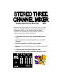
MX-5
Now here’s the simple easy to use mixer for all of you home
brew DJs out there! This mixer has two line inputs and one
microphone so that you can hook up all of your audio
sources to any transmitter or audio amplifier. Perfect for
mixing those car tapes before the big trip!
•
2 Line inputs and one mic input, all most people will ever
need!
•
Overload protection on the microphone input to “soften”
distortion
•
Requires regulated 9 to 15VDC supply or battery.
•
Line output for driving amplifiers or transmitters such as the
FM-10a
•
Long slider pots for accurate mixes every time!
•
Nice small extruded case for portability and space saving
MX-5 Page 1
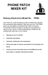
RAMSEY TRANSMITTER KITS
• FM-10a,25 FM Stereo Transmitters
• FM-1,2,4,5,6 FM Wireless Microphones
• PB-1 Telephone Transmitter
RAMSEY RECEIVER KITS
• FR-1 FM Broadcast Receiver
• AR-1 Aircraft Band Receiver
• SR-1 Short-wave Receiver
• AA-7 Active Antenna
• SC-1 Short-wave Converter
RAMSEY HOBBY KITS
• ASA-602 2x60 Watt RMS Car Amp
• ASA-604 4x60 Watt RMS Car Amp
• SF-2 Super Crossover Filter
• SP-1 Speakerphone
• MX-5,10 Stereo Mixers
• PH-14,15,16 Peak hold Meters, great
for VU meters!
• LC-1 Inductance-Capacitance Meter
RAMSEY AMATEUR RADIO KITS
• FX Series VHF and UHF Transceivers
• HR Series HF All Mode Receivers
• QRP Series HF CW Transmitters
• CW-700 Micro Memory CW Keyer
• PA Series VHF and UHF Power Amplifiers
• Packet Computer Interfaces
• QRP Power Amplifiers
RAMSEY MINI-KITS
Many other kits are available for hobby, school, Scouts and just plain FUN.
New kits are always under development. Write or call for our free Ramsey
catalog.
MX-5 STEREO MIXER INSTRUCTION MANUAL
Ramsey Electronics publication No. MMX-5 Revision 1.0
First printing: May. 1996 MRW
COPYRIGHT 1996 by Ramsey Electronics, Inc. 793 Canning Parkway, Victor, New York
14564. All rights reserved. No portion of this publication may be copied or duplicated without the
written permission of Ramsey Electronics, Inc. Printed in the United States of America.
MX-5 Page 2
Ramsey Publication No. MMX-5
Price $5.00
KIT ASSEMBLY
AND INSTRUCTION MANUAL FOR
MX-5 STEREO THREE
INPUT MIXER
TABLE OF CONTENTS
Introduction .................................... 4
How Does It Work? ........................ 5
Learn As You Build ........................ 7
Parts List ........................................ 9
Construction ................................. 10
Schematic Diagram...................... 12
Setup And Testing ....................... 16
Troubleshooting ........................... 17
Parts Value Diagram .................... 18
Parts Layout Diagram .................. 19
Using the MX-5 ............................ 21
RAMSEY ELECTRONICS, INC.
793 Canning Parkway
Victor, New York 14564
Phone (716) 924-4560
Fax (716) 924-4555
MX-5 Page 3
INTRODUCTION TO THE MX-5
Upon designing a more complex version of this kit, the MX-10, we determined
that not everyone needed all of the features in the world, so we came up with
this simple design. This is a high quality low-noise mixer capable of handling
two stereo line inputs and one mono microphone input. This gives most users
all the inputs that they will ever need for making car tapes, DJing for a wedding,
using with our stereo transmitter kits etc.
Mixers are used in all sorts of audio applications such as rock concerts, DJ
booths in bars, radio stations, recording studios and so on. If you've ever
looked at a mixer board for a concert, you would notice that they have upwards
of fifty or so channels, and seven or more controls for each channel. Each
channel has reverb, tone controls, delay, and more. Our MX-5 has only two
inputs for the line level which may include a CD player and a tape deck. The
MX-5 does not have any tonal controls for each channel, but almost all users of
this project will want a flat response anyhow. If they do not, they will run the
output of the mixer directly into an equalizer to custom-tailor their sound. For
example when a person makes a car tape, they may want to boost the bass to
get over road noise.
The MX-5 was designed for simplicity, low noise, and low cost. Its small size
makes it easy to carry around and store. Its long travel on the controls make it
easy to mix audio signals smoothly and accurately. We hope you enjoy building
and using the MX-5, we sure did at Ramsey!
MX-5 Page 4
MX-5 CIRCUIT DESCRIPTION
We will use the schematic diagram to step through the circuit and find out what
makes it “tick”. As you can see, there is only one IC in the entire circuit, but
there are four individual operational amplifiers in the one IC. U1:A and U1:B are
the main components of the mixer. They are set up in what is called a summing
amplifier.
If we were to look at the left channel only,
we can see what one of the summing
amplifiers looks like. The three inputs to this
amplifier are seen as R1, R9, and R10.
These resistors determine how much gain
each of the inputs has, in this case they are
all equal. To find the gain of each branch,
there is a simple equation:
Abranch =
Rf
RF = R4 and Rin is any one of the three branch resistors. In
this case the gain is 33K/10K = 3.3. To find the output level
R in with a given input level such as 1V P/P, multiply the input
voltage by the gain so 1*3.3 = 3.3V P/P out.
R3 and R13 determine how much line level signal is actually sent to each
branch of the summing amplifier by using slider control potentiometers. So for
the circuit up to this point to have a gain of one, the control will be set at 1/3 of
its full scale setting.
The microphone amplifier is slightly different from what you may have
expected. Not only does it have gain, but it also has two diodes in the feedback
of one of the amplifiers. First we will talk about the gain of the circuit. A typical
microphone when talked into will have an output of about 100mV, while line
level audio has a level about 1V. To get the microphone signal up to line level,
we will need an amplifier with a gain of 10. In our case we have chosen an noninverting amplifier for the job. A non-inverting amplifier has the nice feature of a
very high input impedance. This prevents loading on some high impedance
microphones which causes poor sensitivity. To find the gain of a non-inverting
amplifier, the equation is as follows:
A mic = 1 +
R 23
R 21
In our case we chose R23 at 220K ohms, so for a gain
of 10, R21 needed to be about 1/10th of that value or
24.4K. Since that is not a standard value we used a
22K ohm resistor which is close enough. (A gain of 11)
The next stage of the microphone amplifier has two diodes in the feedback
loop. What are these for? you may ask. Well they are called clipping diodes.
Diodes have a property of needing about .7 volts across them before they turn
on. On signals under .7V P/P, the gain of the second stage is determined by Ri
of 10K (R18) and Rf of 10K (R16). This gives us a gain of 1. But if our signal
MX-5 Page 5
becomes greater than .7V P/P, then the diodes D1 and D2 begin to turn on.
This brings R14 into the gain equation as well. Now you have an Rf = R14 in
parallel with R16. This brings the overall gain down to less than .1, now the
amplifier is working as an attenuator. The best part of the diodes is that they
don’t just “snap” on, they have some variance before they are on fully, so this
creates what is called “soft clipping”. This soft clipping is a close relative of
distortion, but much more tolerable. This soft clipping circuit prevents a person
from overloading amplifiers or speakers by preventing high volume levels from
exiting the mixer.
The output from the microphone amplifier is then mixed in with the line level
audio as well. Before exiting the MX-5 though, the output of U1:A and U1:B is
controlled by the master level control, R6.
The power supply for the MX-5 is simple enough, it consists of a 9-18VDC
input or battery, and a voltage divider to provide for a split supply. The spilt
supply is necessary to operate op-amps as we have done. C9 is used to filter
out most of the noises that may be present in your power supply since they
can infiltrate the audio.
MX-5 Page 6
RAMSEY “LEARN-AS-YOU-BUILD” ASSEMBLY STRATEGY
Be sure to read through all of the steps, and check the boxes as you go to be
sure you didn't miss any important steps. Although you may be in a hurry to see
results, before you switch on the power check all wiring and capacitors for
proper orientation. Also check the board for any possible solder shorts, and/or
cold solder joints. All of these mistakes could have detrimental effects on your
kit - not to mention your ego!
Kit building tips:
Use a good soldering technique - let your soldering iron tip gently heat the
traces to which you are soldering, heating both wires and pads simultaneously.
Apply the solder on the iron and the pad when the pad is hot enough to melt the
solder. The finished joint should look like a drop of water on paper, somewhat
soaked in.
The boards for the MX series of kit have components on both sides of the
board, but there is a top side that we put most of the components on. This is
the side that has little or no traces on it, but is covered with mostly copper.
When parts are installed, the part is placed flat to the board, and the leads are
bent on the backside of the board to prevent the part from falling out before
soldering (1). The part is then soldered securely to the board (2-4), and the
remaining lead length is then clipped off (5). Notice how the solder joint looks
on close up, clean and smooth with no holes or sharp points (6).
MX-5 Page 7
As with all Ramsey kits, we want to mount the parts AS LOW AS POSSIBLE to
the board. A 1/4” lead length on a resistor not mounted close to the board can
act as an inductor or an antenna, causing all sorts of problems in your circuit.
Be aware though that if there are stand up components in your circuit, they
don’t need to be squished to the board. Keep the portion of the resistor closest
to the board mounted right on the board.
For each part, our word "Install" always means these steps:
❒
❒
1. Pick the correct part value to start with.
2. Insert it into the correct PC board location, making sure the part is
mounted flush to the PC board unless otherwise noted.
❒
3. Orient it correctly, follow the PC board drawing and the written directions
for all parts - especially when there's a right way and a wrong way to solder
it in. (Diode bands, electrolytic capacitor polarity, transistor shapes, dotted
or notched ends of IC's, and so forth.)
❒
4. Solder all connections unless directed otherwise. Use enough heat and
solder flow for clean, shiny, completed connections.
Keeping this in mind, lets begin by sorting out our components and crosschecking them against the parts list to make sure we have received everything.
NOTE TO NEWCOMERS: If you are a first time kit builder you may find this
manual easier to understand than you may have expected. Each part in the kit
is checked off as you go, while a detailed description of each part is given. If
you follow each step in the manual in order, and practice good soldering and kit
building skills, the kit is next to fail-safe. If a problem does occur, the manual
will lead you through step by step in the troubleshooting guide until you find the
problem and are able to correct it.
MX-5 Page 8
RAMSEY MX-5 PARTS LIST
Semiconductors
❒
❒
❒
1 LF347 Dual operational amplifier (U1)
2 1N4148 type switching diode (D1,2)
1 1N4002 type diode (D3)
Resistors
❒
❒
❒
❒
❒
❒
❒
10 10K ohm resistors (brown-black-orange) (R1,2,9,10,11,12,15,16,17,18)
1 22K ohm resistor (red-red-orange) (R21).
2 33K ohm resistors (R4,7)
1 220K ohm resistor (red-red-yellow) (R23).
5 1K ohm resistors (brown-black-red) (R14,22,24,25,26).
2 1M ohm resistors (brown-black-green)(R19,28).
1 47K ohm resistor (yellow-violet-orange)(R27).
Capacitors
❒
❒
❒
11 10uF electrolytic capacitors (C1,2,3,4,5,6,7,10,11,12,13)
1 470uF electrolytic capacitor (C9)
1 .1uF ceramic capacitor (C8)
Controls
❒
❒
3 10K ohm slider potentiometers (R3,6,13)
1 10K ohm top mount potentiometer (R20)
Miscellaneous
❒
❒
❒
❒
❒
❒
1
1
6
1
1
1
Microphone jack (3/8”) (J8)
2.1mm Power jack (J7)
RCA style jacks (J1,2,3,4,5,6)
9 volt battery clip
9 volt battery connector
DPDT PB switch (S1)
MX-5 Page 9
ASSEMBLY OF THE MX-5
Now we are getting to the good stuff-assembling the MX-5. We will begin by
mounting first the low parts, beginning with the parts on the side of the board
without the traces. When we are finished with that side, we will begin to install
parts on the trace side of the board. This side is where all of the controls go,
and will be the side of the board facing the top of the case.
1. Install R1, a 10K ohm resistor (brown-black-orange).
2. Install R9, another 10K ohm resistor (brown-black-orange).
3. Install R2, a 10K ohm resistor (brown-black-orange).
4. Install R11, another 10K ohm resistor (brown-black-orange).
5. Install R25, a 1K ohm resistor (brown-black-red).
6. Install R4, a 33K ohm resistor (orange-orange-orange).
7. Install R10, a 10K ohm resistor (brown-black-orange).
8. Install R12 a 10K ohm resistor (brown-black-orange).
9. Install R22, a 1K ohm resistor (brown-black-red).
10. Install R16, a 10K ohm resistor (brown-black-orange).
11. Install R14, a 1K ohm resistor (brown-black-red).
12. Install D1, a 1N4148 type small signal diode (orange glass body with
black stripe on one end). Notice the direction of the diode. Make sure the
end with the line on it (cathode) is pointing in the same direction as shown
in the parts layout diagram.
13. Install D2, the other 1N4148 type small signal diode (orange glass
body with black stripe on one end). Again make sure the striped end is
pointing in the correct direction.
14. Install R24, a 1K ohm resistor (brown-black-red).
15. Install R23, a 220K ohm resistor (red-red-yellow).
16. Install R21, a 22K ohm resistor (red-red-orange).
17. Install R18, a 10K ohm resistor (brown-black-orange).
18. Install R7, a 33K ohm resistor (orange-orange-orange).
19. Install R26, a 1K ohm resistor (brown-black-red).
MX-5 Page 10
20. Now it is time to install U1, the LF347 quad opamp. Notice how on one
end of the IC there is a notch, dimple or dot indicating pin one of the IC.
You will need to align it with the notch as shown in the parts layout
diagram. Make sure all 14 pins are through the board before soldering,
and that none are bent under the IC.
21. Install R19, a 1M ohm resistor (watch out! 1,000,000 ohms!) (brownblack-green).
22. Install R28, a 1M ohm resistor (brown-black-green).
23. For R27, you will need to decide what type of microphone you wish to
use. If you plan on using a store bought microphone, you do not need to
install this resistor. If you are planning on making your own microphone as
shown later in this manual, the resistor is used to power an electorate
microphone. If in doubt, install it anyway, it will case no harm to a
microphone and it doesn’t reduce sound quality. R27 is a 47K ohm
resistor (yellow-violet-orange).
24. Install JMP1 using a scrap piece of component lead. Jumpers act as
“bridges” over other circuit paths so that signal lengths on the board are
as short as possible.
25. Install JMP2 using another scrap piece of component lead.
26. Install R15, a 10K ohm resistor (brown-black-orange).
27. Install R17, a 10K ohm resistor (brown-black-orange).
We are done installing the low profile components and are moving on to the
high profile components. Be aware of orientation of the parts when installing
them, many do not like being installed backwards and will prevent you from
having an operational kit when you are done. Before continuing though we
want to check all of your solder joints up to this point for cold solder joints or
solder bridges. If in doubt, re-heat the solder joint adding a little more new
solder.
28. Install C1, a 10uF electrolytic capacitor. Notice this is the first
capacitor of this type. You want to be sure that you pay close attention to
the polarity markings on this part. In most cases the negative (-) side is
marked on the capacitor, while the positive side (+) is marked on the parts
layout. If you fail to mount this component correctly, the part can fail as
well as prevent proper operation of your project. We will be installing many
more of these later in the project so be sure and remember this!
29. Install C4, a 10uF electrolytic capacitor. Again note polarity!
30. Install C2, another 10uF electrolytic capacitor.
MX-5 Page 11
31. Install C6, a 10uF electrolytic capacitor. (Polarity!)
32. Install C7, a 10uF electrolytic capacitor.
33. Install C3, even another 10uF electrolytic capacitor. (Need we remind
us about polarity)
34. Install C5, another 10uF electrolytic capacitor.
35. Install C8, just to throw you off, it’s a .1uF ceramic capacitor. This is
the only capacitor where orientation does not matter.
36. Install C10, a 10uF electrolytic capacitor. (Orientation!)
37. Install C12, even another 10uF electrolytic. This is getting a little dull
isn’t it? Well don’t let boredom mess you up, make sure to check polarity
of all your electrolytics up to and beyond this point.
38. Install C9, a 470uF electrolytic. This one is particularly important to
install correctly.
39. Install C11, a 10uF electrolytic capacitor.
40. Install C13, the LAST 10uF electrolytic capacitor. If we have to remind
you to check polarity again, then... Hmmm, I guess you know the
consequences!
41. Install D3, a 1N4002 type diode (black body with white stripe on one
end). This diode prevents you from inadvertently connecting external
power to the MX-5 while there is a battery installed, and trying to recharge
a battery. If this diode wasn’t there, you would very quickly have a ruined
kit.
Now we will begin installing jacks, switches and plugs. Check your work up to
this point and make sure it is up to your critical standards. Check all solder
joints for cold connections or solder bridges. Especially check between the
leads of the capacitors for stray bits of solder shorting the pins together. Also
go back and check the orientation of all the parts in your kit up to this point.
42. Install J1, an RCA type jack.
43. Install J2, another RCA jack.
44. Install J4, an RCA jack.
45. Install J6, even another RCA jack.
46. Install J8, the 3/8” microphone jack.
MX-5 Page 12
47. Install J3, another RCA jack.
48. Install J5, the last of the RCA jacks.
49. Install J7, the 2.1mm power jack.
50. Install S1, the DPDT switch. Make sure the part is flush to the board
before soldering.
51. Install the battery power clip. Make sure the red wire is installed in the
hole marked (+), and the black wire is installed in the hole marked (-).
52. Using a piece of scrap component lead, mount the battery holder to
the PC board under where the battery is to go. Note the two holes
provided for this task.
Now we are going to flip the PC board over and install the remaining controls.
Make sure and follow the steps closely from here on out. Mounting parts on
this side of the board is not conventional, but it is necessary for assembly
purposes.
53. First things first. If we were to try and install the slider pots without
what we are going to do next, you would be very frustrated when you
discover that you would have to desolder the sliders out, then put these
back in. If you look at the Control Side Layout diagram, you will see under
each of the sliders that there are jumpers, each end marked with a circle.
We will be installing these jumpers, but only soldering the end with the
circle into place before installing the sliders. The center leads of the
sliders will be sharing the larger of the two holes, so you don’t want to clog
the hole with solder yet.
54. Install the two jumpers for R6 as shown using scrap component leads.
Make sure not to solder the uncircled end yet. Make sure the jumper is
mounted flat to the board so that it doesn’t have the possibility of shorting
out the underside of the slider.
55. Install two more jumpers for R13 as shown. Use the same procedure
as in the previous step.
56. Install the last two jumpers for R3 as shown. Again make sure you do
not solder the circled ends of the slider.
57. Install R6, the 10K ohm MAIN slider pot. Notice how you will be
soldering on the same side of the board where the part is mounted. Make
sure all the slider’s pins are through the board before soldering. This may
be a little tricky, so it is best to use a fine tip soldering iron to make the job
go smoothly. Make sure and solder all four mounting lugs as well as the
two pairs of connections on each end. Then flip the board over and solder
MX-5 Page 13
the jumpers to the pins of the slider.
58. Install R13, the 10K ohm LINE2 pot the same as described in step 57.
59. Install R3, the 10K ohm LINE1 slider pot in the same way as shown in
step 57.
60. Install R20, a 10K ohm surface mounted pot, the last board mounted
part. Make sure to solder all three connections and the two solder lugs.
Wow! we are already finished putting together the kit! Lets go celebrate and
grab a soda or other drink of choice, get an eyeball break and come back in a
few minutes.
Now that you are back, we need to check over the circuit board again for any
misplaced parts. Especially check for diodes in backwards, ICs in the wrong
direction, and capacitors with their polarity backwards. Then check for cold
solder joints and possible solder bridges.
INITIAL TESTING THE MX-5
For this portion of the kit building experience you will need the following items:
Line level source such as a tape deck, signal generator or CD
player.
A destination such as an audio amp, transmitter or earphone
amplifier (Ramsey SHA-1).
A microphone if you are planning on using one.
[1] Connect the line level source to the LINE1 input jacks.
[2] Connect the destination up to the OUTPUT jacks.
[3] Connect a 9 volt battery to the battery jack, making sure the power is off. If
you do not have a battery, use a regulated power supply rated for at least
100mA.
[4] Turn the power on and verify that the destination is receiving your sound.
Vary the levels of the MAIN pot and the LINE1 pot to do this.
[5] Plug the line level source into the LINE2 input jacks.
[6] Vary MAIN and LINE2 pots to verify they work also.
[7] Plug your microphone into the microphone jack. Vary MAIN and L.MIC to
make sure it is operational as well.
MX-5 Page 14
TROUBLESHOOTING GUIDE
Well, we sincerely hope you get to skip this portion of the manual, but this is
here to help in the event of an emergency. Remember the detrimental effects
an incorrectly installed component may have on your circuit. Keep this in mind
as you troubleshoot your circuit for possible assembly errors.
PROBLEM: Nothing at all on the output of the mixer.
SOLUTION: Check your power supply voltages to make sure you have at
least 8 volts over all. Verify also that you have at least 4 volts between R15
and R17. If that is not it, check U1 for proper installation. Thereafter its a
matter of testing your source signal and that your destination is connected
properly.
PROBLEM: Left or right channel is out.
SOLUTION: This is a classic trouble shooting problem. Now is a great time to
have a little fun and teach yourself some trouble shooting skills. Make sure a
signal is present on both left and right inputs, then trace through the circuit
using an oscilloscope or DMM set on AC to find where the signal stops. You
will need to use the schematic and the board layout to assist in finding the
signal path.
PROBLEM: The microphone input screeches when I turn up the control and
no microphone is plugged in.
SOLUTION: Hmmm, the way this project worked out, by using a very high
input impedance on the microphone as well as high gain, the mic amplifier
tends to pick up on all sorts of circuit noise. Just make sure either to leave the
control turned all the way down when not in use, or just leave a microphone
plugged in.
PROBLEM: When running the output of this into the FM-10A or FM-25, I
seem to be driving the transmitters into distortion when MAIN is turned up full.
SOLUTION: Because the MX-5 has some gain, you will either need to keep
the MAIN adjustment from going all the way to full, or you can open the FM10A or FM-25, and adjust the controls for level on their inputs.
MX-5 Page 15
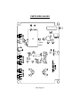
PARTS SIDE VALUES
MX-5 Page 16
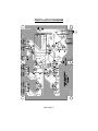
PARTS LAYOUT DIAGRAM
MX-5 Page 17
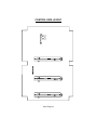
CONTROL SIDE LAYOUT
MX-5 Page 18
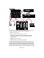
USING THE MX-5
PH-15
POWER
STC-1
MID
BASS
FM-25
HIGH
POWER
HA-3
LEFT
RIGHT
POWER
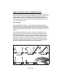
Above shows a full installation for radio broadcasting using one of the Ramsey
micropower transmitters. The parts and pieces are as follows:
MX-5, our newly built mixer
PH-15, Peak hold meter for watching audio levels
STC-1, Stereo transmitter companion. Compression, limiting, bass,
midrange, and treble controls. Active 8th order lowpass to get rid of
interfering sounds.
FM-25, the PLL stereo transmitter.
SHA-1 Headphone amplifiers for monitoring sound
To run this setup using an audio amplifier for DJing, just remove the STC-1,
and replace the FM-25 with the audio amplifier of choice. To record a car tape
or make a production, remove the STC-1 and replace the FM-25 with another
tape deck. There are many other combinations available, and it is left to one’s
imagination. Some people use this kit to mix their home audio system’s audio
with the computer’s audio. That way they can play a disk and have gory sounds
MX-5 Page 19
We sincerely hope you have enjoyed building this kit. We invite you to check
out our catalog and see all of the projects that you can put together. We have
one of the most complete line of kits available today, and many more products
to come. Give us a buzz, well send you a catalog.
Call or write:
Ramsey Electronics
793 Canning Pkwy.
Victor, NY 14564
PH# (716) 924-4560
FAX# (716) 924-4555
MX-5 Page 20
The Ramsey Kit Warranty
Please read carefully BEFORE calling or writing in about your kit. Most problems can be
solved without contacting the factory.
Notice that this is not a "fine print" warranty. We want you to understand your rights and ours too!
All Ramsey kits will work if assembled properly. The very fact that your kit includes this new manual
is your assurance that a team of knowledgeable people have field-tested several "copies" of this kit
straight from the Ramsey Inventory. If you need help, please read through your manual carefully.
All information required to properly build and test your kit is contained within the pages!
1. DEFECTIVE PARTS: It's always easy to blame a part for a problem in your kit, Before you
conclude that a part may be bad, thoroughly check your work. Today's semiconductors and passive
components have reached incredibly high reliability levels, and it’s sad to say that our human
construction skills have not! But on rare occasions a sour component can slip through. All our kit
parts carry the Ramsey Electronics Warranty that they are free from defects for a full ninety (90)
days from the date of purchase. Defective parts will be replaced promptly at our expense. If you
suspect any part to be defective, please mail it to our factory for testing and replacement. Please
send only the defective part(s), not the entire kit. The part(s) MUST be returned to us in suitable
condition for testing. Please be aware that testing can usually determine if the part was truly
defective or damaged by assembly or usage. Don't be afraid of telling us that you 'blew-it', we're all
human and in most cases, replacement parts are very reasonably priced.
2. MISSING PARTS: Before assuming a part value is incorrect, check the parts listing carefully to
see if it is a critical value such as a specific coil or IC, or whether a RANGE of values is suitable
(such as "100 to 500 uF"). Often times, common sense will solve a mysterious missing part
problem. If you're missing five 10K ohm resistors and received five extra 1K resistors, you can
pretty much be assured that the '1K ohm' resistors are actually the 'missing' 10 K parts ("Hum-m-m,
I guess the 'red' band really does look orange!") Ramsey Electronics project kits are packed with
pride in the USA. If you believe we packed an incorrect part or omitted a part clearly indicated in
your assembly manual as supplied with the basic kit by Ramsey, please write or call us with
information on the part you need and proof of kit purchase.
3. FACTORY REPAIR OF ASSEMBLED KITS:
To qualify for Ramsey Electronics factory repair, kits MUST:
1. NOT be assembled with acid core solder or flux.
2. NOT be modified in any manner.
3. BE returned in fully-assembled form, not partially assembled.
4. BE accompanied by the proper repair fee. No repair will be undertaken until we have received
the MINIMUM repair fee (1/2 hour labor) of $18.00, or authorization to charge it to your
credit card account.
5. INCLUDE a description of the problem and legible return address. DO NOT send a separate
letter; include all correspondence with the unit. Please do not include your own hardware
such as non-Ramsey cabinets, knobs, cables, external battery packs and the like. Ramsey
Electronics, Inc., reserves the right to refuse repair on ANY item in which we find excessive
problems or damage due to construction methods. To assist customers in such situations,
Ramsey Electronics, Inc., reserves the right to solve their needs on a case-by-case basis.
The repair is $36.00 per hour, regardless of the cost of the kit. Please understand that our
technicians are not volunteers and that set-up, testing, diagnosis, repair and repacking and
paperwork can take nearly an hour of paid employee time on even a simple kit. Of course, if we find
that a part was defective in manufacture, there will be no charge to repair your kit (But please
realize that our technicians know the difference between a defective part and parts burned out or
damaged through improper use or assembly).
4. REFUNDS: You are given ten (10) days to examine our products. If you are not satisfied, you
may return your unassembled kit with all the parts and instructions and proof of purchase to the
factory for a full refund. The return package should be packed securely. Insurance is
recommended. Please do not cause needless delays, read all information carefully.
MX-5 Page 21
MX-5 STEREO THREE CHANNEL MIXER KIT
Quick Reference Page Guide
Introduction.......................................... 4
How Does It Work? .............................. 5
Learn As You Build .............................. 7
Parts List ............................................. 9
Construction ...................................... 10
Schematic Diagram ........................... 12
Setup And Testing ............................. 16
Troubleshooting ................................. 17
Parts Value Diagram.......................... 18
Parts Layout Diagram ........................ 19
Using the MX-5 .................................. 21
REQUIRED TOOLS
• Soldering Iron Ramsey #RTS06, (Radio Shack #RS64-2072)
• Thin Rosin Core Solder Ramsey #RTS12, (RS64-025)
• Needle Nose Pliers Ramsey #RTS05, (RS64-1844)
• Small Diagonal Cutters Ramsey #RTS04, (RS64-1845)
<OR> Complete Soldering Tool Set (RS64-2801)
ADDITIONAL SUGGESTED ITEMS
Soldering Iron Holder/Cleaner (RS64-2078)
Holder for PC Board/Parts Ramsey #RTS13, (RS64-2094)
•
•
Price: $10.00
Ramsey Publication No. MMX-5
Assembly and Instruction manual for:
RAMSEY MODEL NO. MX-5
RAMSEY ELECTRONICS, INC.
793 Canning Parkway
Victor, New York 14564
Phone (716) 924-4560
Fax (716) 924-4555
MX-5 Page 22
TOTAL SOLDER POINTS
170
ESTIMATED ASSEMBLY
TIME
Beginner .............. 7 hrs
Intermediate......... 5 hrs
Advanced ............. 4 hrs
Printed on recycled