1
User’s Manual
VSC 150
Scan Converter
Extron Electronics, USA
1230 South Lewis Street, Anaheim, CA 92805
800.633.9876 714.491.1500 FAX 714.491.1517
USA
Extron Electronics, Europe
Beeldschermweg 6C, 3821 AH Amersfoort
+31.33.453.4040 FAX +31.33.453.4050
The Netherlands
Extron Electronics, Asia
135 Joo Seng Rd. #04-01, PM Industrial Bldg.
+65.383.4400 FAX +65.383.4664
Singapore 368363
© 2001 Extron Electronics. All rights reserved.
Extron Electronics Information
ExtronWEB™: www.extron.com
ExtronFAX™: 714.491.0192
24-hour access—worldwide!
68-469-01
Printed in the USA
Precautions
Safety Instructions • English
This symbol is intended to alert the user of important
operating and maintenance (servicing) instructions
in the literature provided with the equipment.
This symbol is intended to alert the user of the
presence of uninsulated dangerous voltage within
the product's enclosure that may present a risk of
electric shock.
Caution
Read Instructions • Read and understand all safety and operating
instructions before using the equipment.
Retain Instructions • The safety instructions should be kept for future
reference.
Follow Warnings • Follow all warnings and instructions marked on the
equipment or in the user information.
Avoid Attachments • Do not use tools or attachments that are not
recommended by the equipment manufacturer because they may be
hazardous.
Consignes de Sécurité • Français
Ce symbole sert à avertir l’utilisateur que la
documentation fournie avec le matériel contient des
instructions importantes concernant l’exploitation
et la maintenance (réparation).
Ce symbole sert à avertir l’utilisateur de la présence
dans le boîtier de l’appareil de tensions dangereuses
non isolées posant des risques d’électrocution.
Attention
Lire les instructions• Prendre connaissance de toutes les consignes de
sécurité et d’exploitation avant d’utiliser le matériel.
Conserver les instructions• Ranger les consignes de sécurité afin de
pouvoir les consulter à l’avenir.
Respecter les avertissements • Observer tous les avertissements et
consignes marqués sur le matériel ou présentés dans la documentation
utilisateur.
Eviter les pièces de fixation • Ne pas utiliser de pièces de fixation ni
d’outils non recommandés par le fabricant du matériel car cela
risquerait de poser certains dangers.
Sicherheitsanleitungen • Deutsch
Dieses Symbol soll dem Benutzer in der im
Lieferumfang enthaltenen Dokumentation
besonders wichtige Hinweise zur Bedienung und
Wartung (Instandhaltung) geben.
Dieses Symbol soll den Benutzer darauf aufmerksam
machen, daß im Inneren des Gehäuses dieses
Produktes gefährliche Spannungen, die nicht isoliert
sind und die einen elektrischen Schock verursachen
können, herrschen.
Achtung
Lesen der Anleitungen • Bevor Sie das Gerät zum ersten Mal verwenden,
sollten Sie alle Sicherheits-und Bedienungsanleitungen genau
durchlesen und verstehen.
Aufbewahren der Anleitungen • Die Hinweise zur elektrischen Sicherheit
des Produktes sollten Sie aufbewahren, damit Sie im Bedarfsfall darauf
zurückgreifen können.
Befolgen der Warnhinweise • Befolgen Sie alle Warnhinweise und
Anleitungen auf dem Gerät oder in der Benutzerdokumentation.
Keine Zusatzgeräte • Verwenden Sie keine Werkzeuge oder Zusatzgeräte,
die nicht ausdrücklich vom Hersteller empfohlen wurden, da diese eine
Gefahrenquelle darstellen können.
Instrucciones de seguridad • Español
Este símbolo se utiliza para advertir al usuario sobre
instrucciones importantes de operación y
mantenimiento (o cambio de partes) que se desean
destacar en el contenido de la documentación
suministrada con los equipos.
Este símbolo se utiliza para advertir al usuario sobre
la presencia de elementos con voltaje peligroso sin
protección aislante, que puedan encontrarse dentro
de la caja o alojamiento del producto, y que puedan
representar riesgo de electrocución.
Precaucion
Leer las instrucciones • Leer y analizar todas las instrucciones de
operación y seguridad, antes de usar el equipo.
Conservar las instrucciones • Conservar las instrucciones de seguridad
para futura consulta.
Obedecer las advertencias • Todas las advertencias e instrucciones
marcadas en el equipo o en la documentación del usuario, deben ser
obedecidas.
Evitar el uso de accesorios • No usar herramientas o accesorios que no
sean especificamente recomendados por el fabricante, ya que podrian
implicar riesgos.
FCC Class A Notice
Warning
Power sources • This equipment should be operated only from the power source
indicated on the product. This equipment is intended to be used with a main
power system with a grounded (neutral) conductor. The third (grounding) pin is
a safety feature, do not attempt to bypass or disable it.
Power disconnection • To remove power from the equipment safely, remove all
power cords from the rear of the equipment, or the desktop power module (if
detachable), or from the power source receptacle (wall plug).
Power cord protection • Power cords should be routed so that they are not likely to
be stepped on or pinched by items placed upon or against them.
Servicing • Refer all servicing to qualified service personnel. There are no userserviceable parts inside. To prevent the risk of shock, do not attempt to service
this equipment yourself because opening or removing covers may expose you to
dangerous voltage or other hazards.
Slots and openings • If the equipment has slots or holes in the enclosure, these are
provided to prevent overheating of sensitive components inside. These openings
must never be blocked by other objects.
Lithium battery • There is a danger of explosion if battery is incorrectly replaced.
Replace it only with the same or equivalent type recommended by the
manufacturer. Dispose of used batteries according to the manufacturer's
instructions.
Avertissement
Alimentations• Ne faire fonctionner ce matériel qu’avec la source d’alimentation
indiquée sur l’appareil. Ce matériel doit être utilisé avec une alimentation
principale comportant un fil de terre (neutre). Le troisième contact (de mise à la
terre) constitue un dispositif de sécurité : n’essayez pas de la contourner ni de la
désactiver.
Déconnexion de l’alimentation• Pour mettre le matériel hors tension sans danger,
déconnectez tous les cordons d’alimentation de l’arrière de l’appareil ou du
module d’alimentation de bureau (s’il est amovible) ou encore de la prise secteur.
Protection du cordon d’alimentation • Acheminer les cordons d’alimentation de
manière à ce que personne ne risque de marcher dessus et à ce qu’ils ne soient
pas écrasés ou pincés par des objets.
Réparation-maintenance • Faire exécuter toutes les interventions de réparationmaintenance par un technicien qualifié. Aucun des éléments internes ne peut être
réparé par l’utilisateur. Afin d’éviter tout danger d’électrocution, l’utilisateur ne
doit pas essayer de procéder lui-même à ces opérations car l’ouverture ou le
retrait des couvercles risquent de l’exposer à de hautes tensions et autres dangers.
Fentes et orifices • Si le boîtier de l’appareil comporte des fentes ou des orifices,
ceux-ci servent à empêcher les composants internes sensibles de surchauffer. Ces
ouvertures ne doivent jamais être bloquées par des objets.
Lithium Batterie • Il a danger d'explosion s'll y a remplacment incorrect de la
batterie. Remplacer uniquement avec une batterie du meme type ou d'un ype
equivalent recommande par le constructeur. Mettre au reut les batteries usagees
conformement aux instructions du fabricant.
Vorsicht
Stromquellen • Dieses Gerät sollte nur über die auf dem Produkt angegebene
Stromquelle betrieben werden. Dieses Gerät wurde für eine Verwendung mit
einer Hauptstromleitung mit einem geerdeten (neutralen) Leiter konzipiert. Der
dritte Kontakt ist für einen Erdanschluß, und stellt eine Sicherheitsfunktion dar.
Diese sollte nicht umgangen oder außer Betrieb gesetzt werden.
Stromunterbrechung • Um das Gerät auf sichere Weise vom Netz zu trennen,
sollten Sie alle Netzkabel aus der Rückseite des Gerätes, aus der externen
Stomversorgung (falls dies möglich ist) oder aus der Wandsteckdose ziehen.
Schutz des Netzkabels • Netzkabel sollten stets so verlegt werden, daß sie nicht
im Weg liegen und niemand darauf treten kann oder Objekte darauf- oder
unmittelbar dagegengestellt werden können.
Wartung • Alle Wartungsmaßnahmen sollten nur von qualifiziertem
Servicepersonal durchgeführt werden. Die internen Komponenten des Gerätes
sind wartungsfrei. Zur Vermeidung eines elektrischen Schocks versuchen Sie in
keinem Fall, dieses Gerät selbst öffnen, da beim Entfernen der Abdeckungen die
Gefahr eines elektrischen Schlags und/oder andere Gefahren bestehen.
Schlitze und Öffnungen • Wenn das Gerät Schlitze oder Löcher im Gehäuse
aufweist, dienen diese zur Vermeidung einer Überhitzung der empfindlichen
Teile im Inneren. Diese Öffnungen dürfen niemals von anderen Objekten
blockiert werden.
Litium-Batterie • Explosionsgefahr, falls die Batterie nicht richtig ersetzt wird.
Ersetzen Sie verbrauchte Batterien nur durch den gleichen oder einen
vergleichbaren Batterietyp, der auch vom Hersteller empfohlen wird. Entsorgen
Sie verbrauchte Batterien bitte gemäß den Herstelleranweisungen.
Advertencia
Alimentación eléctrica • Este equipo debe conectarse únicamente a la fuente/tipo
de alimentación eléctrica indicada en el mismo. La alimentación eléctrica de este
equipo debe provenir de un sistema de distribución general con conductor
neutro a tierra. La tercera pata (puesta a tierra) es una medida de seguridad, no
puentearia ni eliminaria.
Desconexión de alimentación eléctrica • Para desconectar con seguridad la
acometida de alimentación eléctrica al equipo, desenchufar todos los cables de
alimentación en el panel trasero del equipo, o desenchufar el módulo de
alimentación (si fuera independiente), o desenchufar el cable del receptáculo de
la pared.
Protección del cables de alimentación • Los cables de alimentación eléctrica se
deben instalar en lugares donde no sean pisados ni apretados por objetos que se
puedan apoyar sobre ellos.
Reparaciones/mantenimiento • Solicitar siempre los servicios técnicos de personal
calificado. En el interior no hay partes a las que el usuario deba acceder. Para
evitar riesgo de electrocución, no intentar personalmente la reparación/
mantenimiento de este equipo, ya que al abrir o extraer las tapas puede quedar
expuesto a voltajes peligrosos u otros riesgos.
Ranuras y aberturas • Si el equipo posee ranuras o orificios en su caja/alojamiento,
es para evitar el sobrecalientamiento de componentes internos sensibles. Estas
aberturas nunca se deben obstruir con otros objetos.
Batería de litio • Existe riesgo de explosión si esta batería se coloca en la posición
incorrecta. Cambiar esta batería únicamente con el mismo tipo (o su equivalente)
recomendado por el fabricante. Desachar las baterías usadas siguiendo las
instrucciones del fabricante.
Note: This equipment has been tested and found to comply with the limits for a
Class A digital device, pursuant to part 15 of the FCC Rules. These limits are designed
to provide reasonable protection against harmful interference when the equipment is
operated in a commercial environment. This equipment generates, uses and can
radiate radio frequency energy and, if not installed and used in accordance with the
instruction manual, may cause harmful interference to radio communications.
Operation of this equipment in a residential area is likely to cause harmful
interference, in which case the user will be required to correct the interference at his
own expense.
Note: This unit was tested with shielded cables on the peripheral devices. Shielded
cables must be used with the unit to ensure compliance.
Extron’s Warranty
Extron Electronics warrants this product against defects in materials and
workmanship for a period of two years from the date of purchase. In the event of
malfunction during the warranty period attributable directly to faulty workmanship
and/or materials, Extron Electronics will, at its option, repair or replace said products
or components, to whatever extent it shall deem necessary to restore said product to
proper operating condition, provided that it is returned within the warranty period,
with proof of purchase and description of malfunction to:
USA, Canada,
South America, and
Central America:
Extron Electronics
1230 South Lewis Street
Anaheim, CA 92805, USA
Europe, Africa, and
the Middle East:
Asia:
Extron Electronics, Europe
Beeldschermweg 6C
3821 AH Amersfoort
The Netherlands
Extron Electronics, Asia
135 Joo Seng Road, #04-01
PM Industrial Bldg.
Singapore 368363
This Limited Warranty does not apply if the fault has been caused by misuse,
improper handling care, electrical or mechanical abuse, abnormal operating conditions
or non-Extron authorized modification to the product.
If it has been determined that the product is defective, please call Extron and ask for an
Applications Engineer at (714) 491-1500 (USA), 31.33.453.4040 (Europe), or 65.383.4400
(Asia) to receive an RA# (Return Authorization number). This will begin the repair
process as quickly as possible.
Units must be returned insured, with shipping charges prepaid. If not insured, you
assume the risk of loss or damage during shipment. Returned units must include the
serial number and a description of the problem, as well as the name of the person to
contact in case there are any questions.
Extron Electronics makes no further warranties either expressed or implied with
respect to the product and its quality, performance, merchantability, or fitness for any
particular use. In no event will Extron Electronics be liable for direct, indirect, or
consequential damages resulting from any defect in this product even if Extron
Electronics has been advised of such damage.
Please note that laws vary from state to state and country to country, and that some
provisions of this warranty may not apply to you.
Table of Contents
Chapter 1 • Introduction .......................................................... 1-1
About this Manual ................................................................ 1-2
About the VSC 150 ................................................................ 1-2
Features ...................................................................................... 1-2
Chapter 2 • Installation and Operation ......................... 2-1
Installation Overview .......................................................... 2-2
Mounting the VSC 150 ........................................................ 2-2
Tabletop/desktop placement ................................................ 2-2
Rack mounting ....................................................................... 2-3
Front Panel Features ............................................................ 2-4
Rear Panel Features .............................................................. 2-7
Cabling ........................................................................................ 2-9
Mac-HV/VGA cable connector pin assignments ................. 2-12
Optimizing the Image ....................................................... 2-12
Setting Up Genlock and
Vertical Interval Switching ............................................. 2-13
Vertical interval switching setup ........................................ 2-13
Genlock setup ...................................................................... 2-14
Oscilloscope displays ............................................................ 2-16
Troubleshooting ................................................................... 2-17
If the image does not appear .......................................... 2-17
If the image does not display correctly ............................ 2-18
If the scan converter does not respond to controls ......... 2-19
Chapter 3 • Remote Control .................................................. 3-1
RS-232 RemoteControl ........................................................ 3-2
Host-to-VSC communications ................................................ 3-2
VSC-initiated messages ...................................................... 3-2
VSC error responses ........................................................... 3-3
Time-out ............................................................................ 3-3
Using the command/response table ..................................... 3-3
Command/response table ..................................................... 3-4
Control software for Windows ............................................. 3-6
Installing the software ....................................................... 3-6
Using the software ............................................................ 3-6
IR Remote Control ................................................................. 3-7
Using the memory feature .................................................... 3-8
(Continued)
VSC 150 • Table of Contents
i
Table of Contents, cont’d
Appendix • Specifications, Accessories and
Part Numbers ................................................................................... A-1
VSC 150
Specifications ......................................................................... A-2
Included Parts ......................................................................... A-4
Accessories ............................................................................... A-4
1
Chapter One
Introduction
About this Manual
About the VSC 150
Features
68-469-01 D
Printed in the USA
01 01
ii
VSC 150 • Table of Contents
Introduction, cont’d
Introduction
About this Manual
This manual contains information about Extron’s VSC 150
scan converter and how to install, operate and configure it.
It also explains how to operate the IR 601 remote control.
About the VSC 150
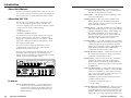
Extron’s VSC 150 is a high resolution computer-to-video
scan converter with all digital controls. The VSC 150
converts a computer video signal into two display outputs
– composite video and one of the following:
• S-video,
• component video, or
• RGB video (RGBHV or RGBS)
for simultaneous scan-converted output on two separate
devices. This allows the video from a computer to be
displayed on a television monitor or recorded on a DVD,
VCR, video editing bay or other recording device. All of
the outputs are NTSC/PAL.
This scan converter accepts one Macintosh or VGA
computer input of a resolution up to 1152 x 900 and
provides a local monitor loop-out.
The VSC 150 is 1U high and one half rack wide. It is rack
mountable, and has an internal, autoswitching power
supply. It can be controlled via front panel buttons, RS-232
remote control, and infrared (IR) control.
FILTERING
HORZ
I
II
FREEZE
VERT
CENTERING/PAN SIZE
I ENCODER
I
II
II
III
III
GENLOCK
MIN/ BURST HORZ
MAX LOCK PHASE
SUB
PHASE
SIZE
VSC 150
SCAN CONVERTER
VIDEO
0.3A
MAC
50/60 Hz
VGA
I
N
P
U
T
S
PAL OUT
75 OHM
100-240 V
O
U
T
P S-VIDEO
U
T
S
R/R-Y
G/Y
B/B-Y
H
V
S
GENLOCK
IN
S-VIDEO
RGB
R-Y/B-Y/Y
OUT RS-232
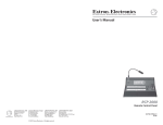
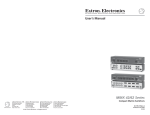
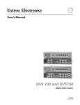
VSC 150 front and rear panels
Features
Picture sizing/zoom controls — Separate digital rotary
controls on the VSC 150 allow horizontal and/or
vertical picture resizing to fit the display device or
zoom in or out. These settings are stored in userdefined memories.
1-2
VSC 150 • Introduction
Picture centering and panning — Center the picture
horizontally and vertically or pan across the picture
with these front panel rotary controls.
Freeze mode — This feature provides a still image of the
scan-converted picture.
Filtering controls — Horizontal, vertical and encoder
filtering levels are user-selectable from the front
panel or remote controls for control of picture detail
clarity and flicker reduction.
Memory presets — The VSC 150 offers 30 factory-defined
and 30 user-defined presets for size, zoom, panning,
centering and filtering settings. These settings can
be recalled automatically in association with a
particular input signal scan rate. Three additional
user-defined presets can be stored and retrieved
manually via IR or RS-232 remote control.
Executive mode — To prevent unauthorized or accidental
adjustments to the VSC 150’s settings via front panel
controls, Executive mode locks all the front panel
features except centering controls. Adjustments can
still be made via RS-232 control and IR remote
control when executive mode is active.
Infrared (IR) remote control — All the functions that can
be controlled via front panel controls can be also be
controlled via an IR remote control.
RS-232 control — The VSC 150 can also be controlled via
computer or another control device through an
RS-232 connection and Extron’s Simple Instruction
Set™ (SIS™) or the Extron graphical control program
for Windows®.
Choice of output formats — NTSC/PAL composite video
output is continuously available on a rear panel BNC
connector. In addition, one other output can also be
active. Choose from the following formats via a rear
panel switch and cable connections:
• RGBHV (separate horizontal and vertical sync),
• RGBS (composite sync),
• Y, R-Y, B-Y (component video), or
• S-video output.
Genlock (burst lock) synchronization — The VSC 150 can
be connected to a genlock (burst lock/black burst)
sync signal generator via rear panel connectors, and
the phase differences between the genlock sync and
output video sync can be adjusted separately for the
VSC 150 • Introduction
1-3
Introduction, cont’d
horizontal and color subcarrier signals. Genlocking
provides for seamless vertical interval switching
between the scan-converted signal and signals from
other video sources.
VGA or Macintosh input and local monitor output — The
15-pin HD and 15-pin D connectors allow easy
connection to a PC or Mac local monitor. The
included male Mac-VGA cable connects the VSC 150
to the computer without need for additional
adapters.
Rack mountability — The VSC 150 can be rack mounted
on one side of an optional 1U rack shelf (Extron part
#60-190-01).
VSC 150
2
Chapter Two
Installation and Operation
Installation Overview
Mounting the VSC 150
Front Panel Features
Rear Panel Features
Cabling
Optimizing the Image
Setting Up Genlock and Vertical Interval Switching
Troubleshooting
1-4
VSC 150 • Introduction
Installation and
Operation,
cont’d
Installation
and
Operation
Installation Overview
To install and set up the VSC 150, follow these basic steps:
1
Turn all of the equipment off. Make sure that the
source computer, the VSC 150, the output devices
(projector, monitors), genlock device (black burst
generator), and remote control devices are turned off
and disconnected from the power source.
2
Mount the scan converter. See “Mounting the
VSC 150” in this chapter.
3
Set the rear panel toggle and DIP switches. See “Rear
Panel Features” in this chapter for details.
4
Attach the cables. See “Cabling” and “Rear Panel
Features” in this chapter.
5
Connect power cords and turn on all the equipment.
6
The image should now appear. If not, ensure that all
devices are plugged in and receiving power. Check
the cabling and rear panel switches, and make
adjustments as needed. See “Troubleshooting” in
this chapter if needed.
7
Using an oscilloscope, set up and adjust the genlock
signal. See “Setting Up Genlock and Vertical Interval
Switching” in this manual.
8
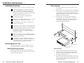
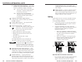
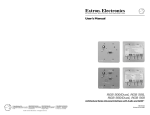
Rack mounting
1.
If feet were installed on the bottom of the VSC 150,
remove them.
2.
Place the VSC 150 on one half of the 1U (one unit high,
one unit wide) rack shelf (part #60-190-01). Align the
front of the VSC 150 with the front of the shelf, and
align the threaded holes on the bottom of the VSC 150
with the holes in the rack shelf.
3.
Attach the VSC 150 to the rack shelf with the two
provided 4-40 x 1/8” machine screws. Insert the
screws from the underside of the shelf, and securely
fasten them into diagonally-opposite corners as
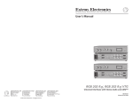
shown in the illustration below.
False front panel
uses 2 front holes
Adjust filtering and other settings from the front
panel buttons, or RS-232 or IR remote controller. See
“Front Panel Features” in this chapter for details. See
“Troubleshooting” in this chapter if needed.
HO
FR
EE
ZE
RZ
I
FIL
TE
RING
VE
RT
II
I EN
II
III
CO
DE
R
CE
NT
ER
ING/
I
II
PA
N SIZ
E
III
Mounting the VSC 150
SIZ
E
GE
NL
OC
MI
K
MAN/ BU
X
LORST
CK HO
PH RZ
AS
E SU
PH B
AS
SC
Select tabletop placement or rack mounting. Follow the
appropriate installation instructions on these two pages.
Tabletop/desktop placement
For tabletop or desktop placement only, install the selfadhesive rubber feet/pads (provided) onto the four corners
of the bottom of the enclosure.
2-2
VSC 150 • Installation and Operation
AN
VS
CO
C
NV
15
E
(2) 4-40 x 1/8" Screws
0
ER
TE
R
Use 2 mounting holes on
opposite corners
Rack mounting
4.
Attach the false front panel (provided with the rack
shelf) to the unoccupied side of the rack (as shown
above), or install a second half-rack-width device in
that side by repeating steps 1 – 3.
5.
Attach the rack shelf to the rack using four 10-32 x ¾”
bolts (provided). Insert the bolts through #10 beveled
washers, then through the holes in the rack ears and
rack, as shown above.
VSC 150 • Installation and Operation
2-3
Installation and Operation, cont’d
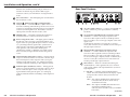
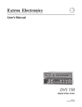
Front Panel Features
FILTERING
HORZ
I
VERT
II
FREEZE
CENTERING/PAN SIZE
I ENCODER
I
II
II
III
III
2 seconds to activate Executive mode. Executive mode
prevents unauthorized or accidental adjustments to the
VSC 150’s settings via front panel controls by locking all
the front panel features except centering controls.
Adjustments can still be made via RS-232 control or
IR remote control when Executive mode is active. To
release Executive mode and allow access to all front panel
functions, press the Freeze and Size buttons simultaneously
again for 2 seconds.
GENLOCK
MIN/ BURST HORZ
MAX LOCK PHASE
SUB
PHASE
SIZE
VSC 150
SCAN CONVERTER
1
2
3
4
5
6
7
8
9
10
11 12
13
14 15 16
17
Adjustments to front panel features and controls do not
affect the local monitor.
1
2
3
Power/signal lock LED — If this indicator...
• Lights amber yellow without blinking, the VSC 150 is
receiving power, but no input signal is present.
• Blinks green, the unit is receiving power, but the input
signal has a resolution that is too low or too high.
• Blinks green when the signal is within range, the
VSC 150 is receiving commands from the IR 601
remote control.
• Lights green without blinking, the input signal is within
range, and the VSC 150 has locked to that particular
resolution.
IR receiver window — The VSC 150 receives infrared
signals from the IR remote controller through this window.
The IR remote controller must be in the direct line of sight
of this window when it is in use.
Freeze control — Press this button to display (or record) a
still image of the scan-converted picture from both display
outputs. (See “Rear Panel Features” and “Cabling” for
information on these outputs.) The freeze LED indicator
lights while this control is active. To turn this feature off,
press the Freeze button again. Freeze affects both outputs
simultaneously. No matter what the format is (RGB,
component, S-video or composite video), the image will be
“frozen”. The image on the local monitor will not be
“frozen”.
All controls except Freeze will be locked on both the front
panel and the IR remote control while Freeze mode is
active. Press the Freeze button again to turn off Freeze
mode and unlock the other controls.
3 + 11 Executive mode (Freeze + Size) — Press the
Freeze control together with the Size button for
2-4
VSC 150 • Installation and Operation
4
Freeze indicator LED — This LED lights green to indicate
that the freeze feature is active.
5
Horizontal (Horz) filtering control — Press this button to
choose between the two levels of horizontal filtering to
yield the best picture detail.
6
Horizontal filtering LEDs — These LEDs light yellow to
indicate the selected horizontal filtering level.
7
Vertical (Vert) filtering control — Press this button to
choose one of the three levels of vertical filtering. Select
the setting that yields the least amount of flicker.
8
Vertical filtering LEDs — These LEDs light yellow to
indicate the selected level of vertical filtering.
9
Encoder filtering control — Press this button to choose
one of the three levels of encoder filters. Select the setting
that gives the best picture detail.
10
Encoder filtering LEDs — These LEDs light yellow to
indicate the selected level of encoder filtering.
11
Size control — Press this button to activate the size
feature. When Size is active, the picture can be resized
vertically and/or horizontally by rotating the vertical and
horizontal Centering/Pan/Size rotary controls (13).
Observe the picture on screen as you adjust the controls.
To zoom in, adjust the size so the picture exceeds the
screen’s limits. The Min/Max LED (14) lights red when the
minimum or maximum limit of a control has been reached.
The size feature affects both display outputs
simultaneously. The image is resized no matter what
format is selected (RGB, component, S-video or composite
video). The local monitor loop-out is not affected.
The size function remains active for 8 seconds after the
rotary controls become inactive. The rotary controls then
(Continued on the next page)
VSC 150 • Installation and Operation
2-5
Installation and Operation, cont’d
See Freeze control (3) for information on using Executive
mode.
12
13
Size control LED — This LED lights green to indicate that
the size feature is active.
Vertical ( ) and horizontal ( ) Centering/Pan/Size
rotary controls — Turn these knobs to adjust vertical or
horizontal centering (when the image size does not exceed
screen size) and panning (when the image size exceeds the
screen size) in the regular mode. Rotate these controls to
adjust picture size when the Size mode is active.
14
Min/Max LED — This lights red when the minimum or
maximum limit of a control (13) has been reached.
15
Burst Lock (genlock) LED — This lights green to indicate
that the VSC 150 is receiving a genlock (black burst) sync
signal via the rear panel genlock input connector. Genlock
is a sync timing reference signal used to synchronize an
entire system’s components. If this LED does not light
when genlock is active, then either further phase
adjustment is needed, or a different, more stable or timebase-corrected sync signal must be used for the genlock
source.
16
17
Horizontal phase (Horz Phase) control — During genlock
setup use a small screwdriver to rotate this control to align
the horizontal phase of the composite video sync signal
with that of the genlock signal. See “Setting Up Genlock
and Vertical Interval Switching” in this chapter for details.
Subcarrier phase (Sub Phase) control — During genlock
setup use a small screwdriver to rotate this control to align
the color subcarrier phase of the composite video sync
signal with that of the genlock signal. See “Setting Up
Genlock and Vertical Interval Switching” in this chapter for
details.
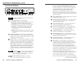
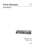
Rear Panel Features
100-240 V
VIDEO
0.3A
MAC
50/60 Hz
I
N
P
U
T
S
PAL OUT
75 OHM
default to the standard centering and pan functions. To
turn the size feature off, press the Size button again.
O
U
T
P S-VIDEO
U
T
S
2
3
5
6
B/B-Y
H
V
S
GENLOCK
IN
RGB
R-Y/B-Y/Y
4
G/Y
S-VIDEO
VGA
1
R/R-Y
7
8
OUT RS-232
9
10
1
AC power input connector — Connect a standard IEC AC
power cord here for power input (100VAC to 240VAC,
50/60 Hz).
2
VGA computer input/Macintosh local monitor output
connector — Connect a VGA-type computer to the
VSC 150 via this 15-pin D connector (and the provided
Mac-VGA cable) to use a VGA-type computer as the video
signal source.
If a Macintosh, instead of a VGA-type PC, is used as a
source, this connector serves as the Mac local monitor passthrough output connector.
3
Macintosh (Mac) input/VGA local monitor output
connector — Connect a Macintosh computer to the
VSC 150 via this 15-pin HD connector (and the provided
Mac-VGA cable) to use a Mac as the video signal source.
If a VGA/SVGA-type computer, instead of a Macintosh, is
used as a source, this connector serves as the VGA local
monitor pass-through output connector.
4
DIP switches — These two switches select the signal
standard (NTSC or PAL) applied to the scan converted
video output, and the video input termination (75 ohm or
high impedance).
1 — PAL Out — Select the output standard with this
switch. This switch affects both of the display outputs
(composite video and one other), but not the local
monitor.
ON — The output is in PAL (Phase Alternate Line)
format (625 lines/frame at 50 Hz vertical,
15.625 kHz horizontal).
OFF — The output is in NTSC (National Television
Standards Committee) format
(525 lines/frame at 60 Hz vertical, 15.734 kHz
horizontal).
(Continued)
2-6
VSC 150 • Installation and Operation
VSC 150 • Installation and Operation
2-7
Installation and Operation, cont’d
2 — 75 Ohm (video input termination) — This switch
provides a way to prevent blooming when no local
monitor or termination adapter is connected.
switching between sources. See “Cabling” and
“Setting Up Genlock and Vertical Interval Switching”
in this chapter.
ON — The VSC 150 provides 75 ohm video input
termination. Select this setting when a
local monitor is not used.
OFF — The VSC 150 provides high Z (high
impedance) video input termination. Use
this setting when the system includes a
local monitor.
10
RS-232 connector — Connect a computer or RS-232
control module to this 9-pin D connector to allow
remote control using the Simple Instruction Set or the
Extron graphical control program for Windows. See
chapter 3, “Remote Control” for details.
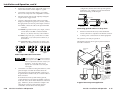
Cabling
5
Composite video (Video) output connector —
Composite video output is continuously available on
this BNC connector.
Attach cables to the scan converter as detailed in the steps
below. A diagram on page 2-11 shows how the system
looks when cabling is finished.
6
S-video output connector — This 4-pin mini-DIN
connector is for S-video output.
1.
Connect the local monitor via its video input cable to
the corresponding (Mac or VGA) “input” connector
on the VSC 150’s rear panel.
7
Output selection switch — In addition to the
composite video output, one other output can
also be active. Choose from the following
formats via the output selection switch:
2.
Using the included Mac-VGA cable, connect the
computer’s video output to the other input connector.
See the diagram below and the pin assignment
information on page 2-12.
• S-video output (select S-video),
•
If the source computer is a Macintosh, plug the
VGA (15-pin HD) end into the VSC 150, and plug
the other (15-pin D) end into the computer’s
output connector.
•
If the source computer is a VGA-type PC, plug
the Mac (15-pin D) end into the VSC 150, and
plug the other (15-pin HD) end into the
computer’s output connector.
• RGBS (composite sync) output (select RGB),
• RGBHV (separate horizontal and vertical sync)
(select RGB), or
• Y, R-Y, B-Y (component video) output
(select R-Y/B-Y/Y).
The output cables must also be connected to the
appropriate connector(s) for the second output.
Connect cables for only one output in addition to
the composite video output. Do not connect
cables to outputs that will not be used for your
application. Connecting cables to more outputs
will overload the circuits and yield weak signals.
8
9
2-8
RGB/component video output connectors — These
BNC female connectors are for RGB output (red, green,
and blue video output; and horizontal, vertical, and
composite sync output), or for component video output
(R-Y, Y, B-Y). See “Cabling” in this chapter for details.
Genlock connectors — A genlock (black burst
generator) device can be connected to the VSC 150 via
these female BNC connectors to synchronize it with
other system components for seamless vertical interval
VSC 150 • Installation and Operation
100-240 V
100-240 V
0.3A
MAC
50/60 Hz
I
N
P
U
T
S
0.3A
MAC
50/60 Hz
VGA
Mac-VGA
cable
I
N
P
U
T
S
PAL OUT
75 OHM
RGB
R-Y/B-Y/Y
PAL OUT
75 OHM
S-VIDEO
VGA
Mac-VGA
cable
PC Computer
Mac Computer
Mac-VGA cable local monitor connections
If a local monitor will not be used, set the 75 Ohm DIP
switch to On (75 ohms), or install a termination
adapter on the unused local monitor connector.
VSC 150 • Installation and Operation
2-9
Installation and Operation, cont’d
3.
Set the PAL Out (NTSC/PAL output) DIP switch. Use
“Rear Panel Features” in this chapter as a guide.
4.
Connect the composite video display or recording
device to the composite video output BNC connector.
5.
Select the format of the second output by setting the
output selection toggle switch.
6.
Connect a cable from the input of the second video
display/recording device (projector, monitor, VCR) to
the appropriate VSC 150 rear panel output connectors.
configuration, the last device must provide genlock
termination. See “Setting Up Genlock and Vertical
Interval Switching” in this chapter.
OUT
Timing Source
GENLOCK
For S-video, connect the cable to the 4-pin mini-DIN
connector.
For RGBHV (separate H and V sync) output, connect
coaxial cables to the BNC connectors labeled
R/R-Y, G/Y, B/B-Y, H and V, as shown below.
IN
GENLOCK
IN
IN
OUT RS-232
OUT RS-232
VSC 150
Rear Panel
To Next Device
or Terminate
VSC 150
or Other Device
Connecting genlock cables in a daisy chain
8.
If RS-232 control will be used, connect the RS-232
remote controller or computer to the RS-232 connector.
For RGBS (composite sync), connect the coax cables
to the R/R-Y, G/Y, B/B-Y, and S connectors, as
shown below.
9.
Connect power cords and turn on all the equipment.
For component video, connect the coax cables to the
R/R-Y, G/Y, B/B-Y connectors as shown below.
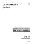
The illustration below shows typical system installation
and cable connections.
R/R-Y
G/Y
B/B-Y
R/R-Y
G/Y
B/B-Y
R/R-Y
G/Y
The system is now ready for operation.
B/B-Y
Hi Carol
Hi Carol
H
V
RGBHV
output
S
H
V
RGBS
output
S
H
V
S
Infrared System
Remote
RS-232 Control
External Genlock
Timing
Component video
output
Outputs
Video output BNC cable connections
Terminator
K
OC
IN
NL
GE
7.
VSC 150 • Installation and Operation
Projector (RGBHV)
2
-23
T RS
OU
or
S
V
EO
VID
O
IDE
0.3A
V
100
C
MA
I
N
P
U
T
S
O
U
O
IDE
T
P S-V
U
T
S
S-V
H
B
RG
Y/Y
/B-
R-Y
-240
A
VG
0 Hz
50/6
Video Editor
(Component)
VSC 150
Video Outputs
Composite
Video
Connect the coax cable from the genlock device (or the
genlock output of another device that shares the
genlock signal) to the Genlock In BNC connector. If
no genlock device will be used, do not attach cables to
these connectors.
If another device in the system will use genlock,
connect the device to the Genlock Out BNC connector
of the VSC 150 as shown in the illustration on the next
page. Otherwise, attach a termination adapter to the
Genlock Out connector. If the genlock signal is
connected to several devices in a daisy chain
2-10
-Y
B/B
G/Y
-Y
R/R
PAL OUT
75 OHM
Connect cables for only one output in addition
to the composite video output. Do not connect
cables to outputs that will not be used for your
application. Connecting cables to more
outputs will overload the circuits and yield
weak signals.
S-video
Videoconferencing
System
VCR
NOTE:
VGA Input
or
Mac Input
Only one S-video or component
video or RGB device may be
connected in addition to the
composite video device and
local monotor.
A typical VSC 150 system application
VSC 150 • Installation and Operation
2-11
Installation and Operation, cont’d
Mac-HV/VGA cable connector pin assignments
The illustration below shows the pin locations on the 15-pin
connectors at opposite ends of the Mac-HV/VGA cable that
is used for connecting the computer to the VSC 150.
6
1
5
10
1
8
posite video and one other), but not the local monitor.
ON — The output is in PAL format.
OFF — The output is in NTSC format.
Size the image to fill the screen
1.
Press the Size button on the front panel.
2.
Rotate the vertical and horizontal Centering/Pan/Size
rotary controls to adjust the vertical and horizontal
size. Observe the picture on screen as you adjust the
controls. The Min/Max LED will light red when the
minimum or maximum limit of a control is reached.
9
15
D15 Pin Locations
Male
11
15
HD15 Pin Locations
Male
VGA (15-pin HD) and Mac (15-pin D) connector
pin locations
The size feature affects both display outputs, but local
monitor loop-out is not affected. The size function
remains active for 8 seconds after the rotary controls
become inactive. The rotary controls then default to
the standard centering and pan functions.
The table below lists signals and their pin assignments for
both the VGA (15-pin HD) and Mac (15-pin D) connectors
of this cable.
VGA Pin
Function
Mac Pin
1
2
3
4
5
6
7
8
9
10
11
12
13
14
15
Red video
Green video
Blue video
ID bit
ID bit
Red ground
Green ground
Blue ground
Not used
Composite & vertical sync gnd
ID bit
ID bit
Horizontal sync
Vertical sync
ID bit/composite sync
2
5
9
4
8
1
6
13
—
11, 14
7
10
15
12
3
Optimizing the Image
After you have installed the scan converter, follow the
procedures in this section in sequence. This will help you
configure the scan converter for the best settings for your
display environment.
Select the output standard
1.
2-12
Select the output standard with the PAL Out DIP
switch. This switch affects both display outputs (com-
VSC 150 • Installation and Operation
3.
Press the Size button again to turn the size feature off.
4.
Center the picture by rotating the vertical and
horizontal Centering/Pan/Size rotary controls.
5.
Repeat steps 1 through 4 as needed.
Select the filtering levels
1.
Press the horizontal, vertical and encoder filtering
controls to select the filtering levels that give the best
picture sharpness and the least amount of flickering.
The LEDs next to each control will light to indicate the
selected level of filtering.
If the filters are set before the image size is adjusted,
you must set the filters again after adjusting the
image size.
Setting Up Genlock and
Vertical Interval Switching
A genlock (black burst generator) device can be connected
to the VSC 150 to synchronize it with other system components for seamless vertical interval switching between sources.
Vertical interval switching setup
For vertical interval switching (to allow clean switching
between signals from several devices during the vertical
blanking period of each signal), a composite sync signal can
be applied at the Genlock In connector, and also passed to
another device via the Genlock Out connector.
VSC 150 • Installation and Operation
2-13
Installation and Operation, cont’d
If the genlock connectors are used only for vertical interval
switching, no horizontal or subcarrier phase adjustments
are required, and the Burst Lock LED does not light.
termination adapter to the other “input” connector, or
by setting the 75 Ohm DIP switch to On (75 ohms).
The Burst Lock LED lights green to indicate that the
VSC 150 is receiving an acceptable genlock (black
burst) sync signal via the Genlock In connector.
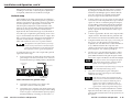
Genlock setup
Genlock differs from simple vertical interval switching in
that an external device (a black burst generator) generates a
reference sync signal for the system, and every device that
uses that signal has its output signal’s horizontal and
subcarrier phases adjusted to exactly match that of the
generator to allow precise timing and full synchronization.
Genlocked systems produce cleaner switches between
inputs than do those without this type of synchronization.
4.
Connect oscilloscope (“scope”) probe A to the Genlock
Out connector. This will provide the scope’s reference
signal. In order to avoid altering the genlock signal,
use the cabling configuration that will be used in the
installation. Either connect the genlock signal cable
from the scope to the next device in the system to be
timed, or provide 75 ohm termination at the scope’s
genlock output.
An oscilloscope is required for genlock setup, and a vectorscope is recommended. Waveform monitors of types other
than a vectorscope may give the appearance that timing is
adjusted correctly when it is 180 degrees out of phase,
which will result in incorrect colors or picture artifacts.
5.
Connect scope probe B to the VSC 150’s composite video
output connector. Ensure that the rear panel PAL Out
DIP switch is set for the desired standard (NTSC/PAL).
6.
Using the instructions for the scope you are using, set
the scope to view the signals’ horizontal phases.
Adjust the VSC 150’s Horz Phase control until there is
no (0º) difference between the composite video
output’s horizontal sync phase and the genlock signal’s
horizontal phase. See “Oscillocope displays”.
7.
Set the scope to view the subcarrier signals. Adjust
the VSC 150’s Sub Phase control until there is a zero
phase difference between the genlock signal and the
NTSC/PAL output. The Burst Lock LED should light.
All equipment in the system must be powered up
and turned on for at least 15 to 20 minutes before
genlock setup adjustments can be made and before
the equipment is used in a genlocked application.
To synchronize the VSC 150’s video output with a genlock
signal, follow these steps:
Power up and turn on all the devices that will use the
genlock signal. The devices must be on for at least 15
to 20 minutes before proceeding with any adjustments.
1.
Computer Video
Signal In
If the Burst Lock LED does not light at this point,
either adjust the horizontal or subcarrier phases
further, or use a different genlock source.
OUT
Timing Source
0.3A
MAC
50/60 Hz
VGA
I
N
P
U
T
S
PAL OUT
75 OHM
100-240 V
R/R-Y
G/Y
GENLOCK
IN
B/B-Y
H
V
S
VIDEO
O
U
T
P S-VIDEO
U
T
S
8.
S-VIDEO
RGB
R-Y/B-Y/Y
The color subcarrier adjustment range is ±90° from
0° for a total adjustment range of 180°.
To Scope Probe B
OUT RS-232
If the Burst Lock LED does not light at all when
genlock is active and the horizontal and subcarrier
phases have been adjusted to match the genlock
signal, do not continue with this procedure. A
different, more stable or time-base-corrected sync
signal must be used for the genlock timing source.
To Scope Probe A
and Termination
Cable connections for genlock setup
2-14
2.
Connect the active timing source signal to the
Genlock In connector on the rear panel.
3.
Connect the active computer video input signal to the
appropriate input as explained in step 2 of the Cabling
section on page 2-9. Ensure that the input is properly
terminated either by connecting a local monitor or a
VSC 150 • Installation and Operation
View the horizontal phases again. If the phase
difference is not zero, repeat steps 6 and 7 until the
settings do not change.
9.
Once the settings are stable and the Burst Lock LED
lights, disconnect the oscilloscope, and reconnect the
genlock cables and terminator to the proper devices in
the system.
VSC 150 • Installation and Operation
2-15
Installation and Operation, cont’d
10.
11.
Check the display(s) for proper colors and for
undesirable artifacts in the image(s). Make
adjustments as necessary. Once the genlock timing
has been adjusted, it should not require readjustment
when changing to a new computer video signal input.
shows black burst only (with no color). The burst vector is
pointing to the left from the center.
340
10
20
30
40
50
310
60
300
70
290
80
280
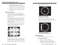
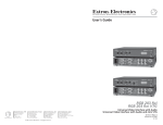
Oscilloscope displays
The figure below shows the genlock input signal (top) and
an out-of-alignment NTSC composite sync output signal
(bottom) displayed on a waveform monitor to check for
alignment. When the phases are aligned, the wave peaks
on the bottom waveform should line up with those in the
reference signal above it.
0
320
If other VSC 150s are part of this genlock daisy chain,
connect the oscilloscope to each device, and repeat
this procedure.
What you see on the oscilloscope while adjusting the
VSC 150 to match the genlock signal depends on the type of
signal used, the type of oscilloscope, and the procedure the
scope requires. This section shows some examples of
oscilloscope displays.
350
330
270
90
260
100
250
110
240
120
230
130
220
140
210
150
200
190
180
170
160
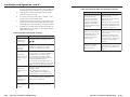
Vectorscope screen during
horizontal phase adjustment
The figure below shows an example of a view of a
vectorscope during adjustment of the color subcarrier
phase (SC/H). The subcarrier phase should be aligned to 0º
(indicated in the figure by the triangle).
With this method there is no way to know if the signals are
180º out of phase. A delayed sweep on a time-based scope
would allow a more accurate display of the input and
output signal phase relationships.
340
350
0
10
20
30
330
A1+40
40
320
50
310
60
300
A2
70
290
80
280
A3
B1
270
90
260
100
250
110
240
B2
120
230
-40
130
220
140
210
B3
150
200
190
180
170
160
Vectorscope screen during
color subcarrier phase adjustment
Troubleshooting
Superimposed waveforms
A vectorscope is more accurate than a waveform monitor.
The next figure shows an example of a vectorscope display
when the horizontal phase is adjusted to align it with the
burst (genlock) vector. Adjust the Horz Phase control until
the difference between the two vectors is 0º. This example
2-16
VSC 150 • Installation and Operation
The image should appear properly on the screen(s).
If the image does not appear
1.
Ensure that all devices are plugged in.
2.
Make sure that each device is receiving power.
3.
Check the cabling, wiring and grounding, and make
adjustments as needed. Ensure that the rear panel
output selection toggle switch and PAL Out DIP switch
VSC 150 • Installation and Operation
2-17
Installation and Operation, cont’d
are set for the formats that match the cable configuration
and the requirements of the display/recording devices.
4.
Verify that the 75 Ohm video input termination DIP
switch has been set correctly.
5.
To test the system setup and output, substitute a video
test generator for the computer input.
6.
Confirm that the input is receiving a signal with a compatible scan rate (horizontal frequency between 24 kHz
and 70 kHz, and a vertical frequency of 50 Hz to 120 Hz).
7.
Call Extron’s customer support hotline if needed. Be
prepared to discuss the steps you have taken and the
equipment involved.
If the image does not display correctly
Symptoms
Solutions
The picture is
shifted off the
screen edges.
Adjust the centering and sizing controls
( ,
).
The image is
stable, but it has
ghosting or
blooming.
Change the 75 ohm/high Z video input
termination. If that doesn’t solve the
problem, use a different input cable.
The picture is
faint or cuts out,
and the signal is
weak.
2-18
If the scan converter does not respond to controls
Symptoms
Solutions
The picture does not move
on screen when the
horizontal and vertical
centering controls are
rotated, and the filtering
settings do not change
when the filtering controls
are pressed.
The VSC 150 may be set for
Executive mode.
The VSC 150 responds to
adjustments made via the
front panel, but not to
selections from the IR
remote control.
There is no response to
commands from the
RS-232 controller.
Adjustments can be made via
RS-232 control, or...
Executive mode can be turned
off by pressing the Freeze and
Size controls simultaneously for
2 seconds. See page 2-4.
Signals from the IR 601 remote
control may not be reaching the
scan converter.
Change the placement of the
equipment so the signals have a
clear transmission path between
the remote control and the
VSC 150.
Ensure that the baud rate
(9600 baud) and communication
protocol are set correctly. See
page 3-2.
Video input may be double-terminated. If
a local monitor or a termination adapter is
attached to the local monitor output
connector, make sure that the 75 Ohm
video input termination DIP switch is set
to Off (for high Z termination).
Disconnect all unused output cables. Do
not connect cables to both the S-video and
RGB/component outputs at the same time.
The picture
appears without
color.
Adjust the hue/tint and color controls on
the display device.
Make sure that the video display/
recording equipment is using the same
standard (NTSC or PAL) as the VSC 150.
In a genlocked
system,
displayed color
is incorrect.
The color subcarrier phase (Sub Phase)
might require readjustment.
The image still
does not display
correctly.
Call Extron’s customer support hotline.
VSC 150 • Installation and Operation
VSC 150 • Installation and Operation
2-19
Installation and Operation, cont’d
VSC 150
3
Chapter Three
Remote Control
RS-232 Remote Control
IR Remote Control
2-20
VSC 150 • Installation and Operation
Remote Control,
Remote
Controlcont’d
The VSC 150 can be remotely controlled via a computer or a
control panel attached to the rear panel RS-232 connector.
Alternatively, the VSC 150 can be controlled using the IR
601 infrared remote control. This chapter discusses how to
use each of these options to control the scan converter.
RS-232 Remote Control
The VSC 150 displays the copyright message when it first
powers on. Vx.xx is the firmware version number.
RECONFIG
The VSC 150 sends the Reconfig message
when the input source is changed and when changes have
been made to one or more of the settings.
VSC error responses
The VSC 150 can be controlled by a host computer or other
control device via an RS-232 connection with a protocol of
9600 baud, 1 stop bit, no parity, and no flow control. The
5
1
control device (host) can use either Extron’s
Simple Instruction Set (SIS) or the graphical
9
6
control program for Windows.
DB9 Pin Locations
Female
The rear panel RS-232 9-pin D connector has the following
pin assignments:
Pin
RS-232 function
Description
1
2
3
4
5
6
7
8
9
–
Tx
Rx
–
Gnd
–
–
–
–
Not used
Transmit data
Receive data
Not used
Signal ground
Not used
Not used
Not used
Not used
Host-to-VSC communications
SIS commands consist of one or more characters per field.
No special characters are required to begin or end a
command sequence. When the VSC 150 determines that a
command is valid, it executes the command and sends a
response to the host device. All responses from the scan
converter to the host end with a carriage return and a line
feed (CR/LF = ), which signals the end of the response
character string. A string is one or more characters.
When the VSC 150 receives a valid SIS command, it
executes the command and sends a response to the host
device. If the VSC 150 is unable to execute the command
because the command is invalid or it contains invalid
parameters, it returns an error response to the host. The
error response codes and their descriptions are as follows:
E10 – Invalid command
E11 – Invalid preset number
E13 – Invalid value (the number is out of range).
Time-out
A delay of 10 or more seconds between command sequence
characters causes a time-out. The command operation is
stopped, and there is no indication that a time-out occurred.
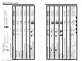
Using the command/response table
The command/response table on the next page lists valid
command ASCII codes, the VSC 150’s responses to the host,
a description of the command’s function or the results of
executing the command, and an example of each command.
Lower case characters are acceptable in the command field
only where indicated.
The ASCII to HEX conversion table below is for use with
the command/response table.
ASCII to HEX Conversion Table
•
VSC-initiated messages
When a local event such as a front panel selection or
adjustment takes place, the VSC 150 responds by sending a
message to the host. No response is required from the host.
The VSC-initiated messages are listed here (underlined).
(C) COPYRIGHT 1999, EXTRON ELECTRONICS, VSC 150,
Vx.xx
3-2
VSC 150 • Remote Control
VSC 150 • Remote Control
3-3
3-4
VSC 150 • Remote Control
X1 + 44
7B + 44
7D + 44
7B + 3B
7D + 3B
7B + 3A
7D + 3A
7B + 2F
7D + 2F
7B + 48
7D + 48
X
x
F
f
X4
X4
,
.
e
{e
}e
X3
d
{d
}d
X2
2C
2E
58
78
46
66
X4
X4
X3 + 65
7B + 65
7D + 65
X2 + 64
7B + 64
7D + 64
Command
ASCII
Hex
D
{D
}D
X1
{;
};
{:
}:
{/
}/
{H
}H
Command
ASCII
Hex
X5
X4
X3
X2
Query firmware version number
Request part number
Request information
Command =
Response =
Q/q
N/n
I/i
Dhz
51/71
4E/6E
49/69
X1 • Dvt
X2
X1
X1
X1
X4
X4
X3
X3
X3
X2
X2
X2
Exe 1
Exe 0
Frz 1
Frz 0
Spr
Rpr
Enc
Enc
Enc
Dvt
Dvt
Dvt
(VSC to host)
Response
Dhz
Dhz
Dhz
Vsz +
Vsz -
Hsz +
Hsz -
Vph +
Vph -
Hph +
Hph -
(VSC to host)
X5
Reset to factory default
Display firmware version
Display VSC 150’s part #
Display status
Enable executive
Disable executive
Enable freeze
Disable freeze
Specific value
Increment up
Increment down
Specific value
Increment up
Increment down
Additional
description
Specific value
Increment up
Increment down
Increment up
Increment down
Increment up
Increment down
Increment up
Increment down
Increment up
Increment down
Additional
description
Vertical filtering level (1 through 3)
Encoder filtering level (1 through 3)
Memory presets (1 through 3)
1 = On, 0 = Off
Response
=
=
=
=
Zap
Ver x.xx
N60-312-01
(see below)
• Enc X3 • Frz X5 • Exe
Firmware version, part number & information requests, and reset
System reset
Esc z
1B 7A 0D
Set Executive mode to On
Set Executive mode to Off
Executive mode
Set Freeze mode to On (freeze the displayed image)
Set Freeze mode to Off (release the displayed image)
Freeze
Save preset
Recall preset
Memory
Select encoder filter X3 (Enc)
Select next higher encoder filter (Enc + 1)
Select next lower encoder filter (Enc - 1)
Encoder filter (detail)
Select vertical filter X2 (Dvt)
Select next higher vertical filter (Dhz + 1)
Select next lower vertical filter (Dhz - 1)
Vertical filter (detail)
Command description
Select horizontal filter X1 (Dhz)
Select next higher horizontal filter (Dhz + 1)
Select next lower horizontal filter (Dhz - 1)
Horizontal filter (detail)
Increase vertical size by one step
Decrease vertical size by one step
Vertical size
Increase horizontal size by one step
Decrease horizontal size by one step
Horizontal size
Shift down one step
Shift up one step
Vertical shift
Shift right one step
Shift left one step
Horizontal shift
Command description
Command/response table
Symbol definitions
= CR/LF (carriage return/line feed)
= CR (carriage return only)
• = Space
X1 = Horizontal filtering level (1 through 2)
Remote Control, cont’d
VSC 150 • Remote Control
3-5
Remote Control, cont’d
Control software for Windows
The included graphical control software for Windows offers
another way to control the VSC 150 via RS-232 connection
in addition to the Simple Instruction Set commands listed
on pages 3-4 to 3-5. The control software is compatible with
Windows 3.1/3.11, Windows 95/98 and Windows NT. The
VSC 150 uses version 3.1 or higher of Extron’s VSC and
DDS Control Program, which is included with the VSC 150.
Installing the software
The control program is contained on a single 3.5-inch
diskette, and it can run from the floppy drive. However, it
is more convenient to run the program from the hard drive.
To install the software on the hard drive, run SETUP.EXE
from the floppy disk, and follow the instructions that
appear on the screen. The program requires approximately
1 MB (megabyte) of hard disk space.
By default the installation creates a C:\VSC200 directory,
and it places two icons (VSC + DDS Control Pgm and
VSC + DDS Help) into a group or folder named “Extron
Electronics”.
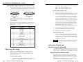
Using the software
1.
To run the VSC and DDS Control Program, doubleclick on the VSC + DDS Control Pgm
icon in the Extron Electronics group or
folder. The Comm menu appears on the
screen.
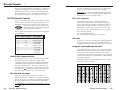
2.
Click on the comm port that is connected to the
VSC 150’s RS-232 port. The Extron VSC and DDS
Control Program window appears. It displays the
current settings. See the illustration on the next page.
VSC and DDS Control Program window
IR Remote Control
The IR 601 infrared remote control can perform all the
functions that are available via the front panel controls
except the genlock adjustments.
The IR 601 remote control can freeze
the image, set filtering adjustments,
zoom in and out, resize and shift the
image. The push-buttons for these
functions on the IR 601 work exactly
like those on the VSC 150’s front
panel. To function properly, the line
of sight between the IR controller and
the VSC 150 must be unobstructed.
The Power/signal lock LED
blinks while the VSC 150
receives commands from the
IR 601.
For information on program features, press the F1
computer key or click on the Help menu from
within the control program, or double-click
on the VSC + DDS Help icon in the Extron
Electronics group or folder.
If the VSC 150 is set for
Executive mode,
adjustments can be made
via the IR remote control.
The IR 601 remote
3-6
VSC 150 • Remote Control
All controls except Freeze
will be locked on the IR 601
while Freeze mode is active.
Press the Freeze button
again to turn off Freeze
mode and unlock the other
controls.
VSC 150 • Remote Control
3-7
Remote Control, cont’d
Using the memory feature
In addition to performing the basic functions, the IR 601
remote control provides a memory storage and recall
feature. The VSC 150 offers 30 factory-defined presets and
30 user-defined memory presets that store combinations of
size, zoom, panning, centering and filtering settings. These
settings are recalled automatically in association with a
particular input signal scan rate.
The VSC 150 also offers three additional user-defined
presets that can be recalled manually via IR 601 or RS-232
remote control.
The IR 601 has four Memory buttons for storing and
recalling up to three presets. To store and recall
combinations of settings with the IR 601, follow these steps:
1.
Set the sizing/zoom, centering and filtering settings
for the desired computer video source by using the
front panel controls, RS-232 commands, or the IR 601
controls.
2.
Press the Store button in the Memory area of the
IR 601 control. The Power/signal lock LED flashes for
4 seconds. During that period, press the button
labeled with the number (1, 2 or 3) corresponding to
the desired memory. The image settings are stored in
a user memory slot corresponding to that number. If
the button is pressed after the LED stops flashing, the
settings are not stored.
3.
To recall a setup that has been stored in memory, press
the appropriate numbered Memory button. The
combination of zoom, sizing and filtering level
settings are recalled.
The same three user-defined presets can also be saved and
recalled using the RS-232 control. To store and recall these
memory presets via RS-232 control, follow these steps:
1.
2.
3-8
Set the sizing/zoom, centering and filtering settings
for the desired computer video source by using the
front panel controls, RS-232 commands, or the IR 601
controls.
Use the memory commands in the Command/
response table on page 3-5 to save or recall the presets.
VSC 150 • Remote Control
VSC 150
A
Appendix
Specifications
Accessories and Part Numbers
Specifications
Included Parts
Accessories
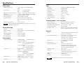
Specifications, cont’d
Specifications
Video input
Sync
Number/signal type ................... 1 VGA, 1 Mac analog RGBHV, RGBS,
RGsB
Connectors .................................... VGA ........... 15-pin HD female
Mac ............ 15-pin D female
Minimum/maximum level(s) .... Analog ....... 0V to 2.0V p-p with no offset
Impedance .................................... 75 ohms or High Z (DIP switch-selectable)
Horizontal frequency .................. Autoscan 24 kHz to 71 kHz
Vertical frequency ....................... Autoscan 50 Hz to 120 Hz
Resolution range .......................... Autoscan 560 x 384 to 1280 x 1024
Note: 1280 x 1024 is available at 60 Hz
only.
External sync (genlock) ............... 0.3V to 1.0V p-p
The color subcarrier adjustment range is ±90° from 0° for a total
adjustment range of 180°.
Video processing
Encoder .........................................
Digital sampling ..........................
Colors ............................................
Horizontal filtering ......................
Vertical filtering ...........................
Encoder filtering ..........................
10 bit digital
24 bit, 8 bits per color; 50 MHz standard
16.8 million
2 levels (selectable)
3 levels (selectable)
3 levels (selectable)
Video output
Number/signal type ................... 1 RGBHV/RGBS ...... 15.75 kHz analog, or
1 component video, or
1 S-video .... NTSC, 15.75 kHz, 525 lines, or
PAL, 15.5 kHz, 625 lines
1 composite video ....
NTSC, 15.75 kHz, 525 lines, or
PAL, 15.5 kHz, 625 lines
Connectors .................................... RGBHV/RGBS ......... 6 BNC female
S-video ....... 1 4-pin mini-DIN female
Component video (YUV) .......
3 BNC female
(uses the R, G, and B BNCs)
Composite video ...... 1 BNC female
Nominal level ............................... RGBHV/RGBS, component .. 0.7V p-p
S-video, composite video ...... 1.0V p-p
Impedance .................................... 75 ohms
A-2
VSC 150 • Specifications
Input type .....................................
Output type ..................................
Genlock connectors .....................
Standards ......................................
Input level .....................................
Output level ..................................
Input impedance ..........................
Output impedance .......................
Polarity ..........................................
Autodetect RGBHV, RGBS, RGsB
RGBHV, RGBS
2 BNC female
NTSC 3.58, PAL
1.5V to 5.0V p-p
TTL ............. 5.0V p-p
75 ohms
75 ohms
Negative
Control/remote — scan converter
Serial control port ........................
Baud rate and protocol ...............
Serial control pin configurations .
IR controller module ...................
Program control ...........................
RS-232, 9-pin female D connector
9600, 8-bit, 1 stop bit, no parity
2 = TX, 3 = RX, 5 = GND
Extron’s IR 601
Extron’s control program for Windows®
Extron’s Simple Instruction Set™ – SIS™
General
Power ............................................. 100VAC to 240VAC, 50/60 Hz, 40 watts,
internal, auto-switchable
Temperature/humidity .............. Storage -40° to +158°F (-40° to +70°C) /
10% to 90%, non-condensing
Operating +32° to +122°F (0° to +50°C) /
10% to 90%, non-condensing
Rack mount ................................... Yes, with optional rack shelf,
part #60-190-01
Enclosure type .............................. Metal
Enclosure dimensions ................. 1.75" H x 8.75" W x 9.50" D
4.45 cm H x 22.23 cm W x 24.13 cm D
(Add 0.5” for front panel knobs and
0.75” for rear panel connectors.)
Shipping weight ........................... 5 lbs (2.3 kg)
Vibration ....................................... ISTA/NSTA 1A in carton
(International Safe Transit Association)
Approvals ..................................... UL, CUL, CE, FCC Class A
MTBF ............................................. 30,000 hours
Warranty ....................................... 2 years parts and labor
Specifications are subject to change without notice.
VSC 150 • Specifications
A-3
Accessories and
Part
Numbers,
cont’d
Accessories
and
Part
Numbers
Included Parts
These items are included in each order for a VSC 150:
Included parts
Part number
VSC 150
60-312-01
Mac-HV/VGA cable (6 feet)
26-462-01
S-video cable (6 feet)
26-316-02
75 ohm BNC termination adapter
26-300-01
IR 601 remote controller
VSC 150 User’s Manual
68-469-01
VSC/DDS control software for Windows
version 3.1 or higher
29-038-01
Accessories
A-4
Accessories
Part number
1U rack shelf
60-190-01
VSC 150 • Accessories and Part Numbers
VSC 150 • Accessories and Part Numbers
A-5
Accessories and Part Numbers, cont’d
A-6
VSC 150 • Accessories and Part Numbers