1
Maintenance Manual
MUTOH EUROPE N.V.
AP-74038, Rev 1.1 : , 25/01/2005
Rockhopper 38 – Maintenance Manual
2
AP-74038, Rev. 1.1, 25/01/05
Rockhopper 38 – Maintenance Manual
COPYRIGHT NOTICE
COPYRIGHT © 2005 Mutoh Europe N.V. All rights reserved.
This document may not be reproduced by any means, in whole or in part, without written permission of the
copyright owner.
This document is furnished to support the Mutoh’s Rockhopper 38 Printer. In consideration of the furnishing
of the information contained in this document, the party to whom it is given, assumes its custody and control
and agrees to the following:
The information herein contained is given in confidence, and any part thereof shall not be copied or
reproduced without written consent of Mutoh Europe N.V.
This document or the contents herein under no circumstances shall be used in the manufacture or
reproduction of the article shown and the delivery of this document shall not constitute any right or license to
do so.
January 2005
Published: Mutoh Europe N.V., Archimedesstraat 13, B-8400 Oostende, BELGIUM
3
AP-74038, Rev. 1.1, 25/01/05
Rockhopper 38 – Maintenance Manual
4
AP-74038, Rev. 1.1, 25/01/05
Rockhopper 38 – Maintenance Manual
Important Notice
This product has been tested and found to comply with the limits for a Class A digital device, pursuant to Part
15 of FCC Rules. These limits are designed to provide reasonable protection against harmful interference
when the product is operated in a commercial environment.
This product generates, uses, and can radiate radio frequency energy and if not installed and used in
accordance with this manual, may cause harmful interference to radio communications. Operation of this
product in a residential area is likely to cause harmful interference in which case the user will be required to
correct the interference at his expense.
1.
Radio interfere
Product generates weak radio signals and may interfere with television reception and utilities. If a
product does interfere with radio or TV reception, try following:
Change the direction of your radio and TV reception antenna or feeder.
Change the direction of the product.
Move either the product or the receiving antenna so there is more distance between them.
Be sure the product and the receiving antenna are on separate power lines.
2.
Trademark mentioned in this manual.
MUTOH, Rockhopper 38, Eco-Solvent Plus, MH-GL, MH-GL2, MH-RTL are registered trademarks
or product names of MUTOH INDUSTRIES LTD.
Centronics and Bitronics are registered trademarks or product names of Centronics Data Computer
Corporation.
Windows 95, Windows 98, Windows Me, Windows XP, Windows NT4.0, Windows2000, and
MSDOS are registered trademarks or product names of Microsoft Corporation.
DOS/V is registered trademark and product name of International Business Machine Corporation
(IBM).
Other company and product names may be registered trademarks or product names.
No part of this product or publication may be reproduced, copied or transmitted in any form or by any means,
except for personal use, without the permission of MUTOH EUROPE N.V.
The product and the contents of this publication may be changed without prior notification.
MUTOH EUROPE N.V. has made the best efforts to keep this publication free from error, but if you find any
uncertainties or misprints, please call us or the shop where you bought this equipment.
MUTOH EUROPE N.V. shall not be liable for any damages or troubles resulting from the use of this
equipment or this manual.
5
AP-74038, Rev. 1.1, 25/01/05
Rockhopper 38 – Maintenance Manual
6
AP-74038, Rev. 1.1, 25/01/05
Rockhopper 38 – Maintenance Manual
Table of contents
1. Safety Instructions....................................................................................................... 11
1.1. Introduction .......................................................................................................................... 11
1.2. Warnings, Cautions and Notes ............................................................................................ 11
1.3. Important safety instructions ................................................................................................ 11
1.4. Warning labels ..................................................................................................................... 14
2. Product Overview ........................................................................................................17
2.1. Getting to know the Printer parts and components .............................................................. 17
2.1.1 Explanation of fixer and dryer ........................................................................................................ 18
2.2. Guided tour around the operation panel .............................................................................. 19
2.2.1. Keyboard Concept ........................................................................................................................ 23
2.2.2. Menu Structure – overview ........................................................................................................... 24
2.3. Heater system operation panel ............................................................................................ 25
3. Specifications...............................................................................................................27
3.1. Introduction .......................................................................................................................... 27
3.2. Product Specifications ......................................................................................................... 27
3.3. Interface Specifications ........................................................................................................ 28
3.4. Installation............................................................................................................................ 30
4. Parts Replacement.......................................................................................................33
4.1. Introduction .......................................................................................................................... 33
4.2. Removal of covers ............................................................................................................... 34
4.2.1 Removing right cover .................................................................................................................... 35
4.2.2 Removing the left cover ................................................................................................................ 35
4.2.3 Removing the Front Cover............................................................................................................ 35
4.2.4 Removing the Unit Panel Cover ................................................................................................... 36
4.2.5 Removing the Heater Panel Cover ................................................................................................ 36
4.2.6 Removing the Y Rail Cover........................................................................................................... 36
4.2.7 Removing the Front Paper Guide ................................................................................................. 37
4.2.8 Removing the Rear Paper Guide.................................................................................................. 37
4.2.9 Removing the Right Side Cap ...................................................................................................... 37
4.2.10 Removing the Left Side Cap....................................................................................................... 38
4.2.11 Opening and closing the Control Box .......................................................................................... 38
4.2.12 Removing the Head Cover .......................................................................................................... 39
4.3 Replacement of Board Assemblies ....................................................................................... 40
4.3.1 Replacing the Switch Cable Assembly / DC Cable Assembly....................................................... 40
4.3.2 Replacing the Main Board Assembly............................................................................................. 42
4.3.3 Replacing the Power Supply Board. .............................................................................................. 44
4.3.4 Replacing the Control Panel Board Assembly............................................................................... 45
4.3.5 Replacing the Control Panel Cable................................................................................................ 46
4.3.6 Replacing the Heater Board Assembly.......................................................................................... 47
4.3.7 Replacing the Heater Panel Cable ................................................................................................ 48
4.3.8 Replacing the Mother Board Assembly ......................................................................................... 49
4.3.9 Replacing the extended memory (8Mb) (16Mb) (32 Mb)............................................................... 50
7
AP-74038, Rev. 1.1, 25/01/05
Rockhopper 38 – Maintenance Manual
4.4. Replacement of PF Driving Section Components................................................................ 51
4.4.1 Replacing the X Motor Assembly................................................................................................... 51
4.4.2 Replacing the Fan Assembly and Fan Cables............................................................................... 52
4.4.3 Replacing the Speed Reduction Belt ............................................................................................. 54
4.4.4. Replacing the Lever Sensor Assembly......................................................................................... 55
4.4.5 Replacing the Cover Switch Assembly .......................................................................................... 57
4.4.6 Replacing the Waste Bottle Fluid Sensor Assembly ..................................................................... 58
4.4.7 Replacing the Front Paper Sensor Assembly................................................................................ 59
4.4.8 Replacing the Rear Paper Sensor Assembly ................................................................................ 60
4.4.9 Replacing the Grid Roller Assembly and Coupling Assembly ....................................................... 62
4.4.10 Replacing the Pressure Assembly............................................................................................... 63
4.4.11 Replacing the Blade..................................................................................................................... 66
4.4.12 Replacing the Pressure Rollers ................................................................................................... 66
4.4.13 Platen Height Adjustment ............................................................................................................ 67
4.5 Replacement of CR Driving Section Components ................................................................ 68
4.5.1 Replacing the Y Motor Assembly................................................................................................... 68
4.5.2 Replacing the Steel Belt................................................................................................................. 69
4.5.3 Replacing the T fence .................................................................................................................... 69
4.5.4 Replacing the Steel Flexible Guide Assembly............................................................................... 71
4.5.5 Replacing the Cursor Plate Spring ................................................................................................ 72
4.5.6 Replacing the Y Return Pulley Assembly ...................................................................................... 73
4.6 Replacing the Maintenance Area .......................................................................................... 74
4.6.1 Replacing the Pump Motor Assembly............................................................................................ 74
4.6.2 Replacing the Cap Assembly......................................................................................................... 75
4.6.3 Replacing the Wiper....................................................................................................................... 76
4.6.4 Replacing the Pump Assembly...................................................................................................... 77
4.6.5 Replacing the Maintenance Station Assembly .............................................................................. 79
4.7 Replacement of Ink Supply Section Components................................................................. 80
4.7.1 Replacing the Cartridge Frame Assembly ..................................................................................... 80
4.7.2 Replacing the Ink ID assembly (Black, Yellow, Magenta, Cyan)................................................... 84
4.7.3 Replacing the Detector Assembly (Black, Yellow, Magenta and Cyan) ........................................ 85
4.7.4 Replacing the Y Cable ................................................................................................................... 85
4.7.5 Replacing the Ink Tubes ................................................................................................................ 88
4.7.6 Replacing the O-rings (Small) and (Large) .................................................................................... 89
4.7.7 Replacing the Tube Guide Assembly ............................................................................................ 91
4.8 Replacement of Cartridge Area............................................................................................. 92
4.8.1 Replacing the Cutter Solenoid Assembly ...................................................................................... 92
4.8.2 Replacing the Print Head Assembly and Head Cable (Black)....................................................... 93
4.8.3 Replacing the Print Head Assembly and Head Cable (color)........................................................ 96
4.8.4 Replacing the Y Paper Sensor Assembly...................................................................................... 98
4.8.5 Replacing the Head Board Assembly ............................................................................................ 99
4.8.6 Replacing the Dampers (Black and Colour) ................................................................................ 100
4.8.7 Replacing the Cursor Assembly .................................................................................................. 102
4.8.8 Replacing the Origin Sensor Assembly ....................................................................................... 103
4.8.9 Removing the Scroller from the printer ........................................................................................ 104
4.8.10 Replacing the cutter blade ......................................................................................................... 104
4.9 Replacement of Support and Scrollers ............................................................................... 106
4.9.1 Replacing the head height sensor. .............................................................................................. 106
4.9.2 Replacing the Junction Board Assembly ..................................................................................... 107
4.9.3 Replacing the Network Interface Board (Optional Item) .............................................................. 108
4.10 Replacement of heater system ......................................................................................... 109
4.10.1 Replacing the fixer heater strip .................................................................................................. 109
4.10.2 Replacing the dryer heater strip................................................................................................. 111
8
AP-74038, Rev. 1.1, 25/01/05
Rockhopper 38 – Maintenance Manual
5. Self-Diagnosis Function............................................................................................ 113
5.1 Introduction ......................................................................................................................... 113
5.2 Preparation ......................................................................................................................... 114
5.2.1 Preparation on machine............................................................................................................... 114
5.2.2 Starting up.................................................................................................................................... 114
5.3 Examination ........................................................................................................................ 115
5.3.1 Memory Capacity ......................................................................................................................... 115
5.3.2 Version ......................................................................................................................................... 115
5.3.4 Sensors ........................................................................................................................................ 116
5.3.5 Encoders ................................................................................................................................... 117
5.3.6 Fans ............................................................................................................................................. 117
5.3.7 Ethernet Board............................................................................................................................. 117
5.3.8 History .......................................................................................................................................... 118
5.3.9 Head Waveform ........................................................................................................................... 119
5.4 Adjustment .......................................................................................................................... 120
5.4.1 Adjusting the capping position ..................................................................................................... 120
5.4.2 Check Media Skew ...................................................................................................................... 121
5.4.3 How to Enter Head Rank ............................................................................................................. 122
5.4.4 How to Check Head Nozzles ....................................................................................................... 123
5.4.5 How to Check Black Head Tilt ..................................................................................................... 125
5.4.6 How to Check Colour Head Tilt ................................................................................................... 126
5.4.7 How to Align Repeatability Printing Position................................................................................ 127
5.4.8 How to Adjust CW........................................................................................................................ 129
5.4.9 How to Adjust the Flush Pointer .................................................................................................. 131
5.4.10 How to Adjust the Media Transport Distance ............................................................................ 132
5.4.11 How to Adjust Front-to-Head, Cutter-to-Head Distances .......................................................... 133
5.4.12 How to Adjust the Rear Sensor Position.................................................................................... 134
5.4.13 How to make a Test Print........................................................................................................... 135
5.4.14 Head Cleaning ........................................................................................................................... 136
5.5 Cleaning .............................................................................................................................. 137
5.5.1 Normal.......................................................................................................................................... 137
5.5.2 Powerful ....................................................................................................................................... 137
5.6 Test Printing ........................................................................................................................ 138
5.6.1 Head Printing Verification ............................................................................................................ 138
5.6.2 Adjustment Parameters ............................................................................................................... 138
5.7 Parameters ......................................................................................................................... 139
5.7.1 How to Initialize Parameters ........................................................................................................ 139
5.7.2 How to Update Parameters. ........................................................................................................ 140
5.7.3 How to Update the Capping Position Parameter......................................................................... 140
5.7.4 How to Update the Head Rank Parameter .................................................................................. 141
5.7.5 How to Update the Print Positioning Parameter .......................................................................... 141
5.7.6 How to Update the Media Transport Distance Parameter........................................................... 142
5.7.7 How to Update the Mechanical Parameters ................................................................................ 142
5.8 Aging................................................................................................................................... 143
5.8.1 Carriage motor ............................................................................................................................. 143
5.8.2 Media Feed .................................................................................................................................. 144
5.8.3 Cutter ........................................................................................................................................... 144
5.8.4 Maintenance Unit ......................................................................................................................... 144
5.8.5 Head............................................................................................................................................. 145
6. Maintenance Mode.....................................................................................................147
6.1. Introduction ........................................................................................................................ 147
6.2. Operating Maintenance Mode............................................................................................ 147
6.2.1. Starting Up Maintenance Mode .................................................................................................. 147
6.2.2. Operating Maintenance Mode .................................................................................................... 147
6.3. Maintenance Menu ............................................................................................................ 148
6.3.1. Counter Display Menu ................................................................................................................ 148
6.3.2. Counter Initialization Menu ......................................................................................................... 150
6.3.3. MAC address write enable menu................................................................................................ 150
9
AP-74038, Rev. 1.1, 25/01/05
Rockhopper 38 – Maintenance Manual
7. Adjustments ...............................................................................................................153
7.1. Introduction ........................................................................................................................ 153
7.2 Adjustments ........................................................................................................................ 153
7.2.1 Steel Belt Tension Adjustment..................................................................................................... 153
7.2.2 How to Adjust X Speed Reduction Belt Tension ......................................................................... 154
7.2.3 Tilt of the Print Head Adjustment (Black)..................................................................................... 155
7.2.4 Tilt of the Print Head Adjustment (colour).................................................................................... 159
7.2.5 Capturing and installing Backup Parameters............................................................................... 162
7.2.6 Install a Program (Software Upgrade) ......................................................................................... 163
7.2.7 Y Rail Fitting Precision measurement.......................................................................................... 164
7.2.8 Head Cleaning Procedure 1 ........................................................................................................ 166
7.2.9 How to check the Power Supply Voltages/ 100 V AC, 200 V AC ................................................ 168
7.2.10 How to check the Power Supply Voltages / 5 V DC .................................................................. 169
7.2.11 How to Check the Power Supply Voltages/24 V DC and 42 V DC............................................ 170
7.2.12 Cleaning the Head Nozzle Face ................................................................................................ 172
7.2.13 Replacing X Speed Reduction Pulley Assembly ....................................................................... 173
8. Maintenance ...............................................................................................................175
8.1 Transporting the printer....................................................................................................... 175
8.1.1 How to move on the same floor or by elevator to another floor................................................... 175
8.1.2 How to move to a different building by vehicle ............................................................................ 176
8.2 Daily maintenance .............................................................................................................. 177
8.2.1 How to clean the printer unit ........................................................................................................ 177
8.2.2 Replacing the ink Cassettes ........................................................................................................ 179
8.2.3 Replacing the cutting blade ......................................................................................................... 180
8.2.4 Emptying the waste bottle............................................................................................................ 182
8.2.5. Replacing the blades .................................................................................................................. 183
8.3 Periodical Services ............................................................................................................. 184
8.3.1. Service by end-user .................................................................................................................... 184
8.3.2. Service by authorised Mutoh technician ..................................................................................... 184
9. Troubleshooting ...........................................................................................................185
9.1. Introduction ........................................................................................................................ 185
9.2 Errors when message is displayed ..................................................................................... 186
9.2.1 Printer Status Messages.............................................................................................................. 186
9.2.2 Data Errors................................................................................................................................... 198
9.2.3 Command Errors.......................................................................................................................... 199
9.2.4 CPU system faults ....................................................................................................................... 200
9.2.5 Heater Errors ............................................................................................................................... 206
9.3 Errors when message is not displayed ............................................................................... 208
9.3.1 Trouble with Initialization.............................................................................................................. 208
9.3.2 Trouble with Media Feed. ............................................................................................................ 215
9.3.3 Trouble with printing..................................................................................................................... 217
9.3.4 Problem Involving Noise .............................................................................................................. 233
9.3.5 Trouble with Media Cutting .......................................................................................................... 236
9.3.6 Online/Function Problems............................................................................................................ 239
9.3.7 Other ............................................................................................................................................ 241
9.4 Heater Error Messages ....................................................................................................... 245
9.4.1 Automatic Check.......................................................................................................................... 245
9.4.2 Error Messages............................................................................................................................ 246
10. Appendix...................................................................................................................247
10.1. Introduction ...................................................................................................................... 247
10.2. Wiring Diagram Rockhopper 38 ....................................................................................... 247
10.3. Rockhopper 38 : Service Parts List/Exploded Views/Configuration Diagrams................. 248
10
AP-74038, Rev. 1.1, 25/01/05
Rockhopper 38 – Maintenance Manual
1. SAFETY INSTRUCTIONS
1.1. INTRODUCTION
This chapter explains the meaning of safety terms for personnel who operate this equipment, important
safety instructions and the positions of the warning labels.
Important :
Be sure to follow all instructions and warnings on this manual when using the
equipment.
1.2. WARNINGS, CAUTIONS AND NOTES
Safety terms in this manual and the contents of warning labels attached to the printer are categorized into
the following three types depending on the degree of risk (or the scale of accident).
Read the following explanations carefully and follow the instructions in this manual.
Safety terms
Important
Caution
Notes
Details
Must be followed carefully to avoid death or serious bodily injury
Must be observed to avoid bodily injury (moderately or lightly) or damage to your
equipment
Contains important information and useful tips on the operation of your printer
1.3. IMPORTANT SAFETY INSTRUCTIONS
General safety instructions that must be observed to use the equipment safely are explained below.
Do not place the printer in the following areas. Doing so may result in the printer tipping or falling over
and causing injury.
o Unstable surfaces
o Angled place
o Areas subject to vibration by other equipment
Do not stand on or place heavy objects on your printer. Doing so may result in the printer tipping or
falling over and causing injury.
Do not cover the ventilation hole of your printer with cloth, such as a blanket or table cloth. Doing so
could obstruct ventilation and cause fire.
Do not place the printer in humid and dusty areas. Doing so may result in electrical shock or fire.
Do not use a damaged power cable. Doing so may result in electrical shock.
Do not attempt to plug in electrical plugs with wet hands. Doing so may result in electrical shock.
11
AP-74038, Rev. 1.1, 25/01/05
Rockhopper 38 – Maintenance Manual
Do not connect earth cables in the following areas.
Gas pipes → Doing so may cause fire or an explosion.
Earth terminals for telephone line or lightening rod → Doing so may cause a large flow of voltage if
lightening occurs.
• Water pipes or faucets → If there is a plastic part in the pipe, the earth will not work properly.
•
•
Do not insert or drop metal or inflammable objects into openings, such as ventilation outlets. Doing so
may result in electrical shock and fire.
Stop using your printer if a liquid is spilled into it. This may cause electrical shock or fire. Turn the
printer off as soon as possible, unplug the power cord, contact your local MUTOH dealer.
Be sure to use the attached cable. Otherwise, electrical shock or fire may occur.
Be sure to use the specified voltage (AC 100 V to 120V, or AC 220V to 240V). Otherwise, electrical
shock or fire may occur.
Use electricity directly from a power outlet (AC 100 V to 120V, or AC 220V to 240V). Do not put many
loads on one electrical output. Otherwise, heat may be generated and cause fire.
Be sure to use an outlet with an earth terminal and use the terminal correctly. Otherwise, electrical
shock or fire may occur.
Follow the instructions below when handling the power cable.
o Do not modify the cable.
o Do not put heavy objects on the cable.
o Do not bend, twist or pull the cable.
o Do not wire the cable near equipment that generates heat.
Follow the instructions below when handling the power plug. Otherwise, fire may occur.
o Wipe away dust and any other residue before inserting the plug.
o Ensure that the plug is firmly inserted as far as it will go.
When handling ink cassettes, be careful that ink does not get in your eyes or on your skin. However, if
this happens, flush immediately with water. Otherwise, your eyes may become congested or inflamed
slightly. If you feel discomfort, consult a doctor immediately.
Do not disassemble ink cassettes. Otherwise, ink may get in your eyes or on your skin.
Be careful not to pinch your fingers when opening and closing the front cover.
Follow the instructions below when connecting the network interface cable. Otherwise, electrical shock
or fire may occur.
o Do not touch the connector.
o Do not connect the network cable connector that is not the same specification to the interface board.
When cutting the roll media, be careful of the following. Incorrect handling can result in injury to the
hands and fingers from the razor blade.
o When holding the media, do not place fingers over the media cut groove.
o Move the razor blade slowly along the media cutting groove.
Do not use thinner, benzene, alcohol or other active agents. Doing so may result in damage or paint
peeling from the casing.
Be careful not to spill water inside the printer. Doing so may result in a short circuit.
Be careful not to touch the heaters during or after operation. Doing so may result in burns.
Only use Eco-Solvent Plus ink and appropriate Eco-Solvent Plus cleaning liquid. Using other ink (e.g.
dye or pigment) will cause permanent damage to the printer.
Never open the covers fixed with screws. Doing so may result in electrical shock or a malfunctioning in
the printer.
Do not touch the cutter blade. Doing so may result in bodily injury.
12
AP-74038, Rev. 1.1, 25/01/05
Rockhopper 38 – Maintenance Manual
Do not cut hard objects or drop the cutter. Doing so may damage or chip the cutter blade.
Do not bend or pull the waste fluid tube. Doing so may cause that the waste fluid will leak out and
malfunction in the product.
Do not touch the cleaning wiper or the head cap unit while cleaning the cleaning wiper. Doing so may
result in poor head cleaning because of oil on your hands.
Do not tilt the printer, stand it against a wall or turn it upside down. Doing so may cause ink to leak
inside the printer. Movement after transport is also not covered by the warranty.
When installing options, do not touch the elements on the circuit board. The elements on the boards
can be very hot and can cause burns.
Have two or more people unpack and assemble the printer.
When lifting the printer out of the packing box, be sure to remove the vinyl cover first, then grab the
holding grips on the sides of the printer. Lifting the printer with the vinyl cover on may cause your
hands to slip and drop or damage the printer.
Have two or more people transport the printer.
Ensure that the plug has been disconnected from the power socket when it is not to be used for a long
time.
Earth wires must be connected to wires or terminals that fulfil the conditions below.
o Earth terminals of power sockets
o Earth wires with copper morsel that is at least 650 mm under the ground
Earth wires must be connected to wires or terminals that fulfil the conditions below.
When setting roll media, place it on top of a desk or other flat surface. Setting roll media with the
scroller standing up may damage them.
Keep the printer horizontal during transportation.
Be sure to do the following before attaching options.
o Turn the printer off.
o Unplug the power cord from the socket.
o Unplug cables connected to the printer. Otherwise, damage to the printer or your computer may
occur.
o Remove electrostatic charge from your clothes and body by touching the metal parts of the printer.
o Electronic components such as the memory may malfunction if exposed to an electrostatic charge.
13
AP-74038, Rev. 1.1, 25/01/05
Rockhopper 38 – Maintenance Manual
1.4. WARNING LABELS
Be sure to note the following when handling the labels.
Notes :
Make sure that all labels can be recognized. If text or illustrations cannot be seen
clearly, either clean or replace the label.
When cleaning labels, use a cloth with water or neutral detergent. Do not use a solvent
or gasoline.
If a warning label is damaged, lost or cannot be recognized, replace the label. When
replacing warning labels, contact your local MUTOH dealer.
Safety Labels are attached to the internal and external area of the printer to alert you to potentially
hazardous situations or conditions. The following safety labels are used in and on the printer:
La partie externe et interne de l’imprimante porte des symboles de sécurité destinés à attirer votre attention
sur des sources potentielles de danger ou des conditions pouvant être dangereuses. Les symboles de
sécurité suivants sont utilisés à l’intérieur et à l’extérieur de l’imprimante:
Auf der Innen- und Außenseite des Druckers sind Sicherheitssymbole angebracht, die Sie auf potentielle
Gefahrenquellen oder potentiell gefährliche Bedingungen hinweisen sollen. Im und auf dem Drucker werden
die nachfolgend aufgeführten Sicherheitssymbole verwendet:
14
AP-74038, Rev. 1.1, 25/01/05
Rockhopper 38 – Maintenance Manual
1
2
3
4
15
AP-74038, Rev. 1.1, 25/01/05
Rockhopper 38 – Maintenance Manual
5
6
7
8
9
16
AP-74038, Rev. 1.1, 25/01/05
Rockhopper 38 – Maintenance Manual
2. PRODUCT OVERVIEW
2.1. GETTING TO KNOW THE PRINTER PARTS AND
COMPONENTS
17
AP-74038, Rev. 1.1, 25/01/05
Rockhopper 38 – Maintenance Manual
N°
1
Part
Cover
2
3
4
Operation Panel
Media Hold Lever
Power switch
5
6
7
8
9
10
11
Heater Panel
Print Plate
Waste bottle
Paper Guide
Slip Ring
Eco-Solvent Plus
ink cassette slots
Scroller
Scroller receiver
Paper Basket
12
13
14
Description
The protective cover protects the action environment. Opening the cover
immediately pauses printing which resumes when the cover is closed.
Positive touch keyboard with integrated LCD-Display.
Lowers / releases pressure rolls to load / unload media.
ON / OFF Power Switch.
Full shut down takes about 5 seconds.
Positive touch keyboard with integrated LCD-Display
The print plate is a firm, flat base that supports the media during printing.
Collects Eco-Solvent Plus ink flow resulting from: purging, cleaning.
The Paper Guide supports the media and incorporates the fixer (8; heater element
below printhead) and dryer (9; heater element)
Prevent that Scroller to slip.
Hold / detect the Eco-Solvent Plus ink cassettes that are in use.
Feeds through the roll media core to hold the media.
Set of 4 wheels which keep the scroller into place.
Media collecting basket prevents finished prints to fall on the floor when they are
sheet-off.
Caution:
Do not put anything on the cover.
2.1.1 Explanation of fixer and dryer
1
2
3
4
Print Head
Media Direction
Fixer (Direct Heater)
Post Heater (dryer)
The FIXER will make it possible :
•
•
•
•
To overcome the temperature gap between the room and the target printing temperature.
To establish fast and immediate anchorage of the Eco-Solvent Plus inks onto/into the uncoated
substrate
To optimize dot gain control on a wide media range
To limit ink coalescence effect
The DRYER will make it possible :
•
•
To finalize the fixation process.
Helps to make the prints touch-dry.
18
AP-74038, Rev. 1.1, 25/01/05
Rockhopper 38 – Maintenance Manual
2.2. GUIDED TOUR AROUND THE OPERATION PANEL
Your printer is equipped with a direct access operation panel; meaning that all frequently used functions can
be addressed directly from the keyboard.
Nr.
1.
Key
Data LED :
Description
The DATA LED monitors DATA status :
LED ON indicates data is being received.
LED FLASHING means data is being processed.
2.
Error LED :
The ERROR LED is ON after an ERROR has occurred, to indicate
a possible hazardous situation. The LED will go out if the error is
corrected or after pressing the [CANCEL] key.
3.
Cancel Key :
The [CANCEL] key is a special key, controlling both the CANCEL
FUNCTION as well as the ROLL MEDIA sheet-off function.
Printer Condition
Idle Status
Receiving Status
Result by pressing CANCEL
Roll media is cut at the current position
Process stops
Process Status
Buffer is cleared
Printing Status
Print is cancelled, buffer is cleared,
printed part is cut-off.
To request a sheet-off, press cancel for 2 seconds and confirm
with [ENTER].
19
AP-74038, Rev. 1.1, 25/01/05
Rockhopper 38 – Maintenance Manual
4.
Pressing for 2 seconds initiates the cleaning
procedure.
Cleaning :
When pressed together with the [SHIFT] key, (9) it
initiates the head adjustment procedure.
Go to the Previous Menu, when in menu-mode
operation.
For advanced Cleaning Control, enter the menu
system and select submenu [Utility] – option
[Clean].
5.
Quality / Speed :
Pressing QUALITY / SPEED will change the output quality and
speed. Each time the key is pressed you will notice the LED
indicator showing the current status : High quality, Normal and
High Speed.
The set-up can only be changed in idle status.
When pressed together with [SHIFT] key (9)
outputs the Test Print.
Go to the Next menu option, or increase a
parameter value when in menu-mode operation.
The LED indication is also influenced by data
coming from the RIP/driver software.
6.
Pressing RESOLUTION will change the output
resolution between 360 DPI, 720 DPI or 1440 DPI.
The set-up can only be changed in idle status.
Resolution :
When pressed together with the [shift] key (9) it
allows reverse manual roll feed.
Select the previous menu option and decrease a
parameter value when in menu mode operation.
If both LEDs are ON simultaneously the plotter
operates in one of the 3 available 1440 dpi modes
(horizontal, vertical or diagonal).
The LED indication is also changed by data
coming from the RIP software.
20
AP-74038, Rev. 1.1, 25/01/05
Rockhopper 38 – Maintenance Manual
7.
Media:
Allows selection among roll, cut-sheet or media
take-up system support.
When pressed together with the [shift] key (9),
generates a nozzle check print.
Accept a new setting when in menu mode or enter
a lower menu level.
8.
Menu Mode Operation :
9.
Shift-button :
The Menu Mode Operation is used to change printer settings and
parameters. Menu Mode related buttons are enclosed in the
yellow area.
Shift button to activate Head Adjustment, manual
roll feed (forward or reverse), Nozzle check print,
Test print or Set-Up List.
Back out of menu levels or switch back to ONLINE
level from top level (Menu mode operation).
10.
Menu :
The Menu Mode Operation is used to change
printer settings and parameters.
Press the [MENU] key to switch from ONLINE
status to menu mode operation.
When pressed together with the [shift] key (9) it
allows forward manual roll feed.
11.
Liquid Crystal Display :
16 characters LCD display which displays messages, shows
settings / values and allows menu-wise control.
21
AP-74038, Rev. 1.1, 25/01/05
Rockhopper 38 – Maintenance Manual
12.
Vacuum :
The Vacuum key allows you to reduce the fan
power when using very light media such as
synthetic paper or uncoated paper lighter than 70
g/m².
When pressed together with the [SHIFT] key, (9) it
initiates a Set-up List and an adjustment
parameter plot.
Note :
When the data light is ON (receiving) or blinking (processing), all the keys are disabled,
except the head cleaning key.
The keys will be operational in case of receiving data while you are in the setup menu.
The setting changes, however, will then only be valid for the next printing job.
Panel set up from the printer is only possible when no printing data or processing data is
sent through the printer.
In menu mode operation, the shift key functions are not usable.
22
AP-74038, Rev. 1.1, 25/01/05
Rockhopper 38 – Maintenance Manual
2.2.1. Keyboard Concept
The Menu Mode Operation is used to access settings which cannot be controlled via the direct access keys.
As soon as media is loaded, the printer is ONLINE and ready to receive data.
The display shows:
Plot OK
In case no media is loaded, the printer is OFFLINE. To enter the MENU MODE, however, you have to make
sure that the media hold lever is down.
Press the Menu Key to switch from ONLINE status to menu mode
operation.
1
Menu:
2
Menu Down
3
Menu Up
4
Back
5
Value +:
Press the Quality / Speed Key to select the next menu option or to
increase a parameter value.
6
Value -:
Press the Resolution Key to select the previous menu option or to
decrease a parameter value.
7
ENTER
:
:
↵:
:
Press the Menu Key to go to the NEXT menu.
Press the Cleaning Key to go to the Previous menu
Press the Shift Key to back out of menu levels or to switch back to
online when in top menu level.
Press the Media Key to ACCEPT a new setting or ENTER a next MENU
LEVEL.
23
AP-74038, Rev. 1.1, 25/01/05
Rockhopper 38 – Maintenance Manual
2.2.2. Menu Structure – overview
Command
Command
MH-GL2 / MHGL, GL2 /
RTL-PASS
PlotArea
Normal / Expend
Position
P1 / Full / LL
Terminat
Special / Normal
Resolut
720dpi / 360dpi / 300dpi
Off / 10s / 20s / 30s /
40s / 50s / 60s / 90s / …
/ 780s / 800s
OnlineTimer
Overwrite
Function
Online
Last / Mix
OriginReset
No / Yes
InkDryTime
0 sec to 5 sec to 30 sec
to 60 min.
Halftone
Quality / Speed / Thin
KCMY→KMY
Yes / No
CMY→Black
Yes / No
KYCMYK
Scale
Mirror
No / Yes
25% to 100 % to 400%
Off / Y On
Direct.
Command / MAX-MIN
Cut Position
Data / Standard
MediaCut
Copy
Auto / Off / Manual
1 to 99
InkDensity
Normal / Micro
Dist.Adj
No / Clear / Change /
Confirm
StepAdj
Change / Clear
Mode
Bi Centro / Centro
Centro
Timing
Network
A–B/B–A
000.000.000.000 to
192.034.041.015 to
255.255.255.255
Off / On
IP Address
ErrorDisplay
No
Yes
Initialize
InitialAll
InitialCommand
InitialFunct
InitialCentro
InitialNetwork
Dump
Utility
No / OK
No / OK
No / OK
No / OK
No / OK
Start – End / All (Cancel
with CANCEL-key)
Fill
Plot distance adjustment.
Micro-banding elimination via
microstep adjustment.
Select between uni-directional
and ECP high speed.
Select ACK timing for BUSY
state.
Show or hide simple error.
Initialize printer set-up.
Initialize printer set-up.
Initialize printer set-up.
Initialize printer set-up.
Initialize printer set-up.
Initialize printer set-up.
Set-up data dump mode.
Starts manual head wash
before ink type switching.
Starts a NORMAL cleaning
Starts a POWERFUL cleaning
Wash
Clean
Printer command language
selection
Set-up hard clip area
depending of media size.
Set-up initial pen position in
MH-GL, GL2 and MH-GL2.
Command Language
terminator selection.
Select logical resolution.
In case of intermittent data
flow, determines time-out to
finalize plot.
Set-up control of overlapping
areas.
Allows manual nesting when
combined with backward feed.
Set-up ink drying time before
sheet-off occurs.
Select method of pseudo-tone
processing.
Reserved for future use.
Allow mixed black (CMY) or
not.
Reserved for future use.
Expand or reduce print data.
Reverse printing set-up.
Media size determined by
Page size Command or by
plot data.
Specify cutting position on roll
media following data or
standard media size.
Automatic sheet-off set-up.
Set-up number of copies.
Select Normal or Micro dot
drop size in function of media
& ink type.
Normal
Powerful
No
Yes
Ink Change
Maintenance
Rec.
No / Yes
Starts a Ink Fill Sequence
Starts ink Change Procedure
Prints maintenance record.
24
AP-74038, Rev. 1.1, 25/01/05
Rockhopper 38 – Maintenance Manual
2.3. HEATER SYSTEM OPERATION PANEL
1 = Controls Direct Heater / Fixer
2 = Controls Post Heater / Dryer
Controls Direct Heater / Fixer:
Set temperature for the direct heater / fixer. Real (RT) and set (ST) temperature are displayed on the LCD
screen.
The maximum temperature is 70 °C. By pushing the buttons you can select an appropriate temperature.
Controls Post Heater / Dryer:
Set temperature for the post heater / dryer. Real (RT) and set (ST) temperature are displayed on the LCD
screen.
The maximum temperature is 50 °C. By pushing the buttons you can select an appropriate temperature.
25
AP-74038, Rev. 1.1, 25/01/05
Rockhopper 38 – Maintenance Manual
26
AP-74038, Rev. 1.1, 25/01/05
Rockhopper 38 – Maintenance Manual
3. SPECIFICATIONS
3.1. INTRODUCTION
This section explains the specifications, optional parts and supplies, installation procedures for optional
parts, and user support for this printer.
3.2. PRODUCT SPECIFICATIONS
Specifications are liable to changes without prior notice. All trademarks mentioned are property of their
respective owners.
Printers
Technology
Maximum Media Widths
Maximum Print Widths
Media
Thickness
Diameter / Core
Weight
Colour Channels
Inks
Ink Cassette Capacity
Print Modes & Panel Control Options
Speed Overview
High Speed
Production
High Quality
LCD Display
Take-up System
Roll Media Core
Interface
Graphics Command Language
Power Consumption
External Dimensions in mm (W x D x H)
Weight
Noise Level
Standard
Standard Items
Area
Electrical
Environmental
Voltage
Frequency
Capacity
Recommended working
environment
Operational conditions
Rate of change
Storage environment
Drop-on-demand Piezo electric – Microdot™ Technology
954 mm (37,55”)
934 mm (36,77”)
Maximum: 0,8 mm
Maximum: 150 mm / 2” and 3”
Maximum: 11.5 kg
2 colour channels
Eco-Solvent Plus CMYK
220 ml
Uni & Bi-directional output, Interweaving, Origin Control
7,2 m²/h
3,6 m²/h
0,68 m²/h
Unit Backlight LED – 4 lines x 20 characters
Heater Backlight LED – 4 lines x 16 characters
Automated (optional)
3” (2” optional)
Centronics, IEEE 1284 compatible / Network, High Speed Interface
(standard high-speed interface card – 4 Mb/s) (optional)
RTL-PASS, MH-GL, MH-GL/2
930 VA
1520 x 580 x 1264
57 kg
Operating: 54 dB or less
VCCI (Class A), FCC (Class A), UL, CE, CCIB
Software controllable pre heater and dryer, starter RIP software, media
collection basket.
2.07 m² larger.
AC100V - 120V or AC220V – 240V
50/60Hz±1Hz
AC100V - 120V: 3A or more
AC220V - 240V: 1.5A or more
Temperature: 22°C to 30°C
Humidity: 40% to 60%, without condensation
Temperature: 10°C to 35°C
Humidity: 20% to 60%, without condensation
Temperature: No more than 2°C per hour
Humidity: No more than 5% per hour
Temperature: -10°C to 60°C
Humidity: 20% to 85%, without condensation (When ink has been
discharged.)
27
AP-74038, Rev. 1.1, 25/01/05
Rockhopper 38 – Maintenance Manual
3.3. INTERFACE SPECIFICATIONS
This section explains the specifications for the interfaces supported by this product.
3.3.1. Centronics Bidirection Parallel Interface:IEEE1284)
(1) Interface Specifications
Item
Transmission modes
Data length
Transmission direction
Connector pin number
Specifications
Compatible , Nibble , ECP Mode
8 bits
Unidirectional (receiving only), Bidirectional
(2) Table of parallel interface pin numbers and signals
Pin
number
1
2
3
4
5
6
7
8
9
10
11
12
13
14
15
16
17
18
Connection
signal
STROBE
DATA1
DATA2
DATA3
DATA4
DATA5
DATA6
DATA7
DATA8
ACK
BUSY
P ERROR
SELECTED
AUTOFD
Not connected
SG
FG
+5V
Signal direction
To printer
To and from printer
To and from printer
To and from printer
To and from printer
To and from printer
To and from printer
To and from printer
To and from printer
From printer
From printer
From printer
From printer
To printer
Pin
number
19
20
21
22
23
24
25
26
27
28
29
30
31
32
33
34
35
36
Connection signal
SG
SG
SG
SG
SG
SG
SG
SG
SG
SG
SG
SG
INIT
FAULT
Not connected
Not connected
Not connected
SELECTIN
Signal
direction
To printer
From printer
To printer
(3) Recommended Centronics cable specifications
Item
Interface
Structure
Shield construction
Characteristic impedance
Specifications
Dual-direction Parallel Interface:IEEE1284
AWG28×18 (twisted pair wiring)
Metallic tape + weaving (double shielded cable)
62 Ω
28
AP-74038, Rev. 1.1, 25/01/05
Rockhopper 38 – Maintenance Manual
3.3.2. Network Interface (Optional) Specifications
Item
Network Type
Network I/F
Protocol
Mode
Functions
Specifications
Ethernet IEEE802.3
10 Base-T,100 Base-TX
(RJ-45 connector, twisted pair cable)
* Automatic switching
TCP/IP
• ftp
• lpr
• socket
• Automatic protocol recognition
• Transmission speed up to 4 MB/s
• Network environment setting by Web.
29
AP-74038, Rev. 1.1, 25/01/05
Rockhopper 38 – Maintenance Manual
3.4. INSTALLATION
The Installation of the unit is explained below.
3.4.1. Conditions of the installation environment
Important :
Do not place the printer in following areas. Doing so may result in the printer
falling over and causing injury.
Unstable surfaces
Slanted place
Where vibration of other machines is transmitted.
Do not sit on the printer or put heavy things on the printer. Doing so may cause
the printer to fall and injure people.
Do not cover the ventilation hole of the printer with cloth, such as a blanket or
table cloth. Doing so could obstruct ventilation and cause fire.
Do not place the printer in humid and dusty areas. Doing so may result in
electrical shock or fire.
(1) Conditions of the installation environment
Select the place to install this unit according to the environmental condition in the table below.
Area
Floor loading capability
Electrical
Voltage
Frequency
Capacity
Environmental
Recommended
working environment
Operational conditions
Rate of change
Storage environment
3 m² larger.
2490Pa (300kg/m²) or over
AC100V - 120V or AC220V – 240V
50/60Hz±1Hz
AC100V - 120V: 3A or more
AC220V - 240V: 1.5A or more
Temperature: 22°C to 30°C
Humidity: 40% to 60%, without condensation
Temperature: 10°C to 35°C
Humidity: 20% to 60%, without condensation
Temperature: No more than 2°C per hour
Humidity: No more than 5% per hour
Temperature: -10°C to 60°C
Humidity: 20% to 85%, without condensation (When ink has
been discharged.)
Notes :
Avoid the following places with regard to temperature or humidity. If doing so, it may
affect the printing result.
Places where the temperature of humidity may rapidly change even though it is
within the correct range.
Places where there is direct sunlight or strong light.
Places where there is direct air from the air conditioner.
It is recommended to install the printer in an environment where the air conditioning is
adjustable for temperature and humidity.
30
AP-74038, Rev. 1.1, 25/01/05
Rockhopper 38 – Maintenance Manual
(2) Installation space
Install on a horizontal place that satisfies following conditions.
The floor has the sufficient strength to sustain the weight of the printer and the stand.
Notes :
Refer to ‘product specifications’.
31
AP-74038, Rev. 1.1, 25/01/05
Rockhopper 38 – Maintenance Manual
32
AP-74038, Rev. 1.1, 25/01/05
Rockhopper 38 – Maintenance Manual
4. PARTS REPLACEMENT
4.1. INTRODUCTION
This chapter explains the procedures for replacing and removing maintenance parts.
Important :
Before replacing parts, be sure to perform following operations.
Turn the power OFF.
Remove the electrical cable from the socket. Otherwise, you may
suffer electric shock or the machine’s electric circuits may be
damaged.
Disconnect all cables from the machine. Not doing so could cause
damage to the printer.
Caution :
Assembling and disassembling the printer are possible only for the parts for which
disassembling procedures are shown in the operation manual.
Do not disassemble any frame parts or parts for which disassembling procedures
are not shown in the manual.
Doing so may cause trouble that cannot be restored, as the printer is originally
assembled in the factory with a high accuracy of 1/100 mm.
Notes :
After replacing the parts, perform necessary lubrication/bonding according to
“Lubrication/Bonding”.
33
AP-74038, Rev. 1.1, 25/01/05
Rockhopper 38 – Maintenance Manual
4.2. REMOVAL OF COVERS
When replacing any of the parts inside the printer, it is necessary to remove all covers.
The procedures for removing the covers are given below.
Nr.
1
2
3
4
5
6
7
8
9
10
11
12
Description
Right Cover
Left Cover
Front Cover
Unit Panel Cover
Y Rail Cover
Front Paper Guide
Rear Paper Guide
Right Side Cap
Left Side Cap
Control Box
Head Cover
Heater Panel Cover
34
AP-74038, Rev. 1.1, 25/01/05
Rockhopper 38 – Maintenance Manual
4.2.1 Removing right cover
Step 1 :
Remove the four screws.
Step 2 :
The cover is tightened shown by arrow A.
Remove the cover while lifting in the
direction of arrow B.
Step 3 :
Reinstall all parts in the opposite order of
the removal procedure.
4.2.2 Removing the left cover
Remove in the same way as for the right Cover.
4.2.3 Removing the Front Cover
Step 1 :
Remove the Right cover.
Step 2 :
Loosen the two fastening screws on
the right side of the Front Cover.
Step 3 :
Loosen the Unit Panel Cover Screw
and remove the Panel Cover by
sliding it about 3 mm to the left.
Step 4 :
Slide the right side Front Cover
Shaft to the right.
Step 5 :
Remove the Front Cover by sliding it
to the right.
Step 6 :
Reinstall all parts in the opposite
order of the removal procedure.
Before replacing the Right Cover,
open and close the Front Cover to
check that the Cover Switch is being
pressed correctly.
35
AP-74038, Rev. 1.1, 25/01/05
Rockhopper 38 – Maintenance Manual
4.2.4 Removing the Unit Panel Cover
Step 1 :
Loosen the two screws on the Front
Cover Right Cover Shaft and push the
Front Cover to the left.
Step 2 :
Loosen the Unit Panel Cover Screw by 3
mm or remove it.
Step 3 :
Slide the Unit Panel Cover to the left (in
the direction of arrow A) and remove it
towards you (in the direction of arrow B).
Step 4 :
Reinstall all parts in the opposite order of
the removal procedure.
4.2.5 Removing the Heater Panel Cover
Step 1 :
Remove the Front Cover
Step 2 :
Remove the Unit Panel Cover
Step 3 :
Remove the four screws of the Heater
Panel Assembly.
Step 4 :
Reinstall all parts in the opposite order of
the removal procedure.
4.2.6 Removing the Y Rail Cover
Step 1 :
Remove the Unit Panel Cover.
Refer to “Removing Unit Panel Cover”
Step 2 :
Remove the Front Cover.
Refer to “Removing Front Cover”
Step 3 :
Remove the Cartridge Covers (2 screws).
Step 4 :
Remove the Y Rail Cover Screws (5 screws)
Step 5 :
Remove the Y Rail Cover by lifting it up.
Step 6 :
Reinstall all parts in the opposite order of the
removal procedure.
36
AP-74038, Rev. 1.1, 25/01/05
Rockhopper 38 – Maintenance Manual
4.2.7 Removing the Front Paper Guide
Step 1 :
Open the Front Cover.
Step 2 :
Remove the eight screws on the
Front Paper Guide.
Step 3 :
Lift the Front Paper Guide and
pull it out towards you.
Step 4 :
Reinstall all parts in the opposite
order of the removal procedure.
4.2.8 Removing the Rear Paper Guide
Step 1 :
Remove the Unit Panel Cover.
Refer to “Removing Unit Panel Cover”
Step 2 :
Remove the Front Cover.
Refer to “Removing the Front Cover”
Step 3 :
Remove the Y Rail Cover.
Refer to “Removing the Y Rail Cover”
Step 4 :
Remove the eight screws of the Rear Paper
Guide.
Step 5 :
Lift the Rear Paper Guide from the back of
the unit as you pull it out towards you.
Step 6 :
Reinstall all parts in the opposite order of
the removal procedure.
Rear Paper Guide
4.2.9 Removing the Right Side Cap
Step 1 :
Remove the Front Paper Guide.
Refer to “Removing the Front Paper Guide”
Step 2 :
Bring the head to the middle.
Step 3 :
Hold up the Front Box.
Step 4 :
Remove the two screws from the Front
Side Cap.
Step 5 :
Turn the Right Side Cap clockwise and
remove it.
Step 6 :
Reinstall all parts in the opposite order of
the removal procedure.
37
AP-74038, Rev. 1.1, 25/01/05
Rockhopper 38 – Maintenance Manual
4.2.10 Removing the Left Side Cap
Step 1 :
Remove the Front Paper Guide.
Refer to “Removing the Front Paper Guide”
Step 2 :
Remove the three screws from the Left Side
Cover.
Step 3 :
Remove the two screws from the Side Cap.
Step 4 :
Remove the Left Side Cap upwards.
Step 5 :
Reinstall all parts in the opposite order of the
removal procedure.
4.2.11 Opening and closing the Control Box
Since the Control Box will hit the roll media when it is opened and can not be opened completely, the scroller
must be removed.
Follow the steps below to open the control box:
Step 1 :
Remove the three screws holding the Control Box.
Notes :
Since the Control Box will fall open when the three fastening screws are removed,
support it with your hand as you remove the screws.
Step 2 :
Reinstall all parts in the opposite order of the removal procedure.
38
AP-74038, Rev. 1.1, 25/01/05
Rockhopper 38 – Maintenance Manual
4.2.12 Removing the Head Cover
Step 1 :
Open the Front Cover.
Step 2 :
Slide the Head out from the Maintenance Station.
Caution :
When pull the Head, don’t press the cutter cap ,or the cutter blade will be damaged.
Step 3 :
Remove the Head Cover (2 screws).
Step 4 :
Reinstall all parts in the opposite order of the removal procedure.
39
AP-74038, Rev. 1.1, 25/01/05
Rockhopper 38 – Maintenance Manual
4.3 REPLACEMENT OF BOARD ASSEMBLIES
4.3.1 Replacing the Switch Cable Assembly / DC Cable Assembly
Caution :
The power cable connector must be disconnected before this operation.
4.3.1.1 Replacing the Switch Cable Assembly
Step 1 :
Open the Control Box. Refer to “Opening and Closing Control Box”
No.
1
Description
Switch cable assembly
Step 2 :
Disconnect connector J101 from the Main Board Assembly.
Step 3 :
Remove the power supply cover (2 screws).
Step 4 :
Press the Switch Lock and remove it by pushing it out.
Step 5 :
To install the removed components, reverse the removal procedure.
40
AP-74038, Rev. 1.1, 25/01/05
Rockhopper 38 – Maintenance Manual
4.3.1.2 Replacing the DC Cable Assembly
Step 1 :
Open the Control Box. Refer to “Opening and Closing Control Box”
Step 2 :
Remove the power supply cover. (2 screws).
Step 3 :
Disconnect connector J001 from the Power Board.
Step 4 :
Disconnect connector J101 (MAIN) from the Main Board and remove the cable.
Step 5 :
To install the removed components, reverse the removal procedure.
No.
1
2
3
4
Description
Main board assy
Power board assy
Connector J101
Connector J001
41
AP-74038, Rev. 1.1, 25/01/05
Rockhopper 38 – Maintenance Manual
4.3.2 Replacing the Main Board Assembly
The Main Board is constructed so that backup parameters (“user parameters” and “adjustment parameters”)
can be captured by a flash memory card.
Caution :
Be sure to capture these backup parameters before the board is replaced.
1. Capture backup parameters
Be sure to take up backup parameters before the Main Board is replaced. Refer to “Replacing the Main
Board” If you are enable to do this operation, ask to see the user setup list.
Caution :
If you are unable to do this operation, ask to see the user setup list.
2. Replacement procedure
Step 1 :
Disconnect all communications connectors.
No.
1
2
Description
Slot for network card
Communication connector
Step 2 :
Open the control box. Refer to “Opening and Closing Control Box”
Step 3 :
Disconnect all Main Board Assembly connectors.
42
AP-74038, Rev. 1.1, 25/01/05
Rockhopper 38 – Maintenance Manual
Step 4 :
Remove the Mother Board Assembly (4 fastening screws).
Step 5 :
Remove the Main Board Assembly (5 fastening screws).
Step 6 :
Assembling is the reverse of the removal procedure.
3. Set DIP Switches
The DIP Switches on the Main Board Assembly are for board testing, not for making settings.
4. Install the latest driver
Refer to “Installing a program”
5. Install the backup parameters that were taken up in “1” in the new Main Board
Caution :
If backup parameters were not taken up in Step 1, enter them manually.
For the user setup list, refer to the section on “How to set parameters” in the Users
Guide and Functional Operation Edition.
Also, for adjustment parameters, refer to “Parameter Update”.
Replace the “Waste Fluid Box” if backup parameters were not taken up in Step 1.
The message [Change Tank?] will appear on the panel display. You should confirm
by answering ‘”YES”.
43
AP-74038, Rev. 1.1, 25/01/05
Rockhopper 38 – Maintenance Manual
4.3.3 Replacing the Power Supply Board.
Caution :
The power cable connector must be disconnected before this operation.
Caution :
Since the power supply remains hot after the power is switched off, wait until it has
cooled before performing this operation.
Step 1 :
Remove the two inlet holding screws.
Step 2 :
Open the Control Box. Refer to “Opening and Closing Control Box”
Step 3 :
Remove the power supply cover. (2 screws).
Step 4 :
Remove the earth wire from the rear X reinforcements.
Step 5 :
Disconnect the 100 V AC connectors J000 and J001 from the Power Supply Board.
Step 6 :
Remove the Power Supply board (5 fastening screws).
No.
1
Step 7 :
Description
5 fastening screws
To install the removed components, reverse the removal procedure.
44
AP-74038, Rev. 1.1, 25/01/05
Rockhopper 38 – Maintenance Manual
4.3.4 Replacing the Control Panel Board Assembly
Step 1 :
Remove the Unit Panel Cover. Refer to “Removing the Panel Cover”
Step 2 :
Disconnect connectors J301 from the Panel Board.
Step 3 :
Remove the Panel Board Assembly (4 fastening screws).
Nr.
1
2
Step 4 :
Part Description
4 screws
Connector J301
To install the removed components, reverse the removal procedure.
45
AP-74038, Rev. 1.1, 25/01/05
Rockhopper 38 – Maintenance Manual
4.3.5 Replacing the Control Panel Cable
Step 1 :
Open the Control Box. Refer to “Opening and Closing Control Box”
Step 2 :
Remove the Front Paper Guide. Refer to “Removing Front Paper Guide”
Step 3 :
Remove the Unit Panel Cover. Refer to “Removing Unit Panel Cover”
Step 4 :
Disconnect connector J301 from the Panel Board.
Nr.
1
2
3
4
Part Description
Connector J301
Panel Cable
Screw
Fastening screw
Step 5 :
Remove the Tube Guide (1 fastening screw).
Step 6 :
Disconnect connector J110 (PANEL) from the Main Board and remove the cable.
Nr.
1
Step 7 :
Part Description
Connector J110
To install the removed components, reverse the removal procedure.
46
AP-74038, Rev. 1.1, 25/01/05
Rockhopper 38 – Maintenance Manual
4.3.6 Replacing the Heater Board Assembly
Step 1 :
Remove the Front Cover. Refer to “Removing Front Cover”.
Step 2 :
Remove the Unit Panel Cover. Refer to “Removing the Unit Panel Cover”.
Step 3 :
Remove the Heater Panel Cover. Refer to “Removing the Heater Panel Cover”
Step 4 :
Disconnect the flat cable connected to the mainboard.
Step 5 :
Remove the four screws of the Heater Panel Assembly.
Step 6 :
Remove the Heater Panel Board after removing the two screws holding the flat cable.
Step 7 :
To install removed components, please reverse removal procedure.
47
AP-74038, Rev. 1.1, 25/01/05
Rockhopper 38 – Maintenance Manual
4.3.7 Replacing the Heater Panel Cable
Step 1 :
Open the Control Box. Refer to “Opening and Closing Control Box”
Step 2 :
Remove the Front Paper Guide. Refer to “Removing Front Paper Guide”
Step 3 :
Remove the Unit Panel Cover. Refer to “Removing Unit Panel Cover”
Step 4 :
Disconnect connector J301 from the Heater Panel Unit Board.
Step 5 :
Disconnect connector J10 (PANEL) from the Heater Board and remove the cable.
Nr.
1
2
Step 6 :
Description
Flat Cable
Connecter J10
To install the removed components, reverse the removal procedure.
48
AP-74038, Rev. 1.1, 25/01/05
Rockhopper 38 – Maintenance Manual
4.3.8 Replacing the Mother Board Assembly
Step 1 :
Disconnect all communication connectors.
Step 2 :
Open the Control Box. Refer to “Opening and Closing Control Box”
Step 3 :
Remove the Mother Board Assembly (7 fastening screws).
Nr.
1
2
3
Description
Main board assembly
Mother board assembly
Fastening screws
To install the removed components, reverse the removal procedure.
49
AP-74038, Rev. 1.1, 25/01/05
Rockhopper 38 – Maintenance Manual
4.3.9 Replacing the extended memory (8Mb) (16Mb) (32 Mb)
Caution:
Switch off the power before performing this operation.
Step 1 :
Open the Control Box.
Step 2 :
While pulling the stop pins at both ends of the SIMM slot on the Main Board to left and right, push
the SIMM over towards the rear and remove it from the slot.
Step 3 :
To install removed components, reverse removal procedure.
Adjustments:
Use self-diagnostic ‘Examination” to confirm memory capacity. Please refer to “Memory
Capacity”.
Standard memory capacity is 8 Mb.
When to 32 MB extended memory boards are added to Slot 1 and Slot 2, memory
capacity will be shows as 72 MB (8+32+32 MB) on the LCD
CAUTION
If only one extended memory is to be installed, it must be installed in Slot 1
50
AP-74038, Rev. 1.1, 25/01/05
Rockhopper 38 – Maintenance Manual
4.4. REPLACEMENT OF PF DRIVING SECTION COMPONENTS
4.4.1 Replacing the X Motor Assembly
Step 1 :
Remove the Front Paper Guide. Refer to “Removing the Front Paper Guide”
Step 2 :
Remove the Left Cover. Refer to “Removing the Left Cover”
Step 3 :
Remove the Control Box. Refer to “Opening and Closing the Control Box”
Step 4 :
Remove the Rear Paper Guide. Refer to “Removing the Rear Paper Guide”
Step 5 :
Disconnect connectors J119 and J121 from the Main Board.
Step 6 :
Remove the cable clamp on the Rear Frame X Reinforcements.
Step 7 :
Remove the two cable clamps on the Front Frame X Reinforcements and pull out the cable from
the holes in the Front X Reinforcements.
Step 8 :
Remove the X Motor Assembly (4 fastening screws).
Step 9 :
Remove the two screws that hold the X motor to the X motor mounting plate and pull out the
motor.
Step 10 : Reinstall all parts in the opposite order of the removal procedure.
To adjust X Motor tension, please refer to “How to Adjust X Speed Reduction Belt Tension”
51
AP-74038, Rev. 1.1, 25/01/05
Rockhopper 38 – Maintenance Manual
4.4.2 Replacing the Fan Assembly and Fan Cables
4.4.2.1 Replacing the Fan Assembly
Step 1 :
Remove the Front Paper Guide. Refer to “Removing the Front Paper Guide”
Step 2 :
Remove the Fan Duct.
Step 3 :
Remove the Fan Cable Connector.
Step 4 :
Remove the Fan (1 fastening screw).
Step 5 :
Reinstall all parts in the opposite order of the removal procedure.
4.4.2.1 Replacing the Fan Cables 1, 2 and 3
Step 1 :
Remove the Front Paper Guide.
Step 2 :
Remove the Rear Paper Guide. Refer to “Removing Rear Paper Guide”
Step 3 :
Remove each Fan Cable Connectors.
Step 4 :
Remove each Cable Clamp.
Step 5 :
Open the Control Box. “Removing Control Box”
Step 6 :
Remove the two cable clamps on the Front Frame X Reinforcement.
Step 7 :
Remove the cable clamp on the Rear Frame X Reinforcement.
52
AP-74038, Rev. 1.1, 25/01/05
Rockhopper 38 – Maintenance Manual
Step 8 :
Disconnect connectors (J115, J116 and J117) from the Main Board Assembly and remove the
cables.
Step 9 :
Reinstall all parts in the opposite order of the removal procedure.
53
AP-74038, Rev. 1.1, 25/01/05
Rockhopper 38 – Maintenance Manual
4.4.3 Replacing the Speed Reduction Belt
Step 1 :
Loosen the four screws that fasten the X Motor Assembly to loosen the belt tension.
“Replacing X Motor Assembly”
Step 2 :
Remove the X Motor (2 fastening screws) from the X Motor Mounting Plate and take off the X
Speed Reduction Belt.
Step 3 :
Loosen the one bearing stopper hexagon set screw and remove the four screws that hold the
Speed Reduction Pulley Support.
Step 4 :
Remove the X Speed Reduction Belt from the X Speed Reduction Pulley.
Step 5 :
Reinstall all parts in the opposite order of the removal procedure.
To adjust X Motor tension, please refer to “How to Adjust X Speed Reduction Belt Tension”
54
AP-74038, Rev. 1.1, 25/01/05
Rockhopper 38 – Maintenance Manual
4.4.4. Replacing the Lever Sensor Assembly
Step 1 :
Remove the Front Paper Guide. Refer to “Removing Front Paper Guide”
Step 2 :
Remove the Unit Panel Cover. Refer to “Removing Unit Panel Cover”
Step 3 :
Remove the Right Cover. Refer to “Removing Right Cover”
Step 4 :
Open the Control Box. Refer to “Opening and Closing Control Box”
Step 5 :
Disconnect connectors J104 (lever) from the Main Board.
Step 6 :
Remove the Panel Cable Connector and Tube Guide (1 fastening screw) and disconnect
connector J301
Nr.
1
3
Description
Connector J301
Tube guide
Step 7 :
Remove the Panel Mounting Plate (2 fastening screws).
Step 8 :
Open the two cable clamps, one attached to the front X reinforcement and one beneath the rear
felt.
55
AP-74038, Rev. 1.1, 25/01/05
Rockhopper 38 – Maintenance Manual
Step 9 :
Remove the Lever Sensor Mounting Plate (1 fastening screw).
Step 10 : Remove the Lever Sensor (2 fastening screws).
Step 11 : Reinstall all parts in the opposite order of the removal procedure.
Adjustments :
Open the Lever and confirm that “Lever Up is displayed”
56
AP-74038, Rev. 1.1, 25/01/05
Rockhopper 38 – Maintenance Manual
4.4.5 Replacing the Cover Switch Assembly
Step 1 :
Remove the Right Cover. Refer to “Removing Right Cover”
Step 2 :
Disconnect connector J106 from the Main Board.
Step 3 :
Remove the Sensor Mounting Plate (1 fastening screw).
Step 4 :
Remove the Cover Switch (2 fastening screws).
Step 5 :
Reinstall all parts in the opposite order of the removal procedure.
57
AP-74038, Rev. 1.1, 25/01/05
Rockhopper 38 – Maintenance Manual
4.4.6 Replacing the Waste Bottle Fluid Sensor Assembly
Step 1 :
Remove the waste fluid bottle
Step 2 :
Disconnect connector
Step 3 :
Remove the Waste Fluid Bottle Sensor Assembly. (2 fastening screws)
Step 4 :
Assembling is the reverse of the removal procedure.
Caution :
Be careful not to over-tighten when mounting the Waste Fluid Bottle Sensor
Assembly.
58
AP-74038, Rev. 1.1, 25/01/05
Rockhopper 38 – Maintenance Manual
4.4.7 Replacing the Front Paper Sensor Assembly
Step 1 :
Open the Control Box. Refer to “Opening and Closing Control Box”
Step 2 :
Remove the Front Paper Guide. Refer to “Removing Front Paper Guide”
Step 3 :
Undo the Cable Clamp attached to the front X Reinforcement.
Step 4 :
Remove the connector J103 (XF) from the Main Board.
Step 5 :
Remove the Front Paper Sensor (2 fastening screws).
Step 6 :
To install the removed components, reverse the removal procedure.
Adjustments :
Carry out Front Head and Cutter Head distance adjustment. (This adjusts the
distance from the leading edge of the media to the printing position)
Please refer to “How to adjust Front-to-Head, Cutter-to-Head Distances”
59
AP-74038, Rev. 1.1, 25/01/05
Rockhopper 38 – Maintenance Manual
4.4.8 Replacing the Rear Paper Sensor Assembly
Step 1 :
Open the Control Box. Refer to “Opening and Closing Control Box”
Step 2 :
Remove connector J107 (XR) from the Main Board.
Step 3 :
Remove the Unit Panel Cover. Refer to “Removing Unit Panel Cover”
Step 4 :
Remove the Front Cover. Refer to “Removing Front Cover”
Step 5 :
Remove the Y Rail Cover. Refer to “Removing Y Rail Cover”
Step 6 :
Remove the Rear Paper Guide. Refer to “Removing Rear Paper Guide”
Step 7 :
Remove the Media Keeper while pressing the tabs to the inside.
Caution :
If you press to hard an on the tabs they will break
Step 8 :
Remove the flexible cable keeper. (four fastening screws).
Step 9 :
Through the Steel Flexible Guide hole, remove the two fastenings screws holding the sensor
mounting plate.
Step 10 : Remove the sensors from the sensor mounting plate (2 screws) on the Rear Frame X
Reinforcements.
Step 11 : To install the removed components, reverse the removal procedure.
60
AP-74038, Rev. 1.1, 25/01/05
Rockhopper 38 – Maintenance Manual
Adjustments :
Adjust the bundle of Y Cable, N cable and ink tubes.
(Make sure the pressure arm is lowered then move the head left and right and
fasten flexible cable fitting C so that there is no twisting)
Carry out Front Head and Cutter Head distance adjustment.
(This adjust the distance from the leading edge of the media to the printing position)
Please refer to “How to adjust Front-to-Head, Cutter-to-Head Distances”
Carry out the Linear Sensor Position adjustment.
Please refer to “How to Adjust the Rear Sensor Position”
61
AP-74038, Rev. 1.1, 25/01/05
Rockhopper 38 – Maintenance Manual
4.4.9 Replacing the Grid Roller Assembly and Coupling Assembly
Step 1 :
Remove the Pressure Unit. Refer to “Removing Pressure Unit”.
Step 2 :
Remove the self-tapping screws from the Grid Roller Keeper.
Nr.
1
2
3
Description
Bearing keeper
Grid roller
Self-tapping screw
Step 3 :
Slide the grid roller keeper towards the back and remove it.
Step 4 :
Use an Allen Key to loosen the set screws on the coupling.
Nr.
1
2
3
4
Description
Grid roller
Coupling
Screw
Bearing
Step 5 :
Lift the grid roller and remove it.
Step 6 :
To install the removed components, reverse the removal procedure.
Caution :
Never loosen the platen fastening screw. If it is loosened, it will be necessary to
adjust the platen position with the height adjustment jig.
Caution :
When tightening the coupling set screws, be sure to use a 1.5 mm Allen key.
Printing quality will be affected if it is not absolutely tight.
62
AP-74038, Rev. 1.1, 25/01/05
Rockhopper 38 – Maintenance Manual
4.4.10 Replacing the Pressure Assembly
Step 1 :
Remove the right and left covers. Refer to “Removing Right and Left Covers”
Step 2 :
Remove Unit Panel Cover. Refer to “Removing Unit Panel Cover”
Step 3 :
Remove Front Cover. Refer to “Removing Front Cover”
Step 4 :
Remove Y rail cover. Refer to “Removing Y Rail Cover”
Step 5 :
Remove Front paper guide. Refer to “Removing Front Paper Guide”
Step 6 :
Remove Rear paper guide. Refer to “Removing Rear Paper Guide”
Step 7 :
Loosen the two steel belt tensioning screws.
Step 8 :
Remove one steel belt fastening screw.
Step 9 :
Remove the steel belt.
Caution :
Be careful not to cut your finger on the end of the steel belt.
Step 10 : Remove the Y motor assembly (3 screws).
Step 11 : With the pressure lever down, loosen the set screw on the pressure shaft fastening spacer.
63
AP-74038, Rev. 1.1, 25/01/05
Rockhopper 38 – Maintenance Manual
Step 12 : With the pressure lever down, loosen the stepped screws on the pressured transfer plate.
Step 13 : Raise the pressure lever as you remove the pressure transfer plate and pressure link.
Step 14 : Pull out the pressure shaft from the right side of the frame.
Caution :
When the pressure shaft is pulled completely out, the pressure shaft fastening
spacer will fall into the printer main unit.
64
AP-74038, Rev. 1.1, 25/01/05
Rockhopper 38 – Maintenance Manual
Step 15 : Remove the Y cable guide fastening screws (5 screws).
Step 16 : Remove the screw holding the Y rail reinforcement plate and take out the pressure assemblies.
Caution :
You will need a special tool such as a ratchet for the fastening screw on the bottom
of the Y rail reinforcement plate (a 4 x 10 mm hexagonal double SEMS).
Step 17 : Remove the pressure assemblies (15) from the Y rail reinforcement plate (2 screws for each
assembly).
Step 18 : To install the removed components, reverse the removal procedure.
65
AP-74038, Rev. 1.1, 25/01/05
Rockhopper 38 – Maintenance Manual
4.4.11 Replacing the Blade
Step 1 :
Open the front cover.
Step 2 :
Use a fine straight screwdriver to slightly prize apart the blade attachment and remove the blade.
Nr.
1
2
3
Description
Pressure arm
Open this with screwdriver
Blade
Caution :
When removing the blade, don’t use excessive force to part it as there is a risk of
damaging the blade.
Step 3 :
Reinstall all parts in opposite order of the removal procedure.
4.4.12 Replacing the Pressure Rollers
Step 1 :
Follow the blade replacement procedure to remove the blade.
Step 2 :
Use a fine straight screwdriver to slightly prize apart the pressure roller attachment and remove
the pressure roller.
Nr.
1
2
3
Description
Pressure arm
Pressure roller
Screwdriver
Caution :
When removing the blade, don’t use excessive force to part the blade and pressure
arm as there is a risk of damaging the pressure arm and the blade.
To install the removed components, reverse the removal procedure.
66
AP-74038, Rev. 1.1, 25/01/05
Rockhopper 38 – Maintenance Manual
4.4.13 Platen Height Adjustment
Step 1 :
Adjust the rail height jig. Refer to “Measuring the Y Rail Fitting Precision”
Mount the rail height jig on the standard base and set the dial gauge to “0”
Mount the rail height gauge over the ribs at both ends of the platen, loosen the platen retaining
screws and adjust the platen up and down until the dial gauge reads 2.6 to 2.7 mm.
STANDARD VALUE : 2.6 to 2.7 by dial gauge
Nr.
1
2
Description
Adjusting screws
Platen
67
AP-74038, Rev. 1.1, 25/01/05
Rockhopper 38 – Maintenance Manual
4.5 REPLACEMENT OF CR DRIVING SECTION COMPONENTS
4.5.1 Replacing the Y Motor Assembly
Step 1 :
Remove the Left and Right Covers. Refer to “Removing Left and Right Covers”
Step 2 :
Remove the Rear Paper Guide. Refer to “Removing Rear Paper Guide”
Step 3 :
Remove the Steel Belt. Refer to “Replacing Steel Belt”
Step 4 :
Open the Control Box. Refer to “Opening and Closing Control Box”
Step 5 :
Disconnect connector J120 (YMOT) from the Main Board Assembly.
Step 6 :
Remove the Y Motor Assembly (3 fastening screws).
Step 7 :
To install the removed components, reverse the removal procedure.
Tip:
Since the Y Motor Assembly Cable passes below the Cartridge Unit, the work will be
easier if you remove the two Cartridge Base Screws and push it back.
68
AP-74038, Rev. 1.1, 25/01/05
Rockhopper 38 – Maintenance Manual
4.5.2 Replacing the Steel Belt
Step 1 :
Remove the Unit Panel Cover. Refer to “Removing Unit Panel Cover”
Step 2 :
Remove the Front cover. Refer to “Removing Front Cover”
Step 3 :
Remove the Y Rail Cover. Refer to “Removing Y Rail Cover”
Step 4 :
Remove the Left and Right Covers. Refer to “Removing Left and Right Covers”
Step 5 :
Remove the Head Cover (2 fastening screws).
Step 6 :
Loosen the 2 Steel Belt Tensioning Screws.
Nr.
1
Step 7 :
Description
Tension adjustment screws
Remove the Steel Belt (2 fastening screws).
Nr.
1
2
Description
Fastening screws
Steel belt
Step 8 :
Take off the steel belt from the Y Motor or Y Drive Pulley side.
Step 9 :
To install the removed components, reverse the removal procedure.
Caution:
Work carefully to avoid cutting your fingers on the end of the steel belt.
4.5.3 Replacing the T fence
69
AP-74038, Rev. 1.1, 25/01/05
Rockhopper 38 – Maintenance Manual
Step 1 :
Remove the Unit Panel Cover. Refer to “Removing Unit Panel Cover”
Step 2 :
Remove the Front Cover. Refer to “Removing Front Cover”
Step 3 :
Remove the Y Rail Cover. Refer to “Removing Y Rail Cover”
Step 4 :
Loosen the 10 screws holding the T Fence Pressure and remove the T fence.
Caution:
Mind the Head Board and take out the T Fence on the X Motor side.
Step 5 :
To install removed components, reverse the removal procedure.
Adjustments:
1. Gently wipe the T Fence with a lint-free cloth which has been wet with water or
ethanol (Lint-free cloth is closely woven from extremely fine threads and has no
nap and produces no dust.)
Caution:
When wiping the T Fence, be careful not to rub it vigorously.
70
AP-74038, Rev. 1.1, 25/01/05
Rockhopper 38 – Maintenance Manual
4.5.4 Replacing the Steel Flexible Guide Assembly
Step 1 :
Remove the Unit Panel Cover. Refer to “Removing Unit Panel Cover”
Step 2 :
Remove the Front Cover. Refer to “Removing Front Cover”
Step 3 :
Remove the Y Rail Cover. Refer to “Removing Y Rail Cover”
Step 4 :
Remove the Flexible Guide Fixer C (2 fastening screws).
Step 5 :
Remove the Tube guide Assembly (Remove the Steel Flexible Guide which is clipped to the ink
tubes).
Step 6 :
Remove the Steel Flexible Guide Assy (2 fastening screws, including the flexible cable fitting H).
Step 7 :
To install removed components, reverse the removal procedure.
71
AP-74038, Rev. 1.1, 25/01/05
Rockhopper 38 – Maintenance Manual
4.5.5 Replacing the Cursor Plate Spring
Step 1 :
Remove the Unit Panel Cover. Refer to “Removing Unit Panel Cover”
Step 2 :
Remove the Front Cover. Refer to “Removing Front Cover”
Step 3 :
Remove the Y Rail Cover. Refer to “Removing Y Rail Cover”
Step 4 :
Bring the head to the centre of the printer, press down the left and right ends of the cursor plate
spring and pull it out to the right.
Nr.
1
Step 5 :
Description
Cursor plate spring
To install removed components, reverse removal procedure.
72
AP-74038, Rev. 1.1, 25/01/05
Rockhopper 38 – Maintenance Manual
4.5.6 Replacing the Y Return Pulley Assembly
Step 1 :
Remove the Unit Panel Cover. Refer to “Removing Unit Panel Cover”
Step 2 :
Remove the Front Cover. Refer to “Removing Front Cover”
Step 3 :
Remove the Y Rail Cover. Refer to “Removing Y Rail Cover”
Step 4 :
Remove the Left and Right Covers. Refer to “Removing Left and Right Covers”
Step 5 :
Move the head to the left (X Motor Side).
Step 6 :
Loosen the Steel Belt tension (loosen two tensioning screws).
Nr.
1
Description
Tension adjustment screws
Step 7 :
Remove the Steel Belt fastening screws on the left side and slide it out to the Return Pulley.
Step 8 :
Remove the Y Return Pulley.
Step 9 :
To install removed components, reverse removal procedure.
Adjustments:
1. Carry out the Steel Belt Tensioning Adjustment.
Refer to “Replacing the Main Board Assembly”
73
AP-74038, Rev. 1.1, 25/01/05
Rockhopper 38 – Maintenance Manual
4.6 REPLACING THE MAINTENANCE AREA
4.6.1 Replacing the Pump Motor Assembly
Step 1 :
Remove the Unit Panel Cover. Refer to “Removing Unit Panel Cover”
Step 2 :
Remove the Front cover. Refer to “Removing Front Cover”
Step 3 :
Remove the Front Paper Guide. Refer to “Removing Front Paper Guide”
Step 4 :
Remove the Right cover. Refer to “Removing Right Cover”
Step 5 :
Remove the Panel Cable Connector and Tube Fixer (1 fastening screw) and disconnect
connectors J301
Step 6 :
Remove the Panel Mounting Plate (2 fastening screws).
Step 7 :
Open the Control Box.
Step 8 :
Disconnect connector J102 (pump) from the Main Board.
Step 9 :
Remove the cable clamp fastened tot the front X reinforcement.
Step 10 : Slide the Head to the left (X Motor Side) and remove the Pump Motor Assembly (2 fastening
screws).
Step 11 : To install the removed components, reverse the removal procedure.
74
AP-74038, Rev. 1.1, 25/01/05
Rockhopper 38 – Maintenance Manual
4.6.2 Replacing the Cap Assembly
Step 1 :
Remove the Unit Panel Cover. Refer to “Removing Unit Panel Cover”
Step 2 :
Remove the Front Cover. Refer to “Removing Front Cover”
Step 3 :
Remove the Y Rail Cover. Refer to “Removing Y Rail Cover”
Step 4 :
Remove the Front Paper Guide. Refer to “Removing Front Paper Guide”
Step 5 :
Remove the Panel Mounting Plate. Refer to “Replacing Pump Motor Assembly 1-6”
Step 6 :
Remove the Cap Assembly Spring.
Step 7 :
Disconnect the two tubes from the Cap Assembly.
Step 8 :
Grasp the plug on the right side of the Cap Assembly, lift it up and remove the right side of the
Cap.
Step 9 :
Grasp the centre section of the Cap Assembly, lift it up and take out the Cap.
Caution :
Be careful not to touch the surfaces of the Cap or the Cleaner ASP.
Step 10 : To install the removed components, reverse the removal procedure.
Caution :
When inserting tubes on the Cap Assembly, turn the tubes clockwise trough 45 to
90 degrees. If not, you may be unable to lower the Cap Assembly to the bottom.
75
AP-74038, Rev. 1.1, 25/01/05
Rockhopper 38 – Maintenance Manual
Caution :
When screwing the cap assembly to the maintenance frame, push it right back
before fastening.
4.6.3 Replacing the Wiper
Step 1 :
Remove the Panel Mounting Plate. Refer to “Replacing Pump Motor Assembly 1-6”
Step 2 :
Move the Wiper back and, with the wiper rack disconnected, pull the Wiper up and remove it.
Step 3 :
To install the removed components, reverse the removal procedure.
Caution :
When refitting the Wiper, be careful not to damage the Head contact surface by
touching it with your hand or with forceps.
Adjustments:
Initialize the wiper count (Refer to “How to initialize parameters”
76
AP-74038, Rev. 1.1, 25/01/05
Rockhopper 38 – Maintenance Manual
4.6.4 Replacing the Pump Assembly
Step 1 :
Remove the Unit Panel Cover. Refer to “Removing Unit Panel Cover”
Step 2 :
Remove the Front Cover. Refer to “Removing Front Cover”
Step 3 :
Remove the Y rail Cover. Refer to “Removing Y Rail Cover”
Step 4 :
Remove the Front Paper Guide. Refer to “Removing Front Paper Guide”
Step 5 :
Remove the Panel Mounting Plate. Refer to “Replacing Pump Motor Assembly 1-6”
Step 6 :
Take out the Maintenance Station Assembly. Refer to “Replacing Cap Assembly”
Step 7 :
Disconnect and remove the tubes between the Pump Assembly and the Cap Assembly.
Step 8 :
Remove the Cap Assembly.
Step 9 :
Pick out the Transfer Gear Shaft with your finger.
Caution :
Be careful not to break the claw on the Transfer Gear Shaft.
Step 10 : Remove the Pump assembly (1 fastening screws) up and to the right.
Step 11 : To install the removed components, reverse the removal procedure.
77
AP-74038, Rev. 1.1, 25/01/05
Rockhopper 38 – Maintenance Manual
Adjustments:
1. Carry out the Capping Position Adjustment.
Please refer to “How to Adjust the Capping Station”.
2. Initialize the wiper count
Please refer to “How To Initialize Parameters”.
Caution :
When inserting tubes on the Cap Assembly, turn the tubes clockwise trough 45 to
90 degrees. If not, you may be unable to lower the Cap Assembly to the bottom.
78
AP-74038, Rev. 1.1, 25/01/05
Rockhopper 38 – Maintenance Manual
4.6.5 Replacing the Maintenance Station Assembly
Step 1 :
Remove the Unit Panel Cover. Refer to “Removing Unit Panel Cover”
Step 2 :
Remove the Front Cover. Refer to “Removing Front Cover”
Step 3 :
Remove the Y Rail Cover. Refer to “Removing Y Rail Cover”
Step 4 :
Remove the Front Paper Guide. Refer to “Removing Front Paper Guide”
Step 5 :
Remove the Panel Mounting Plate. Refer to “Replacing Pump Motor Assembly 1-6”
Step 6 :
Take out the Maintenance Station Assembly (3 fastening screws).
Caution :
Be careful not to disconnect the Waste Fluid Tube which is connected to the bottom.
Step 7 :
To install removed components, reverse the removal procedure.
Adjustments:
1. Carry out the Capping Position Adjustment.
Please refer to “How to Adjust the Capping Station”.
2. Initialize the wiper count
Please refer to “How To Initialize Parameters”.
79
AP-74038, Rev. 1.1, 25/01/05
Rockhopper 38 – Maintenance Manual
4.7 REPLACEMENT OF INK SUPPLY SECTION COMPONENTS
4.7.1 Replacing the Cartridge Frame Assembly
Step 1 :
Carry out Head Cleaning. Refer to “Head Cleaning Procedure 1”
Step 2 :
Take out all Cartridges.
Step 3 :
Remove the right paper guide. Refer to “Removing Right Paper Guide”
Step 4 :
Disconnect junction board connectors J402 (Detector BK), J403 (Detector C), J404 (Detector M),
J405 (Detector Y) and J406 (Ink ID BK), J407 (Ink ID C), J408 (Ink ID M), J409 (Ink ID Y), J410
(head height switch).
Step 5 :
Remove the Unit Panel Cover. Refer to “Removing Unit Panel Cover”
Step 6 :
Remove the Front Cover. Refer to “Removing Front Cover”
Step 7 :
Remove the Y Rail Cover. Refer to “Removing Y Rail Cover”
Step 8 :
Remove the Flexible Guide Fixer C (2 fastening screws).
Step 9 :
Remove the Y Rail Cover Support (2 fastening screws).
80
AP-74038, Rev. 1.1, 25/01/05
Rockhopper 38 – Maintenance Manual
Step 10 : Remove the cartridge mounting plate from the X reinforcement R. (2 fastening screws on upper
surface).
Step 11 : Slide the cartridge unit a little way in the direction of Arrow A, then hold it there while you remove
it from the cartridge base by lifting it out in the direction of Arrow B.
Step 12 : Remove the cartridge mounting plate from the cartridge base (2 fastening screws on the side).
Step 13 : Remove the cartridge mounting plate (Grasp the part that is caught in the groove).
Step 14 : Cut the cable tie holding the ink ID sensor cable and detector assembly cable.
81
AP-74038, Rev. 1.1, 25/01/05
Rockhopper 38 – Maintenance Manual
Step 15 : Undo the screw joints on each cartridge pipe and the cartridge frame assembly.
Step 16 : Remove the cartridge unit by pulling it forward.
Step 17 : Remove the cartridge frame assembly for each ink (Two fastening screws x four colours).
Caution:
Be careful that the ink needles on the Cartridge Frame Assembly do not prick your
finger.
Step 18 : Slide the Cartridge Frame Assembly in the direction shown by Arrow A.
82
AP-74038, Rev. 1.1, 25/01/05
Rockhopper 38 – Maintenance Manual
Step 19 : Move the Cartridge Slide in the direction shown by Arrow B.
Step 20 : Remove the Cartridge Slide from the Cartridge Frame Assembly.
Step 21 : To install removed components, reverse removal procedure.
Caution:
Don’t use a tool to tighten the coupling screws but get them as tight as possible with
your fingers. If you use a tool, there is a risk of breaking the plastic taps
Adjustments:
1. Carry out the initial filling.
Please refer to “How to enter Head Rank”
CAUTION :
Wait at lease 30 minutes after the initial filling before printing. Otherwise the printing
quality can not be assured.
2. Carry out a test print
Please refer to “Test procedures, test 8”
3. Fit a new Waste Fluid Box
Please refer to “How to enter Head Rank”.
CAUTION:
About 100 cc of waste fluid will be expelled into the Waste Fluid Box from head cleaning
and initial filling. Fit a new Waste Fluid Box.
Please refer to “Replacing Waste Fluid Box”.
The message “Change Tank?” will appear on the panel display. You should confirm by
answering “YES”
83
AP-74038, Rev. 1.1, 25/01/05
Rockhopper 38 – Maintenance Manual
4.7.2 Replacing the Ink ID assembly (Black, Yellow, Magenta, Cyan)
Step 1 :
Remove cartridge.
Step 2 :
Remove Front Cover. Refer to “Removing Front Cover”
Step 3 :
Remove Unit Panel Cover. Refer to “Removing Unit Panel Cover”
Step 4 :
Remove Y Rail Cover. Refer to “Removing Y Rail Cover”
Step 5 :
Remove Paper Guide R. Refer to “Removing Paper Guide R”
Step 6 :
Disconnect Junction Board Connector J406 (Ink ID BK), J407 (Ink ID C), J408 (Ink ID M), J409
(Ink ID Y).
Step 7 :
Remove Flexible Cable Attachment C (two fastening screws).
Step 8 :
Remove Y Rail Cover Support . Refer to “Replacing Cartridge Frame Assembly”
Step 9 :
Remove the Cartridge Mounting Plate from X Reinforcement R. Refer to “Removing
Step 10 : Slide the Cartridge Unit a little way forward and lift it up. Refer to “Replacing Cartridge Frame
Assembly”
Step 11 : Remove Ink ID Sensor 1 Assembly (BK) (one fastening screw).
Ink ID Sensor Assemblies 2 to 4 are handled as follows:
Step 12 : Remove the Cartridge Mounting Plate.
Step 13 : Cut the cable tie holding the Ink ID Sensor Cables.
Step 14 : Undo the screw joints on each cartridge pipe in the Cartridge Frame Assembly.
Step 15 : Remove the Cartridge Unit by pulling it forward.
Step 16 : Remove the Cartridge Frame Assembly.
Step 17 : Remove Ink ID Sensor Assemblies 1(C) to 4 (Y) (one fastening screw).
Step 18 : To install removed components, reverse removal procedure.
84
AP-74038, Rev. 1.1, 25/01/05
Rockhopper 38 – Maintenance Manual
4.7.3 Replacing the Detector Assembly (Black, Yellow, Magenta and
Cyan)
Step 1 :
Remove the Cartridge Frame Assembly. Refer to “Replacing Cartridge Frame Assembly”
Step 2 :
Remove paper guide R. Refer to “Removing Paper Guide R”
Step 3 :
Disconnect junction board connectors J402 (Detector BK), J403 (Detector C), J404 (Detector M),
J405 (Detector Y) and J406 (Ink ID BK), J407 (Ink ID C), J408 (Ink ID M), J409 (Ink ID Y).
Refer to “Replacing Ink ID Assembly BYMC”
Step 4 :
Remove the Ink Detector Switch on the Detector Assembly (One fastening screw).
Step 5 :
Remove the switch that determines whether the Cartridge Frame Assembly is present (One
fastening screw).
Step 6 :
To install removed components, reverse removal procedure.
Caution:
Be careful not to over-tighten when refitting the Waste Fluid Box Detector Switch
Assembly. Tightening torque is 29.4 Ncm (3 kg.cm)
Step 7 :
Remove the Ink Tube keeper (2 fastening screws).
Note:
The same procedure applies to Black, Yellow, Magenta and Cyan
4.7.4 Replacing the Y Cable
85
AP-74038, Rev. 1.1, 25/01/05
Rockhopper 38 – Maintenance Manual
Step 1 :
Remove the Unit Panel Cover. Refer to “Removing Unit Panel Cover”
Step 2 :
Remove the Front Cover. Refer to “Removing Front Cover”
Step 3 :
Remove the Y Rail Cover. Refer to “Removing Y Rail Cover”
Step 4 :
Open the Control Box. Refer to “Opening and Closing Control Box”
Step 5 :
Remove the Rear Paper Guide. Refer to “Removing Rear Paper Guide”
Step 6 :
Disconnect connectors J111 (HEAD1), and J112 (HEAD2) from the Main Board.
Step 7 :
Remove the Head Board Cable keeper (2 fastening screws).
Step 8 :
Disconnect connectors J201 (MAIN1) and J202 (MAIN2) rom the Head Board.
Step 9 :
Remove Flexible Guide Fixer C (2 fastening screws).
Step 10 : Remove the Flexible Cable Keeper (4 M3x6W SEMS fastening screws).
86
AP-74038, Rev. 1.1, 25/01/05
Rockhopper 38 – Maintenance Manual
Step 11 : Take out the Y cable.
Step 12 : To install removed components, reverse the removal procedure.
Caution:
The new Y cable has no fold crease. Make a fold crease in the new cable to match
the old cable.
Head Board assembly connectors J201 (MAIN1) and J202 (MAIN2) should be
plugged in securely. The Main Board may be damaged if power is applied when
they are not properly connected.
87
AP-74038, Rev. 1.1, 25/01/05
Rockhopper 38 – Maintenance Manual
4.7.5 Replacing the Ink Tubes
Step 1 :
Carry out Head Cleaning and empty the ink inside the tubes. Refer to “Head Cleaning Procedure”
Step 2 :
Remove the Unit Panel Cover. Refer to “Removing Unit Panel Cover”
Step 3 :
Remove the Front Cover. Refer to “Removing Front Cover”
Step 4 :
Remove the Y Rail Cover. Refer to “Removing Y Rail Cover”
Step 5 :
Remove Flexible Guide Fixer H (2 fastening screws).
Step 6 :
Remove Flexible Guide Fixer C (2 fastening screws).
Step 7 :
Remove ht four jointing screws and O-rings on the Flexible Cable Guide.
Step 8 :
Remove the four jointing screws and O-rings below the cursor.
Caution:
Be careful not to lose the O-rings. Initial filling and printing can not be done if the Orings are missing.
Don’t use a tool to tighten the coupling screws but get them as tight as possible with
your fingers. If you use a tool, there is a risk of breaking the plastic taps.
88
AP-74038, Rev. 1.1, 25/01/05
Rockhopper 38 – Maintenance Manual
Adjustments:
1. Carry out the initial filling.
Please refer to “How to enter Head Rank”
CAUTION :
Wait at lease 30 minutes after the initial filling before printing. Otherwise the printing
quality can not be assured.
2. Carry out a test print
Please refer to “Test procedures, test 8”
3. Fit a new Waste Fluid Box
Please refer to “How to enter Head Rank”.
CAUTION:
About 100 cc of waste fluid will be expelled into the Waste Fluid Box from head cleaning
and initial filling. Fit a new Waste Fluid Box.
Please refer to “Replacing Waste Fluid Box”.
The message “Change Tank?” will appear on the panel display. You should confirm by
answering “YES”
4.7.6 Replacing the O-rings (Small) and (Large)
Caution:
16 O-rings small and large are used. Be careful not to mistake them. (Both small
and large O-rings are supplied as maintenance parts in packets of 100)
Step 1 :
For replacement of Head Damper Unit O-rings, refer to ….
Step 2 :
For replacement of Head Board Unit O-rings, refer to…
89
AP-74038, Rev. 1.1, 25/01/05
Rockhopper 38 – Maintenance Manual
Step 3 :
For replacement of Flexible Cable Guide Unit O-Rings, refer to…
Step 4 :
For replacement of Cartridge Frame Unit O-Rings, refer to…
Caution:
Be careful not to lose the O-rings, Initial filling and printing can not be done if the Orings are missing.
Caution:
Don’t use a tool to tighten the coupling screws but get them as tight as possible with
your fingers. If you use a tool, there is a risk of breaking the plastic taps.
90
AP-74038, Rev. 1.1, 25/01/05
Rockhopper 38 – Maintenance Manual
4.7.7 Replacing the Tube Guide Assembly
Step 1 :
Remove the Unit Panel Cover. Refer to “Removing Unit Panel Cover”
Step 2 :
Remove the Front Cover. Refer to “Removing Front Cover”
Step 3 :
Remove the Y Rail Cover. Refer to “Removing Y Rail Cover”
Step 4 :
Remove the Flexible Guide Fixer H (2 fastening screws).
Step 5 :
Remove the Flexible Guide Fixer C (2 fastening screws)
Step 6 :
Remove the Tube Guide Assembly
(Since it is clipped to the Ink Tubes and Steel Flexible Guide, remove them)
Step 7 :
To install removed components, reverse removal procedure.
91
AP-74038, Rev. 1.1, 25/01/05
Rockhopper 38 – Maintenance Manual
4.8 REPLACEMENT OF CARTRIDGE AREA
4.8.1 Replacing the Cutter Solenoid Assembly
Step 1 :
Remove the Unit Panel Cover. Refer to “Removing Unit Panel Cover”
Step 2 :
Remove the Front Cover. Refer to “Removing Front Cover”
Step 3 :
Remove the Y Rail Cover. Refer to “Removing Y Rail Cover”
Step 4 :
Disconnect connecter J206 (SOL) from the Head Board.
Step 5 :
Remove the Head Cover. Refer to “Removing Head Cover”
Step 6 :
Move the Head 20 to 30 cm to the left.
Step 7 :
From the back, remove the two fastening screws holding the solenoid.
Step 8 :
Remove the cutter cap, remove the solenoid.
Step 9 :
To install removed components, reverse the removal procedure.
Caution:
Be careful not to lose the O-rings. Initial filling and printing can not be done if the Orings are missing.
Don’t use a tool to tighten the coupling screws but get them as tight as possible with
your fingers. If you use a tool, there is a risk of breaking the plastic taps.
92
AP-74038, Rev. 1.1, 25/01/05
Rockhopper 38 – Maintenance Manual
4.8.2 Replacing the Print Head Assembly and Head Cable (Black)
Step 1 :
Carry out Head Cleaning. Refer to “Head Cleaning Procedure 1”
Step 2 :
Remove the Unit Panel Cover. Refer to “Removing Unit Panel Cover”
Step 3 :
Remove the Front Cover. Refer to “Removing Front Cover”
Step 4 :
Remove the Y Rail Cover. Refer to “Removing Y Rail Cover”
Step 5 :
Disconnect connectors J207 (Head BK) and J208 (HEAD COL) from the Head Board.
Nr.
1
2
3
4
Description
Connectors J207 and J208
Head Board
Tube fixer
Head cable
Step 6 :
Remove the Tube Fixer.
Step 7 :
Remove the coupling screw and shift the ink tube up out of the way.
Step 8 :
Remove the damper fixer (2 fastening screws).
Step 9 :
Remove the black damper.
Caution:
When removing the black damper, be careful not to grip the transparent film surface
of the damper. Rough handling of the transparent film may cause an air leak and
prevent printing.
Step 10 : Remove the head (Black) (1 fastening screw).
93
AP-74038, Rev. 1.1, 25/01/05
Rockhopper 38 – Maintenance Manual
Nr.
1
2
3
Description
Head (Black)
Fastening screw
Transparent Film Surface
Step 11 : Remove the Cable by disconnecting it from the Cursor.
Step 12 : Remove the Head an disconnect the Head Cable.
Step 13 : Remove the Cable from the Head.
Step 14 : To install removed components, reverse the removal procedure.
Caution:
Before the new head is fitted, check the head rank (the
five digits of the number on the side of the head are the
rank) and write the number with a marker pen on the
black head cable (Delete the old head rank by drawing
two lines trough the number).
When fitting the head into the head mount, put the black
head cable on top.
Adjustments:
1. Reset the head nozzle ejector count
Please refer to “How to Initialize Parameters”
2. Carry out initial filling.
Please refer to “How to enter Head Rank”
CAUTION :
Wait at lease 30 minutes after the initial filling before printing. Otherwise the printing
quality can not be assured.
3. Carry out the Print Head (Black) Tilt Adjustment
Please refer to “Adjusting the Tilt of the Print Head(Black)”
94
AP-74038, Rev. 1.1, 25/01/05
Rockhopper 38 – Maintenance Manual
4. Carry out the Print Head (Colour) Tilt Adjustment
Please refer to “Adjusting the Tilt of the Print Head(Colour)”
5. Carry out a test print
Please refer to “Test Procedures, Test 2”.
6. Fit a new Waste Fluid Box
Pleas refer to “How to enter Head Rank”
CAUTION:
About 100 cc of waste fluid will be expelled into the Waste Fluid Box from head cleaning
and initial filling. Fit a new Waste Fluid Box.
Please refer to “Replacing Waste Fluid Box”.
The message “Change Tank?” will appear on the panel display. You should confirm by
answering “YES”
CAUTION:
Head board assembly connectors J201 (MAIN1) and J202 (MAIN2) should be plugged
in securely. The main board may be damaged if power is applied when they are not
properly connected.
95
AP-74038, Rev. 1.1, 25/01/05
Rockhopper 38 – Maintenance Manual
4.8.3 Replacing the Print Head Assembly and Head Cable (color)
Step 1 :
Carry out Head Cleaning. Refer to “Head Cleaning Procedure 1”
Step 2 :
Remove the Unit Panel Cover. Refer to “Removing Unit Panel Cover”
Step 3 :
Remove the Front Cover. Refer to “Removing Front Cover”
Step 4 :
Remove the Y Rail Cover. Refer to “Removing Y Rail Cover”
Step 5 :
Disconnect connectors J207 (Head BK) and J208 (HEAD COL) from the Head Board.
Step 6 :
Remove the Tube Fixer.
Step 7 :
Remove the coupling screw and shift the ink tube up out of the way.
Step 8 :
Remove the damper fixer (2 fastening screws).
Step 9 :
Remove the colour damper (3 pieces).
Caution:
When removing the black damper, be careful not to grip the transparent film surface
of the damper. Rough handling of the transparent film may cause an air leak and
prevent printing.
Step 10 : Remove the head (colour) (1 fastening screw).
Step 11 : Remove the Cable by disconnecting it from the Cursor.
96
AP-74038, Rev. 1.1, 25/01/05
Rockhopper 38 – Maintenance Manual
Step 12 : Remove the Head an disconnect the Head Cable.
Step 13 : Remove the Cable from the Head.
Step 14 : To install removed components, reverse the removal procedure.
Caution:
Before the new head is fitted, check the head rank (the five digits of the number on
the side of the head are the rank) and write the number with a marker pen on the
black head cable (Delete the old head rank by drawing two lines trough the
number).
When fitting the head into the head mount, put the black head cable on top.
Adjustments:
1. Reset the head nozzle ejector count
Please refer to “How to Initialize Parameters”
2. Carry out initial filling.
Please refer to “How to enter Head Rank”
CAUTION :
Wait at lease 30 minutes after the initial filling before printing. Otherwise the printing
quality can not be assured.
3. Carry out the Print Head (Colour) Tilt Adjustment
Please refer to “Adjusting the Tilt of the Print Head(Colour)”
4. Carry out a test print
Please refer to “Test Procedures, Test 2”.
5. Fit a new Waste Fluid Box
Pleas refer to “How to enter Head Rank”
CAUTION:
About 100 cc of waste fluid will be expelled into the Waste Fluid Box from head cleaning
and initial filling. Fit a new Waste Fluid Box.
Please refer to “Replacing Waste Fluid Box”.
The message “Change Tank?” will appear on the panel display. You should confirm by
answering “YES”
CAUTION:
Head board assembly connectors J201 (MAIN1) and J202 (MAIN2) should be plugged
in securely. The main board may be damaged if power is applied when they are not
properly connected.
97
AP-74038, Rev. 1.1, 25/01/05
Rockhopper 38 – Maintenance Manual
4.8.4 Replacing the Y Paper Sensor Assembly
Step 1 :
Remove the Front Cover. Refer to “Removing Front Cover”
Step 2 :
Remove the Unit Panel Cover. Refer to “Removing Unit Panel Cover”
Step 3 :
Remove the Y Rail Cover. Refer to “Removing Y Rail Cover”
Step 4 :
Disconnect connector J204 (PEDGE) from the Head Board.
Step 5 :
Remove the Head Cable keeper.
Step 6 :
Remove the Paper Sensor.
Step 7 :
To install removed components, reverse removal procedure.
Caution:
Be careful not to over-tighten when refitting the Waste Fluid Box Detector Switch
Assembly.
Tightening torque is 29,4 N.cm (3 kg.cm).
98
AP-74038, Rev. 1.1, 25/01/05
Rockhopper 38 – Maintenance Manual
4.8.5 Replacing the Head Board Assembly
Step 1 :
Remove the Front cover. Refer to “Removing Front Cover”
Step 2 :
Remove the Unit Panel Cover. Refer to “Removing Unit Panel Cover”
Step 3 :
Remove the Y Rail Cover. Refer to “Removing Y Rail Cover”
Step 4 :
Disconnect all connectors from the Head Board.
Step 5 :
Remove the Head Board (4 fastening screws).
Step 6 :
To install removed components, reverse removal procedure.
Caution:
Head board assembly connectors J201 (MAIN1) and J202 (MAIN2) should be
plugged in securely.
The main board may be damaged if power is applied when they are not properly
connected.
99
AP-74038, Rev. 1.1, 25/01/05
Rockhopper 38 – Maintenance Manual
4.8.6 Replacing the Dampers (Black and Colour)
Step 1 :
Carry out Head Cleaning. Refer to “Head Cleaning Procedure 1”
Step 2 :
Remove the Unit Panel Cover. Refer to “Removing Unit Panel Cover”
Step 3 :
Remove the Front Cover. Refer to “Removing Front cover”
Step 4 :
Remove the Y Rail Cover. Refer to “Removing Y Rail Cover”
Step 5 :
Disconnect connectors J207 (Head BK) and J208 (HEAD COL) from the Head Board.
Step 6 :
Remove the Tube Fixer.
Step 7 :
Remove the coupling screw and shift the ink tube up out of the way.
Step 8 :
Remove the damper fixer (2 fastening screws).
Step 9 :
Remove the black damper and colour dampers.
Caution:
When removing the black damper, be careful not to grip the transparent film surface
of the damper. Rough handling of the transparent film may cause an air leak and
prevent printing.
Step 10 : To install removed components, reverse removal procedure.
100
AP-74038, Rev. 1.1, 25/01/05
Rockhopper 38 – Maintenance Manual
Adjustments:
1. Carry out the initial filling.
Please refer to “How to enter Head Rank”
CAUTION :
Wait at lease 30 minutes after the initial filling before printing. Otherwise the printing
quality can not be assured.
2. Carry out a test print
Please refer to “Test procedures, test 2”
3. Fit a new Waste Fluid Box
Please refer to “How to enter Head Rank”.
CAUTION:
About 100 cc of waste fluid will be expelled into the Waste Fluid Box from head cleaning
and initial filling. Fit a new Waste Fluid Box.
Please refer to “Replacing Waste Fluid Box”.
The message “Change Tank?” will appear on the panel display. You should confirm by
answering “YES”
101
AP-74038, Rev. 1.1, 25/01/05
Rockhopper 38 – Maintenance Manual
4.8.7 Replacing the Cursor Assembly
Step 1 :
Remove the Front Cover. Refer to “Removing Front Cover”
Step 2 :
Remove the Unit Panel Cover. Refer to “Removing Unit Panel Cover”
Step 3 :
Remove the Y Rail Cover. Refer to “Removing Y Rail Cover”
Step 4 :
Remove the Right and Left Covers. Refer to “Removing Right and Left Covers”
Step 5 :
Loosen the tension of the Steel Belt. Refer to “Replacing Steel Belt”
Step 6 :
Disconnect connectors J204, J206, J207 and J208 from the Head Board Assembly.
Step 7 :
Remove the Y cable. Refer to “Replacing Y Cable”
Step 8 :
Remove the ink tubes. Refer to “Replacing Ink Tubes”
Step 9 :
Remove the Head Cover. Refer to “Removing Head Cover”
Step 10 : Remove the two Steel Belt fastening screws from the Cursor Unit. Refer to “Replacing Steel Belt”
Step 11 : Remove the setscrew and remove each damper tube. Refer to “Replacing damper”
Step 12 : Remove the Cursor Plate Spring
Step 13 : Lift up the Head Board Mounting Plate and take it from the Cursor
Caution:
Be careful not to damage the Timing Fence and Sensor which are underneath the
Head Board
Caution:
Be careful not to touch or damage the Head Nozzles
Step 14 : To install removed components, reverse removal procedure.
102
AP-74038, Rev. 1.1, 25/01/05
Rockhopper 38 – Maintenance Manual
4.8.8 Replacing the Origin Sensor Assembly
Step 1 :
Remove the Front Cover. Refer to “Removing Front Cover”
Step 2 :
Remove the Unit Panel Cover. Refer to “Removing Unit Panel Cover”
Step 3 :
Remove the Y Rail Cover. Refer to “Removing Y Rail Cover”
Step 4 :
Disconnect connector J205 (HORIGIN) from the Head Board Assembly
Step 5 :
Remove the Origin Sensor (2 fastening screws)
Step 6 :
To install removed components, reverse removal procedure.
103
AP-74038, Rev. 1.1, 25/01/05
Rockhopper 38 – Maintenance Manual
4.8.9 Removing the Scroller from the printer
4.2.58.1 Remove the scroller from the printer
Step 1 :
Go to the back of the printer and push the Scroller Lock Lever while you lift the right end of the
Scroller and slide the Scroller to the right to remove it.
Caution:
Loosen the scroller adjustment screws completely.
4.2.58.2 Mount the scroller in the printer
Step 1 :
Fit the Scroller, with media loaded, to the Scroller Support. Hold the fixed flange end with your left
hand and insert the left side into the Scroller Support from the inside, then insert the right end
from the top.
Caution:
Loosen the scroller adjustment screws completely.
4.8.10 Replacing the cutter blade
104
AP-74038, Rev. 1.1, 25/01/05
Rockhopper 38 – Maintenance Manual
Caution:
Before starting work, be sure to disconnect the power supply cable connector.
Step 1 :
Pull the Head to the left
Step 2 :
Lift the Cutter Cap and slide it towards you
Step 3 :
Lift out the Cutter Blade
Step 4 :
To install the removed components, reverse removal procedure.
Caution:
When the cutter blade is to be removed, the head must first be moved to a position
over the cutter mat.
The tip of the cutter blade will be chipped and no longer able to cut if it touches
paper guide F.
105
AP-74038, Rev. 1.1, 25/01/05
Rockhopper 38 – Maintenance Manual
4.9 REPLACEMENT OF SUPPORT AND SCROLLERS
4.9.1 Replacing the head height sensor.
Step 1 :
Remove the Front Cover. Refer to “Removing Front Cover”
Step 2 :
Remove the Unit Panel Cover. Refer to “Removing Unit Panel Cover”
Step 3 :
Remove the Y Rail Cover. Refer to “Removing Y Rail Cover”
Step 4 :
Remove the Rear Cover. Refer to “Removing the Rear Cover”
Step 5 :
Disconnect connector J410 on the Junction Board.
Nr.
1
Step 6 :
Loosen the two screws of the head height sensor.
Nr.
1
2
Step 7 :
Description
Connector J410
Description
Screws
Lip
To install removed components, reverse removal procedure.
Caution:
When reinstalling the head height sensor, be sure that the lip on the carriage does
not crash against the assembly.
Also be sure that the lip closes the sensor when passing by.
106
AP-74038, Rev. 1.1, 25/01/05
Rockhopper 38 – Maintenance Manual
4.9.2 Replacing the Junction Board Assembly
Step 1 :
Remove the Front Cover. Refer to “Removing Front Cover”
Step 2 :
Remove the Unit Panel Cover. Refer to “Removing Unit Panel Cover”
Step 3 :
Remove the Y Rail Cover. Refer to “Removing Y Rail Cover”
Step 4 :
Remove the Rear Paper Guide. Refer to “Removing Rear Paper Guide”
Step 5 :
Open the board box. Refer to “Opening and Closing Board Box”
Step 6 :
Disconnect junction cable connector J109 (INK ID).
Step 7 :
Disconnect all junction board assembly connectors.
Step 8 :
Remove the junction board assembly. (4 fastening screws)
Step 9 :
To install removed components, reverse removal procedure.
107
AP-74038, Rev. 1.1, 25/01/05
Rockhopper 38 – Maintenance Manual
4.9.3 Replacing the Network Interface Board (Optional Item)
Caution:
Before starting work, be sure to disconnect the power supply cable connector.
Step 1 :
Disconnect all Ethernet communications cables.
Step 2 :
Remove the 2 screws holding the Ethernet board and pull out the board towards you.
Step 3 :
To install removed components, reverse removal procedure.
108
AP-74038, Rev. 1.1, 25/01/05
Rockhopper 38 – Maintenance Manual
4.10 REPLACEMENT OF HEATER SYSTEM
4.10.1 Replacing the fixer heater strip
Step 1 :
Remove the power cable.
Step 2 :
Remove the heater cable cover.
Step 3 :
Disconnect the fixer power cable.
Step 4 :
Remove the two partitions.
109
AP-74038, Rev. 1.1, 25/01/05
Rockhopper 38 – Maintenance Manual
Step 5 :
Remove the 4 screws.
Step 6 :
Remove the heater strip.
Step 7 :
Degrease the platform.
Step 8 :
To install removed components, please reverse removal procedure.
110
AP-74038, Rev. 1.1, 25/01/05
Rockhopper 38 – Maintenance Manual
4.10.2 Replacing the dryer heater strip.
Step 1 :
Remove the power cable
Step 2 :
Remove the four screws of the front paper guide
Step 3 :
Disconnect the dryer power cable, grounding and sensor cable
Nr.
1
2
3
Description
Dryer power cable
Sensor cable
Grounding
Step 4 :
Remove the eight screws of the brackets.
Step 5 :
Remove the heater strip and degrease the platform afterwards.
Step 6 :
To install removed components, please reverse removal procedure.
111
AP-74038, Rev. 1.1, 25/01/05
Rockhopper 38 – Maintenance Manual
112
AP-74038, Rev. 1.1, 25/01/05
Rockhopper 38 – Maintenance Manual
5. SELF-DIAGNOSIS FUNCTION
5.1 INTRODUCTION
These pages deal with the hidden diagnostic functions of the Inkjet Printer. These hidden diagnostics are
mainly intended for examining boards and determining mechanical and firmware adjustment parameters.
These functions are incorporated into the printer firmware but they are not disclosed to end users. They are
enabled by applying power to the printer while holding down several special panel keys. It is not possible to
access the hidden diagnostic functions from the normal printer mode. Updated firmware adjustment
parameters can be registered by exiting diagnostic mode or by switching off the power. Firmware adjustment
parameters are also registered when there is a serious MOE failure error on adjustment. The printer will be
reset on exiting diagnostic mode. Diagnostic functions are as follows.
Table1: Hidden diagnostic functions
Item
Examination
Adjustment
Cleaning
Test Printing
Parameters
Aging
Details
Verification of RAM capacity, version, panel, sensors, encoders, fans,
history and waveform
Manufacturing processes, adjustments on head replacement and
adjustments to media feed system
Mode specified cleaning
Head nozzle verification printing, adjustment parameters
Initialization, updating
Carriage motor, media feed, cutter, maintenance unit, head
113
AP-74038, Rev. 1.1, 25/01/05
Rockhopper 38 – Maintenance Manual
5.2 PREPARATION
Before you can use the self-diagnostic function, you should make the machine ready and display the selfdiagnosis menu.
5.2.1 Preparation on machine
Before starting up the self-diagnosis function, perform following preparations.
(1) Setting printing media
Notes :
The system will not revert to normal mode even if there is no key entry for three
minutes.
Roll media is set automatically.
Panel keys that can be operated are [CANCEL] and the keys for menu display
(Menu Up and Down, Back, Value+ and -, ENTER)
To terminate self-diagnostics, switch off the power.
To feed media, press [MENU] while holding down the [Shift] key when the
Diagnostics Menu is displayed.
(2) Connecting power cable
Connect the power cable to the machine’s inlet assembly and insert the plug into the outlet.
Notes :
Do not connect three or more power plugs to the outlet.
5.2.2 Starting up
To use the self-diagnosis function, you should first display the self-diagnosis menu on the operation panel.
The self-diagnosis menu is completely independent of the normal operation mode and self-diagnosis display
mode. To call up the self-diagnosis menu, follow the steps below.
Step 1 :
If the system is in the operation mode or the self-diagnosis menu mode, press the [POWER] key
to power off the unit.
The power is turned off.
Step 2 :
Press and hold the [Head Cleaning] key, [Menu Display] key, and [Shift] key simultaneously.
While holding down these keys, press the [POWER] key.
The system will enter the self-diagnosis mode and display the self-diagnosis menu.
114
AP-74038, Rev. 1.1, 25/01/05
Rockhopper 38 – Maintenance Manual
5.3 EXAMINATION
This is intended for board checking. X and Y excitation is not turned on by selecting “Examination” from the
Diagnostics Menu.
The X and Y excitation condition will be preserved as it is at the time you select an item to be examined.
Items to be examined are as follows.
Item
Memory Capacity
Version
Panel
Sensors
Encoders
Fans
Network
History
Head Waveform
Details
Check memory capacity
Programs, Backup parameters, DIP Switches
Keys, LCD, LEDs, Buzzer
XF, XR, Covers, Levers, Origin, Ink out, No cartridge, Special cartridge, Media edge,
Thermistor, Waste fluid tank
X-axis (media feed), Y-axis (carriage)
Check on/off
Initializing, None, Error, Initialization Error, Initialization OK
Maintenance, Major failure
Check head drive waveform (No function)
5.3.1 Memory Capacity
This procedure s used to check the capacity of the memory on board. When this item is selected, the
memory capacity is displayed on the panel or terminal.
EXAM: Memory Capacity
Memory Capacity:
8Mb
Press [ENTER] to shift to “Exam: Version” or [BACK] to shift to “EXAM: Memory Capacity”
5.3.2 Version
This procedure is used to confirm the firmware version (program, backup parameters) and DIP switch
settings (On: 0, Off: 1, switch 1 is Lsb, 8 is Msb). These are shown separately on the panel or all together on
the terminal.
EXAM: Version
Notes :
DIP Switch
DIP Switch
1 On
2 On
:
:
0 x 02
0 x 01
Press [ENTER] to shift to “Exam: Panel” or [BACK] to shift to “EXAM: Version”
115
AP-74038, Rev. 1.1, 25/01/05
Rockhopper 38 – Maintenance Manual
5.3.3 Panel
This procedure is used to check panel keys, LCD, LEDs and buzzer.
EXAM: Panel
Press [ENTER] to shift to “Exam: Sensor” or [BACK] to shift to “EXAM: Panel”
5.3.4 Sensors
This procedure is used for checking, from displays on panel or terminal, the status of sensors for XF (the X
Front Sensor), XR (the X Rear Sensor), cover, lever, origin, no ink (K, M, C, Y), cartridge (K, M, C, Y),
special cartridge, media edge sensor level, head thermistor value and whether or not the waste fluid tank is
present.
No Cart. means No Cartridge and applies to No Ink or No Cartridge. Color is expressed by an alphabetical
letter. Cartridge indicates the Special Cartridge sensor. Press [ENTER] to shift to [EXAM: Encoder] or [Back]
to shift to [EXAM: Sensor].
116
AP-74038, Rev. 1.1, 25/01/05
Rockhopper 38 – Maintenance Manual
5.3.5 Encoders
This procedure is used to verify the values of X-axis (media feed) and Y-axis (carriage) from displays on the
panel or the terminal.
Press [ENTER] to shift to “EXAM: Fan” or [Back] to shift to “EXAM: Encoder”.
5.3.6 Fans
This procedure is used to verify that the fans are working by turning them on and off.
Panel keys are ignored during fan on/off display. 5 seconds after displaying Fan Off, the display will shift to
“EXAM: Fan”.
5.3.7 Ethernet Board
This procedure is used to verify the initialization of Ethernet board data.
After confirming the status of initialization of the Ethernet Board from the messages shown above, press
[ENTER] to move to “EXAM: Record”
117
AP-74038, Rev. 1.1, 25/01/05
Rockhopper 38 – Maintenance Manual
5.3.8 History
This procedure is used to verify the history of maintenance (head ejection count and numbers of wipings and
rubbings, the numbers of wipings and rubbings with the wiper, volume of waste fluid, and the amount of ink
remaining) and serious failures (MOE type). Operations for the selection of history items are shown below.
If [Back] is pressed while the History menu is displayed, the display will shift to “EXAM: Record”.
Maintenance History
Panel and Terminal displays are shown below.
Quit from Maintenance History by entering the [ENTER] or [Back] key. Press the [ENTER] key to shift to
"RECORD: Error" or the [Back] key to shift to “RECORD: Mainte”.
118
AP-74038, Rev. 1.1, 25/01/05
Rockhopper 38 – Maintenance Manual
[Serious Failure History]
This procedure is used to verify the history of serious failures.
CPU Errors are not included in thee serious failure history.
The history displays a maximum of seven events. Panel displays are shown below.
Quit from Maintenance History by entering the [ENTER] or [BACK] key. Press the [ENTER] key to shift to
“RECORD: Mainte” or the [BACK] key to shift to “RECORD: Error”
5.3.9 Head Waveform
No function
119
AP-74038, Rev. 1.1, 25/01/05
Rockhopper 38 – Maintenance Manual
5.4 ADJUSTMENT
This procedure is used for correcting media feed and printing position. This is done by mechanical
adjustments (head tilt) and firmware parameter adjustments. If this item is selected when X and Y excitations
are off, the X and Y excitations will be turned on and the initialization sequence will be carried out. Items for
adjustment are listed in Table 2-1. All these procedures are implemented during production.
When the head is replaced, head cleaning (followed by switching off and replacing the head), head rank
input, ink filling and print positioning are implemented. CW adjustment, reciprocal printing positioning and
zone delay compensation are carried out when the printing position is to be corrected after a change of
media type. If media feed is off, the media feed distance is compensated.
Item
Capping Position Adjustment
Skew Verification
Head Rank Input
Head Nozzle Verification
Black Head Tilt Verification
Colour Head Tilt Verification
Repeatability Printing Positioning
CW Adjustment
Flush Pointer Adjustment
Media Feed Distance Compensation
XF-XR Sensor Distance
XF, Cutter-to-Head Distance
Test Print
Head Cleaning
Details
To adjust capping position parameters in the firmware
To use sensor results to check for media skew
To enter a specific value for a specific head and fill inks
After filling inks, to check head nozzle ejection by print results
To check head tilt by printing (mechanical adjustment)
To check head tilt by printing (mechanical adjustment)
To align reciprocal printing position by printing
To align the shafts of the two heads by printing and adjust left margin
To adjust the position for flushing into the flushing box
To print a line in the X direction and enter its distance (X resolution
adjustment)
To measure the distance XF and XR sensors with cut media
To adjust top and bottom margins
To check head nozzles and adjust parameters (enter serial numbers)
Done after manufacturing and before head replacement
5.4.1 Adjusting the capping position
This procedure is used for aligning the capping position correctly by adjusting the capping position
parameters in the firmware. When this item is selected, the printer carries out the home position detection
sequence and then automatically pushes the carriage against the maintenance unit to detect the carriage
position at that time. The position displayed is the distance from the home position flag.
Press [ENTER] to update the capping positions and move to “AJST: Measure High”, press [Back] to move to
“AJST: Home” without updating the capping position.
120
AP-74038, Rev. 1.1, 25/01/05
Rockhopper 38 – Maintenance Manual
5.4.2 Check Media Skew
This procedure will feed a specific amount of paper (a single pass band feed) and the sensors will read the
position of the edge of the media before and after feeding and check for any discrepancy. If no media is
loaded when this item is selected, you will be asked to load the media. After media initialization, when the
amount of media feed is entered, the edge sensors will detect the left and right edges of the media and
media feed will begin. After feeding the specified amount, the edge sensors will again detect the left and right
edges of the media and any difference from the readings before media was fed will be checked and
displayed. A media recognition error before and after feeding, or detection by the rear sensor of no paper
during feeding, will cause a media error to be displayed and this procedure may be terminated by pressing
any key. To terminate the procedure when processing is not in progress, press [Back] on the panel or [ESC]
on the terminal.
Caution:
Make sure media is properly loaded.
The first time this adjustment is made, the reference position for media skew will be
determined by detecting the right edge (origin side). If the adjustment is made with a bad
media loading position, that position will become the reference position and “Media skew
error” will occur frequently.
Press [ENTER] to move to “Adjustment: Rank Input” or [Back] to move to “AJST: ChkPaperMov”. Other panel keys are
ignored during processing.
Standard values
Condition
Cut sheet
Roll Media
7m
50 m
A0
+- 1,5 mm or less
+- 2,5 mm or less
+- 10 mm or less
Media
Thick
coated
paper
121
AP-74038, Rev. 1.1, 25/01/05
Rockhopper 38 – Maintenance Manual
5.4.3 How to Enter Head Rank
This procedure is for entering back or colour head rank. It is used for determining the head drive voltage and
for temperature compensation. The panel has a range setting range and an out of range rank entry on the
terminal will be ignored. When the colour rank is set, press [ENTER] or [Return] to move to the Ink Filling
Menu.
Press [ENTER] to update head rank. Press [ENTER] in colour rank entry to return to Ink Fill Menu. Press
[ENTER] in the Ink Fill Menu to fill inks or [Back] to move to “AJST: ChkNozzles”.
Caution:
The following operations must not be performed during ink filling.
Plotting will not work properly if ink filling is stopped or interrupted.
• Switching off the power
• Opening the front cover
• Raising the pressure level
• Removing an ink cassette
Caution:
The ink filling operation will not proceed unless all four ink cartridges are of the same
kind.
Caution:
The time remaining to complete the filling of black and coloured inks will be cleared after
black ink has been filled and it will reappear when coloured ink filling begins.
122
AP-74038, Rev. 1.1, 25/01/05
Rockhopper 38 – Maintenance Manual
5.4.4 How to Check Head Nozzles
After filling the inks, this procedure uses printing results to check whether the head nozzles are ejecting the
ink properly. If the nozzles are ejecting ink badly, implement the cleaning treatment in this procedure. If there
is no media, the printer will request media. If it is out of ink, it will ask for an ink cartridge. If there is media
and ink, the Head Nozzle Check Pattern will be plotted.
Note:
If there are cartridges but the ink has not been filled, the printer will still start printing.
This and subsequent items that require printing for adjustment or checking include requests for media and
inks. If the [CANCEL] key is pressed during printing, the printer will stop printing.
If [ENTER] is pressed while “Nozzle check completed” is displayed, the “AJST: BlackTilt” menu will be
appear. If [Back] is pressed while no processing is in progress, “AJST: ChkNozzles” will be restored.
Head Nozzle Check Pattern
Check Items
Printing method
Nozzle ink eject check (missing, discontinuous, meandering)
Satellite
Timing fence
Single-pass, bidirectional
Black X 360 dpi Y 360 dpi
Colour X 180 dpi Y 360 dpi
123
AP-74038, Rev. 1.1, 25/01/05
Rockhopper 38 – Maintenance Manual
Lettering is not printed in the Head Nozzle Check Pattern.
124
AP-74038, Rev. 1.1, 25/01/05
Rockhopper 38 – Maintenance Manual
5.4.5 How to Check Black Head Tilt
This procedure uses printing results to check whether the black head is tilted. If it is tilted, it needs to be
adjusted mechanically.
Press [ENTER] while “End: Check Tilt” is displayed to move to “AJST: Colour Tilt”
Black Head Tilt Check Pattern
Check Items
Black Head Tilt
Print Method
Single-pass, two scans in CW direction and two scans in CCW direction
Black X 360 dpi, Y 720 dpi
125
AP-74038, Rev. 1.1, 25/01/05
Rockhopper 38 – Maintenance Manual
5.4.6 How to Check Colour Head Tilt
This procedure uses printing results to check whether the black head is tilted. If it is tilted, it needs to be
adjusted mechanically.
Press [ENTER] while “END: Check Tilt” is displayed to move to “AJST: CW”.
Colour Head Tilt Check Pattern.
Check Items
Colour Head Tilt (based on Black Head)
Print Method
Single-pass, uni-directional
Black X 180 dpi, Y 360 dpi
Colour X 180 dpi, Y 360 dpi
126
AP-74038, Rev. 1.1, 25/01/05
Rockhopper 38 – Maintenance Manual
5.4.7 How to Align Repeatability Printing Position
This procedure is used to align black and color normal dot and micro dot repeatability printing positions. This
involves making a bidirectional test print and from the results adjusting the CCW printing delay (position and
timing) by entering into the firmware the differences between the CW printing position and the CCW printing
position. There are separate differences for both black and color normal dots and micro dots.
If [ENTER] is pressed at “Cmy err:” and the parameter has been changed, the black and color CCW printing
delays (position and timing) will each be updated in the firmware and another adjustment print will be made.
If the parameter was not changed, “Print Start?” will be displayed.
If [ENTER] is pressed, another print will be made.
If [Back] is pressed, the display will move to “AJST: Bidirectional (MD)”.
If [ENTER] is pressed at “Cmy err:” and the parameter has been changed, the black and color CCW printing
delays (position and timing) will each be updated in the firmware and another adjustment print will be made.
If the parameter was not changed, “Print Start?” will be displayed. If [ENTER] is pressed, another print will
be made.
If [Back] is pressed, the display will move to “AJST: CW”. (Please refer to “How to Adjust CW”)
127
AP-74038, Rev. 1.1, 25/01/05
Rockhopper 38 – Maintenance Manual
Repeatability printing position alignment pattern
Adjustment items
Black and colour reciprocal printing position alignment
Printing method
Single-pass, bidirectional
Black X 180 dpi, Y 360 dpi
Colour X 180 dpi, Y 360 dpi
128
AP-74038, Rev. 1.1, 25/01/05
Rockhopper 38 – Maintenance Manual
5.4.8 How to Adjust CW
This procedure is used for adjusting the left side (capping side) edge position for plotting and for axial
alignment of the black and color heads. The adjustment of the edge sensor position in the firmware, the
black head to color head distance, color CW printing delay (position and time) and color CCW printing delay
(position and time) is made by entering the value (positional difference) resulting from a unidirectional
adjustment print. Zone delay is not required for this adjustment print.
Press [ENTER] to update the setting. If [ENTER] is pressed at “HeadGap:” and either of the two parameters
has been changed, another adjustment print will be made. If there has been no change, the display will
move to “AJST: CW (MD)”.
Press [ENTER] to update the setting. If [ENTER] is pressed at “HeadGap:” and either of the two parameters
has been changed, another adjustment print will be made. If there has been no change, the display will
move to “Zone Delay (Not Yet Implemented)”.
129
AP-74038, Rev. 1.1, 25/01/05
Rockhopper 38 – Maintenance Manual
CW Adjustment Pattern
Adjustment Items
Adjust position of left edge of plot (on the capping position side)
Black and colour head axial alignment
Printing method
Single-pass, uni-directional
Black X 180 dpi, Y 360 dpi
Colour X 180 dpi, Y 360 dpi
130
AP-74038, Rev. 1.1, 25/01/05
Rockhopper 38 – Maintenance Manual
5.4.9 How to Adjust the Flush Pointer
This procedure is used to adjust the position of black or color flushing into the flushing box. The adjustment
causes flushing into the flushing box and from the results the position for black or color flushing will be
entered in 720 dpi units. Enter a positive value to shift the flushing position towards the capping side, or a
negative value for the opposite direction.
Press [ENTER] to update settings.
If a change has been made, flushing will be repeated. If [ENTER] was pressed with no change has been
made, the display will move to the “ADJ: Xlength” menu.
131
AP-74038, Rev. 1.1, 25/01/05
Rockhopper 38 – Maintenance Manual
5.4.10 How to Adjust the Media Transport Distance
This procedure is used to adjust the position of black or color flushing into the flushing box. The adjustment
causes flushing into the flushing box and from the results the position for black or color flushing will be
entered in 720 dpi units. Enter a positive value to shift the flushing position towards the capping side, or a
negative value for the opposite direction.
Press [ENTER] to update the settings. If settings have been changed, another adjustment print will be made. If there
was no change, the display will move to the “AJST: Top&Bottom” menu.
Media feed distance adjustment pattern.
Adjustment items
Printing method
Adjust the distance for media transport
Colour, two-pass, uni-directional, 360 dpi
Standard values
Up to 500 mm + 0,1%
Here, the adjustment is 300 mm so the actual value, x,
will be 299.7 ≤ x ≤ 300,3 mm
132
AP-74038, Rev. 1.1, 25/01/05
Rockhopper 38 – Maintenance Manual
5.4.11 How to Adjust Front-to-Head, Cutter-to-Head Distances
This procedure is used to adjust the distances between the front sensor and the head and between the
cutter and head which affect printing and media cutting by entering top and bottom margins.
Press [ENTER] to update settings.
Press [ENTER] at Bottom Distance to move to “AJST: TestPrint”
Enter the distance from the bottom of the media to the printing position.
Current bottom margin is 25.0 mm
Real length [mm] =
The distance from the bottom of the media to the printing position is 25.0 mm. (Return to Adjustment Menu)
Press the [Return] key to update the setting
Front/Cutter to Head Distance Adjustment Pattern
Adjustment Items Top and bottom margins.
Printing Method Black, single-pass, uni-directional 360 dpi
133
AP-74038, Rev. 1.1, 25/01/05
Rockhopper 38 – Maintenance Manual
5.4.12 How to Adjust the Rear Sensor Position
This procedure is used to ensure the proper detection of the length of cut sheet media. It adjusts the position
of the rear sensor in the firmware by entering the media length after cut media has been loaded and
detected. This item is essential in the production process but it is no longer necessary once media feed
distance compensation has been carried out. When this item is selected, whether media is loaded or not, it
will ask for cut sheet media. If panel diagnosis decides that media is loaded, this will be assumed to be cut
sheet media and media initialization will begin. Therefore roll media should not be loaded. After the media
has been initialized, it will be ejected. To terminate this program without updating the setting, press the
[Back] or [ESC] key while no processing is in progress.
Press [ENTER] to update the setting, and move to “AJST: Test Print”.
134
AP-74038, Rev. 1.1, 25/01/05
Rockhopper 38 – Maintenance Manual
5.4.13 How to make a Test Print
This procedure is used to check adjustments by printing a test pattern. it also prints adjustment parameters
and if no serial number has been entered at that time, serial number input will be requested. Online data
signal reception is always enabled but any data should not be transmitted during the processing of a selfdiagnostic sequence.
Press [Back] after adjustment parameter printing has finished to move to “AJST: HeadWash”. At other times,
press [Back] to move to “AJST: TestPrint”
1 The display is as shown below:
MUTOH
BT00000000
135
AP-74038, Rev. 1.1, 25/01/05
Rockhopper 38 – Maintenance Manual
5.4.14 Head Cleaning
This procedure is used at the end of the production process or before prior to head replacement.
Note:
For color head cleaning, you will be asked to confirm that all color cartridges have been
removed and to install the cleaning jig. Also, if you suspect the cartridge sensor to be
faulty, you can carry out the following procedure by pressing the [ENTER] key.
After head cleaning has been completed, the display will move to “AJST: Home”.
136
AP-74038, Rev. 1.1, 25/01/05
Rockhopper 38 – Maintenance Manual
5.5 CLEANING
This procedure is used for head nozzle cleaning. The items are as follows.
Item
Normal
Powerful
Details
Normal Cleaning (wiping)
Powerful Cleaning (wiping and rubbing)
Operations for selecting cleaning by panel and terminal are shown below.
Press [Back] to return to the Diagnostics Menu
5.5.1 Normal
Normal Cleaning (wiping). Select from Both black and colour. Black only and colour only.
When cleaning is finished, Cleaning Menu will appear
5.5.2 Powerful
This procedure carries out strong cleaning (wiping and rubbing). There are three items: Both Black and
Color, Black only and Color only. The operation is the same as for normal cleaning.
137
AP-74038, Rev. 1.1, 25/01/05
Rockhopper 38 – Maintenance Manual
5.6 TEST PRINTING
This procedure is used for test printing. The items are as shown below. For adjustment parameter prints, if
no serial number has been entered, a serial number will be requested. Online data signal reception is always
enabled but no signals are transmitted during the processing of a hidden diagnostic sequence.
Item
Normal
Powerful
Details
Normal Cleaning (wiping)
Powerful Cleaning (wiping and rubbing)
Procedures from the selection of items from panel and terminal are shown below.
5.6.1 Head Printing Verification
This procedure is used to print the head nozzle verification pattern and adjustment parameters.
Panel
After the adjustment pattern printing has been finished, “END: ChkNozzles” will appear.
5.6.2 Adjustment Parameters
This procedure is used to print firmware adjustment parameters.
Panel
Adjust Param Print
Press [ENTER] to print firmware adjustment parameters but if no serial number has been registered,
registration will be requested.
138
AP-74038, Rev. 1.1, 25/01/05
Rockhopper 38 – Maintenance Manual
5.7 PARAMETERS
This procedure concerns changing adjustment parameters. Details are as shown below. A special purpose
memory card is used to back up backup parameters to the memory card and to update the backup
parameters from the memory card.
Item
Initialize
Update
Details
Initialize adjustment parameters
Input adjustment parameter values
Procedures for the selection of items from panel and terminal are shown below.
5.7.1 How to Initialize Parameters
This procedure is used to initialize adjustment parameters. Items are: Capping Position, X Resolution, Zone
Delay, Head Height, Maintenance History (Black Head, Color Head, Wiper), Serial Number and Complete
Initialization.
Press [ENTER] to display “Param Initial?”. Press [ENTER] again to initialize. After initialization, “INIT:
Parameter” is restored. Press the [BACK] key to restore “Param: Initial” without initializing.
139
AP-74038, Rev. 1.1, 25/01/05
Rockhopper 38 – Maintenance Manual
5.7.2 How to Update Parameters.
This procedure will update adjustment parameters.
Note:
The actual writing to flash memory is done when diagnostics are completed or power is
switched off.
Press [ENTER] to input the adjustment parameter.
Press [BACK] to return to “Param: Update”
5.7.3 How to Update the Capping Position Parameter
This procedure will update the capping position parameter.
If [Back] is pressed instead of the second [ENTER], a message that the parameter is not updated will appear
and the display will move to “UPDATE: Home”.
140
AP-74038, Rev. 1.1, 25/01/05
Rockhopper 38 – Maintenance Manual
5.7.4 How to Update the Head Rank Parameter
This procedure will update the head rank parameter.
If [Back] was pressed, a message that the parameter is not updated will appear and the display will move to
“UPDATE: Head Rank”.
5.7.5 How to Update the Print Positioning Parameter
This procedure will update the print positioning parameter.
If [Back] was pressed, a message that the parameter is not updated will appear and the display will move to “UPDATE:
PrintPosi”
141
AP-74038, Rev. 1.1, 25/01/05
Rockhopper 38 – Maintenance Manual
5.7.6 How to Update the Media Transport Distance Parameter
This procedure will update the media transport distance parameter.
If [Back] was pressed, a message that the parameter is not updated will appear and the display will move to “UPDATE: X
Length”.
5.7.7 How to Update the Mechanical Parameters
This procedure will update the mechanical parameters.
If [Back] was pressed, a message that the parameter is not updated will appear and the display will move to
“UPDATE: Mech Param”
BlackFlushP:-134
ColorFlushP:-134
142
AP-74038, Rev. 1.1, 25/01/05
Rockhopper 38 – Maintenance Manual
5.8 AGING
This procedure concerns the aging of the mechanism and head. Details of the items are as follows.
Item
Carriage Motor
Media Feed Motor
Cutter
Maintenance
Head
Details
Reciprocal scanning
Media feed roller drive
Media Cutting
Capping
In-fill printing
Selection of items from the panel or a terminal is shown below.
Press [BACK] to return to the Diagnostic Menu.
5.8.1 Carriage motor
This procedure is used for aging the carriage motor. Select uni-directional print scanning mode or
bidirectional print scanning mode and specify a number of times for repeatability scanning of the carriage. If
the specified number is -1, aging will continue until a key is entered.
143
AP-74038, Rev. 1.1, 25/01/05
Rockhopper 38 – Maintenance Manual
5.8.2 Media Feed
This procedure is used for aging the media feed motor. Repeatability operation is carried out for a specified
number of times.
5.8.3 Cutter
This procedure is used for aging the cutter. Media is cut a specified number of times.
5.8.4 Maintenance Unit
This procedure is used for aging the cutter. Capping is carried out a specified number of times.
144
AP-74038, Rev. 1.1, 25/01/05
Rockhopper 38 – Maintenance Manual
5.8.5 Head
This procedure is used for aging the cutter. Select black or color and carry out in-fill printing a specified
number of times.
Press [ENTER] to specify a number of times to carry out aging in the same way as the carriage motor and
return to “AGING: Head” when finishing.
145
AP-74038, Rev. 1.1, 25/01/05
Rockhopper 38 – Maintenance Manual
146
AP-74038, Rev. 1.1, 25/01/05
Rockhopper 38 – Maintenance Manual
6. MAINTENANCE MODE
6.1. INTRODUCTION
This chapter provides information on the maintenance mode.
The maintenance mode provides the user with functions of displaying and initializing the life counters.
It is used in the manufacturing process, adjustment and maintenance.
The maintenance mode is implemented in the system firmware. All functions are available from the
operation panel.
Notes :
Refer to “Operation Panel ".
6.2. OPERATING MAINTENANCE MODE
This section explains how to start up and operate the maintenance mode and provides the list of available
diagnosis items.
6.2.1. Starting Up Maintenance Mode
To use the maintenance mode, you should first call up the maintenance menu on the operation panel.
The maintenance menu is completely independent of the normal operation mode and setup menu display
mode. To call up the maintenance menu, follow the steps below.
Step 1 :
If the system is in the operation mode or the setup menu mode, press the [POWER] key.
Step 2 :
Press and hold the [F1] key, [F3] key and [MENU ↑] key simultaneously. While holding down
these keys, press the [POWER] key.
The system will enter the maintenance mode and display the maintenance menu.
6.2.2. Operating Maintenance Mode
For operating the maintenance mode, refer to "Operations in Self-Diagnosis Mode".
147
AP-74038, Rev. 1.1, 25/01/05
Rockhopper 38 – Maintenance Manual
6.3. MAINTENANCE MENU
The maintenance menu includes the following diagnosis items.
Initialization item
Counter Display Menu
Counter Initialization
Menu
MAC address write
enable menu
F1 →
F3 →
Description
This menu displays the life counters.
Initializes the service life counter.
Refer to
Counter Display Menu
Counter Initialization Menu
Performs network MAC address writing.
MAC address write enable
menu
* Counter *
Indication
MACaddress
InitMenu
← F2
Notes :
The MAC address write enable menu is added from Farm Ver. 1.08.
6.3.1. Counter Display Menu
This menu displays the life counters. It consists of the following diagnosis items.
Diagnosis item
Rest ink 1
Rest ink 2
Rest ink 3
Rest ink 4
Rest ink 5
Rest ink 6
Rest ink 7
Rest ink 8
Cutter service life
Number of prints
Waste ink
Cleaner
CR motor
PF motor
Head 1 A
Head 1 B
Head 2 A
Head 2 B
Head 3 A
Head 3 B
Head 4 A
Head 4 B
Description
Displays ink consumption counter (1).
Displays ink consumption counter (2).
Displays ink consumption counter (3).
Displays ink consumption counter (4).
Displays ink consumption counter (5).
Displays ink consumption counter (6).
Displays ink consumption counter (7).
Displays ink consumption counter (8).
Displays the cutter service life counter.
Displays the counter for the total number of prints.
Displays the service life counter for the waste liquid tank (right).
Displays the cleaning unit life counter.
Displays the CR motor service life counter.
Displays the PF motor service life counter.
Displays the service life counter for nozzle A of head unit 1.
Displays the service life counter for nozzle B of head unit 1.
Displays the service life counter for nozzle A of head unit 2.
Displays the service life counter for nozzle B of head unit 2.
Displays the service life counter for nozzle A of head unit 3.
Displays the service life counter for nozzle B of head unit 3.
Displays the service life counter for nozzle A of head unit 4.
Displays the service life counter for nozzle B of head unit 4.
Notes :
All life counters are displayed in decimal number.
For 87-inch specifications, the head 5A, 5B, 6A, 6B, 7A, 7B, 8A, 8B are added.
148
AP-74038, Rev. 1.1, 25/01/05
Rockhopper 38 – Maintenance Manual
* Counter Display *
Ink remain 1
Ink remain 2
* Counter Display *
Ink remain 3
Ink remain 4
* Counter Display *
Ink remain 5
Ink remain 6
* Counter Display *
Ink remain 7
Ink remain 8
* Counter Display *
CutterLife
PrintNumber
* Counter Display *
WasteInk
Cleaner
* Counter Display *
CR Motor
PF Motor
* Counter Display *
Head 1A
Head 1B
* Counter Display *
Head 2A
Head 2B
* Counter Display *
Head 3A
Head 3B
* Counter Display *
Head 4A
Head 4B
00000000
00000000
(1/11)
00000000
00000000
(2/11)
00000000
00000000
(3/11)
00000000
00000000
(4/11)
00000000
00000000
(5/11)
00000000
00000000
(6/11)
00000000Mdot
00000000Mdot
(7/11)
00000000Mdot
00000000Mdot
(8/11)
00000000Mdot
00000000Mdot
(9/11)
00000000Mdot
00000000Mdot
(10/11)
00000000Mdot
00000000Mdot
(11/11)
149
AP-74038, Rev. 1.1, 25/01/05
Rockhopper 38 – Maintenance Manual
6.3.2. Counter Initialization Menu
This menu initializes the life counters. The parameters that can be initialized in this menu are as follows.
Diagnosis item
Number of prints
initialization
Ink initialization
Waste ink initialization
Head error reset
Ink ID mask initialization
Total initialization
NVRAM initialization
Timer initialization
Cutter initialization
CR motor initialization
PF motor initialization
Cleaning initialization
Head unit 1 initialization
Head unit 2 initialization
Head unit 3 initialization
Head unit 4 initialization
Description
Initializes the total number of printing counter.
Initializes the ink capacity counter.
Initializes the waste fluid tank service life counter.
Resets critical trouble errors due to over-current flowing the head.
Resets the ink ID mask.
Initializes the service life counter.
Initializes NVRAM.
Initializes the timer.
Initializes the cutter cumulative counter.
Initializes the CR motor service life counter.
Initializes the PF motor service life counter.
Initializes the cleaning wiper service life counter.
Initializes the head 1 nozzle service life counter.
Initializes the head 2 nozzle service life counter.
Initializes the head 3 nozzle service life counter.
Initializes the head 4 nozzle service life counter.
* Initialize *
PrintNumber
WasteInk
* Initialize *
Ink
NVRAM
* Initialize *
TotalCut
PF motor
* Initialize *
Head Unit 1
Head Unit 3
Ink ID
Head error
(1/4)
All
Timer
(2/4)
CR motor
Cleaning
(3/4)
Head Unit 2
Head Unit 4
(4/4)
6.3.3. MAC address write enable menu
It could happen that the computer cannot make connection with the Rockhopper II printer. If this is the case,
the MAC address of the Rockhopper II printer has probably been set to zero or incorrect.
To insert the MAC address into the Rockhopper II printer, please follow the instructions mentioned below.
Notes :
For the MAC address, a unique number is assigned for each unit. Do not use this
function except when intending to recover following deletion of the MAC address.
Please note that this procedure is only available onto the Rockhopper II printers with
following firmware version or higher.
Rockhopper II : V2.00
150
AP-74038, Rev. 1.1, 25/01/05
Rockhopper 38 – Maintenance Manual
6.3.3.1. Request correct MAC address
Step 1 :
Remove the Right Cover.
Step 2 :
Remove the Ethernet Board Cover.
Step 3 :
Onto the installed card you can see a sticker with a ‘FM0 number’.
Notes :
Write down this number ‘FM0 xxxxxx’. Important are the 6 digits ‘x’.
Step 4 :
Based on this number Mutoh Europe’s service department can provide you the correct MAC
address for your printer.
Step 5 :
Reinstall the covers.
6.3.3.2. Insert the MAC address into the printer
Step 1 :
Power on the unit in a special mode. Press the [POWER] key to power ON the unit, while
simultaneously holding the [F1], [F3] and [Menu ↑] key.
Step 2 :
The unit will start up in special mode. Following message will appear on the display.
F3 →
Step 3 :
* Counter *
Indication
MACaddress
InitMenu
Press the [F3] key to select the option ‘MAC Address’. Following message will appear on the
display.
* MAC address *
Input Password
Step 4 :
Press the [F2] key.
Step 5 :
Press the [F3] key.
Step 6 :
Press the [F1] key.
Step 7 :
Press the [F4] key.
Step 8 :
The password has been inserted. Use the [F1], [F2], [F3] and [F4] key to insert the MAC
address.
Step 9 :
Press the [ENTER] key to confirm.
Step 10 : Press the [POWER] key to power OFF the unit.
151
AP-74038, Rev. 1.1, 25/01/05
Rockhopper 38 – Maintenance Manual
152
AP-74038, Rev. 1.1, 25/01/05
Rockhopper 38 – Maintenance Manual
7. ADJUSTMENTS
7.1. INTRODUCTION
Adjustments and adjustments procedures required when replacing parts are explained in this chapter.
Notes:
Refer to “Jig and tool list”
7.2 ADJUSTMENTS
7.2.1 Steel Belt Tension Adjustment
Caution:
Steel belt are highly susceptible to breakage and end damage must e handled
carefully
Caution:
Be careful not to cut your hands when handling the steel belt.
Step 1 :
Set the steel belt in the middle of the return pulley and motor pulley
Step 2 :
While moving the cursor left and right, turn the return pulley adjustment screw until the steel belt
does not tend to come off the pulley or move across the pulley.
153
AP-74038, Rev. 1.1, 25/01/05
Rockhopper 38 – Maintenance Manual
Step 3 :
When the belt adjustment is completed, use a belt tensioning jig to adjust the tension. Move the
cursor to the capping position and measure the deflection of the belt at the centre of the Y rail.
SPECIFICATION VALUES : 150 g ± 20 g (1.47 N)
Step 4 :
Finally move the cursor left and right to check for belt skew
7.2.2 How to Adjust X Speed Reduction Belt Tension
Caution:
When the Speed Reduction Belt has been replaced, apply grease to the belt evenly.
(Silicone Grease G501)
Step 1 :
Hook a 5kgf Bar Tension Gauge to the X motor mounting plate, tension the belt and fasten the
mounting plate.
SPECIFICATION VALUE: 41.6 N ± 1.96 N (4.2 kg ± 0.2 kg)
154
AP-74038, Rev. 1.1, 25/01/05
Rockhopper 38 – Maintenance Manual
7.2.3 Tilt of the Print Head Adjustment (Black)
Caution:
When the Print Head Assembly is to be replaced, the Head must first be cleaned.
Otherwise air bubbles and clogged ink will prevent proper printing.
Caution:
Avoid touching, knocking or rubbing the nozzle face of the Print Head Assembly.
Caution:
Each Print Head Assembly has a “rank” that has a major effect on the ejection of
ink. Entering a wrong rank will adversely affect the life of the head and the emission
of inks. “Rank” is inscribed on the print head assembly (see diagram on right). The
value to be input is a 5-digit number.
When the Print Head (Black) and the Head Cable (Black) are removed, make the following adjustments in
Diagnostic Mode.
“Capping Position Adjustment”
“Head Rank Input”
“Head Nozzle Verification”
“Black Head Tilt Verification”
“Color Head Tilt Verification”
“Repeatability Printing Positioning”
“CW Adjustment”
“Flush Pointer Adjustment”
“Front and Cutter to Head Distance Adjustments”
Step 1 :
Run Diagnostic Mode.
Step 2 :
Lower the Pressure Lever and select “Adjustment”.
Step 3 :
After initialization, load media on the printer.
If the Print Head is not replaced or removed, go to Step 7.
Step 4 :
Implement the “Capping Position Adjustment”. (Refer to “Adjusting the Capping Position”)
155
AP-74038, Rev. 1.1, 25/01/05
Rockhopper 38 – Maintenance Manual
Step 5 :
Implement the “Head Rank Input”. (Refer to “Adjusting the Capping Position”)
Step 6 :
Implement the “Head Nozzle Verification”. (Refer to “Check Head Nozzles”)
Step 7 :
Enter the rank of Black. (Refer to “Enter Head Rank”)
(The rank of Color will be registered as it is.)
Step 8 :
For “Ink Fill”, implement “Black”. (Refer to “Enter Head Rank”)
After the ink has been filled, return to the previous level.
Step 9 :
Load media in the printer.
Step 10 : Implement the “Black Head Tilt Verification”
This will make four single-pass, unidirectional printing runs. Use Head Adjuster B to bring the first
and second lines and the third and fourth lines to approximately straight lines.
Step 11 : Check the printing and move the carriage to the centre. If the first line is offset to right relative to
the second line, slide Head Adjuster B down and fasten it. If the first line is offset to left relative to
the second line, slide Head Adjuster B up and fasten it. When fastening the Print Head, push it
towards the taper of the Head Mount for depth and towards the taper of Adjuster B for tilt. (The
scale on Head Adjuster B represents a change of about 0.1 mm per graduation.)
Step 12 : Implement the “Black Head Tilt Verification”.
Repeat Steps 9 and 10 until the Black Head tilt disappears.
Step 13 : After completing the tilt adjustment, press [BACK] to return to the previous menu.
156
AP-74038, Rev. 1.1, 25/01/05
Rockhopper 38 – Maintenance Manual
Step 14 : Implement the “Color Head Tilt Verification”. (Refer to “Check Color Head Tilt”)
This will run unidirectional printing with four colors. Here, Head Adjuster A is used to adjust the
depth of the Color Head relative to the Black Head.
Step 15 : Check the printing and move the carriage to the centre. If the cyan or yellow printing appears is
more forward than the black printing, slide Head Adjuster A up and fasten it. If the opposite
applies, slide it down. When fastening the Print Head, push it towards the taper of the Head
Adjuster A for depth and towards the taper of Adjuster B for tilt. (The scales on Head Adjusters A
and B represent a change of about 0.1 mm per graduation.)
Step 16 : Implement the “Color Head Tilt Verification”.
Repeat Steps 13 and 14 until the positioning matches that of the Black Head.
Step 17 : After completing the Black Head and Color Head positioning adjustment, return to the previous
menu level.
Step 18 : Implement “Repeatability Printing Positioning”. (Refer to “Aligning Repeatability Printing Position”)
This will run single-pass, bidirectional printing three times and compensate for any offset of the
second line (CCW printing) relative to the first and third lines (CW printing).
Step 19 : Check the printing and enter a positive value to move the second line (CCW printing) towards the
Cap, or a negative value to move it in the opposite direction. Register first for Black, then for
Color. (After registering, follow the message on the LCD.)
Repeat until all bidirectional printing is aligned.
157
AP-74038, Rev. 1.1, 25/01/05
Rockhopper 38 – Maintenance Manual
Step 20 : After completing Repeatability Printing Positioning, return to the previous level.
Step 21 : Implement the “CW Adjustment”. (Refer to “Adjusting CW”)
This will compensate for any difference between the printing start position (5 mm from the edge
of the media) and the Color printing position relative to Black (pitch between heads).
Step 22 : Use a steel ruler to measure the distance between the right hand edge of the media and the
Black printing position.
Enter the measured value.
Step 23 : Next, check the printing and enter a positive value to move the Color towards the Cap with
respect to the Black or a negative value to move in the opposite direction. Register this value.
Repeat Steps 20 and 21 until the printing start position and the Black and Color positions are
aligned.
Step 24 : When the compensating numbers have been entered, press [BACK] to return to the previous
menu.
Step 25 : Implement the “Flush Pointer Adjustment”. (Refer to “Adjust the Flush Pointer”)
Step 26 : Implement the “Front and Cutter to Head Distance Adjustments”. (Refer to “Adjust Front-to-Head,
Cutter-to-Head Distances”)
This will correct the distances between the Front Paper Sensor and the Head, and the Cutter and
the Head.
Step 27 : Use a steel ruler to measure from the leading edge of the media to the printing position (set at 5
mm) and from the bottom edge of the media to the printing position (set at 25 mm). Enter these
measurements and return to the previous menu.
Step 28 : Switch off the power to the printer and the adjustments are finished.
158
AP-74038, Rev. 1.1, 25/01/05
Rockhopper 38 – Maintenance Manual
7.2.4 Tilt of the Print Head Adjustment (colour)
Caution:
When the Print Head Assembly is to be replaced, the Head must first be cleaned.
Otherwise air bubbles and clogged ink will prevent proper printing.
Caution:
Avoid touching, knocking or rubbing the nozzle face of the Print Head Assembly.
Caution:
Each Print Head Assembly has a “rank” that has a major effect on the ejection of
ink. Entering a wrong rank will adversely affect the life of the head and the emission
of inks. “Rank” is inscribed on the print head assembly (see diagram on right). The
value to be input is a 5-digit number.
When the Print Head (Black) and the Head Cable (Black) are removed, make the following adjustments in
Diagnostic Mode.
“Capping Position Adjustment”
“Head Rank Input”
“Head Nozzle Verification”
“Black Head Tilt Verification”
“Color Head Tilt Verification”
“Repeatability Printing Positioning”
“CW Adjustment”
“Flush Pointer Adjustment”
“Front and Cutter to Head Distance Adjustments”
Step 1 :
Run Diagnostic Mode.
Step 2 :
Lower the Pressure Lever and select “Adjustment”.
Step 3 :
After initialization, load media on the printer.
If the Print Head is not replaced or removed, go to Step 7.
159
AP-74038, Rev. 1.1, 25/01/05
Rockhopper 38 – Maintenance Manual
Step 4 :
Implement the “Capping Position Adjustment”. (Refer to “Adjusting the Capping Position)
Step 5 :
Implement the “Head Rank Input”. (Refer to “Enter Head Rank”)
Step 6 :
Implement the “Head Nozzle Verification”. (Refer to ”Check Head Nozzles”)
Step 7 :
Enter the rank of Black as it is and register the Colour rank.
(The rank of Color will be registered as it is.)
Step 8 :
For “Ink Fill”, implement “Colour” only. (Refer to “Enter Head Rank”)
After the ink has been filled, return to the previous level.
Step 9 :
Load media in the printer.
Step 10 : Implement the “Colour Head Tilt Verification”
This will run an adjustment print. Any offset between cyan and yellow (Color Head Tilt) will be
adjusted by Head Adjuster B and any offset between Colour and Black (depth relative to Black)
will be adjusted by Head Adjuster A.
Step 11 : Check the printing and move the carriage to the centre. If the cyan or yellow printing appears
more forward than the black printing, slide Head Adjuster A up and fasten it. If the cyan or yellow
printing is behind the black printing, slide Head Adjuster A down and fasten it. When fastening
the Print Head, push it towards the taper of the Head Adjuster A for depth and towards the taper
of Adjuster B for tilt. (The scales on Head Adjusters A and B represent a change of about 0.1 mm
per graduation.)
Step 12 : Implement the “Colour Head Tilt Verification”.
Repeat Steps 9 and 10 until the positioning matches that of the Black Head.
Step 13 : After completing the tilt adjustment, press [BACK] to return to the previous menu.
Step 14 : Implement “Repeatability Printing Positioning”. (Refer to “Align Repeatability Printing Position”)
This will run single-pass, bidirectional printing three times and compensate for any offset of the
second line (CCW printing) relative to the first and third lines (CW printing).
160
AP-74038, Rev. 1.1, 25/01/05
Rockhopper 38 – Maintenance Manual
Step 15 : Check the printing and enter a positive value to move the second line (CCW printing) towards the
Cap, or a negative value to move it in the opposite direction. Register first for Black, then for
Color. (After registering, the printer will print again.)
Repeat until all bidirectional printing is aligned.
Step 16 : After completing Repeatability Printing Positioning, press [Back] to return to the previous menu.
Step 17 : Implement the “CW Adjustment”. (Refer to “Adjust CW”)
This will compensate for any difference between the printing start position (5 mm from the edge
of the media) and the Color printing position relative to Black (pitch between heads).
Step 18 : Next, check the printing and enter a positive value to move the Color towards the Cap with
respect to the Black or a negative value to move in the opposite direction. Register this value.
Repeat Steps 20 and 21 until the printing start position and the Black and Color positions are
aligned.
Step 19 : When the compensating numbers have been entered, press [Back] to return to the previous
menu.
Step 20 : Implement the “Flush Pointer Adjustment”. (Refer to “Adjust the Flush Pointer”)
Step 21 : Switch off the power to the printer and the adjustments are finished.
161
AP-74038, Rev. 1.1, 25/01/05
Rockhopper 38 – Maintenance Manual
7.2.5 Capturing and installing Backup Parameters
Caution:
Failure to switch off the power before mounting and unmounting flash memory card
may cause damage to the Main Board and make it impossible to install data
properly.
7.2.5.1 Capture backup parameters
Step 1 :
Switch off power to the printer.
Step 2 :
Mount a backup-only flash memory card in the slot at the back of the printer.
Step 3 :
Turn on the power. All LEDs light up instantly and “PLOTTER” → CARD” appears in the printer’s
LCD display unit.
Step 4 :
When “ENTER” is pressed, “P → C Started” appears in the printer’s LCD display unit and
parameters start to be absorbed.
Step 5 :
When parameters have been completely absorbed, “P → C Completed” appears in the printer’s
LCD display unit to indicate that the comparison of absorbed parameters has ended normally.
Step 6 :
Switch off and remove the flash memory.
7.2.5.2 Install
Step 1 :
Switch off power to the printer.
Step 2 :
Mount a backup-only flash memory card in the slot at the back of the printer.
Step 3 :
Turn on the power. All LEDs light up instantly and “PLOTTER” → CARD” appears in the printer’s
LCD display unit. “Menu Up” or “Menu Down” will change this to “CARD → PLOTTER”.
Step 4 :
When “ENTER” is pressed, “C → P Started” appears in the printer’s LCD display unit and
parameters start to be installed.
Step 5 :
When parameters have been completely installed, “C → P Completed” appears in the printer’s
LCD display unit to indicate that the comparison of installed parameters has ended normally.
Step 6 :
Switch off and remove the flash memory card.
4.2.67.3 Verify
Step 1 :
Switch on power to the printer and verify that it is working normally.
162
AP-74038, Rev. 1.1, 25/01/05
Rockhopper 38 – Maintenance Manual
7.2.6 Install a Program (Software Upgrade)
Caution:
Failure to switch off the power before mounting and unmounting flash memory card
may cause damage to the Main Board and make it impossible to install data
properly.
Step 1 :
Switch off power to the printer.
Step 2 :
Mount the latest program flash memory card in the slot at the back of the printer.
Step 3 :
Switch on the power.
Step 4 :
The following message will appear in the liquid crystal display:
Erase
Copy
Compare
End
The buzzer will sound. (It will end after about 70 seconds)
Step 5 :
Switch off power to the printer.
Step 6 :
Remove the flash memory card.
Step 7 :
To Verify Switch on power to the printer and verify from the initialization and panel display that
the version has been upgraded.
163
AP-74038, Rev. 1.1, 25/01/05
Rockhopper 38 – Maintenance Manual
7.2.7 Y Rail Fitting Precision measurement
Caution:
The Y Rail fitting precision affects picture quality and rectangular accuracy. If, for
any reason, you think the precision has altered or the frame and XY rails have been
removed and readjustment is necessary, special jigs are available for taking
measurements. If the Y Rail height has changed, this will affect picture quality
precision and capping precision. If the amount of change is minimal, it can be
recovered by picture quality adjustment and zone delay compensation but if it
exceeds a certain amount (maximum value - minimum value ≥ 0. *), it will be beyond
the range of control by zone delay.
If Y Rail parallelism (L2) has altered, this will affect rectangular precision, XF sensor
and cutter head distance, capping precision, etc.
Y Rail height measurement can be measured with the covers fitted but the jig must
be fitted in a place where there is no pressure unit. Fit the Jig Assembly to the Y
Rail and read the measurements with slight pressure. For Y Rail parallel precision,
the position of the Frame and Y Rail is controlled by the gauge jig. The gauge jig is
used with the Steel Belt, Y Pulley Box and Y Return Pulley removed.
7.2.7.1 How to use the special jig
Step 1 :
Set up by pressing the Rail Height Jig Assembly into the Y Rail Height Reference Base Assembly
and set the dial gauge to “0”.
Step 2 :
Mount the rail height gauge over the rib and adjust the platen up and down until the dial gauge
reads 2.6 to 2.7 mm. Refer to “Adjusting the Platen Height”
(2.6 to 2.7 is the absolute height dimension L1)
164
AP-74038, Rev. 1.1, 25/01/05
Rockhopper 38 – Maintenance Manual
7.2.7.2 How to control precision and specifications value
Step 1 :
In fitting the Y Rail, the height is fixed by pressing on frame guide pins (left and right in each of
two places) and parallelism is fixed by the inserting the Y Rail fitting control jig (JD-42051)
between the Y Rail and the Frame. At this time, it doesn’t matter whether you use the capping
side as the reference and the opposite side becomes the contact point (where there are guide
pins).
165
AP-74038, Rev. 1.1, 25/01/05
Rockhopper 38 – Maintenance Manual
7.2.8 Head Cleaning Procedure 1
Caution:
When to Clean the Head
“Head Cleaning” must be carried out whenever this printer is moved by truck (refer to
“Transporting the printer”) or when the parts shown below are replaced. (Refer to “Head
Cleaning Procedure”) When this operation is performed, there is a risk that the inks
remaining in the head and ink tubes may be spilt and soil the printer.
< Replacement Parts > Head, Damper, Head Cable, Cartridge Frame Assembly, Ink
Tubes.
Head Cleaning Jig
When you are using the Head Cleaning Jig, the 100 cc jig bottle should contain at least
50 cc of cleaning fluid and its cap should be loosened. If the cap of the jig bottle is tightly
closed, the ink will flow back into the bottle. Also, when you have finished using the
Head Cleaning Jig, return the cleaning fluid from the 100 cc bottle to the 500 cc cleaning
fluid bottle.
What to do After the Initial Filling
Wait for at least 30 minutes after the initial filling before you use the printer for printing.
Otherwise picture quality can not be assured.
Head Cleaning is a self-diagnostic function not available to the user.
The following two methods can be used. Refer to BAC2150 for details.
o “Panel Diagnosis” implemented from the panel only, and
o “Personal Computer Diagnosis” implemented by connecting a personal
computer.
Black and color head cleaning may be done separately or all four colors may be
done together.
Panel Diagnostic Functions (when implemented from the panel only)
Step 1 :
To run panel diagnostics, turn on the power while holding down the [Cleaning], [Menu] and [Shift]
keys on the panel.
Step 2 :
Select self diagnostic “Adjustment” and “Home”.
Step 3 :
Select Black, Color or Both and press the “Confirm” key.
(In the case of Both, the Head Cleaning sequence will be Black followed by Color.
166
AP-74038, Rev. 1.1, 25/01/05
Rockhopper 38 – Maintenance Manual
Caution:
If Black & Color is selected, first remove the black cartridge and carry out Steps 4 to
8 shown below, the take out the color cartridge and similarly carry out Steps 4 to 8.
Step 4 :
[Rm Cartridge K] or [Rm Cartridge CMY]
When this display appears, take out the specified cartridge.
(Alternatively, the ink cartridges may be removed beforehand.)
Step 5 :
Fit Cleaning Jig]
When this display appears, mount the cleaning jig.
Step 6 :
[Head Cleaning in Progress]
When this display appears, cleaning fluid is being sucked from within the head and tubes.
Step 7 :
[Remove Cleaning Jig]
When this display appears, remove the cleaning jig.
Step 8 :
[Head Cleaning in Progress]
When this display appears, cleaning fluid remaining inside the head and tubes is being ejected.
Step 9 :
[AJST: Home]
When this display appears, it is the end.
167
AP-74038, Rev. 1.1, 25/01/05
Rockhopper 38 – Maintenance Manual
7.2.9 How to check the Power Supply Voltages/ 100 V AC, 200 V AC
Step 1 :
Turn off the Power Switch and open the Control Box.
(The Power Cable may remain connected.)
Step 2 :
With the Power Switch off, check that 100 to 120 V AC or 200 to 240 V AC is being output
between pins 2 and 3 of connector J001 on the Power Board.
If not, take the following steps to identify the cause:
• Is the power outlet providing 100 to 120 V AC or 200 to 240 V AC?
• Replace the Power Cable.
• Replace the Power Board Assembly.
Step 3 :
Turn on the Power Switch and check that 100 to 120 V AC or 200 to 240 V AC is being output
between pins 4 and 6 of connector J002 on the Power Board.
• Replace the fuse if it is blown.
• Replace the Power Switch Assembly.
• Replace the Power Board Assembly.
168
AP-74038, Rev. 1.1, 25/01/05
Rockhopper 38 – Maintenance Manual
7.2.10 How to check the Power Supply Voltages / 5 V DC
Step 1 :
Turn off the power switch and open the Control Box.
(The power cable may remain connected.)
Step 2 :
With Power Board connector J001 disconnected, turn on the Power Switch and check that
+5 V ± 0.5 V is being output between pins 2 and 1 of J001.
If not, take the following steps to identify the cause:
• Go to (How to Check the Power Supply Voltages/100 V AC or 200 V AC)
• If the 100 V AC or 200 V AC check is normal and there is no +5 V output, replace the Power
Board.
Step 3 :
Turn off the power supply momentarily to restore the J001 connector to the Power Board. Turn
on the Power Switch and check that +5 V ±0.5 V is being output between pins 2 (GND) and 1 (+5
V) of J101 on the Main Board. If not, take the following steps to identify the cause:
• Turn off the power supply momentarily to disconnect J110 (PANEL) from the Main Board and
check again.
If this is successful, either the Panel Board Assembly or the Panel Cable is faulty.
• Turn off the power supply momentarily to disconnect J111 (HEAD1) and J112 (HEAD2) from
the Main Board and check again.
If this is successful, either the Head Board or the Print Head Assembly or the Y Cable
Assembly or the Head Cable Assembly or the Origin Sensor Assembly or the Paper Sensor
Assembly is faulty.
• Turn off the power supply momentarily to take out the Extended Memory (SIMM) and check
again.
If this is successful, the Extended Memory (SIMM) is faulty.
• Turn off the power supply momentarily to take out the Option Interface Board and check
again.
If this is successful, the Extended Memory (SIMM) is faulty.
• Turn off the power supply momentarily to disconnect J109 (INK ID) from the Main Board and
check again.
If this is successful, the Junction Board Assembly, the Detector Assembly, the Ink ID Sensor
(either Y/M/C/K) are faulty.
• Turn off the power supply momentarily to disconnect J105 (Waste Fluid Box Detector Switch
Assembly) from the Main Board and check again.
If this is successful, the Waste Fluid Box Detector Switch Assembly is faulty.
• Turn off the power supply momentarily to disconnect J103 (Paper Sensor Front Assembly)
from the Main Board and check again.
If this is successful, the Paper Sensor Front Assembly is faulty.
• Turn off the power supply momentarily to disconnect J107 (Paper Sensor Rear Assembly)
from the Main Board and check again.
If this is successful, the Paper Sensor Rear Assembly is faulty.
• Turn off the power supply momentarily to disconnect J104 (Lever Sensor Assembly) from the
Main Board and check again.
If this is successful, the Lever Sensor Assembly is faulty.
• Turn off the power supply momentarily to disconnect J121 (X Encoder) from the Main Board
and check again.
If this is successful, the X Motor is faulty.
Step 4 :
If there is still no +5 V output with all the above connectors disconnected,
• Replace the DC Cable Assembly
• Replace the Main Board.
169
AP-74038, Rev. 1.1, 25/01/05
Rockhopper 38 – Maintenance Manual
7.2.11 How to Check the Power Supply Voltages/24 V DC and 42 V DC
24 V DC Check
Step 1 :
Turn off the power switch and open the Control Box.
(The power cable may remain connected.)
Step 2 :
With Power Board connector J001 disconnected, turn on the Power Switch and check that +24 V
±0.5 V is being output between pins 4 and 3 of J001.
If not, take the following steps to identify the cause:
•
•
Step 3 :
Turn off the power supply momentarily to restore the J001 connector to the Power Board.
Turn on the Power Switch and check that +24 V ±0.5 V is being output between pins 4 (GND)
and 3 of J101 on the Main Board.
If not, take the following steps to identify the cause:
•
•
•
•
•
•
Step 4 :
Go to (How to Check the Power Supply Voltages/100 V AC or 200 V AC)
If the 100 V AC or 200 V AC check is normal and there is no +24 V output, replace the
Power Board.
Turn off the power supply momentarily to disconnect J111 (HEAD1) and J112 (HEAD2) from
the Main Board and check again.
If this is successful, either the Head Board or the Print Head Assembly or the Y Cable
Assembly or the Head Cable Assembly or the Origin Sensor Assembly or the Paper Sensor
Assembly is faulty.
Turn off the power supply momentarily to disconnect J120 from the Main Board and check
again.
If this is successful, the Y Motor Assembly is faulty.
Turn off the power supply momentarily to disconnect J119 from the Main Board and check
again.
If this is successful, the X Motor Assembly is faulty.
Turn off the power supply momentarily to disconnect J115 (FAN1) from the Main Board and
check again.
If this is successful, either the Fan Assembly or Fan Cable 1 is faulty.
Turn off the power supply momentarily to disconnect J116 (FAN2) from the Main Board and
check again.
If this is successful, either the Fan Assembly or Fan Cable 2 is faulty.
Turn off the power supply momentarily to disconnect J117 (FAN3) from the Main Board and
check again.
If this is successful, either the Fan Assembly or Fan Cable 3 is faulty.
If there is still no ±24 V output with all the above connectors disconnected,
•
•
Replace the DC Cable Assembly
Replace the Main Board.
170
AP-74038, Rev. 1.1, 25/01/05
Rockhopper 38 – Maintenance Manual
42 V DC Check
Step 1 :
Turn off the power switch and open the Control Box.
(The power cable may remain connected.)
Step 2 :
With Power Board connector J001 disconnected, turn on the Power Switch and check that +42 V
±0.5 V is being output between pins 10 and 11 of J001.
If not, take the following steps to identify the cause:
•
•
Step 3 :
Turn off the power supply momentarily to restore the J001 connector to the Power Board.
Turn on the Power Switch and check that +42 V ±0.5 V is being output between pins 10 (GND)
and 11 of J100 on the Main Board.
If not, take the following steps to identify the cause:
•
•
•
•
Step 4 :
Go to (How to Check the Power Supply Voltages/100 V AC or 200 V AC)
If the 100 V AC or 200 V AC check is normal and there is no +42 V output, replace the
Power Board.
Turn off the power supply momentarily to disconnect J102 (PUMP) from the Main Board and
check again.
If this is successful, the Pump Assembly is faulty.
Turn off the power supply momentarily to disconnect J207 (Head Black) from the HeadBoard
and check again.
If this is successful, either the Print Head Black Assembly or the Head Cable Black
Assembly is faulty.
Turn off the power supply momentarily to disconnect J208 (Head Color) from the Head
Board and check again.
If this is successful, either the Print Head Color Assembly or the Head Cable Color
Assembly is faulty.
Turn off the power supply momentarily to restore connectors J207 and J208 and disconnect
J111 and J112 (Y Cable Assembly) from the Main Board and check again.
If this is successful, either the Head Board or the Y Cable Assembly is faulty.
If there is still no +42 V output with all the above connectors disconnected,
•
•
Replace the DC Cable Assembly.
Replace the Main Board.
171
AP-74038, Rev. 1.1, 25/01/05
Rockhopper 38 – Maintenance Manual
7.2.12 Cleaning the Head Nozzle Face
If the nozzles are clogged by paper dust or foreign matter clinging to the Head
Nozzle Face, use the following procedure to remove it.
Caution:
Be careful not to touch the nozzle face directly with your fingers
otherwise normal ejection may not be possible.
Step 1 :
Turn off the Power Switch and return the Head to the home position.
(The Power Cable may remain connected)
Step 2 :
Open the Front Cover and remove the Plotting Board and Front Paper Guide
(You will need a short Phillips screwdriver to remove the Plotting board.)
Step 3 :
Bring the Head to the printing area.
Step 4 :
Soak a lint-free cloth in water or distilled water and gently wipe the Head Nozzle Face.
(Lint-free cloth is closely woven from extremely fine threads and has no nap and produces no
dust.)
Caution:
Don’t wipe with fluffy cloth or tissue paper as these tend to
make the clogging worse.
Be careful not to rub the nozzle face too hard.
Step 5 :
Return the Head to the home position.
Step 6 :
Refit the Plotting Board and Front Paper Guide.
Step 7 :
Turn on the Power Switch and print out a diagnostic pattern. If there are no dots missing from the
G-line step pattern, the task is completed.
If some dots are missing, repeat Steps 1 to 7.
172
AP-74038, Rev. 1.1, 25/01/05
Rockhopper 38 – Maintenance Manual
7.2.13 Replacing X Speed Reduction Pulley Assembly
Step 1 :
Remove left and right covers.
Step 2 :
Remove the front cover.
Step 3 :
Remove the Y rail cover.
Step 4 :
Remove the Front Plate.
Step 5 :
Loosen the four screws holding the X motor assembly and loosen the belt tension.
Step 6 :
Remove the bearing stopper. (1 hexagon set screw).
Step 7 :
Remove the speed reduction pulley support. (Four fastening screws).
Step 8 :
Loosen two B stopper hexagon set screws.
173
AP-74038, Rev. 1.1, 25/01/05
Rockhopper 38 – Maintenance Manual
Step 9 :
Slide and remove the X speed reduction pulley assembly.
Step 10 : Assembly is the reverse of the removal procedure.
174
AP-74038, Rev. 1.1, 25/01/05
Rockhopper 38 – Maintenance Manual
8. MAINTENANCE
8.1 TRANSPORTING THE PRINTER
This section explains the procedure for moving a printer which is in use to another floor in the same building
or to another building.
8.1.1 How to move on the same floor or by elevator to another floor
A serviceman need not be present but the following procedure should be explained to the user.
Caution:
• Two people are required to move the printer.
• Cleaning is not necessary.
• Cartridges, cutter, waste fluid box may remain installed.
• Be careful to keep the printer level. If it is tilted, waste may spill from the fluid box.
Step 1 :
With power off, bring the head to the home position and attach head fastening fittings with wing
screws.
Step 2 :
Remove the power cable and interface cable.
Step 3 :
Undo castor locks and move the printer by pushing it horizontally.
Step 4 :
When the move is finished, lock the castors, turn the wing screws and remove the head fastening
fittings.
175
AP-74038, Rev. 1.1, 25/01/05
Rockhopper 38 – Maintenance Manual
8.1.2 How to move to a different building by vehicle
A serviceman must bring the following items and follow the procedure set out below.
• Main unit packing box
• Vinyl bag
• Head fastening plate (ME-24632) and wing bolt (DE-48262)
• Cable keeper (DF-40338) and lever keeper (DF-40337)
• Waste fluid box (Number RJ8-HEB)
• Head cleaning jig
• Packing tape, gum tape, bubble wrap
• PP strapping and stopper (for long distance transportation)
Caution:
• For safety, always have two people to dismantle and assemble the printer.
• Always have two people to transport the printer and load and unload it on the vehicle.
• If the user wishes you to take away the waste fluid box that has been removed and the
packing used for transportation, remove them.
• After the move, carry out the initial filling and wait at least 30 minutes before printing
otherwise printing quality can not be assured.
Step 1 :
Remove the four cartridges.
Step 2 :
Carry out head cleaning. (Refer to REP1620)
Step 3 :
With power off, bring the head to the home position and attach the head fastening plate with the
wing bolt.
Step 4 :
Remove the power cable and interface cable.
Step 5 :
Remove the waste fluid box and install a new one.
Step 6 :
Install the cable keeper and lever keeper and fasten them with packaging tape.
Step 7 :
Attach packaging tape so the front cover will not open and the waste fluid box will not come out.
Step 8 :
Remove the main unit from the legs, place it in the packing box and apply gum tape and PP
strapping.
Step 9 :
Don’t dismantle the legs. Wrap them in bubble wrap. (Remove the tray assembly and wrap it
separately) (If it needs to be dismantled to fit in the vehicle, dismantle and wrap each piece
separately.)
Step 10 : Transport by vehicle and on arrival at the destination, refer to the basic “Printer Preparation” in
the operation manual and make sure it is printing correctly.
176
AP-74038, Rev. 1.1, 25/01/05
Rockhopper 38 – Maintenance Manual
8.2 DAILY MAINTENANCE
This chapter describes routine maintenance such as cleaning, exchanging ink cassettes, etc.; and offers
solutions for minor problems that may occur during printer operation.
8.2.1 How to clean the printer unit
Rockhopper 38 printer should be wiped free of dirt with a dry soft cloth.
Caution :
The power switch of the RJ-4000 series printer should be switched off during
cleaning.
Don’t use solvents such as thinners or benzene that will damage the finish.
Covers that are fixed with screws contain electrical components and must not be
opened during cleaning.
Paper dust which is produced when the printer is working should be removed
periodically. Make sure that it does not get blown around.
Stubborn dirt that is difficult to remove may be removed with a lint-free cloth
dampened with alcohol.
Use a soft damp cloth to wipe away any paper dust adhering to the printing board and cutting groove.
Important:
Paper dust will accumulate with long term use and stick to the plotting board and
cutter groove and may cause printing quality and cutting performance to deteriorate.
They must be cleaned periodically.
Use a soft damp cloth to wipe away any paper dust sticking to the pressure roller. Clean the grid roller with a
nylon brush.
177
AP-74038, Rev. 1.1, 25/01/05
Rockhopper 38 – Maintenance Manual
Important:
Paper dust sticking to the pressure roller and movable roller may prevent normal
feeding of the media and produce a “Skew check error”. They must be cleaned
periodically.
Use a cotton bud to wipe away any dust and paper dust from the front and back paper sensor covers in two
places.
Important:
Progressive soiling will affect the sensitivity of the sensor and faulty detection of the
media in the initial operation may cause a “Skew Check Error”. They must be
cleaned periodically.
178
AP-74038, Rev. 1.1, 25/01/05
Rockhopper 38 – Maintenance Manual
8.2.2 Replacing the ink Cassettes
When a Rockhopper 38 series Printer displays “No ink” or “No Cartridge”, the cartridge should be replaced or
filled without delay. Also, ink cartridges should be prepared when “[YCMK] Ink Near End” is displayed.
To replace the ink cartridge, please follow the procedure mentioned below:
Step 1 :
If “No Ink” appears on the display, when there
is no printing operation in progress, pull out
the ink cartridge whose color is indicated
from the back of the printer.
[YMCK] cartridge
Note:
Each sign [Y] [M] [C] [K] indicates:
Y : Yellow, M : Magenta, C : Cyan, K : Black.
Colors for “No ink” are expressed as colors from 1 to 4
Step 2 :
Unpack a new ink cartridge packet.
Note:
Only use original Mutoh ink cassettes.
For each cassette, there is a correct place and a correct inserting
direction.
Open the ink cassette just before inserting it into the slot.
Use ink cassettes within two years from the date printed on the
package.
Replace your ink cassettes at least every 6 months.
Step 3 :
Insert a new ink cassette into the slot.
Step 4 :
When insertion / replacement of ink cassettes has been performed well, the display will show the
following message if media is loaded and the printer is ONLINE: “PLOT OK”
179
AP-74038, Rev. 1.1, 25/01/05
Rockhopper 38 – Maintenance Manual
8.2.3 Replacing the cutting blade
Depending on the kind of roll media used, paper dust gathers in the cutter slot and on the cutter blade edge.
This may cause bad sheet off quality. In this case, replace or clean the cutting blade or/and clean the cutter
slot.
The cutting blade is a consumable item so if the blade loses sharpness, replace it.
We recommend replacing the cutting blade regularly.
Step 1 :
Switch off the printer and pull the printing head to the center of the printer.
Step 2 :
Take out the cutting blade by pushing the cutter head down and rotating the cutter arm towards
you. Either clean the cutting blade with a dry cloth or replace it.
Caution:
There is a spring fitted in the hole of the cutter head. Be careful not to loose it while
replacing the cutting blade.
Step 3 :
Insert a new cutting blade in the hole of the cutter head. While pushing the cutting blade down,
put the cutter arm back over the cutting blade. A cutting blade can only be inserted in one
direction.
Caution:
The edge of the cutting blade is very fragile, while replacing it, handle it with care.
180
AP-74038, Rev. 1.1, 25/01/05
Rockhopper 38 – Maintenance Manual
Step 4 :
Put the head manually back into its capping position, and turn the power switch ON.
Note:
Durability of the cutting blade may differ depending on the kind or thickness of the
media and used environment. We recommend purchasing a spare cutting blade so
that you always have a spare blade at hand.
Important:
If you don’t have a new sheet-off blade available to replace your blade, you can
temporarily switch off the automatic sheet-off.
o
o
o
o
o
o
Press menu until you see Function.
Press Enter Function Ink Dry Time.
Press menu until you see “Media Cut : ON”
Press value + or value -: “Media Cut : OFF”
Press Enter
Press Back
2 times to go back to ONLINE Level.
181
AP-74038, Rev. 1.1, 25/01/05
Rockhopper 38 – Maintenance Manual
8.2.4 Emptying the waste bottle
When printing A0 size or larger widths, very small amounts of ink will be ejected on the left edge for stable
printing quality. The waste ink ejected on the left side in that way is collected in a translucent bottle under the
main unit (the waste ink bottle).
Step 1 :
Since there is no panel display or lamp display when the waste liquid absorbent sheet in the
waste ink bottle is to be replaced, you should prepare to replace the waste liquid absorbent sheet
when you see that the bottle is about half full. Have a new absorbent sheet, a thick vinyl bag and
a pair of forceps ready.
Note:
Conditions vary for the waste ink bottle to become half full but it will be after printing
about 2000 A0 pages.
Step 2 :
Remove the waste ink bottle by turning it to the left. Using absorbent sheet and forceps, soak up
the waste liquid in the bottle and discard the waste liquid absorbent sheet into the open vinyl bag.
Step 3 :
The waste ink bottle, fitted with new waste liquid absorbent sheet, is installed in the printer by
turning it to the right.
Caution:
The used waste liquid absorbent sheet should be disposed of as non-combustible
material in accordance with your local civic regulations.
It would dangerous for children to lick or swallow the absorbent sheet filled with waste
liquid, so dispose of it promptly or put it out of reach.
If you accidentally touch the waste liquid, wash with soap and water at once.
If it should enter your eye, wash with plenty of water and see a doctor. If it is licked,
gargle with water and wash out straight away. If it is swallowed, immediately drink plenty
of water and consult a doctor without delay.
182
AP-74038, Rev. 1.1, 25/01/05
Rockhopper 38 – Maintenance Manual
8.2.5. Replacing the blades
Please follow the procedure below to install the new blades, which has to be done every year as part of the
periodical services done by an authorised Mutoh technician.
Step 1 : Put the lever up.
Step 2 : Remove all the blades as shown in the picture below.
Remove previous blade (wing)
Two pins on each side of the pressure roller
Step 3 : Install the new blades. Make sure that the 4 pins of the pressure roller match with the holes in the
blade.
2 holes in blade at both sides
Installed blade (pins in the holes)
Step 4 : Installation of the new blades is finished.
183
AP-74038, Rev. 1.1, 25/01/05
Rockhopper 38 – Maintenance Manual
8.3 PERIODICAL SERVICES
This section describes the periodical services required for this machine. The periodical services ensure
stable printout quality of the machine. In the periodical services, some service parts may be checked,
cleaned or replaced.
Caution:
There are two parts of periodical service, namely the parts that can be replaced by the
end-user and the parts that need to be done by authorized Mutoh technicians.
8.3.1. Service by end-user
Perform periodical inspections according to the table below.
N°
1
2
Part number
ME-24600
DF-41326 + DF-41327
Maintenance
Cycle
1
2
1
2
4x
4x
Quantity
1
1+1
3
X
4x
Action
Change wiper
Change absorbents in spitting box
4
5
4x
4x
6
X
4x
Month
7
8
4x
4x
9
X
4x
10
11
12
4x
4x
4x
8.3.2. Service by authorised Mutoh technician
Perform periodical inspections according to the table below.
N°
1
2
3
4
5
6
Part number
DE-49732 + DF-49733
MY-24115
MY-24114 + ME-24115
/
/
KY-33938
Maintenance
Cycle
1
2
3
4
5
6
1
2
Quantity
1+1
1
1+2
1
3
4
Action
Change printheads (black + colour)
Change flush box spare parts
Change maintenance Station + waste connection tube
Dust removal in fan area
Global cleaning in maintenance station area
Change blade on press rollers
5
Month
6
7
8
9
10
11
12
X
X
X
X
X
X
Notes :
Above maintenance cycle is based on use:
8 hours / day, 5 days / week and 44 weeks / year.
If machine is used more, maintenance periods will come earlier.
184
AP-74038, Rev. 1.1, 25/01/05
Rockhopper 38 – Maintenance Manual
9. TROUBLESHOOTING
9.1. INTRODUCTION
This chapter explains the procedures for troubleshooting this product.
When the product indicates a failure and an error message is also displayed on the control panel, refer to
"Troubleshooting procedures when a message has been displayed" and implement treatment. When the
product indicates failure but an error message has not been displayed, refer to "Troubleshooting procedures
when an error message has not been displayed" and implement treatment.
185
AP-74038, Rev. 1.1, 25/01/05
Rockhopper 38 – Maintenance Manual
9.2 ERRORS WHEN MESSAGE IS DISPLAYED
9.2.1 Printer Status Messages
No
1
Message
Cover open
Explanation
The front
cover is open
Lever up
Pressure
lever is up
Cover and
Lever
Front Cover
and Pressure
Lever are up
N°
1.1
Checkpoint
• Is the cover sensor arm loose?
1.2
• When the front cover is opened
and closed, does the cover switch
go on and of normally?
1.3
• Is the cover switch cable
connected securely?
1.4
• Check the panel cable contacts.
Are the inserted obliquely? Are
they locked securely? Check.
J301(MAIN) on the panel board,
J110(PANEL) on the main board
• Does the pressure move
smoothly
1.5
1.6
1.7
1.8
1.9
1.10
1.11
1.12
1.13
• Is the lever sensor assy fitted
securely?
• Is the sensor unit in the lever
sensor assy dirty?
• Is the lever sensor assy cable
fitted securely?
• The panel board assy may be
damaged
• The panel cable may be
damaged
• Is the cover limit switch working
on “Sensor: Cover” in the printer
self-diagnostics
• Is the lever sensor working on
“Sensor: Cover” in the printer selfdiagnostics
• The main board assy may be
damaged
186
Action
→ Tighten the cover sensor
arm screw
→ Adjust the height of the
cover switch assy.
→ Adjust the relative
positions of the cover shaft
R and front cover fulcrum.
→ Connect the sensor
cable securely to the
connector on the main
board assembly.
→ Insert them correctly
→ Adjust the position of the
pressure relay plate.
→ Apply grease G-501 to
the elongated round hole in
the pressure relay plate.
→ Adjust the lever sensor
assy fitting position.
→ Clean the sensor unit
with cotton swabs.
→ Connect the lever sensor
cable securely to connector
J104 on the mainboard
assy
→ Replace it
→ Replace it
→ Replace the cover switch
assy
→ Replace the lever sensor
assy
→ Replace it
AP-74038, Rev. 1.1, 25/01/05
Rockhopper 38 – Maintenance Manual
No
1
Message
Undefined
Media
Explanation
This message
means that
when media
was mounted,
it was not able
to be
recognized.
N°
1.1
1.2
1.3
1.4
1.5
1.6
1.7
1.8
1.9
1.10
Checkpoint
• Is the paper sensor Y assy cable
that is attached to the head unit
securely connected?
• Is the paper sensor F assy cable
that is attached below paper guide
F securely connected?
• Is the paper sensor R assy cable
that is attached below paper guide
R securely connected?
• Check the amount of sensor
reflection with the printer’s self
diagnostic “Sensor: Edge”. Using
thick coated paper, confirm that
the difference in the amount of
sensor reflection with and without
media is a change of at least “10”
• Check Y cable contacts. Are they
inserted obliquely? Check.
Mainboard J111 (HEAD1), Head
board J201 (MAIN1)
• The head board assy may be
damaged.
• Check with self-diagnostic
“Sensor: X Front” whether the
sensor is operating.
• Check with self-diagnostic
“Sensor: X Rear” whether the
sensor is operating.
• The main board assy may be
damaged
• The Y cable assy (A0/A1) may
be damaged
187
Action
→ Connect it securely to
connector J204 (P EDGE)
on the head board assy.
→ Connect it securely to
connector J103 (XF) on the
mainboard assy
Connect it securely to
connector J107 (XR) on the
mainboard assy
→ Replace paper sensor Y
assy
→ Insert them correctly
→ Replace it.
→ Replace paper sensor F
if “Paper End” is displayed
when media is mounted.
→ Replace paper sensor R
if “Paper End” is displayed
when media is mounted.
→ Replace it
→ Replace it
AP-74038, Rev. 1.1, 25/01/05
Rockhopper 38 – Maintenance Manual
No
1
Message
Media Skew
Error
Explanation
N°
1.1
Checkpoint
• Reload media and confirm its
status.
1.2
• Are the fans working according to
the self-diagnostics
“Examination/Fans”
1.3
• Is the shielding material securely
attached in the proper positions?
Shield material GA-A, shield GA-B,
shield
• Is there a problem with the
movement of the pressure lever?
1.4
1.5
1.6
2.1
• With the pressure lever lowered,
do all pressure make contact with
the grid roller?
• Is there a uniform gap between
head and platen?
Action
→ If the problem is simply
due to poor loading, explain
to the user how to load the
media properly
→ Check the connectors
between fan assy, cable
assy and main board assy.
Fan cable A assy
J112(FAN1) on main board
Fan cable B assy
J116(FAN2) on main board
Fan cable C assy
J117(FAN3) on main board
Replace fan assy
Replace fan cable A,B and
C assy
→ Apply grease G501 and
adjust the pressure transfer
plate
→ Replace the pressure
rollers or pressure assy
→ Use the rail height jig to
adjust the position of the
platen.
• After carrying out the adjustments according to the procedure
above, run the self-diagnostic “Skew Verification”
Caution :
Since this task will establish the reference
position for determining skew, it should be
adjusted carefully.
Rated Value
Cut Media
Roll Media
188
Condition
----7m
50 m
A0
Within 1.5 mm
Within 2.5 mm
Within 10 mm
AP-74038, Rev. 1.1, 25/01/05
Rockhopper 38 – Maintenance Manual
No
1
Message
[User 1]
Media End
Explanation
This message is
displayed when
no media is
mounted or
printing in cut
media mode has
been completed.
N°
1.1
1.2
1.3
1.4
1.5
1.6
1.7
1.8
1.9
Checkpoint
• Is the paper sensor Y assy cable
that is attached to the head unit
securely connected?
• Is the paper sensor F assy cable
that is attached below paper guide
F securely connected?
• Is the paper sensor R assy cable
that is attached below paper guide
R securely connected?
• Check the amount of sensor
reflection with the printer’s self
diagnostic “Sensor: Edge”. Using
thick coated paper, confirm that
the difference in the amount of
sensor reflection with and without
media is a change of at least “10”
• The head board assy may be
damaged.
• Check with self-diagnostic
“Sensor: X Front” whether the
sensor is operating.
• Check with self-diagnostic
“Sensor: X Rear” whether the
sensor is operating.
• The main board assy may be
damaged
• The Y cable assy (A0/A1) may
be damaged
189
Action
→ Connect it securely to
connector J204 (P EDGE)
on the head board assy.
→ Connect it securely to
connector J103 (XF) on the
mainboard assy
→ Connect it securely to
connector J107 (XR) on the
mainboard assy
→ Replace paper sensor Y
assy
→ Replace it.
→ Replace paper sensor F
if “Paper End” is displayed
when media is mounted.
→ Replace paper sensor R
if “Paper End” is displayed
when media is mounted.
→ Replace it
→ Replace it
AP-74038, Rev. 1.1, 25/01/05
Rockhopper 38 – Maintenance Manual
No
1
Message
Remove
Media
Explanation
This message is
displayed if, after
raising the lever
during printing
and cutting the
media, the lever
is lowered
without the media
having been
removed.
N°
1.1
1.2
1.3
1.4
1.5
• Check the lever sensor assy
contact. J104 (lever) on the main
board
1.6
• Check with self-diagnostic
“Sensor: X Front” whether the
sensor is operating.
• Check with self-diagnostic
“Sensor: X Rear” whether the
sensor is operating.
• The main board assy may be
damaged
1.7
1.8
No
1
Message
Roll Media End
Explanation
This message
is displayed
when roll
media is
being used
and the
trailing edge
of the media
is detected. It
will be
canceled by
raising the
lever.
Checkpoint
• Switch off the printer temporarily
and check that the message is
displayed when you switch on
again.
• Is the paper sensor F assy cable
that is attached below paper guide
F securely connected?
• Is the paper sensor R assy cable
that is attached below paper guide
R securely connected?
• Use the printer’s self-diagnostic
“Sensor: Lever” to make sure that
the pressure lever is working
normally.
N°
1.1
1.2
1.3
1.4
Checkpoint
• Switch off the printer temporarily
and check that the message is
displayed when you switch on
again.
• Use the printer’s self-diagnostic
“Sensor: X Rear” to make sure
that the media and detection is
working normally
• Check the paper sensor R
contact
J107(XR) on the main board
• The mainboard assy may be
damaged.
190
Action
→ Connect it securely to
connector J103 (XF) on the
mainboard assy
→ Connect it securely to
connector J107 (XR) on the
mainboard assy
→ Check that the LCD unit
does not show that the up and
down movement of the
pressure lever appears to be
chattering when the lever is
moved slowly up and down.
→ Insert it correctly.
→ If there seems to be
chattering, the sensor may be
faulty.
→ Replace the lever sensor
assy.
→ Replace paper sensor F if
“Paper End” is displayed when
media is mounted.
→ Replace paper sensor R if
“Paper End” is displayed when
media is mounted.
→ Replace it
Action
→ Cover the paper sensor
R with media and confirm
that “Sens: XR Paper On” is
displayed
→ Insert it correctly.
If “Media Present” does not
appear, the sensor may be
faulty.
Replace the paper sensor R
assy.
→ Replace it
AP-74038, Rev. 1.1, 25/01/05
Rockhopper 38 – Maintenance Manual
No
1
Message
Media Cut Error
Explanation
This message
is displayed
when the
media is not
cut and goes
not fall out
despite the
cutting
operation
having been
performed.
N°
1.1
Checkpoint
• Check how the cutter cap is fitted
1.2
• Check the up and down
movement of the cutter. With the
cutter installed, push it down tot
the bottom with your fingers and
check that the power of the spring
alone brings it back to the top
• Remove the cutter and take out
the cutter spring. Fit the cutter and
check that in this condition, the
cutter will fall to the bottom under
its own weight.
• Check the contact of the cutter
solenoid assy. Head board
J206(SOL)
• Check the up and down
movement with the printer’s selfdiagnostic “Aging: Cutter”
1.3
1.4
1.5
1.6
1.7
1.8
1.9
• The head board assy may be
damaged
• Check the Y cable contacts. Is it
inserted obliquely? Check. Main
board J111 (HEAD1), Head Board
J201 (MAIN1)
• The main board assy may be
damaged.
• The Y cable (A0/A1) may be
damaged.
Action
→ Fit the cutter cap
securely
→ If it rises, go to 1.4
→ If it does not rise, go to
1.3
→If it falls the cutter spring
may be faulty. Refer to the
exploded drawings and
replace the cutter spring.
→Insert it correctly
→If it does not move up and
down, the solenoid may be
damaged. Replace the
cutter solenoid assy.
→Replace it
→Insert it correctly
→Replace it
→Replace it
Caution :
Main board connectors J111 (Head 1) and
J112 (Head 2) and head board connectors
J201 (Main 1) and J202 (Main 2) should be
plugged in securely. The main board may
be damaged if power is applied when they
are not properly connected..
191
AP-74038, Rev. 1.1, 25/01/05
Rockhopper 38 – Maintenance Manual
No
1
Message
Not enough
memory
SIMM**MB
(Intermediate
code buffer
overflow)
Explanation
When this printer
has insufficient
memory for the
amount of data
sent by the
personal computer,
this message
indicates the
required memory
size.
N°
1.1
Checkpoint
• Check RAM capacity with the
printer’s self-diagnostic
“Examination: RAM capacity”.
1.2
• The main board may be
damaged
192
Action
→ The capacity without
optional extended memory
is 8MB. If SIMM has been
extended, the value
“Standard memory 8MB +
extended memory” will be
displayed. If two 36MB
SIMMs haven been
installed, “80Mb” is
displayed.
“Optional Memory = ** MB”
shown in the Setup List is
the amount of extended
memory only.
→ If there is a difference
between the actual
memory capacity and the
memory capacity shown on
the panel or the memory
capacity shown in the
setup list, the SIMM may
be damaged. Replace the
SIMM.
→ Replace it
AP-74038, Rev. 1.1, 25/01/05
Rockhopper 38 – Maintenance Manual
No
1
Message
Insert special
cartridge
Explanation
This
message is
displayed
when a
cartridge
other than a
genuine
Mutoh
cartridge has
been
installed.
N°
1.1
1.2
1.3
1.4
1.5
1.6
Checkpoint
• Switch off the printer temporarily
and check that the message is
displayed when you switch on
again.
• Use the printer’s self-diagnostic
“Sensor: Cartridge” to make sure
that the ink cartridge status
detection is working correctly.
If normal detection fails, the ink ID
sensor assy, junction board assy,
ink ID cable or main board assy
may be at fault
• Check the ink ID sensor assy
connectors contacts. J406 (ink ID
sensor 1 K), J407 (Ink ID sensor2
C), J408 (Ink ID sensor 3 M) and
J409 (Ink ID Sensor 4 Y) on the
junction board assy.
• Using the printer’s self-diagnostic
“Sensor: Cartridge”, exchange the
position of the connector of the ink
ID sensor assy that is shown as
being faulty with the position of any
one of J406 to J409 on the junction
board assy that appears to be
normal.
• Check the ink ID cable contacts.
J401 (ink ID cable) on the junction
board assy and J109 on the main
board assy.
• Replace the ink ID cable and
repeat procedures 1.3 and 1.4.
(a) if fault display is cleared, it
means that the ID cable may be
faulty.
(b) if there is no change at all in the
symptoms, it means that the
junction board assy or the main
board assy may be faulty.
193
Action
→ Disconnect and
reconnect them.
→ If there is no move, go to
the next step.
→ If after re-inserting the
connectors a different ink
cartridge unit now appears
to be faulty, it means that
the ink ID sensor assy that
was shown as being faulty
is damaged.
→ Replace the faulty ink ID
sensor assy.
→ If after re-inserting the
connectors there is no
change in the part that was
shown as being faulty, or all
units are shown as being
faulty, the damage may be
between the junction board
assy and the main board
assy.
→ Disconnect and
reconnect them.
→ Replace the ink ID cable
→ Replace the junction
board assy.
→ Replace the main board
assy.
AP-74038, Rev. 1.1, 25/01/05
Rockhopper 38 – Maintenance Manual
No
1
2
Message
[KCMY] Ink Low
[KCMY] No Ink
Explanation
This
message is
displayed
when the
amount of
ink shown
on the
operating
panel is low.
Printing can
continue
This
message is
displayed
when the ink
shown on
the
operating
panel has
been used
up. If this
message is
being
printed, stop
printing
immediately.
N°
1.1
Checkpoint
• Check the no ink cartridge with
the printer’s self diagnostic “Sensor:
No ink”.
1.2
• Check the detector assy
connector contacts. J406 (Ink ID
Sensor 1 K). J407 (Ink ID Sensor 2
C), J408 (Ink ID Sensor 3 M) and
J409 (Ink ID Sensor 4 Y) on the
junction board assy.
• Exchange the position of the
connector of the ink detector assy
that appears to be normal.
1.3
1.4
1.5
Check the ink ID cable contacts
J401 (ink ID cable) on the junction
board assy and J109 on the main
board assy.
• Replace the ink ID cable and
repeat procedures 1.3 and 1.4.
(a) if fault display is cleared, it
means that the ID cable may be
faulty.
(b) if there is no change at all in the
symptoms, it means that the
junction board assy or the main
board assy may be faulty.
194
Action
→ Remove all cartridges
and gently switch the
detector assemblies (K, C,
M, Y) (black plastic levers)
on and off to confirm that
the displays “Sensor: No Ink
K ” , “Sensor: No Ink C”,
“Sensor No Ink M” and
“Sensor: No Ink Y” change.
→ Disconnect and
reconnect them.
→ If there is no change,
move to the next step.
→ If after re-inserting the
connectors a different ink
now appears to be “No Ink”,
it means that the detector
assy is damaged.
→ Replace the detector
assy
→ If after re-inserting the
connectors there is no
change in the “No Ink”
display, or “No Ink” is
shown for all inks, the
damage may be between
the junction board assy and
the main board assy.
→ Disconnect and
reconnect them.
→ Replace the ink ID cable
→ Replace the junction
board assy.
→ Replace the main board
assy.
AP-74038, Rev. 1.1, 25/01/05
Rockhopper 38 – Maintenance Manual
No
1
Message
[KCMY]
NO
cartridge
Explanation
This message
indicates that the
ink cartridge that is
shown on the
operating panel is
missing.
N°
1.1
1.2
Checkpoint
• Switch off the printer
temporarily and check that
the message is displayed
when you switch on again.
• Check the no ink cartridge
with the printer’s selfdiagnostic “Sensor: No ink”.
Action
→ Remove all the cartridges and,
using an object with a flat tip such
as a ball pen, press the switch that
detects the presence of the
cartridge.
→ With “Sensor: No Cartridge”,
the following is displayed when all
cartridges are removed:
Sensor: No Cartridge KCMY
→ And the following is displayed
when the switch that detects
whether the black cartridge is
present is pressed
Sensor: No Cartridge CMY
1.3
1.4
1.5
• Check the detector assy
connector contacts. J406
(Ink ID Sensor 1 K). J407
(Ink ID Sensor 2 C), J408
(Ink ID Sensor 3 M) and
J409 (Ink ID Sensor 4 Y) on
the junction board assy.
• Exchange the position of
the connector of the ink
detector assy that appears
to be normal.
• Check the ink ID cable
contacts J401 (ink ID cable)
on the junction board assy
and INK ID on the main
board assy.
• Replace the ink ID cable
and repeat procedure 1.4.
If the “No Cartridge” display
is cleared, it means that the
ink ID may be faulty.
• If there is no change in the
symptoms, it means that
the junction board assy or
the main board assy may
be faulty.
195
→ The same applies to the other
cartridges C, M and Y
→ Disconnect and reconnect
them.
→ If there is no change, move to
the next step.
→ If after re-inserting the
connectors a different ink now
appears to be “No Ink”, it means
that the detector assy is damaged.
→ Replace the detector assy
If after re-inserting the connectors
there is no change in the “No Ink”
display, or “No Ink” is shown for all
inks, the damage may be between
the junction board assy and the
main board assy.
→ Disconnect and reconnect
them.
→ Replace it
→ Replace the junction board
assy
→ Replace the main board assy
AP-74038, Rev. 1.1, 25/01/05
Rockhopper 38 – Maintenance Manual
No
1
Message
Not filled
Explanation
This message
means “Initial filling
has not been
done”
N°
1.1
Checkpoint
• With genuine Mutoh Cartridge
properly inserted, start selfdiagnostic mode and check that
the detection of cartridges
present/absent and ink
present/absent is normal.
1.2
• With genuine Mutoh cartridges
properly inserted, start selfdiagnostic mode and check that
the special cartridge status is
working normally.
Action
→ For checking, use the
[KCMY] “No Ink” procedure
After adjustment and
replacement, carry out
initial filling with the
printer’s self-diagnostic
“Adjust: Enter Rank”
→ For checking, use the
“insert special cartridge”
procedure.
After adjustment and
replacement, carry out
initial filling with the
printer’s self-diagnostic
“Adjust: Enter Rank”
Caution :
Wait at least 30 minutes after initial filling
before printing. Printing quality can not be
assured unless ink filling has been
stabilized.
No
1
Message
No Waste
Fluid Box
Explanation
This message
means that the
waste fluid box is
not installed
N°
1.1
1.2
1.3
1.4
1.5
Checkpoint
• Switch off the printer
temporarily and check that
the message is displayed
when you switch on again.
• Use the printer’s selfdiagnostic “Sensor: Box
Exist/Box is not” to make
sure that the waste fluid
box detection is working
normally
• Check the waste fluid
box detection switch
contact J105 (TANK) on
the main board.
• The waste fluid box
detection switch may be
faulty
• The main board assy
may be damaged
196
Action
→ Slowly remove and replace the
waste fluid box to confirm that the
present/absent display appears.
→ If the display is not normal, the
sensor position may be faulty.
→ Remove the R cover and adjust
the position of the waste fluid box
detection switch assy
→ Insert it correctly
→ Replace it
→ Replace it
AP-74038, Rev. 1.1, 25/01/05
Rockhopper 38 – Maintenance Manual
No
1
Message
Ink type
error
Explanation
This message is
displayed when the
wrong type of ink
cartridge has been
installed
N°
1.1
Checkpoint
• Use the printer’s self diagnostic
“Sensor: Cartridge” to check the
ink type.
Action
→ Install all cartridges and
check that al four colours
have the same type of ink.
Sensor: K_C_M_Y_
1.2
1.3
1.4
• Check the detector assy
connector contacts. J406 (Ink ID
Sensor 1 K). J407 (Ink ID Sensor
2 C), J408 (Ink ID Sensor 3 M)
and J409 (Ink ID Sensor 4 Y) on
the junction board assy.
• Check the ink ID cable contacts
J401 (ink ID cable) on the junction
board assy and J109 on the main
board assy.
• Replace the ink ID cable and
repeat procedures 1.3 and 1.4.
(a) if fault display is cleared, it
means that the ID cable may be
faulty.
(b) if there is no change at all in
the symptoms, it means that the
junction board assy or the main
board assy may be faulty.
197
→ Depending on the ink
type, the following symbols
will be displayed at
locations
D: Dye type ink cartridge
installed
P: Pigment type ink
cartridge installed
W: Wash fluid cartridge
installed
NG: Other cartridges
installed.
→ Disconnect and
reconnect them.
→ If there is no change,
move to the next step.
→ Disconnect and
reconnect them.
→ Replace the ink ID cable
→ Replace the junction
board assy.
→ Replace the main board
assy.
AP-74038, Rev. 1.1, 25/01/05
Rockhopper 38 – Maintenance Manual
9.2.2 Data Errors
No
1
2
Message
Network
Detection
Error
Explanation
The optional
network board can
not be detected
Network
Initialization
Error
An error has
occurred during
the optional
network board
initialization
operation
N°
1.1
1.2
Checkpoint
• The main board assy may be
damaged
• The Ethernet Board assy may
be damaged
198
Action
→ Replace it
→ Replace it
AP-74038, Rev. 1.1, 25/01/05
Rockhopper 38 – Maintenance Manual
9.2.3 Command Errors
No
1
Message
MH01 Error
(undefined
command)
MH02 Error
(Parameter
Error)
MH03 Error
(Numerical
Error)
Explanation
A command that is
not defined in any
command mode
has been
analyzed
Wrong number of
parameters
following the
command
Wrong number of
parameters
following the
command
MH04 Error
(Undefined
Character
Set)
A nonexistent
character set is
present
MH07 Error
(Buffer
Overflow)
The polygon buffer
or the downloadable character
buffer has
overflowed.
N°
1.1
Checkpoint
• Try communicating with
the available computer and
cable.
• Confirm: Does the error
occur when the RS-232C
cable is changed?
1.2
1.3
1.4
Is there any record of an
error in the printing data?
• If the symptoms persist
despite various application
driver changes
• The main board assy may
be damaged.
199
Action
→ Contact your Mutoh local
dealer.
→ There may be a broken signal
lead in the RS-232C cable or the
cable itself may be too long for
good communication.
→ Advise the use of a cable that
gives good communication.
→ Try changing the type of
application driver.
→ Obtain the printing data
Report to your local Mutoh
dealer after you have obtained it
→ Replace it.
AP-74038, Rev. 1.1, 25/01/05
Rockhopper 38 – Maintenance Manual
9.2.4 CPU system faults
No
1
Message
E001 Error
DRAM
Standard
DRAM Error
Explanation
This error display
means that a fault
has occurred in
the standard
memory of the
Main Board that
controls the printer
N°
1.1
Checkpoint
• The mainboard assy may be
damaged
Action
→ Replace it
2
E002 Error
Opt. DRAM
Optional
DRAM Error
This error display
means that a fault
has occurred in
the optional
memory of the
Main Board that
controls the printer
2.1
• This error may occur when
there is dust, etc. in extended
memory slot 1 or slot 2
• Install reliable memory of the
same capacity and check with
the self-diagnostic
“Examination/Memory Capacity”
• The mainboard assy may be
damaged
→ Use an air duster to
remove the dust and
reinstall
→ Replace Optional
Memory
2.2
2.3
→ Replace it
Caution :
If only one extended memory is added, it must be installed in slot 1.
200
AP-74038, Rev. 1.1, 25/01/05
Rockhopper 38 – Maintenance Manual
No
1
Message
E016 CPU
Err [00]
(Interrupt
exception
error)
Explanation
Indicates that
handling an
interrupt has been
generated an error.
E016 CPU
Err [02]
(Interrupt
exception
error)
Indicates that the
boundary of a
command has
caused an error
3
E016 CPU
Err [03]
(Interrupt
exception
error)
Indicates that the
boundary of a
command has
caused an error
4
E016 CPU
Err [04]
(Interrupt
exception
error)
Indicates that an
address error has
occurred when
checking a load or
command
5
E016 CPU
Err [05]
(Interrupt
exception
error)
Indicates that an
address ahs
occurred when
saving
6
E016 CPU
Err [06]
(Interrupt
exception
error)
Indicates that a bus
error has occurred
when loading or
storing a command
7
E016 CPU
Err [07]
(Interrupt
exception
error)
Indicates that a bus
error has occurred
when loading or
storing a command
8
E016 CPU
Err [08]
(Interrupt
exception
error)
Indicates that a
system call has
caused an error
9
E016 CPU
Err [09]
(Interrupt
exception
error)
Indicates that a
break point has
caused an error
2
N°
1.1
1.2
1.3
1.4
Checkpoint
• Check AC power supply and
printer peripheral devices
• Check whether the problem
recurs. Even if there is no
problem, switch on several times
(Use the same conditions as the
customer’s)
• Check the serial number
• The main board assy may be
damaged
201
Action
→ Contact your Mutoh
Local Dealer
→ Contact your Mutoh
Local Dealer
→ Contact your Mutoh
Local Dealer
→ Replace it
AP-74038, Rev. 1.1, 25/01/05
Rockhopper 38 – Maintenance Manual
No
1
Message
E016 CPU Err
[10]
(Indicates that a
reserved
command has
caused an error
Explanation
Indicates that a
reserved
command has
caused an error
E016 CPU Err
[11] (Unable to
use coprocessor
has caused an
error
Indicates that the
coprocessor has
caused an error
3
E016 CPU Err
[12]
(Operation
overflow
exception error)
Indicates that a
floating point error
has occurred.
4
E016 CPU Err
[13]
(Trap exception
error)
Indicates that a
trap has occurred
5
E016 CPU Err
[15]
(Floating point
exception error)
Indicates that a
floating point error
has occurred
6
E016 CPU Err
[22]
(Watchdog
timeout exception
error)
Indicates that the
watch has caused
an error
7
E016 CPU Err
[32]
(Watchdog
timeout exception
error)
Indicates that a
watchdog timeout
has occurred
8
E016 CPU Err
[33]
(Abort Error)
Indicates that an
abort has
occurred.
9
E237 Err
Transfer Memory
(Transfer
memory error,
access error.
Indicates that a
fault has occurred
in transferring
printing data that
has been analyzed
10
E129 Error
NVRAM
This message
indicates that a
fault has occurred
in the NVRAM on
the Main board
that records printer
settings.
2
N°
1.1
1.2
1.3
1.4
Checkpoint
• Check AC power supply and
printer peripheral devices
• Check whether the problem
recurs. Even if there is no
problem, switch on several
times
(Use the same conditions as
the customer’s)
Check the serial number
• The main board assy may be
damaged
202
Action
→ Contact your Mutoh
Local Dealer
→ Contact your Mutoh
Local Dealer
→ Contact your Mutoh
Local Dealer
→ Replace it
AP-74038, Rev. 1.1, 25/01/05
Rockhopper 38 – Maintenance Manual
No
1
2
3
4
Message
E065
Error X
Motor
E069
Error X
Encoder
E071
Error X
Timeout
E073
Error X
Overcurrent
Explanation
This message
indicates that a
fault has
occurred in the
media feed
motor (X axis)
while the printer
was working.
This occurs
when there is a
large difference
between the
motor command
value and
encoder
feedback value.
N°
1.1
1.2
1.3
1.4
1.5
1.6
Checkpoint
• Use the self-diagnostic
“Examination/History” to check the
history of faults
• Use the self-diagnostic
“Aging/Media Feed Motor” with a
setting of 50 times to check
whether the X Motor error occurs.
• Use the self-diagnostic
“Examination/Encoders” to check
Encoder X
• Check “Power Supply Voltage
Check 24 DC”
• The X Motor Assy may be
damaged
• The mainboard assy may
be damaged
This message
indicates that a
fault has
occurred in the
amount of media
movement (X
axis) while the
printer was
working. This
occurs when
there is no
encoder
feedback.
Action
→ Check connectors J119 (X
MOT) and J121 (X ENC) on
the main board
→ If it is no good, check J121
(X ENC) cable connector.
→ Replace it
→ Replace it
Caution :
If the power supply board assy and main board
assy are replaced without checking “24 V DC” on
them, there is a risk that the new boards may also
be damaged.
This message
indicates that a
timeout has
occurred in the
timeout of
movement (X
axis) while the
printer was
working.
This occurs
when the
pressure does
not reach its
designated
position.
This message
indicates that a
fault has
occurred due to
an overload of
the media feed
(X-axis) motor
while the printer
was working.
203
AP-74038, Rev. 1.1, 25/01/05
Rockhopper 38 – Maintenance Manual
No
1
2
3
4
Message
E066 Error Y
Motor
E070 Error Y
Encoder
E072 Error Y
Timeout
E074 Error Y
Over current
Explanation
This message indicates that a
fault has occurred in the head
movement motor (Y axis) while
the printer was working.
This occurs when there is a
large difference between the
motor command value and
encoder feedback value.
This message indicates that a
fault has occurred in the
amount of head movement (Y
axis) while the printer was
working.
This occurs when there is no
encoder feedback
This message indicates that a
timeout has occurred in the
amount of head movement (Y
axis) while the printer was
working.
This occurs when the carriage
has not reached its designated
position.
N°
1.1
1.2
1.3
1.4
This message indicates that a
fault has occurred due to an
overload of the head
movement (Y axis) motor while
the printer was working.
1.5
1.6
Checkpoint
• Use the selfdiagnostic
“Examination/Hist
ory” to check the
history of faults.
• With power off,
move the
carriage to left
and right. Is the
movement
restricted?
• Use the selfdiagnostic
“Aging/Carriage
Motor” with a
setting of 50
times to check
whether the Y
Motor error
occurs.
• Check whether
the timing fence
(T fence) is dirty
or twisted.
Action
→ Clean and lubricate the Y
rail rollers.
→ Check cable connector
J120 (Y MOT) on the main
board.
→ If there is grease or dirt on
the fence, wipe it away with a
dry cloth.
If there is ink on the fence,
wet a cloth with neutral
cleaner and wipe lightly.
→ If the T fence is severely
soiled and can not be
cleaned, it should be
replaced.
→ Replace the T fence
• Use the self→ If it is no good, check
diagnostic
cable connections J112
“Examination/Enc (HEAD2) on the main board
oders” to check
and J202(MAIN2) on the
Encoder Y
head board.
→ Replace the T fence
→ Replace the Y motor assy
→ Replace the head board
→ Replace the Y cable
(between J112 (HEAD2) on
the main board and J202
(MAIN2) on the head board)
• The main board assy Replace it.
may be damaged
Caution :
Main board assy connector
J112 (HEAD2) and head board
assy connecter J202 (MAIN2)
should be plugged in securely.
The main board may be
damaged if power is applied
when they are not properly
connected.
204
AP-74038, Rev. 1.1, 25/01/05
Rockhopper 38 – Maintenance Manual
No
1
Message
E075 Error Sensor
Fault
Explanation
This message indicates
that condition has
occurred in which the
origin cannot be
detected.
N°
1.1
1.2
1.3
1.4
1.5
Checkpoint
• Use the selfdiagnostic
“Sensor/Origin” and
carry out the origin
sensor test.
• The origin sensor
assy connection J205
(H ORIGIN) on the
main board.
• Check Y cable
connections. Are they
inserted obliquely?
Check. J111 (HEAD1)
on the main board and
J201 (MAIN1) on the
head board.
• The origin sensor
assy may be faulty.
• The main board assy
may be damaged.
Action
→ Reconnect
properly
→ Insert them
properly.
→ Replace the Y
cable between J111
(HEAD1) on the main
board and J201
(MAIN1) on the head
board.
→ Replace it
→ Replace it
Caution :
Main board assy connector
J111 (HEAD1) and head
board assy connecter
J2021(MAIN1) should be
plugged in securely. The main
board may be damaged if
power is applied when they
are not properly connected.
205
AP-74038, Rev. 1.1, 25/01/05
Rockhopper 38 – Maintenance Manual
9.2.5 Heater Errors
Errors caused by the heater system.
9.2.5.1 Automatic Check
The heater system has been equipped with an automated diagnostics system to determine if it is safe to
activate the heaters or to determine if there is a problem.
Immediately after a power on cycle, the system will perform the following tests:
1) AC Connected Check
During this test it is determined if the mains are connected to the heater board.
If this test fails the following text can be seen on the display.
AC Not Present
Please Check AC
2) Solid State Relais Check
During this test the following text can be seen on the display:
SSR Testing
Please wait…
If the heaters have a temperature above 35°C then this test cannot be run and the user will be asked to wait
until the heaters cool down. The following message will be shown:
Safety Cool Down
Please wait…
If the temperature has dropped below 35°C the following message will be shown:
Cool Down Done,
Please Restart
3) Sensor connected test
All sensors are tested to see if they are properly connected to the heater mainboard.
4) Heater capability and sensors position connection test.
During this test the system checks if the heaters can be activated and if the sensors are connected to the
correct heater. During this test the following text can be seen on the display:
Testing Fixer
Please wait…
Time left: 15s
Testing Front
Please wait…
Time left: 15s
If the heaters have a temperature above 35°C then this test cannot be run and the user will be informed that
the test ahs been skipped. The following message will be shown:
Temperature
too high for
strip testing,
test is skipped
206
AP-74038, Rev. 1.1, 25/01/05
Rockhopper 38 – Maintenance Manual
9.5.2.2 Error Messages
Error Message
Connect Error D1
Connect Error D2
Description + action to take
sensor D1 has connection problem, please check connection
sensor D2 has connection problem, please check connection
Connect Error A1
Connect Error A2
Front Strip>65°C
sensor A1 has connection problem, please check connection
sensor A2 has connection problem, please check connection
heater strip D has too high temperature
Fixer Strip>85°C
Group Front Err
Group Fixer Err
heater strip A has too high temperature
sensor group D error, >20°C difference between sensors D1 and D2
sensor group A error, >20°C difference between sensors A1 and A2
Front strip err
Fixer strip err
Front Fail Heat
heater strip D has connection problem, please check the fuse
heater strip A has connection problem, please check the fuse
heater strip D failed to reach target temperature within 10 min
Fixer Fail Heat
Front SSR Error
Fixer SSR Error
heater strip A failed to reach target temperature within 10 min
heater strip D has solid state relay problem
heater strip A has solid state relay problem
Both SSR Error
heater strips A & D have SSR problem
AC Not Present
Please Check AC
No AC present
Strips Testing
Could Not Be Run
Please Check
Sensors Connect
one or more of sensors disconnect
207
AP-74038, Rev. 1.1, 25/01/05
Rockhopper 38 – Maintenance Manual
9.3 ERRORS WHEN MESSAGE IS NOT DISPLAYED
9.3.1 Trouble with Initialization.
No
1
Message
No Power
Explanation
N°
1.1
Faulty LCD
(no display,
unstable
display)
1.2
1.3
1.4
1.5
1.6
1.7
1.8
Checkpoint
• Is there a broken or shorted lead
in the switch cable assy (between
the switch and
power supply board)?
Use a tester to check for broken or
shorted leads.
• Do the "Power supply voltage
check 100 V AC"
• Do the "Power supply voltage
check 5 V DC"
• Do the "Power supply voltage
check 24, 42 V DC"
• Check the panel cable
connectors on the panel board
and main board.
Are they inserted obliquely?
Are they securely locked?
Check Main board J110 (PANEL),
panel board J301 (MAIN)
• The panel cable may be faulty.
• Is there a fault in the panel board
assy liquid crystal display?
Action
→ Replace the switch cable
assy.
• The main board assy may be
damaged.
→ Replace it.
208
→ Reconnect the
connectors.
→ Replace it.
→ Replace the panel board
assy.
AP-74038, Rev. 1.1, 25/01/05
Rockhopper 38 – Maintenance Manual
No
1
2
Message
Initial filling
of inks
failed
Initial filling
begins but
the ink does
not reach
the head or
it reaches
the
head but is
not ejected.
Explanation
This symptom
means that
when new
cartridges are
first installed, or
when a
new cartridge is
fitted as a result
of a
"no ink"
message, the
initial filling
operation is not
performed.
N°
1.1
Checkpoint
• With the printer cover closed, is
the liquid crystal display showing
cover open?
1.2
• Check panel cable connectors.
J110 (PANEL) on the main board
and J301 (MAIN) on the panel
board
• With the hold lever down, is the
liquid crystal display showing lever
up?
1.3
Action
→ Adjust cover switch
height.
→ Check cover switch assy
connector J106 (COVER)
on the main board.
→ Replace cover switch
assy.
→ Reconnect them.
→ Replace them.
→ Adjust the lever sensor.
1.4
• Check J104 (LEVER) cable
connection on the main board.
→ Re-insert it.
→ Replace the lever sensor
assy.
1.5
• With genuine Mutoh cartridges
properly inserted, use the printer’s
self-diagnostic “Sensor: No Ink” or
“Sensor: No Cartridge” to check
that the detection of whether ink
and cartridges are present or
absent is working normally.
→ Use the [KCMY] “No
Cartridge” procedure for
checking. After adjustment
and replacement, carry out
initial filling with the printer’s
self-diagnostic “Adjust:
Enter Rank”
1.6
• With genuine Mutoh cartridges
properly inserted, use the printer’s
start self-diagnostic
“Sensor/Cartridge” to check that the
status and operation of the
cartridges is normal.
→ For checking, use the
“Insert Special Cartridge”
→ After adjustment and
replacement, carry out initial
filling with the printer’s selfdiagnostic “Adjust: Enter
Rank”
1.7
• The main board assy may be
damaged.
→ Replace it.
→ After replacement, start
self-diagnostic mode and
carry out initial filling.
Caution :
Wait at least 30 minutes before printing
after initial filling. Printing quality can not
be assured unless the ink filling is
stabilized.
209
AP-74038, Rev. 1.1, 25/01/05
Rockhopper 38 – Maintenance Manual
No
1
Message
Initial filling is
completed
but no ink
comes out
Explanation
Initial filling
means to fill the
head with ink to
enable it to print.
N°
1.1
Checkpoint
Is the cap assy spring fallen out or
broken?
1.2
Is the capping position correct?
1.3
• Are the pump assy tubes
connected to the cap assy tubes?
1.4
• Is there any looseness in the
head unit, the flexible cable
keeper unit under the head board,
the ink tubes behind the cartridge
unit, or the SUS pipe connectors
(all four colours K, Y, M and C)?
Check that the O-rings are fitted
properly.
1.5
• Is there an air leak in the damper
assy shield unit?
1.6
• Are the ink tubes damaged
inside the pump assy?
1.7
• Is the pump motor turning during
the cleaning action?
1.8
• Was there any mismatching of
gears during the cleaning
operation?
1.9
• Was the transfer gear shaft
damaged during cleaning?
210
Action
→ If it has fallen out, refit it.
If it is broken, replace the
cap assy.
→ Adjust the capping
position and check that the
ink flows during cleaning.
If ink flows, carry out initial
filling.
→ Insert the pump assy
tubes into the cap assy
tubes.
→ Remove the head cover
and check the damper
assemblies at the base of
the tubes for all four black
and color ink tubes.
→ Remove the Y Rail cover
and cartridge cover and
check the flexible cable
keeper unit under the
head board and the sides of
the cartridge.
→ Replace the damper
assy and check that ink
flows during the cleaning
action.
→ If ink flows, carry out
initial filling.
→ Replace the pump assy
and check that ink flows
during the cleaning action.
If ink flows, carry out initial
filling.
→ Check the pump motor
cable connector J102
(PUMP MOT) on the main
board and try again.
Replace the pump motor.
If the pump motor does not
turn after performing the
above tasks, replace the
main board
assy.
→ Replace the
maintenance station GA
assy.
→ Replace the
maintenance station GA
assy.
AP-74038, Rev. 1.1, 25/01/05
Rockhopper 38 – Maintenance Manual
No
1
Message
Initial
filling is
completed
but no ink
comes out
Explanation
Initial filling
means to
fill the head
with ink to
enable it to
print.
N°
1.10
Checkpoint
• Are there any breaks, cuts or air
leaks in the ink tubes?
1.11
• Are connectors J207 (HEAD K)
and J208 (HEAD COL) on the
head board assy, and head cables
1 and 2 on the print head, inserted
obliquely? Are they locked
securely? Check.
• Is there a broken lead in head
cables 1 and 2?
• Is the print head assy damaged?
1.12
1.13
1.14
1.15
1.16
1.17
• Is the head board assy
damaged?
• Check the Y cable connections
• Is there a broken lead in Y cables
1 and 2?
• The main board assy may be
damaged.
Action
→ Change each ink tube,
cleaning each time and
checking that ink flows during
cleaning.
→ Check connector
connections.
→ Insert the connectors
again.
→ Replace head cables 1
and 2.
→ Replace the print head
assy (black).
→ Replace the print head
assy (color).
→ Replace it.
→ Is it inserted obliquely?
Check. J201 (MAIN1) and
J202 (MAIN2) on the head
board assy.J111 (HEAD1)
and J112 (Head2) on the
main board assy.
→ Insert the connectors
again.
→ Replace Y cables 1 and 2.
→ Replace it.
Caution :
Main board connectors J111 (HEAD1) and J112
(HEAD2) and head board connectors J201 (MAIN1)
and J202 (MAIN2) should be plugged in securely. The
main board may be damaged if power is applied when
they are not properly connected.
211
AP-74038, Rev. 1.1, 25/01/05
Rockhopper 38 – Maintenance Manual
No
1
2
3
4
5
Message
• After power is
switched on,
nothing works
• When power is
applied,
“Initializing”
appears and then
a reset is
executed.
• Media is
mounted but the
initialization
operation is not
done
• Printer does not
work even with the
cover closed
• Printer does not
stop even with the
cover opened.
N°
1.1
1.2
1.3
Checkpoint
• With the printer cover closed, is the
liquid crystal display showing cover
open?
Does the cover switch assy function
work normally with the self-diagnostic
“Examination/Sensors”
Action
→ Adjust cover switch height.
Check cover switch assy
connector J106 (COVER) on
the main board
• Check panel cable connectors.
Are they inserted obliquely? Are they
securely locked? Check.
J110 (PANEL) on the main board and
J301 (MAIN) on the panel board
• With the hold lever down, is the liquid
crystal display showing lever up?
→ Reconnect them.
1.4
• Check J104 (LEVER) cable
connection on the main board.
1.5
• Do the front and rear paper sensors
detect normally with the self-diagnostic
“Examination/Sensors”?
1.6
• Carry out “5 V DC Power Supply
Check” and “24, 42 V DC Power
Supply Check”
• Is the cable of the switch cable assy
connected properly to J001 on the
power board?
1.7
→ Replace cover switch assy.
→ Replace them
→ Check the lever sensor
connector J104 (LEVER) on the
main board.
→ Replace the lever sensor
assy.
→ Re-insert it.
→ Replace the lever sensor
assy.
→ Check the connections of the
paper sensor connectors J103
(XF) and J107 (XR) on the main
board.
→ Replace the front and rear
paper sensor assemblies.
→ Replace the power board
assy.
→ Reconnect it.
1.8
• The switch cable board assy may be
faulty.
→ Replace it.
1.9
• Is cable of the DC cable assy
correctly connected to J001 on the
power board and J101 (MAIN) on the
main board?
• The main board assy may be
damaged.
→ Reconnect them.
1.10
212
→ Replace them.
→ Replace it.
AP-74038, Rev. 1.1, 25/01/05
Rockhopper 38 – Maintenance Manual
No
1
Message
Ink cartridges
are installed
but not
recognized
N°
1.1
1.2
Checkpoint
• With genuine Mutoh cartridges properly
inserted, use the self-diagnostic “Sensor:
No Ink”
and “Sensor: No Cartridge” to check that
the presence or absence of ink and the
presence
or absence of cartridges is being
detected correctly.
• With genuine Mutoh cartridges properly
inserted, use the self-diagnostic “Sensor:
Cartridge” to check that the status and
operation of the cartridges is normal.
Action
→ For checking, use the
[KCMY] “No Ink” procedure
→ After adjustment and
replacement, carry out initial
filling with the printer’s selfdiagnostic “Adjust: Enter Rank”
→ For checking, use the “Insert
Special Cartridge” procedure.
→ After adjustment and
replacement, carry out initial
filling with the printer’s selfdiagnostic “Adjust: Enter Rank”
Caution :
Wait at least 30 minutes before printing after initial
filling. Printing quality
can not be assured unless the ink filling is stabilized.
No
1
No
1
Message
Can not make
entries from the
operating panel.
Message
Data is received
but not printed
N°
1.1
Checkpoint
• Is the panel cover key input unit
broken?
Action
→ Replace the panel cover.
1.2
• Check the panel cable Are they
inserted obliquely? Are they securely
locked? Check.
J110 (PANEL) on the main board and
J301 (MAIN) on the panel board
connectors.
→ Reconnect them.
→ Replace them
1.3
• The panel board assy may be
damaged.
→ Replace the panel board
assy.
1.4
• The main board assy may be
damaged.
→ Replace the main board
assy.
N°
1.1
Checkpoint
• For checking, use “Cannot connect
properly with Centronics or Ethernet
Board” procedures
213
Action
AP-74038, Rev. 1.1, 25/01/05
Rockhopper 38 – Maintenance Manual
No
1
Message
Media is not
suction
N°
1.1
Checkpoint
• Are the media suction fans turning?
Action
→ If they are not turning, go to
consultation 1-4.
1.2
• Are XF/XR detecting normally
according to the self-diagnostic
sensor test?
1.3
• Are the fans working normally
according to the self-diagnostic test?
1.4
• Is shielding fixed securely in the
specified places? Shield GA-A
Shield GA-B
Shield GA-C
• Is the shielding material (6 pieces)
fitted to the paper guide inside
printer?
• Is +24 V being output between Pin 4
(GND) and Pin 3 (+24V) of connector
J003 on the power board assy?
• Carry out the "24 V and 42 V power
voltage check".
• The main board assy may be
damaged.
→ Check the connections of paper sensor
F and paper sensor R connectors.
Paper sensor F is the main board
connector J103 (XF) and paper sensor R
is J107 (XR).
→ Replace paper sensors F and R.
→ Check the connectors between fan
assy, fan cable assy and main board
assy.
Fan cable A assy is J115 (FAN1) on the
main board
Fan cable B assy is J116 (FAN2) on the
main board
Fan cable C assy is J11 (FAN3) on the
main board
→ Replace fan assy
→ Replace Fan cable A assy, Fan cable B
assy, Fan cable C assy.
→ Refit shielding securely.
1.5
1.6
1.7
1.8
214
→ Fit the shielding material appropriately.
→ Replace it.
AP-74038, Rev. 1.1, 25/01/05
Rockhopper 38 – Maintenance Manual
9.3.2 Trouble with Media Feed.
No
1
Message
• The media
comes off when it
is initialized or
during printing
2
• The media is
skewed or
meanders when it
is initialized or
during printing
3
• The media
becomes
wrinkled when it
is initialized or
during printing
4
• The media jams
when it is
initialized or
during printing
5
• The media tears
when it is
initialized or
during printing
N°
1.1
Checkpoint
• Do paper sensors XF/XR
detect normally with the selfdiagnostic
“Examination/Sensors”?
1.2
• Do the fans work normally with
the self-diagnostic
“Examination/Sensors”?
1.3
• Is shielding fitted in the
specified places? Shielding GAA, GA-B, GA-C
• When the pressure lever is
raised and lowered, does the
pressure unit move up and down
smoothly at the same time?
• Are all the pressure rollers (15)
pressurizing the media?
• With the pressure lever raised,
do any pressure rollers seem
reluctant to turn?
• With the pressure lever
lowered, are any of the pressure
rollers idling.
• With the pressure lever
lowered, is the plate pressing
strongly on the media?
• Is the rough surface of the grid
roller worn in some places?
• Is the grid roller heavy to turn?
Or does it not turn smoothly?
1.4
1.5
1.6
215
Action
→ Check the connections of paper
sensor F and paper sensor R
connectors.
Paper sensor F is the main board
connector J103 (XF) and paper sensor
R is J107 (XR).
→ Replace paper sensors F and R.
→ Check the connectors between fan
assy, fan cable assy and main board
assy.
Fan cable A assy is J116 (FAN1) on
the main board
Fan cable B assy is J117 (FAN2) on
the main board
Fan cable C assy is J118 (FAN3) on
the main board
→ Replace fan assy
→ Replace Fan cable A assy, Fan
cable B assy, Fan cable C assy.
→ Refit in the specified places.
→ Apply grease (G-501) if it does not
move smoothly.
→ If there is paper dust or scraps near
the pressure rollers, wipe with a soft
damp cloth.
→ If necessary, replace pressure assy,
pressure rollers and plate.
→ If the gap between platen and plate
is less than 0.8 mm, adjust platen
height.
→ If there is paper dust or scraps
sticking to the grid roller, clean it with a
nylon brush.
→ If necessary, replace the grid roller
assy and coupling assy.
AP-74038, Rev. 1.1, 25/01/05
Rockhopper 38 – Maintenance Manual
No
1
2
Message
• The media
size is
different
after media
mounting
and
initialization
• Tracing
paper and
thin media
cannot be
detected
N°
1.1
Checkpoint
• Is the media mounted recommended
by Mutoh?
1.2
• Do paper sensors XF/XR detect
normally with the self-diagnostic
“Examination/Sensors”?
1.3
• Check the amount of sensor reflection
with the printer's self-diagnostic “Sensor:
Edge”.
Check that the difference with and
without media is a change of at least
"10". Check using thick coated paper.
• Check the Y cable connectors.
1.4
1.5
• The main board assy may be
damaged.
Action
→ If it is not media recommended by
Mutoh (especially thin tracing paper,
etc.), the paper sensors may read
incorrectly and be unable to recognize
the media.
→ Mount recommended media and try
again.
→Check the connections of paper
sensor F and paper sensor R
connectors. Paper sensor F is the
main board connector J103 (XF) and
paper sensor R is J107 (XR).
→Replace paper sensors F and R.
→Check the edge sensor connector.
J204 (PEDGE) on the head board.
→Replace paper sensors F and R.
→Are they inserted obliquely? Check.
J201 (MAIN1) on the head board.
J111 (HEAD1) on the main board.
→Insert the connectors again.
→Replace the Y cable.
→Replace it.
Caution :
Main board connector J111 (HEAD1) and head board
connector J201 (MAIN1) should be plugged in
securely. The main board may be damaged if power is
applied when they are not properly connected.
216
AP-74038, Rev. 1.1, 25/01/05
Rockhopper 38 – Maintenance Manual
9.3.3 Trouble with printing.
No
1
Message
• Does not print
continuously
N°
1.1
Checkpoint
• Is there a problem with the printer
driver software?
• Is there a problem with the remote
panel utility (RPU)?
• Is there a problem with the
program ROM?
Action
→Upgrade the printer driver
version.
→Upgrade the RPU version.
1.4
• The main board assy may be
damaged.
→Replace it.
N°
1.1
Checkpoint
• Are paper sensors XF/XR working
normally according to the diagnostic
sensor test?
1.2
• Is there a problem with the printer
driver software?
• Is there a problem with the remote
panel utility (RPU)?
• Is there a problem with the
program ROM?
• The main board assy may be
damaged.
Action
→Check the connections of paper
sensor F and paper sensor R
connectors. Paper sensor F is the
main board connector J103 (XF) and
paper sensor R is J107 (XR).
→Replace paper sensors F and R.
→Upgrade the printer driver version.
1.2
1.3
No
1
Message
• There is an
extra feed after
printing is
finished
1.3
1.4
1.5
217
→Upgrade the version.
→Upgrade the RPU version.
→Upgrade the version.
→Replace it.
AP-74038, Rev. 1.1, 25/01/05
Rockhopper 38 – Maintenance Manual
No
1
Message
• Dots are missing from the
printing
N°
1.1
1.2
Bad Example
1.3
1.4
Good Example
1.5
1.6
2
• Cleaning does not cure clogging
or deflection
Clogging: There is a discontinuity
in line G of the “Test Print”.
Deflection: There is a deflection
or offset in the step pattern in line
G of the “Test Print”.
1.7
1.8
1.9
1.10
1.11
Checkpoint
Action
• Clean twice in succession.
• Are the ink tubes filled with ink?
CAUTION: Wait at least 30 minutes after initial filling before
printing. Printing quality can not be assured unless ink filling
has been stabilized.
→ Carry out initial filling.
• Print the self-diagnostic
→ If the nozzle check pattern is
“Printing: Nozzle Check
printed normally go to page 215
Pattern” and the “Test Printing”.
• Does the pump motor turn
→ Check the pump motor
during the cleaning operation?
connector (J102 (PUMP MOT) on
the main board).
→ Replace the pump motor assy.
→ If the pump motor still does not
turn, replace the main board assy.
• Are the gears and transfer
→ Replace the maintenance
gear shaft broken or badly
station GA assy
meshed during the cleaning
operation?
• Is the cap assy spring fallen
→ If it has fallen out, refit it.
out or broken?
→ If it is broken, replace the cap
assy.
• Is the capping position
→ Adjust the capping position,
correct?
carry out strong cleaning and try
again.
• What is the condition of the
→ Dampen the accessory cleaning
wiper section?
cloth slightly with clean water and
use it to wipe the surface of the
cleaning wiper. After the wiper has
been cleaned, carry out two
successive cleanings.
→ If it is wet with ink, replace it.
• Are the nozzle surfaces being → Carry out repairs.
wiped and rubbed?
→ Replace the wiper.
• Does the head that is fitted
→ Re-enter the rank of the black
have a rank that is different
head correctly.
from the recorded rank?
→ Re-enter the rank of the color
head correctly.
• Has ink dried on the surface
→ Use the self-diagnostic
of the print head and inside the
“Adjustment/Head Cleaning” to
nozzles?
clean the print head, carry out
initial filling with “Adjustment/Head
CAUTION: Wait at least 30
Rank Input” and try again.
minutes after initial filling
→ Clean the head nozzle face.
before printing. Printing
quality can not be assured
unless ink filling has been
stabilized.
1.12
• Check that the T-fence and
Encoder behind the head board
assy are not touching.
1.13
• Are the tubes crushed inside
the pump assy?
1.14
• Is the print head assy
damaged?
Damaged head replacement
1.15
• The main board assy may be
damaged.
218
→ If they are touching, adjust
them.
→ If adjustment is not effective,
replace both the head board assy
and the T-fence.
→ Replace the pump assy and
check the ink flow. If it is good,
carry out initial filling.
→ Replace the black print head
assy.
→ Replace the color print head
assy.
→ Replace it.
AP-74038, Rev. 1.1, 25/01/05
Rockhopper 38 – Maintenance Manual
No
1
Message
• Does not print
at all.
• Does not print
a specific color
Bad example
N°
1.1
1.2
Checkpoint
• Check “24, 42 V DC Power Supply
Check”
• Is the cap assy spring fallen out or
broken?
1.3
• Is the capping position correct?
1.4
• Check the Y cable connections.
Check that they are not inserted
incorrectly.
J201 (MAIN1) and J202 (MAIN2) on
the head board J111 (HEAD1) and
J112 (HEAD2) on the main board.
• Is there any looseness in the head
unit, the flexible cable keeper unit
under the head board, the ink tubes
behind the cartridge unit, or the SUS
pipe connectors (all four colors K, Y,
M and C)? Check that the O-rings
are fitted properly.
Good example
1.5
1.6
• Is there an air leak in the damper
assy shield unit?
1.7
• Are the ink tubes damaged inside
the pump assy?
1.8
• Is there an air leak in the ink
tubes?
Action
→ If it has fallen out, refit it.
→ If it is broken, replace the cap
assy.
→ Adjust the capping position and
use the cleaning operation to check
ink flow.
→ If ink flow is confirmed, carry out
initial filling.
→ Re-connect the connectors.
→ Replace both Y cables
→ Remove the head cover and
check the damper assemblies at
the base of the tubes for all four
black and color ink tubes.
→ Remove the Y Rail cover and
cartridge cover and check the
flexible cable keeper unit under the
head board and the sides of the
cartridge.
→ Replace the damper assy and
check that ink flows during the
cleaning action.
→ If ink flow is confirmed, carry out
initial filling.
→ Replace the pump assy and
check that ink flows during the
cleaning action.
→ If ink flow is confirmed, carry out
initial filling.
→ Replace each ink tube, cleaning
each time to check for ink flow.
→ If ink flow is confirmed, carry out
initial filling.
→ Continued on next page
CAUTION: Wait at least 30 minutes after initial filling before printing.
Printing quality can
not be assured unless ink filling has been stabilized.
219
AP-74038, Rev. 1.1, 25/01/05
Rockhopper 38 – Maintenance Manual
No
1
Message
• Does not print
at all.
2
• Does not print
a specific color
N°
1.9
Action
→ Use the [KCMY] “No Cartridge”
procedure shown in EXA1100 for
checking.
→ After adjustment and
replacement, carry out initial filling
with the printer’s self-diagnostic
“Adjust: Enter Rank”
→ Reconnect the connectors.
→ Replace head cables 1 and 2.
1.11
Checkpoint
• With genuine Mutoh cartridges
properly inserted, use the printer’s
self-diagnostic “Sensor: No Ink” or
“Sensor: No Cartridge” to check that
the detection of whether ink and
cartridges are present or absent is
working normally.
• Check the connections of head
cables 1 and 2.
Are they inserted correctly? Check
that they are securely locked.
J207 (HEAD BK), J208 (HEAD COL)
on the head board assy
• Is the head board assy damaged?
1.12
• Is the main board assy damaged?
→ Replace it.
1.13
• Is the print head assy damaged?
1.14
• Is the pump motor turning during
the cleaning action?
1.15
• Was there any gear damage or
mismatching of gears during the
cleaning operation?
• Was the transfer gear shaft
damaged during cleaning?
→ Replace the black print head
assy.
→ Replace the color print head
assy.
→ Check the pump motor cable
connector J103 (PUMP MOT) on
the main board.
→ Replace the pump motor.
→ If the pump motor does not turn
after performing the above tasks,
replace the main board assy.
→ Replace the pump assy.
Bad example
1.10
Good example
1.16
→ Replace it.
→ Replace the maintenance station
GA assy.
CAUTION: Main board connectors J111 (HEAD1) and J112 (HEAD2)
and head board connectors J201 (MAIN1) and J202 (MAIN2) should be
plugged in securely. The main board may be damaged if power is
applied when they are not properly connected.
220
AP-74038, Rev. 1.1, 25/01/05
Rockhopper 38 – Maintenance Manual
No
1
Message
• The entire surface is
printed black
N°
1.1
Bad example
1.2
Good example
1.3
1.4
1.5
Checkpoint
• Check the connections for head
cables 1 and 2. Are they inserted
obliquely? Are they locked
securely? Check.
J207 (HEAD BK) and J208
(HEAD COL) on the head board
assy.
• Check the Y cable connections
• The head board may be
damaged.
• The head may be damaged.
• The main board may be
damaged.
Action
→ Reconnect the connectors.
→ Replace head cables 1 and 2.
→Are they inserted obliquely?
Check. J201 (MAIN1) and J202
(MAIN2) on the head board assy.
J111 (HEAD1) and J112 (HEAD2)
on the main board assy.
→Insert the connectors again.
→Replace both Y cables 1 and 2.
→Replace it.
→Replace the black print head.
→Replace the color print head.
→Replace it.
CAUTION:
Main board connectors J111 (HEAD1) and J112 (HEAD2) and head
board connectors J201 (MAIN1) and J202 (MAIN2) should be
plugged in securely.
The main board may be damaged if power is applied when they are
not properly connected.
221
AP-74038, Rev. 1.1, 25/01/05
Rockhopper 38 – Maintenance Manual
No
1
2
3
4
Message
• Printing becomes shaded.
• The image contains blurs.
• Transverse lines appear to be split.
N°
1.1
Checkpoint
• Was the printing done
immediately after initial
filling?
1.2
• Is the capping
position correct?
1.3
• Are the fans working
normally according to
the self-diagnostic
“Examination/Fans”?
1.4
• Is the shielding
material securely
attached in the proper
positions? Shield
material GA-A, shield
GA-B, shield GA-C
• If the media in
question is roll paper,
does the scroller turn
freely?
• Is the X speed
reduction belt tension
adjusted to the
prescribed value?
• Is the X speed
reduction pulley set
screw loose?
• What is the condition
of the wiper section?
• Black and white lines appear in the
printed image (Not including gaps in
the step patterns in locations 1G to
7G of the test pattern)
If dots are missing, go to page 208
1.5
1.6
1.7
1.8
1.9
1.10
222
• Are the nozzle
surfaces being wiped
and rubbed?
• Is the T-fence (timing
fence) dirty?
Action
→ Wait at least 30 minutes
after initial filling before
printing. Printing quality can
not be assured unless ink
filling has been stabilized.
→ Adjust the capping
position, carry out strong
cleaning and try again.
→ Check the connectors
between fan assy, fan cable
assy and main board assy.
Fan cable A assy is J115
(FAN1) on the main board
Fan cable B assy is J116
(FAN2) on the main board
Fan cable C assy is J117
(FAN3) on the main board
→ Replace fan assy
→ Replace Fan cable A
assy, Fan cable B assy, Fan
cable C assy.
→ Re-attach in the proper
positions.
→ Adjust the position of the
scroller bearing so that it
turns freely.
→ Adjust the X belt tension
(prescribed value is 4.2 kg).
→ Tighten it securely.
→ Dampen the accessory
cleaning cloth slightly with
clean water and use it to
wipe the surface of the
cleaning wiper. After the
wiper has been cleaned,
carry out two successive
cleanings.
→ If it is wet with ink,
replace it.
→ Carry out repairs.
→ Replace the wiper.
→ Clean it.
→ If the T fence is severely
soiled and can not be
cleaned, replace it.
AP-74038, Rev. 1.1, 25/01/05
Rockhopper 38 – Maintenance Manual
No
1
2
3
Message
• Printing becomes shaded.
• The image contains blurs.
• Transverse lines appear to be split.
4
• Black and white lines appear in the
printed image (Not including gaps in
the step patterns in locations 1G to
7G of the test pattern)
If dots are missing, go to page 208
N°
1.11
1.12
Checkpoint
• Are all the pressure
rollers (15) pressurizing
the media?
• With the pressure
lever raised, do any
pressure rollers seem
reluctant to turn?
• With the pressure
lever lowered, are any
of the pressure rollers
idling.
• With the pressure
lever lowered, is the
plate pressing strongly
on the media?
• Is the rough surface
of the grid roller worn in
some places?
• Is the grid roller
heavy to turn? Or does
it not turn smoothly?
1.13
• Is the pump motor
turning during the
cleaning action?
1.14
• Was there any
mismatching of gears
during the cleaning
operation?
• Is the cap assy spring
fallen out or broken?
1.15
1.16
• Are the tubes crushed
inside the pump assy?
Action
→ If there is paper dust or
scraps near the pressure
rollers, wipe with a soft
damp cloth.
→ If necessary, replace
pressure assy, pressure
rollers and plate.
→ If the gap between platen
and plate is less than 0.8
mm, adjust platen height.
→ If there is paper dust or
scraps sticking to the grid
roller, clean it with a nylon
brush.
→ If necessary, replace the
grid roller assy and coupling
assy.
→ Check the pump motor
cable connector J102
(PUMP MOT) on the main
board and try again.
→ Replace the pump motor.
→ If the pump motor does
not turn after performing the
above tasks, replace the
main board assy.
→ Replace the maintenance
station GA assy.
→ If the part has fallen out,
refit it.
→ Replace the cap assy or
the maintenance station GA
assy.
→ Replace the pump assy
and check the ink flow. If it
is good, carry out initial
filling.
CAUTION: Wait at least 30 minutes after initial filling
before printing. Printing quality can not be assured
unless ink filling has been stabilized.
1.17
1.18
223
• Does the head that is
fitted have a rank that
is different from the
recorded rank?
• The print head assy
may be damaged
Damaged head
replacement
→ Re-enter the rank
correctly.
→ Replace the black print
head assy.
→ Replace the color print
head assy.
→ Continued on next page
AP-74038, Rev. 1.1, 25/01/05
Rockhopper 38 – Maintenance Manual
No
1
2
3
Message
• Printing becomes shaded.
• The image contains blurs.
• Transverse lines appear to be split.
N°
1.19
Checkpoint
• Has ink dried on the
surface of the print head
and inside the nozzles?
Action
→ Use the self-diagnostic
“Adjustment/Head Cleaning”
to clean the print head, carry
out initial filling with
“Adjustment/Head Rank
Input” and try again.
→ Clean the head nozzle
face.
CAUTION: Wait at least 30 minutes after initial filling
before printing. Printing quality can not be assured
unless ink filling has been stabilized.
4
• Black and white lines appear in the
printed image (Not including gaps in
the step patterns in locations 1G to
7G of the test pattern)
If dots are missing, go to page 208
1.20
1.21
1.22
224
• The main board assy
may be damaged.
• The head board assy
may be damaged.
• With genuine Mutoh
cartridges properly
inserted, use the
printer’s self-diagnostic
“Sensor: No Ink” or
“Sensor: No Cartridge”
to check that the
detection of whether ink
and cartridges are
present or absent is
working normally.
→ Replace it.
→ Replace it.
→ Use the [KCMY] “No Ink”
procedure shown in
EXA1100 for checking.
→ After adjustment and
replacement, carry out initial
filling with the printer’s selfdiagnostic “Adjust: Enter
Rank”.
AP-74038, Rev. 1.1, 25/01/05
Rockhopper 38 – Maintenance Manual
No
1
Message
• Edges of printing are blurred
N°
1.1
1.2
Checkpoint
• Does cleaning restore
normal operation?
• Is media
recommended by
Mutoh being used?
1.3
• Is there a combination
of printing settings?
1.4
• Does the head that is
fitted have a rank that is
different from the
recorded rank?
1.5
• Check that the Tfence and Encoder
behind the head board
assy are not touching.
1.6
• The main board assy
may be damaged.
225
Action
→Carry out three successive
cleanings.
→If the media is causing the
symptoms, and it is not
recommended media, the results
cannot be guaranteed. Please
use recommended media.
→With compound printing such
as Panel/User setup/Overprint,
etc., last print priority. (For
details, refer to “Parameter
Settings” in the Operation
Manual.)
→Re-enter the rank of the black
head correctly.
→Re-enter the rank of the color
head correctly.
→If they are touching, adjust
them.
→If adjustment is not effective,
replace both the head board
assy and the T-fence.
→Replace it.
AP-74038, Rev. 1.1, 25/01/05
Rockhopper 38 – Maintenance Manual
No
1
2
3
Message
• Many satellites (unwanted dots)
• The printing has whiskers
• Printed lines appear blurred (printing
is dirty)
N°
1.1
1.2
Checkpoint
• Do three cleanings in
succession.
• Have the Test Print
printed.
1.3
• Is the printing less
than 30 minutes after
initial filling?
1.4
• Is the steel belt
tension adjusted
properly? A0 = 150 g
±20 g
• Make sure the
encoder and T-fence
mounted on the back
of the head board are
not touching.
• Is there a loose set
screw on the Y drive
pulley?
• Are the fans working
normally according to
the self-diagnostic
“Examination/Fans”?
1.5
1.6
1.7
1.8
• Is the capping
position correct?
1.9
• What is the condition
of the wiper section?
1.10
• Is it able to wipe/rub
the nozzle face
normally?
226
Action
→ If the nozzle check pattern
is printed normally, return to
page 208
→ Wait at least 30 minutes
after initial filling before
printing. Printing quality can
not be assured unless ink filling
has been stabilized.
→ If they are touching, adjust
them.
→ If adjustment does not solve
the problem, replace both the
head board and the fence.
→ Re-tighten the set screw.
→ Check the connectors
between fan assy, fan cable
assy and main board assy.
Fan cable A assy is J115
(FAN1) on the main board
Fan cable B assy is J116
(FAN2) on the main board
Fan cable C assy is J117
(FAN3) on the main board
→ Replace fan assy
→ Replace Fan cable A assy,
Fan cable B assy, Fan cable C
assy.
→ Adjust the capping position
and try again after strong
cleaning.
→ Dampen the accessory
cleaning cloth slightly with
clean water and use it to wipe
the surface of the cleaning
wiper. After the wiper has been
cleaned, carry out two
successive cleanings.
→ If it is wet with ink, replace
it.
→ Fix it.
→ Replace the wiper.
AP-74038, Rev. 1.1, 25/01/05
Rockhopper 38 – Maintenance Manual
No
1
2
3
Message
• Many satellites (unwanted dots)
• The printing has whiskers
• Printed lines appear blurred (printing
is dirty)
N°
1.11
Checkpoint
• Does the head that is
fitted have a rank that
is different from the
recorded rank?
Action
→ Re-enter the rank of the
black head correctly.
→ Re-enter the rank of the
color head correctly.
1.12
• Are the ink tubes
damaged inside the
pump assy?
1.13
• Is the pump motor
turning during the
cleaning action?
1.14
• During the cleaning
operation, was there
any mismatching or
damage to the gears or
transfer gear
shaft?
• Has the cap assy
spring fallen out or
been broken?
→ Replace the pump assy
and check that ink flows
during the cleaning action. If
ink flows, carry out initial
filling.
→ Check the pump motor
cable connector J102
(PUMP MOT) on the main
board and try again.
→ Replace the pump motor
assy.
→ If the pump motor does
not turn after performing the
above tasks, replace the
main board assy.
→ Replace the maintenance
station GA assy.
1.15
1.16
• Has ink dried on the
surface of the print
head and inside the
nozzles?
→ If a part has fallen out,
refit it.
→ Replace the cap assy or
maintenance station.
→ Use the self-diagnostic
“Adjustment/Head Cleaning”
to clean the print head, carry
out initial filling with
“Adjustment/Head Rank
Input” and try again.
→ Clean the head nozzle
face.
CAUTION: Wait at least 30 minutes after initial filling
before printing. Printing quality can
not be assured unless ink filling has been stabilized.
1.17
1.18
227
• Is the print head assy
damaged?
Damaged head
replacement.
• The main board assy
may be damaged.
→ Replace the black print
head assy.
→ Replace the color print
head assy.
→ Replace it.
AP-74038, Rev. 1.1, 25/01/05
Rockhopper 38 – Maintenance Manual
No
1
Message
Mixed colour lines do not overlap.
N°
1.1
1.2
1.3
1.4
2
Black and colour positions are offset.
1.5
1.6
1.7
1.8
1.9
228
Checkpoint
• Is the steel belt
tension adjusted
properly?
• Is the Y drive pulley
set screw loose?
• Are the fans working
normally according to
the self-diagnostic
test?
• Is there any mistake
in the rank of the head
that is actually
installed and the rank
that is recorded?
• Is the problem with
the black head tilt
adjustment?
• Is the problem with
the color head tilt
adjustment?
• Is there a problem
with the reciprocal
printing position
alignment?
• Is there a problem
with the CW
adjustment?
• Make sure the
encoder and fence
mounted on the back
of the head board are
not touching.
Action
150 g ± 20 g
→Re-tighten the set screw
securely.
→Check the connectors
between fan assy, fan cable
assy and main board assy.
Fan cable A assy is J115 (FAN
1) on the main board
Fan cable B assy is J116 (FAN
2) on the main board
Fan cable C assy is J117 (FAN
3) on the main board
→Replace fan assy
→Replace Fan cable A assy,
Fan cable B assy, Fan cable C
assy.
→Re-enter the rank of the
black head correctly.
→Re-enter the rank of the
color head correctly.
→Adjust it.
→Adjust it.
→Adjust it.
→Adjust it.
→If they are touching, adjust
them.
→If adjustment does not solve
the problem, replace the T
fence.
AP-74038, Rev. 1.1, 25/01/05
Rockhopper 38 – Maintenance Manual
No
1
Message
• Inaccurate line length in the
direction of head movement
(Main scanning direction)
N°
1.1
Checkpoint
• Are environmental
conditions within the range
recommended for assured
operation as checked in the
primary consultation?
Action
→After checking compliance
with the range
recommended for assured
operation, please explain
these points in detail.
1.2
• Is the steel belt tension
adjusted properly?
150 g ± 20 g
• Is the timing fence dirty or
has foreign matter stuck to
it?
• Is the timing fence scared
or damaged?
• Is the Y drive pulley set
screw loose?
• The internal processing
operation of the main board
may be faulty.
→Re-adjust steel belt
tension
1.3
1.4
1.5
1.6
229
→Clean it.
→Replace it.
→Re-tighten the set screw
securely.
→Initialize, re-enter or readjust the parameters and
try again.
AP-74038, Rev. 1.1, 25/01/05
Rockhopper 38 – Maintenance Manual
No
1
Message
• Inaccurate straight line in
the direction of head
movement (straightness)
N°
1.1
Checkpoint
• Are the fans working normally
according to the self-diagnostic
“Examination/Fans”?
1.2
• Are the front paper guide and
platen securely screwed?
• Is the shielding material
securely attached in the proper
positions?
Shield material GA-A, shield GAB, shield GA-C
1.3
Action
→ Check the connectors
between fan assy, fan cable
assy and main board assy.
Fan cable A assy is J115
(FAN1) on the main board
Fan cable B assy is J116
(FAN2) on the main board
Fan cable C assy is J117
(FAN3) on the main board
→ Replace fan assy
→ Replace Fan cable A assy,
Fan cable B assy, Fan cable C
assy.
→ Tighten it.
→ Re-attach in the proper
positions.
1.4
• Is the X drive pulley set screw
loose?
→ Tighten it securely.
1.5
• Is the X speed reduction pulley
set screw loose?
• Is the X speed reduction belt
tension adjusted to the prescribed
value (4.2 kg +-0.2 kg)
• If the media in question is roll
paper, does the scroller turn
freely?
• Are all the pressure rollers (15)
pressurizing the media?
• With the pressure lever raised,
do any pressure rollers seem
reluctant to turn?
• With the pressure lever lowered,
are any of the pressure rollers
idling.
• With the pressure lever lowered,
is the plate pressing strongly on
the media?
• Is the rough surface of the grid
roller worn in some places?
• Is the grid roller heavy to turn?
Or does it not turn smoothly?
→ Tighten it securely.
1.6
1.7
1.8
1.9
230
→ Readjust it.
→ Adjust the position of the
scroller bearing so that it turns
freely.
→ If there is paper dust or
scraps near the pressure rollers,
wipe with a soft damp cloth.
(Refer to CON5010)
→ If necessary, replace
pressure assy, pressure rollers
and plate.
→ If the gap between platen and
plate is less than 0.8 mm, adjust
platen height.
→ If there is paper dust or
scraps sticking to the grid roller,
clean it with a nylon brush.
(Refer to CON5010)
→ If necessary, replace the grid
roller assy and coupling assy
AP-74038, Rev. 1.1, 25/01/05
Rockhopper 38 – Maintenance Manual
No
1
Message
• Inaccurate line distance in the
direction of media feed
(Subsidiary scanning distance)
N°
1.1
1.2
1.3
1.4
1.5
1.6
1.7
Checkpoint
• Are environmental
conditions within the range
recommended for assured
operation as checked in
the primary consultation?
• Has distance been
compensated using the
existing media as checked
in the primary
consultation?
• Is the X drive pulley set
screw loose?
• Is the X speed reduction
pulley set screw loose?
• Is the X speed reduction
belt tension adjusted to the
prescribed value (4.2 kg ±
0.2 kg)
• Are all the pressure
rollers (15) pressurizing the
media?
• With the pressure lever
raised, do any pressure
rollers seem reluctant to
turn?
• With the pressure lever
lowered, are any of the
pressure rollers idling.
• With the pressure lever
lowered, is the plate
pressing strongly on the
media?
• Is the rough surface of
the grid roller worn in some
places?
• Is the grid roller heavy to
turn? Or does it not turn
smoothly?
231
Action
→After checking compliance with
the range recommended for
assured operation, please explain
these points in detail.
→Carry out distance
compensation.
→Even if the distance has been
compensated using the existing
media, do it for verification.
→Re-tighten the screw.
→Tighten it securely.
→Readjust it.
→If there is paper dust or scraps
near the pressure rollers, wipe
with a soft damp cloth.
→If necessary, replace pressure
assy, pressure rollers and plate.
→If the gap between platen and
plate is less than 0.8 mm, adjust
platen height.
→If there is paper dust or scraps
sticking to the grid roller, clean it
with a nylon brush.
→If necessary, replace the grid
roller assy and coupling assy.
AP-74038, Rev. 1.1, 25/01/05
Rockhopper 38 – Maintenance Manual
No
1
Message
• Inaccurate straight line in the
direction
of media feed (joining precision Y)
N°
1.1
1.2
1.3
1.4
1.5
1.6
1.7
1.8
1.9
Checkpoint
• Is there any mistake
in the rank of the head
that is actually
installed and the rank
that is recorded?
• Is the problem with
the black head tilt
adjustment?
• Is the problem with
the color head tilt
adjustment?
• Is the steel belt
tension adjusted
properly?
150 g ± 20 g
• Is the Y drive pulley
set screw loose?
• Is there a problem
with the reciprocal
printing position
alignment?
• Is there a problem
with the CW
adjustment?
• Is the T fence dirty?
• Although the step
pattern of the selfdiagnostic "Head
Nozzle Check" is well
adjusted, if the vertical
lines of the "Black
Head Tilt Check" do
not join, carry out the
following tasks.
Action
→Enter the rank correctly.
→Adjust it.
→Adjust it.
→Re-adjust steel belt tension.
→Re-tighten the set screw
securely.
→Adjust it.
→Adjust it.
→Clean it.
→If it is still dirty or scarred
after cleaning, replace it.
→Replace the cursor plate
spring, steel flexible belt assy
and flexible plate H.
CAUTION: The three items must be replaced as a set.
232
AP-74038, Rev. 1.1, 25/01/05
Rockhopper 38 – Maintenance Manual
No
1
Message
• Bad right angle
precision
N°
1.1
Checkpoint
• Are the fans working
normally according to the
self-diagnostic
“Examination/Fans”?
1.2
• Is the shielding material
securely attached in the
proper positions?
Shield material GA-A, shield
GA-B, shield GA-C
• Are all the pressure rollers
(15) pressurizing the media?
• With the pressure lever
raised, do any pressure
rollers seem reluctant to turn?
• With the pressure lever
lowered, are any of the
pressure rollers idling.
• With the pressure lever
lowered, is the plate pressing
strongly on the media?
• Is the rough surface of the
grid roller worn in some
places?
• Is the grid roller heavy to
turn? Or does it not turn
smoothly?
1.3
1.4
Action
→Check the connectors between
fan assy, fan cable assy and main
board assy.
Fan cable A assy is J115 (FAN1)
on the main board
Fan cable B assy is J116 (FAN2)
on the main board
Fan cable C assy is J117 (FAN3)
on the main board
→Replace fan assy
→Replace Fan cable A assy, Fan
cable B assy, Fan cable C assy.
→Re-attach in the proper
positions.
→If there is paper dust or scraps
near the pressure rollers, wipe
with a soft damp cloth.
→If necessary, replace pressure
assy, pressure rollers and plate.
→If the gap between platen and
plate is less than 0.8 mm, adjust
platen height.
→If there is paper dust or scraps
sticking to the grid roller, clean it
with a nylon brush.
→If necessary, replace the grid
roller assy and coupling assy.
9.3.4 Problem Involving Noise
No
1
Message
• Abnormal noise
when media is
sucked down
N°
1.1
1.2
1.3
1.4
1.5
1.6
Checkpoint
• Is the shielding material securely
attached in the proper positions?
Shield material GA-A, shield GA-B,
shield GA-C
• Are the rotating fins of the suctions
fans touching the cable or are there
paper scraps and foreign matter?
• Check for a broken cable and
connections.
• The fan itself may be faulty.
• The main board assy may be faulty.
• The power board assy may be faulty.
233
Action
→Re-attach in the proper
positions.
→Remove obstructions and
foreign matter.
→Replace any parts that are
broken.
→Replace it.
→Replace it.
→Replace it.
AP-74038, Rev. 1.1, 25/01/05
Rockhopper 38 – Maintenance Manual
No
1
Message
• Abnormal noise
when media is
sucked down
N°
1.1
1.2
No
1
Message
• Abnormal noise
when head is
moving
left and right
N°
1.1
1.2
1.3
Checkpoint
• Is there something touching or some
foreign matter at the place producing
the abnormal noise?
• It a board producing the noise?
Checkpoint
• Is the abnormal noise the sound of ink
being ejected during printing that was
checked in the primary consultation?
• Is the abnormal noise caused by a
loose screw on the cover?
• Is it a rattle when the cursor moves left
and right?
1.4
• Is the noise coming from the Y flexible
plate?
1.5
• Check whether the cable connected to
the head board on the carriage is
touching the cover. Also, check whether
is it touching the encoder and fence
mounted at the back of the head board.
• Is the noise coming from the Y pulley
box assy bearing?
• Is the noise coming from the Y return
pulley bearing?
• Is the steel belt tension adjusted
properly?
150 g ± 20 g
• Is the Y drive pulley screw loose?
1.6
1.7
1.8
1.9
1.10
• Is the noise coming from the Y motor
assy?
234
Action
→Remove the obstruction or
foreign matter.
→Replace the board in question.
• Power board assy
• Main board assy
• Head board assy
• Print head assy (black)
• Print head assy (color)
Action
→Explain specifications.
→Tighten the screws.
→Remove dirt from the
carriage bearings and roller
tracks.
→Be sure to apply a light
Sumi-grease spray to the roller
tracks when you clean them.
→Repair it by taking out
warping.
→If the noise is coming from
between the steel flexible belt
and the tube guide, replace the
A1/A0 tube guide assy.
→If adjusting the position does
not solve the problem, replace
it.
→Replace the Y Motor assy.
→Replace it.
→Re-adjust steel belt tension.
→Tight it securely.
→Replace it.
AP-74038, Rev. 1.1, 25/01/05
Rockhopper 38 – Maintenance Manual
No
1
Message
• Abnormal noise
when media is fed.
N°
1.1
Checkpoint
• Is the abnormal noise due to
pressure roller deformation?
1.2
• Is the X drive pulley set screw
loose?
• Is the X speed reduction pulley
set screw loose?
• Is the X speed reduction belt out
of tooth with the X speed
reduction pulley?
• Is the noise coming from the X
motor?
• Is the rough surface of the grid
roller worn in some places?
• Is the grid roller heavy to turn?
Or does it not turn smoothly?
1.3
1.4
1.5
1.6
No
1
Message
• Abnormal noise
when cutting
N°
1.1
1.2
1.3
1.4
1.5
1.6
1.7
1.8
Checkpoint
• Has the cutter cap been fixed
securely on the top of the cutter
as a result of checking in the
primary consultation?
• Does the cutter move up and
down smoothly?
• Is there foreign matter in the
cutter groove and front surface of
the printing board section?
• Is the cutter blade parallel with
the printing board cutter groove?
• The cutter itself may be no
good.
• The head board may be
damaged.
• The Y cable may be damaged.
• The power board may be faulty.
235
Action
→Replace them. Also, explain the
need to raise the lever, as shown in
the caution label, when the printer is
not printing
→Re-tighten the screw.
→Tighten it securely.
→Replace the X speed reduction
belt.
→Replace it.
→If there is paper dust or scraps
sticking to the grid roller, clean it
with a nylon brush.
→If necessary, replace the grid
roller assy and coupling assy.
Action
→Refit it.
→Refit the spring and remove any
foreign matter.
→Remove the foreign matter.
→Adjust it.
→Replace it.
→Replace it.
→Replace it.
→Replace it.
AP-74038, Rev. 1.1, 25/01/05
Rockhopper 38 – Maintenance Manual
9.3.5 Trouble with Media Cutting
No
1
Message
• Does not cut
normally (Since
there is no cutting
of cut sheet
media, this item
applies only to roll
media)
N°
1.1
1.2
1.3
1.4
1.5
1.6
Checkpoint
• Is the cutter blade chipped or
deteriorated as checked in the
primary consultation?
• Has the cutter cap been fixed
securely on the top of the cutter
as a result of checking in the
primary consultation?
• Does the cutter move up and
down smoothly?
• Is there foreign matter in the
cutter groove and front surface of
the printing board section?
• Is the cutter blade parallel with
the printing board cutter groove?
• Use self-diagnostic "Aging:
Cutter" to confirm up and down
movement.
1.7
• Check the Y cable connectors
1.8
• The head board assy may be
damaged.
• The main board assy may be
damaged.
1.9
Action
→ Replace the cutter.
→ Refit it.
→ Refit the spring and remove any
foreign matter.
→ Remove the foreign matter.
→ Adjust it.
→ Check the cutter solenoid
connector. J206 (SOL) on the head
board.
→ If there is no up and down
movement, the solenoid may be
damaged.
Replace the cutter solenoid assy.
→ Are they inserted obliquely?
Check. J111 (HEAD1) on the main
board assy and J201 (MAIN1) on
the head board assy.
→ Insert the connectors again.
→ Replace.
→ Replace it.
→ Replace it.
CAUTION: Main board assy connector J111 (HEAD1) and head board assy
connector J201 (MAIN1) should be plugged in securely.
The main board may be damaged if power is applied when they are not
properly connected.
236
AP-74038, Rev. 1.1, 25/01/05
Rockhopper 38 – Maintenance Manual
No
1
Message
• Cutting occurs during printing
(Since there is no cutting of
cut sheet
media, this item applies only to
roll
media)
N°
1.1
1.2
1.3
1.4
1.5
1.6
Checkpoint
• Is there a problem with the
printer driver software?
• Is there a problem with the
remote panel utility (RPU)?
• Is there a problem with the
program ROM?
• Check the Y cable
connectors
• The head board assy may
be damaged.
• The main board assy may
be damaged.
Action
→Upgrade the printer driver
version
→Upgrade the RPU version.
→Upgrade the version.
→Are they inserted obliquely?
Check. J111 (HEAD1) on the
main board and J201 (MAIN1)
on the head board.
→Insert the connectors again.
→Replace.
→Replace it.
→Replace it.
CAUTION: Main board assy connector J111 (HEAD1) and head
board
assy connector J201 (MAIN1) should be plugged in securely.
The main board may be damaged if power is applied when they
are not properly connected.
No
1
2
Message
• The cutting
operation is
normal but the
media is not cut
• The cutting is
bad and the
media jams
(Since there is no
cutting of cut
sheet media, this
item applies only
to roll media)
N°
1.1
1.2
1.3
1.4
1.5
Checkpoint
• Is the cutter blade chipped or
deteriorated as checked in the primary
consultation?
• Is the cutter blade chipped or
deteriorated as checked in the primary
consultation?
• Has the cutter cap been fixed
securely on the top of the cutter as a
result of checking in the primary
consultation?
• Is there foreign matter in the cutter
groove and on the surface of front
paper guide?
• Is the cutter blade parallel with the
front of the paper guide?
237
Action
→Replace the cutter.
→Replace the cutter.
→Refit it.
→Remove the foreign matter.
→Adjust it.
AP-74038, Rev. 1.1, 25/01/05
Rockhopper 38 – Maintenance Manual
No
1
Message
• The cutting
operation is
normal but
the media does
not fall out
(Since there is
no cutting of cut
sheet media, this
item applies only
to roll media)
N°
1.1
1.2
1.3
1.4
1.5
No
1
Message
• Inaccurate media cutting
Checkpoint
• Are the paper guide surfaces being
maintained as a result of the primary
consultation?
• Is the cutter blade chipped or
deteriorated as checked in the primary
consultation?
• Has the cutter cap been fixed
securely on the top of the cutter as a
result of checking in the primary
consultation?
• Is there foreign matter in the cutter
groove and front surface of the printing
board section?
• Is the cutter blade parallel with the
printing board cutter groove?
N°
1.1
1.2
1.3
1.4
1.5
1.6
No
1
2
Message
• Cutting is
delayed for some
time after
printing has
ended
• White paper is
cut
N°
1.1
Action
→Clean the surfaces.
→Replace the cutter.
→Refit it.
→Remove the foreign matter.
→Adjust it.
Checkpoint
• Is the cutter blade chipped or
deteriorated as checked in the
primary consultation?
• Has the cutter cap been fixed
securely on the top of the cutter
as a result of checking in the
primary consultation?
• Does the cutter move up and
down smoothly?
• Is there foreign matter in the
cutter groove and front surface of
the printing board section?
• Is the cutter blade parallel with
the printing board cutter groove?
• The cutter itself may be no
good.
Action
→Replace the cutter
→Refit it.
→Refit the spring and
remove any foreign matter.
→Remove the foreign
matter.
→Adjust it.
→Replace it.
Checkpoint
• Are internal sample prints output without
trouble?
• Is there a problem with the printer driver
software?
• Is there a problem with the remote panel
utility (RPU)?
Action
→Refer to "Does not print
at all"
→Upgrade the printer
driver version.
→Upgrade the RPU
version.
1.4
• Is there a problem with the program ROM?
→Upgrade the version.
1.5
• The main board assy may be damaged.
→Replace it.
1.2
1.3
238
AP-74038, Rev. 1.1, 25/01/05
Rockhopper 38 – Maintenance Manual
9.3.6 Online/Function Problems.
No
1
Message
• Cannot connect
normally with RS232C
2
• Cannot connect
normally with
Centronics
3
• Cannot connect
normally with
Network
N°
1.1
1.2
1.3
1.4
1.5
1.6
Checkpoint
• Try communicating with the
available computer and cable.
Confirm: Does the error occur
after the interface cable has been
changed?
Action
→ Contact your Mutoh local dealer.
→ There may be a broken lead in
the interface cable or the cable itself
may be too long for good
communication. Advise the use of a
cable that conforms to
specifications.
→ Upgrade the printer driver version
• Is there a problem with the
printer driver software?
• Is there a problem with the
→ Upgrade the RPU version.
remote panel utility (RPU)?
• Is there a problem with the
→ Upgrade the version.
program ROM?
• For network connections, make sure of the type of cable that is to be
used for the connection environment.
For direct connection of one host and one printer
→ Use a cross cable (10Base-T)
For connection of several hosts and one printer through a hub
→ Use a straight cable (10Base-T)
Reference: This does not apply when 10Base-2 is used.
# To check connections to the network board, use the board accessory
setup utilities or connect directly to the computer (using a crossed cable
in the case of 10BASE-T) and use the PING command.
Example of use of PING
PING (ping) is run from the MS-DOS prompt under Windows 95/NT.
Example:
C:\WINDOWS>PING 192.168.41.34 [Enter]
PING may be upper or lower case.
Connection is indicated by a response such as:
Reply from 192.168.41.32: bytes=32 time=4ms TTL32
No
1
2
3
1.7
• The main board assy may be
damaged
→ Replace it.
Message
• The scale function
does not work
correctly
N°
1.1
Action
→Upgrade the printer driver
version.
→Upgrade the RPU version.
• The mirror function
does not work
correctly
1.3
Checkpoint
• Is there a problem with the
printer driver software?
• Is there a problem with the
remote panel utility (RPU)?
• Is there a problem with the
program ROM?
• The main board assy may be
damaged.
• Other functions are
not working correctly
1.2
1.4
239
→Upgrade the version.
→Replace it.
AP-74038, Rev. 1.1, 25/01/05
Rockhopper 38 – Maintenance Manual
No
1
Message
Printing position
is offset.
N°
1.1
1.2
1.3
1.4
1.5
1.6
No
1
Message
• Text and
printing data are
garbled
(extra lines
appear)
Checkpoint
• Is there a problem with the CW
adjustment?
• Is the front-sensor-to-head distance
or the cutter-to-head distance causing
a problem for top and bottom margin
distance adjustments?
• Is there a problem with the printer
driver software?
• Is there a problem with the remote
panel utility (RPU)?
• Is there a problem with the program
ROM?
• The main board assy may be
damaged.
Action
→Adjust it.
→Adjust them.
→Upgrade the printer driver
version.
→Upgrade the RPU version.
→Upgrade the version.
→Replace it.
N°
1.1
Checkpoint
• Is there a problem with the printer
driver software?
Action
→Upgrade the printer driver
version.
1.2
• there a problem with the remote panel
utility (RPU)?
• Is there a problem with the program
ROM?
• Check whether the timing fence is
dirty or twisted.
→Upgrade the RPU version.
1.3
1.4
1.5
• Check Encoder: Y that is in the selfdiagnostics examinations.
1.6
→Upgrade the version.
→If it is greasy or dusty, wipe it
clean.
→If it is ink stained wipe it lightly
with a cloth damped in a neutral
detergent.
→If it is severely soiled and can
not be cleaned, replace the T
fence.
→If it is no good, check the
cable connections of J112
(HEAD2) on the main board and
J202 (MAIN2) on the head
board.
→Replace the T fence.
→Replace the Y motor assy.
→Replace the head board.
→Replace the Y cable (between
J112 (HEAD2) on the main
board and J202 (MAIN2) on the
head board)
→Replace it.
• The main board assy may be
damaged.
CAUTION: Main board assy connector J112 (HEAD2) and head board
assy connector J202 (MAIN2) should be plugged in securely.
The main board may be damaged if power is applied when they are
not properly connected.
240
AP-74038, Rev. 1.1, 25/01/05
Rockhopper 38 – Maintenance Manual
No
1
Message
• There is an
extra feed after
printing is finished
N°
1.1
1.2
1.3
1.4
1.5
Checkpoint
• Are the printing position and location
method settings suitable?
• Is there a problem with the printer
driver software?
• Is there a problem with the remote
panel utility (RPU)?
• Is there a problem with the program
ROM?
• The main board assy may be
damaged.
Action
→Set them to suitable values.
→Upgrade the printer driver
version.
→Upgrade the RPU version.
→Upgrade the version.
→Replace it.
9.3.7 Other
No
1
No
1
Message
• The printer
hangs up.
Message
• Power shutdown
during printing
N°
1.1
Checkpoint
• Bad internal processing in the
main board?
1.2
• The main board assy may be
damaged.
N°
1.1
1.2
Checkpoint
• Is there a short in the power cable.
• Is there a power leak?
1.3
• Check power voltages
"Power supply voltage check 100 V AC"
"Power supply voltage check 5 V DC"
"Power supply voltage check 24, 42 V DC"
• The main board assy may be damaged.
1.4
No
1
Message
• The ink
cartridges will not
go in
N°
1.1
1.2
Checkpoint
• Is the cartridge holder assy needle
deformed or broken? (Check 4
colors)
• Is the ink present/absent sensor (a
black plastic lever switch) on the
detector damaged (Check 4 colors)
241
Action
→Initialize parameters after
switching the printer off and on
temporarily, enter settings manually
and the check the operation.
→Install the program and try again.
→Replace it.
Action
→Check it with a tester.
→Check for contact with the
frame due to frayed covering.
→Replace it.
Action
→Fix it.
→Replace the cartridge frame assy.
→Replace it.
AP-74038, Rev. 1.1, 25/01/05
Rockhopper 38 – Maintenance Manual
No
1
Message
• Mounting the
media is difficult
N°
1.1
1.2
1.3
No
1
Message
• Inserting the
scroller is difficult
Checkpoint
• Is there a problem with the
movement of the pressure
lever?
• Is there a problem with the
movement of the pressure
assy?
• Are XF/XR detecting
normally according to the
self-diagnostic sensor test?
1.4
• Are the fans working
normally according to the
self-diagnostic tests?
1.5
• Is shielding fixed securely in
the specified places?
Shield GA-A
Shield GA-A
Shield GA-A
N°
1.1
Checkpoint
• Is the scroller support roller
fitted securely, not loose?
• Is the scroller adjusting
screw protruding too far?
1.2
242
Action
→Apply grease (G501) and adjust the
pressure transfer plate.
→Replace pressure assy.
→Check the connections of paper
sensor F and paper sensor R
connectors.
Paper sensor F is the main board
connector J103 (XF) and paper sensor
R is J107 (XR).
→Replace paper sensors F and R.
→Check the connectors between fan
assy, fan cable assy and main board
assy.
Fan cable A assy is J115 on the main
board
Fan cable B assy is J116 on the main
board
Fan cable C assy is J117 on the main
board
→Replace fan assy
→Replace Fan cable A assy, Fan cable
B assy, Fan cable C assy.
→Refit in the specified positions.
Action
→Refit the roller.
→Bring the scroller adjusting screw in.
(Turn counter-clockwise to bring it in)
AP-74038, Rev. 1.1, 25/01/05
Rockhopper 38 – Maintenance Manual
No
1
2
3
Message
• Ink has overflowed
from the waste fluid
Box
• Ink overflows from
flushing box
• Ink is spilt around
the X rail
N°
1.1
Checkpoint
• Check inside the waste fluid
box. If it is full of ink, explain to
the customer as you replace the
waste fluid box.
Action
1.2
• Use the self-diagnostic "Sensor:
No Ink" to check the cartridge that
has no ink.
→ Remove all cartridges and check
that the "No Ink" display changes
when you gently press the black
plastic switches of the detector
assemblies (K, C, M and Y) on and
off.
1.3
• Use the printer's self-diagnostic
"Sensor: Box Exist/Box is not" to
make sure that the waste fluid
box
detection is working normally.
→ Slowly remove and replace the
waste fluid box to confirm that the
present/absent display appears.
→ If the display is not normal, the
sensor mounting position may be at
fault.
Remove the R Cover and adjust the
mounting position of the waste fluid
box detection switch assembly.
1.4
• Check the waste fluid box
detection switch contact. J105
(INK TANK) on the main board
→ Insert it correctly.
→ Replace it.
1.5
• Is the waste fluid tube from the
flushing box kinked?
→ Fix it and attach it again.
2.1
• Is the flushing box choked with
trash?
→ Remove the trash.
→ Replace it.
2.2
• The extension tube under the
pump assembly may have come
away.
→ Remove the maintenance station
GA assembly and check whether the
extension tube has come away.
→ Replace the pump assembly.
→ Replace the pump motor
assembly.
→ Replace the cap assembly.
3.1
243
AP-74038, Rev. 1.1, 25/01/05
Rockhopper 38 – Maintenance Manual
No
1
No
1
2
Message
• Trouble related to
ink (consumable
item)
• Trouble related to
media (consumable
item)
• Trouble related to
cutters (consumable
item)
N°
1.1
2.1
3.1
Action
→Return it to the dealer and request
that it be checked.
→Return it to the dealer and request
that it be checked.
→Return it to the dealer and request
that it be checked.
Message
• Trouble related to
extended memory
(optional item)
N°
1.1
Checkpoint
• The extended memory (optional
item) may be damaged.
Action
→Return it to the dealer and request
that it be checked.
• Trouble with the
Ethernet board
(optional item)
2.1
• The mother board assembly that
is connected to the main board
assembly by a connector may be
damaged.
• The Ethernet board (optional
item) may be faulty.
→Replace it.
2.2
3
Checkpoint
• The ink cartridge may be
damaged.
• The media (consumable item)
may be damaged.
• The cutter (consumable item)
may be damaged.
• Can not install the
printer driver
3.1
• The floppy disk or some
program files may be corrupted.
244
→Return the Ethernet board
(optional item) to the dealer and
request that it be checked.
→Contact your local dealer.
AP-74038, Rev. 1.1, 25/01/05
Rockhopper 38 – Maintenance Manual
9.4 HEATER ERROR MESSAGES
Errors caused by the heater system.
9.4.1 Automatic Check
The heater system has been equipped with an automated diagnostics system to determine if it is safe to
activate the heaters or to determine if there is a problem.
Immediately after a power on cycle, the system will perform the following tests:
1) AC Connected Check
During this test it is determined if the mains are connected to the heater board.
If this test fails the following text can be seen on the display.
AC Not Present
Please Check AC
2) Solid State Relais Check
During this test the following text can be seen on the display:
SSR Testing
Please wait…
If the heaters have a temperature above 35°C then this test cannot be run and the user will be asked to wait
until the heaters cool down. The following message will be shown:
Safety Cool Down
Please wait…
If the temperature has dropped below 35°C the following message will be shown:
Cool Down Done,
Please Restart
3) Sensor connected test
All sensors are tested to see if they are properly connected to the heater mainboard.
4) Heater capability and sensors position connection test.
During this test the system checks if the heaters can be activated and if the sensors are connected to the
correct heater. During this test the following text can be seen on the display:
Testing Fixer
Please wait…
Time left: 15s
Testing Front
Please wait…
Time left: 15s
If the heaters have a temperature above 35°C then this test cannot be run and the user will be informed that
the test ahs been skipped. The following message will be shown:
Temperature
too high for
strip testing,
test is skipped
245
AP-74038, Rev. 1.1, 25/01/05
Rockhopper 38 – Maintenance Manual
9.4.2 Error Messages
Error
Connect Error D1
Connect Error D2
Connect Error A1
Connect Error A2
Front Strip>65°C
Fixer Strip>85°C
Group Front Err
Group Fixer Err
Front strip err
Fixer strip err
Front Fail Heat
Fixer Fail Heat
Front SSR Error
Fixer SSR Error
Both SSR Error
AC Not Present
Please Check AC
Strips Testing
Could Not Be Run
Please Check
Sensors Connect
Description
sensor D1 has connection problem, please check connection
sensor D2 has connection problem, please check connection
sensor A1 has connection problem, please check connection
sensor A2 has connection problem, please check connection
heater strip D has too high temperature
heater strip A has too high temperature
sensor group D error, >20°C difference between sensors D1 and D2
sensor group A error, >20°C difference between sensors A1 and A2
heater strip D has connection problem, please check the fuse
heater strip A has connection problem, please check the fuse
heater strip D failed to reach target temperature within 10 min
heater strip A failed to reach target temperature within 10 min
heater strip D has solid state relay problem
heater strip A has solid state relay problem
heater strips A & D have SSR problem
No AC present
one or more of sensors disconnect
246
AP-74038, Rev. 1.1, 25/01/05
Rockhopper 38 – Maintenance Manual
10. APPENDIX
10.1. INTRODUCTION
This chapter provides referential information such as service data and exploded views.
10.2. WIRING DIAGRAM ROCKHOPPER 38
247
AP-74038, Rev. 1.1, 25/01/05
Rockhopper 38 – Maintenance Manual
10.3. ROCKHOPPER 38: SERVICE PARTS LIST/EXPLODED
VIEWS/CONFIGURATION DIAGRAMS
This section includes the service parts list, exploded views of respective units and configuration diagrams.
Notes :
For the latest ‘exploded views’ and ‘part description’, please refer to the spare part
lists of the printer.
For spare parts, please refer to the latest spare part list.
Specifications are liable to changes without prior notice.
248
AP-74038, Rev. 1.1, 25/01/05
Rockhopper 38 – Maintenance Manual
LB-10082
DE-10873
NS-11040081
LB-10031
DE-21469
LB-45171
DE-33950B
LB-10080
NS-05030081
DE-21472
LB-10082
DF-41386
DE-21308B
NS-11040081
NS-05030081
NS-11030061
DE-34503
DF-41389
NS-51040101
NS-05030081
DF-40411B
DF-40650(90x)
DF-41350
NS-05030081
LB-45170
DE-10973
DE-10872
NS-11040081
NS-11040061
LB-24602
NS-21030031
NS-51040101
DE-31567
NO
DE-47066
ME
DIA
DF-40521B
ZO
NE
NS-05030081
NS-05030081
ME-60050
DF-41387
NS-05030041
NS-11030061
LB-45805
EY-24603
DE-21469
DR-4014-43315
NS-11040081
DF-41288
NS-11030061
DE-11157
ME-24615
NS-05030081
ME-24605
NS-11040081
ME-24614
ME-24124
NS-11030061
ME-24613
EY-24502
ME-24612
ME-24609
DF-43737
LB-24600
NS-05030081
NS-11030061
LB-10250
NS-05030081
ME-24236
ME-24237
MY-24612
NS-11030061
DR-4001-43993
DF-41461
249
UNIT-SDMP38
CAT5001-00
REV./
AP-74038, Rev. 1.1, 25/01/05
Rockhopper 38 – Maintenance Manual
AP-85011
NS-05040101
ME-24617 (3x)
DE-33609
DF-41384
DE-49815
DE-11170
NS-11040041
DE-49814
NS-21030031
NS-04040101
NS-05030081 (8x)
DS-1074-41211K
NS-05040081
DP-3022-40153
NS-35040201
NS-05040081
DE-49828
DE-49801
DE-49796
MY-41793
ME-24626
ME-24606
DE-33991
DF-41793
DF-40981
DE-49904
E-P-20
NS-05040081
ME-23046(5x)
DF-40518B
DE-49811
DE-49812
DF-40091
ME-24631
DE-46552
DE-49651
DF-40470
DE-49813
DE-49796
DF-40469
DE-46552
E-NAD-06
DE-49810
DE-49811
ME-24618
NS-05030401
DE-40321
DF-40470
DF-40519
NS-21030031
DE-49812
DE-46552
NS-06030061(4x)
E-P-25
NS-05030061
DE-47866F
DF-40469
DE-46552
NS-05040101
DE-40615
NS-05030061
NS-05030401
DE-33608
NS-05030061
NS-05030081
NS-05030401
DE-33608
DE-49804
DE-49802
NS-05030101
NS-05030101
E-NAD-06
NS-05040081
DE-46562
DE-49803
NS-05030101
DF-41484
DE-33608
N-40202C
DE-34558
MK-24210P
DE-33353
DE-33353
DF-41483
DE-33353
DF-41724
DF-41725
UNIT-SDMP38
CAT5002-00
250
REV./
AP-74038, Rev. 1.1, 25/01/05
Rockhopper 38 – Maintenance Manual
DF-41792
MY-41792
MY-40469 (3x)
MK-24207
DE-49812
NS-06020051
NS-51030051
DE-46552
ME-24239
DF-40469 DE-46552
DF-41468
NS-05030081
DE-34540
DF-40470
DE-47046
NS-05040101
NS-51030061
DF-41446
DF-40561
DF-42105
DF-41463
ME-24240
DE-49827
NS-04040101
NS-06030061
DF-42103
DF-42104
NS-05030061
ME-24608
DE-49947
DP-3022-40153
DR-4010-41280
NS-05030041
DE-49142
NS-11040041
E-P-25
NS-01020081
MY-24146
E-P-25
DE-49651
ME-24128(0,7 m)
DE-49738(2x0,44 m)
DF-41469
DE-49782
DE-49781
DE-40615
DE-49891(8x0,02 m)
DE-49826
E-NAD-06
DE-49651
ME-24100
DF-41478
NS-06020051
NS-05040081
ME-24101
DE-48931
DF-41581
NS-01020081
DE-47866E
NS-04030061 (2x)
DE-48958 (2x)
NS-11040041
DF-40553
DE-47866H
DE-10868
NS-04030061 (4x)
DE-47071
DF-41329
DE-49948
DF-40562
DE-44113
DR-4014-43892
DE-33999
ME-24103
DF-40560
DF-41329
DE-49950
DF-40564
NS-04030061 (4x)
NS-05040351
ME-24102
DF-40563
AE-91025 (3x)
NS-05040121
DE-32692
NS-06030061
DF-40081
NS-05040121
JD-42054
NS-35040201
DF-40556
DE-49949
NS-05040101
BM-1301-003006
ME-24104
NS-04030061 (4x)
UNIT-SDMP38
MK-24208
CAT5003-00
251
REV./
AP-74038, Rev. 1.1, 25/01/05
Rockhopper 38 – Maintenance Manual
NS-41030061
ME-24138
NS-05030081
MY-24114
MY-34776
DF-40086
NS-05030081
DE-48846
DE-34776
NS-05030061
DE-48846
DE-48918C
DE-49891
NS-41030061
ME-20926
DE-49765
ME-24138
DE-34190
DE-21394
DF-40522
NS-05030081
ME-24600
DE-21394
NS-21040031(4x)
NS-35030061
NS-05030081
DE-33599
DF-40523
ME-24627
ME-20925
DE-21397
NS-05030081
DE-49766
MY-34776
ME-24616
NS-05030081
DE-48846
BR-40850
DE-49770
NS-04030061
NS-21040031(4x)
NS-05030061
DE-34776
ME-24601
DE-49769
DE-48846
DE-21394
DE-49890
NS-41030061
DE-34190
DF-40522
DS-4104-40904
NS-35030061
DE-34690
NS-05030081
NS-05030061
BR-40850
DF-40523
ME-24138
NS-05030081
DE-21397
NS-05030081
NS-35030061
MY-34776
ME-24601
NS-21040031(4x)
DE-48846
DE-34776
DE-48846
NS-05030061
NS-41030061
DE-34190
ME-24138
DE-21394
NS-35030061
DF-40522
BR-40850
DF-40523
NS-05030081
DE-21397
NS-05030081
EY-24623
ME-24601
DF-41430
DE-48846
DF-41426
DF-41326
NS-05030081
DF-41327
DE-10974B
NS-05030081
NS-05030061
NS-06020051
DE-21394
DF-40522
NS-35030061
ME-24628
ME-24604
ME-24128
BR-40850
DF-44183
DF-40523
DF-41467
ME-24621
UNIT-SDMP38
CAT5004-00
252
REV./
AP-74038, Rev. 1.1, 25/01/05
Rockhopper 38 – Maintenance Manual
DE-21303 (3")
RJ41-SR03
DF-40980
ME-27065
DP-3022-40153
DE-49780
DE-21303(3")
LB-45000
DP-3022-40153
253
AP-74038, Rev. 1.1, 25/01/05
Rockhopper 38 – Maintenance Manual
DE-48982C
MY-33945B
DF-41392
DF-40398B
DF-41393
DF-41394
DE-33945B
NS-05030081
DE-33943B
DF-41395
DE-48982C
DE-21537
DE-49738C
DE-21473
DF-40978
DF-41471
DE-49772
DF-40011
DE-49777
DE-49777
DE-49992
DE-49778
NS-05030081
DF-40395B
NS-05030081
DE-49778
DE-49777
DE-48949
DE-49777
DE-48950
DE-49993
DE-49777
DF-41472
DF-40991
DE-49993
NS-04030061
DF-40014
DF-40397
DE-48949
DE-48950
DF-40394
DE-49778
DE-21471
DF-41473
DE-49992
DE-33821
DE-49777
DF-40013
DE-49778
DE-33822
NS-11030061
DF-40396
DE-48950
DF-41474
DE-33823
DE-21595
NS-05030081
NS-41030061
DE-33824
DE-33600
DE-33825E
DF-40012
DE-49777
DE-33825F
DE-49778
DE-33825H
NS-41030121
DE-21300
DE-33825G
NS-41020081
DF-44766
UNIT-SDMP38
CAT5006-00
254
REV./
AP-74038, Rev. 1.1, 25/01/05
Rockhopper 38 – Maintenance Manual
DE-49750
NS-05030081
DF-41301
DE-34207
DE-49853
DE-49852
NS-05030081
DF-40397
NS-05030081
DF-41301
DE-49733
DE-49732
NS-11030061
NS-05030081
NS-05030081
NS-05030081
DE-49736
DE-49921
DE-47866G
DF-40339
DF-40396
DE-49735
DE-49778
DE-34209
DF-40393
DE-49734
DF-40339
DE-49777
DF-40336
DE-48950
DF-40339
DF-40326
NS-05030081
NS-11030061
DE-49742
DF-42050
NS-05030081
DE-49894
DE-48950
DE-48950
DF-42053
DR-4010-43361
DE-48949
DF-40820
DE-49882
DE-49739
DE-49194
DE-49746
DE-33594
DE-34835
DE-49744
DR-7032-41990
DE-44197
DE-48665
NS-05030061
DF-42052
DE-42051
DF-42049
DE-49879
NS-11030061
DE-49743
DP-1012-40093
DE-49879
DF-42052
DS-4014-40904
DR-4010-43361
DR-7032-41990
DF-42102
DE-49882
ME-40856
DE-47014
DE-33659
DF-42048
DE-44197
NS-05030081
DF-42047
DF-42051
DE-49747
DE-42051
DE-49746
DE-49740
DE-49879
DE-34834
DE-49745
NS-11030061
DR-7032-41990
DR-7032-41990
DE-44197
DE-21594
DE-47014
NS-05030121
DE-49740
スペーサ
DE-42051
DE-44197
DE-42051
DR-7032-41990
NS-41020041
DE-49744
DE-44197
DE-44197
DE-49879
DR-7032-41990
DE-42051
DF-41004
DE-44197
NS-11030061
UNIT-SDMP38
CAT5007-00
255
REV./
AP-74038, Rev. 1.1, 25/01/05
Rockhopper 38 – Maintenance Manual
DRYER
MK-24600
FIXER
J11
MK-24603(220V)
MK-24602(110V)
DF-41439A
1
2
DF-41437
MK-51622(220V)
MK-51621(110V)
DE-48958
DF-41439B
EY-24320
1
(RJ8-ETH14)
2
MK-24601
J0
9
NS-06030061
E-MSFC-6KEX
DE-33641
DF-41391
DF-41439C
MK-24604
DR-4001-43293(3x)
ME-24610
NS-06030061
DE-34505
DE-46951
DF-41494(A/E)
NS-05040081
ME-24238
E-SSC-58-12-F
MK
NS-11040041
-24
E-MTFC231114
MK
-21
9P
DE-11165
00
0
J2
7
J0
DF-41464
20
NS-11030061
DF-41340A
EY-24600
DE-34972
NS-05030081
DE-49832
NS-06030041
J02
DF-41439B(4x)
DE-10871
DE-34535
MK-24205
J1
DE-33585
J000
MK-24204
DF-41439C(2x)
NS-11030101
NS-05030081
NS-51030061
NS-05040081
NS-05030081
NS-11040041
MC-7002
DF-41461
AE-91025 (3x)
NS-05030081
DE-49749
ME-24607
NS-35030061
PCB Layout + cables
refer to drawing AP-76130
AP-76131
DF-41477
E-SL10K2-5
256
UNIT-SDMP38
CAT5008-00
REV./
AP-74038, Rev. 1.1, 25/01/05
Rockhopper 38 – Maintenance Manual
DE-10875B
UNIT-SDMP38
CAT5009-00
257
REV./
AP-74038, Rev. 1.1, 25/01/05
Rockhopper 38 – Maintenance Manual
258
AP-74038, Rev. 1.1, 25/01/05


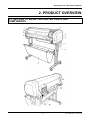
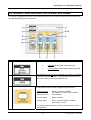
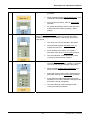
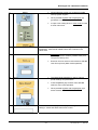

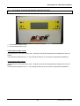

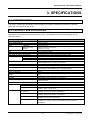

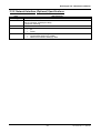

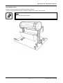


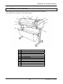

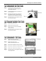
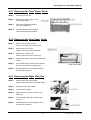
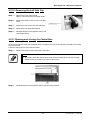

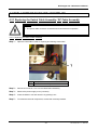

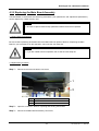
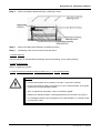
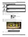
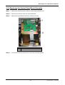
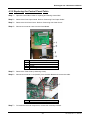
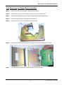
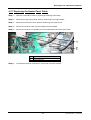

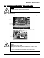
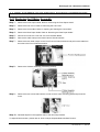


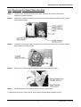
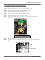

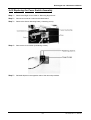


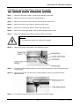

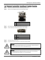
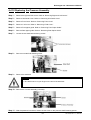
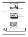
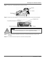
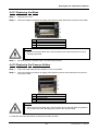


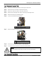


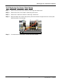
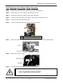
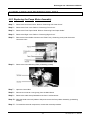
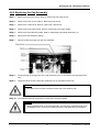
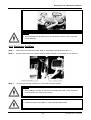
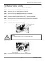

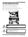

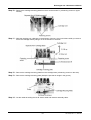
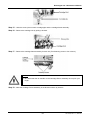

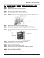


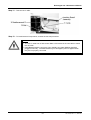
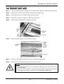
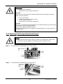

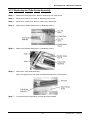
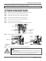


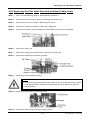
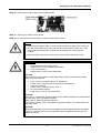


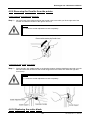

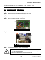

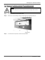
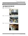

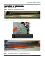

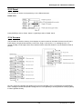

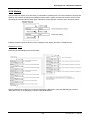
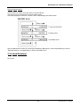
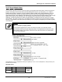
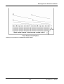
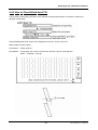
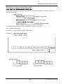

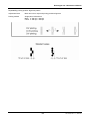
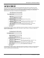
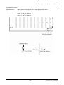
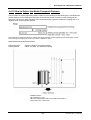

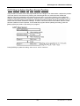


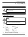


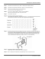

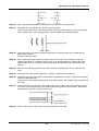
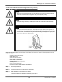

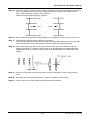

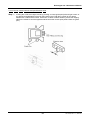
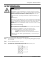


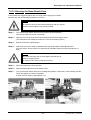
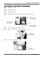


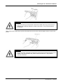


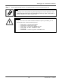

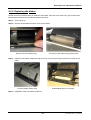


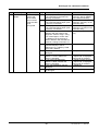
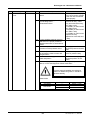


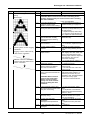


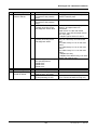
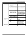
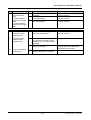
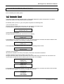


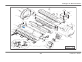


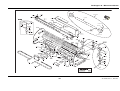
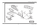

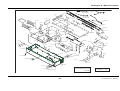


![Automa--o Industrial - Livro[1]](http://vs1.manualzilla.com/store/data/006090902_1-794daa7054a7431045e0dc6458174dc2-150x150.png)