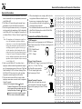
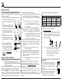
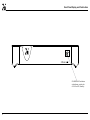
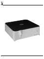
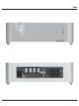
1
Wadia Digital, LLC. 2 Chambers Street Binghamton, New York 13903-2699
a315 power amplifier
Owner’s Manual
Phone: 607-723-3539 Fax: 607-724-0549 www.wadia.com
The lightning flash with arrowhead, within an equilateral
triangle, is intended to alert the user to the presence of
uninsulated “dangerous voltage” within the product’s enclosure that may be of sufficient magnitude to constitute
a risk of electric shock to persons.
WARNING - TO REDUCE RISK
OF FIRE OR ELECTRICAL
SHOCK, DO NOT EXPOSE
THIS EQUIPMENT TO RAIN OR
MOISTURE.
IMPORTANT SAFETY
INSTRUCTIONS!
PLEASE READ THEM BEFORE
OPERATING THIS EQUIPMENT.
1. Read these instructions.
2. Keep these instructions.
3. Heed all warnings.
4. Follow all instructions.
5. Do not use this apparatus near water.
6. Clean only with a dry cloth.
7. Do not block any ventilation openings. Install in
accordance with the manufacturer’s instructions.
8. Do not install near any heat sources such as radiators, heat registers, stoves, or other apparatus
(including amplifiers) that produce heat.
9. Do not defeat the safety purpose of the polarized
or grounding-type plug. A polarized plug has two
blades with one wider than the other. A grounding type plug has two blades and a third grounding prong. The wide blade or the third prong are
provided for your safety. If the provided plug does
2
The exclamation point within an equilateral triangle is
intended to alert the user to the presence of important
operating and maintenance (servicing) instructions in the
literature accompanying the appliance.
NO USER-SERVICEABLE PARTS
INSIDE. REFER SERVICING TO
QUALIFIED PERSONNEL.
not fit into your outlet, consult an electrician for
replacement of the obsolete outlet.
10. Protect the power cord from being walked on or
pinched particularly at plugs, convenience receptacles, and the point where they exit from the
apparatus.
11. Only use attachments/accessories specified by the
manufacturer.
12. Use only with the cart, stand, tripod, bracket, or
table specified by the manufacturer,
or sold with the apparatus. When a
cart is used, use caution when moving the cart/apparatus combination
to avoid injury from tip-over.
13. Unplug this apparatus during lightning storms or when unused for long periods of
time.
14. Refer all servicing to qualified service personnel.
Servicing is required when the apparatus has been
damaged in any way, such as power-supply cord
or plug is damaged, liquid has been spilled or
objects have fallen into the apparatus, the apparatus has been exposed to rain or moisture, does not
operate normally, or has been dropped.
15. Do not expose this equipment to dripping or
To prevent the risk of electric
shock, do not remove cover or
back. No user-serviceable parts
inside.
splashing and ensure that no objects filled with liquids, such as vases, are placed on the equipment.
16. To completely disconnect this equipment from the
a.c. mains, disconnect the power supply cord plug
from the a.c. receptacle.
17. The mains plug of the power supply cord shall
remain readily operable.
18. Do not expose batteries to excessive heat such as
sunshine, fire or the like.
19. Connect mains power supply cord only to a mains
socket outlet with a protective earthing connection.
Thank You
All of us at Wadia Digital would like to say thank you,
and congratulations for deciding to own this Wadia
a315 power amplifier. We sincerely believe this Wadia
product will bring you many years of musical enjoyment and satisfaction.
Please take a short time to read the information in this
manual. We want you to be as familiar as possible
with all the features and functions of your new Wadia
Product.
About Wadia ....
Wadia Digital, founded in 1988, is one of the
original companies dedicated to high performance
digital audio reproduction. Wadia is based on the
philosophy of applying advanced technology to
improve the performance of digital audio components.
Wadia has consistently raised the standard for
performance of Digital Audio playback. Some of
the technological innovations pioneered by Wadia
include:
• DigiMaster™ patented algorithm (filter optimized for reproducing music)
• ClockLink™ proprietary jitter reduction technology
• SwiftCurrent™ current to voltage conversion
technology
• First outboard Digital-to-Analog converter
• First to apply glass fiber-optics to home audio
Our designs are born of a delicate balance of
technology shaped by a passion for music. Wadia
continues to re-define the limits of digital music
playback.
Please Take A Moment
The serial number, purchase date and Wadia Dealer
name are important to you for possible insurance
claim or future service. The spaces below have been
provided for you to record that information:
Serial Number:________________________________
Purchase Date:________________________________
Dealer Name:_________________________________
Technical Assistance
If at any time you have questions about your Wadia
product, contact your Wadia Dealer who is familiar
with your Wadia equipment and any other brands that
may be part of your system. If you or your Dealer
wish additional help concerning a suspected problem,
you can receive technical assistance for all Wadia
products at:
Wadia Digital, LLC.
2 Chambers Street
Binghamton, New York 13903
Phone: 607-723-3539
Fax: 607-724-0549
Table of Contents
Safety Instructions.......................................................2
Thank You and About Wadia.......................................3
Please Take a Moment.................................................3
Technical Assistance and Customer Service...............3
Table of Contents.........................................................3
General Information....................................................4
Connector and Cable Information...............................4
Introduction..................................................................5
Performance Features..................................................5
Dimensions..................................................................6
Installation...................................................................7
Rear Panel Connections and Switch............................8
Output Terminals and How to Connect................ 10-11
Output Terminals and How to Connect
for Bi-Amp......................................................... 12-13
Front Panel Display and Push-Button........................ 14
How to Operate.......................................................... 15
Photos.................................................................... 16-17
Specifications............................................................. 18
Packing Instruction.................................................... 19
Customer Service
If it is determined that your Wadia product is in need
of repair, you can return it to your Dealer. You can
also return it to the Wadia Service Department. For
assistance on factory repair return procedure, contact
the Wadia Service Department at:
Wadia Digital, LLC.
2 Chambers Street
Binghamton, New York 13903
Phone: 607-723-3539
Fax: 607-724-0549
Copyright 2014 © by Wadia Digital, LLC.
3
General Information and Connector Information
General Information
1. For additional connection information, refer to the
owner’s manual(s) for any component(s) connected
to the Wadia a315.
2. The Wadia a315 mutes the speaker output for approximately two seconds when first turned on.
3. For the best performance and safety it is important
to always match the impedance of the Loudspeaker
to the Wadia a315 Power Amplifier Connections (4
or 8 ohms). Refer to “How to Connect” pages 8 thru
11.
Note: The impedance of a Loudspeaker actually varies as the Loudspeaker reproduces different
frequencies. As a result, the nominal impedance
rating of the Loudspeaker (usually measured at
a midrange frequency) might not always agree
with the impedance of the Loudspeaker at low
frequencies where the greatest amount of power
is required. Contact the Loudspeaker Manufacturer for additional information about the actual
impedance of the Loudspeaker before connecting
it to the Wadia a315.
4. In the event the Wadia a315 over heats, due to
improper ventilation and/or high ambient temperature, the protection circuits will activate. The Front
Panel Standby/ON LED will start flashing. When
the Wadia a315 has returned to a safe operating
temperature, normal operation will resume.
5. The protection circuits will also activate when
improper connections are made to the Loudpeaker
Output Terminals.
Caution: The Loudspeaker Output - Negative
Terminal Connections are not connected to
chassis ground. Do not combine any of the
Loudspeaker Ouput Terimals ( + Positive or
- Negative) connections together, ground
them or connect with another amplifier.
4
6. When discarding the unit, comply with local rules
or regulations. Batteries should never be
thrown away or incinerated but disposed
of in accordance with the local regulations
concerning battery disposal.
7. For additional information on the Wadia a315 and
other Wadia Products please visit the Wadia Web
Site at www.wadia.com.
Connector and Cable Information
XLR Connectors
Below is the Pin configuration for the XLR Balanced
Input Connectors on the a315. Refer to the diagram for
connections:
PIN 1: Shield/Ground
PIN 2: + Output
PIN 3: - Output
PIN 2
PIN 1
PIN 3
Trigger Control Connector
The Wadia a315 Trigger In receives an On/Off signal
from +5 to +12 volts. The TrigTrigger
ger Out will in turn provide a
Control
+12 volt Output Signal with a
N/C
total current up to 50mA.
Ground
Output Terminal Connector
When cables with spade lugs are used
for Loudspeaker Connection, the spade
lugs need an opening of at least 3/10 inch
(7.6mm).
3/10 of an inch
(7.6millimeters)
Introduction and Performance Features
Introduction
The Wadia 315 Power Amplifier is one of the finest
Digital Power Amplifiers available today. The 150
watts output per channel will drive any high quality Loudspeaker. The a315 reproduction is sonically
transparent and absolutely accurate.
• Custom Binding Posts
Patented gold plated output terminals deliver high
current output. They accept large diameter wire and
spade lugs. Banana plugs may also be used only in the
United States and Canada.
Performance Features
• LED Front Panel Indicator
A long life Light Emitting Diodes (LED) are used to
indicate the operational status of the a315.
• Adaptive Modulation Circuitry
Provides full power output over a wide frequency
response range with low distortion.
• Balanced and Unbalanced Inputs
Balanced connections allow long cable runs without
compromising sound quality.
• Amplifier and Loudspeaker Protection
Built-in Thermal Protection Circuit guards against
overheating. The Protection Circuit also actives if
Direct Current is detected at the Output Terminals.
• Die Cast Aluminium Chassis
Maintains cool operating temperatures of the internal
circuitry by the heat dissipating properties of the die
cast aluminium chassis. The aluminium chassis with
illuminated top glass panel is very durable and will
retained its appearance for many years to come.
• Power Supply
The a315 Power Amplifier has several regulated power
supplies, each one extremely stable to ensure noise
free operation even though the power line varies.
• Trigger Input and Output Connections
The Trigger Input and Output connection provides
convenient Turn-On/Off of additional Power Amplifiers and/or Source Components.
• Gold Plated Connectors
The Input and Output Connector Contacts are gold
plated for superior corrosion resistance and high electrical conductivity.
5
Dimensions
Dimensions
The following dimensions can assist in determining
the best location for your a315. There is additional
information on the next page pertaining to installing
the a315 into cabinets.
Front View of the a315
17-7/8"
45.4cm
2-7/8"
7.3cm
3-3/8"
8.6cm
Side View of the a315
19-1/8"
17-7/8"
45.4cm
Rear View of the a315
17-7/8"
45.4cm
16-7/16"
41.8cm
6
16-7/16"
41.8cm
48.6cm
Installation
Installation
The a315 is designed to be placed upright on a table
or shelf, standing on its feet. The ventilation requirements are shown.
Always provide adequate ventilation for your a315.
Cool operation ensures the longest possible operating life for any electronic instrument. Do not install
the a315 directly above a heat generating device, such
as another Power Amplifier. Allow at least 6 inches
(15.2cm) above the top, 5/8 inches (1.6cm) below the
bottom and 2 inch (5.1cm) on each side of the a315,
so that airflow is not obstructed. Allow 20 inches
(50.8cm) of depth for airflow and cable connections.
6"
15.2cm
a315 Front View
2"
2"
5.1cm
5.1cm
6"
15.2cm
a315 Side View
21-1/2"
54.6cm
7
Rear Panel Connections
LEFT OUTPUT Connections for
a 4 ohm or 8 ohm Loudspeaker
RIGHT OUTPUT Connections for
a 4 ohm or 8 ohm Loudspeaker
TRIGGER IN receives turn On/Off
signals from an audio component
TRIGGER OUT sends turn On/Off
signals to the next audio Component
INPUT MODE switch selects
between UNBALanced or
BALanced Input
UNBALanced INPUTS
for an audio cable from a
Preamplifier audio output
3
AUTO OFF Power Save
Feature is either DISabled
or ENAbled
Connect the Wadia a315 power
cord to a live AC outlet
BALanced INPUTS for audio cables
from a Preamplifier audio output
Caution: The Loudspeaker Output - Negative Terminal Connections are not connected to chassis ground. Do not combine any of the Loudspeaker Ouput Terimals
( + Positive or - Negative) connections together, ground them or connect with another amplifier.
8
9
Output Terminals
When connecting the Loudspeaker Hookup Cables
to the a315 Power Amplifier Output Terminals please
follow the steps below:
1. Rotate the top of the Output Terminal Post counterclockwise until an opening
appears. Refer to figures A and
B.
2. Insert the Loudspeaker hookup
Opening
cable into the Output Terminal
Figure
B
Figure
A
Post opening or the cable spade
lug around the center post of
the Output Terminal. Refer to
figure C.
3. Rotate the top of the Output
Terminal Post clockwise until
it is finger tight. Refer to figure
Figure C Figure D
D.
4. Place the supplied Wadia
Wrench over the top of the
Output Terminal and rotate it
one quarter of a turn (90°) to
secure the Loudspeaker Cable
Figure E
Connection. Do not over
tighten. Refer to figure E.
How to Connect
Caution: Do not connect the AC Power Cord to the a315
Rear Panel until after the Loudspeaker Connections are made. Failure to observe this could
result in Electric Shock.
The connection instructions below, together with the
a315 Connection Diagram located on the separate
folded sheet “ 1A”, is an example of a typical audio
system. Your system may vary from this, however the
actual components would be connected in a similar
10
manner. For additional information refer to “Connector and Cable Information” on page 4.
1. For remote AC Power Control of the a315, connect
a control cable from the Audio Preamplifier or
Source Device Trigger Out to the a315 TRIGGER
IN.
Note: When a Trigger Control Cable is connected
between the a315 and Preamplifier/Source
Device, the AUTO OFF Feature is bypassed.
Refer to page 15.
2. Connect XLR cables from the Balanced Output
(L&R) of an Audio Preamplifier/Source Device to
the a315 BALanced INPUTS (Right and Left).
Note: An optional hookup is to use unbalanced
cable and place the INPUT MODE Switch in
the UNBALanced Position.
This Wadia a315 Power Amplifier is designed for
Loudspeakers with an impedance of 4 ohms or 8
ohms. Connect a single Loudspeaker only to the Right
and Left Output Terminals.
When connecting Loudspeakers to the a315 it is
very important to use cables of adequate size, so there
is little to no power loss in the cables. The size is
specified in Gauge Numbers or AWG (American Wire
Gauge). The smaller the Gauge number, the larger the
wire size:
Loudspeaker Cable Distance vs Wire Gauge Guide
Loudspeaker
Impedance
25 feet
(7.62 meters)
or less
50 feet
(15.24 meters)
or less
100 feet
(30.48 meters)
or less
4 Ohms
14AWG
12AWG
10AWG
8 Ohms
16AWG
14AWG
12AWG
3. Prepare the Loudspeaker Hookup Cable for attachment to the a315 Power Amplifier:
Bare wire cable ends:
Carefully remove sufficient insulation from the
cable ends, refer to figures 2, 3 & 4. If the cable
is stranded, carefully twist the strands together
as tightly as possible.
Figure 2
Figure 3
Figure 4
Notes: 1. If desired, the twisted ends can be tinned
with solder to keep the strands together.
2. The prepared bare wire cable ends may be
inserted into spade lug connectors.
3. Banana plugs are for use in the United
States and Canada only.
Banana Plugs are for use in the United States and
Canada only:
4. Attach the previously prepared bare wire cable ends
into the banana plugs and secure the
connections. Refer to figure F.
5. Rotate the top of the Output Terminal
Post clockwise until it is finger tight.
Figure F
Refer to figure G. Then using the
Wadia Wrench, rotate the top of the
Output Terminal one quarter of a turn
(90°). Do not over tighten. Refer to
Figure G
figure E.
6. Referring to figure H, connect the Loudspeaker hookup
cables with banana plugs into
the hole at the end of the a315
Figure H
Negative and Positive Output
Terminals, being careful to observe the correct
polarities.
Refer to “General Information” Note 3 on page 4 for
additional information.
Output Terminals and How to Connect
WARNING: Loudspeaker terminals are hazardous
live and present a risk of electric shock.
For additional instruction on making Loudspeaker Connections contact
your Wadia Dealer or Wadia Technical
Support.
7. Connect the a315 Power Cord to an active AC
outlet.
Spade Lug or Wire Connections:
8. Connect the Loudspeaker hookup cables to the
a315 Negative Output Terminal and Positive
Output Terminal, being careful to observe the correct polarities. Insert the spade lug connector or
prepared section of the cable end into the terminal
side access hole, and tighten the terminal cap until
the cable is firmly clamped into the terminals so
the lugs or wire cannot slip out. Refer to figures 5
and 6.
Figure 5
Figure 6
Refer to “General Information” Note 3 on page 4 for
additional information.
WARNING: Loudspeaker terminals are hazardous live and present a risk of electric
shock. For additional instruction on
making Loudspeaker Connections
contact your Wadia Dealer or Wadia
Technical Support.
9. Connect the a315 Power Cord to an active AC
outlet.
11
Output Terminals
When connecting the Loudspeaker Hookup Cables
to the a315 Power Amplifier Output Terminals please
follow the steps below:
1. Rotate the top of the Output Terminal Post counterclockwise until an opening
appears. Refer to figures A and
B.
2. Insert the Loudspeaker hookup
Opening
cable into the Output Terminal
Figure
B
Post opening or the cable spade Figure A
lug around the center post of
the Output Terminal. Refer to
figure C.
3. Rotate the top of the Output
Terminal Post clockwise until
it is finger tight. Refer to figure
Figure C Figure D
D.
4. Place the supplied Wadia
Wrench over the top of the
Output Terminal and rotate it
one quarter of a turn (90°) to
secure the Loudspeaker Cable
Figure E
Connection. Do not over
tighten. Refer to figure E.
How to Connect for Bi-Amp
Caution: Do not connect the AC Power Cord to the a315
Rear Panel until after the Loudspeaker Connections are made. Failure to observe this could
result in Electric Shock.
The connection instructions below, together with the
a315 Connection Diagram located on the separate
folded sheet “ 1B”, is an example of a typical audio
system. Your system may vary from this, however the
actual components would be connected in a similar
manner. For additional information refer to “Connec12
tor and Cable Information” on page 4.
1. For remote AC Power control of the a315, connect
a control cable from the Audio Preamplifier or
Source Device Trigger Out to the a315 TRIGGER
IN.
Note: When a Trigger Control Cable is connected
between the a315 and Preamplifier/Source
Device, the AUTO OFF Feature is bypassed.
Refer to page 15.
2. Connect a control cable from the Amplifier One
TRIGGER OUT to Amplifier Two TRIGGER IN.
Note: There is approximately a one-half second delay added to the TRIGGER OUT signal in a315
Power Amplifier to reduce the strain on the AC
Power Line. This will delay the Turn-On of the
second a315 Power Amplifier.
3. Connect audio cables from the Unbalanced Output
(L&R) of an Audio Preamplifier/Source Device to
the amplifier one UNBALanced INPUTS (Right
and Left).
Note: Place the INPUT MODE Switch to the UNBALanced position.
4. Connect balanced XLR cables from the Balanced
Output (L&R) of an Audio Preamplifier/Source
Device to the amplifier two BALanced INPUTS
(Right and Left).
Note: Place the INPUT MODE Switch to the BALanced position.
The Wadia a315 Power Amplifier is designed for
Loudspeakers with an impedance of 4 ohms or 8
ohms. Connect a single Loudspeaker only to the Output Terminals.
When connecting Loudspeakers to the a315 it is
very important to use cables of adequate size, so there
is little to no power loss in the cables. The size is
specified in Gauge Numbers or AWG (American Wire
Gauge).
The smaller the Gauge number, the larger the wire
size:
Loudspeaker Cable Distance vs Wire Gauge Guide
25 feet
(7.62 meters)
or less
50 feet
(15.24 meters)
or less
4 Ohms
14AWG
12AWG
10AWG
8 Ohms
16AWG
14AWG
12AWG
Loudspeaker
Impedance
100 feet
(30.48 meters)
or less
5. Prepare the Loudspeaker Hookup Cable for attachment to the a315 Power Amplifier:
Bare wire cable ends:
Carefully remove sufficient insulation from the
cable ends, refer to figures 2, 3 & 4. If the cable
is stranded, carefully twist the strands together
as tightly as possible.
Figure 2
Figure 3
Figure 4
Notes: 1. If desired, the twisted ends can be tinned
with solder to keep the strands together.
2. The prepared bare wire cable ends may be
inserted into spade lug connectors.
3. Banana plugs are for use in the United
States and Canada only.
Banana Plugs are for use in the United States and
Canada only:
6. Attach the previously prepared bare
wire cable ends into the banana plugs
and secure the connections. Refer to
Figure F
figure F.
7. Rotate the top of the Output Terminal
Post clockwise until it is finger tight.
Refer to figure G. Then using the
Figure G
Wadia Wrench, rotate the top of the
How to Connect for Bi-Amp
Output Terminal one quarter of a turn (90°). Do not
over tighten. Refer to figure E.
8. Referring to figure H, connect the Loudspeaker
hookup cables with banana
plugs into the hole at the end
of the a315 Negative and Positive Output Terminals, being
Figure H
careful to observe the correct
polarities.
Refer to “General Information” Note 3 on page 4 for
additional information.
Refer to “General Information” Note 3 on page 4 for
additional information.
WARNING: Loudspeaker terminals are hazardous live and present a risk of electric
shock. For additional instruction on
making Loudspeaker Connections
contact your Wadia Dealer or Wadia
Technical Support.
11. Connect the a315 Power Cord to an active AC
outlet.
WARNING: Loudspeaker terminals are hazardous
live and present a risk of electric shock.
For additional instruction on making Loudspeaker Connections contact
your Wadia Dealer or Wadia Technical
Support.
9. Connect the a315 Power Cord to an active AC
outlet.
Spade Lug or Wire Connections:
10. Connect the Loudspeaker hookup cables to the
a315 Negative Output Terminal and Positive
Output Terminal, being careful to observe the correct polarities. Insert the spade lug connector or
prepared section of the cable end into the terminal
side access hole, and tighten the terminal cap until
the cable is firmly clamped into the terminals so
the lugs or wire cannot slip out. Refer to figures 5
and 6.
Figure 5
Figure 6
13
Front Panel Display and Push-button
STANDBY/ON Push-button
with indicator, switches the
a315 ON or OFF (Standby)
14
How to Operate
How to Operate
Power On/Off
Momentarily press the POWER Push-button to switch
the a315 On or Off. Refer to figure 7.
3
Note: There must be a Trigger Control
Connection between the a315 and
the Audio Preamplifier or Source
Device, in order for the remote
power turn-on to function.
Input Mode Switch
The Input Mode Switch, which is located on the Rear
Panel of the a315, allows selection of
either the BALanced or UNBALanced
Figure 9
Inputs. Refer to figure 9.
Figure 7
Auto Off
The a315 incorporates a Power Save Feature to
automatically switch power Off to the Power Amplifier approximately 30 minutes after there has been an
absence of an audio input signal.
Note: If the Power Save Feature has activated and
switched the a315 Off, the Power Save Feature can be reset by momentarily pressing the
STANDBY/ON Push-button.
When there is a Trigger Input Connection between
the a315 and a Preamplifier or Source Device, the
Power Save Feature in the a315 is bypassed.
With the a315 connected (via Trigger Control) to
a Preamplifier (Source Device) with the Power Save
Feature and the feature is active, the a315 will switch
Off with the Preamplifier (Source Device) after a
period of inactivity.
There may be times when it would be desirable to
bypass the Power Save Feature, which by default is active. This can be implemented by placing the “AUTO
OFF” Switch, located on the a315 Rear
Panel, in the DIS (Disable) position.
Figure 8
Refer to figure 8:
15
16
Photos
17
Specifications
Specifications
Power Output
Minimum sine wave continuous average power output
per channel, with both channels operating at 0.5%
Total Harmonic Distortion is:
150 watts into 8 ohm load
250 watts into 4 ohm load
Output Load Impedance
8 or 4 ohms
Rated Power Band
20Hz to 20,000Hz
General Specifications
Signal To Noise Ratio (A-Weighted)
90dB (112dB below rated output) Balanced
88dB (110dB below rated output) Unbalanced
Intermodulation Distortion
0.1% maximum if the instantaneous peak power
output does not exceed the rated power output, for any
combination of frequencies from 20Hz to 20,000Hz.
Wide Band Damping Factor
Greater than 320, 8 Ohm load
Greater than 160, 4 Ohm load
Total Harmonic Distortion
0.1% maximum harmonic distortion at any level from
250 milliwatts to one-half of rated power output, 20Hz
to 20,000Hz.
0.5% maximum harmonic distortion at any level from
one-half to full rated power output, 20Hz to 20,000Hz.
Input Impedance
10,000 ohms Balanced
10,000 ohms Unbalanced
Dynamic Headroom
1dB, 8 ohm load
1.6dB, 4 ohm load
Trigger Input
5-15VDC, less than 1mA
Frequency Response
+0, -0.5dB from 20Hz to 20,000Hz
+0, -3.0dB from 10Hz to 70,000Hz
Input Sensitivity (for rated output)
2.4 Volts Balanced
1.2 Volts Unbalanced
18
Voltage Gain
29dB
Trigger Output
12VDC, 50mA maximum
Output is delayed 0.2 seconds from turn On
Power Requirement
100V - 240V ~ 50/60Hz at 130 Watts
Standby: less than 0.5 watt
Note: All Specifications are with AC Line voltage of
120V.
Overall Dimensions
Width is 17-7/8 inches (45.4cm)
Height is 3-3/8 inches (8.6cm) including feet
Depth is 20 inches (50.8cm) including the Cables
Weight
27 pounds (12.2 kg) net, 31.5 pounds (14.3 kg) in shipping carton
Shipping Carton Dimensions
Width is 22-1/2 inches (57.2cm)
Height is 8-1/8 inches (20.6cm)
Depth is 22-1/2 inches (57.2cm)
Packing Instructions
Packing Instructions
In the event it is necessary to repack the equipment for
shipment, the equipment must be packed exactly as
shown below. It is very important to ensure the proper
equipment location between the bottom and top foam
pads. Failure to do this will result in shipping damage.
Use the original shipping carton and interior parts
only if they are all in good serviceable condition. If
a shipping carton or any of the interior part(s) are
needed, please call or write Customer Service Department of Wadia. Refer to page 4. Please see the Part
List for the correct part numbers.
Quantity
1
Part Number
034555
Description
Shipping carton only
034556
034564
Top foam pad
Bottom foam pad
1
1
TOP FOAM PAD
OWNER’S
MANUAL
UNIT
AC POWER CORD
BOTTOM FOAM PAD
SHIPPING CARTON
19
Wadia Digital, LLC
2 Chambers Street
Binghamton, NY 13903
www.wadia.com
The continuous improvement of its products is
the policy of Wadia Digital who reserve the right
to improve design without notice. Printed in the
U.S.A.
Wadia Digital Part No. 04152100