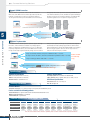
1
Industrial I/O
Product Selection Guides
Stand-alone Type I/Os . . . . . . . . . . . . . . . . . . . . . . . . . . . . . . . . . . . . . . . . . . . . . . . . . . . . .5-2
Modular Type I/Os . . . . . . . . . . . . . . . . . . . . . . . . . . . . . . . . . . . . . . . . . . . . . . . . . . . . . . 5-2
Industrial I/O
Introduction to Industrial I/O . . . . . . . . . . . . . . . . . . . . . . . . . . . . . . . . . . . . . . . . . . . . . . 5-3
I/O Software Solutions
Active OPC Server Lite Seamlessly connect ioLogik to your SCADA system . . . . . . . . .5-11
Click&Go Easy and intuitive I/O control configuration for the ioLogik Active Ethernet I/O
. . . . . . . . . . . . . . . . . . . . . . . . . . . . . . . . . . . . . . . . . . . . . . . . . . . . . . . . . . . . . . . . . . . . . . . . .5-13
Active Ethernet I/O
ioLogik E2210 Active Ethernet I/O with 12 DIs and 8 DOs . . . . . . . . . . . . . . . . . . . . . . . .5-15
ioLogik E2212 Active Ethernet I/O with 8 DIs, 8 DOs, and 4 configurable DIOs . . . . . . .5-16
ioLogik E2214 Active Ethernet I/O with 6 DIs and 6 relay outputs . . . . . . . . . . . . . . . . .5-17
ioLogik E2240 Active Ethernet I/O with 8 AIs and 2 AOs . . . . . . . . . . . . . . . . . . . . . . . . .5-18
ioLogik E2242 Active Ethernet I/O with 4 AIs and 12 configurable DIOs . . . . . . . . . . . .5-19
ioLogik E2260 Active Ethernet I/O with 6 RTD inputs and 4 DOs . . . . . . . . . . . . . . . . . .5-20
ioLogik E2262 Active Ethernet I/O with 8 thermocouple inputs and 4 DOs . . . . . . . . . .5-21
Peer-to-Peer I/O
ioMirror E3210 Ethernet Peer-to-Peer I/O with 8 DIs and 8 DOs . . . . . . . . . . . . . . . . . . .5-22
Modular Active Ethernet I/O
ioLogik E4200 Modular Active Ethernet I/O adaptor . . . . . . . . . . . . . . . . . . . . . . . . . . . . .5-24
NA-4010 Ethernet network adaptor . . . . . . . . . . . . . . . . . . . . . . . . . . . . . . . . . . . . . . . . . .5-25
Management Accessories
LDP1602 LCD Module Snap-on module for ioLogik 2000 and ioMirror 3000 . . . . . . . .5-26
Cellular GPRS I/O
ioLogik W5340 Active GPRS I/O with 4 AIs, 8 DIOs, and 2 relay outputs . . . . . . . . . . . .5-27
RS-485 I/O
ioLogik R2110 RS-485 remote I/O with 12 DIs and 8 DOs . . . . . . . . . . . . . . . . . . . . . . .5-29
ioLogik R2140 RS-485 remote I/O with 8 AIs and 2 AOs. . . . . . . . . . . . . . . . . . . . . . . . .5-30
Modular Serial I/O
NA-4020/4021 RS-485 or RS-232 network adaptors . . . . . . . . . . . . . . . . . . . . . . . . . . .5-31
Digital Input Modules
Digital Output Modules
. . . . . . . . . . . . . . . . . . . . . . . . . . . . . . . . . . . . . . . . . . . . . . . . . . . .5-33
. . . . . . . . . . . . . . . . . . . . . . . . . . . . . . . . . . . . . . . . . . . . . . . . . . .5-35
Analog Input Modules . . . . . . . . . . . . . . . . . . . . . . . . . . . . . . . . . . . . . . . . . . . . . . . . . . . .5-37
Temperature Input Modules
Analog Output Modules
Power Modules
. . . . . . . . . . . . . . . . . . . . . . . . . . . . . . . . . . . . . . . . . . . . . . .5-38
. . . . . . . . . . . . . . . . . . . . . . . . . . . . . . . . . . . . . . . . . . . . . . . . . .5-39
. . . . . . . . . . . . . . . . . . . . . . . . . . . . . . . . . . . . . . . . . . . . . . . . . . . . . . . . .5-40
Modular I/O Accessories
. . . . . . . . . . . . . . . . . . . . . . . . . . . . . . . . . . . . . . . . . . . . . . . . .5-42
5
Industrial I/O
Remote Monitoring Solutions
Stand-alone Type I/Os
5
Industrial I/O > Product Selection Guides
Model
ioLogik W5340
ioLogik E2210
ioLogik E2212
ioLogik E2214
ioLogik E2240
ioLogik E2242
Category
Cellular GPRS I/O
Active Ethernet I/O
Active Ethernet I/O
Active Ethernet I/O
Active Ethernet I/O
Active Ethernet I/O
Comm.
Interface
I/O
Combination
Control
Protocol
GPRS, 10/100M
Ethernet
10/100M Ethernet
10/100M Ethernet
10/100M Ethernet
10/100M Ethernet
10/100M Ethernet
4 AIs, 8 DIOs,
2 Relays
12 DIs, 8 DOs
8 DIs, 8 DOs, 4 DIOs
6 DIs, 6 Relays
8 AIs, 2 AOs
4 AIs, 12 DIOs
Modbus/TCP, SNMP,
OPC
Modbus/TCP, SNMP,
OPC, Http-CGI
Modbus/TCP, SNMP,
OPC, Http-CGI
Modbus/TCP, SNMP,
OPC, Http-CGI
Modbus/TCP, SNMP,
OPC, Http-CGI
Modbus/TCP, SNMP,
OPC, Http-CGI
Local
Intelligence
Click&Go
Click&Go
Click&Go
Click&Go
Click&Go
Click&Go
Alarm
Function
SMS, E-mail, SNMP
Traps, TCP/UDP
Messaging
E-mail, SNMP Traps,
TCP/UDP Messaging
E-mail, SNMP Traps,
TCP/UDP Messaging
E-mail, SNMP Traps,
TCP/UDP Messaging
E-mail, SNMP Traps,
TCP/UDP Messaging
E-mail, SNMP Traps,
TCP/UDP Messaging
Model
Category
Comm.
Interface
I/O
Combination
Control.
Protocol
ioLogik E2260
ioLogik E2262
ioLogik R2110
ioLogik R2140
ioMirror E3210
Active Ethernet I/O
Active Ethernet I/O
RS-485 I/O
RS-485 I/O
Peer-to-Peer I/O
10/100M Ethernet
10/100M Ethernet
RS-485
RS-485
10/100M Ethernet
4 DOs, 6 RTDs
4 DOs, 8 TCs
12 DIs, 8 DOs
8 AIs, 2 AOs
8 DIs, 8 DOs
Modbus/TCP, SNMP, OPC,
Http-CGI
Modbus/TCP, SNMP, OPC,
Http-CGI
Modbus/RTU
Modbus/RTU
---
Local
Intelligence
Click&Go
Click&Go
---
---
---
Alarm
Function
E-mail, SNMP Traps,
TCP/UDP Messaging
E-mail, SNMP Traps,
TCP/UDP Messaging
---
---
Alarm Channel with LED
for Conn. Status
Modular Type I/Os
Model
Category
Comm.
Interface
Max.
Expansion
Capacity
Control
Protocol
5-2
ioLogik E4200
NA-4010
NA-4020
NA-4021
Modular Active Ethernet I/O
Modular Ethernet I/O
Modular Serial I/O
Modular Serial I/O
Dual 10/100M Ethernet
10/100M Ethernet
RS-485
RS-232
16 slices
31 slices
31 slices
31 slices
Modbus/TCP, SNMP, OPC
Modbus/TCP
Modbus/RTU
Modbus/RTU
Local
Intelligence
Click&Go
---
---
---
Alarm
Function
SMS, E-mail, SNMP Traps,
TCP/UDP Messaging
---
---
---
SMS/GPRS
Connectivity
Yes, with an ext. modem
---
---
---
w w w. m o x a . c o m
[email protected]
Industrial Networking Solutions
Introduction to Industrial I/O
Intelligent, high-performance, reliable I/O modules for automation
5
Industrial I/O > Introduction to Industrial I/O
Moxa’s ioLogik series of industrial I/O products are intelligent, highperformance, reliable remote I/O solutions that bring the ease of
open-standard Ethernet/TCP and serial RS-232/485 communications
to automation applications, including data acquisition, and remote
monitoring and alarm systems. The ioLogik series also offers greater
flexibility by making it easy to install analog, digital, and temperature
measurement instruments on the same mounting rack. The ioLogik
industrial I/O series is ideal for both stand-alone and high-density
mounting on a rack, in a cabinet, or on a panel, and can be easily
adapted to industrial applications that require multiple I/O points.
/O
lI
[email protected]
ia
ioLogik R2000
RS-485 I/O
Et
he
rn
et
I/
O
Wireless I/O
r
Se
Moxa’s industrial I/O products can be divided into several categories,
which include Ethernet I/O, Wireless I/O, and Serial I/O. Features such
as built-in local intelligence (Click&Go) and a variety of form factors
provide a number of options that users can choose from. The Ethernet
I/O products, for example, can also be subdivided into Active Ethernet
IO (ioLogik E2000 series), Modular Active Ethernet I/O (ioLogik E4200
with its slice type modules), and Peer-to-peer I/O (ioMirror E3210).
Serial I/O can be subdivided into Stand-alone RS-485 I/O (ioLogik
R2000 series), and Modular I/O (ioLogik NA-4020/4021 network
adaptors with slice type modules). The Wireless I/O category currently
contains one product, the ioLogik W5340 GPRS I/O.
ioLogik W5300
Cellular GPRS I/O
ioLogik E2000
Active Ethernet I/O
ioLogik E4200
Modular Active
Ethernet I/O
ioLogik 4000
Serial Modular I/O
ioMirror E3210
Peer-to-Peer I/O
w w w. m o x a . c o m
5-3
Remote Monitoring Solutions
Active Ethernet I/O
The Most Intelligent I/O for Remote Monitoring and Alarm Applications
5
ioLogik also supports Active Ethernet I/O, which is a new concept
introduced by Moxa that offers proactive, condition-based reporting
and the control of I/O devices used for PC-based data acquisition
and control. The I/O status of an Active Ethernet I/O device can be
reported and controlled automatically on-site based on user specified
conditions. This report-by-exception approach, which is new to PCbased monitoring, requires far less bandwidth than traditional polling
methods. Critical sensor data can be obtained immediately instead
of being confined by the use of polling intervals. This makes network
communication between a host computer and Active Ethernet I/O
devices concise and efficient, and makes data transmission 20 times
faster compared with traditional SCADA systems (50 ms compared to
1 sec).
The intelligence of Active Ethernet I/O is integrated by two parts:
• The programming-free local control logic of Click&Go, and
• Remote I/O control
Click&Go provides a programming-free, easy-to-learn IF-THEN-ELSE
style of local I/O control that is capable of combining time-control
or delivering TCP/UDP/SNMP Trap/e-mail/SMS messages with time
stamp. In addition to Modbus/TCP, Active Ethernet I/O supports
the familiar SNMP and HTTP-CGI protocols, giving IT engineers
more options for obtaining remote I/O status and sending control
commands. In addition, the Active OPC Server package makes it easy
to link Active Ethernet I/O to SCADA systems.
Industrial I/O > Introduction to Industrial I/O
Why Choose Active Ethernet I/O?
IA and IT-friendly Remote I/O Control
Intelligent Local I/O Control
• Moxa’s Active OPC Server can connect an ioLogik to SCADA
systems
• Open-standard Modbus/TCP I/O control
• SNMP I/O control for IT-based network
management
• CGI command I/O control for surveillance systems
• MXIO Library for WinCE/Linux, C++,
VB/VC and .NET platforms
• IF-THEN-ELSE style programming with no learning curve
• PLC-grade I/O control, timer, schedule, and register functions
• No need for third-party development tools,, and no maintenance
gaps
• Stand-alone operations require
no host control
• Dramatic reduction in project
implementation time
Push Technology for Events and Alarms
Solution-oriented Design
• Event-based TCP/UDP messages, SNMP traps, e-mail, SMS, and
CGI command output
• Real-time events with time stamp
• Moxa’s Active OPC Server package
• Saves bandwidth with no polling effort
•
•
•
•
•
Easy-to-expand slice-type I/O modules
Intuitive Windows utility
Peer-to-peer function
Dual-LAN redundancy
Optional LCM module
IA and IT-friendly Approaches to Remote I/O Control
In addition to Modbus/TCP, the I/O status of an Active Ethernet I/O
device can be controlled in various ways. IT engineers can use SNMP
and CGI, whereas IA engineers can use open-standard Active OPC
Server. In addition, the MXIO library also offers programmers the
benefit of fast implementation.
5-4
w w w. m o x a . c o m
[email protected]
Industrial Networking Solutions
Push Technology for Events and Alarms
Active Messaging
TCP/UDP Message + Time Stamp
SNMP Trap + Time Stamp
DO-Stir Machine
hine
RTD1
RTD2
RTD3
DO Heater
e-mail + Time Stamp
39˚C
42˚C
45˚C
Active Ethernet I/O can be used to generate
alarms when an event (user-defined by Click&Go)
is triggered. Standard TCP or UDP packets can
be sent to a central host, SNMP traps can be
sent to IT monitoring systems, and e-mail/SMS
messages can be sent to the site maintainer.
SMS (Short Message) + Time Stamp
Active OPC Server Connection to SCADA
5
Industrial I/O > Introduction to Industrial I/O
Active OPC Server Lite is a free software package
provided by Moxa that operates as an OPC driver
for an HMI or SCADA system. Active OPC Server
Lite offers seamless connection from Moxa’s
ioLogik series products to SCADA systems with
7 times the normal response, 50 times faster tag
installation, and an 80% reduction of network
bandwidth usage compared with other traditional
OPC packages on the market.
Intelligent Local I/O Control
Local Alarm & I/O Control
Active Ethernet I/O can be used for simple output
control that is triggered by input status, without a
PC controller. For example, a door sensor can be
configured to trigger an alarm. Configuration is
done through intuitive If/Then statements, with no
programming required.
If DI_0=On, Then DO_0=On
Local intelligence
No programming
Instant Event Reporting by Input Status
Counter = 1
People Counter
Improves data acquisition and control system efficiency
More accurate and timely measurements to prevent data loss
[email protected]
Instead of relying on host computers that
continually poll I/O devices for data, Active
Ethernet I/O devices can proactively report
sensor status using TCP or UDP messages.
Proactive messaging allows much faster
notification of I/O events and generates much
lower network and CPU loads. Message content
is fully customizable, and up to 10 simultaneous
destinations are supported.
w w w. m o x a . c o m
5-5
Remote Monitoring Solutions
Solution-oriented Design
Dual-LAN Redundancy
Primary Host
LAN 1
LAN 2
5
Backup Host
Peer-to-Peer Communication over Ethernet
Industrial I/O > Introduction to Industrial I/O
Easy Expansion with Slice-type Modules
Slice Type I/O Modules
The ioMirror E3000 series of Ethernet I/O
products are designed as cable replacement
solutions that send input signals to remote
outputs over an IP network. ioMirror products
can be used to connect remote sensor signals to
PLC controllers, DCS systems, or display devices
over a network, without installing additional
signal wires.
The ioLogik 4000 provides spring type,
removable terminal blocks (RTBs) that allow you
to preserve field wiring before replacing an I/O
expansion module. Each I/O expansion module
can be replaced quickly and easily.
Spring Type Terminal Block
Intuitive Windows Utility
ioLogik remote I/O products come with a very
user-friendly Windows utility that includes
remote configuration, firmware updates, and
I/O testing and monitoring functions. These
functions can save you many hours of installation
and troubleshooting, and all settings can be
saved to a file for future reference.
Optional LCD Module
5-6
The ioLogik E4200 series of Modular Active
Ethernet I/O products come with dual network
interfaces, which have separate MACs and
IP addresses to connect to different network
segments. Redundancy can be easily
implemented to improve system reliability by
allowing hosts located on different networks to
control or monitor your system.
w w w. m o x a . c o m
The ioLogik 2000 series of stand-alone remote
I/O products provides an optional LCD module
for on-site management and configuration. The
unique display module can display network and
I/O settings. You can change network settings
to ensure the speed of installation and future
maintenance.
[email protected]
Industrial Networking Solutions
Wireless I/O
Integrating I/O and GPRS Communications
Active GPRS I/O is a highly integrated solution that combines GPRS communications, front-end intelligence, and a front-end data logging function
for information analysis and prediction. By using GPRS technology, the ioLogik W5000 series gives remote monitoring applications maximum
coverage. The W5000 series products come with one 3-in-1 serial port (RS-232/422/485) to connect field serial devices such as meters, analyzers, and
instruments. The ioLogik W5000 is a perfect fit for remote monitoring and alarm systems for which wired connections are difficult or impossible, such
as unmanned site monitoring, riverside monitoring, and pipeline monitoring.
Wider Co
Coverage
with GPRS telemetry
netw
network
Trouble-free
e
network
connections with
th
ver
er
Active OPC Server
ioLogik
Logik
g W5340
5340
with Click&Go
5
Data Logging
Da
Industrial I/O > Introduction to Industrial I/O
Friendly
serial device
connectivity
Front-end
Intelligence
st
store
data for
up to 14 days
Save Power
reduce expenses
Trouble-free Connections to GPRS Networks
Managing dynamic IP addresses for automation projects that require setting up connections to the GPRS network can be a big headache for engineers.
Thanks to Active GPRS I/O with Push Technology and Active OPC Server, dynamic IP addresses can be managed between the Active GPRS I/O product
and the Active OPC Server. In this case, SCADA programs can receive data from the Active OPC Server without putting additional effort into managing
IP addresses.
Most traditional solutions use DDNS or a purchased service package from an MVNO (Mobile Virtual Network Operator) to make IP management easier.
GPRS networks usually offer a dynamic IP environment with the IP address assigned by the cellular service provider, but it is difficult to poll a GPRS
device’s data in a dynamic IP environment. Even with DDNS technology, SCADA projects still need to allocate resources to manage the DDNS server.
Moxa’s Active OPC Server makes it easy to install an ioLogik W5000 in a GPRS dynamic IP environment, and since remote Active GPRS I/O
automatically establishes communication with Active OPC Server, all remote Active GPRS I/Os can be managed by one centralized Active OPC Server,
which itself has a fixed IP address. Active OPC Server receives and registers the ioLogik W5000’s IP address and receives tag updates, and application
programs can poll data via Active OPC Server without exerting any effort on IP management.
Front-End Intelligence for Handling Events
The Click&Go software package provides Active GPRS I/O with front-end intelligence for event response and alarms. When a pre-defined event is
triggered, a variety of alarms, such as SMS, email, TCP/UDP packets, and SNMP Trap, can be sent actively, and depending on the type of configuration
you’re using, real time stamps can also be attached.
Friendly Serial Device Connectivity
Active GPRS I/O devices are equipped with one 3-in-1 (RS-232/485/422) serial port. When GPRS is on line, the Active GPRS I/O device will establish
a TCP Client connection with the PC software, and then use this transparent data tunnel to poll or read remote meters. Thanks to the Active GPRS I/O
device’s TCP Client support, dynamic IP addresses are no longer a problem.
Data Logging—Store up to 14 Days of I/O Records
ioLogik Active GPRS I/O devices come with an external SD card slot
that can be used to store I/O status, with each day’s records stored in
a separate file. The files are stored in .CSV file format and use TFTP
protocol for exchanging files between the PC and Active GPRS I/O
device, making it easy for users to import the records into a database
and display in chart format.
[email protected]
w w w. m o x a . c o m
5-7
Remote Monitoring Solutions
The Benefits of Integration
ioLogik Active Wireless I/O provides an integrated solution with a
number of important benefits.
Easy to Install
Extra Power Savings
Caller ID for Security
Needs only a Sliver of Bandwidth
5
Easy Installation
Industrial I/O > Introduction to Industrial I/O
By supporting Moxa’s powerful Active OPC Server, Active GPRS I/O
products can be easily integrated with your SCADA system. Moxa’s
Active OPC Server with non-polling architecture supports the standard
OPC protocol, but also offers active (or “push”) communication
between Moxa’s ioLogik series of Active GPRS I/O products and HMI/
SCADA systems with instant I/O status.
Unlike the fixed IP requirement for Ethernet I/O with a traditional OPC
server, Active OPC Server and ioLogik products deliver the flexibility of
using dynamic IP addresses. The ioLogik product can connect directly
to the Active OPC Server instead of being polled, which makes the
dynamic IP configuration and WAN Access of the GPRS I/O possible.
As far as traditional data acquisition applications are concerned,
I/O devices are not capable of using this approach. In addition, the
flexibility of being able to connect through a firewall is a useful feature.
WAN
Dynamic IP Address
SCADA
Active OPC Server
ioLogik W5340
Push-based Active OPC Server
Active OPC Server and ioLogik series products offer “Auto Tag Generation” to eliminate the need to specify target IP addresses, I/O channels, and data
formats one by one or edit and import configuration text files. Instead, Active OPC Server creates the tags for the target ioLogik automatically. Simply
select the channels that need to be updated, and the tags are generated and configured without needing any input from the user. Generally speaking,
tag generation is 50 times faster on Active OPC Server than with traditional OPC server packages, and training on how to install and configure the OPC
server is no longer necessary.
Low Power Consumption and Sleep Mode
Due to the high integration of GPRS communication, I/O functions, and data-logging, the power consumption of
Moxa’s integrated solution is half that of using separate solutions. You will be able to build a system that uses a
smaller solar power panel and lower battery capacity. For example, the ioLogik W5340 provides the optimal solution
for riverside monitoring applications, such as monitoring water flow to prevent flood disasters, or monitoring water
quality to protect the supply of drinking water. This solution’s power saving feature requires less power, even when
the power is supplied by a solar panel or battery. It also provides a data logging function for keeping the necessary
data on an SD card, and you can receive active messages automatically when a pre-defined condition is triggered.
When sleep mode is activated, the ioLogik W5340 will turn off GPRS communications, but keep the I/O function
working, and the status of all I/O activity will be recorded in a data Log file. The data log function will create a
new file every day and can be configured to upload the latest data to a host every night at midnight. In addition to
ensuring that all data is sent to your analysis system, you can also extend your I/O operation while using backup
battery power.
5-8
w w w. m o x a . c o m
[email protected]
Industrial Networking Solutions
Secure Wake on Call
There are three ways to wake up an ioLogik Active GPRS I/O. The first is wake up by event, such as with an active message, SMS, email, or SNMP
Trap. The second is wake on call. In this case, the ioLogik W5340 can be woken by a secure caller ID. In sleep mode, the ioLogik W5340 will
disconnect all communications except GSM. The only way you can connect is with wake on call. If your caller ID is configured in the ioLogik W5340,
it will wake up from sleep mode. Once the ioLogik W5340 receives a call, it will identify the caller ID and then hang up the phone without incurring any
expense. If the caller ID is in the authorized list, a connection to the Active OPC Server will be initiated and a communication channel will be initiated
using the IP address. Since your caller ID must be authorized, you can ensure that your data is secure. The third method is to configure the data log
system to upload your data every night at midnight.
zzz...
Awake
Wake Up Conditions
Wake on Event Message
(SMS, SNMP trap, ...)
Wake on Caller ID
(Pre-set in ioLogik W5000)
Sleep Mode
Actively send I/O data, event
messages, data log files; waits
for requests before acting.
Wake Up Mode
Data log file
uploaded periodically
5
Industrial I/O > Introduction to Industrial I/O
Stay Alive with a Small Bandwidth
Compared with the traditional “polling” architecture, which results in a longer response time since more network bandwidth is used, the ioLogik Active
GPRS I/O uses “push” technology to report active messages when predefined events occur. This event-driven logic improves the I/O response time
and results in I/O access that is more precise. In addition, you will see a big reduction in your communication expense since the system uses a limited
amount of bandwidth, and this innovative push-based architecture reduces CPU loading, which means that less maintenance is required and lower
level hardware devices can be used.
Serial I/O
Linking Input and Output Signals over a Serial Connection
The ioLogik R2000/4000 series was designed for system integrators
to acquire and control remote digital and analog devices over both RS232 and RS-485 connections. Different types of digital on/off devices
can be controlled, including proximity switches, mechanical switches,
push buttons, optical sensors, LEDs, and light switches. In addition,
different types of analog devices can be controlled, including sensors
that read pH, conductivity, temperature, humidity, pressure, and flow,
as well as actuators and valves. ioLogik R2000/4000 series products
can be used with the standard Modbus protocol, and SCADA software
or the MXIO DLL library can be used to access the server.
More Choices for Stand-alone and Modular Solutions
The ioLogik R2000 is designed as a stand-alone serial I/O solution. Two model groups are
available. The ioLogik R2110 has 12 DIs and 8 DOs, and the ioLogik R2140 has 8 AIs and
2 AOs. In addition to being installed separately, two or more ioLogik R2000 devices can be
connected together via a system bus that includes sharing the system’s power. The modular
ioLogik 4000 system consists of a network adaptor plus up to 31 slice-type I/O modules.
The ioLogik connects to the host controller via RS-485, and the ioLogik NA-4020 and NA4021 support individual RS-485 and RS-232 connections.
Easy Remote Management
Traditionally, it was difficult for users to update firmware over RS-485.
Moxa now provides an easy method for updating firmware over
an RS-485 network that allows users to perform remote firmware
updates, reducing maintenance time and cost.
Snap-On LCD Module
Traditionally, a PC was required to configure a remote I/O. To get around
this, Moxa now offers an optional snap-on LCD module to give users
a much easier way to configure and monitor ioLogik R2000 series
products. The LCD module is hot-pluggable, which means that it can be
installed or removed without turning off the server.
[email protected]
w w w. m o x a . c o m
5-9
Remote Monitoring Solutions
Common Specifications for ioLogik E2000 Series Active Ethernet I/O Products
LAN
Power Consumption: 282 mA typical @ 24 VDC
Physical Characteristics
Ethernet: 1 x 10/100 Mbps, RJ45
Protection: 1.5 KV magnetic isolation
Protocols: Modbus/TCP, TCP/IP, UDP, DHCP, Bootp, SNMP (MIB for I/O
and Network), HTTP, CGI, SNTP
Wiring: I/O cable max. 14AWG
Environmental Limits
Operating Temperature: -10 to 60°C (14 to 140°F)
Storage Temperature: -40 to 85°C (-40 to 185°F)
Ambient Relative Humidity: 5 to 95% (non-condensing)
Serial Communication
Interface: RS-485-2w: Data+, Data-, GND
Serial Line Protection: 15 KV ESD for all signals
Regulatory Approvals
Serial Communication Parameters
Warranty
Power Input: 24 VDC nominal, 12 to 48 VDC
Dimensions (unit = mm)
24.44
44.5
35.1
9.51
8.25
6.89
3.39
5.95
45.63
79
79
3.81
6
57.5
4.6
93.02
115
120.3
10.98
Side View
3.4
Industrial I/O > Introduction to Industrial I/O
Warranty Period: 2 years
Details: See www.moxa.com/warranty
Power Requirements
9.5
5
EMI: FCC Part 15, CISPR (EN55022) class A
EMS: IEC 61000-4, IEC 61000-6
Shock: IEC 60068-2-27
Freefall: IEC 60068-2-32
Vibration: IEC 60068-2-6
Parity: None
Data Bits: 8
Stop Bits: 1
Flow Control: None
Baudrate: 1200 to 115200 bps
Protocol: Modbus/RTU
Front View
Rear View
Selection Guide for Active Ethernet I/O Products
Digital
Analog
Input
RTD
Thermocouple
Digital
Output
Relay
Analog
E2210
12
---
---
---
8
---
---
---
E2212
8
---
---
---
8
---
---
4
E2214
6
---
---
---
---
6
---
---
E2240
---
8
---
---
---
---
2
---
E2242
---
4
---
---
---
---
---
12
E2260
---
---
6
---
4
---
---
---
E2262
---
---
---
8
4
---
---
---
I/O
Model
DIO
Dimensions of ioLogik 4000/E4200 Series Modular I/O Products
Dimensions (unit = mm)
I/O Network Adaptor
I/O Module
15
12
70
42
70
30
36
36
30
99
35
99
99
35
99
70
28
28
60
60
Side View
5-10
Front View
w w w. m o x a . c o m
Side View
[email protected]
Front View Removable View
Industrial Networking Solutions
Active OPC Server Lite
Seamlessly connect ioLogik to your SCADA system
› OPC DA 3.0 supported
› Event-driven tag update
• Save 80% on network bandwidth
• I/O response that’s 7 times faster
› Patented automatic tag generation
› Firewall-friendly connection from remote ioLogik devices
• Allows remote I/O to use dynamic IP
• Allows remote I/O to use private IP
5
› Download free from Moxa’s website
Active OPC Server Lite is a software package provided by Moxa
that operates as an OPC driver for an HMI or SCADA system. It
offers seamless connection from Moxa’s ioLogik series products to
SCADA systems, including Wonderware, Citect, and iFix. Active OPC
Server Lite meets the latest standard of OPC DA 3.0, which allows
connections to various kinds of devices and host OPC machines.
Smart I/O Connection—Migrating from “Pull” to “Push”
General OPC servers typically use the “poll/response,” or so-called
“pull” architecture, to connect to Ethernet I/O devices, which involves
an HMI/SCADA system continuously sending out commands to
collect relevant data. Moxa’s Active OPC Server, with its non-polling
architecture, supports the standard OPC protocol, but also offers
active (or “push”) communication with Moxa’s ioLogik series of Active
Ethernet I/O products to HMI/SCADA systems, providing instant I/O
status reports.
Industrial I/O > Active OPC Server Lite
Introduction
I/O Response that’s 7 Times Faster and Provides 80% off Bandwidth Usage with Event-driven Tag Updates
Adding additional I/O channels will tend to bog down an HMI/SCADA
system’s operation, resulting in a longer response time , and high
network bandwidth occupation, all because of the traditional “pull”
architecture. Active tags created by Active OPC Server Lite and
ioLogik series products report the I/O status only when it changes.
This type of event-driven tag status update results in an I/O response
time that is 7 times faster than other OPC Server packages (using a
testing environment with 2,560 I/O channels). In a different test of
network bandwidth usage, Active OPC Server Lite and the ioLogik
caused an apparent 80% reduction in network traffic. The end result is
that I/O access is more precise, and the cost of communicating with
remote I/O devices is substantially lower, especially when the remote
site has limited bandwidth (e.g., satellite, microwave, and cellular
communication). At the same time, the CPU usage of the SCADA/
HMI system is also reduced by 35% with this innovative push-based
architecture, so that less maintenance effort and lower level hardware
devices can be implemented.
Critical Tests Say It Best
Test 1: Network Traffic Comparison
This test used 32 ioLogik E2210 units with 640 DI/O points. As shown in the figure, Active Ethernet
I/O can save 80% on bandwidth consumption compared to passive Ethernet I/O.
Reduce Bandwidth Consumption by 80%
Active Ethernet I/O
Passive Ethernet I/O
0
1
2
3
4
5
Test 2: I/O Status Response Time
This test used 128 ioLogik E2210 units with 2,560 I/O points. As shown in the figure, the active
architecture is 7 times better than the passive architecture in response time when the I/O status
changes.
7 Times Faster
Active Ethernet I/O
Passive Ethernet I/O
[email protected]
0
1
w w w. m o x a . c o m
2
3
4
5
6
7
5-11
Remote Monitoring Solutions
Dynamic IP/WAN Connection
Unlike the fixed IP requirements of Ethernet I/O with a traditional
OPC server, Active OPC Server Lite and ioLogik products provide the
flexibility of configuring the ioLogik to use dynamic IP addresses.
The ioLogik connects directly to the Active OPC Server Lite instead of
being polled, which makes dynamic IP addressing and WAN Access
to the Ethernet I/O device possible, and adds even greater flexibility by
allowing connections across firewalls. I/O devices for traditional data
acquisition applications are not capable of using this approach.
Pull-based OPC Server
General OPC Server
Polls continuously
Local Network and Fixed IP Connection only
Remote I/O
5
Remote I/O
Remote I/O
Push-based Active OPC Server
Active OPC Server
No polling required
Internet and Dynamic IP
Connection
Router
Router
ioLogik
Industrial I/O > Active OPC Server Lite
Automatic Tag Generation
Active OPC Server Lite and ioLogik series products support “Auto Tag
Generation,” which eliminates the headache of specifying target IP
addresses, I/O channels, and data formats one by one, or editing and
importing configuration text files, since Active OPC Server Lite creates
the tags for the target ioLogik automatically. Simply select the channels
that you need to update, and the tags are generated and configured
automatically. Generally speaking, tag generation is 50 times faster
with Active OPC Server Lite than with traditional OPC server packages.
One of the biggest payoffs is that users will no longer need to be
trained to install and configure your OPC.
5 steps for channels, interfaces, and protocol definition: takes 20 seconds.
13 steps for device, IP address, and other communication parameters: takes 30 seconds.
1 step for looking up address table: takes 100 seconds.
General OPC Server
Select channels and press
Create Tags
It takes 2.5 min.
to create only
1 tag
button to update configuration: takes 5 seconds.
nds.
It takes 5 seconds to create 20 or more tags
Active OPC Server
ioLogik
Specifications
Hardware Requirements
Software Requirements
CPU: Intel Pentium (Pentium 4 or above)
RAM: 512 MB (1024 MB recommended)
Network Interface: 10/100Mb Ethernet
Operating System: Microsoft Windows 2000/XP/2003
Editor (optional): Microsoft Office 2003 (Access 2003) or above
OPC Server Specifications
OPC Data Access: 1.0a, 2.0, 2.05a, 3.0
Max. No. of Tags: 256
Ordering Information
Available Models
Active OPC Server Lite: Free software package for integrating with SCADA/HMI systems
Can be used with the following products
Active Ethernet I/O: ioLogik E2210/E2212/E2214/E2240/E2242/E2260/E2262 Series
Modular Active Ethernet I/O: ioLogik E4200
Cellular GPRS I/O: ioLogik W5340
Software Versions and Model Support Table
ioLogik Model Name
E2210
E2212
E2214
E2240
E2242
E2260
E2262
E4200*
W5340*
Active OPC Server Lite
V1.0↑
V1.0↑
V1.0↑
V1.1↑
V1.1↑
V1.1↑
V1.1↑
V1.3↑
V1.2↑
Configuration Utility
ioAdmin
V3.0↑
ioAdmin
V3.0↑
ioAdmin
V3.0↑
ioAdmin
V3.1↑
ioAdmin
V3.1↑
ioAdmin
V3.1↑
ioAdmin
V3.1↑
Modular ioAdmin
V1.1↑
ioAdmin
V3.2↑
Firmware
V3.0↑
V3.0↑
V3.0↑
V3.0↑
V3.0↑
V3.0↑
V3.0↑
V1.1↑
V1.0↑
*Note: The version numbers for these models are preliminary. Please see Moxa’s website for the most up-to-date information.
5-12
w w w. m o x a . c o m
[email protected]
Industrial Networking Solutions
Click&Go
Easy and intuitive I/O control configuration
for the ioLogik Active Ethernet I/O
› PC-free solution with local intelligence
› Programming-free IF-THEN-ELSE logic reduces setup time
› Time stamped active alarm report with TCP, UDP, SNMP Trap,
email, SMS, or CGI commands
› Time-based scheduler and timer control
› Input-to-output control over IP with peer-to-peer and remote
action
PC-free Alarm and Control Solution
Moxa’s own Click&Go™ logic turns your ioLogik E2000, E4200, and
W5340 remote I/O unit into a compact and powerful RTU by allowing
you to configure basic input to output controls, even if users have
no programming knowledge. Click&Go™ is such a powerful software
solution that when used with the ioLogik series products, Click&Go
enables these remote I/O to have local control ability working without
the control of a remote PC, or to keep operating when the remote
PC or the network is down. Besides the basic local I/O control, alarm
messages such as SNMP traps, TCP/UDP messages, e-mails and CGI
commands can be triggered when there is an event.
Industrial I/O > Click&Go
Introduction
5
Set Up Your System with Just a Few Clicks
Click&Go™ is a programming-free function set solution that displays
the control options you need in an easy to access drop-down menu.
This means that you are never more than a few mouse clicks away
from getting your system set up and ready to go without a compiler
or a debugger. Click&Go’s intuitive IF-THEN-ELSE logic shortens the
learning curve and deployment time.
Active Alarm Reports Make Your Monitoring System Real-time
Click&Go™ is designed to provide a simple configuration platform and
real-time monitoring capability. For any alarm system, fast response
and real-time monitoring is very important. Click&Go™ supports
various active communication methods, including TCP, UDP, SNMP
Trap, email, and CGI commands, making it very easy to integrate
Click&Go™ with any monitoring system. Click&Go™ also supports
SNTP for time alignment, making sequential and historical alarm
tracking possible. In addition, users can define the content of alarm
messages themselves, making Click&Go™ a perfect solution for
system users.
[email protected]
w w w. m o x a . c o m
5-13
Remote Monitoring Solutions
Click&GoTM Provides Time-based Scheduler and Timer Control
Click&Go™ can be scheduled to perform user defined tasks such as
output control, remote actions, and active messaging. This function
is useful when applied to energy savings, lighting control, and water
pumping systems. The timer function allows users to set a delay
period for actions, which is particularly useful when used with alarm
systems for which users need an authentication period to avoid false
alarms.
5
Industrial I/O > Click&Go
Click&Go™ Function Comparison
Click&Go™ is now available on all ioLogik products, recent function improvements are shown in the table at the right.
Improvements in Programming Method and Rules
Function Support
Programming Method
Programming Rules
Click&Go V1.0
Click&Go V1.1
Click&Go V2.x
Click&Go V1.x
IF-THEN
16 Rules
Input Monitor and Output Control
√
√
√
Click&Go V2.x
IF-THEN-ELSE
24 Rules
Counter Monitor and Reset
√
√
√
Timer Trigger
√
√
---
Delay Timer
---
√
---
Timer
---
---
√
Internal Register
---
√
√
Remote Action
---
---
√
Schedule
---
---
√
SNMP Trap
√
√
√
Active Messaging
√
√
√
Email
√
√
√
CGI Commands
---
---
√
Input-to-Output Control over IP Networks
Energy Savings for Water Pumping Systems
Click&GoTM enables direct input-to-output control over IP networks,
without the need for additional PCs. That is, when used in pairs, the
ioLogik E2000 units can talk directly to each other, and digital inputs
can be reproduced at a remote location over the network. Local analog
inputs can also be referenced for remote digital outputs. A typical
application can be found in water pumping systems where analog
inputs that measure the water level are referenced to activate the
pumps On/Off control. By cross referencing the scheduler, less energy
will be used to operate the water pumping system.
Water Level Sensor
AI
ioLogik E2240
Ethernet
ioLogik E2210
DO
Click&Go™ Support Versions
To use the latest version of Click&Go™, simply upgrade the ioLogik’s
firmware. But first, be sure to download the latest configuration utility
ioLogik Model
Configuration
5-14
E2210
E2212
E2214
E2240
before proceeding to update the firmware.
E2242
E2260
E2262
E4200
W5340
ioAdmin
V3.2↑
V1.0↑
Utility
ioAdmin
V3.0↑
ioAdmin
V3.0↑
ioAdmin
V3.0↑
ioAdmin
V3.1↑
ioAdmin
V3.1↑
ioAdmin
V3.1↑
ioAdmin
V3.1↑
modular
ioAdmin
V1.0↑
Firmware
V3.0↑
V3.0↑
V3.0↑
V3.0↑
V3.0↑
V3.0↑
V3.0↑
V1.0↑
w w w. m o x a . c o m
[email protected]
Industrial Networking Solutions
ioLogik E2210
Active Ethernet I/O with 12 digital inputs and 8 digital outputs
› Instant event messaging by TCP/UDP/email/SNMP-trap
› Easy-to-use Click&Go™ Logic for local output control
› 12-point 24 VDC digital input with counter
› 8-point 24 VDC digital output with pulse output
› PC-based configuration utility and web console
› I/O control over Modbus/TCP and SNMP protocol
› Windows/WinCE VB/VC.NET and Linux C APIs
› Peer-to-Peer I/O without controller
5
Introduction
Simple Applications without Programming
Software Event Counter Input and Pulse Output
The ioLogik E2210 can convert a trigger event result directly into a
digital alarm output. This can be set up using the ioAdmin UI to define
an IF-THEN Logic rule, eliminating the need to write programs for PCs
or controllers.
Each digital input can be independently configured for DI or Event
Counter mode, and output can be independently configured for DO or
Pulse Output mode.
Industrial I/O > ioLogik E2210
The certification logos shown here apply to some or all of the products in this
section. For details, see “Regulatory Approvals” under “Specifications” below.
Specifications
Digital Input
Digital Output
Channels: 12, source type
Sensor Type: NPN, Dry contact
I/O Mode: DI or Event Counter (up to 900 Hz)
Dry Contact:
• Logic 0: short to GND
• Logic 1: open
Wet Contact:
• Logic 0: 0 to 3 VDC
• Logic 1: 10 to 30 VDC (DI COM to DI)
Common Type: 12 points per COM
Isolation: 3K VDC or 2K Vrms
Counter/Frequency: 900 Hz
Digital Filtering Time Interval: Software selectable
Over-voltage Protection: 36 VDC
Channels: 8, sink type, 36 VDC, 200 mA
I/O Mode: DO or Pulse Output (up to 100 Hz)
Pulse Wave Width/Frequency: 10 ms/100 Hz
Over-voltage Protection: 45 VDC
Over-current Limit: 400 mA (typical)
Over-temperature Shutdown: 175°C (min.)
Output Current Rating: Max. 200 mA per channel
Isolation: 3K VDC or 2K Vrms
Pin Assignment
10
11
12
13
14
15
DI0
DI1
DI2
DI3
DI4
DI5
DI6
DI7
DI8
DI9
DI10
DI11
DI.GND
DO.PWR
16
17
18
19
20
21
22
23
24
DO.GND
9
DO7
8
DO6
7
DO5
6
DO4
5
DO3
4
DO2
3
DO1
2
DO0
1
DI.COM
I/O (left to right)
Ordering Information
ioLogik E2210: Active Ethernet I/O with 12 digital inputs and 8 digital outputs
LDP1602: LCD module with 16 x 2 text display and 5 buttons
[email protected]
w w w. m o x a . c o m
5-15
Remote Monitoring Solutions
ioLogik E2212
Active Ethernet I/O with 8 digital inputs, 8 digital outputs,
and 4 configurable DIO
› Selectable digital I/O combination (by software)
› Accepts PNP or NPN sensors
› DI counter saved automatically when power shuts off
› Instant event messaging by TCP/UDP/email/SNMP trap
› Easy-to-use Click&Go™ Logic for local output control
› PC-based configuration utility and web console
› I/O control over Modbus/TCP and SNMP protocol
› Windows/WinCE VB/VC.NET and Linux C APIs
› Peer-to-Peer I/O without controller
5
Industrial I/O > ioLogik E2212
The certification logos shown here apply to some or all of the products in this
section. For details, see “Regulatory Approvals” under “Specifications” below.
Introduction
Flexible Digital Input/Output Configuration
Single Ethernet DIO that Accepts 3 Sensor Types
The ioLogik E2212 provides system integrators with the flexibility to
handle various field demands with channels that can be configured
by software for input or output operation. You can configure the I/O
channels to suit your needs, for combinations such as 12-inputs/8outputs, 8-inputs/12-outputs, or 10-inputs/10-outputs.
Unlike traditional Ethernet I/O products, the ioLogik E2212 can connect
to dry contact, PNP, and NPN sensors at the same time. You can
choose the sensor type based on your wiring approach.
Specifications
Digital Input
Digital Output
Channels: 8, source/sink selectable
Sensor Type: 2 6-point groups for NPN/PNP type
I/O Mode: DI or Event Counter (up to 900 Hz)
Dry Contact:
• Logic 0: short to GND
• Logic 1: open
Wet Contact: (For Source Type)
• Logic 0: 0 to 3 VDC
• Logic 1: 10 to 30 VDC (DI COM to DI)
Common Type: 6 points per COM
Isolation: 3K VDC or 2K Vrms
Counter/Frequency: 900 Hz, power off storage
Digital Filtering Time Interval: Software selectable
Over-voltage Protection: 36 VDC
Poweroff Counter Memory: 48 bytes
Channels: 8, sink type, 36 VDC, 200 mA
I/O Mode: DO or Pulse Output (up to 100 Hz)
Pulse Wave Width/Frequency: 10 ms/100 Hz
Over-voltage Protection: 45 VDC
Over-current Limit: 400 mA (typical)
Over-temperature Shutdown: 175°C (min.)
Output Current Rating: Max. 200 mA per channel
Isolation: 2K Vrms or 3K VDC (Magnetic)
DI/DO Configurable Channels
Channels: 4
I/O Mode:
• DI or Event Counter (up to 900 Hz)
• DO or Pulse Output (up to 100 Hz)
Pin Assignment
DI4
DI5
DI.COM2
DI6
DI7
15
16
17
18
19
20
21
22
23
24
DO.PWR
DI3
14
DO7
DI2
13
DO6
DI1
12
DO5
DI0
11
DO4
10
DO3
9
DO2
8
DO1
7
DO0
6
GND
5
DIO11
4
DIO10
3
DIO9
2
DIO8
1
DI.COM1
I/O (left to right)
Ordering Information
ioLogik E2212: Active Ethernet I/O, with 8 digital inputs, 8 digital outputs, and 4 DIOs
LDP1602: LCD module with 16 x 2 text display and 5 buttons
5-16
w w w. m o x a . c o m
[email protected]
Industrial Networking Solutions
ioLogik E2214
Active Ethernet I/O with 6 digital inputs and 6 relay outputs
› 6 DIs supporting PNP, NPN, and dry contact
› 6 Form A relay outputs (Normal Open)
› Relay specifications: 5 A @ 250 VAC, 5 A @ 30 VDC
› Instant event messaging by TCP/UDP/email/SNMP-trap
› DI and Relay counter saved when the power is shut off
› PC-based configuration utility and web console
› Power On default relay status setting with sequence
› Easy-to-use Click&Go™ Logic for local output control
› Windows/WinCE VB/VC.NET and Linux C APIs
› I/O control over Modbus/TCP and SNMP protocol
5
Introduction
Remote Ethernet Relay Control
The ioLogik E2214 is a stand-alone Active Ethernet I/O product with 6
digital inputs and 6 relay outputs. The DIN-Rail mountable E2214 can
be connected to digital switches, alarm lights, buzzers, and warning
sirens over Ethernet and IP-based networks. The ioLogik E2214 also
records the built-in relay output usage counter. Even when a sudden
power failure is encountered, the ioLogik E2214 will still be able to
record the relay output usage counter in its internal memory before the
power shuts down completely.
Industrial I/O > ioLogik E2214
The certification logos shown here apply to some or all of the products in this
section. For details, see “Regulatory Approvals” under “Specifications” below.
Specifications
Digital Input
Over-voltage Protection: 36 VDC
Poweroff Counter Memory: 48 bytes
Relay Counter Saving: Yes
Channels: 6, source/sink selectable
Sensor Type: NPN, PNP, and Dry contact
I/O Mode: DI or Event Counter (up to 900 Hz)
Dry Contact:
• Logic 0: short to GND
• Logic 1: open
Wet Contact:(For Source Type)
• Logic 0: 0 to 3 VDC
• Logic 1: 10 to 30 VDC (DI COM to DI)
Common Type: 6 points per COM
Isolation: 3K VDC or 2K Vrms
Counter/Frequency: 900 Hz, power off storage
Digital Filtering Time Interval: Software selectable
Relay Output
Channels: 6 Form A (N.O.) relay outputs, 5A
Contact Rating: 5 A @ 30 VDC, 5 A @ 250 VAC, 5 A @ 110 VAC
Inductance Load: 2 A
Resistance Load: 5 A
Breakdown Voltage: 500 VAC
Relay On/Off Time: 10 ms, 5 ms (Max.)
Initial Insulation Resistance: 1G min. @ 500 VDC
Expected Life: 100,000 times (Typical)
Initial Contact Resistance: 30 milli-ohms (Max.)
Pulse Output: 0.3 Hz at rated load
Pin Assignment
DI Group 1
19
20
21
22
23
24
R5 NO
R5 C
R2 NO
DI Group 2
18
R4 C
17
R4 NO
16
R3 C
15
R3 NO
14
R2 C
13
R1 C
12
R1 NO
11
R0 C
10
R0 NO
9
GND
8
DI5
7
DI4
6
DI3
5
DI.COM2
4
GND
DI0
3
DI2
2
DI1
1
DI.COM1
I/O (left to right)
Relays 0 to 5
Ordering Information
ioLogik E2214: Active Ethernet I/O with 6 digital inputs and 6 relay outputs
LDP1602: LCD module with 16 x 2 text display and 5 buttons
[email protected]
w w w. m o x a . c o m
5-17
Remote Monitoring Solutions
ioLogik E2240
Active Ethernet I/O with 8 analog inputs and 2 analog outputs
› 8-channel analog inputs for voltage, current signal
› 2-channel analog outputs for voltage, current actuator control
› Instant event messaging by TCP/UDP/email/SNMP-trap
› Easy-to-use Click&Go™ Logic for local output control
› PC-based configuration utility and web console
› Windows/WinCE VB/VC.NET and Linux C APIs
› I/O control over Modbus/TCP and SNMP protocol
› NIST-traceable calibration
5
Industrial I/O > ioLogik E2240
The certification logos shown here apply to some or all of the products in this
section. For details, see “Regulatory Approvals” under “Specifications” below.
Introduction
Combination of analog input and output
analog outputs in one module, and supports a wide range of sensors and
actuators, including pH, conductivity, pressure, flow, and valves.
The ioLogik E2240 comes with a combination of analog inputs and
Specifications
Analog Input
Analog Output
Channels: 8 analog inputs with differential input
Resolution: 16 bits
I/O Mode: Voltage / Current
Input Range: ±150 mV, ±500 mV, ±5 V, ±10 V, 0 to 20 mA, 4 to 20
mA
Data Format: 16-bit integer (2’s complement)
Accuracy:
±0.1% FSR @ 25°C
±0.3% FSR @ -10 and 60°C
Sampling Rate (all channels):
• 10 samples/sec for voltage
• 6 samples/sec for current
Input Impedance: 900K ohms (min.)
Built-in Resistor for Current Input: 106 ohms
CMR @ 50/60 Hz: 95 dB min.
Zero Drift: ±9 µV/°C
Span Drift: ±25 ppm/°C
Isolation: 3K VDC or 2K Vrms
Channels: 2
Resolution: 12 bits
Output Range: 0 to 10 V, 4 to 20 mA
Drive Voltage: 15 VDC for current output
Accuracy:
±0.1% FSR @ 25°C,
±0.3% FSR @ -10 and 60°C
Zero Drift: ±9 µV/°C
Span Drift: ±25 ppm/°C
Load Resistor: Less than 250 ohms
Pin Assignment
Vin2-
Vin3+
Vin3-
Vin4+
Vin4-
15
16
17
18
19
20
21
22
23
24
Iout1-
Vin2+
14
Iout1+
Vin1-
13
Vout1-
Vin1+
12
Vout1+
Vin0-
11
Iout0-
10
Iout0+
9
Vout0-
8
Vout0+
7
Vin7-
6
Vin7+
5
Vin6-
4
Vin6+
3
Vin5-
2
Vin5+
1
Vin0+
I/O (left to right)
Ordering Information
ioLogik E2240: Active Ethernet I/O with 8 analog inputs and 2 analog outputs
LDP1602: LCD module with 16 x 2 text display and 5 buttons
5-18
w w w. m o x a . c o m
[email protected]
Industrial Networking Solutions
ioLogik E2242
Active Ethernet I/O with 4 analog inputs and 12 configurable DIOs
› 4 fixed differential analog input channels
› 12 configurable digital input/output channels
› DI counter saved automatically when power shuts off
› Instant event messaging by TCP/UDP/email/SNMP-Trap
› PC-based configuration utility and web console
› Easy-to-use Click&Go™ Logic for local output control
› Windows/WinCE VB/VC.NET and Linux C APIs
› I/O control over Modbus/TCP and SNMP protocol
› NIST traceable calibration
5
The certification logos shown here apply to some or all of the products in this
section. For details, see “Regulatory Approvals” under “Specifications” below.
Better I/O Matrix for Monitoring—Moxa’s ioLogik E2242 is
rable DIOs for a 1:3 ratio of analog IOs to digital IOs perfectly adapted
to water tank monitoring and environmental monitoring applications,
in which 1 analog input is used to trigger 3 digital outputs as HighHigh, High, and Low alarms. Moxa’s ioLogik E2242 lets you set up
your monitoring system without the need for a local PC or RTU.
tailormade for use with remote monitoring and alarm systems. This
Active Ethernet I/O product provides 4 analog inputs and 12 configu-
Specifications
Analog Input
I/O Mode: DI or event counter (up to 900 Hz)
Dry Contact:
• Logic 0: short to GND; • Logic 1: Open
Wet Contact: (For Source Type)
• Logic 0: 0 to 3 VDC; • Logic 1: 10 to 30 VDC
Common Type: 6 points per COM
Isolation: 3K VDC or 2K Vrms
Counter/Frequency: 900 Hz, power off storage
Digital Filtering Time Interval: Software selectable
Over-voltage Protection: 36 VDC
Poweroff Counter Memory: 48 bytes
Channels: 4 analog inputs with differential input
Resolution: 16 bits
I/O Mode: Voltage / Current
Input Range: ±150 mV, 0 to 150 mV, ±500 V, 0 to 500 mV, ±5 V, 0
to 5 V, ±10 V, 0 to 10 V, 0 to 20 mA, 4 to 20 mA
Accuracy:
±0.1% FSR @ 25°C
±0.3% FSR @ -10 and 60°C
Sampling Rate (all channels): 100 samples/sec
Input Impedance: 200K ohms (min.)
Built-in Resistor for Current Input: 102 ohms
Industrial I/O > ioLogik E2242
Introduction
Digital Output
DI/DO Configurable Channels
Channels: Up to 12, sink type, 36 VDC, 200 mA
I/O Mode: DO or Pulse Output (up to 100 Hz)
Pulse Wave Width/Frequency: 10 ms/100 Hz
Over-voltage Protection: 45 VDC
Over-current Limit: 400 mA (typical)
Over-temperature Shutdown: 175°C (min.)
Output Current Rating: Max. 200 mA per channel
Isolation: 2K Vrms or 3K VDC (Magnetic)
Channels: 12
I/O Mode:
• DI or Event Counter (up to 900 Hz)
• DO or Pulse Output (up to 100 Hz)
Digital Input
Channels: Up to 12, source/sink selectable
Sensor Type: NPN, PNP, and Dry contact
Pin Assignment
10
11
12
13
14
15
Ain0-
Ain1+
Ain1-
Ain2+
Ain2-
Ain3+
Ain3-
DI.COM1
DIO0
DIO1
DIO2
DIO3
DIO4
DIO5
16
17
18
19
20
21
22
23
24
DI.COM2
9
DIO11
8
DIO10
7
DIO9
6
DIO8
5
DIO7
4
DIO6
3
GND
2
GND
1
Ain0+
I/O (left to right)
Ordering Information
ioLogik E2242: Active Ethernet I/O with 4 analog inputs and 12 configurable DIOs
LDP1602: LCD module with 16 x 2 text display and 5 buttons
[email protected]
w w w. m o x a . c o m
5-19
Remote Monitoring Solutions
ioLogik E2260
Active Ethernet I/O with 6 RTD inputs and 4 digital outputs
› Supports PT, JPT, Ni RTD sensor types and resistors
› Adjustable RTD sampling rate
› Instant event messaging by TCP/UDP/email/SNMP-trap
› PC-based configuration utility and web console
› Easy-to-use Click&Go™ Logic for local output control
› Windows/WinCE VB/VC.NET and Linux C APIs
› I/O control over Modbus/TCP and SNMP protocol
› NIST traceable calibration
5
Industrial I/O > ioLogik E2260
The certification logos shown here apply to some or all of the products in this
section. For details, see “Regulatory Approvals” under “Specifications” below.
Introduction
Bring Intelligence to Temperature Measurement
Compatible with Popular RTD Temperature Sensors
The ioLogik E2260 brings intelligence to temperature sensors. It
comes equipped with virtual channels that are designed to calculate
the average value of each channel and the difference between two
channels. And it does all this without a controller or PC.
The ioLogik E2260 offers PT100, PT1000, JPT, and Ni sensor types
and a resistor of up to 2.2 kilo-ohms, and supports using your
own resistance sensor, such as PTC or NTC types for your HVAC
applications.
Specifications
RTD
Digital Output
Channels: 6
Input Type: Pt, JPt, Ni, RTD sensor, resistor
Sampling Rate: 12 samples/sec (all channels)
Resolution: 0.1°C or 0.1 ohm
Accuracy:
±0.1% FSR @ 25°C
±0.3% FSR @ -10 and 60°C
Input Impedance: 625K ohms (min.)
Channels: 4, sink, 36 VDC, 200 mA
I/O Mode: DO or Pulse Output
Pulse Wave Width/Frequency: 10 ms/100 Hz
Over-voltage Protection: 45 VDC
Over-current Limit: 750 mA
Over-temperature Shutdown: 175°C
Isolation: 3K VDC or 2K Vrms
Pin Assignment
IN1-
EX2
IN2+
IN2-
EX3
15
16
17
18
19
20
21
22
23
24
DO.PWR
IN1+
14
DO3
EX1
13
DO2
IN0-
12
DO1
IN0+
11
DO0
10
DO.GND
9
IN5-
8
IN5+
7
EX5
6
IN4-
5
IN4+
4
EX4
3
IN3-
2
IN3+
1
EX0
I/O (left to right)
Ordering Information
ioLogik E2260: Active Ethernet I/O with 6 RTD inputs and 4 digital outputs
LDP1602: LCD module with 16 x 2 text display and 5 buttons
5-20
w w w. m o x a . c o m
[email protected]
Industrial Networking Solutions
ioLogik E2262
Active Ethernet I/O with 8 thermocouple inputs and 4 digital outputs
› Supports J, K, T, E, R, S, B, and N type thermocouple and
mV modes
› Conversion Time: Less than 90 ms
› Instant event messaging by TCP/UDP/email/SNMP-Trap
› PC-based configuration utility and web console
› Easy-to-use Click&Go™ Logic for local output control
› Windows/WinCE VB/VC.NET and Linux C APIs
› I/O control over Modbus/TCP and SNMP protocol
› NIST traceable calibration
5
Introduction
Extend the Wiring Length
More Accurate Temperates
The ioLogik E2262 can extend the wiring length of your sensors up to
10 fold. For example, whereas the wiring for a J-Type may normally
extend only 10 m, the ioLogik E2262 can be used to increase the
J-Type TC wiring length up to 100 m.
The ioLogik E2262 has two cold junction compensation sets and
supports digital filtering. Calibration, linearization, and calculation
are based on the devices traced by the NIST (National Institute of
Standards and Technology), and are stored in memory to eliminate
this source of error. The ioLogik E2262 can also detect burnout and
disconnection.
Industrial I/O > ioLogik E2262
The certification logos shown here apply to some or all of the products in this
section. For details, see “Regulatory Approvals” under “Specifications” below.
Specifications
Thermocouple Input
Digital Output
Channels: 8
Sensor Type: J, K, T, E, R, S, B, N type TC and mV mode
Conversion Time: Less than 90 ms
Effective Resolution: 16 bits
Accuracy:
±0.1% FSR @ 25°C
±0.3% FSR @ -10 and 60°C
Input Impedance: 1 M ohm or better
Channels: 4, sink type, 36 VDC, 200 mA
I/O Mode: DO or Pulse Output (up to 100 Hz)
Pulse Wave Width/Frequency: 10 ms/100 Hz
Over-voltage Protection: 45 VDC
Over-current Limit: 750 mA
Over-temperature Shutdown: 175°C
Isolation: 3K VDC or 2K Vrms
I/O Pin Assignment
9
10
11
12
13
14
15
TC0 -
TC1 +
TC1 -
TC2 +
TC2 -
TC3 +
TC3 -
TC4 +
TC4 -
TC5 +
TC5 -
TC6 +
TC6 -
TC7 +
16
17
18
19
20
21
22
23
24
DO.PWR
8
DO3
7
DO2
6
DO1
5
DO0
4
DO.GND
3
DO.GND
2
TC7 -
1
TC0 +
I/O (left to right)
Ordering Information
ioLogik E2262: Active Ethernet I/O with 8 thermocouple inputs and 4 digital outputs
LDP1602: LCD module with 16 x 2 text and 5 buttons
[email protected]
w w w. m o x a . c o m
5-21
Remote Monitoring Solutions
ioMirror E3210
Ethernet Peer-to-Peer I/O with 8 digital inputs and 8 digital outputs
› Direct input-to-output signal communication over IP
› High speed Peer-to-Peer I/O within 20 ms
› One physical alarm port for connectivity status
› Quick and easy utility and web-based settings
› Local alarm channel
› Remote alarm message
› Supports Modbus/TCP for remote monitoring
› Optional LCD module for simple setting
5
Industrial I/O > ioMirror E3210
The certification logos shown here apply to some or all of the products in this
section. For details, see “Regulatory Approvals” under “Specifications” below.
Introduction
Direct Input-to-Output Communication over IP
Split Sensor Signals to 16 Different Locations
ioMirror E3000 Ethernet I/O products are designed as a cablereplacement solution that connects remote digital input signals to
output signals over an IP network. The ioMirror E3210 provides
8 digital input channels, 8 digital output channels, and a 10/100M
Ethernet interface. Up to 8 pairs of digital input and output signals
can be exchanged over Ethernet with another ioMirror E3210, or can
be sent to a local PLC or DCS controller. Over a local area network,
the ioMirror can achieve a low signal latency (typically less than 20
ms). With ioMirror, remote sensors can now be connected to local
controllers or display panels over copper, fiber, or wireless Ethernet
infrastructures. Signals can be transmitted over virtually unlimited
distances, without noise problems.
The ioMirror E3000 can split one input signal to two digital output
channels at two different IP addresses. Eight tank level signals can be
monitored at 16 different display panels, all at the same time.
Local Alarm and Remote Alarm Messages for
Monitoring Connectivity
The ioMirror E3210 has a 24 VDC alarm output channel that can
activate an attached buzzer or LED display when the connection
fails. In addition, both ioMirror modules can send messages to
the ioEventLog software, ensuring that at least one of the warning
messages will reach the ioEventLog software.
Specifications
LAN
Digital Output
Ethernet: 1 x 10/100 Mbps, RJ45
Protection: 1.5 KV magnetic isolation
Protocols: Modbus/TCP, TCP/IP, UDP, DHCP, Bootp, HTTP, SNTP
Channels: 8, sink type, 36 VDC, 200 mA
I/O Mode: Digital Output
Over-voltage Protection: 45 VDC
Over-current Limit: 600 mA
Over-temperature Shutdown: 160°C
Output Current Rating: Max. 200 mA per channel
Isolation: 3K VDC or 2K Vrms
Digital Input
Channels: 8, source type
Sensor Type: NPN, Dry contact
I/O Mode: Digital Input
Dry Contact:
• Logic 0: short to GND
• Logic 1: open
Wet Contact:
• Logic 0: 0 to 3 VDC
• Logic 1: 10 to 30 VDC (DI COM to DI)
Common Type: 8 points per COM
Isolation: 3K VDC or 2K Vrms
Digital Filtering Time Interval: Software selectable
Over-voltage Protection: 36 VDC
5-22
w w w. m o x a . c o m
Alarm Port Output
Channels: 1, sink type
Output Current Rating: Max. 200 mA per channel
Isolation: 3K VDC or 2K Vrms
Power Requirements
Power Input: 24 VDC nominal, 12 to 48 VDC
DO Power: 24 VDC nominal, up to 45 VDC
[email protected]
Industrial Networking Solutions
Physical Characteristics
Warranty
Wiring: I/O cable max. 14 AWG
Warranty Period: 2 years
Details: See www.moxa.com/warranty
Environmental Limits
Operating Temperature: -10 to 60°C (14 to 140°F)
Storage Temperature: -40 to 85°C (-40 to 185°F)
Ambient Relative Humidity: 5 to 95% (non-condensing)
Regulatory Approvals
EMI: FCC Part 15, CISPR (EN55022) class A
EMS: IEC 61000-4, IEC 61000-6
Shock: IEC 60068-2-27
Freefall: IEC 60068-2-32
Vibration: IEC 60068-2-6
5
I/O Pin Assignment
17
18
19
20
21
22
23
24
DO.GND
16
DO7
15
DO6
14
DO5
13
DO4
12
DO3
DI4
11
DO2
DI3
10
DO1
DI2
9
DO0
DI1
8
DO.PWR
DI0
7
Alarm
6
DI.GND
5
DI7
4
DI6
3
DI5
2
Dimensions (unit = mm)
44.5
35.1
9.5
79
79
9.51
8.25
3.81
6
10.98
Side View
6.89
3.39
45.63
24.44
57.5
4.6
93.02
115
120.3
Front View
3.4
5.95
Industrial I/O > ioMirror E3210
1
DI.COM
I/O (left to right)
Rear View
Ordering Information
ioMirror E3210: Ethernet Peer-to-Peer I/O with 8 digital inputs and 8 digital outputs
LDP1602: LCD module with 16 x 2 text display and 5 buttons
[email protected]
w w w. m o x a . c o m
5-23
Remote Monitoring Solutions
ioLogik E4200
Modular Active Ethernet I/O adaptor
› Supports up to 16 I/O modules
› Dual Ethernet LANs and one RS-232 port
› Front-end intelligence that supports 80 Click&Go rules
› Unicode Active Messaging with real-time stamp, including SMS,
SNMP Trap with I/O status, TCP, email
› Built-in web console
› PC utility: Auto detection of installed modules
› Windows/WinCE VB/VC.NET and Linux C APIs
5
Industrial I/O > ioLogik E4200
The certification logos shown here apply to some or all of the products in this
section. For details, see “Regulatory Approvals” under “Specifications” below.
Introduction
The ioLogik E4200 is suitable for remote monitoring and alarm
systems, such as are used for water treatment systems, water supply
systems, wastewater treatment systems, and power monitoring
systems. These kinds of applications need more I/O points and a
variety of I/O types, including temperature sensors, gas detectors,
and water quality detectors, all of which can benefit from the versatile
mixture of I/O features supported by the ioLogik E4200.
Specifications
LAN
Environmental Limits
Ethernet: 2 x 10/100 Mbps (2 MACs, 2 IPs, RJ45 connectors)
Protection: 1.5 KV magnetic isolation
Protocols: Modbus/TCP, TCP/IP, UDP, DHCP, Bootp, SNMP, SNMP
Trap, HTTP, SNTP
Operating Temperature: -10 to 60°C (14 to 140°F)
Storage Temperature: -40 to 85°C (-40 to 185°F)
Ambient Relative Humidity: 5 to 95% (non-condensing)
Serial Communication
Regulatory Approvals
EMI: FCC part 15, CISPR (EN55022) Class A
EMS:
IEC 61000-4-2 (ESD), level 2/3
IEC 61000-4-3 (RS), level 2
IEC 61000-4-4 (EFT), level 2
IEC 61000-4-5 (Surge), level 3
IEC 61000-4-6 (CS), level 2
IEC 61000-4-8 (PM), level 1
IEC 61000-4-11 (DIP)
IEC 61000-6-2 (ESD), level 2/3
IEC 61000-6-4 (EFT), level 2
Safety: UL 508
Shock: IEC 60068-2-27
Freefall: IEC 60068-2-32
Vibration: IEC 60068-2-6
Interface: 1 x RS-232/485 (9-pin D-Sub, male)
Parameters: N, 8, 1
Baudrate: 115,200 bps
Power Requirements
Power Input: 24 VDC nominal, 12 to 36 VDC
Power Consumption: 60 mA typical @ 24 VDC
Current for I/O Modules: Max. 1.5A @ 5 VDC
Field Power
Rated Voltage: 11 to 28.8 VDC, 24 VDC typical
Current in Field Power Contact: Max. 10 A
Isolation
System Power to I/O Driver: Optical isolation
Physical Characteristics
Note: Please check Moxa’s website for the most up-to-date certification status.
Dimensions: 45 x 99.8 x 70 mm
Warranty
Warranty Period: 2 years
Details: See www.moxa.com/warranty
Ordering Information
Step 1: Select a network adaptor module
Step 2: Select I/O modules
Step 3: Select power modules
ioLogik E4200
M-1000/2000/3000/4000/6000
Series
Power Modules
M-7001/7002/7804/7805
Available Models
ioLogik E4200: Active Ethernet network adaptor
Note: The ioLogik E4200 Active Ethernet network adaptor can be expanded by adding up to 16 I/O modules. See pages 5-33 to 5-41 to select the M-series modules for your
application.
5-24
w w w. m o x a . c o m
[email protected]
Industrial Networking Solutions
NA-4010
Ethernet network adaptor
ioLogik 4000
System Power (5 VDC)
System Power (GND)
Modbus TCP/IP
NA-4010
SYS
LINK
ACTIVE
I/O
Field
Power
System Bus
Non-isolation
Switching
Power
0 1
24V 0V
System Power (0 VDC)
System Power (24 VDC)
2 3
Shielding Ground
4 5
0V 0V
Field Power (0 VDC)
6 7
Field Power (24 VDC)
24V 24V
Field Power (0 VDC)
Field Power (24 VDC)
The certification logos shown here apply to some or all of the products in this
section. For details, see “Regulatory Approvals” under “Specifications” below.
5
Industrial I/O > NA-4010
SG SG
Specifications
LAN
Isolation
Ethernet: 1 x 10/100 Mbps, RJ45
System Power to I/O Driver: Optical isolation
Software Features
Physical Characteristics
Protocols: Modbus/TCP, HTTP, Bootp
IP Settings: ARP, Bootp, static IP
Dimensions: 42 x 99 x 70 mm (1.65 x 3.9 x 2.75 in)
Weight: 150 g
Utility: ioAdmin
Programming Library: MXIO DLL library for Windows supporting
Visual Basic, Visual C++, Borland C++ Builder, .NET
Number of I/O Modules Supported: Max. of 32
Environmental Limits
Power Requirements
Regulatory Approvals
Power Input: 11 to 28.8 VDC, 24 VDC typical
Power Consumption: 60 mA typical @ 24 VDC
Current for I/O Modules: Max. 1.5A @ 5 VDC
Safety: UL508
EMC: CE IEC 61000-6-2, IEC 61000-6-4
Vibration: IEC-68-2-6 (2 g’s during operation)
Operating Temperature: -10 to 60°C (14 to 140°F)
Storage Temperature: -40 to 85°C (-40 to 185°F)
Ambient Relative Humidity: 5 to 95% (non-condensing)
Field Power
Warranty
Rated Voltage: 11 to 28.8 VDC, 24 VDC typical
Current in Field Power Contact: Max. 10 A
Warranty Period: 2 years
Details: See www.moxa.com/warranty
Ordering Information
Step 1: Select a network adaptor module
NA-4000 series
Step 2: Select I/O modules
Step 3: Select power modules (optional)
M-1000/2000/3000/4000/6000
series
M-7000 series
Available Models
NA-4010: Ethernet network adaptor (Modbus/TCP)
Note: The NA-4010 Ethernet network adaptor can be expanded by adding up to 32 I/O modules. See pages 5-33 to 5-41 to select the M- series modules for your application.
[email protected]
w w w. m o x a . c o m
5-25
Remote Monitoring Solutions
LDP1602 LCD Module
Snap-on module for the ioLogik 2000 and ioMirror 3000 series
› Hot-pluggable display module for ioLogik Active Ethernet I/O,
serial I/O, and Peer-to-Peer I/O
› Easy, portable configuration kit for IP display and configuration
› Direct display for analog value and digital input, counter status
› No battery required (powered through the I/O )
5
Industrial I/O > LDP1602 LCD Module
The certification logos shown here apply to some or all of the products in this
section. For details, see “Regulatory Approvals” under “Specifications” below.
Installing the LCD Module
1. Remove the ioLogik’s top cover.
2. Plug in the LCD module.
3. Check and configure the IP address.
4. Check IP and I/O status.
Specifications
LCD Screen: 16 x 2 text display (in English)
Operating Temperature: 0 to 55°C (32 to 131°F)
Storage Temperature: -20 to 70°C (-4 to 158°F)
Ambient Relative Humidity: 5 to 95% (non-condensing)
Ordering Information
LDP1602: LCD module with 16 x 2 text display and 5 buttons
5-26
w w w. m o x a . c o m
[email protected]
Industrial Networking Solutions
ioLogik W5340
Active GPRS I/O with 4 AIs, 8 DIOs, and 2 relay outputs
› GPRS, Ethernet LAN, RS-232/422/485 supported
› Smart Active GPRS connection
› Low power consumption
› Secure wake on call ID
› Active messaging with real-time stamp
› SNMP Trap with I/O status
› Data logging with SD card
› Unicode Active Messaging with real-time stamp, including
SMS, SNMP Trap with I/O status, TCP, email
› ioAdmin and Active OPC Server supported
› Windows/WinCE VB/VC.NET and Linux C APIs
Introduction
The ioLogik W5340 is designed for cellular remote monitoring and
alarm systems, such as automated river monitoring and pipeline
monitoring. The ioLogik W5000 series uses GPRS technology to
maximize the coverage of remote monitoring applications. This kind of
application needs cellular communications and I/O points connected to
various sensors, including rainfall meters, flow meters, and water level
detectors, since installing devices is usually difficult. They all enjoy the
benefit of the GPRS communication feature of ioLogik W5340.
Industrial I/O > ioLogik W5340
The certification logos shown here apply to some or all of the products in this
section. For details, see “Regulatory Approvals” under “Specifications” below.
5
Specifications
Cellular
DI/DO Configurable Channels
Interface: GPRS
Band Options: Quad-band 850/900/1800/1900 MHz
GPRS Multi-Slot Class: Class 10
GPRS Terminal Device Class: Class B
SMS: Point-to-Point Text/PDU
SIM Control Voltage: 3 V
Channels: 8
I/O Mode:
• DI or Event Counter (up to 900 Hz)
• DO or Pulse Output (up to 100 Hz)
Digital Input
LAN
Ethernet: 1 x 10/100 Mbps, RJ45
Protection: 1.5 KV magnetic isolation
Protocols: Modbus/TCP, TCP/IP, UDP, DHCP, Bootp, SNMP, SNTP
Serial Communication
Interface: 1 x RS-232/422/485, software selectable
(9-pin D-Sub, male or 5-contact terminal block)
Baudrate: 1200, 2400, 4800, 9600, 19200, 38400, 57600, 115200
bps
Analog Input
Channels: 4 analog inputs with differential input
Resolution: 16 bits
I/O Mode: Voltage / Current
Input Range: 0 to 10 V, ±10 V, ±5 V, 0 to 20 mA, 4 to 20 mA
Accuracy:
• ±0.1% FSR @ 25°C
• ±0.3% FSR @ -10 and 55°C
Sampling Rate (all channels): 100 samples/sec
Input Impedance: 200K ohms (min.)
Built-in Resistor for Current Input: 102 ohms
Channels: Up to 8, source/sink selectable
Sensor Type: NPN/PNP type
I/O Mode: DI or Event Counter (up to 900 Hz)
Dry Contact:
• Logic 0: short to GND
• Logic 1: open
Wet Contact: (For Source Type)
• Logic 0: 0 to 3 VDC
• Logic 1: 10 to 30 VDC (DI COM to DI)
Common Type: 4 points per COM
Isolation: 3K VDC or 2K Vrms
Counter/Frequency: 900 Hz, power off storage
Digital Filtering Time Interval: Software selectable
Over-voltage Protection: 36 VDC
Poweroff Counter Memory: 48 bytes
Digital Output
Channels: Up to 8, sink type, 36 VDC, 200 mA
I/O Mode: DO or Pulse Output (up to 100 Hz)
Pulse Wave Width/Frequency: 10 ms/100 Hz
Over-voltage Protection: 45 VDC
Over-current Limit: 600 mA
[email protected]
w w w. m o x a . c o m
5-27
Remote Monitoring Solutions
Regulatory Approvals
Over-temperature Shutdown: 160°C
Output Current Rating: Max. 200 mA per channel
Isolation: 3K VDC or 2K Vrms
EMI: FCC part 15, CISPR (EN55022) Class A
EMS:
IEC 61000-4-2 (ESD), level 2/3
IEC 61000-4-3 (RS), level 2
IEC 61000-4-4 (EFT), level 2
IEC 61000-4-5 (Surge), level 3
IEC 61000-4-6 (CS), level 2
IEC 61000-4-8 (PM), level 1
IEC 61000-4-11 (DIP)
IEC 61000-6-2 (ESD), level 2/3
IEC 61000-6-4 (EFT), level 2
Safety: UL 508
Shock: IEC 60068-2-27
Freefall: IEC 60068-2-32
Vibration: IEC 60068-2-6
Note: Please check Moxa’s website for the most up-to-date
certification status.
Relay Output
5
Channels: 2 Form A (N.O.) relay outputs, 5 A
Contact Rating: 5 A @ 30 VDC, 5 A @ 240 VAC, 5 A @ 110 VAC
Inductance Load: 2 A
Resistance Load: 5 A
Breakdown Voltage: 500 VAC
Relay On/Off Time: 10 ms, 5 ms (max.)
Initial Insulation Resistance: 1G min. @ 500 VDC
Expected Life: 100,000 times (Typical)
Initial Contact Resistance: 30 milli-ohms (max.)
Pulse Output: 20 operation times per minutes at rated load
Isolation: 3K VDC or 2K Vrms
Power Requirements
Industrial I/O > ioLogik W5340
Power Input: 24 VDC nominal, 12 to 36 VDC
Power Consumption:
• GPRS Always On (Communication): 4.2 W
Warranty
Warranty Period: 2 years
Details: See www.moxa.com/warranty
Environmental Limits
Operating Temperature: -10 to 55°C (14 to 131°F)
Storage Temperature: -40 to 85°C (-40 to 185°F)
Ambient Relative Humidity: 5 to 95% (non-condensing)
Dimensions (unit = mm)
46.8
135
43.89
105
Front View
Rear View
Side View
Top View
Pin Assignment
DIO0
DIO1
DIO2
DIO3
GND
15
16
17
18
19
20
21
22
23
24
R1_C
DI_COM1
14
R0_C
AI1-
13
GND
AI1+
12
DIO7
AI0-
11
DIO6
10
DIO5
9
DIO4
8
DI_COM2
7
AI3-
6
AI3+
5
AI2-
4
AI2+
3
R1_NO
2
R0_NO
1
AI0+
I/O (left to right)
Ordering Information
Available Models
ioLogik W5340: Active GPRS I/O device with 4 AIs, 8 DIOs, and 2 relay outputs
5-28
w w w. m o x a . c o m
[email protected]
Industrial Networking Solutions
ioLogik R2110
RS-485 remote I/O with 12 digital inputs and 8 digital outputs
› 12-channel 24 VDC digital inputs with DI Event Counter mode, and
software selectable filtering time
› 8-channel 24 VDC digital outputs with pulse output mode and
software selectable pulse width
› LED indicators for all I/O channels
› Over-temperature protection (up to 175°C)
› Over-current protection (400-mA/channel)
› Easy-to-use, quick programming library for VB, VC++, BCB, .NET
› Firmware upgradable over RS-485
Industrial I/O > ioLogik R2110
The certification logos shown here apply to some or all of the products in this
section. For details, see “Regulatory Approvals” under “Specifications” below.
Specifications
Digital Input
Digital Output
Channels: 12, source type
I/O Mode: DI or Event Counter (up to 50 Hz)
Dry Contact:
Logic 0: short to GND
Logic 1: open
Wet Contact:
Logic 0: 0 to 3 VDC
Logic 1: 10 to 30 VDC
(DI COM to DI)
Common Type: 12 points per COM
Isolation: 3K VDC or 2K Vrms
Channels: 8, sink type, 36 VDC, 200 mA
I/O Mode: DO or Pulse Output (up to 50 Hz)
Output Current Rating: Max. 200 mA per channel
Isolation: 3K VDC or 2K Vrms
Output Frequency: 50 Hz
5
Pin Assignment
10
11
12
13
14
15
DI0
DI1
DI2
DI3
DI4
DI5
DI6
DI7
DI8
DI9
DI10
DI11
DI.GND
DO.PWR
16
17
18
19
20
21
22
23
24
DO.GND
9
DO7
8
DO6
7
DO5
6
DO4
5
DO3
4
DO2
3
DO1
2
DO0
1
DI.COM
I/O (left to right)
Ordering Information
ioLogik R2110: RS-485 remote I/O with 12 digital inputs and 8 digital outputs
LDP1602: LCD module with 16 x 2 text display and 5 buttons
[email protected]
w w w. m o x a . c o m
5-29
Remote Monitoring Solutions
ioLogik R2140
RS-485 remote I/O with 8 analog inputs and 2 analog outputs
› 8 analog input channels for millivolts (mV), voltage, and current
signal with wire-off detection (at 4 to 20 mA)
› 2-channel analog outputs for voltage, current actuator control
› 16-bit resolution analog inputs, 12-bit resolution analog output
› Easy-to-use, quick programming library for VB, VC++, BCB, .NET
› NIST-Traceability calibration for analog I/O channels
› Firmware upgradable over RS-485
5
Industrial I/O > ioLogik R2140
The certification logos shown here apply to some or all of the products in this
section. For details, see “Regulatory Approvals” under “Specifications” below.
Specifications
Analog Input
Analog Output
Channels: 8, sink type, 45 VDC, 200 mA
Resolution: 16-bit
I/O Mode: Voltage / Current
Input Range: ±150 mV, ±500 mV, ±5 V, ±10 V, 0 to 20 mA, 4 to 20
mA
Data Format: 16-bit integer
Accuracy:
±0.1% FSR @ 25°C
±0.3% FSR @ -10 and 60°C
Sampling Rate (all channels):
10 samples/sec (voltage)
6 samples/sec (current)
Built-in Resistor for Current Input: 106 ohms
CMR @ 50/60 Hz: 95 dB min.
Isolation: 3K VDC or 2K Vrms
Channels: 2
Resolution: 12 bits
Output Range: 0 to 10 V, 4 to 20 mA
Drive Voltage: 15 VDC for current output
Accuracy:
±0.1% FSR @ 25°C,
±0.3% FSR @ -10 and 60°C
Zero Drift: ±9 µV/°C
Span Drift: ±25 ppm/°C
Load Resistor: Less than 250 ohms
Pin Assignment
Vin2-
Vin3+
Vin3-
Vin4+
Vin4-
15
16
17
18
19
20
21
22
23
24
Iout1-
Vin2+
14
Iout1+
Vin1-
13
Vout1-
Vin1+
12
Vout1+
Vin0-
11
Iout0-
10
Iout0+
9
Vout0-
8
Vout0+
7
Vin7-
6
Vin7+
5
Vin6-
4
Vin6+
3
Vin5-
2
Vin5+
1
Vin0+
I/O (left to right)
Ordering Information
ioLogik R2140: RS-485 remote I/O with 8 analog inputs and 2 analog outputs
LDP1602: LCD module with 16 x 2 text display and 5 buttons
5-30
w w w. m o x a . c o m
[email protected]
Industrial Networking Solutions
NA-4020/4021
RS-485 or RS-232 network adaptors
ioLogik 4000
System Power (5 VDC)
System Power (GND)
Modbus RS-485
NA-4020
SYS
TxD
RxD
I/O
Field
Power
System Bus
Non-isolation
Switching
Power
0 1
24V 0V
System Power (0 VDC)
System Power (24 VDC)
2 3
Shielding Ground
4 5
0V 0V
Field Power (0 VDC)
6 7
24V 24V
Field Power (24 VDC)
Field Power (0 VDC)
Field Power (24 VDC)
The certification logos shown here apply to some or all of the products in this
section. For details, see “Regulatory Approvals” under “Specifications” below.
Specifications
Serial Communication Parameters
Field Power
Parity: None, Even, Odd
Data Bits: 7, 8
Stop Bits: 1, 2
Baudrate: 1200 to 115200 bps
Signals:
• NA-4020: Data+, Data-, Gnd, DIR
• NA-4021: TxD, RxD, Gnd
Rated Voltage: 11 to 28.8 VDC, 24 VDC typical
Current in Field Power Contact: Max. 10 A
Isolation
System Power to I/O Driver: Optical isolation
Physical Characteristics
Dimensions: 42 x 99 x 70 mm (1.65 x 3.9 x 2.75 in)
Weight: 150 g
Software Features
Protocols: Modbus/RTU, Modbus/ASCII
Modbus Address: 00 to 99 (set by rotary switches)
Utility: ioAdmin
Programming Library: MXIO DLL library for Windows; Supports
Visual Basic, Visual C++, Borland C++ Builder
Number of I/O Modules Supported: Max. of 32
Power Requirements
Power Input: 11 to 28.8 VDC, 24 VDC typical
Power Consumption: 70 mA typical @ 24 VDC
Current for I/O Modules: Max. 1.5 A @ 5 VDC
5
Industrial I/O > NA-4020/4021
SG SG
Environmental Limits
Operating Temperature: -10 to 60°C (14 to 140°F)
Storage Temperature: -40 to 85°C (-40 to 185°F)
Ambient Relative Humidity: 5 to 95% (non-condensing)
Regulatory Approvals
Safety: UL508
EMC: CE IEC 61000-6-2, IEC 61000-6-4
Vibration: IEC-68-2-6 (2 g’s during operation)
Warranty
Warranty Period: 2 years
Details: See www.moxa.com/warranty
Ordering Information
Step 1: Select a network adaptor module
NA-4000 series
Step 2: Select I/O modules
Step 3: Select power modules (optional)
M-1000/2000/3000/4000/6000
series
M-7000 series
Available Models
NA-4020: RS-485 network adaptor (Modbus)
NA-4021: RS-232 network adaptor (Modbus)
Note: The NA-4020/4021 RS-485/232 network adaptors can be expanded by adding up to 32 I/O modules. See pages 5-33 to 5-41 to select the M- series modules for your
application.
[email protected]
w w w. m o x a . c o m
5-31
Remote Monitoring Solutions
Modular Remote I/O Selection Guide
I/O Modules
DC-Digital Inputs
Model
Channels
Specs
Sink/Source
Connector
Voltage
AC-Digital Inputs
M-1800
M-1801
M-1600
M-1601
M-1450
8
8
16
16
4
4
Sink
Source
Sink
Source
---
---
RTB
RTB
20-pin
20-pin
RTB
RTB
24 VDC
24 VDC
24 VDC
24 VDC
110 VAC
220 VAC
Isolation
Optical isolation
Digital Outputs
5
Model
Channels
Sink/Source
Specs
Connector
M-2800
M-2801
M-2600
M-2601
8
8
16
16
4
Sink
Source
Sink
Source
Relay
Industrial I/O > NA-4020/4021
RTB
RTB
20-pin
20-pin
RTB
24 VDC
24 VDC
24 VDC
24 VDC
24 VDC
Current
0.5 A
0.5 A
0.3 A
0.3A
0.5 A
Isolation
Optical isolation
Analog Inputs
Channels
Current
Voltage
Specs
M-3802
M-3810
M-6200
8
8
2
2
4 to 20 mA
---
---
---
M-6201
---
0 to 10V
---
---
Connector
RTB
RTB
RTB
RTB
Resolution
12-bit
12-bit
---
---
RTD(ohm)
Thermo-couple
(mV)
Isolation
Optical isolation
Sensor
Input
---
---
Analog Outputs
Model
M-4402
Channels
Current
Specs
Voltage
M-4410
4
4
4 to 20 mA
---
---
0 to 10 V
Connector
RTB
RTB
Resolution
12-bit
12-bit
Isolation
Optical isolation
Power Modules
Power Modules
Model
M-7002
M-7804
M-7805
0
0
8
8
Voltage
24 VDC
DC: 5, 24, 48 VDC
AC: 110/220 VAC
0 VDC
24 VDC
Purpose
System Power
Field Power
Field Power
Field Power
Channels
Specs
5-32
M-2450
Voltage
Model
M-7001
M-1451
w w w. m o x a . c o m
[email protected]
Industrial Networking Solutions
Digital Input Modules
8-channel 24 VDC digital input modules
M-1800
Status
0 4
System Power (5 VDC)
System Power (GND)
System Bus
1 5
2 6
3 7
0
1
CH0 CH1
2 3
CH2 CH3
4 5
CH4 CH5
6 7
CH6 CH7
Inputs per Module: 8 channels, sink type
On-state Voltage: 24 VDC nominal, min. 11 VDC to max. 28.8 VDC
Min. Off-state Voltage: Max. 5 VDC
On-state Current: Max. 6 mA/point @ 28.8 VDC
Input Impedance: Typ. 5.1K ohms
Filtering Time: Typ. 1.5 ms
Common Type: External common
Power Consumption: Max. 35 mA @ 5 VDC
Field Power (24 VDC)
Field Power (0 VDC)
M-1801
Status
0 4
System Power (5 VDC)
System Power (GND)
System Bus
1 5
2 6
3 7
0 1
CH0 CH1
2 3
CH2 CH3
4 5
CH4 CH5
6 7
CH6 CH7
Field Power (0 VDC)
Field Power (24 VDC)
M-1801: 8 digital inputs, source, 24 VDC
Inputs per Module: 8 channels, source type
On-state Voltage: 24 VDC nominal, min. 11 VDC to max. 28.8 VDC
Min. Off-state Voltage: Max. 5 VDC
On-state Current: Max. 6 mA/point @ 28.8 VDC
Input Impedance: Typ. 5.1K ohms
Filtering Time: Typ 1.5 ms
Common Type: External common
Power Consumption: Max. 35 mA @ 5 VDC
5
Industrial I/O > Digital Input Modules
Field Power (0 VDC)
Field Power (24 VDC)
M-1800: 8 digital inputs, sink, 24 VDC
Field Power (24 VDC)
Field Power (0 VDC)
16-channel 24 VDC digital input modules
M-1600
Status
0 4 8 12
System Power (5 VDC)
System Power (GND)
System Bus
1 5 9 13
2 61014
3 71115
0
1
Ch0
1
2
3
4
5
6
7
8
9
10
11
12
13
14
15
0V
0V
24V 24V
18 19
M-1600: 16 digital inputs, sink, 24 VDC
Inputs per Module: 16 channels, sink type
On-state Voltage: 24 VDC nominal, min. 11 VDC to max. 28.8 VDC
Min. Off-state Voltage: Max. 5 VDC
On-state Current: Max. 6 mA/point @ 28.8 VDC
Input Impedance: Typ. 5.1K ohms
Filtering Time: Typ. 1.5 ms
Common Type: 16 channels for 2 COMs
Power Consumption: Max. 40 mA @ 5 VDC
Field Power (0 VDC)
Field Power (24 VDC)
[email protected]
w w w. m o x a . c o m
5-33
Remote Monitoring Solutions
M-1601: 16 digital inputs, source, 24 VDC
M-1601
System Power (5 VDC)
System Power (GND)
Status
0 4 8 12
Inputs per Module: 16 channels, source type
On-state Voltage: 24 VDC nominal, min. 11 VDC to max. 28.8 VDC
Min. Off-state Voltage: Max. 5 VDC
On-state Current: Max. 6 mA/point @ 28.8 VDC
Input Impedance: Typ. 5.1K ohms
Filtering Time: Typ. 1.5 ms
Common Type: 16 channels for 2 COMs
Power Consumption: Max. 40 mA @ 5 VDC
System Bus
1 5 9 13
2 61014
3 71115
0
1
Ch0
1
2
3
4
5
6
7
8
9
10
11
12
13
14
15
0V
0V
24V 24V
18 19
5
Field Power (0 VDC)
Field Power (24 VDC)
4-channel AC digital input modules
M-1450: 4 digital inputs, 110 VAC
M-1450
System Power (5 VDC)
System Power (GND)
Status
Industrial I/O > Digital Input Modules
0
Inputs per Module: 4 channels
On-state Voltage: 120 VAC nominal, min. 85 VAC to max. 132 VAC
Min. Off-state Voltage: Max. 45 VAC
On-state Current: Max. 8 mA/point @ 132 VAC
Input Impedance: Typ. 11K ohms
Common Type: 4 channels for 2 COMs (single common)
Power Consumption: Max. 35 mA @ 5 VDC
System Bus
1
2
3
0 1
CH0 CH1
2 3
CH2 CH3
4 5
N N
6 7
L
L
Field Power (110 VAC N)
Field Power (110 VAC L)
* Field Power distributor required.
M-1451: 4 digital inputs, 220 VAC
M-1451
System Power (5 VDC)
System Power (GND)
Status
0
Inputs per Module: 4 channels
On-state Voltage: 240 VAC nominal, min. 170 VAC to max. 264 VAC
Min. Off-state Voltage: Max. 45 VAC
On-state Current: Max. 12 mA/point @ 264 VAC
Input Impedance: Typ. 22K ohms
Common Type: 4 channels for 2 COMs (single common)
Power Consumption: Max. 35 mA @ 5 VDC
System Bus
1
2
3
0 1
CH0 CH1
2 3
CH2 CH3
4 5
N N
6 7
L
L
Field Power (220 VAC)
Field Power (220 VAC N)
Field Power (220 VAC L)
* Field Power distributor required.
Ordering Information
DC-Digital Input Modules
Model
Channels
Specs
Sink/Source
Connector
Voltage
M-1800
M-1801
M-1601
M-1450
M-1451
8
8
16
16
4
4
Sink
Source
Sink
Source
---
---
RTB
RTB
20-pin
20-pin
RTB
RTB
24 VDC
24 VDC
24 VDC
24 VDC
110 VAC
220 VAC
Isolation
5-34
AC-Digital Input Modules
M-1600
Optical Isolation
w w w. m o x a . c o m
[email protected]
Industrial Networking Solutions
Digital Output Modules
8-channel 24 VDC digital output modules
M-2800: 8 digital outputs, sink, 24 VDC, 0.5 A
M-2800
System Power (5 VDC)
System Power (GND)
Status
0 4
Outputs per Module: 8 channels, sink type
Output Voltage Range: 24 VDC nominal, min. 11 VDC to max. 28.8 VDC
On-state Voltage Drop: Max. 0.3 VDC @ 25°C
On-state Current: Min. 1 mA per channel
Off Leakage Current: Max. 50 µA
Output Current Rating: Max. 0.5 A per channel
Common Type: 8 channels per external common (single common)
Power Consumption: Max. 60 mA @ 5 VDC
System Bus
1 5
2 6
3 7
0 1
CH0 CH1
L
2 3
CH2 CH3
L
4 5
CH4 CH5
L
6 7
CH6 CH7
L
Field Power (0 VDC)
Field Power (24 VDC)
M-2801: 8 digital outputs, source, 24 VDC, 0.5 A
M-2801
System Power (5 VDC)
System Power (GND)
Status
0 4
Outputs per Module: 8 channels, source type
Output Voltage Range: 24 VDC nominal, min. 11 VDC to max. 28.8 VDC
On-state Voltage Drop: Max. 0.3 VDC @ 25°C
On-state Current: Min. 1 mA per channel
Off Leakage Current: Max. 50 µA
Output Current Rating: Max. 0.5 A per channel
Common Type: 8 channels per external common (single common)
Power Consumption: Max. 60 mA @ 5 VDC
System Bus
1 5
2 6
3 7
0 1
CH0 CH1
L
2 3
CH2 CH3
L
4 5
CH4 CH5
L
6 7
CH6 CH7
L
Field Power (0 VDC)
Field Power (24 VDC)
Field Power (24 VDC)
Field Power (0 VDC)
Industrial I/O > Digital Output Modules
Field Power (24 VDC)
Field Power (0 VDC)
5
16-channel digital output modules
M-2600
Status
0 4 8 12
System Power (5 VDC)
System Power (GND)
System Bus
1 5 9 13
2 61014
3 71115
0
1
Ch0
1
L
2
3
L
4
5
L
6
7
L
8
9
L
10
11
12
13
L
14
15
L
0V
0V
L
24V 24V
18 19
M-2600: 16 digital outputs, sink, 24 VDC, 0.3 A
Outputs per Module: 16 channels, sink type
Output Voltage Range: 24 VDC nominal, min. 11 VDC to max. 28.8 VDC
On-state Voltage Drop: Max. 0.3 VDC @ 25°C
On-state Current: Min. 1 mA per channel
Off Leakage Current: Max. 50 µA
Output Current Rating:
• Max. 0.3 A per channel
• Max. 4 A per common
Common Type: 16 channels for 2 COMs (single common)
Power Consumption: Max. 80 mA @ 5 VDC
Field Power (0 VDC)
Field Power (24 VDC)
[email protected]
w w w. m o x a . c o m
5-35
Remote Monitoring Solutions
M-2601: 16 digital outputs, source, 24 VDC, 0.3 A
M-2601
Status
0 4 8 12
System Power (5 VDC)
System Power (GND)
Outputs per Module: 16 channels, source type
Output Voltage Range: 24 VDC nominal, min. 11 VDC to max. 28.8 VDC
On-state Voltage Drop: Max. 0.3 VDC @ 25°C
On-state Current: Min. 1 mA per channel
Off Leakage Current: Max. 50 µA
Output Current Rating:
• Max. 0.3 A per channel
• Max. 4 A per common
Common Type: 16 channels for 2 COMs (single common)
Power Consumption: Max. 80 mA @ 5 VDC
System Bus
1 5 9 13
61014
71115
0
1
Ch0
1
L
2
3
L
4
5
L
6
7
L
8
9
L
10
11
L
12
13
L
14
15
L
0V
0V
24V 24V
18 19
Field Power (0 VDC)
Field Power (24 VDC)
5
4-channel relay output modules
Industrial I/O > Digital Output Modules
M-2450: 4 relay outputs, 24-VDC/230-VAC, 2 A
Outputs per Module: 2 channels, relay
Relay Type:
• Form A, Normally Open (N.O.)
• Single Pole, Single Throw (SPST)
Output Voltage Range: Load dependent
• 5 to 28.8 VDC @ 2 A resistive
• 48 VDC @ 0.8 A resistive
• 110 VDC @ 0.3 A resistive
• 250 VAC @ 2 A resistive
Output Current Rating: At rated power
• 2 A @ 5 to 28.8 VDC
• 0.8 A @ 48 VDC
• 0.5 A @ 110 VDC
• 2 A @ 250 VAC
Min. Load: 100 µA, 100 m VDC per point
Max. On-state Voltage Drop: 0.5 V @ 2 A, resistive load, 24 VDC
Off-state Leakage Current: Max. 1.5 mA
Common Type: 1 channel for 1 COM
Power Consumption: Max. 65 mA @ 5 VDC
M-2450
Status
0 1
C0 C1
2 3
C2 C3
Ordering Information
Digital Output Modules
Model
M-2800
M-2801
M-2600
M-2601
8
8
16
16
4
Sink/Source
Sink
Source
Sink
Source
Relay
Connector
RTB
RTB
20-pin
20-pin
RTB
24 VDC
24 VDC
230 VAC/
24 VDC
0.3A
0.3A
2.0A
---
---
Channels
Specs
Voltage
24 VDC
24 VDC
Current
0.5A
0.5A
Isolation
Diagnostics
5-36
M-2450
Optical isolation
---
---
w w w. m o x a . c o m
---
[email protected]
Industrial Networking Solutions
Analog Input Modules
8-channel analog input modules, 12-bit resolution
M-3802
M-3802
Status
Status
M-3802: 8 analog inputs, 4 to 20 mA, 12 bits
M-3810: 8 analog inputs, 0 to 10 V, 12 bits
M-3810
Status
Resolution in Ranges: 12 bits, 2.44 mV/bit
Input Current Range: 0 to 10 VDC
Data Format: 16-bit integer (2’s complement)
Accuracy:
• ±0.1%, FSR @ 25°C
• ±0.3%, FSR @ 0°C, 60°C
Input Impedance: 500K ohms
Conversion Time: 4 ms for all channels
Power Consumption: Max. 150 mA @ 5 VDC
Isolation: I/O to logic (photocoupler isolation)
Wiring: I/O cable max. AWG14
[email protected]
w w w. m o x a . c o m
5
Industrial I/O > Analog Input Modules
Resolution in Ranges: 12 bits, 3.91 µA/bit
Input Current Range: 0 to 20 mA
Data Format: 16-bit integer (2’s complement)
Accuracy:
• ±0.1%, FSR @ 25°C
• ±0.3%, FSR @ 0°C, 60°C
Input Impedance: 120 ohms
Conversion Time: 4 ms for all channels
Power Consumption: Max. 150 mA @ 5 VDC
Isolation: I/O to logic (photocoupler isolation)
Wiring: I/O cable max. AWG14
5-37
Remote Monitoring Solutions
Temperature Input Modules
2-channel temperature input modules, RTD or thermocouple input
M-6200: 2 analog inputs, RTD: PT100, JPT100
Sensor Types:
• PT50, PT100, PT200, PT500, PT1000 (resistance 100 milli-ohms/bit)
• JPT100, JPT200, JPT500, JPT1000 (resistance 10 milli-ohms/bit)
• NI100, NI200, NI500, NI1000, NI120, CU10 (resistance 20 milli-ohms/bit)
Resolution: 0.1°C/10 milli-ohms
Data Format: 16-bit integer (2’s complement)
Accuracy:
• ±0.1%, FSR @ 25°C
• ±0.3%, FSR @ 0°C, 60°C
Input Impedance: 500K ohms
Conversion Time: 200 ms for all channels
Diagnostics: Range over (if range over, data=Dx8000)
Power Consumption: Max. 80 mA @ 5 VDC
Isolation: I/O to logic (photocoupler isolation)
Wiring: I/O cable max. AWG14
M-6200
System Power (5 VDC)
System Power (GND)
Status
0
5
System Bus
1
0 1
CH0 CH1
CH1-A
RTD
Industrial I/O > Temperature Input Modules
2 3
CH1-B
CH0 CH1
4 5
G G
6 7
CG CG
Shielding Ground
Field Power (0 VDC)
Field Power (24 VDC)
M-6201: 2 analog inputs, thermocouple
M-6201
System Power (5 VDC)
System Power (GND)
Status
0
Sensor Types:
Type J/K/T/E/R/S/B/N/L/U/C/D
(mV input 10 µV/bit, 2 µV/bit)
Resolution: 0.1°C/10 µV
Data Format: 16-bit integer (2’s complement)
Accuracy:
• ±0.1%, FSR @ 25°C
• ±0.3%, FSR @ 0°C, 60°C
Input Impedance: 500K ohms
Conversion Time: 200 ms for all channels
Diagnostics: Range over (if range over, data=Dx8000)
Power Consumption: Max. 80 mA @ 5 VDC
Isolation: I/O to logic (photocoupler isolation)
Wiring: I/O cable max. AWG14
System Bus
1
Voltage 0 to 10V
0 1
CH0 CH1
2 3
CH0 CH1
Thermocouple
CH1+
CH1-
4 5
G G
6 7
CG CG
Shielding Ground
Field Power (0 VDC)
Field Power (24 VDC)
Ordering Information
Analog Input Modules
Model
Channels
Current
Voltage
Specs Connector
Resolution
M-3802
M-3810
M-6200
8
8
2
2
4 to 20 mA
---
---
---
–
0 to 10V
---
---
RTB
RTB
RTB
RTB
12-bit
12-bit
---
---
RTD
(ohm)
Thermo-couple
(mV)
Isolation
Sensor
Input
5-38
M-6201
Optical isolation
---
---
w w w. m o x a . c o m
[email protected]
Industrial Networking Solutions
Analog Output Modules
4-channel analog output modules, 12-bit resolution
M-4402: 4 analog outputs, 4 to 20 mA, 12 bits
Status
M-4410: 4 analog outputs, 0 to 10 V, 12 bits
Resolution in Ranges: 12 bits, 2.44 mV/bit
Output Current Range: 0 to 10 VDC
Data Format: 16-bit integer (2’s complement)
Accuracy:
• ±0.1%, FSR @ 25°C
• ±0.3%, FSR @ 0°C, 60°C
Output Impedance: Max. 5K ohms
Conversion Time: 2 ms for all channels
Power Consumption: Max. 200 mA @ 5 VDC
Isolation: I/O to logic (photocoupler isolation)
Wiring: I/O cable max. AWG14
M-4410
Status
5
Industrial I/O > Analog Output Modules
Resolution in Ranges: 12 bits, 3.91 µA/bit
Output Current Range: 4 to 20 mA
Data Format: 16-bit integer (2’s complement)
Accuracy:
• ±0.1%, FSR @ 25°C
• ±0.3%, FSR @ 0°C, 60°C
Output Impedance: Max. 500 ohms
Conversion Time: 2 ms for all channels
Power Consumption: Max. 65 mA @ 5 VDC
Isolation: I/O to logic (photocoupler isolation)
Wiring: I/O cable max. AWG14
M-4402
Ordering Information
Analog Output Modules
Model
Channels
Current
Specs
Voltage
M-4402
M-4410
4
4
4 to 20 mA
---
---
0 to 10V
Connector
RTB
RTB
Resolution
12-bit
12-bit
Isolation
Optical Isolation
[email protected]
w w w. m o x a . c o m
5-39
Remote Monitoring Solutions
Power Modules
When to Use a Power Module
System Power Distributor
5
The system power expansion module is designed to provide extra
power for connected I/O expansion modules. Each NA-4000 series
network adaptor can provide 1.5 A @ 5 VDC. If you need more power
for your installed I/O expansion modules, you will need to use an
M-7001 module. However, note that the M-7001 can only provide
1.5 A @ 5 VDC.
M-7001
Industrial I/O > Power Modules
.....
150 mA
150 mA
150 mA
150 mA
150 mA
150 mA
150 mA
200 mA
00 mA
Supports 1000 mA
00 mA
150 mA
Total: 1400 mA
00 mA
00 mA
00 mA
Supports 1000 mA
Supports 1000 mA
Total: 1000 mA
Field Power Distributor
The field power distributor is designed to isolate different field
voltages. For example, before you connect a 48 VDC or 110 VAC DI/O
module to a 24 VDC DI/O module, you will need an M-7002 field power
distributor.
M-7002
24 VDC
0V
M-7002
110 VAC
48 VDC
24V
0V
48V
0V
110 VAC
Potential Power Distributor
There are three types of potential distributor modules that provide
extra wiring points, such as shielding ground, 0 V field power, and
24 V field power. For example, the 8-channel digital input (sink type)
5-40
w w w. m o x a . c o m
module by itself does not have a 24 V wiring point. In this case, you
can add an M-7805 for easier wiring.
[email protected]
Industrial Networking Solutions
Power Modules
M-7001: System power module
M-7002: Field power module
M-7002
M-7001
System Power (5 VDC)
System Power (GND)
System Power (5 VDC)
System Power (GND)
System Bus
System Bus
Non-isolation
Switching
Power
*Field Power ranging from
24/48 VDC to 110/220 VAC
0 1
0 1
System Power Input (0 VDC)
24V 0V
System Power Input (24 VDC)
2 3
CG CG
2 3
CG CG
Shield Ground
Shield Ground
4 5
0V 0V
Field Power Input (0 VDC)
4 5
N N
Field Power Input (N)
6 7
24V 24V
Field Power Input (24 VDC)
6 7
P
P
Field Power Input (P)
Field Power (N)
Field Power (P)
*Field Power contact disconnected
• System Input Voltage: 24 VDC, 11 to 28.8 VDC
• Field Power Input Voltage: 24 VDC (±20%)
• Current for I/O Modules: 1.5 A @ 5 VDC (Max.)
• System Bus Output Voltage: 5 VDC (Max.)
• Field Power Contacts Current: 10 A (Max.)
• Field Power Input Voltage:
DC: 5 VDC, 24 VDC, 48 VDC
AC: 110 VAC, 220 VAC
• Current for Field Power Contacts: 10 A (Max.)
M-7804: 0 VDC
M-7805: 24 VDC
M-7805
M-7804
System Power (5 VDC)
System Power (GND)
System Power (5 VDC)
System Power (GND)
System Bus
System Bus
0 1
0V
Industrial I/O > Power Modules
Field Power (0 VDC)
Field Power (24 VDC)
5
0 1
0V
24V 24V
2 3
0V 0V
2 3
24V 24V
4 5
0V 0V
4 5
24V 24V
6 7
0V 0V
6 7
24V 24V
Field Power (0 VDC)
Field Power (24 VDC)
Field Power (0 VDC)
Field Power (24 VDC)
Channels: 8
Mode: 0 VDC
Channels: 8
Mode: 24 VDC
Ordering Information
Power Modules
Model
M-7001
M-7002
M-7804
M-7805
0
0
8
8
Voltage
24 VDC
DC: 5, 24, 48 VDC
AC: 110/220 VAC
0 VDC
24 VDC
Purpose
System Power
Field Power
Field Power
Field Power
Channels
Specs
[email protected]
w w w. m o x a . c o m
5-41
Remote Monitoring Solutions
Modular I/O Accessories
TB 1600 DIN-Rail mounting screw terminal module with 20-pin connector
•
•
•
•
•
5
20 pins, one-to-one assignment
Connector pitch: 3.81 mm
DIN-Rail mounting type
Dimensions: 77.5 x 67.5 x 51 mm (3.05 x 2.66 x 2.01 in)
RoHS compliant
20-to-20-pin flat cable
Industrial I/O > Modular I/O Accessories
• Connects between the TB 1600 and ioLogik 4000 series
• Length: 500 mm
• Number of Pins: 20
M-8001-PK Removable terminal block
• Terminal block for the ioLogik 4000 series
• Packaging: 9 pcs in one box
M-8003-PK Marker with 0 to 9 numbering
M-8004-PK Blank marker
• Marker for the ioLogik 4000 series
• Packaging: 100 pcs in one box
Ordering Information
•
•
•
•
•
5-42
TB 1600: DIN-Rail mounting screw terminal module with 20-pin connector
20-to-20-pin flate cable: 20-pin to 20-pin flat cable, 500 mm
M-8001-PK: Removable terminal block, 9 pcs per pack
M-8003-PK: Marker with 0 to 9 numbering, white color, 100 pcs
M-8004-PK: Blank marker, 100 pcs
w w w. m o x a . c o m
[email protected]