1
PERATOR'S
MAN
AL
T
®
1/2 in. HAMMER DRILL
VARIABLE SPEED/REVERSIBLE
DOUBLE iNSULATED
TALADRO DE PERCUSI6N DE 13 mm (1/2 pulg.)
VELOCIDAD VARIABLE/ROTACI6N
INVERTIBLE
DOBLE AISLAMIENTO
Model No.
315.101371
A
WARNING:
To reduce the risk
of injury, the user must read and
understand the operator's manual
before using this product.
A
ADVERTENCIA:
Para reducir el
riesgo de lesiones, el usuario debe leer
y comprender el manual del operador
antes de usar este producto.
Customer
Help Line: 1-800-932-3188
Tel_fono de atenciOn al consumidor:
Sears Brands Management,
1-800-932-3188
3333 Beverly
Rd,, Hoffman
Estates,
IL 60179 USA
Visit the Craftsman web page: www.sears.com/craftsman
Visite el sitio web de Craftsman: www.sears.com/craftsman
Save this
987000-102
9-9-10 (REV:01)
Guarde
manual
este manual
for future
para futuras
reference
consulta
C
ENGLISH
ESPAi_OL
[]
[]
Warranty ......................................................................
Introduction .................................................................
2
2
[]
[]
Garant[a ......................................................................
Introducci6n ................................................................
2
2
[]
[]
[]
[]
[]
General Safety Rules ..............................................
3-4
Specific Safety Rules ..................................................
4
Symbols ......................................................................
5
Electrical .....................................................................
6
Features ......................................................................
7
[]
[]
[]
Reglas de seguridad generales .............................. 3-4
Reglas de seguridad espec[ficas ................................ 4
S[mbolos .....................................................................
5
[]
[]
Aspectos el_ctricos ....................................................
Caracter[sticas ............................................................
[]
[]
[]
[]
[]
Assembly ....................................................................
8
Operation ..............................................................
8-10
Maintenance .............................................................
11
Accessories ...............................................................
11
Illustrated Parts List ............................................
12-13
[]
[]
[]
Armado .......................................................................
8
Funcionamiento ....................................................
8-10
Mantenimiento ..........................................................
11
[]
Accesorios ................................................................
11
[]
Figura numeras (ilustraciones) ..................................
i-ii
[]
[]
Figure Numbers (Illustrations) ................................... i-ii
Parts Ordering / Service .............................. Back page
[]
Pedidos de piezas / Servicio ................. p_g. posterior
6
7
CRAFTSMAN ® ONE YEAR LIMITED WARRANTY
FOR ONE YEAR from the date of purchase, this product is warranted against any defects in material or workmanship.
With proof of purchase, defective product will be replaced free of charge.
For warranty
coverage details to obtain free replacement,
visit the web site: www.craftsman.com
This warranty does not cover the bits, which are expendable parts that can wear out from normal use within the warranty
period.
This warranty is void if this product is ever used while providing commercial
services or if rented to another person.
This warranty gives you specific legal rights, and you may also have other rights which vary from state to state.
Sears Brands Management
Corporation,
Hoffman
Estates, IL 60179
$$$$$$
GARANTiA LIMITADA DE CRAFTSMAN
POR UN Ai_O
Este producto tiene garantia por cualquier defecto en material o mano de obra DURANTE UN ANO desde la fecha de
compra. Los productos defectuosos se remplazar_n sin cargo si presenta un comprobante de pago.
Si desea conocer los detalles de la cobertura
sitio Web: www.craftsman.com
de la garantia
para conseguir
reparaciones
o recambios,
visite el
Esta garant[a no cubre las brocas, que es una pieza fungible que puede desgastarse por el uso normal durante el
per[odo de garant[a.
La garant[a pierde validez si este producto se utiliza mientras se prestan servicios comerciales o si se alquila a otra
persona.
Esta garant[a le otorga derechos legales espec[ficos y tambi_n puede gozar de otros derechos que var[an seg0n el
estado.
Sears Brands Management
Corporation,
Hoffman
Estates, IL 60179
This tool has many features for making its use more pleasant and enjoyable. Safety, performance,
have been given top priority in the design of this product making it easy to maintain and operate.
and dependability
Esta herramienta ofrece numerosas caracter[sticas para hacer m_s agradable y placentero su uso. En el diseSo de
este producto se ha conferido prioridad a la seguridad, el desempeSo y la fiabilidad, por Io cual se facilita su manejo y
mantenimiento.
,_
WARNING!
Read aii instructions. Failure to follow
all instructions listed below may result in electric
shock, fire and/or serious injury. The term "power
tool" in all of the warnings listed below refers to
your mains-operated (corded) power tool or batteryoperated (cordless) power tool.
SAVE THESE INSTRUCTIONS
WORK
AREA SAFETY
[] Keep work area clean and well lit. Cluttered or dark
areas invite accidents.
[] Do not operate power tools in explosive
atmospheres, such as in the presence of flammable
liquids, gases or dust. Power tools create sparks
which may ignite the dust or fumes.
[] Keep children and bystanders away while operating
a power tool. Distractions can cause you to lose
control.
ELECTRICALSAFETY
[] Power tool plugs must match the outlet. Never
modify the plug in any way. Do not use any adapter
plugs with earthed (grounded) power tools.
Unmodified plugs and matching outlets will reduce risk
of electric shock.
[] Avoid body contact with earthed or grounded surfaces
such as pipes, radiators, ranges and refrigerators.
There is an increased risk of electric shock if your body
is earthed or grounded.
[] Do not expose power tools to rain or wet
conditions. Water entering a power tool will increase
the risk of electric shock.
[] Do not abuse the cord. Never use the cord for carrying,
pulling or unplugging the power tool. Keep cord away
from heat, oil, sharp edges or moving parts. Damaged
or entangled cords increase the risk of electric shock.
[] When operating
a power tool outdoors,
use an
extension cord suitable for outdoor use. Use of a
cord suitable for outdoor use reduces the risk of electric
shock.
PERSONAL
SAFETY
[] Stay alert, watch what you are doing and use
common sense when operating a power tool. Do
not use a power tool while you are tired or under
the influence of drugs, alcohol or medication. A
moment of inattention while operating power tools may
result in serious personal injury.
[] Use safety equipment.
Safety equipment such
safety shoes, hard hat,
appropriate conditions
Always wear eye protection.
as dust mask, non-skid
or hearing protection used for
will reduce personal injuries.
[] Avoid accidental starting. Ensure the switch is in
the off-position
before plugging in. Carrying power
tools with your finger on the switch or plugging in
power tools that have the switch on invites accidents.
[] Remove any adjusting key or wrench before turning
the power tool on. A wrench or a key left attached to
a rotating part of the power tool may result in personal
injury.
[] Do not overreach. Keep proper footing and balance
at all times. This enables better control of the power
tool in unexpected situations.
[] Dress properly. Do not wear loose clothing or
jewelry. Keep your hair, clothing and gloves away
from moving parts. Loose clothes, jewelry or long hair
can be caught in moving parts.
[] if devices are provided for the connection of dust
extraction and collection facilities, ensure these are
connected and properly used. Use of these devices
can reduce dust-related hazards.
[] Do not wear loose clothing or jewelry. Contain long
hair. Loose clothes, jewelry, or long hair can be drawn
into air vents.
[] Do not use on a ladder or unstable support. Stable
footing on a solid surface enables better control of the
power tool in unexpected situations.
POWER
TOOL USE AND
CARE
[] Do not force the power tool. Use the correct power
tool for your application. The correct power tool will
do the job better and safer at the rate for which it was
designed.
[] Do not use the power tool if the switch does not
turn it on and off. Any power tool that cannot be
controlled with the switch is dangerous and must be
repaired.
[] Disconnect the plug from the power source and/or
the battery pack from the power tool before making
any adjustments, changing accessories, or storing
power tools. Such preventive safety measures reduce
the risk of starting the power tool accidentally.
[] Store idle power tools out of the reach of children
and do not allow persons unfamiliar with the power
tool or these instructions to operate the power tool.
Power tools are dangerous in the hands of untrained
users.
[] Maintain power tools. Check for misalignment
or
binding of moving parts, breakage of parts and any
other condition that may affect the power tool's
operation. If damaged, have the power tool repaired
before use. Many accidents are caused by poorly
maintained power tools.
[] Keep cutting tools sharp and clean. Properly
maintained cutting tools with sharp cutting edges are
less likely to bind and are easier to control.
[] Use the power tool, accessories and tool bits etc.,
in accordance with these instructions and in the
manner intended for the particular type of power
tool, taking into account the working conditions
and the work to be performed. Use of the power
tool for operations different from those intended could
result in a hazardous situation.
3 - English
SERVICE
[]
Have your power tooJ serviced by a qualified repair
person using only identical replacement parts.
This will ensure that the safety of the power tool is
maintained.
[] When servicing a power tool, use only identical
replacement parts. Follow instructions in the
Maintenance section of this manual. Use of
unauthorized parts or failure to follow Maintenance
instructions may create a risk of shock or injury.
_11I_WARNING!
To reduce the risk of injury, user must
read instruction manual.
[] Wear ear protectors with impact drills. Exposure to
noise can cause hearing loss.
[] Use auxiliary handles supplied with the tool. Loss of
control can cause personal injury.
[] Hold power tools by insulated gripping surfaces
when performing an operation where the cutting
tool may contact hidden wiring or its own cord.
Contact with a "live" wire will make exposed metal
parts of the tool "live" and shock the operator.
[] Know your power tool. Read operator's manual
carefully. Learn its applications and limitations, as
well as the specific potential hazards related to this
tool. Following this rule will reduce the risk of electric
shock, fire, or serious injury.
[] Always wear eye protection with side shields
marked to comply with ANSI Z87.1. Failure to do so
could result in objects being thrown into your eyes and
other possible serious injuries.
[] Protect your lungs. Wear a face or dust mask if the
operation is dusty. Following this rule will reduce the
risk of serious personal injury.
[] Protect your hearing. Wear hearing protection
during extended periods of operation. Following this
rule will reduce the risk of serious personal injury.
[] Inspect tool cords periodically and,
have repaired at your nearest Sears
qualified service center. Constantly
cord location. Following this rule will
electric shock or fire.
A
if damaged,
or other
stay aware of
reduce the risk of
[] Check damaged parts. Before further use of the
tool, a guard or other part that is damaged should
be carefully checked to determine that it will
operate properly and perform its intended function.
Check for alignment of moving parts, binding of
moving parts, breakage of parts, mounting, and
any other conditions that may affect its operation.
A guard or other part that is damaged should be
properly repaired or replaced by an authorized
service center. Following this rule will reduce the risk
of shock, fire, or serious injury.
[] Make sure your extension cord is in good condition.
When using an extension cord, be sure to use one
heavy enough to carry the current your product
will draw. A wire gauge size (A.W.6.} of at least
14 is recommended
for an extension cord 50 feet
or less in length. A cord exceeding 100 feet is not
recommended.
If in doubt, use the next heavier
gauge. The smaller the gauge number, the heavier
the cord. An undersized cord will cause a drop in line
voltage resulting in loss of power and overheating.
[] Inspect for and remove all nails from lumber before
using this tool. Following this rule will reduce the risk
of serious personal injury.
[] If the power supply cord is damaged, it must be
replaced only by the manufacturer or by an authorized
service center to avoid risk.
[] Save these instructions. Refer to them frequently
and use them to instruct others who may use this
tool. If you loan someone this tool, loan them these
instructions also.
WARNING:
Some dust created by power sanding, sawing, grinding, drilling, and other construction activities
contains chemicals known to cause cancer, birth defects or other reproductive harm. Some examples of these
chemicals are:
• lead from lead-based paints,
• crystalline silica from bricks and cement and other masonry products, and
• arsenic and chromium from chemically-treated
lumber.
Your risk from these exposures varies, depending on how often you do this type of work. To reduce your exposure
to these chemicals: work in a well ventilated area, and work with approved safety equipment, such as those dust
masks that are specially designed to filter out microscopic particles.
4 - English
Thefollowingsignalwordsandmeanings
areintendedto explainthe levelsofriskassociated
withthis
product.
SYMBOL
SIGNAL
MEANING
DANGER:
Indicates an imminently hazardous situation, which, if not avoided, will
result in death or serious injury.
,_
WARNING:
Indicates a potentially hazardous situation, which, if not avoided, could
result in death or serious injury.
,t_
CAUTION:
Indicates a potentially hazardous situation, which, if not avoided, may
result in minor or moderate injury.
CAUTION:
(Without Safety Alert Symbol) Indicates a situation that may result in
property damage.
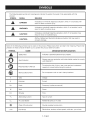
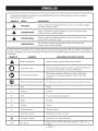
Some of the following symbols may be used on this product. Please study them and learn their meaning. Proper interpretation of these symbols will allow you to operate the product better and safer.
SYMBOL
A
NAME
DESIGNATION/EXPLANATION
Safety Alert
Indicates a potential personal injury hazard.
Eye Protection
Always wear eye protection with side shields marked to comply
with ANSI Z87.1.
Read Operator's Manual
To reduce the risk of injury, user must read and understand
operator's manual before using this product.
Wet Conditions Alert
Do not expose to rain or use in damp locations.
V
Volts
Voltage
A
Amperes
Current
mz
Hertz
Frequency (cycles per second)
W
Watt
Power
Minutes
Time
Alternating Current
Type of current
no
No Load Speed
Rotational speed, at no load
[]
Class II Construction
Double-insulated
Per Minute
Revolutions, strokes, surface speed, orbits etc., per minute
0
@
min
.../min
5 - English
construction
DOUBLE
INSULATION
EXTENSION
Double insulation is a concept in safety in electric power
tools, which eliminates the need for the usual three-wire
grounded power cord. All exposed metal parts are
isolated from the internal metal motor components with
protecting insulation. Double insulated tools do not need
to be grounded.
A
WARNING: The double insulated system is
intended to protect the user from shock resulting
from a break in the tool's internal insulation. Observe
all normal safety precautions to avoid electrical
shock.
NOTE: Servicing of a tool with double insulation requires
extreme care and knowledge of the system and should
be performed only by a qualified service technician. For
service, we suggest you return the tool to your nearest
Sears or other qualified service center for repair. Always
use original factory replacement parts when servicing.
ELECTRICAL
CONNECTION
This tool has a precision-built electric motor. It should be
connected to a power supply that is 120 volts, AC only
(normal household current}, 60 Hz. Do not operate this
tool on direct current (DC). A substantial voltage drop
will cause a loss of power and the motor will overheat. If
your tool does not operate when plugged into an outlet,
double-check the power supply.
CORDS
When using a power tool at a considerable distance from
a power source, be sure to use an extension cord that has
the capacity to handle the current the tool will draw. An
undersized cord will cause a drop in line voltage, resulting
in overheating and loss of power. Use the chart to determine the minimum wire size required in an extension cord.
Only round jacketed cords listed by Underwriter's Laboratories (UL) should be used.
When working outdoors with a tool, use an extension cord
that is designed for outside use. This type of cord is designated with "WA" or "W" on the cord's jacket.
Before using any extension cord, inspect it for loose or
exposed wires and cut or worn insulation.
**Ampere rating
(on tool faceplate)
0-2.0
2.1-3.4 3.5-5.0 5.1-7.0 7.1-12.0 12.1-16.0
Cord Length
Wire Size (A.W.G.)
25'
16
16
16
16
14
14
50'
16
16
16
14
14
12
100'
16
16
14
12
10
--
**Used on 12 gauge - 20 amp circuit
NOTE: AWG = American Wire Gauge
A
A
WARNING:
Keep the extension cord clear of the
working area. Position the cord so that it will not get
caught on lumber, tools or other obstructions while
you are working with a power tool. Failure to do so
can result in serious personal injury.
WARNING:
Check extension cords before each
use. If damaged replace immediately. Never use tool
with a damaged cord since touching the damaged
area could cause electrical shock resulting in serious
injury.
6 - English
PRODUCTSPECIFICATIONS
Chuck..........................................................
1/2in. Keyless
Blows Per Minute (BPM) .............................. 0-16,000/min.
Switch .......................................
Input ......................................
Variable Speed/Reversible
No Load Speed .................................
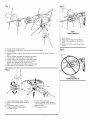
KNOW
YOUR HAMMER
0-1,000 r/rain. (RPM)
DRILL
The safe use of this product requires an understanding
of the information on the product and in this operator's
manual as well as a knowledge of the project you are
attempting. Before use of this product, familiarize yourself
with all operating features and safety rules.
AUXILIARY
HANDLE
ASSEMBLY
Your drill is equipped with an auxiliary handle for ease of
operation and to prevent loss of control.
DIRECTION
OF ROTATION
SELECTOR
Your drill has a direction of rotation (forward/reverse) selector
located above the variable speed switch for changing the
direction of bit rotation.
SPEED
Your hammer drill has a hammer speed of 0-16,000 BPM
(Blows Per Minute). Blows Per Minute is the number of
impacts per minute that the tool delivers in hammer mode.
5.02 Ibs.
CHUCK
The keyless chuck allows you to hand-tighten
the drill bit in the chuck jaws.
or release
LEVELS
Levels are located on the top and end of the motor housing to help keep the drill bit level during use.
LIVE TOOL INDICATOR
The live tool indicator is located on the handle of the drill
and indicates that the tool is connected to a power supply.
LOCK-ON
(FORWARD/REVERSE)
HAMMER
Net Weight .............................................................
KEYLESS
See Figure 1, page L
V, 60 Hz, AC only, 6Amps
BUTTON
The lock-on button is convenient for continuous
extended periods of time.
SPINDLE
LOCK
drilling for
BUTTON
The spindle lock keeps the chuck from turning while
installing and removing bits.
VARIABLE
SPEED
SWITCH
The variable speed switch delivers higher speed with
increased pressure and lower speed with decreased
pressu re.
7 - English
UNPACKING
PACKING
This product has been shipped completely assembled.
Hammer Drill with Auxiliary Handle Assembly
[] Carefully remove the product and any accessories from
the box. Make sure that all items listed in the packing
list are included.
Depth Stop Rod
A
WARNING:
Do not use this product if it is not
completely assembled or if any parts appear to be
missing or damaged. Use of a product that is not
properly and completely assembled could result in
serious personal injury.
[] Inspect the product carefully to make sure no breakage
or damage occurred during shipping.
Carrying Case
Operator's Manual
_
A
A
A
A
WARNING:
Do not allow familiarity with the product
to make you careless. Remember that a careless
fraction of a second is sufficient to inflict serious
injury.
WARNING: Always wear eye protection with side
shields marked to comply with ANSI Z87.1. Failure to
do so could result in objects being thrown into your
eyes and other possible serious injuries.
APPLICATIONS
Do not hold the chuck body with one
FORWARD/REVERSE
[] Hammer drilling in concrete, brick, or other masonry
See Figure 2, page i.
The direction of bit rotation is reversible and is controlled
SWITCH
See Figure 2, page i,
To turn the drill ON, depress the variable speed switch. To
turn it OFF, release the switch.
VARIABLE SPEED
The variable speed switch delivers higher speed and
torque with increased pressure and lower speed with
decreased pressure.
WARNING:
hand and use the power of the drill to tighten the
chuck jaws on the drill bit. The chuck body could slip
in your hand, or your hand could slip and come in
contact with the rotating drill bit. This could cause an
accident resulting in serious personal injury.
[] Drilling in metals
SPEED
WARNING:
Do not connect to power supply until
assembly is complete. Failure to comply could result
in accidental starting and possible serious injury.
The drill-driver has a keyless chuck that makes it simple to
tighten or release drill bits in the chuck jaws. The arrows
on the chuck indicate which direction to rotate the chuck
body in order to LOOK (tighten) or UNLOCK (release) the
drill bit.
[] Drilling in ceramics, plastics, fiberglass, and laminates
VARIABLE
WARNING:
Do not attempt to modify this product
or create accessories not recommended for use with
this product. Any such alteration or modification is
misuse and could result in a hazardous condition
leading to possible serious personal injury.
KEYLESS CHUCK
See Figure 2.
[] Drilling in all types of wood products (lumber, plywood,
paneling, composition board, and hard board)
[] Driving screws
If any parts are damaged or missing do
NOTE: You might hear a whistling or ringing noise from
the switch during use. Do not be concerned; this is a
normal part of the switch function.
,_k
You may use this product for the purposes listed below:
WARNING:
not operate this product until the parts are replaced.
Failure to heed this warning could result in serious
personal injury.
[] Do not discard the packing material until you have
carefully inspected and satisfactorily operated the
product.
[] If any parts are damaged or missing, please call
1-800-932-3188 for assistance.
LiST
by a selector located above the variable speed switch.
With the drill held in normal operating position, the direction of rotation selector should be positioned to the left
of the switch for drilling. The drilling direction is reversed
when the selector is to the right of the variable speed
switch.
8 - English
CAUTION:Topreventgeardamage,alwaysallow
the chuckto cometo a completestopbeforechangingthedirectionof rotation.
Tostopthe drill,releasetheswitchandallowthe chuckto
cometo a completestop.
NOTE:Thedrillwill notrununlessthedirectionof rotation
selectorispushedfullytothe leftor right.
Avoidrunningthedrillatlowspeedsforextendedperiods
oftime.Runningat lowspeedsunderconstantusagemay
causethedrillto becomeoverheated.
Ifthisoccurs,cool
thedrillbyrunningit withouta loadandatfullspeed.
_h,
WARNING:
Always unplug the tool when installing
or removing bits, adjusting settings, or when the tool
is not in use. Failure to unplug the tool may result in
accidental starting and serious personal injury.
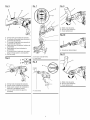
SPINDLE
See Figure 3, page L
[] To lock the spindle, depress and hold the spindle lock
button.
[] While keeping the button depressed, rotate the chuck
clockwise until the spindle clicks into a locked position
and will not rotate further.
[] To unlock, release the button.
NOTE: Always be sure the spindle lock button is released
and the spindle lock is disengaged before turning the drill
ON.
INSTALLING
BITS
See Figure 3, page L
[] Lock the spindle.
[] Rotate the chuck sleeve clockwise to open the chuck
jaws.
[]
Release the spindle lock.
to tighten the
NOTE: Rotate the chuck body in the direction of the
arrow marked LOCK to tighten the chuck jaws.
REMOVING
BITS
See Figure 3, page i,
[] Unplug the drill.
[] Lock the spindle.
THE AUXILIARY
HANDLE
ASSEMBLY
See Figure 5, page ii.
An auxiliary handle is packed with the drill for ease of
operation and to help prevent loss of control. The handle
can be rotated 360 ° and it can also be mounted on the
opposite side for left hand use.
To adjust the auxiliary handle assembly, loosen the handle
assembly by turning the handle counterclockwise.
Rotate the auxiliary handle assembly to the desired
operating position.
Securely tighten by turning the auxiliary handle clockwise.
NOTE: For convenience and ease of starting threads, the
hex nut has been trapped inside the molded slot in the
auxiliary handle.
The depth stop rod helps control the depth of drilled
holes.
NOTE: When properly installed, the teeth on the depth
stop rod should be aligned with the teeth indicator on the
depth stop clamp.
Adjust the depth stop rod so that the drill bit extends
beyond the end of the rod to the required drilling depth.
SELECTING
HAMMER
MODE
OR DRILLING
MODE
See Figure 6, page iL
WARNING:
Make sure to insert the drill bit straight
into the chuck jaws. Do not insert the drill bit into
the chuck jaws at an angle then tighten, as shown in
figure 4. This could cause the drill bit to be thrown
from the drill, resulting in possible serious personal
injury or damage to the chuck.
[] Rotate the chuck counterclockwise
chuck jaws securely on the bit.
USING
When drilling holes with the depth stop rod installed, the
desired hole depth has been reached when the end of the
rod comes in contact with the surface of the workpiece.
[] Unplug the drill.
Insert the drill bit.
[] Release the spindle lock.
Be sure the auxiliary handle is securely tightened. This
secures the depth stop rod in the depth stop clamp at the
desired depth of cut. It also secures the auxiliary handle.
LOCK
[]
[] Rotatethe chucksleevecounterclockwise
to openthe
chuckjaws.
[] Removethedrillbit.
To adjust for type of drilling, slide the drilling mode selector on top of the motor housing to hammer mode or drilling mode. The hammer mode symbol is on the left and the
drill bit symbol is on the right.
_IIL WARNING:
The hammer drill has not been de-
signed for reverse hammering.
Use carbide-tipped bits and select hammer mode when
drilling in hard materials such as brick, tile, concrete, etc.
Select normal drill mode when drilling with twist drills, hole
saws, etc., in soft materials.
LOCK-ON
BUTTON
See Figure 6, page ii,
This hammer drill is equipped with a lock-on feature,
which is convenient for continuous drilling for extended
periods of time. To lock-on:
9 - English
[] Depressthevariablespeedswitch.
[] Pushinandholdthelock-onbutton,locatedonthe
sideofthehandle.
[] Release
thevariablespeedswitch.
[] Release
the lock-onbuttonandthe drillwillcontinue
running.
[] Toreleasethe lock,depressandreleasethevariable
speedswitch.
If thelock-onfeatureisengagedduringuseandthe drill
becomesdisconnected
fromthe powersupply,disengage
thelock-onfeatureimmediately.
prevent the drill bit from slipping off-center as the hole
is started.
[] When drilling metals, use a light oil on the drill bit to
keep it from overheating. The oil will prolong the life of
the bit and increase the drilling action.
[] If the bit jams in the workpiece or if the drill stalls,
stop the tool immediately. Remove the bit from the
workpiece and determine the reason for jamming.
WOOD
DRILLING
[] For maximum performance,
for wood drilling.
use high speed steel bits
[] Select drilling mode.
_k WARNING:Beforeconnecting
the hammerdrillto
a powersupplysource,alwayscheckto besureit
is notin lock-onposition(depressandreleasethe
variablespeedswitch).Failureto ensurethatit is not
locked-oncouldresultinaccidentalstartingofthe
drillresultinginpossibleseriousinjury.Donot lock
thevariablespeedswitchin applications
wherethe
drillmayneedto besuddenlystopped.
DRILLING
See Figures 7 - 8, page iL
[] Begin drilling at a very low speed to prevent the bit
from slipping off the starting point. Increase the speed
as the drill bit bites into the material.
[] When drilling through holes, place a block of wood
behind the workpiece to prevent ragged or splintered
edges on the back side of the hole.
[] Do not lock the variable speed switch ON for
applications where the drill may need to be stopped
suddenly.
METAL DRILLING
[] For maximum performance,
for metal or steel drilling.
Levels are located on the top and end of the motor
housing to help keep the drill bit level during use.
[] Depress and release the variable speed switch to be
sure the drill is in the OFF position before connecting it
to a power supply.
[] Check the direction of rotation selector for the correct
setting (forward or reverse).
[] Secure the material to be drilled in a vise or with
clamps to keep it from turning as the drill bit rotates.
use high speed steel bits
[] Select drilling mode.
[] Begin drilling at a very low speed to prevent the bit
from slipping off the starting point.
[] Maintain a speed and pressure which allows cutting
without overheating the bit. Applying too much
pressure will:
Overheat the drill;
[] Plug the hammer drill into power supply. Hold the drill
firmly and place the bit at the point to be drilled.
Wear the bearings;
[] Depress the variable speed switch to start the drill. Do
not lock the variable speed switch ON for applications
where the drill may need to be stopped suddenly.
Produce off-center or irregular-shaped
[] Move the drill bit into the workpiece, applying only
enough pressure to keep the bit cutting. Do not force
the drill or apply side pressure to elongate a hole. Let
the tool do the work.
A
WARNING:
Be prepared for binding at bit
breakthrough. When these situations occur, the drill
has a tendency to grab and kick in the opposite
direction and could cause loss of control when
breaking through material. This loss of control can
result in possible serious injury. Do not lock the
variable speed switch ON in applications where the
drill may need to be stopped suddenly.
[] When drilling hard, smooth surfaces, use a center
punch to mark the desired hole location. This will
Bend or burn bits; and
holes.
[] When drilling large holes in metal, start with a small bit,
then finish with a larger bit. Also, lubricate the bit with
oil to improve drilling action and increase bit life.
MASONRY
DRILLING
[] For maximum performance, use carbide-tipped
masonry impact bits when drilling holes in brick, tile,
concrete, etc.
[] Slide adjustment button on hammer drill left for
hammer mode.
[] Apply light pressure and medium speed for best results
in brick.
[] Apply additional pressure for hard materials such as
concrete.
[] When drilling holes in tile, practice on a scrap piece to
determine the best speed and pressure. Begin drilling
at a very low speed to prevent the bit from slipping off
the starting point.
10 - English
A
A
WARNING: When servicing, use only identical
Craftsman replacement parts. Use of any other parts
may create a hazard or cause product damage.
WARNING: Always wear eye protection with side
shields marked to comply with ANSI Z87.1. Failure to
do so could result in objects being thrown into your
eyes and other possible serious injuries.
GENERAL
MAINTENANCE
Avoid using solvents when cleaning plastic parts. Most
plastics are susceptible to damage from various types of
commercial solvents and may be damaged by their use.
Use clean cloths to remove dirt, dust, oil, grease, etc.
,_,.
WARNING:
Do not at any time let brake fluids,
gasoline, petroleum-based products, penetrating
oils, etc., come in contact with plastic parts.
Chemicals can damage, weaken or destroy plastic
which may result in serious personal injury.
Electric tools used on fiberglass material, wallboard,
spackling compounds, or plaster are subject to
accelerated wear and possible premature failure because
the fiberglass chips and grindings are highly abrasive to
bearings, brushes, commutators, etc. Consequently, we
do not recommended using this tool for extended work on
these types of materials. However, if you do work with any
of these materials, it is extremely important to clean the
tool using compressed air.
LUBRICATION
All of the bearings in this tool are lubricated with a
sufficient amount of high grade lubricant for the life of
the unit under normal operating conditions. Therefore, no
further lubrication is required.
Only the parts shown on the parts list are intended to be
repaired or replaced by the customer. All other parts
should be replaced at a Sears Service Center.
CHUCK REMOVAL
See Figures 9 - 11, page ii,
The chuck can be removed and replaced with a new one.
[] Unplug the drill.
[] Insert a 5/16 in. or larger hex key into the chuck of the
drill and tighten the chuck jaws securely.
[] Tap the hex key sharply with a mallet in a clockwise
direction. This will loosen the screw in the chuck for
easy removal.
[] Open the chuck jaws and remove the hex key. Using a
screwdriver, remove the chuck screw by turning it in a
clockwise direction.
NOTE: The chuck screw has left hand threads.
[] Insert the hex key into the chuck and tighten the
chuck jaws securely. Tap sharply with a mallet in a
counterclockwise direction. This will loosen the chuck
on the spindle. It can now be unscrewed by hand.
TO RETIGHTEN A LOOSE CHUCK
The chuck may become loose on the spindle and develop
a wobble. Also, the chuck screw may become loose,
causing the chuck jaws to bind and prevent them from
closing. To tighten:
[] Unplug the drill.
[] Open the chuck jaws.
[] Insert a hex key into the chuck and tighten chuck jaws
securely. Tap the hex key sharply with a mallet in a
clockwise direction. This will tighten the chuck on the
spindle.
[] Open the chuck jaws and remove the hex key.
[] Tighten the chuck screw.
Look for these accessories at Sears retail:
[] High Speed Bits (For wood or metal) .............................................................................................................
1/2 in. Max.
[] Masonry Bits ...................................................................................................................................................
3/4 in. Max.
[] Wood Boring Bits ........................................................................................................................................
[] Hole Saws ...................................................................................................................................................
_1_ WARNING:
Current attachments
1-1/2 in. Max.
2-1/2 in. Max.
and accessories available for use with this product are listed above. Do not use
any attachments or accessories not recommended by the manufacturer of this product. The use of attachments
accessories not recommended can result in serious personal injury.
11 - English
or
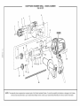
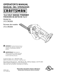
CRAFTSMAN
HAMMER
DRILL - MODEL
315.101371
NUMBER
27
SEENOTE
22
23
28
NOTE: The assembly shown represents an important part of the Double Insulated System. To avoid the possibility of alteration or damage to the System,
service should be performed by your nearest Sears Repair Center. Contact your nearest Sears Retail Store for Service Center information.
_"
CRAFTSMAN
HAMMER
DRILL - MODEL
NUMBER
315.101371
'_
J
The
model
number
will be found
on a plate
to the
motoror housing.
Always repair
mention
the model
number
in all
correspondence
regarding
yourattached
HAMMER
DRILL
when ordering
parts,
SEE BACK
PAGE FOR PARTS
ORDERING
|
INSTRUCTIONS
PARTS LIST
Key
No.
1
Part
Number
6613402
2
3
4
5
6
690033057
660299014
6796001
200269007
690426002
7
8
9
10
11
660299004
680260001
671752003
560398001
671796001
12
13
14
15
16
6309201
300676003
901092001
3067501
6936101
17
18
19
20
21
200294005
6326301
6721901
6703001
6616503
22
23
24
25
26
690297002
6929301
513394001
690338002
6616504
27
28
29
30
940045090
940114123
300188058
6341203
31
300912231
987000102
Description
Qty.
* Screw (Special) ................................................................................................
1/2 in. Keyless Chuck ......................................................................................
* Screw (M5 x 21 mm Pan Head) .......................................................................
* Spring Washer (M5) .........................................................................................
Gear Housing Assembly ..................................................................................
* Washer ............................................................................................................
1
1
2
3
1
3
* Screw (M5 x 18 mm Pan Head) .......................................................................
E-Ring ..............................................................................................................
Spindle Lock Pin .............................................................................................
Rubber O Ring .................................................................................................
1
1
1
1
Spring ..............................................................................................................
Washer ............................................................................................................
1
3
Output Gear Assembly ....................................................................................
Oil Seal ............................................................................................................
1
1
Intermediate
1
Gear And Pinion Assembly
........................................................
Spring ..............................................................................................................
Bearing Plate With Bearings ...........................................................................
Spring ..............................................................................................................
Steel Ball (5 mm Dia.) ......................................................................................
Spring Washer .................................................................................................
1
1
1
2
4
* Screw (M4 x 18 mm Pan Head) .......................................................................
Hammer Adjust Plate ......................................................................................
Retaining Ring .................................................................................................
Hammer Adjust Button ....................................................................................
Washer ............................................................................................................
4
1
1
1
1
* Screw (M4 x 8 mm Pan Head) .........................................................................
Data Label .......................................................................................................
2
1
Logo Label ......................................................................................................
Auxilary Handle Assembly ...............................................................................
Guide Rod .......................................................................................................
1
1
1
Carrying Case (Not Shown) .............................................................................
Operator's Manual
1
* Standard Hardware Item = May Be Purchased Locally
** Available From Div. 98 - Source 980.0
*** Complete
assortment
available
at your Nearest
13 - English
Sears Retail Store
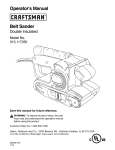
RIGHT
FORMACORRECTA
A - Drill bit (broca)
B - Chuck jaws (mordazas del portabrocas)
C - Keyless chuck (portabrocas de apriete sin
Ilave)
D - Spindle lock button (boton del seguro del
husillo)
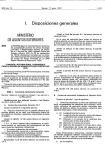
A - Auxiliary handle (mango auxiliar)
B - Drilling/hammer mode selector (selector de modalidad de taladrado)
C- Levels (niveles)
D - Direction of rotation selector [forward/reverse] (selector de sentido de rotacion [adelante /
atr_s])
E - Live tool indicator (indicador de herramienta conectada)
F - Lock-on button (boton del seguro de encendido)
G- Variablespeed switch (interruptor de velocidad variable)
H - Spindle lock button (interruptor de velocidad variable)
I - Keyless chuck (portabrocas de apriete sin Ilave)
J - Depth stop clamp (abrazaderalimitadora de profundidad)
K - Depth stop rod (barra limitadora de profundidad)
WRONG
FORMAINCORRECTA
A- Unlock [release] (quitar seguro [soltar])
B - Keyless chuck (portabrocas de apriete sin
Ilave)
C- Lock [tighten] (seguro [apretar])
D - Variablespeed switch (interruptor de
velocidad variable)
E - Forward (marcha adelante)
F - Direction of rotation selector [forward/
reverse] (selector de sentido de rotacion
[adelante/ atr_s])
G- Reverse (marcha atr_s)
F_[g.g
B
A
B
C
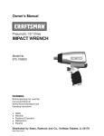
A - Mallet (mazo de goma)
B - Hex key (llave hexagonal)
C - Chuck (portabrocas)
A - Drilling depth (profundidad de taladrado)
B - To decreasedrilling depth (para disminuir la
profundidad de taladrado)
C - To increasedrilling depth (para aumentar la
profundidad de taladrado)
D - Depth stop clamp (abrazadera limitadora de
profundidad)
E - Depth gauge rod (barra limitadora de
profundidad)
F - To loosen auxiliary handle and clamp (para
afiojar el mango auxiliary la abrazadera)
G- Drill bit (broca)
A - Screwdriver (destornillador)
A - Endview (vista de frente)
B- Level (nivel)
A
A - Drilling mode (modalidad de taladrado)
B - Hammer mode (modalidad de percusion)
C - Mode selector (selector de modalidad de
percusion o de taladrado normal)
D - Lock-on button (boton del seguro de
encendido)
A - Mallet (mazo de goma)
B - Hex key (llave hexagonal)
C - Chuck (portabrocas)
A- Level (nivel)
A
iADVERTENCIA!
Lea todas las instrucciones.
El
incumplimiento de las instrucciones
que se ofrecen
a continuaci6n
puede causar descargas el_ctricas,
incendios y lesiones graves. El t_rmino "herramienta
el_ctrica" empleado en todos los avisos de advertencia
que se enumeran m_s adelante se refiere alas
herramientas el_ctricas de cable (al_mbricas) y de
baterias (inal_mbricas).
GUARDE ESTAS INSTRUCCIONES
SEGURIDAD EN EL AREA DE TRABAJO
[]
[]
[]
Evite un arranque accidental
de la unidad. AsegSrese
de que el interruptor
est_ en la posici6n de
apagado antes de conectar
la herramienta.
Portar
las herramientas el_ctricas con el dedo puesto en el
interruptor, o conectarlas estando _ste encendido,
propicia accidentes.
[]
Retire toda Ilave o herramienta
de ajuste antes
de encender la herramienta
el_ctrica. Toda Ilave o
herramienta de ajuste dejada en una pieza giratoria de la
herramienta el_ctrica puede causar lesiones.
No estire el cuerpo para alcanzar mayor distancia.
Mantenga una postura firme y buen equilibrio en todo
momento.
De esta manera tendr& un mejor control de la
herramienta el_ctrica en situaciones inesperadas.
[]
Mantenga limpia y bien iluminada
el _rea de trabajo.
Un _rea de trabajo mal despejada o mal iluminada
propicia accidentes.
No utilice herramientas motorizadas
en atm6sferas
explosivas,
como las existentes
alrededor
de Ifquidos,
gases y polvos inflamables.
Las herramientas el_ctricas
generan chispas que pueden encender el polvo y los
vapores inflamables.
[]
Use ropa adecuada.
No use prendas holgadas
ni
alhajas. Mantenga el cabello, la ropa y los guantes
alejados de las piezas m6viles. Las prendas holgadas,
las alhajas y el cabello largo pueden engancharse en las
piezas m6viles.
[]
Si se suministran
dispositivos
para conectar
mangueras
de extracci6n
y captaci6n
de polvo,
asegSrese de que _stas est_n bien conectadas
y se
usen correctamente.
El uso de estos dispositivos
puede
disminuir los peligros relacionados con el polvo.
No vista prendas holgadas ni alhajas. Rec6jase el
cabello si Io usa largo. Las prendas holgadas y las
alhajas, as[ como el cabello largo, pueden set atra[das
hacia el interior de las aberturas de ventilaci6n.
[]
Mantenga alejados a los ni_os y circunstantes
al
maniobrar
una herramienta
el@ctrica. Toda distracci6n
puede causar la p_rdida del control de la herramienta.
SEGURIDAD
ELI'=CTRICA
[]
[]
[]
Las clavijas de las herramientas
el@ctricas deben
corresponder
alas tomas de cordente donde se
conectan.
Nunca modifique
la clavija de ninguna
forma. No utilice clavijas adaptadoras
en herramientas
el_ctricas
provistas de contacto
a tierra. AI conectar
la clavija original en una toma de corriente compatible se
reduce el riesgo de una descarga el_ctrica.
Evite el contacto
del cuerpo
con las superficies
de
objetos que est_n haciendo tierra o est_n conectados
a
_sta, como tuberias, radiadores, estufas y refrigeradores.
El riesgo de descarga el_ctrica es mayor cuando el cuerpo
est& haciendo tierra.
No exponga las herramientas
el@ctricas a la Iluvia ni
a condiciones
de humedad.
La penetraci6n
de agua
en una herramienta
el_ctrica aumenta el riesgo de
descargas
el_ctricas.
[]
No maltrate el cable el_ctrico. Nunca utilice el cable para
trasladar, desconectar
o tirar de la herramienta
el_ctrica.
Mantenga el cable alejado del calor, del aceite, de bordes
afilados y de piezas m6viles. Los cables el_ctricos daSados
o enredados aumentan el riesgo de descargas el_ctricas.
[] AI utilizar una herramienta
el_ctrica a la intemperie, use
un cable de extensi6n apropiado
para extedores.
AI usar
un cable adecuado para exteriores se disminuye el riesgo
de descargas el_ctricas.
SEGURIDAD
PERSONAL
[]
[]
AI usar herramientas
el@ctricas, mant@ngase alerta,
preste atenci6n a Io que est6 haciendo y aplique el
sentido corn[in. No utilice la herramienta
el_ctrica
si est_ cansado o se encuentra
bajo los efectos de
alguna droga, alcohol o medicamento.
Un momento
de inatenci6n al utilizar una herramienta el_ctrica puede
causar lesiones corporales graves.
Use equipo de seguridad.
Siempre p6ngase
protecci6n
ocular. El uso de equipo de seguridad,
como mascarilla contra el polvo (cubrebocas), calzado
de seguddad, casco y protecci6n para los o[dos en las
circunstancias
en que corresponda,
disminuye el riesgo
de lesiones.
[]
[] No utilice la unidad subido en una escalera o en
un soporte inestable, Una postura estable sobre
una superficie s61ida permite un mejor control de la
herramienta el_ctrica en situaciones inesperadas.
EMPLEO Y CUIDADO DE LA HERRAMIENTA
ELI_CTRICA
[]
No fuerce la herramienta
el_ctrica. Utilice la
herramienta
el_ctrica adecuada para carla trabajo. La
herramienta el_ctrica adecuada funciona mejor y con
menos riesgos, si adem&s se maneja a la velocidad para
la que fue diseSada.
[]
No utilice la herramienta
si el interruptor no enciende
o no apaga. Cualquier herramienta el_ctrica que no
pueda controlarse con el interruptor es peligrosa y debe
repararse.
Desconecte
la clavija del suministro
de corriente
o retire el paquete de baterias de la herramienta
el@ctrica, segSn sea el caso, antes de efectuarle
cualquier ajuste, cambiade
accesorios
o guardarla.
Tales medidas preventivas de seguridad reducen el riesgo
de poner en marcha accidentalmente
la herramienta.
Guarde las herramientas
el_ctricas
desocupadas
fuera del alcance de los niSos y no permita que las
utilicen personas no familiarizadas
con elias o con
estas instrucciones.
Las herramientas el_ctricas son
peligrosas en manos de personas no capacitadas
en su
[]
[]
USO.
[]
Preste servicio alas herramientas
el_ctricas.
Revise
que no haya piezas m6viles desalineadas
ni trabadas
o rotas, ni cualqueir
otra condici6n
que pueda afectar
el funcionamiento
de la herramienta.
Si la herramienta
el_ctrica
se daSa, II6vela a reparar antes de usarla.
Gran cantidad de accidentes son causados pot
herramientas el_ctricas mal cuidadas.
[]
Mantenga las herramientas
de corte afiladas y limpias.
Las herramientas de corte bien cuidadas y con bordes
3- EspaSol
[]
bien afilados, tienen menos probabilidad de trabarse en la
pieza de trabajo y son m_s f_ciles de controlar.
Utilice la herramienta
el_ctrica, los accesorios
y brocas,
hojas de torte, ruedas de esmeril, etc. de conformidad
con estas instrucciones,
y de la forma apropiada
para
cada una de dichas herramientas,
tomando
en cuenta
las condiciones
de trabajo y la tarea por realizar. Si se
utiliza la herramienta el_ctrica para operaciones diferentes
de las indicadas podr[a originar una situaci6n peligrosa.
s6lo piezas de repuesto id_nticas. De esta manera se
mantiene )a seguridad de )a herramienta e)_ctrica.
_,
[]
SERVIClO
[]
S6lo un t_cnico calificado
debe hacer reparaciones
de la herramienta
el_ctrica, y para ello debe usar
[]
P6ngase protectores
para los o[dos cuando use
herramientas
de impacto. La exposici6n al ruido puede
causar p_rdida del o[do.
[]
Utilice los mangos auxiliares que se suministran
con
la herramienta.
Cualquier p_rdida de control puede
causar lesiones.
[]
Sujete la herramienta
pot las superficies
aisladas
de sujeci6n al efectuar una operaci6n
en la cual la
herramienta
de corte pueda entrar en contacto
con
cables ocultos o con su propio cable el_ctrico. Todo
contacto de una herramienta con un alambre cargado,
transmitir_ la carga alas piezas met_licas externas de la
herramienta y aplicar_ una descarga el_ctrica al operador.
Familiar[cese con su herramienta
el_ctrica. Lea
cuidadosamente
el manual del operador.
Aprenda sus
usos y limitaciones,
asi como los posibles peligros
especfficos
de esta herramienta.
AI cumplir esta regla
se reduce el riesgo de descargas el_ctricas, incendios o
lesiones graves.
[]
Revise en busca de piezas da_adas. Antes de seguir
utilizando
la herramienta,
es necesario
inspeccionar
cuidadosamente
toda protecci6n
o pieza da_ada, para
saber si funcionar4
correctamente
y desempe_ar4
la
funci6n que se espera de ella. Verifique la alineaci6n
de las partes m6viles, que no est_n trabadas,
que
no haya piezas rotas, que est@n bien montadas
y cualquier
otra condici6n
que pudiera afectar
su funcionamiento.
Toda protecci6n
o pieza que
est_ daSada debe repararse apropiadamente
o
reemplazarse
en un centro de servicio autorizado.
AI
cumplir esta regla se reduce el riesgo de una descarga
e)_ctrica, )ncendio o )esi6n grave.
[]
AsegSrese de que est_ en buen estado el cable de
extensi6n.
Si necesita un cable de extensi6n,
utilice
uno con el calibre suficiente
para soportar
la corriente
que consume el producto.
Se recomienda
que los
conductores
sean de calibre 14 (AWG) pot Io menos,
en el caso de un cable de extensi6n de 50 pies (15
metros) de largo o menos. Se recomienda
no utilizar
cables de m4s de 100 pies (30 metros) de largo. En
caso de duda, utilice un cable del calibre m4s grueso
siguiente.
Cuanto menor es el nSmero de calibre,
tanto mayor es el grueso del cable. Un cable de un
calibre insuficiente causa una ca[da del voltaje de I[nea, y
produce recalentamiento
y p_rdida de potencia.
Inspeccione la madera y elimine todos los clavos
presentes antes de usar esta herramienta.
AI cumplir
esta regla se reduce el riesgo de lesiones graves.
[]
Prot_jase
los pulmones.
Use una careta o mascarilla
contra el polvo si la operaci6n
Io genera en gran
cantidad.
AI cumplir esta reg)a se reduce e) desgo de
lesiones graves.
Prot_jase
los oMos. Durante peHodos prolongados
de utilizaci6n
del producto,
p6ngase protecci6n
para
los o[dos. AI cumplir esta reg)a se reduce e) desgo de
lesiones graves.
[]
Inspeccione
peri6dicamente
los cables el_ctricos
de
las herramientas
y, si est4n da_ados, haga que los
reparen en el centro de servicio calificado
o Sears
m4s cercano.
Observe constantemente
la ubicaci6n
[]
A
AI dar servicio a una herramienta
el@ctrica,
utilice solamente
piezas de repuesto id@nticas.
Siga las instrucciones se_aladas
en la secci6n
"Mantenimiento"
de este manual. El empleo de piezas
no autorizadas o el incumplimiento de las instrucciones
de mantenimiento
puede significar un desgo de descarga
el_ctrica o de lesiones.
[]
Siempre p6ngase protecci6n
ocular con protecci6n
lateral con la marca de cumplimiento
de la norma
ANSI Z87.1. La inobservancia de esta advertencia puede
causar el lanzamiento de objetos hacia los ojos y otras
lesiones graves.
[]
Para reducir el riesgo de lesiones,
e) usuado debe )eer e) manual de instrucciones.
del cable el_ctrico. AI cumplir esta regla se reduce el
desgo de una descarga el_ctrica o incendio.
[]
[]
iADVERTENC(A!
[]
Si est4 daSado el cord6n de corriente,
debe ser
reemplazado L_nicamente pot el fabricante o en un centro
de servicio autorizado para evitar riesgos.
Guarde estas instrucciones.
ConsL_ltelas con frecuencia
y empl_elas para instruir a otras personas que puedan
utilizar esta herramienta. Si presta a alguien esta
herramienta, faci)[te)e tambi_n )as )nstrucciones.
ADVERTENClA:
Atgunos polvos generados al efectuar operaciones de lijado, aserrado, esmerilado, tatadrado y
constructivas de otto tipo, contienen sustancias quimicas que se sabe son causa de cancer, defectos congenitos y otras
atteraciones del aparato reproductor. Algunos ejemplos de estas sustancias quimicas son:
• plomo de las pinturas que contienen este metal,
silicio cristatino de los ladrillos, el cemento y otros materiales de construcci6n, y
arsenico y cromo de la madera quimicamente tratada.
El riesgo de la exposici6n a estos compuestos varia segOn la frecuencia con que se reatice este tipo de trabajo. Para reducir
la exposici6n personal a este tipo de compuestos: trabaje en espacios bien ventitados, y con equipo de seguridad aprobado,
como son caretas para el potvo especialmente disefiadas para fittrar particutas microsc6picas.
4- Espafiol
Lassiguientespalabrasdese_alizaci6n
y sussignificados
tienenporobjetoexplicarlosnivelesderiesgo
relacionados
conesteproducto.
SIMBOLO
SEI_AL
SIGNIFICADO
PELIGRO:
Indica una situaci6n peligrosa inminente, la cual, si no se evita, causar_
la muerte o lesiones graves.
,_
ADVERTENCIA:
Indica una situaci6n peligrosa posible, la cual, si no se evita, puede
causar la muerte o lesiones graves.
,_
PRECAUCION:
Indica una situaci6n peligrosa posible, la cual, si no se evita, puede
causar lesiones menores o leves.
PRECAUCI()N:
(Sin el s[mbolo de alerta de seguridad.) Indica una situaci6n que
puede producir da_os materiales.
En este producto es posible que se empleen algunos de los s[mbolos siguientes. Sea tan amable de estudiarlos y
aprender su significado. La correcta interpretaci6n de estos s[mbolos le permitir_ utilizar el producto con mayor eficiencia
y seguridad.
S|MBOLO
A
0
@
@
DENOMINACION/EXPLICACI6N
NOMBRE
Alerta de seguridad
Indica un peligro posible de lesiones personales.
Protecci6n ocular
Siempre p6ngase protecci6n ocular con protecci6n lateral con
la marca de cumplimiento de la norma ANSI Z87.1.
Lea manual del operador
Para reducir el riesgo de lesiones, el usuario debe leer y
comprender el manual del operador antes de usar este
producto.
Alerta de condiciones
No exponga la unidad a la Iluvia ni la use en lugares h0medos.
h0medas
V
Volts
Voltaje
A
Amperes
Corriente
Hz
Hertz
Frecuencia (ciclos por segundo)
W
Watts
Potencia
Minutos
Tiempo
Corriente alterna
Tipo de corriente
no
Velocidad en vac[o
Velocidad de rotaci6n, en vac[o
[]
Fabricaci6n Clase II
Fabricaci6n con doble aislamiento
Por minuto
Revoluciones, carreras, velocidad superficial, 6rbitas, etc., por
minuto
min
.../min
5 - Espa_ol
DOBLE
AISLAMIENTO
CABLES
El doble aislamiento, una caracter[stica de seguridad de
las herramientas el_ctricas, elimina la necesidad de usar
el tradicional cable el_ctrico de tres conductores con
conexi6n a tierra. Entre las partes met_licas externas y
los componentes met_licos internos del motor existe
un aislamiento protector. Las herramientas con doble
aislamiento no requieren conexi6n a tierra.
A
ADVERTENCIA:
El sistema de doble aislamiento
redondo con registro de Underwriter's
Laboratories (UL).
AI trabajar a la intemperie con una herramienta, utilice un
cable de extensi6n fabricado para uso en exteriores. Este
tipo de cable Ileva las letras "WA" o "W" en el forro.
de seguridad, para evitar descargas
NOTA: El mantenimiento de una herramienta con doble
aislamiento requiere sumo cuidado y conocimiento del
sistema, y s61o deben realizarlo t_cnicos de ser_/icio
calificados. Si la herramienta Ilegara a necesitar
reparaci6n, le sugerimos Ilevarla al centro de servicio
calificado o Sears m_s cercano. Utilice siempre piezas de
repuesto originales (de f_brica) al dar servicio a la unidad.
CONEXION
Si media una distancia importante entre la herramienta
el_ctrica y la fuente de voltaje, aseg0rese de que el cable
de extensi6n que utilice tenga la capacidad suficiente
para soportar la corriente que consume la herramienta.
Un cable de calibre insuficiente causa una ca[da de
voltaje en la I[nea, que produce a su vez recalentamiento
y p_rdida de potencia. B_sese en la tabla suministrada
para determinar el grueso m[nimo requerido del cable de
extensi6n. Deben utilizarse solamente cables con forro
fue creado para proteger al usuario de descargas
el_ctricas producidas por ruptura del aislamiento
interno de la herramienta. Observe todas las
precauciones
el_ctricas.
DE EXTENSION
ELleCTRICA
El motor el_ctrico de esta herramienta fue fabricado con
precisi6n. Debe conectarse 0nicamente a una linea de
voltaje de 120 volts, de corriente alterna (corriente
normal de uso dom_stico}, 60 hertz. No use esta
herramienta con corriente continua (c.c.). Una caida de
voltaje importante ocasionar_ reducci6n de la potencia y
recalentamiento del motor. Si la herramienta no funciona
al conectarla en una toma de corriente, vuelva a verificar
el suministro de voltaje.
Antes de utilizar un cable de extensi6n, inspecci6nelo
para ver si tiene conductores flojos o expuestos y
aislamiento cortado o gastado.
**Amperaje
(aparece en la placa frontal)
0-2.0
Longitud
del cable
2.1-3.4 3.5-5.0 5.1-7.0 7.1-12.0 12.1-16.0
Calibre de los conductores
(AWG)
25'
16
16
16
16
14
14
50'
16
16
16
14
14
12
100'
16
16
14
12
10
--
**Se usa en los circuitos de calibre 12, 20 amperes
NOTA: AWG = Norma estadounidense en calibres de conductores
A
ADVERTENCIA:
Mantenga el cable de extensi6n
fuera del _rea de trabajo. AI trabajar con una
herramienta el_ctrica, acomode el cable de tal
manera que no pueda enredarse en la madera,
herramientas ni en otros obst_culos. La falta de
atenci6n a esta advertencia puede originar lesiones
graves.
A
6- EspaSol
ADVEFITENCIA:
Inspeccione los cables de
extensi6n cada vez que vaya a usarlos. Si est_n
daSados, reempl_celos de inmediato. Nunca utilice
la herramienta con un cable daSado, porque el
contacto con una parte expuesta puede producir
una descarga el_ctrica que ocasione lesiones
graves.
ESPECIFICACIONES
DEL
PRODUCTO
Portabrocas ............ 13 mm (1/2 pulg.), de apriete sin Ilave
Golpes por minuto (GPM) .............................
Interruptor ............. Velocidad variable y rotaciOn invertible
Corriente de entrada ........ 120 V, 60 Hz, 6 A, sOlo corr. alt.
Peso neto .................................................. 2,28 kg (5,02 Ib)
Velocidad en vado .................... De 0 a 1 000 r/min. (RPM)
FAMILIAR{CESE
PERCUSION
CON EL TALADRO
DE
PORTABROCAS
Para usar este producto con la debida seguridad se debe
comprender la informaciOn indicada en la herramienta
misma yen este manual, y se debe comprender tambi_n
el trabajo que intenta realizar. Antes de usar este producto,
familiar[cese con todas las caracter[sticas de funcionamiento
y normas de seguridad del mismo.
MANGO
AUXIMAR
El taladro est_ provisto de un mango auxiliar que facilita
su manejo y evita la p_rdida de control.
NIVELES
El taladro cuenta con dos niveles, uno en la parte
superior y otto en la posterior del alojamiento del motor,
para mantener nivelada la broca durante el uso de la
herramienta.
INDICADOR
DE HERRAMIENTA
CONECTADA
La luz indicadora de herramienta conectada est_ situada
en el mango de la herramienta, e indica que _sta est_
enchufada a un suministro de corriente.
SELECTOR
DEL SENTIDO DE ROTACI()N
(MARCHA ADELANTE / ATRAS)
BOTON
El taladro est_ provisto de un selector de sentido de giro
(marcha adelante o atr_s), situado arriba del interruptor de
velocidad variable, que permite cambiar la direcciOn en
que gira la broca.
SEGURO
VELOOIDAD
SIN LLAVE
El portabrocas de apriete sin Ilave permite apretar o afiojar
a mano la broca en las mordazas del portabrocas.
Vea la figura 1, pagina i,
SlSTEMA
DE APRIETE
De 0 a 16 000
DE PEROUSlON
El taladro permite una velocidad de percusiOn de 0 a
16000 GPM (golpes por minuto). Los golpes por minuto
son el nOmero de impactos que produce la herramienta en
modo de percusiOn.
DEL SEGURO
DE ENCENDIDO
El botOn del seguro de encendido es Otil para un
taladrado continuo durante per[odos prolongados.
DEL HUSILLO
El seguro del husillo impide que el portabrocas
cuando se instalan o quitan brocas.
gire
INTERRUPTOR
DE VELOCIDAD
VARIABLE
La velocidad del giro var[a seg0n se aplique mayor o
menor presiOn en el gatillo de velocidad variable: a mayor
presiOn, mayor velocidad, y viceversa.
7- Espa_ol
DESEMPAQUETADO
Este producto
[]
A
LISTA DE EMPAQUETADO
se empaca
completamente
armado.
Taladro de percusi6n
Extraiga cuidadosamente
de la caja el producto y los
accesorios. Compruebe que est_n presentes todos los
art[culos enumerados en la lista de empaquetado.
Barra limitadora
Estuche
Inspeccione cuidadosamente
el producto, para verificar
que no haya sufrido ninguna rotura o dafio durante el
transporte.
[]
No deseche el material de empaquetado
inspeccionado
el producto con cuidado
satisfactoriamente.
hasta que haya
y la haya utilizado
A
A
A
Si hay piezas dafiadas o faltantes, s[rvase Ilamar al
1-800-932-3188,
donde le brindaremos asistencia.
A
A
ADVERTENClA:
No permita que su familarizaci6n
con el producto Io vuelva descuidado. Tenga presente
que basta un instante de descuido para que se
produzca una lesi6n grave.
ADVERTENClA:
Siempre p6ngase protecci6n ocular
con protecci6n lateral con la marca de cumplimiento
de la norma ANSI Z87.1. La inobservancia de esta
advertencia puede causar el lanzamiento de objetos
hacia los ojos y otras lesiones graves.
APLICACiONES
Este producto puede emplearse
Taladrado productos de madera (madera aserrada, madera
contrachapada,
paneles, madera compuesta y madera dura)
[]
Taladrado
laminado
en cer_.mica, pl_.sticos, fibra de viddo y material
[]
Taladrado
en metales
Enroscar tornillos
[]
Taladrado de percusi6n
de mamposter[a
con puntas de destornillador
en hormig6n,
INTERRUPTOR
DE VELOCIDAD
Vea la figura 2, p_gina L
de profundidad
ladrillo y otros tipos
VARIABLE
Para ENCENDER el taladro, oprima el interruptor de
velocidad variable. Para APAGAFI la unidad, suelte el
interruptor de velocidad variable.
VELOCIDAD
VARIABLE
La velocidad del giro y la fuerza de torsi6n vat[an segOn se
aplique mayor o menor presi6n en el gatillo: a mayor presi6n,
mayor velocidad y fuerza de torsi6n, y viceversa.
ADVERTENClA:
Si hay piezas dafiadas o faltantes,
no utilice este producto sin haber reemplazado todas
las piezas. La inobservancia
de esta advertencia podr[a
causar lesiones serias.
ADVERTENClA:
No intente modificar esta
herramienta ni fabricar accesorios no recomendados
para ella. Cualquier alteraci6n o modificaci6n
constituye
maltrato y puede causar una condici6n peligrosa, con
las consecuentes
lesiones corporales graves.
ADVERTENClA:
No conecte la unidad al suministro
de corriente sin haber terminado de armada. De
Io contrario, la unidad puede ponerse en marcha
accidentalmente,
con riesgo de causar lesiones graves.
NOTA: Es posible que el interruptor emita un silbido
o zumbido durante el uso. No debe ser motivo de
preocupaci6n;
es parte normal del funcionamiento
del
interruptor.
PORTABROCAS
DE APRIETE
SIN LLAVE
Vea la figura 2.
El taladro-destornillador
dispone de un portabrocas de
apriete sin Ilave que facilita apretar o aflojar la broca en las
mordazas del portabrocas.
Las flechas del portabrocas
indican en qu_ direcci6n debe girarse _ste para apretar
(LOCK) o aflojar (UNLOCK) la broca.
_lb
para los fines siguientes:
[]
[]
de mango auxiliar
Manual del operador
ADVERTENClA:
No utilice este producto si
alguna pieza incluida en la lista de contenido ya est,.
ensamblada al producto cuando Io desempaqueta.
El
fabricante no ensambla las piezas de esta lista en el
producto. Estas deben set instaladas pot el usuario. El
uso de un producto que puede haber sido ensamblado
de forma inadecuada podr[a causar lesiones personales
graves.
[]
con sistema
ADVERTENCIA:
No sujete con la mano el
portabrocas con la intenci6n de apretar la broca
en las mordazas usando la potencia del taladro. El
portabrocas podr[a resbal&rsele en la mano, o la mano
misma resbalarse y entrar en contacto con la sbroca
que gira. Esto puede causar un accidente y lesiones
corporales graves.
MARCHA
ADELANTE
Vea la figura 2, p_gina i.
/ ATR.,_S
El sentido de rotaci6n de la broca es invertible y se controla
con un selector situado arriba del interruptor de velocidad
variable. Con el taladro sostenido en la posici6n normal
de trabajo, el selector de sentido de rotaci6n debe estar
a la izquierda del interruptor de velocidad variable para
el taladrado. El sentido de rotaci6n est& invertido cuando
el selector se encuentra a la derecha del interruptor de
velocidad variable.
8- Espafiol
PRECAUCI(_N:
Para no dafiar el engranaje, antes
de cambiar el sentido de rotaci6n espere a que el
portabrocas se detenga por completo.
Para detener el taladro, suelte el interruptor de velocidad
variable y espere a que el portabrocas se detenga pot
completo.
NOTA: El taladro no funcionar_ si el selector de rotaci6n
se pasa completamente
hasta la izquierda o la derecha.
C()MO
no
ADVERTENCIA:
Desconecte siempre la herramienta
antes de poner o retirar brocas o de cambiar los
ajustes, as[ como al terminar de usarla. Si no la
desconecta, la herramienta puede ponerse en marcha
accidentalmente,
con el consiguiente
desgo de lesiones
graves.
SEGURO
DEL HUSILLO
Vea la figura 3, pggina L
y mantenga
oprimido
LA TALADRADO
DE PERCUSI()N
O
DE TALADRADO
NORMAL
Vea la figura 5, pggina ft.
Evite hacer funcionar el taladro a baja velocidad pot per[odos
largos. El funcionamiento
constante a velocidades bajas
puede causar recalentamiento
del taladro. De ocurrir esto,
enfr[e el taladro haci_ndolo funconar sin carga a plena
velocidad.
A
ESCOGER
Para escoger el tipo de taladrado, ponga el selector
correspondiente,
situado en la parte superior del alojamiento
del motor, en la modalidad de taladrado de percusi6n o
de taladrado normal, segL_n Io requiera. El s[mbolo de la
modalidad de taladrado de percusi6n est,. a la izquierda, y el
de taladrado normal, a la derecha.
ADVERTENCIA:
El taladro de percusi6n no est_
dise_ado para la percusi6n en direcci6n inversa.
Emplee brocas con punta de carburo y seleccione la
modalidad de percusi6n al taladrar en materiales duros como
ladrillo, mosaico, hormig6n, etc.
Seleccione la modalidad de taladrado normal cuando
vaya a usar brocas helicoidales, sierras cil[ndricas, etc., en
matedales blandos.
BOT(_N DEL SEGURO DE ENCENDIDO
Vea la figura 6, pggina ft.
[]
Para trabar el husillo, presione
bot6n del seguro del husillo.
el
[]
Mientras mantiene el bot6n oprimido, gire el portabrocas
a la derecha hasta que el husillo entre en posici6n de
bloqueo y no gire m_s.
Este taladro de percusi6n est,. provisto de un seguro de
encendido, el cual es muy 0til cuando se requiere taladrado
continuo durante per[odos prolongados.
Para poner el
seguro de encendido:
[] Para desbloqueado,
suelte el but6n.
NOTA: Antes de encender el taladro, siempre aseg0rese de
soltar el bot6n del seguro del husillo y de que realmente est_
desembragado
dicho seguro.
[]
Optima
[]
INSTALACI()N
[]
Empuje hacia adentro y no deje salir el bot6n del seguro
de encendido, el cual est,. situado en el costado del
mango.
Suelte el interruptor de velocidad variable.
DE LAS
Vea la figura 3, pggina i.
[] Desenchufe el taladro.
BROCAS
[]
Suelte el bot6n del seguro
seguir_t funcionando.
Asegure
[]
[]
Gire a la derecha el collar del portabrocas,
mordazas.
Introduzca la broca.
[]
Suelte el bot6n del seguro del husillo.
el husillo.
de encendido
y el taladro
para abrir las
Para quitar el seguro, optima el interruptor de velocidad
variable y su_ltelo.
Si el seguro de encendido est,. puesto al usar el taladro,
y _ste se desconecta
accidentalmente
del suministro de
voltaje, quite de inmediato el seguro de encendido.
ADVERTENClA:
Antes de conectar el taladro de
percusi6n al sumJnistro de corriente, siempre verifique
que el interruptor no est_ en la posici6n de encendido
(optima y suelte el interruptor de velocidad variable).
Si no se cerciora de quitar el seguro de encendido,
el taladro puede arrancarse accidentalmente
y
ocasionar lesiones graves. No asegure el interruptor
en la posici6n de encendido cuando el trabajo pueda
requerir una inmediata detenci6n del taladro.
ADVERTENClA:
AsegOrese de introducir bien
alineada la broca en las mordazas del portabrocas.
No debe apretarse la broca si entr6 desalineada en las
mordazas del portabrocas,
como se ilustra en la figura
4. La broca podr[a salir disparada del taladro y causar
lesiones corporales graves o daSos al portabrocas.
Gire a la izquierda el portabrocas
la broca en las mordazas.
para apretar firmemente
NOTA: Para apretar las mordazas del portabrocas,
gire el
cuerpo de _ste en la direcci6n de la fiecha marcada con
la palabra LOCK (Apretar).
RETIRO
variable.
[]
[]
[]
el interruptor de velocidad
DE LAS BROCAS
Vea la figura 3, pggina i.
[] Desenchufe el taladro.
[]
Asegure
[]
[]
Gire a la izquierda
mordazas.
Retire la broca.
[]
Suelte el bot6n del seguro del husillo.
TALADRADO
Vea las figuras 7 y 8, pggina ft.
El taladro cuenta con dos niveles, uno en la parte superior y
otto en la posterior del alojamiento del motor, para mantener
nivelada la broca durante el uso de la herramienta.
[]
Para asegurarse de que el taladro est_ APAGADO antes
de conectarlo en el suministro de corriente, optima y
suelte el interruptor de velocidad variable.
[]
Revise el selector de sentido de rotaci6n para verificar
que est_ en la posici6n correcta (marcha adelante o
atr_.s).
el husillo
el collar del portabrocas,
para abrir las
9- Espa_ol
Asegure la pieza de trabajo en una prensa de banco,
o con prensas de mano, para evitar que rote al girar la
broca.
[]
impedir que la broca abandone el punto inicial. Aumente
la velocidad a medida que la broca penetra en el material.
AI taladrar orificios de lado a lado, coloque un bloque de
madera detr_s de la pieza de trabajo para evitar que se
formen orillas rasgadas o astilladas en la parte posterior
del orificio.
[]
Enchufe el taladro de percusi6n en una toma de corriente.
Sostenga el taladro con firmeza y coloque la broca en el
punto donde va a taladrar.
[]
Optima el interruptor de velocidad variable para encender
el taladro. No asegure el interruptor en la posici6n de
ENOENDIDO cuando el trabajo pueda requedr una
inmediata detenci6n del taladro.
[]
AI introducir la broca en la pieza de trabajo, aplique
justamente la presi6n suficiente para mantener la broca
perforando el material. No fuerce el taladro ni aplique
presi6n lateral tratando de ovalar el orificio. Deje que la
herramienta realice el trabajo.
[]
Para Iograr un desempe_o 6ptimo de la unidad, utilice
brocas de acero de alta velocidad para taladrado en
metal o en acero.
[]
Seleccione
[]
Comience a taladrar a una velocidad muy baja para
impedirle a la broca abandonar el punto inicial.
[]
Mantenga una velocidad y una presi6n tales que permitan
taladrar sin recalentar la broca. Si se aplica demasiada
presi6n:
Se recalienta el taladro;
TALADRADO
ADVERTENClA:
Est_ preparado por si la broca
se atasca al traspasar la pieza de trabajo. En estas
situaciones el taladro tiende a trabarse y a dar un
contragolpe (giro en direcci6n contraria), Io que puede
causar p_rdida del control al perforar el material.
Esta p_rdida de control puede dar lugar a lesiones
graves. No asegure el interruptor en la posici6n de
ENCENDIDO
cuando el trabajo pueda requerir una
inmediata detenci6n del taladro.
[]
Siva a taladrar superficies lisas o duras, remarque con un
punz6n el punto exacto de la perforaci6n. De esta manera
evitar_, que la broca se desplace del centro buscado al
iniciar la perforaci6n.
[]
AI taladrar metales aplique en la broca aceite de baja
viscosidad,
para evitar su recalentamiento.
El aceite
prolonga la vida L_tilde la broca y aumenta la eficacia de
la operaci6n de taladrado.
[]
Si la broca se traba en la pieza de trabajo, o si el taladro
se detiene, apague de inmediato la herramienta. Retire
la broca de la pieza de trabajo e indague la causa de la
obstrucci6n.
TALADRADO
[]
EN MADERA
Para obtener un desempe_o 6ptimo de la unidad, utilice
brocas de acero de alta velocidad para taladrado en
madera.
[]
Seleccione
[]
Comience
la modalidad
a taladrar
EN METAL
la modalidad
de taladrado.
Se gastan los cojinetes;
Se doblan o queman
[]
las brocas; y
Se producen orificios descentrados
o de forma irregular.
AI taladrar agujeros grandes en metal, comience con una
broca peque_a y termine con una grande. Asimismo,
lubrique la broca con aceite, para mejorar la acci6n de
taladrado y aumentar la vida L_tilde la broca.
TALADRADO
EN OBRAS
DE ALBA_IILERiA
[]
Para obtener un desempe_o 6ptimo de la unidad, utilice
brocas de impacto con punta de carburo para alba_iler[a,
al taladrar en ladrillo, azulejo, hormig6n, etc.
[]
Pase el bot6n de ajuste a la izquierda para taladrar en
modalidad de percusi6n.
Para obtener resultados 6ptimos en ladrillo, aplique
presi6n leve y velocidad mediana.
[]
[]
En matedales
presi6n.
[]
AI taladrar orificios en azulejo o baldosa, practique en una
pieza de desecho, para encontrar la mejor combinaci6n
de velocidad y presi6n. Comience a taladrar a una
velocidad muy baja, para impedir que la broca abandone
el punto inicial.
de taladrado.
a una velocidad
No asegure el interruptor en la posici6n de ENCENDIDO
cuando el trabajo pueda requedr una inmediata detenci6n
del taladro.
muy baja, para
10-Espa_ol
duros como el hormig6n,
aplique
mayor
A
ADVERTENCIA:
Para dar servicio a la herramienta,
utilice solamente piezas de repuesto Craftsman
id_nticas. El empleo de piezas diferentes puede
implicar peligro o da5ar el producto.
Solamente los componentes
enumerados en la lista
de piezas pueden set reparados o cambiados pot el
consumidor. Todas las piezas restantes deben set
reemplazadas en un centro de servicio Sears.
DESMONTAJE
A
ADVERTENClA:
Siempre p6ngase protecci6n ocular
con protecci6n lateral con la marca de cumplimiento
de la norma ANSI Z87.1. La inobservancia de esta
advertencia puede causar el lanzamiento de objetos
hacia los ojos y otras lesiones graves.
MANTENIMIENTO
A
El portabrocas
ADVERTENClA:
No permita en ning0n momento
que I[quido para frenos, gasolina u otros dedvados del
petr61eo, aceites penetrantes, etc., Ileguen a tocar las
piezas de pl_.stico. Las sustancias qu[micas pueden
da_ar, debilitar o destruir el pl_stico, Io cual a su vez
puede producir lesiones corporales graves.
Las herramientas el_ctricas que se utilizan en materiales de
flbra de vidrio, paneles de yeso para paredes, compuestos
de resanar o yeso, est_.n sujetas a desgaste acelerado
y posible desperfecto
prematuro, porque las part[culas
y limaduras de fibra de vidrio son altamente abrasivas
para los cojinetes, escobillas, conmutadores,
etc. Pot
consiguiente,
no recomendamos
el uso de esta herramienta
durante per[odos de trabajo prolongados en estos tipos
de materiales. Sin embargo, si usted trabaja con alguno
de estos materiales, es sumamente importante limpiar la
herramienta con aire comprimido.
Los siguientes
accesorios
se encuentran
en cualquier
tienda
con uno
Desenchufe
[]
Introduzca en el portabrocas
una Ilave hexagonal de
7,9 mm (5/16 pulg.) o mayor, y apriete firmemente las
mordazas.
[]
Golpee s61idamente hacia la derecha la Ilave hexagonal
con un mazo de goma. De esta manera se afloja el tornillo
del portabrocas,
Io que permite su desmontaje.
Abra las mordazas del portabrocas y retire la Ilave
hexagonal. Con un destornillador,
desenrosque el tornillo
del portabrocas;
para ello, g[relo hacia la derecha.
NOTA: El tornillo del portabrocas tiene rosca izquierda.
[]
[]
el taladro.
Inserte la Ilave hexagonal en el portabrocas y apriete
con flrmeza las mordazas. Golpee s61idamente hacia
la izquierda con un mazo de goma. De esta manera
se afloja el portabrocas en el husillo. Ahora ya puede
desenroscarse
a mano.
PARA APRETAR
EL PORTABROCAS
CUANDO
SE
AFLOJE
El portabrocas puede Ilegar a aflojarse en el husillo, con
Io cual empieza a bambolear. Adem_.s, el tornillo del
portabrocas puede aflojarse y hacer que las mordazas se
traben, Io cual puede dejarlas imposibilitadas
para cerrar
adecuadamente.
Para apretar:
[] Desenchufe el taladro.
[]
[]
Abra las mordazas del portabrocas.
Inserte la Ilave hexagonal en el portabrocas y apriete
firmemente las mordazas. Golpee s61idamente la Ilave
hexagonal con un mazo de goma hacia la derecha. De
esta manera se aprieta el portabrocas en el husillo.
[]
Abra las mordazas
hexagonal.
[]
Apriete el tornillo
del portabrocas
y retire la Ilave
del portabrocas.
Sears:
[]
Brocas de alta velocidad
[]
Brocas para alba_iler[a ........................................................................................................................
(para madera y metal) ....................................................................................
[]
Brocas para barrenar madera .............................................................................................................
[]
Sierras cilinddcas
_
y reemplazarse
[]
LUBRICACION
Todos los cojinetes de esta herramienta est_tn lubdcados con
aceite de alta calidad en cantidad suflciente para toda la vida
L_tilde la unidad en condiciones normales de funcionamiento.
Pot tanto, no se necesita lubricaci6n adicional.
puede desmontarse
nuevo.
GENERAL
Evite el empleo de solventes al limpiar piezas de pl_stico.
La mayor parte de los pl_sticos son vulnerables a diferentes
tipos de solventes comerciales y pueden resultar da_ados.
Utilice pa_os limpios para eliminar la suciedad, polvo, aceite,
grasa, etc.
DEL PORTABROCAS
Vea /as figuras 9 y 11, pggina ft.
..............................................................................................................................
ADVERTENClA:
13 mm (1/2 pulg.) m_.x.
19,1 mm (3/4 pulg.) m_.x.
32 mm (1-1/2 pulg.) m_.x.
635 mm (2-1/2 pulg.) m_.x.
En la lista anterior se enumeran los aditamentos y accesorios disponibles para usarse con este
producto. No utilice ningL_n aditamento o accesorio no recomendado
pot el fabricante de este producto. El empleo de
aditamentos o accesorios no recomendandos
puede causar lesiones graves.
11 - Espa_ol
Your Home
For expert troubleshooting
and home solutions advice:
www.managemyhome.com
For repair - in your home - of all major brand appliances,
lawn and garden equipment, or heating and cooling systems,
no matter who made it, no matter who sold it!
For the replacement parts, accessories and
owner's manuals that you need to do-it-yourself.
For Sears professional installation of home appliances
and items like garage door openers and water heaters.
1-800-4-MY-HOME ®
Call anytime,
(1-800-469-4663)
day or night (U.S.A. and Canada)
www.sears.com
www,sears,ca
Our Home
For repair of carry-in items like vacuums, lawn equipment,
and electronics, call anytime for the location of your nearest
Sears Parts & Repair Service Center
1-800-488-1222
(U.S.A.)
1-800-469-4663
www.sears.com
To purchase a protection
1-800-827-6655
agreement
(U.S.A.)
Para pedir servicio de reparaci6n
a domicilio, y para ordenar piezas:
1-888-SU-HOGAR
(Canada)
www.sears.ca
on a product serviced by Sears:
1-800-361-6665
(Canada)
Au Canada pour service en fran£ais:
1-800-LE-FOYER
®
(1-800-533-6937)
www.sears.ca
(1-888-784-6427)
Trademark / TM Trademark / SM Service Mark of Sears Brands, LLC
® Marca Registrada / TM Marca de Fabrica / sM Marca de Servicio de Sears Brands,
MC Marque de commerce / MD Marque d6posee de Sears Brands, LLC
M°
® Registered
LLC
© Sears
Brands,
LLC