1
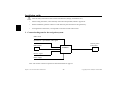
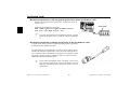
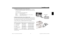
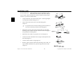
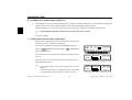
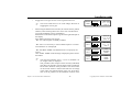
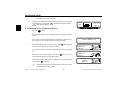
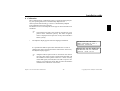
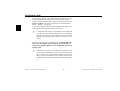
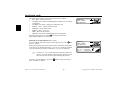
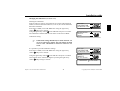
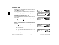
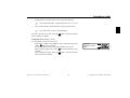
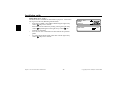
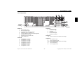
,QVWDOODWLRQJXLGH 1. 2. 3. 4. 5. ”Symbols used in the installation guide” on page 25 ”Connection diagram for the navigation system” on page 26 ”Installation of the GPS antenna” on page 27 ”Connecting the reverse signal” on page 29 ”Connecting the speed signal (GAL) for the speedometer / speedometer cable” on page 29 6. ”Installing and commissioning Traffic Pro” on page 34 7. ”Using GPS for the first time, and sensors” on page 34 8. ”Installation of the Navigation Software” on page 36 9. ”Calibration” on page 37 10. ”Service Mode” on page 39 11. ”Connections” on page 47 6\PEROVXVHGLQWKHLQVWDOODWLRQJXLGH G denotes instructions which are important for your safety and the safety of others. denotes instructions which are important for the installation and function of the unit. 6DIHW\DQGLQVWDOODWLRQLQVWUXFWLRQV The installation of TrafficPro should only be carried out by a specialist. • Disconnect the vehicle battery before installation of the unit. Subject to correction and technical modifications 25 Copyright by Becker GmbH, D-76303 Karlsbad ,QVWDOODWLRQJXLGH G Note the safety instructions of the vehicle manufacturer (airbags, immobilisers etc.). • When routing the cables, ensure that they cannot become jammed, kinked or ripped out. • Before installation, park the vehicle in a safe and level place and remove the ignition key. • If using branch connections, it is important to note the relevant cable section. &RQQHFWLRQGLDJUDPIRUWKHQDYLJDWLRQV\VWHP Radio aerial Speedometer / speedometer cable signal Sound system / loudspeaker GPS antenna 7UDIILF3UR Reverse signal Power supply Note: The various connection options are described in detail on page 47. Subject to correction and technical modifications 26 Copyright by Becker GmbH, D-76303 Karlsbad ,QVWDOODWLRQJXLGH ,QVWDOODWLRQRIWKH*36DQWHQQD G People with pacemakers should avoid physical contact with the magnetic antenna and should not carry the antenna on their person, as this may affect the function of the pacemaker. Keep the magnetic antenna away from data storage media (disks, credit cards, magnetic cards etc.) and electronic and precision engineering equipment, as this may cause data to be deleted. Do not use the antenna in areas at risk of explosion. It is important to secure the antenna so that it cannot become detached in a collision or sudden brake manoeuvre. 3RVVLEOHLQVWDOODWLRQSRVLWLRQV 2XWVLGHWKHYHKLFOH a. Attach the antenna to a flat, pre-washed metal surface. b. Then guide the antenna cable into the vehicle interior. G The maximum vehicle speed for the antenna if magnetically attached is 180 km/h. The antenna must be removed or specially secured at higher speeds. The antenna is not suitable for car-wash facilities. ,QVLGHWKHYHKLFOH ) ) The antenna can only be installed on a non-metallised windscreen. When selecting the installation position, ensure that the antenna has a clear view of all directions, and that it is not covered by the windscreen wipers. Obstructions caused by the bonnet, window crossbeams and roof should be avoided as far as possible. Subject to correction and technical modifications 27 Copyright by Becker GmbH, D-76303 Karlsbad ,QVWDOODWLRQJXLGH a. Secure the antenna to the base plate (1) with magnets. b. Remove protective strip from top of adhesive tape (2) and stick to the centre of the base plate underside. c. Remove protective strip from bottom of adhesive tape (2) and stick the antenna and base plate onto the vehicle console beneath the windscreen at the installation position. ) GPS reception can be affected by screens with screen antenna, windscreen heating or thermally insulated screens. Some thermally insulated screens are coated with titanium or silver oxide. Installation of the GPS antenna in the vehicle interior can considerably impair the function of the navigation system. Subject to correction and technical modifications 28 Copyright by Becker GmbH, D-76303 Karlsbad ,QVWDOODWLRQJXLGH &RQQHFWLQJWKHUHYHUVHVLJQDO ,IWKHVZLWFKRQWKHJHDUER[RUVKLIWOLQNDJHLVDFFHVVLEOH • Connect a separate lead to the activated contact. Connect the lead to socket A pin 2. /RZOHYHO HDUWKKLJKOHYHO99 $ ,IWKHVZLWFKLVQRWDFFHVVLEOH • Check which lead is routed to the reversing lamp. Then, if necessary, remove the inner cover for the reversing light. Connect a separate lead to the activated lead of the reversing lamp and connect to socket A pin 2. 5HYHUVH VLJQDO &RQQHFWLQJWKHVSHHGVLJQDO*$/IRUWKHVSHHGRPHWHUVSHHGRPHWHUFDEOH (OHFWURQLFVSHHGRPHWHU • Remove the signal from the speedometer, extend and connect to socket A pin 1. ) • Depending on the vehicle equipment, the lead for the GAL signal is usually connected to the DIN - ISO plug of the car radio. The assignment of the DIN - ISO plug may vary depending on the vehicle type. *$/VLJQDO $ Minimum requirement for the signal: +]N+]VTXDUHZDYHVLJQDOQRLQGXFWLYHVHQVRU /RZOHYHO9KLJKOHYHO99 ) If you do not know the exact installation position / location of the speed signal, please consult the vehicle manufacturer. Subject to correction and technical modifications 29 Copyright by Becker GmbH, D-76303 Karlsbad ,QVWDOODWLRQJXLGH 0HFKDQLFDOVSHHGRPHWHUZLWKLQWHJUDWHGVSHHGVHQVRULQWKHVSHHGRPHWHUFDEOH • Remove the signal from the speed sensor, extend and connect to socket A pin 1. • Minimum requirement for the signal: +]N+]VTXDUHZDYHVLJQDOQRLQGXFWLYHVHQVRU /RZOHYHO9KLJKOHYHO99 ) *$/VLJQDO $ If you do not know the exact installation position / location of the speed signal, please consult the vehicle manufacturer. 0HFKDQLFDOVSHHGRPHWHUZLWKRXWVSHHGVHQVRULQWKHVSHHGRPHWHUFDEOH A speed sensor which generates a digital, speed-dependent signal must be installed in the speedometer cable. The VDO adapter 2152.30300000 or a vehicle-specific adapter which satisfies the minimum requirements can be used. The VDO speed sensor is suitable for direct installation on the gearbox (no further installation parts required) or in the speedometer cable (in conjunction with additional universal installation parts). ) If the sealed speedometer cable is released, a correct display cannot be guaranteed. Incorrect installation leads to improper functioning of the navigation system or of the speedometer. Subject to correction and technical modifications 30 Copyright by Becker GmbH, D-76303 Karlsbad ,QVWDOODWLRQJXLGH ,QVWDOOLQJWKHVSHHGVHQVRUGLUHFWO\RQWKHJHDUER[ • Release the speedometer cable and screw speed sensor onto gearbox. Screw released speedometer cable onto the speed sensor and connect the wires. :LUHFRQQHFWLRQVIRUWKHVSHHGVHQVRU Brown - earth (terminal 31) Black - power supply (terminal 15), 9 - 16V, 30 mA Blue/red - signal for socket A pin 1 ,QVWDOOLQJWKHVSHHGVHQVRULQWKHVSHHGRPHWHUFDEOH In order to install the speed sensor, the speedometer drive cable must be cut in one even piece for insertion of the speed sensor. When removing the speedometer cable from the vehicle, ensure that the location of the evenly running piece is established and marked accordingly. Installation is illustrated without reference to any specific vehicle. In addition to the sensor, the following VDO universal parts are required: 1 x connecting piece 1040 1300 025 (VDO part number) 2 x knurled nuts1 040 1000 003 (VDO part number) 2 x hose sleeves 1040 1000 031 (VDO part number) 2 x dogs 1 040 1000 049 (VDO part number) 2 x friction washers 1040 0900 003 300 (VDO part number) 2 x fuel washers 4.0 KN07.0570.18 (VDO part number) 2 x washers KN11.1904.122 (VDO part number) An appropriate, complete kit from VDO (part number X 39397106191) can also be used. Subject to correction and technical modifications 31 *$/VLJQDO $ )LJXUH Copyright by Becker GmbH, D-76303 Karlsbad ,QVWDOODWLRQJXLGH Recommended tool: Cable installation tool for speedometer cables from VDO, order number: 1999.10.13.000.110 If you require vehicle-specific parts, please consult the vehicle manufacturer or your nearest VDO branch. • Using a metal saw, saw into the cable approx. 1 mm at right angles to the profile and break off (Figure 3). • Then cut the cable in the centre with side-cutting pliers (Figure 4). ) • For protective hoses with wire netting, the hose and flex cable can be cut directly with the side-cutting pliers. Shorten the protective hose again at both ends up to the plastic sheathing. Check whether the ends of the flex cable still engage in the speedometer and the gearbox. • Shorten the inner cable to a projection of 13 mm (Figure 5). • Connect the union nut and hose sleeve (Figure 6) and push onto the hose ends (Figure 7). • Connect friction washer to dog (Figure 8). • Remove grease from flex cable and connect dog to flex cable. Using a suitable installation tool, press the dog onto the flex cable (Figure 9). Subject to correction and technical modifications 32 )LJXUH )LJXUH )LJXUH )LJXUH )LJXUH )LJXUH Copyright by Becker GmbH, D-76303 Karlsbad ,QVWDOODWLRQJXLGH ) When pressing in, ensure that the dog is securely positioned and that it runs smoothly. • Pull the hose sleeve and nut as far as possible in the direction of the dog, to achieve approx. 1-2 mm play (Figure 10). Slightly squeeze the hose sleeve with pliers. Wrap with isolating tape to secure (Figure 11). • Screw the connecting piece and the speed sensor into the cable (Figure 12). • Connect speed sensor using the extension cable from VDO (part number: 2152.90 30 0100). :LUHFRQQHFWLRQVIRUWKHVSHHGVHQVRU Brown - earth (terminal 31) Black - power supply (terminal 15), 9 - 16V, 30 mA Blue/red - signal for socket A pin 1 Subject to correction and technical modifications 33 )LJXUH )LJXUH )LJXUH )LJXUH Copyright by Becker GmbH, D-76303 Karlsbad ,QVWDOODWLRQJXLGH ,QVWDOOLQJDQGFRPPLVVLRQLQJ7UDIILF3UR • This navigation system has an integrated universal bracket for DIN installation slots. An installation frame is not required. The unit is inserted into the installation slot and secured with the slides supplied. Further information is given in the operation guide in the chapter, "Installation and removal instructions". ) • 7KHLQVWDOODWLRQDQJOHRIWKHXQLWPXVWQRWH[FHHGWRYHUWLFDO Connect the battery. 8VLQJ*36IRUWKHILUVWWLPHDQGVHQVRUV • Switch on the vehicle ignition to start using GPS for the first time and for the sensor test. Switch on Traffic Pro. Enter code (see the operation guide for a detailed description). • Press the multifunction button and the button simultaneously. • This calls up the menu for the initial GPS start-up and for the sensor test. • multifunction $! P Y 5; +; ,. 79 7,,+ P P >9 SM 09,*;065 P $! P P VVV P Move the vehicle several metres forwards or backwards for the speed signal function test. ) The number under 7,,+ must change (even at a low speed). The number under 7,,+ should not increase when idling or pressing the accelerator when the vehicle is parked. Subject to correction and technical modifications 34 7,,+ VMN 09,*;065 $! P P P Copyright by Becker GmbH, D-76303 Karlsbad ,QVWDOODWLRQJXLGH • Engage the reverse gear for the reverse signal function test. ) • 7,,+ The arrows under 09,*;065 must change direction on engaging the reverse gear. When using the GPS for the first time, the vehicle must be parked outdoors, while ensuring that it has a clear view in all directions (not in the immediate vicinity of buildings). Information on the GPS reception is given in the right-hand part of the display. Four different messages may appear: - : GPS reception is already available. 09,*;065 VVV P 7,,+ - ! : The GPS antenna is not properly connected. - " : If this message is displayed, please contact the hotline. ) You must wait until , P (or P ) and P (or a higher value) is displayed. This procedure (first reception of the necessary GPS data) may take a few minutes. The unit must remain switched on for the entire duration of this procedure. The vehicle must not be moved. If after 5 minutes there has been no change in the values, the parked position (clear view in all directions as far as possible) or the installation location of the Subject to correction and technical modifications 35 09,*;065 VMN 09,*;065 $! P P VMN P 7,,+ 09,*;065 ! VMN 7,,+ VMN P P P 7,,+ - $! : It is necessary to wait for GPS reception. You must wait until is displayed. $! P P 09,*;065 " Copyright by Becker GmbH, D-76303 Karlsbad ,QVWDOODWLRQJXLGH GPS antenna must be checked. • The menu for initial GPS start-up and for the sensor test is quit by simultaneously pressing the multifunction button and the multifunction button. 7,,+ 09,*;065 VMN P P P ,QVWDOODWLRQRIWKH1DYLJDWLRQ6RIWZDUH 1DY • Press the button. • Insert the Navigation CD to install the software for the navigation system. • After the navigation software has been installed, the adjacent display appears. The language selection is then requested. • Select the language using the right rotary control selection is accepted by pressing the control. . The voice is ac- The adjacent display appears after installation. Then press the right rotary control to confirm. ) #! . The language You can choose either a male or a female voice for some languages. Select the voice using the right rotary control cepted and installed by pressing the control. #! !#!B M " The language selection can be changed at a later time, as described in the operating guide. Subject to correction and technical modifications 36 Copyright by Becker GmbH, D-76303 Karlsbad ,QVWDOODWLRQJXLGH &DOLEUDWLRQ After commissioning, a calibration journey is required. During the journey, the speed signal (GAL) is automatically adapted to the vehicle-specific data and the gyro sensor is automatically adapted to the installation position of the unit. The distance to be covered depends on the type of vehicle and the local conditions. ) • The navigation system is only ready for operation on completion of the calibration journey. The main navigation menu is displayed. Final precision is only achieved after a further journey. The adjacent display appears after the language installation. ! !! $PN&PN !P PYPY It is possible that GPS reception has deteriorated as a result of changing the vehicle position and due to obstructions. In this case, the adjacent display appears. ) $! !B !! YYP\% Adequate GPS reception must be ensured for the calibration ride. This means at least 2-D FIX. With GPS FIX 3-D the calibration will be quicker. However: a lower accuracy of the GPS signal (2-D FIX) does not lead to a poorer calibration, but instead will mean that the time and distance needed for the calibration will increase. Subject to correction and technical modifications 37 Copyright by Becker GmbH, D-76303 Karlsbad ,QVWDOODWLRQJXLGH If, even after a relatively long period of time, the display with the request ! !! does not appear, then you should check the GPS reception conditions again (as under Service Mode in the Section ”Function test of GPS antenna ( )” on page 40). As soon as the display with the request ! !! appears, the calibration ride can be started. ) • A calibration ride can also be performed in a non-digitised area. The insertion of the Navigation CD is not absolutely necessary after the navigation software has been installed. Without the Navigation CD inserted, no location is displayed. The basic requirement for a calibration ride is: GULYLQJ PHWUHVLQDVWUDLJKWOLQHWKHQWXUQLQJE\DWOHDVWGHJUHHV DQGWKHQGULYLQJPHWUHVLQDVWUDLJKWOLQHDJDLQDQG WXUQLQJDJDLQ ) The direction you turn is of no significance. If these conditions cannot be fulfilled due to the road or the fact that you do not always have optimum GPS reception, this will not lead to a poorer calibration, but will simply mean the time and distance necessary for the calibration ride will be longer. Subject to correction and technical modifications 38 Copyright by Becker GmbH, D-76303 Karlsbad ,QVWDOODWLRQJXLGH ) If the unit is switched off during the calibration ride, language installation is requested when the unit is switched on again. Reinstallation can be skipped by pressing the 1DY button. !Y& • • Calibration has been completed successfully if the main navigation menu is displayed. YYY For correct navigation on routes with time-dependent traffic guidance, the time should be set correctly as described under "System settings" in the operation guide. 6HUYLFH0RGH In Service Mode, various functions can be checked in detail and the calibration can be modified. • • • • Switch on the unit (see operation guide). Enter code (see operation guide). If the unit has already been calibrated, select the main navigation menu by pressing the 1DY button. If the unit has not been calibrated, proceed as described in the next point but one. Press the 1DY button again to access the system settings. Press and hold the multifunction buttons. Then press the multifunction button. This calls up the Service Mode. Subject to correction and technical modifications 39 !Y& YYY !F Copyright by Becker GmbH, D-76303 Karlsbad ,QVWDOODWLRQJXLGH The following functions can be selected in the Service Mode: • - GPS function test • ! - function for deleting the calibration or for setting a calibration • ! - display for calibration ride • "! ! - internal component test • - sensor function test • ! ! - voice test • - demo mode selection • # - the status of the Navigation CD is displayed By turning the right rotary control , select the desired entry (large letters) and press to confirm. )XQFWLRQWHVWRI*36DQWHQQD In Service Mode, select S with the right rotary control and press to confirm. If functioning properly and with GPS reception, the number of satellites received (e.g. ), the date and time (e.g. YYPP ) and the type of positioning currently possible %P (e.g. ) are displayed. ) # ! # ! PPPP %%P Y&P At least % is required for quick and successful calibration. A certain amount of time may be required to reach this value (do not move the vehicle during this period). In order to quit the GPS test, press the back to the Service Mode. Subject to correction and technical modifications 1DY button. The unit switches 40 Copyright by Becker GmbH, D-76303 Karlsbad ,QVWDOODWLRQJXLGH &KDQJLQJWKHFDOLEUDWLRQ! Deleting the calibration: If the navigation system is removed from one vehicle and installed in another, it must be calibrated. However, to do so, the current calibration data must be deleted. In the Service Mode, select ! using the right rotary control and press to confirm. Using the right rotary control select ! and press to confirm. The calibration is deleted and the unit returns to the Service Mode. ! !! & Calibration setting: ) &DOLEUDWLRQVHWWLQJVVKRXOGRQO\EHPDGHZKHQWKHYDO XHVWREHHQWHUHGDUHNQRZQ7KHXQLWFDQQRWSHUIRUP FRUUHFW URXWH FDOFXODWLRQV LI LQFRUUHFW YDOXHV DUH HQ WHUHG It is possible to provide calibration settings. In the Service Mode, select ! using the right rotary control and press to confirm. Using the right rotary control select & and press to confirm. Unit rotation can be selected in degrees by turning the right rotary control and pressing to confirm. ! ! !! '!"!!! Subject to correction and technical modifications 41 Copyright by Becker GmbH, D-76303 Karlsbad ,QVWDOODWLRQJXLGH ) Unit rotation corresponds to horizontal rotation. A positive value means rotation of the front of the unit towards the driver (LHD). The unit inclination can now be selected in degrees by turning the right rotary control and pressing to confirm. ) "!! Unit inclination corresponds to vertical inclination. A positive value means upward inclination of the front of the unit. The number of wheel impulses per wheel revolution (if known) can then be selected by turning the right rotary control and pressing to confirm. ) $" "$ If the number of wheel impulses per wheel revolution is not known, "$ must be selected. It is then not possible to enter tyre data. The previously entered data is displayed once more. If the data entered is correct, press the right rotary control . If correction is necessary, select & by turning the right rotary control and press to confirm. The values can then be re-entered. E V E N Q E P T Once the previously entered data has been confirmed, the tyre data can be entered or self-calibration can be started. To enter the tyre data, select "!!&#" by turning the right rotary control and press to confirm. D Subject to correction and technical modifications 42 & "!!&#" Copyright by Becker GmbH, D-76303 Karlsbad ,QVWDOODWLRQJXLGH Enter the correct tyre size using the right rotary control and confirm the entry by pressing for more than 2 seconds. "!!& P !& 'TTTFTTTFTTT ) The letter "R" cannot be entered. 3 numbers must be entered before and after the slashes. Insert a "0" for any missing numbers. Example: Specification in vehicle registration papers: 185/55R15 81T Input into unit: 185/055/015 Then select between $!&! and " !&! by turning the right rotary control to enter the approximate tread depth value. Press the right rotary control to confirm the selection. The previously entered data is displayed once more. If the data entered is correct, press the right rotary control . If correction is necessary, select & by turning the right rotary control and press to confirm. The values can then be re-entered. After confirming the tyre data or the previously confirmed point !! ! , the adjacent display appears. After a short time, the unit switches to the main navigation menu or the calibration ride is requested. ) GLQH " !&!GLJH MTQYVQQYVMQN & "! The unit is now in calibration status 2. Absolute precision is, however, only achieved as of calibration status 3. Subject to correction and technical modifications 43 Copyright by Becker GmbH, D-76303 Karlsbad ,QVWDOODWLRQJXLGH 6WDWXVRIFDOLEUDWLRQULGH! In the Service Mode, select ! using the right rotary control and press to confirm. The calibration status (e.g. !!P ) and the type of positioning (e.g. ) are displayed. After completing calibration, the street in which you are currently driving is displayed (provided that it is digitised) instead of $ and #Y . 7HVWLQJWKHV\VWHPFRPSRQHQWV"! ! A test program automatically tests the internal components of the navigation system. In the Service Mode, select "! ! using the right rotary control and press to confirm. If is displayed, press the 1DY button. The unit switches back to the Service Mode. )XQFWLRQ WHVW RI WKH *$/ VLJQDO UHYHUVH VLJQDO LQWHUQDO VHQVRUV • In the Service Mode, select using the right rotary control and press to confirm. ! "! ! !!PS% !! PYPY ! "! ! ! ! • Move the vehicle several metres forwards or backwards for the GAL signal function test. ) The number after $P should increase (even at a low speed). The number after $P should not increase if idling or pressing the accelerator when the vehicle is parked. Subject to correction and technical modifications 44 $P#YP &P %PS &PS Copyright by Becker GmbH, D-76303 Karlsbad ,QVWDOODWLRQJXLGH • Engage the reverse gear for the reverse signal function test. ) • The number after #YP should jump from to ( to ). Drive round a bend to test the function of the internal sensors. ) The values after %P and &P should change. In order to quit the sensor test, press the back to the Service Mode. 1DY button. The unit switches 7HVWLQJWKHYRLFH ! ! A test program is used to test the voice. • In the Service Mode, select ! ! using the right rotary control and press to confirm. The announcement "Please insert Navigation CD" is given. By pressing the right rotary control , the announcement can be repeated. After completing the test, press the 1DY button. The unit switches back to the Service Mode. Subject to correction and technical modifications 45 Copyright by Becker GmbH, D-76303 Karlsbad ,QVWDOODWLRQJXLGH 'HPR0RGH The demo mode is intended for demonstration purposes. A fixed location is given to the unit (Hamburg Werderstaße). • In the Service Mode, select S using the right rotary control and press to confirm. Select between and by briefly pressing the right rotary control . By holding down the right rotary control , the selection is confirmed. • You can now enter a destination as described in the operation guide. • To switch off the demo mode, select with the right rotary control and press to confirm. Subject to correction and technical modifications 46 ! ! # S F Copyright by Becker GmbH, D-76303 Karlsbad ,QVWDOODWLRQJXLGH &RQQHFWLRQV C1 C2 C3 B $QWHQQD EXVKLQJ A *36 DQWHQQD 6RFNHW& &RQQHFWLRQLQVWUXFWLRQV 6RFNHW$ 1 2 3 4 5 6 7 8 1 2 3 4 5 6 Speed signal (GAL) Reversing lamp signal Telephone mute / clearing function Permanent positive (terminal 30) Control output for automatic antenna/amplifier Illumination (terminal 58) Switched positive (terminal 15) Earth (terminal 31) 6RFNHW& 7-12 6RFNHW% 1 2 3 4 5 6 7 8 Special connection for Becker CD changer 6RFNHW& Loudspeaker rear right + Loudspeaker rear right Loudspeaker front right + Loudspeaker front right Loudspeaker front left + Loudspeaker front left Loudspeaker rear left + Loudspeaker rear left - Subject to correction and technical modifications LineOut rear left LineOut rear right AF earth LineOut front left LineOut front right Subwoofer LineOut 13 14 15-17 18 19 20 47 AF telephone input Earth - telephone input Special connection for Becker CD changer CD AF earth (AUX) CD AF left (AUX) CD AF right (AUX) Copyright by Becker GmbH, D-76303 Karlsbad