1
026-1610 Rev 10 06-APR-2010
E2 Installation and Operation Manual for RX Refrigeration,
BX HVAC, and CX Convenience Store Controllers
3240 Town Point Drive NW, Suite 100
Kennesaw, GA 30144, USA
Phone 770-425-2724
Fax 770-425-9319
ALL RIGHTS RESERVED
The information contained in this manual has been carefully checked and is believed
to be accurate. However, Computer Process Controls, Inc. assumes no responsibility
for any inaccuracies that may be contained herein. In no event will Computer Process
Controls, Inc. be liable for any direct, indirect, special, incidental, or consequential
damages resulting from any defect or omission in this manual, even if advised of the
possibility of such damages. In the interest of continued product development, Computer Process Controls, Inc. reserves the right to make improvements to this manual,
and the products described herein, at any time without notice or obligation.
FCC COMPLIANCE NOTICE
This device complies with Part 15 of the FCC Rules. Operation is subject to the following two conditions: (1) this device may not cause harmful interference, and (2) this
device must accept any interference received, including interference that may cause
undesired operation.
CE COMPLIANCE NOTICE
Class A Product Information for Einstein, E2 Controllers:
The Retail Solutions Einstein and E2 controllers are Class A products. In a domestic
environment this product may cause radio interference in which case the user may be
required to take adequate measures. This covers:
•
All Einstein family product types: RX - Refrigeration Controller
(830-xxxx), BX - Building/HVAC Controller (831-xxxx), and all version models: (300, 400, 500).
•
All E2 family product types: RX - Refrigeration Controller (834-xxxx),
BX - Building/HVAC Controller (835-xxxx), CX- Convenience Store
Controller (836-xxxx), and all version models: (300, 400, 500).
Table of Contents
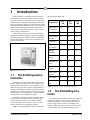
1 INTRODUCTION...................................................................................................................................................... 1-1
1.1 THE E2 REFRIGERATION CONTROLLER .....................................................................................................................
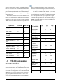
1.2 THE E2 BUILDING CONTROLLER ...............................................................................................................................
1.3 THE E2 CONVENIENCE STORE CONTROLLER ............................................................................................................
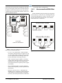
1.4 NETWORKING OVERVIEW ..........................................................................................................................................
1.4.1 E2 I/O Network ..................................................................................................................................................
1.4.2 The E2 Echelon Lonworks Network...................................................................................................................
1.4.3 Interconnection With Other E2s ........................................................................................................................
1.5 DOCUMENTATION OVERVIEW ...................................................................................................................................
1.6 ON-LINE HELP SYSTEM OVERVIEW ..........................................................................................................................
1.7 SOFTWARE LICENSING ...............................................................................................................................................
1-1
1-1
1-2
1-3
1-3
1-3
1-4
1-5
1-6
1-6
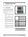
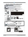
2 HARDWARE OVERVIEW...................................................................................................................................... 2-1
2.1 E2 HARDWARE ..........................................................................................................................................................
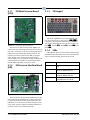
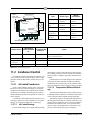
2.1.1 E2 Main Processor Board (CPU)......................................................................................................................
2.1.2 E2 Processor Interface Board (PIB)..................................................................................................................
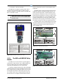
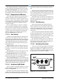
2.1.3 E2 Keypad ..........................................................................................................................................................
2.1.4 LEDs...................................................................................................................................................................
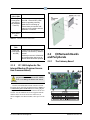
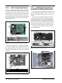
2.1.5 PC-104 Peripherals: The Internal Modem (Previous Generation Processor Board).......................................
2.2 I/O NETWORK BOARDS AND PERIPHERALS ...............................................................................................................
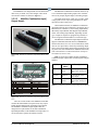
2.2.1 The Gateway Board ...........................................................................................................................................
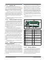
2.2.2 MultiFlex Boards ...............................................................................................................................................
2.2.2.1
2.2.2.2
2.2.2.3
2.2.2.4
2.2.2.5
2.2.2.6
2-1
2-2
2-2
2-2
2-2
2-3
2-3
2-3
2-4
MultiFlex 16 Input Board ........................................................................................................................................ 2-4
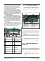
MultiFlex Combination Input/Output Boards.......................................................................................................... 2-5
MultiFlex CUB ........................................................................................................................................................ 2-7
MultiFlex RTU (BX and CX Only) ......................................................................................................................... 2-7
MultiFlex Rooftop Control Board (RCB) (BX and CX Only) ................................................................................ 2-7
MultiFlex PAK Board.............................................................................................................................................. 2-7
2.2.3 The MultiFlex ESR Board .................................................................................................................................. 2-8
2.2.4 Hand-held Terminal (P/N 814-3110)................................................................................................................. 2-8
2.2.5 The 8RO and 8ROSMT Relay Boards................................................................................................................ 2-9
2.2.6 4AO Analog Output Board............................................................................................................................... 2-10
2.2.7 8DO Digital Output Board and PMAC II Anti-Sweat Controller ................................................................... 2-10
2.3 ECHELON NETWORK BOARDS AND PERIPHERALS ................................................................................................... 2-11
2.3.1 The 16AIe (Discontinued) ................................................................................................................................ 2-11
2.3.2 The 8ROe (Discontinued)................................................................................................................................. 2-11
2.3.3 EC-2s................................................................................................................................................................ 2-11
2.3.4 CC-100 Case Controllers and CS-100 Case Circuit Controllers.................................................................... 2-12
2.3.5 The ESR8 (Discontinued)................................................................................................................................. 2-12
2.3.6 TD3 Temperature Display ............................................................................................................................... 2-13
2.3.7 Facility Status Display (FSD) .......................................................................................................................... 2-13
3 MOUNTING............................................................................................................................................................... 3-1
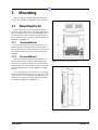
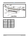
3.1 MOUNTING THE E2 ....................................................................................................................................................
3.1.1 Standard Mount..................................................................................................................................................
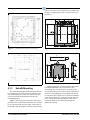
3.1.2 Recessed Mount..................................................................................................................................................
3.1.3 Retrofit Mounting...............................................................................................................................................
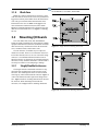
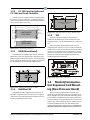
3.1.4 Blank Face .........................................................................................................................................................
3.2 MOUNTING I/O BOARDS ............................................................................................................................................
E2 RX/BX/CX I&O Manual
3-1
3-1
3-1
3-2
3-3
3-3
Table of Contents • v
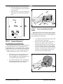
3.2.1 Single/Double Enclosures .................................................................................................................................
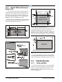
3.2.2 Boards Without Enclosures (Snap Track)..........................................................................................................
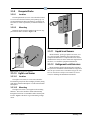
3.3 ECHELON DEVICES ....................................................................................................................................................
3.3.1 16AIe and 8ROe .................................................................................................................................................
3.3.2 CC-100 Case Controller and CS-100 Case Circuit Controller .........................................................................
3.3.3 ESR8 (Discontinued) ..........................................................................................................................................
3.3.4 MultiFlex ESR ....................................................................................................................................................
3.3.5 TD3.....................................................................................................................................................................
3.4 MODEM/COMMUNICATION EXPANSION CARD MOUNTING (NEW PROCESSOR BOARD) ...........................................
3.4.1 Mounting PC-104 Cards in E2 (Previous Generation Processor Board) .........................................................
3-3
3-4
3-4
3-4
3-5
3-5
3-5
3-5
3-5
3-6
3.4.1.1 The Internal Modem ................................................................................................................................................ 3-6
3.4.2 Two-Channel and Four-Channel Repeaters ...................................................................................................... 3-6
3.4.2.1 Mounting Repeaters Overview ................................................................................................................................ 3-6
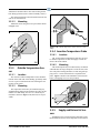
3.4.2.2 Mounting the Two-Channel Repeater...................................................................................................................... 3-6
3.4.2.3 Mounting the Four-Channel Repeater ..................................................................................................................... 3-7
3.5 SENSORS AND TRANSDUCERS .................................................................................................................................... 3-7
3.5.1 Pressure Transducers......................................................................................................................................... 3-7
3.5.1.1 Mounting.................................................................................................................................................................. 3-7
3.5.2 Inside Temperature Sensor................................................................................................................................. 3-7
3.5.2.1 Location ................................................................................................................................................................... 3-7
3.5.2.2 Mounting.................................................................................................................................................................. 3-8
3.5.3 Outside Temperature Sensor.............................................................................................................................. 3-8
3.5.3.1 Location ................................................................................................................................................................... 3-8
3.5.3.2 Mounting.................................................................................................................................................................. 3-8
3.5.4 Insertion Temperature Probe ............................................................................................................................. 3-8
3.5.4.1 Location ................................................................................................................................................................... 3-8
3.5.4.2 Mounting.................................................................................................................................................................. 3-8
3.5.5 Supply and Return Air Sensors........................................................................................................................... 3-8
3.5.6 Refrigeration System Temperature Probes and Sensors.................................................................................... 3-9
3.5.6.1 Location ................................................................................................................................................................... 3-9
3.5.6.2 Mounting Bullet and Pipe Mount Sensors ............................................................................................................... 3-9
3.5.7 Product Temperature Probes ............................................................................................................................. 3-9
3.5.8 Humidity Sensors and Humidistats .................................................................................................................... 3-9
3.5.8.1 Indoor RH Sensor .................................................................................................................................................... 3-9
3.5.8.2 Outdoor RH Sensors .............................................................................................................................................. 3-10
3.5.8.3 Duct-mounted Insertion RH Probe ........................................................................................................................ 3-10
3.5.9 Dewpoint Probe................................................................................................................................................ 3-11
3.5.9.1 Location ................................................................................................................................................................. 3-11
3.5.9.2 Mounting................................................................................................................................................................ 3-11
3.5.10 Light Level Sensor.......................................................................................................................................... 3-11
3.5.10.1 Location ............................................................................................................................................................... 3-11
3.5.10.2 Mounting.............................................................................................................................................................. 3-11
3.5.11 Liquid Level Sensors ...................................................................................................................................... 3-11
3.5.12 Refrigerant Leak Detectors ............................................................................................................................ 3-11
4 E2 HARDWARE SETUP .......................................................................................................................................... 4-1
4.1 SETTING UP THE E2 ...................................................................................................................................................
4.1.1 Enclosure............................................................................................................................................................
4.1.2 Main Processor Board .......................................................................................................................................
4.1.3 Main Processor Board (Previous Version)........................................................................................................
4.1.4 Power Interface Board .......................................................................................................................................
4.2 POWERING THE E2 .....................................................................................................................................................
4.2.1 RS485 Ports........................................................................................................................................................
4.2.2 RS485 Jumpers...................................................................................................................................................
4.2.3 Echelon Network Connect..................................................................................................................................
vi • Table of Contents
4-1
4-1
4-1
4-2
4-2
4-2
4-2
4-2
4-2
026-1610 Rev 10 06-APR-2010
4.2.4 Echelon Jumpers ................................................................................................................................................
4.3 ADD-ON E2 PERIPHERALS.........................................................................................................................................
4.3.1 Plug-In Echelon Card (P/N 537-4860) with mounting screw (P/N 101-4201) .................................................
4.3.2 Modem/Communication Expansion Card (New Processor Board)...................................................................
4.3.3 Plug-In Modem Card (P/N 537-4870) with mounting screws
(P/N 101-4038) and standoffs (P/N 107-9440) (Previous Generation Processor Board) ...........................................
4.3.4 Plug-In Digital I/O Network Card (P/N 537-4880)...........................................................................................
4-2
4-2
4-3
4-3
4-4
4-4
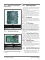
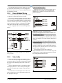
4.3.4.1 LEDs ........................................................................................................................................................................ 4-4
4.3.5 E2 RS485 Port Card (P/N 537-4890) ................................................................................................................ 4-4
4.3.5.1 LEDs ........................................................................................................................................................................ 4-4
4.3.6 Plug-In Four-Channel Internal Repeater ..........................................................................................................
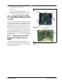
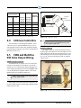
4.4 BATTERY TESTING AND REPLACEMENT ....................................................................................................................
4.4.1 Low Battery Notification....................................................................................................................................
4.4.2 The Battery Enable Switch.................................................................................................................................
4.4.3 Battery Test ........................................................................................................................................................
4.4.4 Battery Replacement - Qualified Technicians Only...........................................................................................
4-5
4-5
4-5
4-5
4-5
4-5
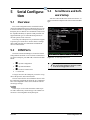
5 SERIAL CONFIGURATION ................................................................................................................................... 5-1
5.1 OVERVIEW ................................................................................................................................................................. 5-1
5.2 COM PORTS .............................................................................................................................................................. 5-1
5.3 SERIAL DEVICE AND SOFTWARE SETUP .................................................................................................................... 5-1
6 THE RS485 NETWORK AND HARDWARE SETUP .......................................................................................... 6-1
6.1 THE I/O NETWORK .................................................................................................................................................... 6-1
6.1.1 I/O Board Names and Terminology ................................................................................................................... 6-1
6.1.2 MultiFlex-Plus (+) Board .................................................................................................................................. 6-2
6.1.2.1 Board Designation ................................................................................................................................................... 6-2
6.1.2.2 Board Calculations................................................................................................................................................... 6-2
6.1.3
6.1.4
6.1.5
6.1.6
6.1.7
6.1.8
6.1.9
Wiring Types ......................................................................................................................................................
The I/O Network Structure (Daisy Chains)........................................................................................................
Network Noise Minimization..............................................................................................................................
Network ID Numbers (Board Numbers) ............................................................................................................
Setting the Baud Rate.........................................................................................................................................
Setting the Terminating and Biasing Jumpers ...................................................................................................
Powering the I/O Boards ...................................................................................................................................
6-2
6-2
6-2
6-3
6-3
6-4
6-4
6.1.9.1 Wiring Types ........................................................................................................................................................... 6-5
6.1.10 Board Installation ............................................................................................................................................
6.2 LENNOX IMC ROOFTOP UNIT CONTROLLERS ...........................................................................................................
6.3 CONTROL TECHNIQUES DRIVE (VSD) ......................................................................................................................
6.4 ECT MODBUS .........................................................................................................................................................
6.4.1 Copeland ISD Compressors...............................................................................................................................
6-5
6-5
6-6
6-6
6-6
7 E2 ETHERNET PEER COMMUNICATIONS ...................................................................................................... 7-1
7.1 ETHERNET IP CONFIGURATIONS ...............................................................................................................................
7.2 HARDWARE SPECIFICATIONS .....................................................................................................................................
7.2.1 Components........................................................................................................................................................
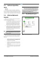
7.3 SOFTWARE SPECIFICATIONS ......................................................................................................................................
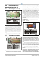
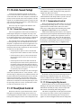
7.4 ETHERNET NETWORK LAYOUTS ................................................................................................................................
7.4.1 Closed Network Layout......................................................................................................................................
7.4.2 Open Network Layout ........................................................................................................................................
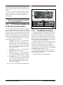
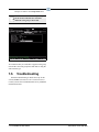
7.5 SOFTWARE SETUP ......................................................................................................................................................
7.6 TROUBLESHOOTING ...................................................................................................................................................
7-1
7-1
7-1
7-2
7-2
7-2
7-3
7-3
7-4
8 ECHELON NETWORK AND HARDWARE SETUP........................................................................................... 8-1
E2 RX/BX/CX I&O Manual
Table of Contents • vii
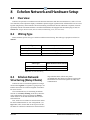
8.1 OVERVIEW .................................................................................................................................................................
8.2 WIRING TYPE .............................................................................................................................................................
8.3 ECHELON NETWORK STRUCTURING (DAISY-CHAINS) ..............................................................................................
8.3.1 Maximum Number of Echelon Devices ..............................................................................................................
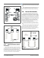
8.4 DEVICE TERMINATION ...............................................................................................................................................
8.4.1 Using a Termination Block (P/N 535-2715) to Terminate a Daisy Chain.........................................................
8.5 WIRE RESTRICTIONS ..................................................................................................................................................
8.6 INSTALLING ECHELON DEVICES ................................................................................................................................
8.6.1 Powering Echelon Devices.................................................................................................................................
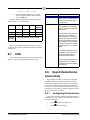
8.7 LEDS .........................................................................................................................................................................
8.8 OPEN ECHELON DEVICE CONNECTIVITY ...................................................................................................................
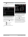
8.8.1 Configuring Echelon Devices.............................................................................................................................
8-1
8-1
8-1
8-2
8-2
8-3
8-3
8-3
8-3
8-4
8-4
8-4
8.8.1.1 Troubleshooting ....................................................................................................................................................... 8-5
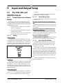
9 INPUT AND OUTPUT SETUP ................................................................................................................................ 9-1
9.1 THE 16AI, 8IO, AND MULTIFLEX INPUTS ................................................................................................................. 9-1
9.1.1 Connecting Sensors to Input Boards.................................................................................................................. 9-1
9.1.1.1 Wiring ...................................................................................................................................................................... 9-1
9.1.1.2 Sensor Wiring Types................................................................................................................................................ 9-1
9.1.1.3 Input Type Dip Switches ......................................................................................................................................... 9-1
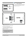
9.1.2 Power Connection .............................................................................................................................................. 9-2
9.1.3 Input Setup in E2 ................................................................................................................................................ 9-6
9.1.3.1
9.1.3.2
9.1.3.3
9.1.3.4
Configuring a Point from the Input Definitions/Status Screen................................................................................ 9-6
Using the Input Definitions/Status Screen............................................................................................................... 9-7
Setting Up Analog Inputs......................................................................................................................................... 9-7
Setting Up Digital Inputs ......................................................................................................................................... 9-9
9.2 THE 8RO, 8IO, AND MULTIFLEX OUTPUTS ............................................................................................................
9.2.1 Wiring Form C Contacts ..................................................................................................................................
9.2.2 MultiFlex Relay Outputs ..................................................................................................................................
9.2.3 Setting the Fail-Safe Dip Switch ......................................................................................................................
9.2.4 Relay Output Test Mode...................................................................................................................................
9.2.5 Wiring Outputs to Points.................................................................................................................................
9.2.6 The Output LED ...............................................................................................................................................
9.2.7 Output Setup in E2 ...........................................................................................................................................
9.2.7.1
9.2.7.2
9.2.7.3
9.2.7.4
9-10
9-10
9-10
9-11
9-11
9-12
9-12
9-12
Configuring a Point from the Output Definitions/Status Screen ........................................................................... 9-12
Using the Output Definitions/Status Screen .......................................................................................................... 9-13
Setting Up Digital Outputs..................................................................................................................................... 9-13
Setting Up Analog Outputs.................................................................................................................................... 9-14
9.3 CC-100 CASE CONTROLLERS ..................................................................................................................................
9.3.1 Inputs................................................................................................................................................................
9.3.2 Power Module Wiring ......................................................................................................................................
9.3.3 Valve Cable ......................................................................................................................................................
9.4 CCB CASE CONTROLLERS .......................................................................................................................................
9.5 ESR8 AND MULTIFLEX ESR VALVE OUTPUT WIRING ...........................................................................................
9-16
9-16
9-17
9-17
9-18
9-18
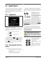
10 QUICK START ...................................................................................................................................................... 10-1
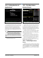
10.1 LOGGING ON ..........................................................................................................................................................
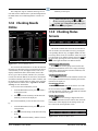
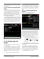
10.2 CLEANING OUT THE CONTROLLER ........................................................................................................................
10.3 SETTING NUMBER OF NETWORK DEVICES ............................................................................................................
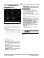
10.4 SETTING NUMBER OF APPLICATIONS ....................................................................................................................
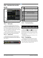
10.5 THE MAIN STATUS (HOME) SCREEN .....................................................................................................................
10.5.1 Customizing the Home Screen........................................................................................................................
10.6 COMMON SCREEN ELEMENTS ................................................................................................................................
10.6.1 The Header.....................................................................................................................................................
10-1
10-1
10-2
10-3
10-3
10-3
10-4
10-4
10.6.1.1 Header Icons ........................................................................................................................................................ 10-4
viii • Table of Contents
026-1610 Rev 10 06-APR-2010
10.6.2 The Function Keys ......................................................................................................................................... 10-4
10.6.3 The Help Line................................................................................................................................................. 10-4
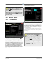
10.7 SCREEN TYPES ....................................................................................................................................................... 10-5
10.7.1 The Main Menu .............................................................................................................................................. 10-5
10.7.2 Status Screens ................................................................................................................................................ 10-5
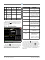
10.7.3 The Actions Menu........................................................................................................................................... 10-6
10.7.4 The Setup Screens .......................................................................................................................................... 10-7
10.7.5 System Configuration Menu........................................................................................................................... 10-7
10.7.6 The System Information Menu ....................................................................................................................... 10-8
10.8 TIME/DATE SETUP ................................................................................................................................................. 10-9
10.8.1 Setting the Time and Date.............................................................................................................................. 10-9
10.9 SET UP MODEM ................................................................................................................................................... 10-10
10.10 SET UP TCP/IP.................................................................................................................................................. 10-11
10.11 SET UP NETWORK BAUD RATES ...................................................................................................................... 10-12
10.11.1 RS232 Baud Rate ....................................................................................................................................... 10-12
10.11.2 I/O Network Baud Rate .............................................................................................................................. 10-12
10.12 SET UP USER ACCESS ....................................................................................................................................... 10-13
10.12.1 Changing Required User Access Levels .................................................................................................... 10-14
10.12.2 Creating a New User Account ................................................................................................................... 10-14
10.12.3 Deleting a User .......................................................................................................................................... 10-14
10.13 SET UP I/O NETWORK ....................................................................................................................................... 10-15
10.13.1 Specify Number of Boards.......................................................................................................................... 10-15
10.13.2 Checking Online Status.............................................................................................................................. 10-16
10.14 SET UP ECHELON NETWORK ............................................................................................................................. 10-16
10.14.1 Specifying Number of Devices ................................................................................................................... 10-16
10.14.2 Commissioning a Device............................................................................................................................ 10-17
10.14.2.1 The Service Button Method ............................................................................................................................. 10-17
10.14.2.2 The Manual ID Entry Method.......................................................................................................................... 10-19
10.15 LICENSE MANAGEMENT ....................................................................................................................................
10.15.1 Web Services ..............................................................................................................................................
10.16 SET UP ALARMING ............................................................................................................................................
10.16.1 Specifying Alarm Reporting Types.............................................................................................................
10.16.1.1
10.16.1.2
10.16.1.3
10.16.1.4
10-19
10-20
10-21
10-22
The Display Line.............................................................................................................................................. 10-22
The Alarm Output ............................................................................................................................................ 10-22
Dial-Out ........................................................................................................................................................... 10-22
The Echelon Network (The Alarm Annunciator) ............................................................................................ 10-22
10.16.2 Setting up an E2 to be an Alarm Annunciator ...........................................................................................
10.16.3 Alarm Dial-Out ..........................................................................................................................................
10.16.4 Introduction: Alarm Reporting ..................................................................................................................
10.17 SET UP GLOBAL DATA ......................................................................................................................................
10.17.1 Priority Settings .........................................................................................................................................
10.18 SET UP APPLICATIONS.......................................................................................................................................
10.18.1 Add/Delete an Application .........................................................................................................................
10.18.2 Using and Configuring a Setup Screen......................................................................................................
10-22
10-23
10-23
10-24
10-24
10-25
10-25
10-26
10.18.2.1 The Edit Menu ................................................................................................................................................. 10-26
10.18.2.2 Entering Setpoints............................................................................................................................................ 10-26
10.18.2.3 Navigating the Setup Screen............................................................................................................................ 10-27
10.18.3 Using the Help Key to get Property Help .................................................................................................. 10-28
11 SOFTWARE OVERVIEW ................................................................................................................................... 11-1
11.1 SUCTION GROUPS .................................................................................................................................................. 11-1
11.1.1 Introduction.................................................................................................................................................... 11-1
11.1.2 The (Standard) Suction Group Application ................................................................................................... 11-1
11.1.2.1 Overview of PID Control Strategy ...................................................................................................................... 11-1
11.1.2.2 Variable-Speed Compressors............................................................................................................................... 11-1
E2 RX/BX/CX I&O Manual
Table of Contents • ix
11.1.2.3 Floating Setpoint Control..................................................................................................................................... 11-1
11.1.3 The Enhanced Suction Group Application..................................................................................................... 11-1
11.1.3.1
11.1.3.2
11.1.3.3
11.1.3.4
11.1.3.5
Learning Mode..................................................................................................................................................... 11-2
Circuit Load Analysis .......................................................................................................................................... 11-2
The Control/Cycles Parameter............................................................................................................................. 11-2
Variable-Speed, Digital Scroll, and Digital Discus Compressor Support ........................................................... 11-2
Floating Suction Control...................................................................................................................................... 11-2
11.1.4 Hardware Overview ....................................................................................................................................... 11-2
11.2 CONDENSER CONTROL........................................................................................................................................... 11-3
11.2.1 Air Cooled Condensers .................................................................................................................................. 11-3
11.2.1.1 Air Cooled Strategy ............................................................................................................................................. 11-3
11.2.1.2 Temperature Differential Strategy ....................................................................................................................... 11-3
11.2.2 Evaporative Condensers ................................................................................................................................
11.2.3 Fan Control ....................................................................................................................................................
11.2.4 Condenser Split Mode ....................................................................................................................................
11.2.5 Fast Recovery.................................................................................................................................................
11.2.6 Hardware Overview .......................................................................................................................................
11.3 STANDARD CIRCUITS .............................................................................................................................................
11.3.1 Refrigeration Control.....................................................................................................................................
11.3.1.1
11.3.1.2
11.3.1.3
11.3.1.4
11-4
11-4
11-4
11-4
11-4
11-5
11-5
Temperature Monitor ........................................................................................................................................... 11-6
Temperature Control............................................................................................................................................ 11-6
Line Up(ESR)/Defrost ......................................................................................................................................... 11-6
Line Up(MFESR)/Defrost ................................................................................................................................... 11-6
11.3.2 Defrost Control .............................................................................................................................................. 11-6
11.3.2.1
11.3.2.2
11.3.2.3
11.3.2.4
11.3.2.5
Defrost States ....................................................................................................................................................... 11-6
Defrost Types....................................................................................................................................................... 11-6
Defrost Termination............................................................................................................................................. 11-7
Emergency Defrost .............................................................................................................................................. 11-7
Hot Gas Defrost with ESR8 and MultiFlex ESR................................................................................................. 11-7
11.3.3 Clean and Door Switches............................................................................................................................... 11-7
11.3.3.1 Clean Switches..................................................................................................................................................... 11-7
11.3.3.2 Door Switches...................................................................................................................................................... 11-7
11.3.4 Fan Control .................................................................................................................................................... 11-8
11.3.5 The TD3 Temperature
Display ........................................................................................................................................................................ 11-8
11.3.6 The Control Link CD Case Display ............................................................................................................... 11-8
11.3.7 Wiring............................................................................................................................................................. 11-8
11.4 CASE CONTROL CIRCUITS ................................................................................................................................... 11-10
11.4.1 Overview....................................................................................................................................................... 11-10
11.4.2 Case Circuit Control Software Overview..................................................................................................... 11-10
11.4.2.1 Valve Control..................................................................................................................................................... 11-11
11.4.3 Refrigeration Control................................................................................................................................... 11-11
11.4.3.1 EEVs (Liquid Pulse and Liquid Stepper)........................................................................................................... 11-11
11.4.3.2 EEPRs (Suction Stepper) ................................................................................................................................... 11-12
11.4.4
Defrost Control ........................................................................................................................................... 11-12
11.4.4.1
11.4.4.2
11.4.4.3
11.4.4.4
11.4.4.5
11.4.4.6
Defrost States ..................................................................................................................................................... 11-12
Defrost Types..................................................................................................................................................... 11-12
Defrost Termination........................................................................................................................................... 11-13
Demand Defrost ................................................................................................................................................. 11-13
Emergency Defrost ............................................................................................................................................ 11-13
The WAIT State................................................................................................................................................. 11-13
11.4.5 Anti-Sweat Control....................................................................................................................................... 11-13
11.4.5.1 Dewpoint Input Sources..................................................................................................................................... 11-14
11.4.6 Dual Temp Control....................................................................................................................................... 11-14
11.4.7 Fan Control .................................................................................................................................................. 11-14
11.4.8 Light Control ................................................................................................................................................ 11-14
x • Table of Contents
026-1610 Rev 10 06-APR-2010
11.4.9 Clean/Wash Mode ........................................................................................................................................ 11-14
11.4.10 Walk-In Freezer Control............................................................................................................................ 11-15
11.4.11 Fail-Safe Mode........................................................................................................................................... 11-15
11.4.11.1 Recoverable Sensor Failures............................................................................................................................ 11-15
11.4.12 Wiring.........................................................................................................................................................
11.4.13 Setting Up An Individual Case Controller.................................................................................................
11.4.14 Associating Case Controllers with Case Circuit Control Applications.....................................................
11.5 LOGGING GROUPS ...............................................................................................................................................
11.5.1 Data Compression........................................................................................................................................
11-16
11-16
11-16
11-16
11-17
11.5.1.1 Clipping.............................................................................................................................................................. 11-17
11.5.1.2 Incompressible Data Types................................................................................................................................ 11-17
11.5.2
11.5.3
11.5.4
11.5.5
Base Log Group ...........................................................................................................................................
Setting Up Logging ......................................................................................................................................
Logging Group Status Screen ......................................................................................................................
Log Reports ..................................................................................................................................................
11-17
11-17
11-18
11-18
11.5.5.1 Logging Group Report....................................................................................................................................... 11-19
11.5.5.2 Application Log Report ..................................................................................................................................... 11-19
11.5.5.3 System Log Report ............................................................................................................................................ 11-19
11.6 AIR HANDLING UNITS (AHU).............................................................................................................................
11.6.1 Overview ......................................................................................................................................................
11.6.2 Temperature Control....................................................................................................................................
11.6.3 Alternate Setpoints .......................................................................................................................................
11.6.4 Fan Control..................................................................................................................................................
11-20
11-20
11-20
11-20
11-20
11.6.4.1 Single-Speed Fans.............................................................................................................................................. 11-20
11.6.4.2 Two-Speed Fans................................................................................................................................................. 11-21
11.6.4.3 Variable-Speed Fans .......................................................................................................................................... 11-21
11.6.5 Economizer Control ..................................................................................................................................... 11-21
11.6.5.1 Economization Enable ....................................................................................................................................... 11-21
11.6.5.2 Economization Lockout Features ...................................................................................................................... 11-22
11.6.6 Digital Economizer Control.........................................................................................................................
11.6.7 Analog Economizer Control.........................................................................................................................
11.6.8 Dehumidification Control ............................................................................................................................
11.6.9 Curtailment ..................................................................................................................................................
11.6.10 Optimum Start/Stop (OSS) .........................................................................................................................
11.6.11 Separate Setpoints......................................................................................................................................
11.6.12 AHU Zone Control .....................................................................................................................................
11.6.13 Hardware Overview...................................................................................................................................
11.7 ZONE CONTROL ...................................................................................................................................................
11.7.1 Overview ......................................................................................................................................................
11.7.2 How Zones Work..........................................................................................................................................
11.7.3 Applications That May Be Connected To Zones..........................................................................................
11-22
11-22
11-22
11-22
11-22
11-23
11-23
11-23
11-24
11-24
11-25
11-25
11.7.3.1 MultiFlex RTU Board........................................................................................................................................ 11-25
11.7.3.2 MultiFlex RCB Board........................................................................................................................................ 11-25
11.7.3.3 AHUs ................................................................................................................................................................. 11-25
11.7.4 Temperature Control....................................................................................................................................
11.7.5 Zone Temperature ........................................................................................................................................
11.7.6 Economizer Control .....................................................................................................................................
11.7.7 Economization Enable ................................................................................................................................
11.7.8 The Effect of Enabling Economization.........................................................................................................
11.7.9 Dehumidification Control ............................................................................................................................
11.7.10 The Zone Humidity Input ...........................................................................................................................
11.7.11 The Effect of Enabling Dehumidification...................................................................................................
11-26
11-26
11-26
11-26
11-27
11-27
11-27
11-27
11.7.11.1 MultiFlex RTUs and RCBs.............................................................................................................................. 11-27
11.7.11.2 AHUs ............................................................................................................................................................... 11-27
11.7.12 Optimum Start/Stop (OSS) ......................................................................................................................... 11-27
E2 RX/BX/CX I&O Manual
Table of Contents • xi
11.7.13 Losing Contact With Zone Applications.....................................................................................................
11.7.14 Stand-Alone MultiFlex RTUs .....................................................................................................................
11.7.15 MultiFlex RTU/ARTC and AHU Zone Association....................................................................................
11.8 MULTIFLEX CUB BOARD ....................................................................................................................................
11.9 MULTIFLEX PAK BOARD ....................................................................................................................................
11.10 LIGHTING SCHEDULES .......................................................................................................................................
11.10.1 Overview.....................................................................................................................................................
11.10.2 Functions of the Lighting Schedule Application ........................................................................................
11.10.3 Control Method Select................................................................................................................................
11.10.4 Standard Control........................................................................................................................................
11-28
11-28
11-28
11-29
11-29
11-29
11-29
11-30
11-30
11-30
11.10.4.1 The Light Level Interface Cell (LLEV INTERFACE).................................................................................... 11-30
11.10.4.2 The Schedule Interface Cell (SCHEDIF) ........................................................................................................ 11-31
11.10.5 Alternate Control........................................................................................................................................ 11-31
11.10.5.1 Multi-Logic Combiner ..................................................................................................................................... 11-31
11.10.5.2 Offset Solar Control......................................................................................................................................... 11-32
11.10.6
The Basic Schedule Cell............................................................................................................................ 11-32
11.10.6.1 Slave Scheduling.............................................................................................................................................. 11-32
11.10.7 The Min ON/OFF Cell ...............................................................................................................................
11.10.8 The Proof Cell ............................................................................................................................................
11.10.9 Output Light Dimming ..............................................................................................................................
11.11 DEMAND CONTROL ............................................................................................................................................
11.11.1 Introduction to Demand Limit Control ......................................................................................................
11.11.2 Demand Monitoring ...................................................................................................................................
11.11.3 Load Shedding............................................................................................................................................
11-32
11-32
11-33
11-33
11-33
11-33
11-34
11.11.3.1 Definition ......................................................................................................................................................... 11-34
11.11.4 Shedding Levels.......................................................................................................................................... 11-34
11.11.5 Priority Levels ........................................................................................................................................... 11-34
11.11.6 How Demand Control Uses Load Shedding ............................................................................................. 11-36
11.11.6.1 Power Monitoring Input................................................................................................................................... 11-37
11.12 SENSOR CONTROL..............................................................................................................................................
11.12.1 Overview.....................................................................................................................................................
11.12.2 Analog Sensor Control ...............................................................................................................................
11.12.3 Cut In/Cut Out Setpoint Control ................................................................................................................
11.12.4 Digital Sensor Control ...............................................................................................................................
11.12.5 Logical Combination..................................................................................................................................
11.13 LOOP/SEQUENCE CONTROL ...............................................................................................................................
11.13.1 Layout of the Loop/Sequence Control Application ....................................................................................
11-37
11-37
11-37
11-37
11-37
11-38
11-38
11-38
11.13.1.1 Control Cells .................................................................................................................................................... 11-38
11.13.1.2 Output Cells ..................................................................................................................................................... 11-39
11.13.1.3 Diagram............................................................................................................................................................ 11-39
11.13.2 Loop/Sequence Control Cell Descriptions................................................................................................. 11-39
11.13.2.1
11.13.2.2
11.13.2.3
11.13.2.4
11.13.2.5
The Select Cell................................................................................................................................................. 11-39
The Setpoint Float Cell .................................................................................................................................... 11-40
The PID Control Cell ....................................................................................................................................... 11-40
The Filter Cell .................................................................................................................................................. 11-40
The Override Cell ............................................................................................................................................ 11-40
11.13.3 Output Cell Descriptions............................................................................................................................ 11-40
11.13.3.1 The Sequencer Cell .......................................................................................................................................... 11-40
11.13.3.2 The PWM Cell ................................................................................................................................................. 11-40
11.14 TIME SCHEDULING AND HOLIDAYS ................................................................................................................... 11-41
11.14.1 How Schedules Work.................................................................................................................................. 11-41
11.14.1.1
11.14.1.2
11.14.1.3
11.14.1.4
11.14.1.5
Events............................................................................................................................................................... 11-41
Absolute and Relative Events .......................................................................................................................... 11-41
Temporary Schedule Events ............................................................................................................................ 11-41
Overlapping...................................................................................................................................................... 11-42
Ranges.............................................................................................................................................................. 11-42
xii • Table of Contents
026-1610 Rev 10 06-APR-2010
11.14.2 Holiday Schedules......................................................................................................................................
11.15 POWER MONITORING .........................................................................................................................................
11.15.1 Overview ....................................................................................................................................................
11.15.2 Logging ......................................................................................................................................................
11-42
11-42
11-42
11-43
11.15.2.1 Power Monitoring Input................................................................................................................................... 11-43
11.16 ANTI-SWEAT SETUP ..........................................................................................................................................
11.16.1 How Anti-Sweat Works ..............................................................................................................................
11.17 HEAT/COOL CONTROL.......................................................................................................................................
11.17.1 Temperature Control..................................................................................................................................
11.17.2 Unoccupied Hysteresis..............................................................................................................................
11.17.3 Optimum Start/Stop (OSS) .........................................................................................................................
11.17.4 Setpoint Reset.............................................................................................................................................
11.17.5 Lead/Lag ....................................................................................................................................................
11.18 ANALOG AND DIGITAL COMBINERS ..................................................................................................................
11.19 TD CONTROL .....................................................................................................................................................
11.19.1 Overview ....................................................................................................................................................
11.19.2 Temperature Differential (TD) Strategy ....................................................................................................
11.19.3 TD Control Fail-Safes................................................................................................................................
11.19.4 Configuration .............................................................................................................................................
11.19.5 Setpoints .....................................................................................................................................................
11.19.6 Inputs..........................................................................................................................................................
11.19.7 Alarms ........................................................................................................................................................
11.20 PULSE ACCUMULATION .....................................................................................................................................
11.20.1 Overview ....................................................................................................................................................
11.20.2 Configuration .............................................................................................................................................
11.20.3 Outputs .......................................................................................................................................................
11.20.4 Accumulator Reset Types ...........................................................................................................................
11.20.5 Logging ......................................................................................................................................................
11.20.6 High Trip....................................................................................................................................................
11.21 IRRIGATION CONTROL .......................................................................................................................................
11.21.1 Overview ....................................................................................................................................................
11.21.2 Zones and Cycles .......................................................................................................................................
11-44
11-44
11-44
11-44
11-44
11-45
11-45
11-46
11-46
11-47
11-47
11-47
11-47
11-47
11-47
11-48
11-48
11-48
11-48
11-48
11-48
11-49
11-49
11-49
11-49
11-49
11-49
11.21.2.1 Cycle Control Types ........................................................................................................................................ 11-50
11.21.2.2 Timed ............................................................................................................................................................... 11-50
11.21.2.3 Volume............................................................................................................................................................. 11-50
11.21.3 Cycle Scheduling....................................................................................................................................... 11-50
11.21.4 Zone Inhibit ................................................................................................................................................ 11-50
11.21.4.1
11.21.4.2
11.21.4.3
11.21.4.4
11.21.4.5
Timed ............................................................................................................................................................... 11-50
Volume............................................................................................................................................................. 11-50
Rain Delay ....................................................................................................................................................... 11-50
Freeze Lockout................................................................................................................................................. 11-50
Alarm ............................................................................................................................................................... 11-50
11.21.5 Zone Bypass Inputs .................................................................................................................................... 11-50
11.21.5.1 Bypass Failsafe ................................................................................................................................................ 11-51
11.21.6 Flow Sensor-Related Tests......................................................................................................................... 11-51
11.21.6.1 Leak Test.......................................................................................................................................................... 11-51
11.21.6.2 Obstructed Zone Test....................................................................................................................................... 11-51
11.21.7 Service Modes ............................................................................................................................................
11.21.8 Heat Cut In/Cut Out Setpoints For Each Stage .........................................................................................
11.21.9 Cool Cut In/Cut Out Setpoints For Each Stage .........................................................................................
11.21.10 Dehumidification Control .......................................................................................................................
11.21.11 Two Speed Fan Control ..........................................................................................................................
11.21.12 Configuration ..........................................................................................................................................
11.22 FLEXIBLE COMBINER .........................................................................................................................................
E2 RX/BX/CX I&O Manual
11-51
11-51
11-51
11-51
11-51
11-52
11-52
Table of Contents • xiii
12 OPERATOR’S GUIDE TO USING THE E2 ...................................................................................................... 12-1
12.1 THE E2 HOME SCREEN .......................................................................................................................................... 12-1
12.1.1 RX Home Screen............................................................................................................................................. 12-1
12.1.2 BX Home Screen............................................................................................................................................. 12-1
12.1.3 CX Home Screen ............................................................................................................................................ 12-2
12.2 LOGGING ON AND ACCESS LEVELS ....................................................................................................................... 12-2
12.3 TOGGLING FULL OPTIONS ..................................................................................................................................... 12-3
12.4 NAVIGATION .......................................................................................................................................................... 12-3
12.4.1 Menus ............................................................................................................................................................. 12-3
12.4.2 Screen Types................................................................................................................................................... 12-5
12.4.3 The E2 Keypad ............................................................................................................................................... 12-6
12.5 CUSTOMIZING THE HOME SCREEN ........................................................................................................................ 12-8
12.6 MANUAL DEFROST AND CLEAN MODE ................................................................................................................. 12-8
12.7 OVERRIDES ............................................................................................................................................................ 12-9
12.8 CHECKING BOARDS ONLINE ................................................................................................................................ 12-10
12.9 CHECKING STATUS SCREENS ............................................................................................................................... 12-10
12.10 ALARMS ............................................................................................................................................................. 12-11
12.10.1 Accessing the Alarm Advisory Log............................................................................................................. 12-11
12.10.2 Viewing the Controller Advisory Log......................................................................................................... 12-11
12.10.3 Date and Time ............................................................................................................................................ 12-11
12.10.4 State............................................................................................................................................................ 12-11
12.10.5 Ack/Reset State ........................................................................................................................................... 12-12
12.10.6 Area Ctrl: Application: Property ............................................................................................................... 12-12
12.10.7 Advisory Message....................................................................................................................................... 12-12
12.10.8 Acknowledging, Resetting, and Clearing Log Entries ............................................................................... 12-12
12.10.8.1 Acknowledging ................................................................................................................................................ 12-12
12.10.8.2 Resetting .......................................................................................................................................................... 12-13
12.10.8.3 Clearing............................................................................................................................................................ 12-13
12.10.9 Facility Status Display (FSD) Alarms........................................................................................................ 12-14
12.11 VIEWING LOGS AND GRAPHS ............................................................................................................................ 12-14
12.11.1 Locating Logged Inputs/Outputs................................................................................................................ 12-14
12.11.1.1 Home/Status Screens ....................................................................................................................................... 12-14
12.11.1.2 Setup Screens ................................................................................................................................................... 12-15
12.11.1.3 Setting Up Input and Output Pointers.............................................................................................................. 12-15
12.11.2 Log View.....................................................................................................................................................
12.11.3 The Graph View .........................................................................................................................................
12.11.4 Zooming In and Out ...................................................................................................................................
12.12 LOW BATTERY NOTIFICATION ...........................................................................................................................
12-16
12-16
12-16
12-17
APPENDIX A: CASE TYPE DEFAULTS ............................................................................................................... A-1
APPENDIX B: PRESSURE/VOLTAGE AND TEMPERATURE/RESISTANCE CHARTS FOR ECLIPSE
TRANSDUCERS & RETAIL SOLUTIONS TEMP SENSORS ................................................................................ B-1
APPENDIX C: ALARM ADVISORY MESSAGES................................................................................................ C-1
APPENDIX D: PID CONTROL................................................................................................................................ D-1
APPENDIX E: COMPRESSED POINT LOG SAMPLE LIMITS AND PRECISION TABLE ......................... E-1
APPENDIX F: TROUBLESHOOTING .................................................................................................................... F-1
INDEX ............................................................................................................................................................................ I-1
1
Introduction
The E2 controller is a microprocessor-based control
system designed to provide complete control of compressor groups, condensers, refrigerated cases, and other components related to refrigeration and building control. The
E2 is the controlling component of a three-network configuration (RS485 I/O, Echelon® Lonworks™ Networks, and
Ethernet) that includes input and output communication
boards, remote communication software, and a variety of
sensors, probes, and transducers.
The E2 efficiently operates all systems that support
refrigeration (including compressor racks and condensers)
and other components not directly related to refrigeration
control, such as HVAC systems, anti-sweat heaters, and
sensor control modules.
Figure 1-1 - E2 Controller
1.1 The E2 Refrigeration
Controller
The E2 RX is available in three models: the RX-300,
RX-400, and RX-100. The E2 RX-300 is capable of controlling a single refrigeration system (including one condenser and up to four suction groups). The E2 RX-400 is
capable of controlling two separate refrigeration systems
(including two condensers and up to four suction groups).
The RX-100 is a low-cost alternative to the RX-300 with
fewer capabilities and a monochrome display.
The E2 RX is primarily designed to control temperature and defrost in refrigerated cases using either direct
control (connected to the E2 via I/O boards or ESR8
lineup control boards) or by using CC-100 case control
boards (connected via the LonWorks Network).
Table 1-1 shows the differences between capabilities
The E2 Refrigeration Controller
for the RX-300 and RX-400.
RX100
Capabilities
RX300
RX400
Analog Sensor Control
24
64
72
Anti-Sweat
8
16
64
Case Control
Circuits
0
48
64
Condensers
1
1
2
Digital Sensor Control
24
64
72
Holiday
Schedule
4
64
64
Power Monitoring
1
16
16
Standard Circuits
48
48
64
Suction
Groups
3
4
4
Pulse Accumulator
0
16
16
TD Control
4
16
24
Time Schedules
4
64
64
Table 1-1 - RX-100, RX-300, and RX-400 Comparison
1.2 The E2 Building Controller
The counterpart to the E2 RX is the E2 BX, which controls HVAC systems for low-rise retail, industrial, and
commercial buildings. The BX’s primary function is to
provide energy-efficient control of air handling units
(AHUs), rooftop units (RTUs), and other systems related
to environment control. In addition, the BX provides
Introduction • 1-1
extensive sensor control, logging, and graphing features
that allow the user to view accurate real-time information
about system conditions. The BX is equipped with many
power monitoring and demand control features that give
you the information you need to keep your site’s energy
consumption low.
The E2 BX is available in two models: the BX-300 and
BX-400. The only significant difference between the E2
BX-300 and the E2 BX-400 is the total number of building
control devices that may be operated by a single controller.
Table 1-2 shows the differences between capabilities for
the BX-300 and BX-400.
Capabilities
BX-300
Air Handlers
(AHU)
6
AHU Zone
32
Analog Sensor
Control
64
Demand Control
BX-400
The CX is equipped with many power monitoring and
demand control features that give you the information you
need to keep your site’s energy consumption low.
The E2 CX is available in three models: the CX-300,
CX-400, and CX-100. The only significant difference
between the E2 CX-300 and the E2 CX-400 is the amount
of C-Store equipment that may be operated by a single
controller. The CX-100 is a low-cost alternative to the CX300 with fewer capabilities and a monochrome display.
Table 1-3 shows the differences between capabilities for
the CX-300 and CX-400.
CX100
Capabilities
8
CX300
CX400
4
6
8
40
Air Handlers
(AHU)
72
AHU Zone
4
6
12
12
24
48
2
2
Analog Sensor Control
Digital Sensor Control
64
72
Anti-Sweat
4
8
16
1
1
1
Holiday Schedule
64
64
Demand
Control
Lighting Control
24
48
Digital Sensor Control
12
24
48
Power Monitoring
32
64
16
32
32
64
Holiday
Schedule
8
Pulse Accumulator
TD Control
16
28
Irrigation
2
2
2
Time Schedules
64
64
Lighting
Control
6
24
48
Power Monitoring
2
8
16
Pulse Accumulator
4
8
16
Standard Circuits
6
12
32
TD Control
8
16
28
Table 1-2 - BX-300 vs. BX-400 Comparison
1.3 The E2 Convenience
Store Controller
The CX controls HVAC, lighting, and refrigeration
systems for convenience store and small-box retail facilities. The CX’s primary function is to provide energy-efficient control of rooftop units as well as refrigeration and
defrost control of display cases and walk-in boxes. In
addition, the CX provides extensive sensor control, logging, and graphing features that allow the user to view
accurate real-time information about system conditions.
1-2 • E2 RX/BX/CX I&O Manual
Table 1-3 - CX-100, CX-300, and CX-400 Comparison
026-1610 Rev 10 06-APR-2010
CX100
Capabilities
Time Schedules
8
CX300
16
CX400
E2 RX
32
E2
Table 1-3 - CX-100, CX-300, and CX-400 Comparison
1.4
Networking Overview
1.4.1
E2 I/O Network
Most of the general purpose input and output communications devices required by the E2 to control refrigeration systems are connected to the E2 via the I/O Network.
The I/O Network is a simple RS485 three-wire connection
that allows data interchange between input boards (which
read sensor values and digital closures), output boards
(which carry out commands from E2’s control applications), and the E2 itself.
The I/O Network is the same thing as the COM A and
COM D Networks found on Retail Solutions’ previous
generation of controllers, REFLECS. This allows current
owners of Retail Solutions’ Refrigeration Monitor and
Control (RMC) or Refrigeration Monitor and Case Control
(RMCC) controllers to easily retrofit with an E2 RX without need for re-wiring.
MultiFlex
I/O
MultiFlex
I/O
CS-100
MultiFlex
I/O
CS-100
CC-100
MultiFlex
I/O
CC-100
CC-100
MultiFlex
I/O
MultiFlex
I/O
MultiFlex
I/O
MultiFlex
I/O
E2 RX & BX
RS485 I/O NETWORKS
Figure 1-2 - E2 RX/BX I/O Network Diagram
Figure 1-2 shows the peripherals that make up the I/O
Network:
• MultiFlex - The MultiFlex line of control system
boards provide a wide variety of input, output, and
smart control solutions, all of which are based on a
single universal hardware platform.
• 8ROSMT - Relay output board - activates and deactivates up to eight devices.
• Previous-generation I/O boards, such as 8RO,
8DO, and 4AO - are all still compatible with E2
I/O Network.
1.4.2
The E2 Echelon Lonworks
Network
The E2 is also compatible with a network platform
called Lonworks. This is most commonly referred to as
“the Echelon Network,” after the company who invented
the platform, the Echelon Corporation.
In general, peripherals with control functions — such
as case controllers, rooftop HVAC controllers, and other
E2 RX and BX units — are interconnected on the Echelon
Network. These controllers do most of their own computa-
Networking Overview
Introduction • 1-3
tion and system control, but they communicate with other
E2s to provide logging, alarm control, and other functions.
In addition to these, Retail Solutions also offers Echeloncompatible input and output boards similar to those available for the RS485 Network.
E2 RX
E2
the E2 that enables communication.
1.4.3
E2s
Interconnection With Other
In large installations where more than one refrigeration
system is present, or where E2s are controlling both refrigeration and building HVAC systems in the same site, the
E2s share information with each other across either the
Echelon Network or via Ethernet.
Echelon Box-To-Box
MultiFlex
I/O
MultiFlex
I/O
CS-100
CS-100
CC-100
CC-100
MultiFlex
I/O
MultiFlex
I/O
ECHELON CABLE (daisy chain)
CC-100
MultiFlex
I/O
MultiFlex
I/O
MultiFlex
I/O
MultiFlex
I/O
Ethernet Box-To-Box
E2 RX & BX
ECHELON NETWORKS
CAT5 CABLE
Figure 1-3 - E2 RX Echelon Network Diagram
Figure 1-3 shows the E2 RX peripherals that communicate across the Echelon Network:
Switch
Figure 1-4 - E2 RX/BX Network
• CC-100 - Case control board - controls all lights,
fans, defrost, and refrigeration for a single case. The
CC-100 controls pulse or stepper valves to provide
precise evaporator control, resulting in better temperature maintenance and energy efficiency.
• ESR8 - Evaporator stepper regulator - the analog
outputs on this board allow the E2 to control circuit
temperature in up to eight circuits using suctionside mounted electronic evaporator pressure regulators (EEPRs).
• TD3 - Temperature display - has three inputs that
monitor case temperature, product temperature and
defrost status.
• Third Party Echelon Devices - Echelon® LONMARK® devices communicate with E2 through its
"Open Echelon" networking feature, and require a
license key and a description file that is loaded into
1-4 • E2 RX/BX/CX I&O Manual
026-1610 Rev 10 06-APR-2010
1.5 Documentation Overview
The E2 RX and BX controllers are among the most
versatile and customizable control system products available on the market. Because of the enhanced capabilities
of the E2s, programming, installation, and operation of E2
and its accompanying peripherals are supported by several
different Retail Solutions publications. All of the publications listed below can be ordered by contacting Retail
Solutions:
• E2 Installation and Operation Manual for RX
Refrigeration, BX HVAC, and CX Convenience
Store Controllers (026-1610) - The manual you are
currently reading. The Installation and Operation
Manual covers hardware installation, network
setup, and important operator functions such as
viewing status screens or logs, and performing
manual defrosts.
The Quick Start section (Chapter 8) is designed to
guide you quickly through setup of the most simple
and vital refrigeration control applications (such as
suction groups and condensers). More detailed
information is included in the online help.
• Router and Repeater Installation Guide (P/N 0261605) - If you have a large site with 64 or more
devices on the Echelon Network, you might require
the use of a router or repeater to properly set up
your Echelon Network. The Router and Repeater
Installation Guide will help you determine when a
router or repeater should be used, how and where to
set it up, and how to configure the E2(s) on the network to interact with the router or repeater.
• Peripherals Manual (P/N 026-1701) - The Peripherals Manual gives important installation information about sensors, transducers, thermostats, and
other essential items that are a part of every Retail
Solutions control network. The Peripherals Manual
is not necessary for field installation instructions
(these are given in the User’s Guide); however, it
may be a useful reference for contractors and
OEMs who require more information about a specific peripheral.
• MultiFlex ESR Installation and Operation Manual (P/N 026-1720) - From general information to
details on mounting, wiring, and heat dissipation,
the MultiFlex ESR manual provides the information you need to install and operate the MultiFlex
ESR board, in addition to valuable information on
software setup and valve control.
Documentation Overview
• MultiFlex I/O Board Installation and Operation
Manual (P/N 026-1704) - Installation and operation manual for the MultiFlex 16 and all versions of
the MultiFlex combination input/output board,
excluding unit controllers such as the CUB and
RTU.
• MultiFlex CUB/CUB II Condensing Unit Board
Installation and Operation Manual (P/N 0261705) - Installation and operation manual for the
MultiFlex CUB (old style) and the MultiFlex CUBII family, which includes the CUB-II and CUB-TD.
• MultiFlex RTU Rooftop Controller Installation
and Operation Manual (P/N 026-1706) - Installation and operation guide for the MultiFlex RTU
(replacement for ARTC).
• MultiFlex RCB Rooftop Controller Installation
and Operation Manual (P/N 026-1707) - An
improved version of the MultiFlex RTU, the RCB
has 16 fully configurable analog and digital input
points. The RCB also has four analog outputs for
use in controlling variable speed fans, economizers,
or modulating heating and/or cooling valves. The
RCB also features a more sophisticated HHT interface and updated algorithms for controlling heating,
cooling, dehumidification, and air quality. Refer to
this manual for more information on the MultiFlex
RCB Rooftop Controller.
• E2 User’s Manual Supplement for Flexible Combiner Programming (P/N 026-1620) - The Flexible
Combiner application is an advanced I/O control
program used to combine multiple analog and digital input values using programmed equations similar to those used in spreadsheets, and is a new
feature of E2 versions 2.20 and above. Refer to this
manual for more information on the Flexible Combiner application.
• Facility Status Display (FSD) Installation and
Operation Manual (P/N 026-1400) - The FSD
reports alarm information and more, (such as temperatures, occupancy, case status, and setpoints)
and provides a centralized device for store personnel to review information by communicating with
the E2 via Ethernet connectivity (minimum E2
firmware rev. 2.68F01). Refer to this manual for
more information on the Status Display application.
• Square D Smart Breaker Control Manual (P/N
026-1711) - The Smart Breaker products are
designed to allow the Retail Solutions family of site
controllers to command control panels (minimum
E2 firmware rev. 2.71F01). A breaker panel generally consists of a series of circuit breakers that are
Introduction • 1-5
flipped from OFF to ON and from ON to OFF by
commands sent from E2 through MODBUS or a
Square D Smart Breaker Gateway board. Refer to
this manual for more information on the Square D
Breaker Panel application.
1.6 On-Line Help System
Overview
The E2 On-Line Help is the primary source frontpanel/interface users will have to consult when seeking
instruction on properties, screens, menus, and troubleshooting of hardware/software problems. The on-line help
topics are designed to minimize the time the user would
otherwise have to spend searching through the manual to
find information. Press + keys to open the
General Help menu.
To use on-line help from any screen in the E2 front
panel interface, simply press the E2’s permanent Help
key. This opens a pop-up window containing either
information about the screen or menu you are currently on,
or information about the input, output, or setpoint you
have highlighted with the cursor (if available). After the
Help key has been pressed, will open the General Help menu containing Troubleshooting options.
1.7
Software Licensing
Some applications in the E2 are available only when
activated with a unique license key that is obtained
through Retail Solutions. Software licensing (see Section
10.15, License Management) allows the user to activate
certain features in the E2, such as Web Services and thirdparty controllers. Call your Retail Solutions sales representative at 770-425-2724 for more information about
software licensing.
1-6 • E2 RX/BX/CX I&O Manual
026-1610 Rev 10 06-APR-2010
2
Hardware Overview
This section gives an overview of the E2, the hardware, and how it communicates across the I/O and Echelon Networks to control an entire system.
2.1
E2 Hardware
The E2 controller is programmed to monitor and command all aspects of a refrigeration or building environmental control system. The E2 uses both an RS485 I/O
Network and a LonWorks Network to gather data from
input devices, communicate with other E2s, and activate
or deactivate loads.
In general, an E2 control network will consist of the
following components:
1.
E2 - The “brain” of the control network, which
performs all necessary computations and sends
commands to the output devices that control the
system.
2.
Input Boards - Transfer readings to the E2.
3.
Output Boards - Banks of relays, digital pulse
outputs, or analog outputs, which the E2 may use
to control loads.
4.
Smart Boards - Boards such as case controllers
(for refrigeration) or rooftop controllers (for
building control) that perform control functions
for an individual case or rooftop unit, and send
the data to the E2 for logging and alarm purposes.
5.
Modem - For remote communication via phone,
if necessary.
6.
Network Wiring - Wiring that connects the E2 to
other E2s, and all the input, output, and smart
boards.
7.
Sensors and Loads - The “eyes” and “hands” of
the control network. Sensors “see” what needs to
be controlled on the network, and Loads are what
can be controlled, or more specifically, be turned
on and off, such as compressors, condensers,
lights, and fans.
Figure 2-1 - E2 Front Panel
Dimensions
Standard Mount:
9.06” W x 12.06” H x 3.75” D
Recessed Mount:
9.06” W x 10.56” H x 2.0” D
Base:
10.56” W x 10.56” H x 3.75” D
Operating
Temp
-40°F to 149°F (-40°C to 65°C)
Storage Temp
-40°F to 158°F (-40°C to 70°C)
Operating
Humidity
5% - 95% RH non-condensing at 90°F
Storage
Humidity
5% - 100% RH
Power
VA Load
24 VAC ±20%, 50/60 Hz, Class 2
50
Table 2-1 - E2 Specifications
NOTE: Contact Retail Solutions Customer
Service at 770-425-2724 for E2 controller
part numbers and model descriptions.
E2 Hardware
Hardware Overview • 2-1
2.1.1
(CPU)
E2 Main Processor Board
2.1.3
E2 Keypad
Figure 2-4 - E2 Keyboard
Figure 2-2 - E2 CPU (RX-100 Version Shown)
The E2 CPU or main processor board (Figure 2-2)
contains the CPU, Ethernet port, and memory used for logging. The 3.6V battery for the E2 is located on this board
and protects log and alarm data during power loss. The
main processor board connects to the PIB via a ribbon
cable. The RX- and CX-100 versions support monochrome display only. For optimum viewing, backlight and
contrast adjusts are available for customizing the monochrome display depending on the user’s needs.
2.1.2
(PIB)
E2 Processor Interface Board
The E2 has a QWERTY style keyboard layout with
two rows of function keys. The first row (-) is
comprised of screen-specific function keys, and the second row has designated icon keys. The five icon keys are
Help , Alarms , Home , Menu , and
Back .
2.1.4
LEDs
The PIB, main processor board, and keyboard (located
behind the main board) LEDs can be used to determine the
status of normal operating parameters for the unit.
PIB LEDs
Status
Green (14)
ON: Power is being applied to the
PIB
Yellow (RX1)
ON: Communication is being received on RS485 Port 1A
Yellow (RX2)
ON: Communication is being received on RS485 Port 1B
Red (TX)
ON: Communication is being sent
on RS485 Port 1A and 1B
Table 2-2 - PIB LED’s Status
Figure 2-3 - E2 PIB
The E2 Processor Interface Board (PIB) interfaces the
power and most all communications with the main processor board, and contains all field wiring connections. The
PIB allows you to connect an external keyboard, accessory
cards, and an external computer. All RS485 and Echelon
Network connectors are located on the PIB.
2-2 • E2 RX/BX/CX I&O Manual
026-1610 Rev 10 06-APR-2010
Main Board
(CPU) LEDs
Status
Green (D1
General Status LED for
E2 and Blank
Face E2)
1 blink every two seconds (1 second ON, 1 second OFF): Main
board is operating normally.
Solid ON: E2 is booting up.
Faster blinks per second: Indicates an error condition with the
hardware or firmware.
Green (D18
Boot Status
LED)
ON: E2 is booting up.
Table 2-3 - Main Board (CPU) LED’s Status
Keyboard
LED
Status
Green (D5
General Status LED)
1 blink every two seconds (1 second ON, 1 second OFF): Status is
normal.
4 blinks per second: A flash and/
or crystal problem has been detected. Board should be replaced.
Table 2-4 - Keyboard LED’s Status
Figure 2-5 - Mounting the Internal Modem Board
2.2 I/O Network Boards
and Peripherals
2.2.1
The Gateway Board
2.1.5
PC-104 Peripherals: The
Internal Modem (Previous Generation Processor Board)
CAUTION: Power down the E2 before plugging the modem into the PC-104 slot. Failure
to do so can damage the modem and void the
warranty.
The E2’s internal modem mounts in the PC-104 slot
located at the top left of the E2 main board (See Figure 25). Disconnect power to the unit, and carefully plug the
male pins on the back of the modem card into the E2’s PC104 slot. Use the standoffs and screws supplied with the
modem card to secure the card to the main board, as
shown in Figure 2-5. When finished, restore power to the
E2.
Figure 2-6 - Gateway Board
I/O Network Boards and Peripherals
Hardware Overview • 2-3
The Gateway board is an RS485 to RS485 converter.
One side of the Gateway is always connected to the Retail
Solutions I/O Network. The other side of the Gateway is
the receiver bus (RS485). The receiver bus is connected to
one or more RS485 devices depending on which type of
Gateway is being used. The Gateway interfaces devices to
the Einstein/E2 and legacy Retail Solutions controller
(REFLECS) by simulating 16AI and 8RO boards using
Retail Solutions standard I/O board protocol. The Gateway can also convert third-party controller protocols to
Retail Solutions protocol for custom cells created in the
Einstein/E2 to interface with third-party controllers (Danfoss, Woodley, etc.).
2.2.2.1
MultiFlex 16 Input Board
The Gateway performs one of two basic functions:
1.
It allows control of and/or status of a device using
I/O board simulation
2.
Converts a third-party protocol to Retail Solutions I/O Net protocol and interfaces to a custom
cell in Einstein/E2
P/N
Gateway Model
810-3500
RF Gateway
810-3700
IRLDS II Gateway
810-3760
RLDS Gateway
810-3710
Danfoss MicroCool Gateway
810-3711
Woodley Case Controller
Gateway
810-3712
Woodley Pack Controller
Gateway
810-3720
Cutler Hammer Breaker
Gateway
810-3721
Square D Breaker Gateway
Table 2-5 - Gateway Board Models
2.2.2
MultiFlex Boards
The MultiFlex line of control system boards provides a
wide variety of input, output, and smart control solutions,
all of which are based on a single universal hardware platform. The board design uses flash-uploadable firmware
and plug-in expansion boards to configure the base platform board and apply it for use as an input board, relay
output board, analog output board, or a combination I/O
board.
2-4 • E2 RX/BX/CX I&O Manual
Figure 2-7 - MultiFlex 16 Input Board
The MultiFlex 16 input board offers sixteen combination analog/digital input points for use by Retail Solutions
E2, Einstein, and REFLECS control systems. The MultiFlex 16 may be used in retrofits with no additional hardware or software setup or upgrades.
The MultiFlex 16 is designed to be 100% compatible
with the previous generation of Retail Solutions input
boards (the 16AI), communicates with the site controller
via an RS485 connection to a REFLECS COM A&D Network or an E2 I/O Network. Dip switches on the board set
the network ID (board number) and baud rate.
The board also provides both +5VDC and +12VDC
output voltage points for use in powering transducers or
other input devices that require power.
The MultiFlex 16 has a Hand-held Terminal interface
Section 2.2.4, Hand-held Terminal (P/N 814-3110) that
may be used by technicians to view the input voltage and
engineering unit values for each input point without need
of a voltmeter or front panel controller display.
Table 2-6 shows the part number of the MultiFlex 16.
P/N
810-3013
Model Name
MultiFlex 16
Description
16 analog/digital inputs, no outputs
Table 2-6 - MultiFlex 16 Input Board Model
026-1610 Rev 10 06-APR-2010
The MultiFlex 16 is designed with several features that
make it easy to install, wire, and configure. These main
user interface features are shown in Figure 2-7.
The MultiFlex combination I/O boards consist of up
to 16 combination digital/analog inputs, and a combination of relay outputs, digital outputs, and analog outputs.
2.2.2.2
MultiFlex Combination Input/
Output Boards
All boards feature both +5VDC and +12VDC output
voltage points for use in powering transducers or other
input devices that require power.
On the RS485 Network, the MultiFlex combination
input/output boards present themselves to Einstein, E2, or
REFLECS site controllers as 16AI Analog Input Boards,
8RO Relay Output Boards, 8DO Digital Output Boards,
and/or 4AO Analog Output Boards, depending on what
type of inputs or outputs are equipped. Dip switches are
used to assign network ID numbers to each board type.
Figure 2-8 - MultiFlex Combination Input/Output Board (Side
View)
The MultiFlex combination input/output boards also
support a Hand-held Terminal interface, Section 2.2.4,
Hand-held Terminal (P/N 814-3110) which allows technicians to view input values, check relay and analog output
states, and override output points with fixed digital or analog values. For more information on MultiFlex I/O boards,
refer to the MultiFlex I/O Board Installation and Operation Manual (P/N 026-1704).
Table 2-7 shows the available models of MultiFlex
combination input/output boards with description and part
numbers.
P/N
Model
Name
Description
810-3063
MultiFlex
88AO
8 analog/digital inputs, 8
relay outputs, 4 analog outputs
810-3064
MultiFlex
88
8 analog/digital inputs, 8
relay outputs
810-3065
MultiFlex
168AO
16 analog/digital inputs, 8
relay outputs, 4 analog outputs
Table 2-7 - MultiFlex Combination Input/Output Board Models
Figure 2-9 - MultiFlex Combination Input/Output Board (Top
View)
There are several models of the MultiFlex board that
combine the functionalities of input boards, relay output
boards, digital output boards, and analog output boards.
The MultiFlex combination input/output boards are
designed to be replacements for the 8IO Combination
Input/Output Board, but the MultiFlex board provides several new hardware options and software features.
I/O Network Boards and Peripherals
Hardware Overview • 2-5
810-3066
MultiFlex
168
16 analog/digital inputs, 8
relay outputs.
810-3067
MultiFlex
168DO
16 analog/digital inputs, 8
relay outputs, 4 digital outputs
810-3072
MultiFlex
1616L
16 analog/digital inputs,
16 low-voltage (24VAC
rated) relay outputs
810-3073
MultiFlex
1616LAO
16 analog/digital inputs,
16 low-voltage (24VAC
rated) relay outputs, and 4
analog outputs.
810-3077
MultiFlex
1616LDO
16 analog/digital inputs,
16 low-voltage (24VAC
rated) relay outputs, and 4
pulse-width modulating
digital outputs
Table 2-7 - MultiFlex Combination Input/Output Board Models
2-6 • E2 RX/BX/CX I&O Manual
026-1610 Rev 10 06-APR-2010
2.2.2.3
MultiFlex CUB
The MultiFlex Condensing Unit Board (CUB) is a
“smart” input/output board designed to control single condensing units. A single condensing unit is a self-contained
compressor and condenser bearing unit which controls
refrigeration in a single case line-up or walk-in cooler.
The MultiFlex CUB uses the same general hardware
configuration as a MultiFlex 168AO. It is equipped with a
processor and extra memory to allow it to control compressors, condensers, refrigeration, and defrost for a single
condensing unit using on-board I/O and control algorithms.
The RCB is an improved version of the MultiFlex
RTU. The RCB has sixteen fully configurable analog and
digital input points, whereas the RTU has only eight
inputs, two of which are configurable. The RCB has four
analog outputs for use in controlling variable speed fans,
economizers or modulating heating and/or cooling valves,
whereas the RTU has only two analog outputs for use only
with VS fans and economizers. The RCB also features a
more sophisticated HHT interface and updated algorithms
for controlling heating, cooling, dehumidification, and air
quality.
The MultiFlex RCB has its own installation and operation manual, (P/N 026-1707).
The MultiFlex CUB has its own installation and operation manual, (P/N 026-1706).
2.2.2.4
MultiFlex RTU (BX and CX Only)
Similar in design to the MultiFlex combination input/
output boards, the MultiFlex RTU board is designed specifically for operating package rooftop HVAC units as part
of an E2 BX or REFLECS BCU building control system.
The MultiFlex RTU is designed to be a replacement for the
previous generation ARTC, and is 100% compatible with
all legacy E2 BX and BCU systems.
The MultiFlex RTU board has 16 analog inputs, 8
relay outputs and 4 analog outputs. Most of these I/O
points are reserved for sensors and input devices required
to read environmental data (such as space and supply air
temperature) and control all output devices that control the
environment (such as heat/cool stages and dampers). The
RTU relay outputs are rated for line voltage (240VAC).
LEGEND
1
INPUT POWER
(24VAC)
9
RS485 TERMINATION
JUMPERS
2
RS485 I/O NETWORK
10
HAND-HELD TERMINAL JACK
3
RCB INPUTS 1-8
11
RELAY OUTPUT CONNECTORS
4
RCB INPUTS 9-16
12
RELAY OUTPUT FUSES
(2A rated, 250V slowblow)
5
NETWORK ID DIP
SWITCHES (S3, S4)
13
RELAY STATUS LEDs
6
INPUT TYPE DIP
SWITCHES (S1, S2)
14
OUTPUT FAIL-SAFE
SWITCHES
The MultiFlex RTU has its own installation and operation manual, (P/N 026-1705).
7
15
ANALOG OUTPUTS
2.2.2.5
MultiFlex Rooftop Control Board
(RCB) (BX and CX Only)
BOARD STATUS LEDs
(Code A, Code B, General
Status)
8
DC POWER OUTPUTS
(3 at +5VDC, 1 at
+12VDC)
16
NETWORK STATUS
LEDs
The RTU board controls the rooftop unit directly with
its built-in heating, cooling, and humidity control algorithms. It may operate in stand-alone mode, or it may
interface with an E2 BX or BCU to control the store environment in zones and pass along logging and alarm information.
The MultiFlex Rooftop Control Board (RCB)
(P/N 810-3062) is a rooftop HVAC control board for use
either as a stand-alone controller or in zone control applications using a Retail Solutions E2 BX building control
system. The MultiFlex RCB is capable of controlling heat
and cool stages, fans, humidification and dehumidification
devices, economizers using on-board I/O and control algorithms, as well as monitor and interact with other building
control systems and peripherals (such as smoke alarms and
CO2 sensors).
I/O Network Boards and Peripherals
Table 2-8 - MultiFlex RCB
2.2.2.6
MultiFlex PAK Board
The PAK is a distributed pack (rack) controller that
controls compressors and condenser fans. The PAK can
control up to 8 compressor groups containing up to 16
compressors. The compressor control strategy is Fixed
Steps with setpoint/deadband using ON and OFF delays.
Up to 20 Fixed Steps can be configured.
Hardware Overview • 2-7
The PAK can control up to 4 condenser fan groups
containing up to 8 total condenser fans. The PAK condenser control strategy is sequential TD control with setpoint/deadband using ON and OFF delays.
The PAK has a compressor/condenser interlock feature that will override TD control and force the condenser
fans to stage off using the TD control OFF delay when all
compressors are off. This feature can be disabled with an
Enable/Disable setpoint or when the discharge pressure is
above a configurable setpoint.
The MultiFlex PAK boards consist of two circuit
boards: a bottom layer with 16 combination digital/analog
inputs, and a plug-in top layer which contains a combination of 8 relay outputs and 4 digital DC voltage outputs.
The analog outputs on the Multiflex PAK drive solid
state relays to control the fan stages. The relays control the
compressor groups.
The communication interface is RS485 I/O using the
Standard Extended Address Form for Retail Solutions Distributed Controllers. Currently, the PAK is designed to
interface with the Retail Solutions E2 controller.
2.2.3
The MultiFlex ESR Board
The MultiFlex ESR Valve Regulator board (P/N 8103199), shown in Figure 2-1, is an RS485 I/O Network
electronic stepper valve regulator capable of driving up to
eight stepper motor valves, which are typically used to
control temperature.
10
3
9
7
8
1
2
3
4
5
Valve Connectors (8)
24VAC CT 75 VAC Power Input
General Status LED
I/O Network Input
TX and RX LEDs
6
7
8
9
10
Termination Jumpers
HHT Jack
Network Address Switches
Open LED (8)
Close LED (8)
Figure 2-1 - MultiFlex ESR Board Layout
The MultiFlex ESR uses suction side variable-position
evaporator regulators (ESRs) to vary evaporator pressure
for an entire circuit and is an alternative to mechanical
EPR control.
The MultiFlex ESR receives input data from a Retail
Solutions E2 controller (via the I/O Network) and then
regulates the stepper valves according to the data from the
E2.
LEGEND
1
INPUT POWER
(24VAC)
9
RS485 TERMINATION
JUMPERS
2
RS485 I/O NETWORK
10
HAND-HELD
TERMINAL JACK
3
PAK INPUTS 1-8
11
RELAY OUTPUT
CONNECTORS
4
PAK INPUTS 9-16
12
RELAY OUTPUT FUSES
(2A rated, 250V slowblow)
5
NETWORK ID DIP
SWITCH (S3)
13
RELAY STATUS LEDs
6
INPUT TYPE DIP
SWITCHES (S1, S2)
14
RELAY FAIL-SAFE
SWITCHES
7
BOARD STATUS LEDs
(Code A, Code B, General
Status)
15
PAK ANALOG
OUTPUTS 1-4
8
DC POWER OUTPUTS
(3 at +5VDC, 1 at
+12VDC)
16
NETWORK STATUS
LEDs
Table 2-9 - MultiFlex PAK
2-8 • E2 RX/BX/CX I&O Manual
Each MultiFlex ESR board requires a Class 2, 80VA
24VAC center-tapped transformer for power. Retail Solutions transformer (P/N 640-0080) is a multi-tapped primary transformer that may be used with the MultiFlex
ESR board.
2.2.4
Hand-held Terminal (P/N
814-3110)
The Hand-held Terminal (HHT) is used by manufacturers and service technicians to diagnose and test several
of Retail Solutions' existing and legacy products. The
HHT can be used on any Retail Solutions product with an
RJ-11 connector. The most common applications include:
• All MultiFlex I/O boards and the 8ROSMT
• All Gateway boards
• Stand-alone MultiFlex boards (RTU, RCB, PAK,
CUB)
026-1610 Rev 10 06-APR-2010
• CCB and CC-100 case controllers
The HHT does not require a separate power source.
The unit is powered from the RJ-11 connector on the
peripheral equipment. The HHT includes a standard male
RJ-11 to male RJ-11 cable.
NOTE: The 9V battery and 9-12V DC adapter
connection are not used on this HHT model
(P/N 814-3110).
1
with any refrigeration system or environmental control
component.
The 8RO board is the direct link between the E2 and
component operation. Information gathered by the controller from the input boards is checked against current
stored setpoints. If differences in the received input data
and the setpoint information are detected, a signal is either
sent to the proper 8RO relay, or an existing signal is discontinued. Through the use of this relay signal, control
functions that can be properly maintained by a simple contact closure sequence are effectively operated by the E2.
The 8RO board is easily installed and operated within
the Retail Solutions Network environment because of its
straightforward design. Several of these features are
shown in Figure 2-11.
2
14
3
13
4
5
6
12
11
10
7
8
9
1 The power switch determines if the HHT is
LEGEND
8 Scrolls list selections and scrolls through
ASCII characters if in a text field
in self-powered mode (BATT), ext power (EXT),
or if powered from a target device (HOST)
2 External Power Connector (9-12 VDC)
3 F2- Main Menu
9 RS-485 Connector
10 Cancel - clears/erases text in editable field;
4 Up Arrow - moves to previous screen,
editable field, or top of screen
5 Right Arrow - selects last editable field
starting from bottom of screen; selects
last editable field from bottom to top
6 Enter - save into memory
7 Numeric keypad
11 Down Arrow - moves to next screen,
editable field, end of screen, or advances
12 Left Arrow - selects first editable field from
top of screen, and next editable field from
top to bottom
13 F1 - Home Screen
Figure 2-11 - 8RO Relay Output Board
cancels overrides
14 LCD - four lines of 16 characters
Figure 2-10 - Hand-held Terminal (814-3110)
2.2.5
The 8RO and 8ROSMT Relay
Boards
The 8RO (P/N 810-3005) board is a general-purpose
board used to connect an E2 to any of eight standard control relay outputs, but is now obsolete and has been
replaced by the 8ROSMT (P/N 810-3006) board.
Figure 2-12 - 8ROSMT Relay Output Board
To function, the 8RO board must be connected through
either the Echelon Network or the RS485 I/O Network to
the E2. When properly installed, the 8RO receives an electrical impulse from the E2, which either opens or closes
any of eight contact relays. Output definitions within the
E2 allow the user to configure the 8RO board to interact
I/O Network Boards and Peripherals
Hardware Overview • 2-9
2.2.6
4AO Analog Output Board
The 4AO Analog Output Board (P/N 815-3030) (Figure 2-13) is configured with four analog output connections that provide a variable voltage signal to any of four
analog devices that may be controlled by a single E2. Two
4-20mA outputs are provided for channels 1 and 2. The
4-20mA outputs provide a variable current for applications
that are either externally powered or that require power
from the 4AO board.
9
2.2.7
8DO Digital Output Board
and PMAC II Anti-Sweat Controller
For control of anti-sweat heaters, Retail Solutions supplies the 8DO Digital Output board (P/N 810-3050). The
8DO has eight outputs which may pulse up to 150mA at
12VDC.
Since the 8DO is primarily designed to control antisweat heaters, the 8DO is the heart of Retail Solutions’
Pulse Modulated Anti-Sweat Control (PMAC II) panel.
The PMAC II (P/N 851-1000) provides 16 channels of
anti-sweat control circuitry. The PMAC II panel combines
the 8DO with high-capacity relays in a single enclosure,
providing 256 total amps of anti-sweat heater operation.
The 8DO is shown in Figure 2-15. The PMAC II is
shown in Figure 2-16.
4
5
7
8
Transmitting (TX ) and Receiving (RX) LEDs
Alarm and Status Indicator LEDs
8 Analog Outputs (4)
9 4-20mA Channels (2)
Hand-held Terminal (HHT) Jack
Figure 2-13 - 4AO Analog Output Board (P/N 815-3030)
The previous generation 4AO Analog Output Board,
(P/N 810-3030) (Figure 2-14) is configured with four analog output connections that provide a variable voltage signal to any of four analog devices that may be controlled by
a single E2.
I
D
O
SC
Figure 2-15 - 8DO Digital Output Board
D
E
U
N
I
T
N
Figure 2-16 - PMAC II Anti-Sweat Control Panel
Figure 2-14 - 4AO Analog Output Board - DISCONTINUED
2-10 • E2 RX/BX/CX I&O Manual
026-1610 Rev 10 06-APR-2010
2.3 Echelon Network
Boards and Peripherals
2.3.1
The 16AIe (Discontinued)
board similar in function to its I/O Network counterpart,
the 8RO. The 8ROe board is the direct link between the E2
and component operation. Information gathered by the
controller from the input boards is checked against current
stored setpoints. If differences in the received input data
and the setpoint information are detected, a signal is either
sent to the proper 8ROe relay, or an existing signal is discontinued. Through the use of this relay signal, control
functions that can be properly maintained by a simple contact closure sequence are effectively operated by the E2.
The 8ROe features Form C contacts for wiring outputs
as either normally open or normally closed. Fail-safe dip
switches on the 8ROe allow the installation technician to
specify the desired state of each relay in case of communications loss.
This board has been discontinued and is no longer
available for sale.
2.3.3
EC-2s
Figure 2-17 - 16AIe
The 16AIe (P/N 810-4000) is an Echelon-based input
board similar in function to its I/O Network counterpart,
the MultiFlex 16 (see Section 2.2.2). The 16AIe receives
input signals through any of 16 two-wire connections. The
board receives either digital or analog data from sensors
wired to any of the 16 input connections located on the
board.
This board has been discontinued and is no longer
available for sale.
2.3.2
The 8ROe (Discontinued)
Figure 2-19 - EC-2
The EC-2 is an advanced refrigerated case controller
that doubles as a temperature and case status indicator.
During refrigeration and defrost, the EC-2 controls most
typical case functions, including fans, defrost, and a pulse
valve on the liquid side of the evaporator to regulate superheat.
The EC-2 29x version controls the refrigeration solenoid valve to allow the passage of refrigerant to the TXV
valve. The EC-2 39x version controls a pulse valve on the
liquid side of the evaporator to regulate Superheat control.
The EC-2 relies on a parent E2 to handle logging,
alarm control, defrost scheduling, and other case control
functions.
Figure 2-18 - 8ROe
The 8ROe (P/N 810-4010) is an Echelon-based input
Echelon Network Boards and Peripherals
The EC-2 is designed to be mounted on the front of a
refrigerated case. The LED display shows the current case
temperature with one-tenths of a degree's accuracy. The
display can also show alarm codes to immediately notify
Hardware Overview • 2-11
floor managers of alarms and notices. Other lights on the
display show the ON/OFF status of refrigeration, defrost,
and fans.
The EC-2 can be easily programmed using either the
four front-panel buttons or an optional infrared remote
control. For security, the buttons can be disabled to prevent tampering.
NOTE: There are several variations of the
EC-2. Contact Retail Solutions at 1-800-8292724 for more information.
2.3.4
CC-100 Case Controllers and
CS-100 Case Circuit Controllers
A CC-100 case control board is a “smart” board capable of controlling all functions for a single case, including
lights, fans, defrost, anti-sweat, and suction side or liquid
side valve control. CC-100s perform these functions independently from the E2 RX controllers, but it does rely on a
parent E2 for logging, alarming, providing supplemental I/
O values, and coordinating defrost times among circuits.
There are four different models of the CC-100, each of
which controls a different type of valve.
1.
CC-100P (P/N 810-3160)— Case controller for
liquid-side pulse valves (also called electronic
expansion valves, or EEVs). This model is capable of controlling up to two pulse valves simultaneously (for use in dual-evaporator applications
such as walk-in boxes).
2.
CC-100LS (P/N 810-3170) — Case controller for
liquid-side stepper valves (EEVs).
3.
CS-100 (P/N 810-3177) — Case circuit controller
for suction-side stepper valves (also called electronic evaporator pressure regulators, or EEPRs).
4.
Figure 2-20 - Case Controller (CC-100P shown)
2.3.5
The ESR8 (Discontinued)
The ESR8 electronic suction regulator (P/N 810-3195)
is an Echelon Network-based control board that controls
up to eight separate electronic suction regulator (ESR)
stepper valves. The ESR8 uses suction-side variable position ESRs to vary evaporator pressure and control temperature for an entire circuit. The ESR8 offers an economical,
more efficient alternative to TXV control.
The board can be used with either Emerson Flow Controls ESR12 or ESR20 valves as well as a number of commercially available ESR stepper valves. Note that
Emerson Flow Controls supplies both a 24 Volt and a 12
Volt version of the valve. The ESR board is only compatible with the 12 Volt version of the valve.
The board features two LEDs for each valve which
indicate movement and direction. A status LED indicates
the general status of the board.
The ESR8 board is shown in Figure 2-21.
CC-100H (P/N 810-3171)— A special version of
the CC-100 that is used by a particular manufacturer. This board controls temperature in a case
using suction-side stepper valves that regulate
pressure in the evaporator.
The CC-100/CS-100 board is shown in Figure 2-20.
2-12 • E2 RX/BX/CX I&O Manual
026-1610 Rev 10 06-APR-2010
2.3.7
Facility Status Display (FSD)
Figure 2-21 - ESR8 Board Layout
2.3.6
TD3 Temperature Display
The TD3 is a digital display unit designed to show both
case temperature and product temperature for a refrigerated store case or walk-in freezer. The TD3 mounts on the
front of a case and connects to up to three input devices (a
case temperature sensor, a product temperature probe, and
either a defrost termination probe or thermostat). The realtime input values of these probes can be viewed on the
TD3’s digital display by pressing the function button on
the front panel to cycle through the temperatures.
The TD3 is connected to a central E2 RX controller via
the Echelon Network. Input values are sent to the E2 from
the TD3 for use in case circuit control.
A diagram of the TD3 layout is shown in Figure 2-22.
Figure 2-23 - Facility Status Display
The FSD reports alarm information and more, (such as
temperatures, occupancy, case status, and setpoints) and
provides a centralized device for store personnel to review
information by communicating with the E2 via Ethernet
connectivity (minimum E2 firmware rev. 2.68F01).
The FSD has a touch screen color display for quick
navigation and can be mounted in a separate, remote location from the E2 controller, which enables alarms and
other relevant store information to be viewed from where
it is most convenient for the user.
The FSD can be configured to filter out notices and/or
return-to-normal alarms, and provides a quick review of
all advisories and detailed advisory information. The FSD
also receives alerts and provides annunciated alarms and
alarm information directly to store and department managers. This compact unit can be installed virtually anywhere
with a standard Ethernet connection and 120V power
source.
If more than one E2 controller is at a site, one E2 must
be set up as the alarm annunciator for that site. The FSD
will receive alarms from that alarm-annunciator E2 for the
entire site. The FSD will point only to a single E2 at a site
(it will not poll multiple controllers for alarms).
Figure 2-22 - TD3 Temperature Display Layout
Echelon Network Boards and Peripherals
For more information, refer to the FSD Manual
(P/N 026-1400).
Hardware Overview • 2-13
3
Mounting
This section gives mounting instructions and dimensions for all controllers and peripherals in the E2 system.
9.0"
3.1
Mounting the E2
The E2’s box body style is designed to be mounted
against or inside a wall or panel. If mounted against a surface, the controller will be 3.75” off the mounting surface.
If mounted inside a surface, the door and front section of
the back panel will rest 2.0” off the mounting surface. See
Figure 3-1, and Figure 3-2.
3.1.1
Standard Mount
The standard mount is meant for the controller to be
mounted against a wall using the four mounting holes at
the rear of the enclosure shown in Figure 3-3. These holes
are accessible without any removal of boards inside the
enclosure.
3.1.2
10.5"
12.0"
Recessed Mount
The recessed mount is meant for the controller to be
bolted against a surface using the eight mounting holes.
The unit may be mounted with the recessed back portion
of the unit inside the wall, and the front portion of the unit
visible through the hole in the wall (Figure 3-1 and Figure 3-4).
Figure 3-1 - E2 Front and Top Dimensions
3.75"
1.75"
For a recessed mount, you will need to cut a rectangular hole into the mounting surface 9.0” wide by 10.5” high
(22.86 cm wide by 26.67 cm high). Once this hole is cut,
mount the unit as desired using the eight outer mounting
holes shown in Figure 3-1 and Figure 3-4.
10.5"
Figure 3-2 - E2 Side Dimensions
Mounting the E2
Mounting • 3-1
to the cut out (four screws and four nuts are included), but
the plate is equipped with a total of 14 holes for the best
possible fit.
Figure 3-3 - Standard Mount (Inside Rear of Enclosure)
Figure 3-5 - Conversion Plate for Flush Mount
Figure 3-6 - Conversion Bracket for REFLECS Side Mount
Figure 3-4 - E2 Recess Mount Hole Locations
3.1.3
Retrofit Mounting
The retrofit mounting plate and bracket allow the E2 to
be mounted where previous generation controllers (Einstein or REFLECS) were. These two options allow conversion of the flush-mounted Einstein and the sidemounted REFLECS.
Figure 3-5 shows the low-profile conversion mount
plate that allows a flush-mounted Einstein to be converted
to a low-profile mount. The plate slides over the back of
the E2 and is attached using the four holes pictured closest
3-2 • E2 RX/BX/CX I&O Manual
Figure 3-6 shows the conversion bracket that allows a
side-mounted REFLECS to be converted to a sidemounted E2. The conversion bracket is attached to the
back of the E2 using the two holes at the top and bottom of
the bracket, and aligning the oval openings with the oval
cut-outs in the back of the E2 case. Once the E2 is attached
to the conversion bracket, use the two holes in either side
of the conversion bracket (depending on which side is
needed) to mount the E2 to the wall and replace the
REFLECS controller.
026-1610 Rev 10 06-APR-2010
3.1.4
Blank Face
for the MultiFlex, 16AI, 8RO, and the 8DO.
Blank face control is designed to be used in a system
with more than one E2. It has no screen or keyboard and is
logged into remotely from another E2 on the Echelon network. The green General Status LED transmits status
information to the user. See Table 2-3 on page 2-3 for
more information on main board (CPU) status LEDs.
Blank face mounting dimensions are identical to the standard and recessed mount boxes. See Figure 3-3 and Figure 3-4.
3.2
Mounting I/O Boards
The 16AI, 8RO, 8DO, 4AO, 8IO, and MultiFlex
boards are usually installed by the refrigeration or building
equipment manufacturer. Therefore, the installer need only
make the necessary connections between the E2 and the
cases, condenser boards, and/or HVAC units.
Figure 3-7 - Single Enclosure Mounting Dimensions
In some instances, an installer may be required to
mount an I/O board. There are no restrictions on the location of these boards; however, for ease of network configuration, it is recommended that the boards be located
adjacent to the E2. I/O boards may be mounted without an
enclosure, but they should be mounted in a location that is
not easily accessible to avoid tampering or damage.
3.2.1
Single/Double Enclosures
The Single enclosure and Double enclosure are supplied with four mounting holes in the rear panel of the
enclosure. The mounting holes can be accessed without
removing any of the boards inside the enclosure. Figure 37 shows the dimensions and weight for the Single enclosure. Figure 3-8 shows mounting dimensions for the Double enclosure. When mounting boards inside the
enclosure, refer to Figure 3-9 for mounting dimensions
Figure 3-8 - Double Enclosure Mounting Dimensions
Mounting I/O Boards
Mounting • 3-3
3.2.2
Boards Without Enclosures
(Snap Track)
16AI, 8RO, 8DO, and Gateway boards not supplied
with an enclosure are supplied with a snap-track for easy
installation. The insulation sheet and I/O board must be
removed from the track before the track is mounted. The
snap-track is mounted using the 0.1875” mounting slots.
Figure 3-10 shows this installation procedure.
6.00"
4.75"
4.00"
3.50"
Figure 3-9 provides mounting dimensions for the MultiFlex, 16AI, 8RO, and the 8DO boards. Figure 3-11 provides mounting dimensions for the 4AO.
4AO BOARD
O 0.218"
TYP 4 PL
WEIGHT: 0.50 LB.
26501009
Figure 3-11 - 4AO Mounting Dimensions
The Gateway is typically mounted in the same area as
the site controller, near the controller’s 16AI, 8RO, and
other RS485 Network peripherals. The Gateway is
designed to fit into a standard 3" snap track (supplied with
the board) or may be mounted in a panel or on stand-offs.
Follow the dimensions in Figure 3-12 for panel mounting.
Figure 3-9 - 16AI/8RO/8DO Mounting Dimensions
Figure 3-12 - Gateway Board Mounting Dimensions
The Gateway should be mounted in an environment
with ambient temperature between -40°F and 150°F, with
a non-condensing relative humidity between 5% and 95%.
Figure 3-10 - 4AO, 8RO, or MultiFlex Snap-Track Installation
3-4 • E2 RX/BX/CX I&O Manual
3.3
Echelon Devices
3.3.1
16AIe and 8ROe
The 16AIe and 8ROe boards have the same mounting
dimensions as their I/O counterparts, the 16AI and 8RO
boards. For mounting dimensions and instructions, see
Section 3.2.2, Boards Without Enclosures (Snap Track),
and refer to Figure 3-9.
026-1610 Rev 10 06-APR-2010
3.3.2
CC-100 Case Controller and
CS-100 Case Circuit Controller
Generally, the case controller will be mounted within
the raceway or on top of the case. If a controller must be
replaced or installed in the field, it should be located based
on the specific design of the case.
10.00"
4.75"
TYP 2 PL
4.00"
MULTIFLEX ESR BOARD
3.50"
O 0.220"
TYP 6 PL
WEIGHT 9.4 OZ.
8.05"
O 0.25"
TYP 2 PLACES
0.25"
2.00"
2.25"
26501055
Figure 3-15 - Mounting Dimensions for the MultiFlex ESR
3.3.5
TD3
The TD3 temperature display is almost always
mounted by the OEM as part of the construction of the
refrigerated cases. As such, field installations of TD3s are
rare.
0.25"
CONTROLLER
(SIDE VIEW)
26502032
Figure 3-13 - CCB Mounting Dimensions
3.3.3
9.50"
O 0.18“
TYP 2 PLACES
CONTROLLER
(TOP VIEW)
0.50"
3.00"
0.50"
8.95"
ESR8 (Discontinued)
The ESR8 board is slightly larger than the 16AI and
8RO boards, and is not supplied with a snap-track. If the
ESR8 is supplied without an enclosure, it is supplied with
0.500” long metal stand-off dowels which are pressed into
the mounting holes in the board (See Figure 3-14).
TD3s are typically flush mounted on the front of a
refrigerated case in such a way as to be fully visible from
the sales floor. A hole one inch in diameter must be drilled
into the case to allow the TD3’s wiring harness to extend
into the case and connect to the network, the power source,
and the case-mounted probes. Figure 3-16 shows the
mounting dimensions of the TD3.
Figure 3-16 - TD3 Mounting Dimensions
Figure 3-14 - Mounting Dimensions for the ESR8
3.3.4
MultiFlex ESR
The MultiFlex ESR is supplied with a snap-track. If
the ESR8 is supplied without an enclosure, it is supplied
with 0.500” long metal stand-off dowels that are pressed
into the mounting holes in the board.
3.4 Modem/Communication Expansion Card Mounting (New Processor Board)
The E2’s modem/communication expansion card
mounts above the PIB in the back of the enclosure box as
shown in Figure 3-17. The standoffs and mounting holes
are located above the PIB in the back of the enclosure box.
Use the mounting screws and standoffs to secure the card
in place. The ribbon cable plugs into the "Modem/Com 6"
slot on the motherboard. For more information on the
modem/communication expansion card, see Section 4.3.2,
Modem/Communication Expansion Card (New Proces-
Modem/Communication Expansion Card Mounting (New Processor Board)
Mounting • 3-5
sor Board).
Figure 3-17 - Modem/Comm Card Mounting in E2
Figure 3-18 - Mounting the Internal Modem Board
3.4.2
Two-Channel and FourChannel Repeaters
NOTE: Because the modem/communication
expansion card and four-channel repeater card
share the same mounting platform, they must
be used separately.
3.4.1
Mounting PC-104 Cards in
E2 (Previous Generation Processor
Board)
3.4.1.1
The Internal Modem
CAUTION: Power down the E2 before plugging the modem into the PC-104 slot. Failure
to do so can damage the modem and void the
warranty.
The E2’s internal modem mounts in the PC-104 slot
located at the top left of the E2 main board (See Figure 318). Disconnect power to the unit, and carefully plug the
male pins on the back of the modem card into the E2’s PC104 slot. Use the standoffs and screws supplied with the
modem card to secure the card to the main board, as
shown in Figure 3-18. When finished, restore power to the
E2.
3-6 • E2 RX/BX/CX I&O Manual
3.4.2.1
Mounting Repeaters Overview
Repeaters are used to extend the maximum length of a
segment of Echelon cable, or to act as a bridge between
two devices that are farther apart than the cable’s maximum node-to-node distance. Retail Solutions offers two
versions of repeaters for the E2 controller: an external
two-way repeater that comes in an enclosure (P/N 8321010), and a four-channel repeater mounted in the E2 (P/N
832-4830).
For more information about installing repeaters and
routers, please refer to the Repeater and Router Installation and Networking Guide (P/N 026-1605).
3.4.2.2
Mounting the Two-Channel
Repeater
The external repeater (P/N 832-1010) is externally
mounted within its own enclosure.
026-1610 Rev 10 06-APR-2010
NOTE: Because the modem/communication
expansion card and four-channel repeater card
share the same mounting platform, they must
be used separately.
E2 ENCLOSURE
REPEATER MOUNTS
(4 Standoffs)
PIB
2-PIN POWER
CONNECTOR
(J8 +5V)
Figure 3-19 - External Repeater Mounting
For external repeaters, the mounting bracket at the bottom of the enclosure has two 0.156” bolt holes on either
side. Use the bolt holes to mount these repeaters in the
field as necessary (see Figure 3-19).
When mounting external repeaters, keep in mind that
they require a 24VAC Class 2 power source in order to
operate. This will likely require a transformer such as P/N
640-0041 (110V) or P/N 640-0042 (220V) to be mounted
near the external repeater enclosure. Make sure there will
be enough space next to the repeater to mount the transformer.
3.4.2.3
Mounting the Four-Channel
Repeater
The four-channel repeater (P/N 832-4830) serves the
same basic function as the two-channel repeater: boosting
signal strength. However, the four-channel repeater is also
useful as a means of connecting the E2 to its associated
devices using more than one daisy chain.
With a four-channel repeater mounted in the E2, you
can run as many as three daisy chain segments out into the
field, each of which can be as long as the prescribed Echelon maximum wire length. The fourth channel of the
repeater can be used to connect other E2s in a separate
daisy-chain, eliminating the need to run cable from the
field back to the next E2.
The standoffs and mounting holes are located above
the PIB in the back of the enclosure box. Use the mounting
screws and standoffs to secure the four-channel repeater in
place, and connect the repeater to the PIB with the two-pin
power connector located next to the battery.
Sensors and Transducers
Figure 3-20 - E2 Repeater Mounting
3.5
ers
Sensors and Transduc-
3.5.1
Pressure Transducers
Retail Solutions transducers convert pressure readings
to proportional electrical signals between 0.5 and 4.5
volts. The transducer is designed with a 1/8-inch male FPT
fitting for connection to a standard access fitting. If the fitting is configured with a Schrader valve, this fitting will
have to be removed and replaced with a 1/8-inch female
fitting. Each pressure transducer is supplied with 20 feet of
cable for connection to a 16AI input board.
3.5.1.1
Mounting
The pressure transducers should be mounted in a vertical position (pressure port down) above crank case oil
level to prevent drainage of oil into transducer port.
3.5.2
Inside Temperature Sensor
3.5.2.1
Location
Inside temperature sensors are supplied within a wallmounted enclosure for attachment to a standard switch
plate.
The temperature sensor should be located in a central
location—within the zone to be measured—away from
doors, windows, vents, heaters, and outside walls that
could affect temperature readings. In addition, the sensor
Mounting • 3-7
should not be mounted above other sensors that generate
heat during operation (such as relative humidity sensors).
The indoor temperature sensor should be between four
and six feet from the floor.
3.5.2.2
Mounting
Mount the sensor using the screws provided as shown
in Figure 3-21.
Figure 3-22 - Outside Temperature Sensor with Cover and
Clamp
3.5.4 Insertion Temperature Probe
3.5.4.1
Location
The 12-inch insertion temperature probe may be used
to monitor temperature in either the supply or return air
ducts of the AHU or RTU.
Figure 3-21 - Inside Temperature Sensor Mounting
3.5.3
sor
3.5.3.1
Outside Temperature SenLocation
The outside or ambient temperature sensor should be
located on the north side of the building, preferably under
an eave to prevent sun-heated air from affecting the temperature of the sensor.
3.5.3.2
3.5.4.2
Mounting
The insertion probe may be mounted in any orientation
within the duct as long as the probe is in the air flow of the
duct. The probe housing should be secured using self-tapping screws. A 0.250” diameter hole is required for the
probe. Figure 3-23 shows the installation of the insertion
probe (self-tapping screws are not provided).
Mounting
The temperature sensor may be mounted using any
standard tubing clamp. Retail Solutions also offers an aluminum cover and clamp (P/N 303-1111) which may be
mounted as shown in Figure 3-22 (fasteners are not provided).
Figure 3-23 - 12-Inch Insertion Probe Mounting
3.5.5
sors
Supply and Return Air Sen-
In addition to the 12-inch insertion temperature probe,
Retail Solutions uses the same temperature sensor used for
3-8 • E2 RX/BX/CX I&O Manual
026-1610 Rev 10 06-APR-2010
outside and inside temperature to monitor supply and
return air temperature. When used in this application, the
sensors are supplied without enclosure covers. The sensors
should be mounted directly in the air stream of the supply
or return air duct. The sensors are not supplied with any
mounting hardware for this application.
3.5.6
Refrigeration System Temperature Probes and Sensors
3.5.6.1
Location
Retail Solutions supplies several temperature monitoring devices including bullet sensors, pipe mount sensors,
immersion probes, insertion probes, and sensors for high
temperature applications. Each of these sensors is generally installed on the system by the equipment manufacturer. If a device must be added to the system, refer to the
information supplied with the device and consult the
refrigeration equipment manufacturer. Table 3-1 lists some
typical sensor applications and the sensor or probe most
suited for that purpose.
Application
Sensor Type
Condenser Outlet (Drop Leg)
High Temperature Bullet
Liquid (Manifold)
Pipe Mount
Suction Temperature
Pipe Mount
Discharge Air
Bullet
Ambient Temperature (Outside)
Bullet
Condenser Sump
Insertion Probe
Defrost Termination
Bullet
Table 3-1 - Sensor Application and Type
3.5.6.2
Sensors
Mounting Bullet and Pipe Mount
Bullet or pipe mount sensors mounted on refrigerant
lines should be secured with a Panduit low temperature
cable tie, number PLT2S-M120, or equivalent. For pipe
mount sensors, the curved surface should be placed
against the pipe and the tie should be positioned in the
groove on the top surface of the sensor. A second tie
should be used to secure the lead to the pipe for additional
support.
Figure 3-24 - Sensor Orientation
3.5.7
Product Temperature
Probes
The product temperature probe is designed to be used
alongside food products in a refrigeration case or freezer.
The product probe uses a thermistor type temperature sensor in a sealed, cylindrical container (approximately 16
oz.). A magnet is contained at the bottom the probe’s
enclosure to allow easy attachment to a side or bottom of a
refrigeration case.
3.5.8
Humidity Sensors and
Humidistats
3.5.8.1
Indoor RH Sensor
The indoor relative humidity sensor should be
mounted in a central location within the zone to be measured, away from doors, windows, vents, heaters, and outside walls that could affect temperature readings. The
sensor should be between four and six feet from the floor.
Note that this sensor generates a small amount of heat;
therefore, do not mount temperature sensors directly
above RH sensors.
Mount RH sensor (P/N 203-5751) as follows:
1.
With a flat-head screwdriver, push down the
middle tab on the top of the sensor case and
pop the lid off to expose the circuit board.
Sensors located on refrigerant lines should be insulated
to eliminate the influence of the surrounding air. A selfadhering insulation that will not absorb moisture is recommended to prevent ice logging at the sensor location.
2.
Insert the flat-head screwdriver into the two
slots on either side of the top of the sensor
case and twist to separate the back plate from
the case.
The sensor should be positioned on the side of the line
as shown in Figure 3-24.
3.
Remove the knock-outs from the back plate
before mounting so wires may be threaded
through.
Sensors and Transducers
Mounting • 3-9
4.
Mount the back plate to the wall using the
two open mounting holes on the top and bottom of the plate.
5.
Replace the cover on top of the back plate by
lining up the tabs, and snap the lid back into
place.
Figure 3-26 - Outdoor RH Sensor - Exploded View
3.5.8.3
Probe
Duct-mounted Insertion RH
Retail Solutions specs a duct-mounted relative humidity (RH) sensor (P/N 203-5771) with a 0-5VDC output for
use in building control and anti-sweat control applications
using Retail Solutions input boards.
1.
Cut a small circular hole in the duct large enough
for the sensor tube to fit through.
2.
Bolt the sensor enclosure against the outside of
the duct wall so that the sensor element fits
through the hole and into the duct. The enclosure
may be mounted horizontally, as shown in Figure 3-27 or vertically. The screws should be tight
enough for the foam gasket around the bottom of
the sensor to form an airtight seal between the
hole in the duct wall and the outside air.
Figure 3-25 - Indoor RH Mounting Dimensions
3.5.8.2
Outdoor RH Sensors
The outdoor RH sensor (P/N 203-5761)
The outdoor RH sensor (P/N 203-5761) should always
be mounted on the north side of the building if in the
Northern Hemisphere, or on the south side if in the Southern Hemisphere. The sensor should be mounted under an
overhang or otherwise out of direct sunlight (if possible).
Mount the RH sensor (P/N 203-5761) as follows:
1.
Secure the rear side of the enclosure to the outside wall using the two mounting brackets, as
shown in Figure 3-26. The tube holding the sensor element should point straight down.
2.
If you will be running the sensor cable through
the wall behind the sensor, cut or drill a hole in
the wall through the hole in the enclosure.
Figure 3-27 - Duct-mounted RH Sensor - Exploded View
3-10 • E2 RX/BX/CX I&O Manual
026-1610 Rev 10 06-APR-2010
3.5.9
3.5.9.1
Dewpoint Probe
Location
The Dewpoint Probe (P/N 203-1902) should be located
4 to 6 feet from the floor with the probe pointing up. It is
recommended that the Dewpoint Probe be mounted in an
area where it will be exposed only to minimal amounts of
dust.
3.5.9.2
Mounting
Mount the probe using the standard switch cover supplied with the unit as shown in Figure 3-28.
Figure 3-29 - Light Level Sensor Typical Mounting
3.5.11 Liquid Level Sensors
Retail Solutions’ probe type liquid level sensor (P/N
207-1000) is usually installed by the refrigeration and
equipment manufacturer. If a replacement sensor must be
installed in the field, refer to the instructions supplied with
the device, or consult the equipment manufacturer.
3.5.12 Refrigerant Leak Detectors
Figure 3-28 - Dewpoint Probe Mounting
3.5.10 Light Level Sensor
3.5.10.1
Retail Solutions supplies the Refrigerant Leak Detector System as a stand-alone unit that monitors refrigeration
leaks in up to sixteen zones. Consult the Refrigerant Leak
Detector Installation and Operation Manual (P/N 0261309) for mounting and installation instructions.
Location
The Light Level Sensor (P/N 206-0002) should be
located facing away from direct sunlight, preferably facing
north in the Northern Hemisphere or south in the Southern
Hemisphere.
3.5.10.2
Mounting
The light level sensor is not supplied with mounting
hardware. The sensor should be mounted horizontally
through the knockout of a standard weather-resistant junction box. Figure 3-29 shows a typical mounting configuration.
Sensors and Transducers
Mounting • 3-11
4
E2 Hardware Setup
4.1
Setting up the E2
4.1.1
Enclosure
4.1.2
Main Processor Board
14
13
12
1
2
3
4
5
6
LCD Connector
Echelon Plug-In
Power Interface Board Connector
TCP/IP Ethernet Connector
External Keyboard Connector
Lithium Battery
7 Battery Enable Switch
8 Reset and Clean Out Buttons
9 Test Button
10 General Status LED
11 Backlight Inverter
12 Contrast Adjust (E2 100 Ver. Only)
13 Backlight Dim Adjust (E2 100 Ver. Only)
14 Boot Status LED
Figure 4-1 - E2 Inside Enclosure
Open the door and expose the main processor board.
The main processor board and power interface board (PIB)
are mounted side by side, one on each side of the box
enclosure.
Setting up the E2
Figure 4-2 - E2 Main Board (RX-100 Board Shown)
The main processor board is mounted on the hinged
door part of the enclosure, directly behind the keyboard.
E2 Hardware Setup • 4-1
4.1.3
Main Processor Board (Previous Version)
4.2
Powering the E2
Starting at the lower right side of the PIB, the first plug
is the 24VAC input. This must terminate into the power
supply transformer.
E2 requires 24VAC Class 2 power, which is supplied
by a non-center-tapped Class 2 transformer.
Retail Solutions supplies two transformers that may be
used to power E2s: one for use with 110VAC (P/N 6400041), and one for use with 220VAC (P/N 640-0042).
Both transformers are rated at 50VA, and each will power
one E2 unit.
4.2.1
RS485 Ports
On the lower left side of the PIB are two RS485 Network connector ports. This is where all I/O boards (except
the case controllers, TD3, ESR8, and Echelon I/O boards)
are connected.
4.2.2
Figure 4-3 - E2 Main Board (Previous Version P/N 237-4800)
4.1.4
Power Interface Board
RS485 Jumpers
There is one set of RS485 jumpers for each RS485
port. Jumpers JP1-3 are located directly above the first
connector port, and jumpers JP4-6 are located directly
above the second connector port. The RS485 termination
jumpers (JP1, JP2, JP3, JP4, JP5, and JP6) are used to terminate the devices at the beginning and end of an RS485
Network. If the E2 is the beginning of all RS485
I/O Networks, all three of these jumpers should be set to
the UP position.
4.2.3
Echelon Network Connect
The next connector is the Echelon Network plug. The
one connector handles both input and output connections.
The input and output cables are connected directly to the
Echelon plug. This plug is the connection to the Case Controller (CC-100), the Evaporator Stepper Regulator board
(ESR8), TD3s, and other E2s.
4.2.4
Echelon Jumpers
The two Echelon jumpers (JP7 and JP8) are located
next to the Echelon Network port.
Additional information about Echelon Networking and
terminating the network can be found in Section 8.3, Echelon Network Structuring (Daisy-Chains).
4.3
Figure 4-4 - Power Interface Board
The PIB interfaces the power and most all communications with the main board, and contains all field wiring
connections.
4-2 • E2 RX/BX/CX I&O Manual
Add-On E2 Peripherals
The E2 has many plug-in card options to choose from:
• Plug-in Echelon card with mounting screw
• RS485 Modem/communication expansion card
026-1610 Rev 10 06-APR-2010
• Plug-in digital I/O Network card
• RS485 port card
• Plug-in Four-Channel Internal Repeater
• Plug-in modem with mounting screws and standoffs (previous generation processor board only)
4.3.1
Plug-In Echelon Card (P/N
537-4860) with mounting screw (P/N
101-4201)
Echelon is a two-conductor network that interconnects
E2s and other associated devices. All Echelon devices are
wired together using the daisy-chain method of network
structuring. For the E2 to communicate on the Echelon
Network, the plug-in card must be connected. No Echelon
Network communication can occur without the card.
The plug-in Echelon card connects to the main processor board on the far right side of the board just above the
Power Interface Board (PIB) connector. The connector
for the plug-in Echelon card is labeled Echelon Plug-In so
it is easy to find.
4.3.2
Modem/Communication
Expansion Card (New Processor
Board)
The E2’s modem/communication expansion card
mounts above the PIB in the back of the enclosure box as
shown in Figure 4-5. See Table 4-1 for modem expansion
card types and descriptions.
Add-On E2 Peripherals
Figure 4-5 - Modem/Com Expansion Card Layout and
Mounting
E2 Hardware Setup • 4-3
Modem P/N
Modem/com expansion card with modem and RS485
serial communication port plug-in.
E2 Plug-In
Digital I/O
Network Card
COM3
Plug-In
Modem
637-4872
COM6
RS232
COM6
RS485
COM3 RS232
Plug-In for
External Modem
637-4873
Modem/com expansion card with an RS232 plug-in
(COM3) that can interface with an external modem, and
an RS485 serial communication port plug-in. This model
comes with a cable that has a male DB-9 header and a
DB-9 to DB-25 converter (not shown) to support the
standard external modem interface.
Note that the RS232 and RS485 ports are counted as one
port (COM6); only one connector at a time may be used.
The COM6 RS232 will be selectable in future versions
of E2.
COM 1 COM 2
INPUT #2
Note that the RS232 and RS485 ports are counted as one
port (COM6); only one connector at a time may be used.
The COM6 RS232 will be selectable in future versions
of E2.
NORMALLY
CLOSED
INPUT #1
COM6
RS485
NORMALLY
OPEN
OUTPUT #2
COM6
RS232
Input and Output Wiring
OUTPUT #1
637-4871
E2 Power Interface Board (PIB)
Description
Figure 4-6 - E2 Digital I/O Network Card Install and Wiring
4.3.4.1
LEDs
The plug-in Digital I/O Network card LEDs can be
used to determine the status of normal operating parameters for the card.
Com expansion card with RS485 serial communication
COM6 port.
RS232 Note
that the RS232 and RS485 ports are counted as one
port (COM6); only one connector at a time may be used.
The COM6 RS232 will be selectable in future versions
COM6
RS485 of E2.
Plug-In Digital I/O
Card LEDs
Status
Red D1 (Out 1)
ON: Relay Output 1 is On
Red D4 (Out 2)
ON: Relay Output 2 is On
Table 4-1 - Modem/Com Card Part Numbers and Descriptions
Table 4-2 - LED Status for Plug-In Digital I/O Card
4.3.3
Plug-In Modem Card (P/N
537-4870) with mounting screws
(P/N 101-4038) and standoffs (P/N
107-9440) (Previous Generation Processor Board)
4.3.5
E2 RS485 Port Card (P/N
537-4890)
The E2’s internal modem mounts in the PC-104 slot
located at the top left edge of the E2 main processor board
(See Figure 3-18 on page 3-6). Disconnect power to the
unit, and carefully plug the male pins on the back of the
modem card into the E2’s PC-104 slot. Use the standoffs
and screws supplied with the modem card to secure the
card to the main processor board, as shown in Figure 3-18
on page 3-6). When finished, restore power to the E2.
4.3.4
Plug-In Digital I/O Network
Card (P/N 537-4880)
The E2 main board has two RS485 Network channels,
allowing you to connect input and/or output boards via the
RS485 Network. This optional card adds a second RS485
port (COM4) to the E2, allowing a connection to the ISD
compressors, Control Link devices, and other supported
MODBUS devices.
The plug-in RS485 Network card connects to the
power interface board between the two fixed RS485 I/O
Network connectors and the battery.
4.3.5.1
LEDs
The plug-in RS485 Network card LEDs can be used to
determine the status of normal operating parameters for
the card.
This card adds two user-programmable digital outputs
and two digital inputs to enable connection of switches
and relays (relay contacts are rated at 3A up to 24 VAC).
The plug-in Digital I/O Network card connects to the
power interface board to the right of the two fixed RS485
I/O Network connectors.
4-4 • E2 RX/BX/CX I&O Manual
026-1610 Rev 10 06-APR-2010
battery conditions and allow you to test and replace the
battery.
RS485 Plug-In
Card LEDs
Status
Yellow D5 (RX1)
ON: Communication is being
received on RS485 Port 2A
Yellow D2 (RX2)
ON: Communication is being
received on RS485 Port 2B
Red D1 (TX)
ON: Communication is being
sent on RS485 Port 2A and
2B
4.4.1
Low Battery Notification
The E2 keeps track of how long the E2 battery has
been active, and will display a battery icon
at the top
of the E2 screen whenever the battery is reaching the end
of its recommended battery life. If a battery has less than
30% of its battery life left, a yellow battery icon will
appear at the top of the screen. If the battery has less than
10% life left, or if the battery switch is currently disabled,
a red battery icon will appear.
Table 4-3 - LED Status for RS485 Plug-In Card
4.4.2
4.3.6
Plug-In Four-Channel Internal Repeater
The battery enable switch is located near the battery
clip on the processor board. This switch should be set to
OFF whenever the E2 unit is not being used to preserve
battery life. If the E2 unit is powered up with this switch
set to OFF, a red battery icon will appear at the top of the
screen. Check the position of this switch, and set it to the
ON position. You will have to perform a battery test to
clear the battery icon from the screen. See Section 4.4.3,
Battery Test below:
The four-channel repeater (P/N 832-4830) boosts signal strength on Echelon Networks. However, the fourchannel repeater is also useful as a means of connecting
the E2 to its associated devices using more than one daisy
chain.
With a four-channel repeater mounted in the E2, you
can run as many as three daisy chain segments out into the
field, each of which can be as long as the prescribed Echelon maximum wire length. The fourth channel of the
repeater can be used to connect other E2s in a separate
daisy-chain, eliminating the need to run cable from the
field back to the next E2.
The plug-in Four Channel Internal Repeater card connects above the power interface board on the case mounts
using standoffs and screws.
See Section 3.4.2.3, Mounting the Four-Channel
Repeater for more information.
4.4 Battery Testing and
Replacement
WARNING: Fire, explosion, and severe burn
hazard. Do not recharge, disassemble, heat
above 212°F (100°C) incinerate, or expose
contents to water.
Battery replacement should only be performed by a
qualified, trained technician.
The 3.6V battery located on the E2 processor board
protects log and alarm data during power loss. It is very
important that each active E2 unit have a battery, and
therefore the E2 has several features that warn you of low
Battery Testing and Replacement
4.4.3
The Battery Enable Switch
Battery Test
E2’s automatic calculation of battery life is based on
the number of hours it has been active, not its voltage. If
you wish to know for certain if the battery is good, you can
perform a battery voltage test from the E2 front panel. You
will need to perform this test to remove a yellow or red
battery icon from the screen. If you are replacing the battery and wish to remove the battery icon from the screen,
see the instructions under Section 4.4.4, Battery Replacement - Qualified Technicians Only.
To perform a battery test:
1.
Log in to the controller (level 4 password or
higher).
2.
Press , followed by --- to
navigate to the System Tests screen.
3.
Move the cursor to the Battery Test field. Press
for Yes and press .
The dialog box that appears will show the CPU Battery
status (OK or FAIL) and the Battery Switch position (ON
or OFF). If the CPU Battery is OK and the switch position
is ON, the battery icon will disappear. Otherwise, the battery should be replaced or the switch set to ON.
4.4.4
Battery Replacement - Qualified Technicians Only
To replace the battery, remove it from the battery clip
E2 Hardware Setup • 4-5
and replace it with an identical 3.6V battery obtained from
or approved by Retail Solutions. DO NOT USE AA BATTERIES IN THIS BATTERY SLOT.
After replacing the battery, you must tell E2 the battery
has been replaced so it can reset its battery life counter.
1.
Log in to E2 (level 4 password or higher).
2.
Press , followed by --- to
navigate to the System Tests screen.
3.
Move the cursor to the Replace Battery field.
4.
Press for Yes, then press .
Make sure the new battery is in place, and
press .
If successful, the battery icon should disappear from
the top of the screen. If it is still there, check for proper
battery placement, verify the battery enable switch position, and repeat this procedure.
4-6 • E2 RX/BX/CX I&O Manual
026-1610 Rev 10 06-APR-2010
6
RS485 I/O or MODBUS Net
3
I/O or MODBUS Network
TO OTHER
RS485
DEVICES
OBSERVE WIRE
COLOR POLARITY
Echelon
Earth
Ground
TO OT
ECHE HER
L
DEVIC ON
ES
NOT TERMINATED
LON
TERMINATED
LON
SHIELD
ER
OTH
TO ELON
ECH ICES
DE V
4
_
0V
BLACK
+
SHIELD
1.Connect the I/O or MODBUS Network to one or both of the E2
RS485 I/O or MODBUS Network ports. (A maximum of 31 devices
can be wired to each I/O or MODBUS Network port.)
2. For each I/O or MODBUS Network port, set RS485 termination
jumpers UP if at either end of a daisy chain. Otherwise, set jumpers
DOWN.
3. Connect the E2 to the Echelon Network. If possible, connect shield
wires to a separate earth ground outside of the E2 enclosure.
4. Set the Echelon Network jumper UP (Terminated) if the E2 is
at either end of an Echelon daisy-chain. Otherwise, set the jumper
DOWN (Not Terminated).
5. Connect earth ground to one of the two ground terminals
provided. Use 12 AWG (preferred) or 14 AWG wire and keep as
short as possible (less than 12 inches preferred).
6. Connect 24VAC to the power terminals.
7. Flip the power switch to the ON position. When 24VAC has been
applied to the board, the green LED will illuminate.
WHITE
7
Level IV, 22 AWG, Shielded
Max Daisy Chain Length:
Feet: 4592 Meters: 1400
P/N 135-2300 Non-Plenum
(1 Pair, 1000 Feet)
P/N 135-2301 Plenum
(1 Pair, 1000 Feet)
Echelon
Earth
Ground
Connector
JP7
TERMINATED
12 or 14 AWG
JP7
NOT TERMINATED
6
AC1
AC1
24VAC
AC2
Battery Testing and Replacement
24VAC
AC2
E2 Hardware Setup • 4-7
5
Serial Configuration
5.1
Overview
5.3
Serial Device and Software Setup
After the COM card has been connected to the E2, set
up the associated COM port in the Serial Connection Manager:
E2’s Serial Configuration is the centralized location
where all communication ports (COM ports) may be set up
in the E2 controller. To support the increasing number of
third-party devices that E2 can communicate with, E2 has
the expanded flexibility of dynamic COM ports that will
support different types of communication protocols to
meet the specific needs of the user.
Previously, all COM ports were pre-defined to support
a specific type of serial device. E2 now has five configurable COM ports that can communicate with different
devices on the network.
5.2
COM Ports
The Serial Connection Manager is located in General
Setup under the Serial tab. To access Serial connections to
set up the COM ports, press Alt + M, or from the E2 Main
Menu:
3.
- System Configuration
- System Information
- General Controller Info
4.
C3: Serial tab
1.
2.
Figure 5-1 - Serial Configuration Screen
NOTE: If a COM card is not connected to the
E2, its associated COM port will not be visible
in the Serial Configuration screen.
To begin, first select the COM port you wish to set up,
choose the protocol, and set the baud rate.
The user associates the various hardware devices with
the COM ports listed under the Serial tab. Five COM ports
have user-configurable values such as baud rate and connection type settings.
Pre-Sets
COM1 is pre-set for serial connection. COM3 is preset with a modem-only connection type. The COM5 connection is a non-configurable E2 keyboard port.
Overview
Serial Configuration • 5-1
E2 PIB COM PORT ASSOCIATIONS
E2 Enclosure (Right Side)
E2 Modem/Expansion
COM Card Mounted
Above PIB
RS232
COM3
Plug-In
Modem
Card
COM6
COM1
RS485
RS485 COM Card
(2 Connectors)
COM4
Serial Device
RS232 Port
POWER INTERFACE BOARD
(PIB)
Serial Device
RS485 COM Port
(2 Connectors)
COM2
Figure 5-2 - Associated Device Connections and COM Ports
E2 COM#
COM1
ASSOCIATIONS
CONNECTOR
COM1 is a pre-set serial connection type (for a PC or laptop) and is located on the RS232
port on the PIB. The baud rate is configurable.
COM1
Serial Device
RS232 Port
COM2
COM3
COM4
COM6
COM2 may be configured to the type of serial devices you are connecting:
I/O Net (default), ISD 1.0, Lennox IMC, or MODBUS 1-3. These devices are connected via
the RS485 connectors (for wiring convenience, two connectors are available) on the PIB.
The connection type and baud rate are configurable.
COM3 is a pre-set connection type for modems only (optional). The E2 modem/expansion
communication card (P/N 637-4871) has a plug-in modem that uses the phone line jack (RJ11). The 637-4872 version has a plug-in for an external modem. Configure the baud rate
and modem type for either the internal modem or the external modem.
COM4 is located on the optional RS485 COM card for configurable devices. Configure
COM4 to the type of device you are connecting: I/O Net, ISD 1.0 (RX unit default), Lennox
IMC (BX/CX unit default), or MODBUS 1-3. The RS485 COM card is connected above the
COM2 dual RS485 connectors on the PIB. The connection type is configurable.
COM6 is located on E2's optional modem/expansion communication card, which can be
configured for RS485 operation. Configure COM6 to the type of device you are connecting:
I/O Net, ISD 1.0 (RX unit default), Lennox IMC (BX/CX unit default), or MODBUS 1-3.
(RS232 operation will be available in future versions of E2.) Both connectors cannot be
used at the same time. Configure the connection type, baud rate, and parity. (The expansion
card mounts onto the four standoffs located on the back of the E2 enclosure above the PIB,
and is compatible with E2 processor board version 237-4801 only). For more information
on this card, refer to Section 4.3.2 of this manual.
Serial Device
RS485 COM Port
(2 Connectors)
COM2
COM3
Plug-In
Modem
Card(s)
RS485 COM Card
(2 Connectors)
COM4
E2 Modem/Expansion
COM6
COM Card Mounted
Above PIB
RS232
RS485
Table 5-1 - COM Ports with Associated PIB and Card Connections - Refer to Figure 5-2
NOTE: MODBUS can be configured on multiple ports.
5-2 • E2 RX/BX/CX I&O Manual
026-1610 Rev 10 06-APR-2010
6 The RS485 Network and Hardware
Setup
Previous versions of E2 hardware and firmware before
version 2.30F01 only supported one I/O network port,
with an optional expansion card that could be used for
connection to Copeland ISD compressors or Lennox IMC
S-Bus rooftop unit controllers. Beginning with E2 version
2.30F01, E2s now have up to three RS485 network ports,
each of which may be configured as an I/O network, Lennox, ISD, or ECT MODBUS port.
Board
Max #
Type
16AI
16
Section 5, Serial Configuration of this manual covers
how to assign COM ports COM2, COM4, and COM6 to
different RS485 network types. Section 6 (this section)
explains the network types, the hardware that may be connected to each type, and how to configure the devices.
6.1
Translation
Any I/O board that
has digital and analog inputs. The
inputs of a combination I/O board (8IO
or MultiFlex combo
board) are by themselves treated as one
16AI.
•16AI (discontinued)
Any I/O board with
relay outputs. The
relay outputs of a
combination I/O
board (8IO or MultiFlex combo board)
are by themselves
treated as one 8RO.
•8RO
The I/O Network
All boards and controllers manufactured by Retail
Solutions for communication with E2 via RS485 are generally referred to as I/O boards, and the network they are
connected to is referred to as the I/O network (or I/O
Net).
A COM port configured as I/O Net may connect with
up to 127 I/O boards. This network is used by the E2 to
read data from the input boards and to send commands to
the analog and digital output boards. Some unit controllers, such as CCB case controllers and MultiFlex RCBs,
also communicate with the E2 via the I/O Network.
8RO
31
In this manual and in the E2 interface, when you
encounter these board names, bear in mind that they are
terms that represent many types of boards. Table 6-1
describes all the actual boards or board components for
each E2 “board type.”
•8IO (discontinued)
•MultiFlex 16
•The inputs on all MultiFlex combo boards
(88, 88AO, 168,
168AO, and 1616)
•All versions of the
Gateway board (some
versions behave like
as multiple 16AIs)
•8ROSMT
•The relay outputs on
all MultiFlex combo
boards (88, 88AO,
168, 168AO, and
1616 (which behaves
as two 8RO boards)
•8IO (discontinued)
4AO
16
6.1.1
I/O Board Names and Terminology
There are many input, relay output, analog output, and
combination I/O boards available from Retail Solutions
for use with the E2. However, separate from the various
MultiFlex unit controller models, E2 only recognizes four
different types of I/O boards: 16AI, 8RO, 4AO, and 8DO.
All E2-compatible I/O boards communicate with E2 as if
they are one or more of these types of boards.
Boards That
Match Board Type
8DO
16
Any I/O board with
analog outputs. The
analog outputs of a
combination I/O
board (8IO or MultiFlex combo board)
are by themselves
treated as one 8RO.
•4AO
Any I/O board with
+12VDC digital
pulse outputs.
•8DO (including all
•8IO (discontinued)
•The analog outputs on
the MultiFlex 88AO
and 168AO
versions of the
PMAC and PMAC
II anti-sweat controller)
•Digital outputs on the
MultiFlex 168DO
ARTC/
RTU
32
Rooftop HVAC controller board
MultiFlex RTU and
ARTC (discontinued)
RCB
32
MultiFlex RCB
advanced rooftop
unit controller
MultiFlex RCB
Table 6-1 - Board Types and Boards Included in Each Type
The I/O Network
The RS485 Network and Hardware Setup • 6-1
Board
Max #
Type
Translation
Boards That
Match Board Type
PAK
32
MultiFlex PAK rack
controller
MultiFlex PAK
CCB
99
CCB case controllers
CCBs
ESR
31
MultiFlex ESR valve
controller
MultiFlex ESR
Single condensing
unit controller (one
compressor and up to
4 condenser fans)
MultiFlex CUB II
CUBII
32
Table 6-1 - Board Types and Boards Included in Each Type
6.1.2
MultiFlex-Plus (+) Board
The MultiFlex-plus board contains a replacement
RS485 transceiver chip that presents less of a load on the
network than a non-plus board. This increases the maximum number of devices that can be placed on the network,
but not the number of board types an Einstein controller
can communicate with.
The MultiFlex-plus board now accounts for only 1/8
the load of a non-plus board with 32 total devices on the
network (one Einstein controller + 31 boards). This new
conversion allows for the placement of 256 devices on the
network (one Einstein controller + 255 boards). The number of boards an Einstein controller can support is
increased from 31 up to 255 using MultiFlex-plus boards
only. In other words, the number of I/O net devices are no
longer restricted by the I/O net 31-node limitation.
X + (Y • 8) < 256
6.1.3
Wiring Types
Retail Solutions specifies all RS485 I/O and MODBUS wiring used by the E2 must be Belden 8641
(24AWG, 300V, Retail Solutions P/N 135-8641); Belden
8761 (22 AWG, 300V not stocked by Retail Solutions); or
a 600V-shielded 22AWG equivalent stocked by Retail
Solutions (P/N 135-0600). These are two-connector
shielded twisted pair cables that support a maximum daisy
chain cable distance of 4000 feet (1219 m) between the E2
and the end device on the network.
6.1.4
The I/O Network Structure
(Daisy Chains)
The RS485 Input/Output (I/O) Network connects all
input and output communication boards together in a single open communications loop. This loop, or “daisy
chain,” connects the E2 to multiple input and output communication boards, and terminates at the last input or output board on the network. A diagram of this network
arrangement is shown in Figure 6-1.
NOTE: The MultiFlex-plus board replaces the
old-style MultiFlex boards and is currently
being shipped.
6.1.2.1
Board Designation
Plus boards are always identified with a plus (+) sign
that appears on the plastic insulating cover on the top of
the board, after the board name.
6.1.2.2
Board Calculations
With X as the number of plus boards and Y as the number of non-plus boards, use the following equation to
ensure that the number of devices on your network has not
exceeded the maximum load limitation of the network. For
example, if the total number of devices is less than 256,
the maximum load limitation has not been exceeded.
Figure 6-1 - I/O Network Configurations
6.1.5
tion
Network Noise Minimiza-
Site environments will frequently have numerous
sources of high EMI, or “noise,” that must be accounted
for when routing RS485 network cable. Although the
cable is shielded against noise, the installer must follow
best practices for minimizing network noise.
In general, installers should follow these guidelines
when installing RS485 networks:
6-2 • E2 RX/BX/CX I&O Manual
026-1610 Rev 10 06-APR-2010
• Avoid running cable next to noise-generating
devices, such as motor starters, contactors, inverters, fluorescent light ballasts, arc welders, etc. If
possible, keep cable less than 1 foot away from
noise-generating devices (ideally, at least 5 feet).
combination of three types of Retail Solutions boards: the
inputs are configured like a 16AI, the relay outputs are
configured like an 8RO, and the analog outputs are configured like a 4AO.
• Do not run RS485 cable in the same conduit as
high-voltage wiring, such as 120VAC or 240VAC
power wiring. Keep RS485 cable a minimum of 3
inches away from high-voltage wiring (ideally, at
least 12 inches). If RS485 must cross paths with
high-voltage wiring, cross them perpendicular —
running RS485 and high-voltage wire in parallel
increases the amount of noise induced on the network.
Addressing the MultiFlex Boards
• Ensure you are grounding each input device’s 0V
power terminal to a separate earth ground, and setting the termination and biasing jumpers as
instructed in Section 6.1.8, Setting the Terminating
and Biasing Jumpers.
For more instructions on best practices for minimizing
noise, refer to publication 026-1903, E2 Controller Wiring Practices, available in the Product Manuals section of
the Emerson Retail Solutions Web site:
http://www.emersonretailsolutions.com/library
6.1.6
Network ID Numbers (Board
Numbers)
Each device on an RS485 segment has either a network
dip switch or rotary dials that must be used to assign the
board a unique network ID number.
The network ID number makes a board unique from
other boards on the network of the same type. This allows
E2 to find it and communicate with it easily.
Boards of the same type should be numbered in
sequence, starting with one and continuing with two,
three, and so forth. For example, if a segment contains
four 16AI boards and five 8RO boards, you should number the 16AIs one, two, three, and four; and the 8ROs one,
two, three, four, and five. The same should be done with
multiple 4AO and 8DO boards, and IRLDS leak detection
units.
For all boards, except 8IO and 8DO boards, the network dip switch labeled S1 (or S3 for the 16AI board) is
used to set the unique board number of the unit and the
baud rate. The 8IO and 8DO uses rotary dials to set the
board number of the unit.
Numbering the MultiFlex Combination I/O Boards
When it comes to network numbering, the MultiFlex
Combination Input/Output boards (88, 88AO, 168,
168AO, and 168DO) are special cases. They are actually a
The I/O Network
When a MultiFlex combo board is present on the network, it must be addressed like all three board types.
Therefore, when numbering these boards, you must set a
unique number for both the 16AI, 8RO, and 4AO components of the board.
For MultiFlex boards, set positions 1 to 5 on S3 for the
16AI component and positions 1 to 5 on S4 for the 8RO
component. Set positions 6 to 8 on S4 for the 4AO or 4DO
segment. For MultiFlex board controllers, use positions 1
to 5 on S3 to set the address.
Addressing the MultiFlex ESR Boards
The MultiFlex ESR uses standard Retail Solutions I/O
Network addressing. Set positions 1 to 5 on S1 to set the
network ID (address) of the MultiFlex ESR from 1 to 31.
6.1.7
Setting the Baud Rate
All I/O boards have dip switches that determine the
baud rate at which they communicate. Currently, the baud
rate dip switch in network components may be set at either
4800, 9600, 19200, and 38400. Setting of the baud rate is
accomplished using dip switches (refer to the board’s
installation sheets at the end of this section for specific dip
switch settings).
Baud Rate for the E2
The baud rate default for E2 is 9600.
Baud Rate for the Gateway
The Gateway can be set to either 9600 baud or 19.2K
baud by dip switch #6. “ON” places the rate at 9600 baud
while “OFF” sets it at 19.2K baud.
Dip switches 6 and 7 control the baud rate at which
the Gateway communicates with the site controller on the
RS485RS485 Network. These switches must be set to the
same baud rate setting as the E2 or REFLECS (usually
9600 baud).
Dip switch 8 controls the baud rate at which the Gateway communicates with the other devices on the Receiver
Bus Network. This baud rate may only be set to either
9600 baud (switch DOWN) or 19200 baud (switch UP).
All Gateways and receivers on the Receiver Bus Network
must have the same baud rate dip switch setting. It is recommended you use 9600 baud as the Receiver Bus Network baud rate.
Baud Rate for the 8IO, 8DO, and ARTC
There are three I/O devices that do not have baud rates
determined by dip switches. They are as follows:
The RS485 Network and Hardware Setup • 6-3
1.
The 8IO - this board automatically detects the
baud rate being used by the I/O devices on the
network, and adjusts to match their baud rate.
2.
The 8DO - this board automatically detects the
baud rate being used by the I/O devices on the
network, and adjusts to match their baud rate.
3.
The ARTC - this board is fixed at 9600 baud.
Baud Rate for MultiFlex Boards
and biased by placing all three jumpers in the UP position.
All other devices on the daisy chain must have all three
jumpers set to the DOWN position. Figure 6-2 shows the
proper terminating jumper settings for the E2 and for all I/
O boards.
I/O BOARD AND E2 TERMINATING JUMPERS
On all MultiFlex boards, switches 6 and 7 on S3 are
used to set the baud rate. To communicate at 9600 baud,
set switch #6 to the UP position and #7 to DOWN. For
19200 baud, set switch #6 to the DOWN position and #7
to UP.
THE TERMINATING JUMPERS MUST
BE IN THE UP POSITION IF AT THE
BEGINNING OR END OF THE NETWORK.
Baud Rate for the MultiFlex ESR
Set the baud rate on the MultiFlex ESR board by setting switches 6 and 7 on the network address terminal
(labeled S1).
THE TERMINATING JUMPERS MUST
BE IN THE DOWN POSITION IF NOT AT
THE BEGINNING OR END OF THE NETWORK.
To communicate at 9600 baud, set switch #6 to the UP
position, and switch #7 to DOWN. For 19200 baud, set
switch #6 to the DOWN position and switch #7 to UP.
(Currently, 9600 baud is recommended).
Recommended Baud Rate
The baud rate should be set to 9600 baud in all cases.
6.1.8
Setting the Terminating and
Biasing Jumpers
The I/O Network connector, for all I/O boards and the
E2, has a set of three terminating jumpers. They are the
jumpers positioned closest to the I/O Network connector.
The E2 has jumpers next to each of the COM ports that
can be configured as an I/O network (COM2, COM4, and
COM6).
The purpose of the jumpers is to provide network termination resistance and network biasing to the two ends,
or termination points, of the daisy chain. One device at the
beginning and one device on the end must be terminated
Xformer P/N
VA Rating
Figure 6-2 - I/O Network Termination Jumper Settings
6.1.9
Powering the I/O Boards
All models of E2-compatible I/O boards require
24VAC Class 2 input power. Some boards such as the
16AI, 8RO, 4AO, 8DO, MultiFlex ESR, and MultiFlex 16
use a center-tapped power source. All other models, such
as the 8IO and MultiFlex Combination I/O boards, may
use non-center tapped power sources.
Retail Solutions supplies a wide variety of 24VAC
transformers with varying sizes and either with or without
center taps. Table 6-2 shows the transformer sizes and
whether they are center-tapped or non-center-tapped.
Table 6-3 lists each board, the board’s rating, and whether
or not the board must use center-tapped power.
Input Voltage
Center Tap?
640-0041
50 VA
110 VAC
No
640-0042
50 VA
220 VAC
No
640-0056
56 VA
Multi-tap (120/208/240 VAC)
Yes
640-0050
75 VA
110 VAC
No
640-0045
75 VA
220 VAC
No
640-0080
80 VA
Multi-tap (120/208/240 VAC)
Yes
Table 6-2 - Transformers Compatible with I/O Network Boards
6-4 • E2 RX/BX/CX I&O Manual
026-1610 Rev 10 06-APR-2010
Unit
Amps
VA
VAC
Centertapped?
16AI
0.25
5.0
24
Yes
8RO/SMT
0.75
15.0
24
Yes
4AO
0.5
10.0
24
Yes
8DO
1.5
18
24
Yes
8IO/ARTC
0.75
18
24
No
IRLDS
N/A
N/A
120/240
N/A
RLDS
N/A
N/A
120/240
N/A
MultiFlex
ESR
3.3
80
24
Yes
MultiFlex
16
0.25
6
24
Yes
MultiFlex
88, 88AO,
168, and
168AO
0.75
15
24
No
MultiFlex
1616L,
1616LAO,
1616LDO
1.0
20
24
No
center-tapped transformer, also connect the center tap to
the earth grounded third conductor.
Power Wiring Types
14 AWG
Belden 9495
18 AWG
Belden 9493
Table 6-4 - Power Wiring Types
The wire length from the transformer and the number
of boards connected to the same wire determines the type
wire gauge used. In most cases, the distance between the I/
O boards and the transformer that supplies power to them
is not enough to be concerned with. But it is very important not exceed this maximum wire length or the boards
will malfunction.
Use these formulas to determine if the wire gauge you
are using fits within specification:
14 AWG:
Feet = 1920/VA
18 AWG:
Feet = 739/VA
Table 6-3 - Device Power Requirements
(VA is the total VA rating of the I/O boards)
For example, if you had an 80 VA load:
To select a power transformer for a board or a series of
boards:
1.
Determine what the total VA is for the boards
that will be powered by the transformer (see
Table 6-3).
Example: Two MultiFlex 168AOs (15 VA
each), and one 8DO (18 VA) boards are to
be powered by one transformer. The total
VA is:
2 15VA + 1 18VA = 48VA
2.
Use a transformer that has a power rating
higher than the total calculated VA (see Table
6-2).
Example: For boards totalling 48VA, a 56VA transformer is sufficient, since 56VA is greater than 48VA.
I/O Board Transformers should be located within 10
feet of the board it is powering, preferably within the
board enclosure.
6.1.9.1
14 AWG: 24 ft
18 AWG: 9 ft (rounded down)
Figure 6-3 - Power Wire Lengths
Sensors requiring 24VAC can be powered from the
same transformer powering the input board as long as the
resulting total load of both the input board(s) and the sensor(s) connected to the transformer does not exceed the
transformer’s VA rating. Consult Section 6.1.9, Powering
the I/O Boards, and Section 8.6.1, Powering Echelon
Devices for more information.
6.1.10 Board Installation
The following pages give step-by-step graphical
instructions on all steps necessary to install each I/O Network device so that it is powered up and able to communicate with E2. If these devices have not yet been mounted,
refer to Section 3.2, Mounting I/O Boards for mounting
instructions for these devices.
Wiring Types
For powering I/O boards, use only the listed wire types
from Table 6-4. Three-conductor non-shielded cables are
the recommended wire for connecting between the center
tapped transformer and the I/O boards. The third conductor should be connected to earth ground. If boards use a
Lennox IMC Rooftop Unit Controllers
6.2 Lennox IMC Rooftop
Unit Controllers
All E2 Building Controller (BX) versions 2.21F01 and
The RS485 Network and Hardware Setup • 6-5
above may communicate with Lennox rooftop units
equipped with Lennox IMC control boards version M4-1
or higher. E2 controllers version 2.30F01 and above may
use any of the RS485 I/O ports (COM2, COM4, or
COM6) as a Lennox IMC communication port. Version
2.21F01 E2 units may only connect Lennox IMCs to an
RS485 Expansion Card. Connectivity to Lennox IMC is a
licensed feature and must be purchased from Retail Solutions.
The Lennox IMC interface has its own technical bulletin explaining installation, network setup, and E2 configuration. Refer to Technical Bulletin 026-4117, available in
the library under Product Information at
http://www.emersonretailsolutions.com
6.3 Control Techniques
Drive (VSD)
Using the MODBUS network type, E2 controllers can
communicate with the Control Techniques variable-speed
drive (VSD). There are three different VSD models the E2
communicates with: Commander SE, Commander SK,
and Unidrive SP drive types.
• 026-4600 - Control Link RSC Installation Instructions
• 026-4601 - Control Link CD Installation Instructions
• 026-4703 - Control Link ACC Installation Instructions
• 026-4602 - Control Link ECT MODBUS Networking to E2s (covers MODBUS installation for all
Control Link models)
6.4.1
Copeland ISD Compressors
E2 controllers version 2.21F01 and above may communicate with Copeland ISD compressors using the ECT
MODBUS network. E2 controllers version 2.30F01 and
above may use any of the RS485 I/O ports (COM2,
COM4, or COM6) as a Copeland ISD communication
port. Version 2.21F01 E2 units may only connect Copeland ISD compressors to an RS485 Expansion Card.
The installation and operation manual explaining the
Copeland ISD interface is maintained by Copeland. Contact your Copeland representative for a copy of this manual.
Note that all CT drives are 2 stop bits, with no parity.
Since ECT MODBUS specifies 1 stop bit, CT drives will
configure the General Services setting for stop bits and
always communicate with the drives using 2 stop bits. The
E2 calculates the difference and adjusts for the additional
stop bit.
Configure the COM port the CT drive will connect to
by pressing Alt + M to open the serial configuration manager. Set the COM port to MODBUS and the baud rate
(match the baud rate on the CT drive). For more information on setting up serial ports, go to Section 5, Serial Configuration.
The Control Techniques VSD has its own technical
bulletin that explains interfacing with E2 (P/N 026-4122).
The installation and operation manual explaining the VSD
is maintained by Control Techniques. Contact your Control Techniques representative for a copy of this manual.
6.4
ECT MODBUS
E2 controllers version 2.30F01 or greater may select
ECT MODBUS as a network type. The E2 communicates
with MODBUS devices including but not limited to Control Link CD, Control Link RSC, and Control Link ACC.
The Control Link products have their own documents
explaining device configuration, networking, and E2
setup:
6-6 • E2 RX/BX/CX I&O Manual
026-1610 Rev 10 06-APR-2010
ECT MODBUS
The RS485 Network and Hardware Setup • 6-7
MULTIFLEX COMBINATION I/O BOARD
INSTALLATION GUIDE
1.Connect board to the RS485 I/O Network.
MULTIFLEX BOARD
2. Set the network address on the first five rockers of dip switch
S3 for the 16AI, and S4 for the 8RO sections of the MultiFlex.
7
3. Set the network address on rockers 6-8 on S4 for the
4AO or 8DO sections of the MultiFlex if applicable (88AO
and 168AO have a 4AO section). The 168DO has an
8DO section.
4. Set the network baud rate using rockers 6 and 7 of dip
switch S3. For 9600 baud, set #6 UP and #7 DOWN.
For 19200 baud, set #6 DOWN and #7 UP.
5. Set RS485 termination jumpers OUT (term) if at either end
of a daisy chain. Otherwise, set jumpers IN (no term).
ON
2
2
2
2
3
3
3
3
4
4
4
4
5
5
5
5
6
6
6
6
8
8
8
8
S2
7. Connect board to power transformer. If a center tap is
present, DO NOT use the center tap! Instead, connect 0V
terminal to a separate Earth ground.
7
7
7
7
S3
1
1
1
1
S1
S3: INPUT (16AI)
ADDRESS
BOARD 1
1
2
3
4
5
6
BOARD 2
7
8
2
1
ON
3
4
5
6
2
3
4
5
6
8
8
2
1
3
4
5
6
3
4
5
6
8
2
1
3
4
5
6
8
2
3
4
5
6
8
2
1
3
4
5
8
8
3
4
5
6
2
4
3
2
4
3
8
2
1
3
4
5
6
2
1
4
3
5
7
5
6
8
1
5
6
8
5
6
2
1
3
4
5
6
8
4
5
6
8
2
1
8
6
7
1
8
1
2
3
4
5
6
6
3
4
5
6
8
8
2
3
4
5
6
7
2
3
4
5
6
1
1
2
3
4
5
6
8
2
3
4
1
2
3
4
1
2
3
4
5
6
JP2
JP2
JP3
JP3
JP4
JP4
2
3
4
5
6
7
8
1
2
3
4
5
8
7
7
2
1
6
TERMINATION
6
BOARD 8
7
8
6
7
2
3
4
5
6
2
1
3
4
5
3
4
5
6
7
2
8
4
5
6
7
8
BOARD 16
7
8
BOARD 23
7
6
1
3
3
4
5
6
7
8
ON
2
1
3
4
5
6
BOARD 24
7
8
1
2
3
4
5
6
7
6
7
8
ON
BOARD 31
BOARD 30
2
2
BOARD 15
8
ON
1
1
8
2
1
3
4
5
6
7
8
6
7
8
1
2
ON
ON
S3: BAUD RATE
1
2
3
4
5
1
8
2
3
4
5
6
7
8
2
3
4
5
6
7
8
3
4
5
8
BOARD 7
7
8
1
2
3
4
5
6
7
8
ON
ON
6
5
ON
1
8
4
ON
BOARD 22
8
3
ON
BOARD 6
7
BOARD 7
7
9600 BAUD
OUT
IN
NO TERMINATION
BOARD 5
1
8
BOARD 4
ON
ON
6
5
1
WIRE + to + (same color)
WIRE 0V to 0V
WIRE - to - (same color)
5
ON
ON
7
ON
BOARD 29
7
6
BOARD 14
8
ON
1
5
BOARD 6
7
BOARD 21
7
4
ON
S4: ANALOG (4AO) ADDRESS
(or 8DO ADDRESS OF THE
168DO BOARD)
8
5
ON
BOARD 28
7
4
BOARD 13
7
BOARD 20
7
3
3
ON
BOARD 12
7
2
2
1
BOARD 5
7
ON
BOARD 3
ON
4
ON
BOARD 2
7
8
ON
1
3
S4: RELAY (8RO)
ADDRESS
8
BOARD 4
7
ON
BOARD 1
2
6
BOARD 27
7
1
1
3
2
1
ON
ON
5
BOARD 19
7
6
7
ON
BOARD 26
7
4
ON
BOARD 25
1
2
1
ON
ON
6
0v SIG
0v SIG 0v SIG
0v SIG
0v SIG
0v SIG
0v SIG
0v SIG
INPUT 9 INPUT 10 INPUT 11 INPUT 12 INPUT 13 INPUT 14 INPUT 15 INPUT 16
ON
BOARD 18
7
3
ON
BOARD 17
2
ON
5
BOARD 11
7
ON
1
2
1
BOARD 10
7
4
ON
BOARD 9
1
3
BOARD 3
7
ON
ON
2
1
+5V
SHIELDED TWISTED PAIR
BELDEN #8761. FOR PLENUM,
USE BELDEN #82761 OR #88761
OR EQUIV.
+5V
0v SIG
0v SIG
0v SIG 0v SIG
0v SIG
0v SIG
0v SIG
INPUT 2 INPUT 3 INPUT 4 INPUT 5 INPUT 6 INPUT 7 INPUT 8
+5V
+12V
0v SIG
INPUT 1
ON
ON
ON
S4
6. If replacing an old 8IO or 16AI, use MultiFlex input
adapters (P/N 335-2301) to plug input connectors from old board
into the MultiFlex input sockets. One for inputs 1-4,
and one for inputs 5-8. Otherwise, polarity-sensitive inputs
will have to be rewired. (No adapter is needed for inputs 9-16.)
#1
19200 BAUD
#4
PLUG CABLE
PLUG INPUT #2
CONNECTOR
FROM 16AI
INTO THIS #3
END
#3 CONNECTOR
INTO
#2 MULTIFLEX 16
INPUT SOCKET
#4
#1
MULTIFLEX INPUT ADAPTER
P/N 335-2301
7
Acceptable CPC Transformers:
•P/N 640-0041, 120VAC Primary,
50VA
•P/N 640-0050, 120VAC Primary,
75VA
•P/N 640-0042, 220VAC Primary,
50VA
•P/N 640-0080, Multi-tap
120/208/240VAC Primary, 80VA
YELLOW
24 VAC
120/208/240 VAC
0V
YELLOW
24 VAC
•P/N 640-0056, Multi-tap
120/208/240VAC Primary, 56VA
Note: Please refer to transformer
for primary side wiring.
6-8 • E2 RX/BX/CX I&O Manual
026-1610 Rev 10 06-APR-2010
6
1. Connect the 4AO board to the RS485 I/O Network.
2. Set the network address on the first five
rockers of dip switch S1.
3. Set the network baud rate using rockers 6
and 7 of dip switch S1.
4. Set RS485 termination jumpers UP (terminated) if at
either end of a daisy chain. Otherwise, set
jumpers DOWN (not terminated).
5. Optionally, connect the 4-20mA outputs in either a 2-wire
or 4-wire hookup as illustrated in Step 5, or if a 4-20mA is
not used, it may be left unconnected.
6. Connect board to the 24VAC center-tapped secondary
of the power transformer.
CAUTION: If you change any dip switch
settings while the board is powered, disconnect
the power and re-power the board to reset.
NOTE: The voltage divide function capability
on the previous model (P/N 810-3030) 4AO board is
no longer supported. This can now be accomplished
by using two external 15-K resistors. If used with E2,
scale output range.
VIN+
15-K
V OUT +
15-K
-
-
BAUD RATE
I/O NET
SHIELDED TWISTED PAIR
BELDEN #8761. FOR PLENUM,
USE BELDEN #82761 OR #88761
OR EQUIV.
WIRE + to + (same color)
WIRE 0V to 0V
WIRE - to - (same color)
(Not Terminated)
“2-wire” 4-20mA
(Externally Powered)
Hookup example.
(Isolated)
250 ohms
6
24V
1-5V
WIRING FOR 640-0056, 56VA Transformer,
and 640-0080, 80VA Transformer
24VAC Center-Tapped Transformer
+
_
+12V
+4-20
4-20 OUT
0V
Jumper
+
_
250 ohms
Note:
Either the “2-wire” or “4-wire”
Hookup may be used at either
4-20mA output. The Hookups may
be the same or different. If a 4-20mA
is not used, it may be left unconnected.
120/208/240 VAC
L2
Power Wiring Types:
14 AWG
Belden 9495
18 AWG
Belden 9493
240
208
(NEUTRAL)
Not Used
+12V
+4-20
+
_
4-20 OUT
0V
Not Used
“4-wire” 4-20mA
(Internally Powered)
Hookup example.
(Not Isolated)
4-20mA
Analog
Output
(HOT)
4-20mA
Analog
Output
(Term)
(Term)
L1
1-5V
Grounded
Three-conductor non-shielded cables
are the recommended wire
for connecting between the
center-tapped transformer
and I/O boards.
AC1
0V
AC2
0V
(Terminated)
AC2
J9 J10 J11
AC1
J9 J10 J11
24V
CT
24V
C
120
PRIMARY SIDE
ECT MODBUS
SECONDARY SIDE
The RS485 Network and Hardware Setup • 6-9
6-10 • E2 RX/BX/CX I&O Manual
026-1610 Rev 10 06-APR-2010
SHIELDED TWISTED PAIR
BELDEN #8761. FOR PLENUM,
USE BELDEN #82761 OR #88761
OR EQUIV.
WIRE + to + (same color)
WIRE 0V to 0V
WIRE - to - (same color)
Acceptable Retail Solutions Transformers:
•P/N 640-0041, 120VAC Primary,
50VA
•P/N 640-0050, 120VAC Primary,
75VA
•P/N 640-0042, 220VAC Primary,
50VA
•P/N 640-0080, Multi-tap
120/208/240VAC Primary, 80VA
YELLOW
24 VAC
120/208/240 VAC
0V
YELLOW
24 VAC
•P/N 640-0056, Multi-tap
120/208/240VAC Primary, 56VA
Note: Please refer to transformer
for primary side wiring.
ECT MODBUS
The RS485 Network and Hardware Setup • 6-11
16AI INSTALLATION GUIDE
1. Connect 16A1 to the RS485 I/O Network.
5
2. Set the network address on the first five
rockers of dip switch S3.
3. Set the network baud rate using rockers 6
and 7 of dip switch S3.
1
4. Set RS485 termination jumpers UP (term) if
at either end of a daisy chain. Otherwise, set
jumpers DOWN (not term).
5. Connect board to the 24VAC center-tapped
secondary of the power transformer.
4
Note: If you change any dip switch settings
while the board is powered, disconnect the
power and re-power the board to reset.
32
2
1
3
SHIELDED TWISTED PAIR
BELDEN #8761. FOR PLENUM,
USE BELDEN #82761 OR #88761
OR EQUIV.
TO
ER
OTH 5
RS48
ES
DEVIC
2
ADDRESS
BOARD 1
1
2
3
4
5
6
8
1
2
3
4
5
6
1
2
3
4
5
6
8
7
1
8
4
5
6
8
1
3
4
5
6
7
4
5
6
2
3
4
5
6
7
8
2
3
4
5
6
7
1
1
2
3
4
5
6
ON
4
7
4
5
6
7
8
8
1
2
3
4
5
6
7
8
2
3
4
5
6
BOARD 8
7
8
1
2
1
2
3
4
5
6
7
8
1
2
3
4
5
6
7
8
1
2
3
4
5
6
7
8
9600 baud
ON
1
2
3
4
5
6
7
BOARD 12
8
3
4
5
6
7
8
ON
19200 baud
BOARD 15
8
3
BOARD 4
7
BOARD 11
8
BAUD RATE
2
1
ON
BOARD 14
8
3
ON
BOARD 13
2
2
3
8
BOARD 7
ON
1
1
BOARD 10
7
ON
ON
7
ON
BOARD 9
3
6
ON
ON
2
5
BOARD 6
ON
1
4
BOARD 3
7
ON
BOARD 5
WIRE + to + (same color)
WIRE 0V to 0V
WIRE - to - (same color)
3
BOARD 2
7
ON
OTH TO
ER
R
DEV S485
ICE
S
2
1
1
2
3
4
5
6
7
BOARD 16
8
1
ON
2
3
4
5
6
7
8
ON
DAISY CHAIN CONFIGURATION
SET TERMINATING JUMPERS:
JU1 JU2 JU3
JU1 JU2 JU3
UP
208
L1
C
(Term)
DOWN
DOWN
UP
WIRING FOR 640-0056, 56VA Transformer,
and 640-0080, 80VA Transformer
AC1
24VAC Center-Tapped Transformer
24VAC Center-Tapped
0V
AC2
Three-conductor non-shielded cables
are the recommended wire
for connecting between the
center-tapped transformer
and I/O boards.
Power Wiring Types:
14 AWG
Belden 9495
18 AWG
Belden 9493
AC2
240
(NEUTRAL)
L2
(HOT)
120/208/240 VAC
(Term)
UP
0V
5
(Not Terminated)
AC1
(Terminated)
DOWN
24V
CT
24V
Earth ground the
0V (center-tapped)
terminal of each board
120
PRIMARY SIDE
6-12 • E2 RX/BX/CX I&O Manual
SECONDARY SIDE
026-1610 Rev 10 06-APR-2010
MultiFlex ESR INSTALLATION GUIDE
POWER
VALVE 1
6
AC1 GND AC2
VALVE 2
VALVE 4
VALVE 3
VALVE 5
VALVE 6
VALVE 7
1. Connect the MultiFlex ESR to the I/O Network.
2. Set the network address on the first five rockers of the
dip switch (labeled S1) on the MultiFlex ESR board.
VALVE 8
3. Set the network baud rate using rockers 6 and 7.
5
I/O NET
4. Set the termination jumpers UP (terminated) if at
either end of a daisy chain. Otherwise, set jumpers DOWN
(no termination).
5. Wire each stepper valve by connecting the stepper valve
harness to one of the eight connectors along the top
of the board.
6. Connect the MultiFlex ESR to a Class 2, 80VA
24VAC center-tapped power transformer. (One MultiFlex ESR board
per transformer.) For more information on transformer wiring,
refer to the MultiFlex ESR manual (P/N 026-1720).
JP2 JP3
3
JP4
S1
4
2
1
NETWORK
SHIELDED TWISTED PAIR
BELDEN #8761. FOR PLENUM,
USE BELDEN #82761, 88761,
OR EQUIV.
2
Set the network address
using the first 5 rockers
of dip switch S1.
Valid address range 1-31.
BOARD 1
0V
-485
1
2
3
4
5
6
BOARD 2
7
8
ON
I/O NET
+485
1
2
3
4
5
6
BOARD 3
7
8
ON
2
3
4
5
6
8
1
2
3
4
5
6
7
3
4
5
6
7
1
2
3
4
5
6
7
2
8
2
3
4
5
6
7
1
2
3
4
ON
5
6
7
2
1
8
2
1
4
5
BOARD 5
6
7
8
3
4
5
6
7
3
4
5
6
7
1
2
3
4
5
6
2
3
4
5
6
7
4
5
6
BOARD 6
7
8
8
1
2
3
4
5
6
7
2
3
4
5
6
7
8
2
3
4
5
6
7
1
4
5
6
BOARD 7
7
8
2
3
4
5
6
7
3
4
5
6
7
1
2
3
4
5
6
7
2
5
BOARD 8
6
7
8
1
2
3
4
5
6
7
2
3
4
5
6
7
1
3
4
5
6
7
4
5
6
7
8
2
3
4
5
6
7
8
2
3
4
5
6
7
BOARD 24
8
1
2
3
4
5
6
7
8
ON
BOARD 31
BOARD 30
2
3
BOARD 16
1
BOARD 23
8
2
ON
ON
1
1
8
ON
1
8
4
ON
BOARD 22
8
3
BOARD 15
8
ON
1
8
2
3
4
5
6
7
8
ON
ON
ON
1
BOARD 14
2
1
BOARD 29
8
3
ON
BOARD 21
BOARD 28
1
2
ON
ON
ON
1
8
ON
1
8
ON
3
BOARD 13
7
BOARD 20
8
2
ON
BOARD 12
8
ON
1
1
ON
BOARD 27
8
3
ON
BOARD 26
8
7
ON
BOARD 25
1
BOARD 4
6
BOARD 19
ON
ON
1
BOARD 18
8
5
ON
BOARD 17
2
4
BOARD 11
8
ON
ON
3
ON
BOARD 10
7
ON
1
2
1
ON
BOARD 9
1
S1
WIRE + to + (same color)
WIRE SHIELD TO CENTER PIN
WIRE - to - (same color)
3
4
RS485 I/O NET
DAISY CHAIN CONFIGURATION
SET TERMINATING JUMPERS:
JP2 JP3 JP4
TERMINATION
(Jumpers in the
UP position)
5
Valve 1 connector
enlarged to show
harness wire color
orientation:
JP2 JP3 JP4
NO TERMINATION
(Jumpers in the
DOWN position)
Stepper valve harness
(Match wire colors to
silk screen legend
on valve connectors)
Wire color legend silk screened
on each valve connector (8)
Valve connectors on the
MultiFlex ESR board (1-8)
Use the cable harnesses
that are supplied with the valves.
(A valve cable harness may not
be longer than 150 feet)
ECT Flow
ESR 12 or
ESR 20 Valve
For Sporlan valves match
all wire colors except the
green wire. Instead, connect
the green wire to the silk screen
blue wire legend.
R BLU BLK W
VALVE 2
VALVE 6
VALVE 7
VALVE 8
WIRING FOR 640-0080, 80VA,
24VAC Center-Tapped Transformer
AC1
24VAC Center-Tapped
GND
L1
AC2
C
Three-conductor non-shielded cables
are the recommended wire
for connecting between the
center-tapped transformer
and MultiFlex ESR boards.
AC2
208
VALVE 5
AC1
240
(NEUTRAL)
L2
(HOT)
120/208/240 VAC
VALVE 4
GND
6
VALVE 3
24V
CT
24V
Earth ground the
GND (center-tapped)
terminal of each board
120
PRIMARY SIDE
ECT MODBUS
SECONDARY SIDE
Power Wiring Types:
14 AWG
Belden 9495
18 AWG
Belden 9493
The RS485 Network and Hardware Setup • 6-13
7
E2 Ethernet Peer Communications
Communication between E2 controller version 2.10 or
greater may now be implemented through an Ethernet network using TCP/IP protocol. To utilize peer connections
over Ethernet, the following tasks must be performed:
• Upgrade the E2 controller firmware to version 2.10
or greater.
• Install an industry-standard Ethernet switch(es) or
hub(s) in an area or areas nearby the E2 controllers.
• Install Ethernet straight-through cabling at the site
from each E2 to the switch or hub. Installation of
RJ-45 connectors may be necessary to achieve this
goal. The recommended cabling is CAT 5.
7.1
Components
Equipment
Type
Specifications
Ethernet Five- or
Nine-port Switch
(may require an
additional power
supply)
* Industrial grade
* Operating/storage temp range:
-40°F to 185°F
* Vibration: IEC68-2-6
* RH: 5 to 95%
* UL 508A, CE approved
* Supports 10Base-T crossover
cable
* Supports all IEEE 802.3 protocol
* Supports Auto Crossover
MDI/MDI-X
* Screw-terminal power connectors
Ethernet Surge
and Lightning
Protector (recommended)
* Industrial grade
* Surge capacity: 1 kA / line
*Operating temp range: -40°F to
185°F
*Max frequency: 155 MHz
*Clamp and rated: 10V and 5V
10-Base-T/100Base-TX Hub
Room Temperature (0 to 50 C)
P/N 570-0100
10-Base-T/100Base-TX Hub
Extended Temperature
(-40 to 65 C) P/N 570-0200
Ethernet IP Configurations
If using an open network configuration (see Section
7.4.2, Open Network Layout), contact your IT Network
Administrator for all IP configuration information (IP
Address, Subnet Mask, Primary and Default Gateway settings).
7.2
7.2.1
Hardware Specifications
Standard industry-accepted practices for wiring of
Ethernet networks are expected. E2 controllers use a star
topology, identical to PC deployment. This includes a
unique “point-to-point” run from a switch or hub to the
controller (see Table 7-1 for hub part numbers for ordering). This is done with Category5 (or better) cable. Maximum distance for a run of 10BaseT is 328 feet (100
meters) (11.5 dB loss max).
• The maximum number of controllers allowed on an
IP subnet is 20. All E2 controllers that must communicate with each other must be on the same subnet.
Table 7-1 - Equipment for E2 Ethernet Peer Communications
NOTE: An external power supply may be
needed.
• Recommended Ethernet cabling is CAT 5 (straightthrough cable).
• 328 feet (100 meters) is the maximum distance
allowed between devices before a switch or hub
must be added.
Ethernet IP Configurations
E2 Ethernet Peer Communications • 7-1
7.3 Software Specifications
TCP/IP
E2 controller versions 2.10 and later communicate
between controllers using the TCP/IP protocol. TCP Port
7238 is the default for connections established between the
controllers. All peer communications occur over this port.
NOTE: The gateway E2 is the E2 controller at
a remote site to which UltraSite directly connects. It is through this E2 that UltraSite communicates with the other controllers (defined as the
“non-gateway” E2s and external entities such as
UltraSite, InSite, Site Manager etc.).
7.4.1
Closed Network Layout
7.4 Ethernet Network
Layouts
The two types of network options for E2 controllers
using Ethernet communications are:
1.
“Closed Network” - E2 devices are not connected
to a store’s LAN. (The only devices on the network are the E2 controllers themselves.) This
network type is used if there is no need to integrate the network into the company’s intranet.
2.
“Open Network” - E2 devices are connected to
the store’s LAN. (Devices on the network include
E2s and other Ethernet-TCP/IP devices.) This
network type is used if the network will be connected to the store’s LAN.
NOTE: Contact your IT Network Administrator for setup parameters for both closed and
open networks.
The E2 peer Ethernet network facilitates communications between E2 controllers. These include at least the
following:
•
Routing of messages between external entities
such as UltraSite, InSite, Site Manager, and
non-gateway E2 controllers.
•
Distribution of global data and other network
variables such as system time, controller identification, etc.
•
Communication between E2 controller applications such as Remote Login and Remote File
Services.
7-2 • E2 RX/BX/CX I&O Manual
Figure 7-1 - Closed Network Layout
026-1610 Rev 10 06-APR-2010
7.4.2
Open Network Layout
TCP/IP Setup Screen
3.
Tab over to the Peer Netwrk tab:
Figure 7-2 - Open Network Layout
7.5
Software Setup
1.
Log on to the E2 controller
2.
Navigate to the TCP/IP setup screen (Alt + T)
NOTE: DHCP does not have to be enabled if
you have the IP Address, Subnet Mask, and
Primary Gateway settings. (Contact your IT
Network Administrator for all IP configuration information.) If you do not have the IP configuration settings, and there is a DHCP server on the network, set
DHCP Enabled to Yes and it will retrieve the information from the server and populate those fields. E2 controllers must all have the same Ethernet Subnet in
order to communicate box-to-box.
Peer Network Tab - Set Network Type
4.
Change Network Type to: Ethernet (ETH) and
press Enter. The Group Name field is now visible.
NOTE: If unsure of any tab settings, it is recommended that the default settings be used.
5.
Software Setup
Once the Ethernet network type is enabled, enter
E2 Ethernet Peer Communications • 7-3
a unique site name in the Group Name field.
NOTE: The site name is the unique identifier
for the site that will allow the controllers
within the same group to share data.
Peer Network Tab - Set Group Name
All controllers that you would like to appear in this group
must all have the same group name and must be using the
same network type.
7.6
Troubleshooting
Network troubleshooting is outside the scope of this
section (Section 7, E2 Ethernet Peer Communications).
Consult your IT Network Administrator for any additional
information needed.
7-4 • E2 RX/BX/CX I&O Manual
026-1610 Rev 10 06-APR-2010
8
Echelon Network and Hardware Setup
8.1
Overview
Echelon is an optional, two-conductor network that interconnects E2s and other associated devices, such as CC-100
case controllers, TD3 temperature displays, and ESR8 evaporator stepper regulator boards. All Echelon devices are wired
together using the daisy-chain method of network structuring. If an Echelon network-enabled E2 is required, it must be
specifically ordered from Retail Solutions as an Echelon-enabled E2, and equipped with an Echelon plug-in card. See
Section 4.3.1, Plug-In Echelon Card (P/N 537-4860) with mounting screw (P/N 101-4201).
8.2
Wiring Type
Retail Solutions specifies one type of cable for Echelon Network wiring. This cable type’s properties are listed in
Table 8-1.
Cable Type
Level 4, twisted pair, stranded, shielded
Wire Diam./AWG
0.65mm/22AWG
Loop Resistance
106(ohms/km)
Capacitance
49(nF/km)
Table 8-1 - Echelon Network Cable Specifications
Cable Type
Retail Solutions Part Number
1 pair, non-plenum
135-2300
1 pair, plenum
135-2301
Table 8-2 - Recommended Wiring
8.3 Echelon Network
Structuring (Daisy-Chains)
large unbroken chain, called a daisy chain
(see Figure 8-2). This allows for all devices in the Echelon Network to be hard wired together for trouble free
communication.
Echelon devices are networked together into configurations called segments. A segment is a group of up to 64
Echelon devices that are connected together on an unbroken series of wires.
The recommended way of constructing an Echelon
Network is called daisy-chaining. In the daisy-chain network configuration, devices are arranged by subnets,
which consist of one E2 and all Echelon devices associated with the E2.
First, all devices in a subnet are connected in an unbroken chain without branches or “star configurations” (see
Figure 8-1). Then, if more than one E2 is present on-site,
all chains are connected so that the entire network forms a
Overview
Echelon Network and Hardware Setup • 8-1
multiple routers can be used to extend the network indefinitely.
More information about routers and how they are used
in a daisy-chain Echelon Network can be found in the
Router and Repeater Installation Guide (P/N 026-1605).
RECOMMENDED
E2
E2
8.4
UNBROKEN
CHAIN
E226513125rev
Device Termination
In a daisy-chain configuration, both ends of the network segment must be terminated. Terminate the E2 by
setting jumper JP7 to the UP position, as shown in Figure
8-3. Other devices on the Echelon Network are terminated
either by jumpers on the control board or by connecting a
102-ohm “terminator block” at the end of the network segment (see Section 8.4.1, Using a Termination Block (P/N
535-2715) to Terminate a Daisy Chain). Refer to the
installation guide references at the end of this section for
specific device termination instructions.
All other E2s and Echelon devices that aren’t at the
end of a daisy-chained network segment must be unterminated.
Figure 8-1 - Echelon Wiring - Subnets
If a router or repeater is being used in a network, termination becomes more complicated, because routers and
repeaters join multiple daisy-chain segments together.
Refer to the Router and Repeater Installation Guide (P/N
026-1605), for specific termination instructions.
E2s
JP7
E2
Termination
JP7
E226513131rev
Figure 8-2 - Echelon Wiring, pt. 2
8.3.1
Maximum Number of Echelon Devices
A daisy-chained segment may contain no more than 63
total Echelon devices (also called "nodes"). If there are 64
or more Echelon devices at your site, an Echelon-compatible router (P/N 572-4200) will be required. A router
placed on the Echelon Network allows you to add another
63-node daisy-chain network. For larger installations,
8-2 • E2 RX/BX/CX I&O Manual
Figure 8-3 - E2 Termination - Daisy Chain
026-1610 Rev 10 06-APR-2010
8.4.1
Using a Termination Block
(P/N 535-2715) to Terminate a Daisy
Chain
a maximum of 63 more nodes.
Some Echelon Network devices, notably TD3s, have
no on-board means of terminating. For some other
devices, it is inconvenient to use the jumpers supplied for
termination (the CC-100/CS-100 case controllers, for
example, require the enclosure to be removed to set the
jumper).
Refer to the Router and Repeater Installation Guide
(P/N 026-1605), for information about router and repeater
placement.
To remedy these problems, Retail Solutions supplies
termination blocks that can be wired to the end of an Echelon cable segment. This termination block uses the same
three-pin connector as all other Echelon devices. Wire the
two signal wires to the outside terminals, and connect the
shield to the middle terminal (see Figure 8-4).
NOTE: The recommended termination procedure for all Echelon devices is the termination
block.
Repeaters boost signal strength and are only used in
instances where a segment of 63 nodes or less uses more
than 4592 feet of Echelon cable.
8.6 Installing Echelon
Devices
The E2 control system has several types of peripheral
control boards that communicate using the Echelon Network: the 16AIe analog input board, the 8ROe relay output board, the CC-100/CS-100 series of case control and
case circuit control boards, and the ESR8 board.
8.6.1
Powering Echelon Devices
CAUTION: Do not power Echelon devices
with the same 56VA and 80VA transformers
used to power the I/O Network. Echelon
devices require Class 2 power to operate, which is not
supplied by the I/O board transformers.
All Echelon devices require 24VAC Class 2 power.
Retail Solutions specs several sizes of transformers to
accommodate the full range of Retail Solutions’ Echeloncompatible products. Table 8-3 lists each transformer’s
part number and rating.
Xformer P/N
VA Rating
Input Voltage
640-0039
10 VA
110 VAC
640-0041
50 VA
110 VAC
Figure 8-4 - Placement and Wiring of the Termination Block
640-0042
50 VA
220 VAC
8.5
640-0050
75 VA
110 VAC
640-0045
75 VA
220 VAC
Wire Restrictions
Maximum Total Segment Length
The total amount of wire used to connect all E2s and
associated controllers in a single segment (not including
devices on the other side of routers) cannot be longer than
4592 feet (1400 meters). If the total length of cable used is
longer than 4592 feet, a repeater or router will be required.
Routers act as communication gateways that reduce
the amount of network traffic. They are used when networks exceed their 63-node limit. Adding a router allows
you to add another daisy-chain segment of 4592 feet with
Wire Restrictions
Table 8-3 - Class 2 Transformers for Echelon Devices
To select a power transformer for one or more Echelon
devices:
1.
Determine what the total VA is for the boards
and controllers that will be powered by the
transformer (see Table 8-4).
Example: Two TD3 boards (4 VA each), and
one E2 (40 VA) board are to be powered by
one transformer. The total VA is:
Echelon Network and Hardware Setup • 8-3
2 4VA + 1 40VA = 48VA
2.
Use a transformer that has a power rating
equal to or higher than the total calculated
VA (see Table 8-3).
Example: Boards totaling 48VA can be connected to
either a 50VA or 75VA transformer.
Unit
amps
VA
VAC
Center
tapped?
E2
1.66
40
24
No
ESR8
2.4
75
24
No
TD3
0.11
4
24
No
CC-100/
CS-100
Echelon Board
Status
Red (D1) (Reset)
ON: The Echelon port is being
held in reset or if momentary it
means the board has gone
through reset
Red (Service)
During normal operation this
LED should be off. If the Service Pin is pressed, this LED
will come on.
If the LED is blinking, the node
does not have its Subnet/
Node address set. (E2 should
set this during the first power up sequence where the user
will be asked in which Subnet
to put the controller (E2 will always be Node = 1 on the network).
Power supplied by Power Module
Table 8-4 - Device Power Requirements
Refer to the installation guides on the next few pages
for instructions on how to install these boards on the Echelon Network.
8.7
If the LED is blinking, then try
resetting the E2. If this does
not correct the problem, replace the Echelon board.
LEDs
The Echelon Board LEDs can be used to determine the
status of normal operating parameters for the board.
ON (no blinking): Replace the
Echelon board. The Neuron
processor has lost its application program.
Table 8-5 - Echelon LED Status
8.8 Open Echelon Device
Connectivity
Open-Echelon E2s must be ordered pre-configured
from Retail Solutions. Open-Echelon licenses must be
purchased and enabled on units, and are not transferrable
to other units without assistance from Retail Solutions.
Call 770-425-2724 for technical assistance or your sales
representative. Your sales representative will know which
devices your unit will connect to.
8.8.1
Configuring Echelon Devices
Login to the controller and enter the desired number of
Echelon devices to be added in the Connected I/O screen.
From the Main Menu:
1.
2.
8-4 • E2 RX/BX/CX I&O Manual
(System Configuration)
Select (Network Setup)
Select
026-1610 Rev 10 06-APR-2010
3.
Select
lers)
(Connected I/O Boards and Control-
Enter the number of Echelon devices you wish to add
on the Connected I/O screen:
Figure 8-6 - Network Summary Screen (RX Unit Shown)
Highlight the LonMark device on the screen you wish
to commission and follow the steps in Section 10.14.2,
Commissioning a Device to commission the device.
Figure 8-5 - Connected I/O Screen (BX Unit Shown)
Navigate to the Open Echelon field under the Third
Party Devices section of the Connected I/O screen and
enter the number of Echelon devices to be added.
Next, commission the Echelon device. Commissioning
is done at the Controller Setup screen. If still on the Connected I/O screen, hit the back button to go back to the
Network setup menu and select (Controller Setup). Or,
from the Main Menu:
1.
2.
3.
(System Configuration)
Select (Network Setup)
Select (Network Summary)
8.8.1.1
Troubleshooting
After commissioning has been completed, check to
make sure the device has been added successfully. From
the Main Menu, select (Configured Applications) to
open the Configured Applications list. If the device you
have commissioned does not appear in this list, the
Description File has failed to upload correctly onto the E2.
An alarm of No Description File will be generated and
can be found in the Alarm Advisory Log. Call Retail Solutions at 770-425-2724 to contact your sales representative
or technical assistance to obtain the Description File.
Select
Commission the device on the Network Summary
screen:
Open Echelon Device Connectivity
Echelon Network and Hardware Setup • 8-5
8-6 • E2 RX/BX/CX I&O Manual
026-1610 Rev 10 06-APR-2010
1. Connect the ESR8 to the Echelon Network.
5
2. Set the termination jumper on the ESR8. For daisy chain
configurations, the device will need to be terminated
only if at either end of a daisy chain.
3. Wire each Emerson Flow Controls ESR12 or ESR20
valve to one of the four-pin connectors on the ESR8. (Refer to
the Emerson Flow Controls Valve Field Wiring Guide.) Use
Belden #9418 18AWG or equivalent.
4. Connect the ESR8 to a Class 2, 75 VA 24VAC transformer.
Emerson Flow Controls
Valve Field Wiring
Guide
Pin# Color Phase
1
2
3
4
Red
Blue
Black
White
A1
A2
B1
B2
5. Use the Service Button to commission the ESR8. Refer to
section 8.14.4 in this manual for more information on
commissioning a device. Note that dip switches (S2 & S3) are not
implemented.
To other Einsteins/E2s,
or Echelon devices
ECHELON CABLE TYPE
Level IV, 22 AWG, Shielded
Max Daisy Chain Length:
Feet: 4592 Meters: 1400
P/N 135-2300 Non-Plenum
(1 Pair, 1000 Feet)
P/N 135-2301 Plenum
(1 Pair, 1000 Feet)
Valve #4
Pin 1
NOTE: Leave jumper hanging on
one pin when unterminating an
ESR8 so the jumper will be
available for future use. For an
alternative termination method,
refer to section 8.4.1. of this manual.
(Refer to the Emerson
Flow Controls Valve
Field Wiring Guide)
Emerson Flow Controls
ESR12 or ESR20
NOTE:
For Sporlan CDS
and SEI valves,
use GREEN wire
where BLUE wire
is connected in
the diagram.
Use cable harness supplied with valve OR
use 18AWG wire (no longer than 75 ft.) OR
14AWG wire (no longer than 200 ft.)
5
Open Echelon Device Connectivity
Echelon Network and Hardware Setup • 8-7
8-8 • E2 RX/BX/CX I&O Manual
026-1610 Rev 10 06-APR-2010
9
Input and Output Setup
9.1 The 16AI, 8IO, and
MultiFlex Inputs
9.1.1
Connecting Sensors to Input
Boards
There are five I/O Network boards that may accept
inputs: the MultiFlex, the 16AI, the ARTC, and the 8IO
Combination Input/Output Board. Wiring an input to these
boards requires three steps:
1.
Connect the sensor’s signal wires to the two terminals of an input point.
2.
Set the input type dip switch that corresponds to
the point being connected.
3.
If necessary, connect the power lead of the sensor
to one of the 5V or 12V power terminals.
9.1.1.1
Wiring
MultiFlex Boards
An input point connector on a MultiFlex, 16AI, and
16AIe board consists of two terminals, as shown in Figure
9-1. One of these terminals, labeled “SIG”, reads the signal from the sensor, while the other, labeled “0v” is where
sensor’s ground and/or cable shield wire is connected.
“+” terminal.
On the ARTC board, the input and output points are
predefined and are labeled accordingly.
9.1.1.2
Sensor Wiring Types
Specific wiring types are required for each type of sensor used with E2.
All Analog Temperature Sensors and Air Flow Sensors
Temperature and air flow sensors are to be wired with
shielded, 2 conductor, at least 22 GA wire (Belden # 8761
or equivalent).
All Pressure Transducers, Humidity Sensors, and
Refrigeration Transducers
Pressure and refrigeration transducers and humidity
sensors are to be wired with shielded, 3 conductor, at least
22 GA wire (Belden #8771 or equivalent).
Dewpoint and Light Level Sensors
These sensors are to be wired with shielded, 4 conductor at least 22 GA wire (Belden # 8729 or equivalent).
9.1.1.3
Input Type Dip Switches
An input type dip switch must be set for each input
point. Input type dip switches are located in the switch
banks labeled S1 and S2 on the MultiFlex, 16AI, and
switch bank S4 on the 8IO.
The input type dip switch tells the input board whether
or not the sensor connected to the point requires a DC supply voltage in order to operate. If the sensor requires DC
voltage, the dip switch should be set to the DOWN position. If the sensor does not require power, or if it uses AC
power, the dip switch should be set to the UP position. Dip
switches for unused points should be set to the UP position.
Figure 9-1 - Input Board Points
16AI Boards
The dip switch positions for each specific sensor type
is shown in Figure 9-2.
On a 16AI, terminals are numbered 1-32, starting with
the first terminal of point 1 and ending with the last terminal of point 16. The even-numbered terminals of a 16AI
are always where the signal voltages are connected. The
sensor grounds and cable shields are connected to the oddnumbered terminals.
8IO and ARTC Boards
On an 8IO board, the two terminals of every point are
labeled “-” or “+”. The ground wire is always connected to
the “-” terminal, and the signal wire is connected to the
The 16AI, 8IO, and MultiFlex Inputs
Input and Output Setup • 9-1
9.1.2
S2
1
2
3
4
5
6
7
8
ON
Set DOWN for
sensors requiring
voltage
INPUTS 1-8
S1
1
2
3
4
5
6
7
8
ON
INPUTS 9-16
Power Connection
If power is needed to operate the sensor, several terminals exist on the 16AI, Multiflex boards, 8IO, that may be
used to supply DC power (see Figure 9-3 for 16AI and
MultiFlex power connections).
Set UP for
sensors not requiring
voltage
26501070
Figure 9-2 - Input Type Dip Switches for MultiFlex 16 and 16AI
Boards
Figure 9-3 - Input Board Power Sources
Input boards may supply 12VDC or 5VDC. To connect
to one of the DC power sources, simply connect the sensor’s power wire to one of the terminals.
The maximum current that may be drawn from the
+12VDC terminal is 100 milliamps. The maximum current that can be drawn from all three +5VDC terminals
COMBINED is 50 milliamps.
NOTE: For 24VAC sensors, a separate transformer must be used unless specified otherwise in Table 9-1 on page 9-3.
Specific wiring instructions for each type of sensor are
given in Table 9-1 on page 9-3.
9-2 • E2 RX/BX/CX I&O Manual
026-1610 Rev 10 06-APR-2010
P/N
Sensor
Input Type
Dip Switch
Wiring
various
Temp Sensors
and Probes
Up
1. Connect one lead to the odd
numbered terminal and the
other lead to the even numbered terminal (polarity
insensitive).
various
Digital Sensors
(Klixons, Sail
Switches, etc.)
Up
1. Connect one lead to the odd numbered
terminal and the other lead to the even
numbered terminal (polarity insensitive).
800-2100
Pressure Transducers (Retail
Solutions) 100,
200, 500 lb. ratings
Up
800-2200
800-2500
1. Connect RED power
wire to +5VDC supply on input board.
2. Connect WHITE signal wire to even numbered terminal.
(0.5-4.5VDC
output, 5VDC
input voltage)
3. Connect BLACK
ground wire to odd
numbered terminal.
4. Connect the bare
SHIELD wire to odd
numbered terminal.
203-5750
Relative Humidity Sensor
Down
1. Wire the “P”
sensor terminal
to 12VDC supply on board.
2. Wire the
“GND” sensor
terminal to odd
numbered terminal.
3. Wire the
“OUT” sensor
terminal to even
numbered terminal.
4. Jumper sensor
terminal “N” to
sensor terminal
“GND”.
Table 9-1 - Sensor Wiring
The 16AI, 8IO, and MultiFlex Inputs
Input and Output Setup • 9-3
P/N
203-5751
Sensor
Wall-mounted
relative
humidity (RH)
sensor
Input Type
Dip Switch
Down
Wiring
1. Use Belden #8771 shielded three-conductor cable or equivalent.
2. Connect the RED, BLACK, and WHITE wires to the screw terminals the sensor’s connector as shown in Figure 2. Clip the SHIELD wire.
3. Connect the SHIELD and BLACK wires to the 0V terminal of the input board. Connect
the WHITE wire to the SIG terminal of the input board.
4. Connect the RED wire to the +12V power terminal on the input board.
5. Locate the input dip switch for the sensor point, and set to the OFF position (LEFT for
MultiFlex, DOWN for 16AI). Refer to the input board’s user manual for locations of the
input dip switches.
210-2002
Wall-mounted
dewpoint sensor
Down
1. For wiring the sensor to a Retail Solutions input board, use Belden #8761 shielded twoconductor cable or equivalent.
2. Connect the BLACK and WHITE wires to the screw terminals on the sensor’s connector
as shown in
Figure 3 (connect BLACK to Signal Ground and WHITE to 0-5V Output). Clip the
SHIELD wire.
3. Connect the SHIELD and BLACK wires to the 0V terminal of the input board. Connect
the WHITE wire to the SIG terminal of the input board.
4. Connect 24VAC (a separate 120VAC/24VAC transformer must be used P/N 640-0039)
to the power terminal on the dewpoint sensor back plate using the BLACK and WHITE
wires. (This 24VAC transformer must only be used to power this dewpoint sensor. Do
not use this transformer to power additional devices.)
5. Locate the input dip switch for the sensor point, and set to the OFF position (LEFT for
MultiFlex, DOWN for 16AI). Refer to the input board’s user manual for locations of the
input dip switches.
206-0002
Light Level
Signal
Ground
8 7 6 5 4 3 2 1
E
#8761
BELDENVALENT
UI
OR EQ
WHIT
WHITE
0-5V
Output
2 1
BLACK
SHIELD
(CLIP)
120 VAC
SHIELD
24 VAC
K
BLAC
Separate
Transformer
(P/N 640-0039)
MULTIFLEX INPUT BOARD
(BOTTOM LEFT CORNER SHOWN)
WALL-MOUNT
DEWPOINT SENSOR
BACK PLATE
(FRONT VIEW)
Down
1. Wire GREEN ground wire
to odd numbered terminal.
2. Wire YELLOW and RED
signal wires to even numbered terminal.
3. Wire the POWER wire to a
+12VDC source on input
board.
Table 9-1 - Sensor Wiring
9-4 • E2 RX/BX/CX I&O Manual
026-1610 Rev 10 06-APR-2010
P/N
207-0100
Sensor
Analog Liquid
Level
Input Type
Dip Switch
Wiring
Down
1. Connect RED
power wire to
+12VDC source
on input board.
2. Connect BLACK
ground wire to
odd numbered terminal.
3. Connect GREEN
signal wire to
even numbered
terminal.
207-1000
Refrigerant
Level Transducer (Hansen
Probe)
Down
1. Wire BLACK ground
wire from “GND”
sensor terminal to odd
numbered board terminal.
2. Wire GREEN signal
wire from “SIGNAL”
sensor terminal to
even numbered board
terminal.
3. Wire RED power wire
from “POWER” sensor terminal to
+12VDC terminal on
board.
203-1902
Dewpoint Probe
Up
1. Connect the WHITE
and GREEN wires to
AC1 and AC2 power
terminals.
2. Connect BLACK
ground wire to odd
numbered board terminal.
3. Connect RED signal
wire to even numbered
board terminal.
Table 9-1 - Sensor Wiring
The 16AI, 8IO, and MultiFlex Inputs
Input and Output Setup • 9-5
P/N
550-2500
Input Type
Dip Switch
Sensor
KW Transducer
550-2550
Down for 420mA, Up for
Pulse
Wiring
4-20 mA output to input board
1. Wire positive transducer terminal
to positive 24VDC supply.
2. Wire negative transducer terminal to odd numbered input terminal.
3. Wire negative 24VDC supply to
even numbered input terminal.
4. Place 250 resistor across odd
and even numbered input terminals.
Pulse Accumulator output to input board
1. If the input board is an 8IO or a 16AI version
E.02 or greater, connect the two KWh terminals
to the input point (polarity insensitive)
2. If the input board is a 16AI version less than
E.02, connect the KWh terminals to board point
1. Set input switch #1 DOWN, and set input
switch #8 UP.
3. If the input board is a 16AIe, connect the two
KWh terminals to input # 1, 2, 3, or 4 ONLY.
Table 9-1 - Sensor Wiring
9.1.3
Input Setup in E2
At this point in the setup process, you should have all
sensors, transducers, and other input devices wired to
points on MultiFlexes, 16AIs, and all output devices connected to 8ROs, 8DOs, or 4AOs outputs. Once the physical wiring is complete, you will need to tell E2 the types of
sensors or devices that are connected to each I/O point.
This is achieved in the Input and Output Definitions
screens.
9.1.3.1
Configuring a Point from the
Input Definitions/Status Screen
To configure a point, go to the Input Definitions/Status
screen by pressing Alt + I or:
1.
Press to open the Main Menu
2.
Press (System Configuration)
3.
Press (Input Definitions)
The Input Status screen opens:
Figure 9-4 - Input Status Screen
Use the up and down arrow keys to move the cursor to
the point you wish to set up, and press (SETUP).
A pop-up menu such as the one shown in Figure 9-5
will prompt you to specify the point as analog or digital.
Press if the input is analog, press if the input is dig-
9-6 • E2 RX/BX/CX I&O Manual
026-1610 Rev 10 06-APR-2010
ital, or press to cancel setup.
4. Type (read-only)
The Type field shows the output’s data type. Possible
Types are: A (Analog) or D (Digital). If the point has not
been identified, a “-” will appear in the field instead.
5. Application
Figure 9-5 - Data Type Pop-Up Menu
Depending upon what type of input you selected, the
Analog Input or the Digital Input screen will appear. The
analog screen is described in Section 9.1.3.3, while the
digital screen is described in Section 9.1.3.4.
9.1.3.2
Using the Input Definitions/Status Screen
In order for the E2 to properly read an input value from
a sensor or transducer hooked to an I/O board, you must
first tell the E2 what kinds of devices are hooked into each
input board point. This is achieved by using the Input Definitions/Status screen. (SETUP), (DEL/MOD),
(OFFSET), (LOOK UP), and (CANCEL) are the function keys along the bottom of the screen
available for the Input Definitions/Status screen.
Select which application you wish to set up inputs to.
Pressing (LOOK UP) when on a defined point will
open the Application Selection menu--a list of application
types currently existing in the box. (CANCEL) will
cancel this menu.
6. Association
If a point has already been defined and is currently
being used by an application, the name of the input to
which the point is connected will be displayed in the Association field.
Association is the application’s user-defined property
that is associated with the point. Multiple applications
attached to single input will all be displayed in the Association field. Pressing (LOOK UP) on a set application will bring up a list of property selections.
(CANCEL) will cancel this menu.
7. Value (read-only)
Value shows the sensor value in the units you select for
the input type.
Each record in this screen contains the following information about a point:
1. Type (read-only)
The Type column will read 16AI regardless of whether
the input board is a 16AI, MultiFlex 16, 8IO, or MultiFlex
Combination I/O board.
NOTE: When setting up 88s and 8AOs, remember that there are only eight usable input
points, even though the 16AI that represents
the 88s and 8AOs in the summary screen has sixteen
points. Only inputs one through eight (1-8) may be defined; all other points will be ignored.
This is also true of 168DOs and 1616DOs. The MultiFlex 168DO’s and 1616DO’s digital output’s position
appears as an 8DO, but only the first four outputs are
usable.
NOTE: When changes are made to the Application or Association fields, data will not be
saved until attempting to arrow off of that particular board and point or attempting to leave the
screen. If Type has changed, data will be saved and then
the controller will take you to the Setup In screen.
9.1.3.3
Setting Up Analog Inputs
Open the Analog Input screen by selecting an Analog
(A) input from the Input Status screen Figure 9-4 and
pressing (SETUP).
The Analog Input screen Figure 9-4 is where sensor
types, units, and default values are specified for analog
input points.
2. Board (read-only)
The point’s board number will appear in its point
record under the Board column. All input boards on a
controller will be displayed.
3. Point (read-only)
The point number of each point appears in its record
under the Point column.
The 16AI, 8IO, and MultiFlex Inputs
Input and Output Setup • 9-7
Sensor Type
Description
Temperature
Retail Solutions Standard
Temp Sensor
5V-100 PSI
5VDC 100 PSI transducer
(0.5-4.5VDC output)
5V-200 PSI
5VDC 200 PSI transducer
(0.5-4.5VDC output)
5V-500 PSI
5VDC 500 PSI transducer
(0.5-4.5VDC output)
12V-100 PSI
12VDC 100 PSI transducer
(1-6VDC output) (Discontinued)
12V-200 PSI
Board/Point # The Board/Point number will automatically be defined if you are configuring the point
from the Input Status screen, and indicates the physical address of the board.
12VDC 200 PSI transducer
(1-6VDC output) (Discontinued)
12V-500 PSI
12VDC 500 PSI transducer
(1-6VDC output) (Discontinued)
Point Name The Point Name is simply a name for
the point that may be used as a reference.
Refrig. Leak
Refrigerant Leak Detector
(not IRLDS)
Refrig. Level
Refrigerant Liquid Level
Probe
Liquid Level
Liquid Level Float Sensor
Light Level
Light Level Sensor
Linear
General purpose linear output sensor
Humidity
Relative Humidity sensor
Pulse Accum.
Kilowatt value from KW
transducer pulse accumulation readings (see Units Per
Pulse on page 9-9)
KW Transducer
Kilowatt transducer using 420ma/0-5V signal
Dewpoint
Dewpoint probe
LM235 Temp
Linear voltage output temperature sensor
PT2 Temp
Danfoss PT2 temperature
sensor
CDK Temp
CDK 2097MC temperature
sensor
Figure 9-6 - Analog Input Screen
Assigning a descriptive name to a point makes setting up inputs for applications much easier. For
example, if you have an inside temperature sensor
located in Zone 1 of your building, you may name it
“ZONE 1 TEMP”. Then, when programming your
HVAC applications, you may easily define Zone 1’s
temperature sensor input by tying it to ZONE 1
TEMP. This keeps you from having to keep track of
which sensors are tied to which point numbers.
You are required to enter a point name in the Point
Name field. The default name is “:{BOARD
NAME}:{UNIT NUMBER}:{BOARD NUMBER}:{POINT NUMBER}.”
Sensor Type The analog input may come from a
number of different sensor types.
Table 9-2 - Sensor Input Types
9-8 • E2 RX/BX/CX I&O Manual
026-1610 Rev 10 06-APR-2010
Sensor Type
Description
20K Pot Adjust
Standard temperature sensor
with offset adjustment
(potentiometer)
ATP Hi Temperature
Retail Solutions’ 100K High
Temperature Sensor (Range
0 - 500 DegF)
86K Temp
Copeland’s integral discharge temperature sensor
2.60V Temp
Danfoss voltage-output temp
sensor (2.6V@ 77DegF)
Table 9-2 - Sensor Input Types
Select Eng. Units The engineering units of the
sensor value are entered in the Select Eng. Units
field. This value is set automatically to an appropriate default unit whenever the Sensor Type is
changed. To select a different engineering unit, press
or to scroll through the options or select the
unit from the (LOOK-UP).
Sensor Offset If a sensor needs a numeric value
added or subtracted to the calculated value, enter the
number here. The value can be positive or negative.
Sensors sometimes have to have offsets. The offset
that you enter in this field is in the units you selected
in the Eng Units field, NOT in millivolts.
Output This field displays the link between the input
and the application(s) they feed into. You do not need
to enter anything in this field. You will be able to link
applications to this point during the application setup
process.
9.1.3.4
Setting Up Digital Inputs
Open the Digital Input screen by selecting a Digital
(D) input from the Input Status screen Figure 9-4 and
pressing (SETUP).
Set up digital inputs in order to assign digital input
points, point names, engineering units, and other important parameters.
Units Per Pulse The Units Per Pulse field appears
only when “Pulse Accum” is entered in the Sensor
Type field.
The E2 is capable of generating an analog KW value
by counting the number of pulses from the pulse
accumulation outputs of a KW transducer. Each
pulse from the transducer signifies that a fixed number of KW has been used.
The number of KWs per pulse varies depending upon
the type of transducer being used. Consult the transducer’s documentation for the exact number of KWs
per pulse and enter it in this field.
Default on Open The value placed here will determine the value the unit reports if there is an “open”
condition detected in the sensor input connection. An
“open” condition could be the result of a broken wire
to the sensor or a sensor failure.
Default on Short The numeric entry in this parameter is the default value the analog input would report
if a “short” is detected on the sensor input connection. A “short” could be the result of a damaged wire
or a sensor failure.
Default Other The value placed in Default Other is
the value reported if the input is not updated after a
certain amount of time. If there is a failure that will
not allow the input board to report the value of the
sensor, the value placed in this parameter will be
reported.
The 16AI, 8IO, and MultiFlex Inputs
Figure 9-7 - Digital Input Screen
Board/Point # The Board/Point Number will automatically be defined if you are configuring the point
from the Input Summary Screen, and indicates the
physical address of the board.
Point Name The Point Name is simply a name for
the point that may be used as a reference.
Assigning a descriptive name to a point makes setting up inputs for applications much easier. For
example, if you are setting up a push-button switch
to reset compressor 1 after an oil failure shut down,
you may choose to name it “OIL RESET 1”. Then,
when programming your Pressure Control application, you may easily define compressor 1’s reset
Input and Output Setup • 9-9
input by tying it to OIL RESET 1. This keeps you
from having to keep track of which contacts are tied
to which point numbers.
You are required to enter a point name in the Point
Name field. The default name is “:{BOARD
NAME}:{UNIT NUMBER}:{BOARD NUMBER}:{POINT NUMBER}.”
Select Eng. Units The Select Eng. Units field is
where you may select how the ON and OFF states of
this point are displayed and represented in E2’s setup
fields and status screens. By default, digital inputs
have ON-OFF engineering units, meaning when the
input is ON or OFF, the input will be represented as
“ON” or “OFF” in the system software.
Since the controller looks at only the actual state of
the point when it uses the input for control purposes,
it is not necessary to define engineering units for digital inputs. However, selecting units that are appropriate to the input’s function (such as BYP or
NO_BYP for inputs that initiate bypasses) will make
the input’s state easier to read and understand.
9.2 The 8RO, 8IO, and
MultiFlex Outputs
The 8RO, 8IO, and MultiFlex combination I/O boards
have relay outputs that close when called to be ON and
open when called to be OFF. When an output point is
closed (ON), the LED directly above the output terminal
glows red. These boards use Form C contacts that determine if the connection will be open or closed during
power failure. A fail-safe dip switch is used to determine
connection status during network failure.
9.2.1
Figure 9-8 shows how to wire the three-terminal Form
C contact.
One wire of the two-wire connection should always be
connected to the middle terminal. The second wire must
be connected to the N.C. terminal (if you want the relay to
be closed (ON) during power failure) or the N.O. terminal
(if you want the relay to be (OFF) during power failure).
To choose an engineering unit, press (LOOK
UP) to select.
Push Button Mode? Digital inputs may be set up
as “push button” inputs by changing this field to
“YES”. Push Button Mode is used to detect when a
push button (Momentary) switch has been pressed.
When a button press is detected, the input will turn
ON for one second, and then turn OFF. If the push
button is pressed multiple times, the input will turn
ON and back OFF for the same number of times that
the button was pressed. The pushbutton input is
designed to be connected to any application that has
a BYPASS input. It may also be connected to the
input of the Pulse Accumulator application to track
the number of times the button has been pressed.
If the pushbutton input is connected to an application’s BYPASS input, a single button push will cause
the application to go into bypass. If the push button is
pressed three times within ten seconds, the application will then cancel the bypass. An application must
be in bypass mode for at least one minute before it
may be cancelled.
Output This field displays the link between the input
and its application(s). You do not need to enter anything in this field. You will be able to link applications to this point during the application setup
process.
Wiring Form C Contacts
RELAY IS
CLOSED
ON POWER
FAILURE
N.C.
N.O.
RELAY IS
OPEN ON
POWER
FAILURE
N.C.
N.O.
Figure 9-8 - Form C Contact Wiring
9.2.2
MultiFlex Relay Outputs
The MultiFlex boards that have relay outputs (all models except the MultiFlex 16) each have eight relays that
energize and de-energize to control output loads.
When setting up an output on one of these relays, you
must make two important decisions:
1.
Do you want an ON command from your controller to mean “energize the relay” or “de-energize
the relay,” and
2.
When the relay is de-energized, as is the case
when the 8RO or 8IO goes off-line or loses
power, do you want the contacts to be OPEN or
CLOSED?
Decision #1 is made by setting the fail-safe switch.
This is a bank of eight switches labeled S2 on the 8RO,
and 8RO-FC, S3 on the 8IO, and S1 on the MultiFlex
plug-in output board. Each switch corresponds to an output on the board (switch #1 = output #1, etc.).
Decision #2 is made either by setting a fail-safe
jumper (for old-style 8ROs) or by wiring the load to
either the N.O. or N.C. terminals on the Form C contact
9-10 • E2 RX/BX/CX I&O Manual
026-1610 Rev 10 06-APR-2010
product versions:
(all other output boards).
Table 9-3 shows how the fail-safe switch, jumpers,
and/or Form C contacts should be configured based on
how you want the output to perform during both normal
operation and during network/power loss.
Controller
Command vs.
Contact State
Fail
State
Set
Switch
To:
Set
Jumper or
Wire Form
C
Contacts
To:
ON=CLOSED
OFF=OPEN
ON
UP
N.C.
ON=CLOSED
OFF=OPEN
OFF
UP
N.O.
ON=OPEN
OFF=CLOSED
ON
DOWN
N.O.
ON=OPEN
OFF=CLOSED
OFF
DOWN
N.C.
Table 9-3 - Output Board Fail-Safe and Switch Settings
9.2.3
Setting the Fail-Safe Dip
Switch
The fail-safe dip switch determines the sate of the relay
when communication is lost between the board and E2.
The fail-safe dip switches are labeled S2 on the 8RO, and
switch S3 on the 8IO. Each of the eight rockers on the failsafe dip switch corresponds to an output on the board. Set
the rocker UP to close the relay and turn the output ON
during network failure. Set the switch DOWN to open the
relay and turn the output OFF during network failure.
9.2.4
Relay Output Test Mode
Newly released versions of the MultiFlex I/O board
family and the 8ROSMT have a new feature that allows
relays to be manually energized and de-energized without
use of an override from a Hand-Held Terminal when the
board is offline. When a MultiFlex is in Relay Output Test
Mode, the output fail-safe dip switches may be used to
cycle the states of the relay outputs. The feature is
designed to help manufacturers of panels test output wiring quickly and easily without need for a site controller or
HHT.
Board Type
Version
8RO-SMT output board
1.20F01
and above
MultiFlex 168, 88, 168AO,
and 88AO combination input/
output boards
1.60F01
and above
MultiFlex 168DO combination input/output boards with
digital outputs
1.60F01
and above
MultiFlex 1616LAO and
1616LDO combination input/
output board
1.30F01
and above
MultiFlex 1616L combination input/output board w/o
analog outputs
1.20F01
and above
To activate Relay Output Test Mode for MultiFlex, set
switches 1-8 on DIP Switch banks S3 and S4 to the OFF
(LEFT) position. For 8ROSMT, set switches 1-8 on DIP
Switch bank S1 (NETWORK) to the OFF (DOWN) position. The board will enter Relay Output Test Mode.
In Relay Output Test Mode, fail-safe dip switches 1-8
(located on the output board layer of MultiFlex I/O boards,
and next to switch bank S1 on the 8ROSMT) can be used
to change the state of the relays.
A fail-safe switch in the ON position will cause the
corresponding relay to be energized (i.e., OPEN on the
N.C. terminals, and CLOSED on the N.O. terminals). A
fail-safe switch in the OFF position will cause the relay to
be de-energized (i.e., CLOSED on the N.C. terminals and
OPEN on the N.O. terminals).
The LED that shows the output state will also be ON
when the switch is ON and OFF when the switch is OFF.
To exit Relay Output Test Mode, set the address
switches S3 and S4 to any position other than “all OFF.”
The fail-safe switches will resume normal operation.
Relay Output Test Mode is available in the following
The 8RO, 8IO, and MultiFlex Outputs
Input and Output Setup • 9-11
9.2.7
Output Setup in E2
In order for the E2 to properly control devices that are
hooked to an I/O board, you must first tell the E2 what
type of output the devices require. This is achieved from
the Output Definitions/Status screen.
9.2.7.1
Configuring a Point from the
Output Definitions/Status Screen
To configure a point, go to the Output Definitions/Status screen by pressing Alt + O or:
1.
Press to open the Main Menu
2.
Press (System Configuration)
3.
Press (Output Definitions)
The Output Status screen opens:
Figure 9-9 - Relay Output Test Mode for MF I/O Board
9.2.5
Wiring Outputs to Points
Old 8ROs
The old design of 8RO (P/N 810-3002) used points
with two terminals on them. To connect output devices to
these points, wire the point terminals in series with the
load, so that the path is closed when the 8RO relay is
CLOSED and open when the 8RO relay is OPEN.
New 8ROs and 8RO-FCs
All other E2-compatible output boards, including the
new design of 8RO (P/N 810-3005), the 8RO-FC, and
have Form C contacts. Figure 9-8 shows how to wire the
three-terminal Form C contact.
One wire of the two-wire 8RO-FC connection should
always be connected to the middle terminal. The second
wire must either be connected to the N.C. terminal (if you
want the path to be closed when the relay is de-energized)
or the N.O. terminal (if you want the path to be open during power failure.
9.2.6
The Output LED
Each output point on an output board has an indicator
LED that shows the status of the output. This LED is lit to
show the output is ON, and unlit to show the output is
OFF.
The definition of ON and OFF in this case is determined by the position of the fail-safe dip switch (see Table
9-3). Therefore, if the output’s switch is UP, an illuminated
LED means the path is CLOSED, but if the switch is
DOWN, an illuminated LED means the path is OPEN.
9-12 • E2 RX/BX/CX I&O Manual
Figure 9-10 - Output Status Screen
To configure a point, use the up and down arrow keys
to move the cursor to the point you wish to set up, and
press (SETUP).
If you press to set up a 4AO output point, the E2
will automatically transfer you to the Analog Output
screen Figure 9-6. For all other output board types, pressing will bring up a pop-up menu such as the one
shown in Figure 9-11. This menu will prompt you to specify the output as either Digital, Pulse, or One Shot. Press
if the output is Digital, press if the output is Pulse,
press if the output is One Shot, or press to cancel
setup.
026-1610 Rev 10 06-APR-2010
3. Point (read-only)
The point number of each point appears in its record in
the Point field.
4. Type (read-only)
The Type field shows the output’s data type. Possible
Types are: A (Analog), D (Digital), O (One Shot), or P
(Pulse). If the point has not been identified, a “-” will
appear at the end of the field instead.
5. Application
Figure 9-11 - Output Data Type Pop-Up Menu
Depending upon what type of output you selected, the
Digital Output, (see Section 9.2.7.3, Setting Up Digital
Outputs) Pulse Digital Output, or One Shot Digital Output
screen will appear.
9.2.7.2
Using the Output Definitions/
Status Screen
The Output Definitions/Status screen serves a dual
purpose. It is both an at-a-glance summary of all points on
each output board and a menu where output points may be
selected and configured.
In order for the E2 to properly control devices that are
hooked to an I/O board, you must first tell the E2 what
type of output the devices require. This is achieved by
using the Output Definitions/Status screen.
(SETUP), (DEL/MOD), (LOOK
UP), and (CANCEL) are the function keys along the
bottom of the screen available for the Output Definitions/
Status screen.
The Output Definitions/Status screen serves a dual
purpose. It is both an at-a-glance summary of all points on
each output board and a menu where output points may be
selected and configured.
Each record in this screen contains the following information about a point:
1. Type (read-only)
Board Type shows which kind of output board the
point is on. The Board Type field will read either 8RO,
8DO, or 4AO for I/O Network 16AI boards, E16AI, and
8ROE for Echelon Network 16AIe boards.
Select which application you wish to set up inputs to.
Pressing (LOOK UP) when on a defined point will
open the Application Selection menu--a list of application
types currently existing in the box. (CANCEL) will
cancel this menu.
6. Association
If a point has already been defined and is currently
being used by an application, the name of the input to
which the point is connected will be displayed in the Association field.
Association is the application’s user-defined property
that is associated with the point. Multiple applications
attached to single input will all be displayed in the Association field. Pressing (LOOK UP) when on a set
application will bring up a list of property selections.
(CANCEL) will cancel this menu.
7. Value (read-only)
Value shows the sensor value in the units you select for
the output type.
9.2.7.3
Setting Up Digital Outputs
Open the Digital Output screen by selecting a Digital
(D) input from the Output Status screen Figure 9-10 and
pressing (SETUP).
Digital Outputs are ON when the E2 calls for them to
be ON, and OFF whenever the E2 calls for them to be
OFF. Most outputs that directly activate and deactivate
output devices will need to be set up as the Digital output
type.
The last character of the Board Type field also shows
what type of input the point is defined as. If a point has
already been defined as an analog or digital input, this
field will signify its input type with an “A” (for analog) or
“D” (for digital).
2. Board (read-only)
The point’s board number appears under the Board
field.
The 8RO, 8IO, and MultiFlex Outputs
Input and Output Setup • 9-13
and understand.
To choose an engineering unit, press (LOOK
UP) to select.
Default Value The value that the relay output
should go to if the output is not associated to an
application. The default value of the Default Value
field is OFF.
Physical On Specifies whether the physical relay
output should energize or de-energize its coil when
the logical output is on.
Physical Off Specifies whether the physical relay
output should energize or de-energize its coil when
the logical output is off.
Physical Null Specifies whether the physical relay
output should energize or de-energize its coil when
there is no application associated with the output.
Figure 9-12 - Digital Output Screen
Board/Point # The Board/Point Number will automatically be defined if you are configuring the point
from the Output Status screen, and indicates the
physical address of the board.
Point Name The Point Name is simply a name for
the output point that may be used as a reference.
Assigning a descriptive name to a point makes setting up outputs for applications much easier. For
example, if you are setting up condenser fan #3 for
condenser #2, you may choose to name it “CND #2
FAN #3”. Then, when programming your Condenser
Control application, you may easily define the fan
output by tying it to CND #2 FAN #3. This keeps
you from having to keep track of which contacts are
tied to which point numbers.
You are required to enter a point name in the Point
Name field. The default name is “:{BOARD
NAME}:{UNIT NUMBER}:{BOARD NUMBER}:{POINT NUMBER}”.
Select Eng. Units The Select Eng. Units field is
where you may select how the ON and OFF states of
this point are displayed and represented in the E2’s
setup fields and status screens. By default, digital
outputs have ON-OFF engineering units, meaning
when the output is ON or OFF, the input will be represented as “ON” or “OFF” in the system software.
Minimum Physical On Time Specifies the minimum time the physical output must remain on
regardless of the logical output state.
Minimum Physical Off Time Specifies the minimum time the physical output must remain off
regardless of the logical output state.
PRIORITY OVR When an input is overridden to an
output cell. If this input is not set to NONE, it will be
used for the output value instead of the input value,
but only for the override timeout period.
Priority Override Timeout When an input goes
on it will override to a value for the timeout period.
INPUT This field links the output to an application.
You do not need to enter anything in this field. You
will be able to link applications to this point during
the application setup process.
9.2.7.4
Setting Up Analog Outputs
Open the Analog Output screen by selecting an Analog
(A) output from the Output Status screen Figure 9-10 and
pressing (SETUP).
This is where output types, units, and default values
are specified for analog output points.
In most cases, only the point name will need defining
in this screen, unless you wish to change the 0-10V output
range or configure a priority override.
Engineering units are only a visual representation of
the state of the output point (energized or de-energized). Therefore, it is not necessary to define engineering units for digital inputs. However, selecting
units that are appropriate to the output’s function
(such as BYP or NO_BYP for inputs that initiate
bypasses) will make the output’s state easier to read
9-14 • E2 RX/BX/CX I&O Manual
026-1610 Rev 10 06-APR-2010
Default Value The value that the relay output
should go to if the output is not associated to an
application. The default value of the Default Value
field is OFF.
Modify Output Equation Enables the value to be
translated into an output.
Low End Point The output voltage when the
INPUT is at the value specified in the Low Eng.
Units field.
High End Point The output voltage when the
INPUT is at the value specified in the High Eng.
Units field.
Low Eng. Units The value of the input (in Engineering Units) that will produce the output voltage
specified in the Low End Point field.
Figure 9-13 - Analog Output Screen
High Eng. Units The value of the input (in Engineering Units) that will produce the output voltage
specified in the High End Point field.
Board/Point # The Board/Point Number will automatically be defined if you are configuring the point
from the Output Definitions screen, and indicates the
physical address of the board.
PRIORITY OVR When an input is overridden to an
output cell. If this input is not set to NONE, it will be
used for the output value instead of the input value,
but only for the override timeout period.
Point Name The Point Name is simply a name for
the output point that may be used as a reference.
Priority Override Timeout When an input goes
on it will override to a value for the timeout period.
Assigning a descriptive name to a point makes setting up outputs for applications much easier. For
example, if you are setting up fan #3 for Zone 1, you
may choose to name it “FAN#1 HT#3”. Then, when
programming your Condenser Control application,
you may easily define the fan output by tying it to
FAN#1 HT#3. This keeps you from having to keep
track of which contacts are tied to which point numbers. You are required to enter a point name in the
Point Name field. The default name is “:{BOARD
NAME}:{UNIT NUMBER}:{BOARD NUMBER}:{POINT NUMBER}”.
INPUT This field links the output to an application.
You do not need to enter anything in this field. You
will be able to link applications to this point during
the application setup process.
Output Type The analog output may be either of
two types: Linear and VSComp.
Linear means that the output is a standard 0-10VDC
linear output.
VSComp means that the output is a percentage (0% 100%) that is driving an inverter that controls a variable-speed device such as a compressor or fan.
If the output will be driving a variable-speed device,
choose VSComp in this field; otherwise, select Linear. Use (LOOK UP) to select.
Select Eng. Units The engineering units of the
output value are entered in the Select Eng. Units
field. This value is defaulted to percent (PCT). Use
(LOOK UP) to select.
The 8RO, 8IO, and MultiFlex Outputs
Input and Output Setup • 9-15
9.3
lers
CC-100 Case Control-
9.3.1
Inputs
The input connections to the CC-100 are made on the
left-hand side of the controller. Figure 9-14 shows the
CC-100 input connections.
Input Liquid (CC-100P and
Suction
#
CC-100LS)
(CS-100 and CC-100H)
1
COIL IN (Blue)
DISCHARGE TEMP 1
(Green)
2
COIL OUT (Red)
DISCHARGE TEMP 2
(Green)
3
DISCHARGE AIR
(Green)
DISCHARGE TEMP 3
(Green)
4
RETURN AIR (Pur- DISCHARGE TEMP 4
ple)
(Green)
5
DEFROST TERM
(Orange)
DEFROST TERM
(Orange)
6
CLEAN SWITCH
CLEAN SWITCH
Table 9-4 - Default Input Assignments
Figure 9-14 - Temperature, Auxiliary and HHT Inputs
Temperature and Digital Sensors
The six two-pin Molex connectors on the left-hand
side of the unit (numbered 1 through 6) are where the
case’s temperature probes, coil inlet/coil outlet sensors,
and other digital switches and contacts are connected.
Retail Solutions temperature sensor leads are equipped
with male connectors that plug in to these receptacles.
If your case has sensors or switches that are not listed
in the defaults above, or if it is otherwise impossible to use
all the defaults for the CC-100, the input type can be
changed in the system software.
Auxiliary Analog Input
For digital switches and sensors such as dual-temp and
clean switches, Retail Solutions supplies a digital output
harness (P/N 335-3264) that consists of a connector with a
two-wire pigtail. These wires may be spliced on to the
switch or digital sensor leads. The connector is designed to
snap in to one of the six inputs.
Connection
In order to function correctly, the CC-100 needs to
know the function of each of the sensors plugged into
inputs 1 through 6. For example, a CC-100P liquid pulse
controller needs to know which of the six sensors is the
coil in sensor, which is the coil out sensor, etc.
Each of the six inputs have a default input type assignment based on the type of CC-100 (either Liquid, or Suction). If the sensors in your case match the default sensor
types, plug each sensor into the appropriate receptacle.
9-16 • E2 RX/BX/CX I&O Manual
Figure 9-15 - Auxiliary Analog Input
The four-pin analog input is designed to be connected
to a Relative Humidity Sensor (P/N 203-5750). The wiring
harness (P/N 335-3252) designed specifically for the input
must be used. Wiring for this device is shown in
Figure 9-15.
Hand-held Terminal Jack
The Hand-held Terminal jack on the left side of the
CC-100 is where a Retail Solutions Hand-held Terminal
(HHT) may be connected. The HHT may be used to program setpoints and change settings in a CC-100. In addition, you may use an HHT to send a case into defrost (or
terminate an existing defrost), force a case into wash
mode, and bypass or override numerous case functions.
026-1610 Rev 10 06-APR-2010
The Hand-held Terminal jack also doubles as a service
pin, used when commissioning a CC-100. Plugging the
Hand-held Terminal into a CC-100 sends the special Echelon ID number to the E2.
9.3.2
Power Module Wiring
P/N 335-3263 (Pulse Valve)
Figure 9-17 shows the connections for pulse valve 1
and pulse valve 2. The pulse valve 2 leads (BLACK/
GREEN) may be clipped if a second evaporator is not
present on the case.
CC-100s are powered by 24VAC Class 2 power, which
is supplied by a Retail Solutions power module.
The case power module should be connected to either a
120 VAC or 240 VAC single phase power source (whichever is necessary for the model ordered). Complete wiring
of the case controller power module, including lights, fans,
defrost, and anti-sweat heaters, is diagrammed in Figure
9-16. Follow all local, NEC, and UL wiring practices.
Power is supplied to the CC-100 via the output cable
harness.
Figure 9-17 - Wiring the 335-3263 Valve Cable
P/N 335-3261 (Sporlan SEI and Emerson Flow Controls ESR Stepper Valve)
The 335-3261 valve cable is equipped with a four-pin
male connector that plugs into a four-pin female connector
on the valve. Plug the valve cable connector into the valve
connector.
P/N 335-3260 (Generic Stepper and Emerson Flow
Controls ESV Valve)
The 335-3260 valve cable has six flying leads for connection to a stepper valve. Four of these leads connect to
the stepper motors, while the other two serve as the power
wiring (+12VDC and ground).
Figure 9-16 - Case Controller and Defrost Power Module
Wiring Schematic
9.3.3
The pinout for this valve cable is shown in
Figure 9-18. Table 9-5 shows how to hook the flying leads
to Emerson Flow Controls ESR, Emerson Flow Controls
ESV, and Sporlan SEI & CDS valves.
Valve Cable
The six-pin connector on the right-hand side of the
CC-100 is where the liquid stepper or suction stepper must
be connected. The CC-100 uses this connection to control
the stepper motors and change the position of the valve
aperture.
All valve cable harnesses have a six-pin male connector that plugs into the CC-100’s VALVE port. Plug this
connector in so that the tab on the top of the connector is
facing up.
For instructions on connecting the valve cable to the
pulse or stepper valve, refer to the instructions below for
the appropriate cable type.
CC-100 Case Controllers
Figure 9-18 - Wiring the 335-3260 Generic Stepper Valve
Input and Output Setup • 9-17
Wire on Valve
Cable 335-3260
Pin #
Color
Sporlan
SEI&CDS
Emerson Emerson
Flow Con- Flow Controls ESR trols ESV
1
Red
Red
Blue
Red
2
Black
Blue
Red
Green
3
Blue
Black
Black
Black
4
Green
White
White
White
5
White
6
Brown
Yellow
Table 9-5 - 335-3260 to Valve Connection Information
9.4
CCB Case Controllers
For information on retrofitting E2s in RMCC stores
with CCBs, refer to Technical Bulletin #026-4119. For
other information about CCB wiring, hand-held terminal
programming and operation, refer to the CCB Installation
Manual (P/N 026-1110).
9.5 ESR8 and MultiFlex
ESR Valve Output Wiring
R
PE E
P
E LV
ST VA
WHITE
BLACK
BLUE
RED
Emerson
Flow
Controls ESR
TOP OF BOARD
Pin 1
Figure 9-19 - ESR8 Valve Wiring
NOTE: For Sporlan CDS, wire the same as
Emerson Flow Controls ESR, but use green
wire in place of blue wire.
MultiFlex ESR Board
The stepper valves are wired to the board by connecting the stepper valve harness to one of the eight screw terminal connectors along the top of the board (Figure 9-20)
and matching the wire colors to the legend on the connectors. Use the cable and cable harnesses that are supplied
with the valves.
ESR8 Boards (Discontinued)
For ESR8 boards, the stepper valves are wired to the
board by connecting the four-conductor wire from the
stepper valve to a connector plug and then plugging in to
one of eight jacks along the top of the board Figure 9-19.
Use the cable harnesses supplied with the valves or use
Belden #9418 four-conductor 18AWG wire.
Stepper Valve
Harness
BLUE
BLACK
RED
WHITE
Match wire colors to
silk screen legend on
board terminals
NOTE: A wire run may not be longer than 150
ft. using Belden #9418.
If the stepper valves have block-style connectors, cut
the ends off and attach the terminal plugs supplied with the
ESR8 to the wire ends.
MultiFlex ESR Board w/ Eight
Screw Terminal Connectors
(P/N 810-3199)
ECT Flow
Stepper Valve
Figure 9-20 - ECT Flow Valve and MFlex ESR Board Wiring
9-18 • E2 RX/BX/CX I&O Manual
026-1610 Rev 10 06-APR-2010
NOTE: A valve cable harness may not be longer than 150 feet.
For Sporlan valves, match all wire colors except the
green wire. Instead, connect the green wire to the (silk
screened) blue wire legend on the board terminals.
For more information on the MultiFlex ERS board,
refer to the MultiFlex ESR Installation and Operation
manual (P/N 026-1720).
ESR8 and MultiFlex ESR Valve Output Wiring
Input and Output Setup • 9-19
10 Quick Start
This section covers what to do when you are programming a new E2 for the first time. The section includes logging on, specifying information about I/O boards and
application types, and other topics related to E2 programming and navigation.
10.1 Logging On
Open the E2 controller panel. There are two buttons
located midway down on the main board (see Figure 2-2).
These buttons are used to perform various hardware functions.
Reset Button - The button
labeled "RESET" on the main
board resets the controller.
Pressing and holding this button
for one second will cause the E2
to reset and retain all programmed applications, logs, and
other data stored in memory.
Clean Out Button - The button labeled CLEAN OUT
on the controller is used to perform a function called clean
out. Using this button in conjunction with the Reset Button will cause a clean out, which is a reset that erases all
data from memory. The E2 will re-boot after a clean out
with all programmed applications, logs, and other data
erased.
Figure 10-1 - User Login Dialog Box
When the E2 is powered up for the first time, the first
screen displayed after initialization is the User Login
screen.
1.
Enter “USER” in the Username field.
2.
Press .
3.
Enter “PASS” in the Password field.
4.
Press .
Logging into and out of the E2 controller can be done
at any time by pressing the key on the E2 keypad. If
you are currently logged out, pressing will bring up
the User Login dialog box. If you are already logged in,
pressing will immediately log you out and return
you to the E2 home screen.
10.2 Cleaning Out the Controller
Clean outs are also commonly called Blue “R” resets,
named for the key presses required to clean out Retail
Solutions’ previous generation of controllers, REFLECS.
Performing a Clean Out
CAUTION: A clean out will erase all programmed parameters from memory. Do not
follow these instructions unless you are absolutely sure you wish to remove all applications and logs
from memory.
1. Press and RELEASE the
Reset Button quickly. The
screen will clear.
2. Press and Hold the Clean Out
button.
3.When “CLEANOUT” appears
in large text across the screen,
RELEASE the Clean Out button.
Cleaning out the E2 controller needs to be done if:
•If you are programming your E2 controller for
the first time.
•If all of the settings need to be cleared.
•If the program settings are unknown.
Logging On
Quick Start • 10-1
10.3 Setting Number of
Network Devices
on this E2’s I/O Network.
IRLDS Controllers Enter the number of IRLDS/
RLDS leak detection units on this E2’s I/O Network.
Unit Controllers (Echelon)
Liquid Ctrls (CC100P/CC100LS) Enter the combined number of pulse valve case controllers
(CC100Ps) and liquid-side stepper valve case controllers (CC100LSs) in this field.
Suction Controllers (CC100H) Enter the number of suction stepper case controllers (CC100Hs) in
this field.
Circuit Suction (CS100) Enter the number of suction lineup circuit controllers (CS100s) in this field.
ESR8 Line Up Boards Enter the number of ESR
suction lineup circuit boards (SR100s) in this field.
TD3 Temperature Displays Enter the number of
TD3 temperature display units in this field.
Figure 10-2 - Connected I/O Screen (RX version shown)
After logging in for the first time, the Connected I/O
screen will ask you to specify how many of each type of
device will be connected to the E2 you are currently programming. (Options will vary depending on the type of
controller used.)
Unit Number (Echelon Subnet) Each E2 on the
Echelon Network must have a different unit number.
This can be any number from 1 to 255, but each E2’s
number must be unique. No two E2s on the network
may have the same unit number.
Enter this number in the Unit Number field. It is recommended you number the first E2 “1” and number
the other E2s on the network sequentially (2, 3, 4,
etc.).
EC-2 Case Controllers Enter the number of EC-2
refrigerated case controllers in this field.
Echelon 16AI Enter the number of 16AIe analog
input boards in this field.
Echelon 8RO Enter the number of 8ROe analog
input boards in this field.
NOTE: At any time, you can access this screen
to add or remove boards on this E2 by pressing
.
When finished, press (NEXT) to move to the
next screen.
Unit Name Type a name for the E2 in the Unit
Name field.
Boards on the I/O Network
16AI Boards Enter the number of 16AIs or MultiFlex I/O boards on this E2’s I/O Network. If you
have any special MultiFlex or Gateway boards that
emulate 16AI, also include their total number of
boards in this field.
8RO Boards Enter the number of 8ROs and MultiFlex 168AOs/168s/88AOs relay output boards on
this E2’s I/O Network.
8DO Boards Enter the number of 8DO digital output boards on this E2’s I/O Network.
4AO Boards Enter the number of 4AOs, MultiFlex
168AOs, and MultiFlex 88AO analog output boards
10-2 • E2 RX/BX/CX I&O Manual
026-1610 Rev 10 06-APR-2010
10.4 Setting Number of
Applications
10.5 The Main Status
(Home) Screen
Figure 10-3 - Application Setup (RX version shown)
Figure 10-4 - Home Screen (RX version shown)
The Application Setup screen is where you will enter
information about the types of devices on the E2’s control
system. If you know how many applications will be
needed, this step will save you time and will keep you
from having to create new applications during the setup
process. (Options will vary depending on the type of controller used.)
The Main Status screen is the “home” screen for the
E2. When no one is logged in to the controller, this is the
screen that will be shown in the display. When a user is
logged into the controller, the Home screen is displayed
when the user is not performing any actions such as application setup, viewing other status screens, etc.
NOTE: You must create at least one application in this screen to continue to the next
screen, even if you are only using this E2 to
control applications not listed on the screen. If necessary, you can create one application here and delete it
later.
When finished, press (NEXT) to go straight to
the Main Status (Home) screen.
The Home screen will vary depending on the configuration of the controller. In most cases, the Home screen
will show the real-time status of the most fundamental systems being controlled by the E2.
The Home screen is a good place to point out three
important common elements of all E2 screens: the screen
header, the function key descriptions, and the help line.
Options will vary depending on the type of controller
used. For more information on the E2 Home screen
including options for both RX and BX versions, see Section 12.1, The E2 Home Screen.
10.5.1 Customizing the Home
Screen
The Home screen can be customized to show different
information depending on the user’s needs. There are eight
different screen options available. The Device Summary
screen is the Default screen. See Section 12.5, Customizing the Home Screen for the steps to customize the Home
screen.
Setting Number of Applications
Quick Start • 10-3
10.6 Common Screen Elements
Icon
Description
Battery indicator. Yellow: less than 30% of
battery life left. Red: less than 10% of battery life left or battery switch is disabled.
Single user is logged in
HEADER
Multi-users are logged in
Terminal mode in use
E2 is connected to Ethernet
Wait, or system is busy
HELP LINE
Disk activity, or saving to disk
Caps lock is ON
FUNCTION
KEY DESCRIPTIONS
Figure 10-5 - Common Screen Elements (RX version shown)
10.6.1 The Header
The first two lines at the top of the E2 screen are
referred to as the screen header. This area of the screen
contains the time and date, controller name, subnet and
node number, and alarm and failure notifications. In addition, it contains highlighted indicators and icons to show
when a user is operating in a particular mode, such as full
options, edit, macro record, or insert mode.
If the E2’s Global Data feature is being used to supply
outside air temperature and outside relative humidity values, these values will also be displayed in the header.
10.6.1.1
Header Icons
At the very top of every screen in the E2, there are
icons that indicate various stages of activity, number of
users logged into the controller, battery alerts, connectivity
status, and more.
Table 10-1 - Header Icons and Descriptions
10.6.2 The Function Keys
Figure 10-7 - Home Screen Function Keys (RX version shown)
At the very bottom of every screen in the E2, there are
five boxes labeled through . These boxes are
the function key descriptions. The function key descriptions show what each of the five function keys do when
pressed. (Options will vary depending on the type of controller being used.)
Function key usage often varies depending on which
screen or field E2 is currently in.
10.6.3 The Help Line
The line directly above the function button menu is
called the help line. The help line displays information
about the currently selected field, such as general descriptions, possible ranges, and other information to help a user
maneuver around and/or configure the field.
Figure 10-6 - Header Icons
10-4 • E2 RX/BX/CX I&O Manual
026-1610 Rev 10 06-APR-2010
10.7.2 Status Screens
TIP: To see different messages the help line
generates, start from the RX Home screen.
Press (CIRCUITS). Highlight a circuit
and press . Use the arrow buttons to move
around the screen and notice how the help line
changes as the cursor moves from the setpoint to status
sections. When finished, press the key to return
to the Home screen.
10.7 Screen Types
10.7.1 The Main Menu
Figure 10-9 - Status Screen (RX version shown)
Status screens are real-time views of application functions. They show the current status of all outputs, the current values of all inputs, and other important data such as
control setpoints, run times, and whether or not bypasses
or overrides are active.
Each status screen is specially designed to provide a
concise at-a-glance view of how one or more systems are
functioning.
Figure 10-8 - The Main Menu (RX version shown)
The Main Menu is accessed by pressing the
key. This menu gives you direct access to applications
such as Suction Groups, Condensers, Circuits, Air Handling Units, Zones, Light Schedules, and Sensor Controls
applications, (depending on which controller type you are
using) as well as all configured applications in the controller. The Main Menu also allows you to add and delete
applications, gives system configuration abilities, and
shows status information for inputs and outputs, network,
graphs and logs.
Screen Types
TIP: To view the Suction Group Status screen
in the RX controller, start from the Home
screen. Press the function key (SUCTION GRP). If more than one Suction Group has been
set up, the Suction Group Summary screen opens.
Choose which application you wish to view with the
cursor and press . The current status, runtime,
and HP rating for each compressor are displayed in
this screen.
To view other application types, use the function
keys , , and (see Table 10-2) to see the
condenser, circuits, and sensor control status screens.
Quick Start • 10-5
Key
Function for
RX
Suction Group
AHU
AHU
Condensers
Zones
Lighting
Standard and
Case Circuits
Lighting
Circuits
Sensor Control
and
Function for Function for
BX
CX
Sensors
Setup
Setup
Description
Graph
Opens graph view for the selected
value.
Log
Opens the Log screen of the
selected value.
Override
Opens the Override Update window where the selected input or
output can be overridden to a
user-defined value or state.
Expanded Information
Displays detailed information
about the selected value.
Setup
Opens the setup screen for the
selected value.
Detailed Status
Special status screen that shows
detailed setpoints and input/output information with complete
summary of inputs, outputs.
Manual Defrost
For circuits only. Opens the Circuit Bypass screen to force a manual or emergency defrost, or wash
mode.
Application Commands
Allows Service Start/End for Irrigation and Pulse Accumulation
applications.
Sensors
Power Monitoring
Actions Menu Item
Setup
Table 10-2 - Status Screen Function Keys
Status screen functions are explained in more detail in
Section 12, Operator’s Guide to Using the E2 of the manual. For now, press to access another important
screen: the Actions menu.
10.7.3 The Actions Menu
Applications Logs/
Graphs
• Opens various log and
graph screens for Antisweat and Pulse Accumulation applications.
• Opens the Circuit Report
screen for standard circuits
only.
Table 10-3 - Actions Menu Options and Descriptions
One of the more important features of the Actions
Figure 10-10 - The Actions Menu
The Actions Menu is available from any status screen
by pressing Enter , and may be used to do just about
any task in the E2 system software. This screen lists a
number of options that can be used to affect a selected
field, an entire application, or the E2 in general.
10-6 • E2 RX/BX/CX I&O Manual
Menu is the Setup screen (Setup). The actual setup
screen will vary, depending on where the cursor is placed
in the Main Status (Home) screen before is pressed.
This is the easiest way to edit an existing application.
For more information on usage of the Setup screen and
how to implement its functions, see Section 12.11.1.2,
Setup Screens.
026-1610 Rev 10 06-APR-2010
10.7.4 The Setup Screens
The System Configuration menu contains nine menu
items:
Menu Option
Figure 10-11 - Typical Setup Screen
Setup screens are the interface used to change settings
and setpoints, and define inputs and outputs in the E2.
Figure 10-11 shows a typical Setup screen and its primary
elements. For more details on Setup screens, see Section
10.18.2.3, Navigating the Setup Screen.
10.7.5 System Configuration Menu
Description
1 - Input Definitions
View the status of all input
boards, as well as set up individual points on the I/O boards.
2 - Output Definitions
View the status of all output
boards, as well as set up individual points on the I/O boards.
3 - System Information
Menu that gives access to more
E2 setup options and information.
4 - Remote Communications
Gives access to modem information, dial-out setup, and TCP/IP.
5 - Alarm Setup
Set up dial-outs and alarm
reporting for the current E2.
6 - Logging Setup
Enter information about Logging
Group applications such as the
sampling frequency and total
number of samples.
7 - Network Setup
Opens the Network Setup menu,
where options to view network
status, add or delete boards and
controllers, commission devices,
set up a router, and make board
associations are available.
8 - Global Data
Configure one or more analog or
digital sensors to be used as
“global” values by all E2s.
9 - Licensing
Opens the Licensing Report
page with a list of all licensed
features on the current E2, and
allows additional features, after a
password key has been entered
by the user, to be enabled.
Table 10-4 - System Configuration Menu Options
Figure 10-12 - System Configuration Menu
The System Configuration Menu is one of the menus
used to set up the E2. Included options are Input/Output
Definitions, internal system information, remote communications, global data, alarm, logging, and network setup
information.
To open the System Configuration menu:
1.
Press
2.
Press (System Configuration)
Screen Types
Quick Start • 10-7
10.7.6 The System Information
Menu
The System Information menu contains nine items:
Menu Option
1 - General Controller Info
Edit general information about
the E2, such as engineering
units, and summer/winter
change-over specifications.
2 - Time and Date
Change the current date and
time, and specify date formats.
3 - Passwords/User Access
Set up usernames and passwords, and define security level
requirements.
4 - Firmware Revision
Read-only information screen
that contains current system version information
5 - Service Actions
Set up system diagnostics (memory and execution info), and perform advanced functions
(system resets and firmware
update).
6 - Note Pad
Writable field for technician to
make notes about changes made
or general information.
7 - Display Users
Enter information about Logging
Group applications such as the
sampling frequency and total
number of samples.
8 - Toggle Full Options
When set to on, FULL will
appear at the top right of the
screen and gives user full access
to options and applications.
9 - Application Default
Value Setup
Choose the default values most
appropriate to the refrigeration
control components in the system.
Figure 10-13 - System Information Menu
The System Information Menu is another menu used to
set up the E2. The options in this menu allow setting up
time and date, passwords, toggle full options, general
information about the controller, and system administrator
functions.
To open the System Information Menu:
1.
Press
2.
Press (System Configuration)
3.
Press (System Information)
Description
Table 10-5 - System Information Menu Options
10-8 • E2 RX/BX/CX I&O Manual
026-1610 Rev 10 06-APR-2010
10.8 Time/Date Setup
10.8.1 Setting the Time and Date
The Time Format field affects how times are displayed
and entered throughout the controller. When 24 Hour Format is selected in this field, the hours are displayed and
entered as a number from 0 to 23. When 12 Hour Format
is selected, the hours are displayed and entered as a number from 1 to 12; an A or a P at the end of the time signifies whether the time is A.M. or P.M.
Table 10-6 shows some times as how they would
appear in both formats.
Figure 10-14 - System Information Menu
The Time/Date Setup screen is where users may
change the time, date, date format, Daylight Savings
Dates, and special time synchronization features.
To get to the Time/Date Setup screen from the Main
Menu:
1.
2.
3.
(System Configuration)
Select (System Information)
Select (Time/Date)
Select
The Time/Date Setup screen (Figure 10-15) is where
all time and date changes occur.
Time
12 Hour Format
24 Hour Format
7:15 a.m.
7:15:00A
7:15:00
12:00 noon
12:00:00P
12:00:00
11:59 p.m.
11:59:00P
23:59:00
12:00
12:00:00A
0:00:00
midnight
Table 10-6 - Time Formats (12 and 24 hour)
To select a time format, select either 12 or 24 hour
using the (LOOK UP) tab.
Active Date
The Active Date shows the current Julian date in the
format that was chosen in the Date Format field. For security reasons, the Active Date cannot be set to a date earlier
in time than the current date without assistance from Retail
Solutions Technical Service (1-800-829-2724).
Active Time
The Active Time is the current time in the controller’s
internal clock. This time may be changed by entering the
new time in the Active Time field.
When a new time is entered in the Active Time field, it
is sent across the network and changed on all device
clocks so that all devices can remain synchronized.
Time Zone
Time zone is where the time zone of the E2 is entered.
Each time zone is represented by a time zone offset that
corresponds to the amount each time zone must add or
subtract from Greenwich Mean Time (GMT) to get the
correct local time. Choose the time zone by using the
(LOOK UP) tab.
Time Server
Figure 10-15 - Time/Date Setup Screen (User-Defined Shown)
Time/Date Setup
Set this field to Yes or No depending on whether you
would like to use SNTP (simple network time protocol)
for synchronizing the E2 clock.
SNTP ensures accurate synchronization to the millisecond of computer clock times. If the E2 time is off by 5
seconds or greater, the SNTP will update the E2 time if
Quick Start • 10-9
enabled. When the E2 time is updated, an entry in Service
Log is added.
If this field is set to No, the E2 clock will have to be set
manually. If this field is set to Yes, SNTP support is used.
Two SNTP servers are supported: Primary Time Server,
and an optional Secondary Time Server.
Dates is set to User Defined DLT Dates. If set to Yes,
Daylight Savings Time uses GMT calculates the time to
change from GMT and the current time zone setting. For
example, if the start time is at 1:00 AM, and the time zone
is +200 GMT, the time change will occur at 3:00 AM local
time. Defaults to No.
Primary Time Server
Unit Location From
The E2 will call up this primary server first to synchronize the E2 time. If the primary server fails to respond, the
secondary server is used.
Sunrise and sunset times are calculated based on either
zip code or latitude/longitude. If US Zip Code is chosen in
the Unit Location From field, enter the zip code in which
the controller is located. If outside the United States,
choose Lat/Long and enter the latitude and longitude values in which the controller is located. Once a value has
been chosen, the controller is able to calculate the sunrise
and sunset times. The Sunset output will turn ON at sunset, and OFF at sunrise and can be connected to a lighting
circuit.
Enter the IP address or name of the first server the E2
should use to set the time (up to 40 characters).
Secondary Time Server
The E2 will use this secondary server if no response is
received from the primary server, or if the primary server
is invalid.
If desired, enter the IP address or name of the second
server the E2 should use to set the time (up to 40 characters).
Date Format
Dates may be presented and entered in either of two
ways: month-day-year format, and day-month-year format. Choose the most appropriate date format by using the
(LOOK UP) tab.
Daylight Savings Dates
The Daylight Savings Dates type determines how the
E2 will make date adjustments for daylight savings time.
Use the (LOOK UP) tab to cycle through the options
in each of the fields. There are four options:
Sundown
Sundown is an output that calculates when the sun sets
based on latitude and longitude, and is ON when the sun
sets. The user will select the Board/Controller, Point/
Application, and Input values from the (LOOK UP)
menu for each field. (When a Lighting Schedule is configured to use Sundown information, the Lighting Schedule
application automatically connects to the Sundown output.)
10.9 Set Up Modem
• STANDARD US DLT DATES - the E2 will use
the standard United States’s method of determining
Daylight savings time dates. The Daylight savings
time adjustment will occur automatically on Sunday of the first week of April, and end on the Sunday of the fifth week of October of every year.
• USER DEFINED DLT DATES - when this option
is chosen, the user can specify start and end times
for daylight savings, including month, week, and
day settings.
• EUROPEAN UNION DLT DATES - the European Union Daylight rules are the same as the Standard US DLT Dates, with the exception that one
hour must be added to the time at 1:00AM (GMT),
during the last Sunday in March.
• DLT Not Used - the E2 does not make any adjustments to Active Time for Daylight Savings Time.
Daylight Savings Time uses GMT
This setting is only visible when Daylight Savings
10-10 • E2 RX/BX/CX I&O Manual
Figure 10-16 - Modem Select Screen
From the Main Menu:
1.
Press (System Configuration)
2.
Press (Remote Communications)
026-1610 Rev 10 06-APR-2010
3.
Press (Modem Setup) to advance to the
Modem Setup screen
You can choose between an internal modem (one that
is mounted directly on to the E2 circuit board (via the
PC-104 slot in previous generation E2 circuit boards) or
an external modem. If you have a modem, navigate to
the Modem Port field and select Internal Modem.
Press (LOOK UP) for the Option List Selection
screen.
10.10 Set Up TCP/IP
Contact your network administrator to determine
what IP address to enter.
The IP Address always consists of four numbers
from zero to 255, each of which is separated by a
period. Enter the address in this format.
Subnet Mask Contact your network administrator
to get the correct subnet mask value, and enter it in
this field.
The default value, “255.255.255.0”, is the subnet
mask commonly used for small networks.
Primary DNS Contact your network administrator
to see if a Primary DNS value is required for this E2.
If so, enter the Primary DNS address supplied by
your administrator in this field. If not, leave this field
set to “0.0.0.0”.
Secondary DNS Contact your network administrator to see if a Secondary DNS value is required for
this E2. If so, enter the Secondary DNS address supplied by your administrator in this field. If not, leave
this field set to “0.0.0.0”.
Primary Gateway Contact your network administrator to see if a Primary Gateway value is required
for this E2. If so, enter the Primary Gateway address
supplied by your administrator in this field. If not,
leave this field set to “0.0.0.0”.
Figure 10-17 - TCP/IP Addressing
The TCP/IP screen is where you enter the information
necessary to allow Ethernet connection to this controller.
If this site uses Ethernet box-to-box, you will need to enter
a TCP/IP address and a group name to allow all E2s on
site to communicate as a group. See Section 7, E2 Ethernet Peer Communications for more information.
From the Main Menu:
1.
Press (System Configuration)
2.
Press (Remote Communications)
3.
Press (TCP/IP Setup) to advance to the TCP/
IP Setup screen
Secondary Gateway Contact your network
administrator to see if a Secondary Gateway value is
required for this E2. If so, enter the Secondary Gateway address supplied by your administrator in this
field. If not, leave this field set to “0.0.0.0”.
DHCP Enabled Dynamic Host Communication
Protocol (DHCP) is a protocol that assigns a dynamic
IP address to devices on a network. With dynamic
addressing, a device could have a different IP address
every time it connects to the network. When set to
Yes, DHCP Enabled keeps track of IP addresses and
enables a new IP device to be added to a network
without having to manually assign it a unique IP
address. DHCP supports a mix of static and dynamic
IP addresses.
E2 units may be configured to communicate across an
Ethernet computer network using TCP/IP protocol. To
enable Ethernet communication, you will need to enter IP
address information for the E2 in the Serial IP screen.
IP Address The IP Address field sets the network
address for this E2. Other network devices (such as
PCs running UltraSite) will communicate with this
E2 by sending information to this specified address.
Set Up TCP/IP
Quick Start • 10-11
10.11 Set Up Network Baud
Rates
NOTE: If a baud rate is changed in this screen,
the controller must be rebooted (turned OFF
then ON again) to make the baud rate change
occur.
10.11.1 RS232 Baud Rate
To access RS232 and I/O Network baud rates:
1.
Press to open the Main Menu
2.
Press (System Configuration)
3.
Press (System Information)
4.
Press (General Controller Info) and use the
arrow keys to move the cursor to the baud fields
The RS232 Baud rate field determines the speed of
communications between the E2 and an RS232 device
(such as a satellite link or PC).
The baud rate selected in this field should correspond
with the baud rate for the RS232 device. For example, if
connecting a PC to this port, the PC’s COM port should
be set up to communicate at the same rate as what is set
in this field.
Figure 10-18 - RS-232 Baud Rate Setup
10.11.2 I/O Network Baud Rate
The I/O Network baud rate is the rate at which the E2
will communicate with input and output boards on the
RS485 I/O Network, and is located directly below the
RS232 Baud rate field.
You may select either 9600 baud, 19.2 Kbaud, or
Port Disabled in this field. The appropriate baud rate is
9600 baud.
There are four options to choose from. Select one of
the options below using (LOOK UP) depending on
the type of connection.
• Port Disabled - When this option is selected, the
RS232 port will be disabled.
• 9600 Baud (recommended for satellite)
• 19.2 Kbaud (recommended for modem)
• 38.4 Kbaud (recommended for modem)
• 57.6 Kbaud (recommended for modem)
• 115.2 Kbaud (recommended for direct connect)
Figure 10-19 - I/O Network Baud Rate Setup
10-12 • E2 RX/BX/CX I&O Manual
026-1610 Rev 10 06-APR-2010
10.12 Set Up User Access
Access the User Access Setup screen from the System
Information menu:
1.
Press to open the Main Menu
2.
Press (System Configuration)
3.
Press (System Information)
Figure 10-21 - User Access Setup Screen
An E2 may be programmed with up to 25 different
users. A user basically consists of a username, a password,
and an access level. Whenever a username and password
are entered during login, the E2 searches the user records
for the username and password. If found, the E2 will log
the user in at the access level chosen for the user in the
user records.
Figure 10-20 - System Information Menu
In the User Access Setup screen, you may add user
names and passwords to the controller with varying levels
of security, and customize user access for each security
level.
To access this menu, choose option (Passwords/
User Access) from the System Information Menu.
The access level determines how many of the E2’s features the user may use. The E2 uses four access levels, one
being the lowest, and four being the highest. Table 10-7
gives a description of each level and the capabilities they
have access to.
Level 1
Read-only access. Users may generally
only view status screens, setpoints, and
some system settings.
Level 2
Setpoint and bypass access. Users may
perform all the tasks a level 1 user may,
plus they may change control setpoints
and bypass some devices.
Level 3
Configuration and override access. Users
may perform all the tasks a level 2 user
may, plus they may override system settings, create new cells, and program new
applications.
Level 4
System Administrator access. All E2 functions are accessible by a level 4 user.
Table 10-7 - User Access Levels
Set Up User Access
Quick Start • 10-13
10.12.1 Changing Required User
Access Levels
The Level Required For table in this screen is used to
customize what access level is required to perform certain
actions within the E2 unit. There are four rows in this
table, each of which corresponds to a different type of E2
function or application.
• Refrigeration Control - This category includes
changes or actions involving refrigeration applications specific to RX controllers (Suction Groups,
Condensers, Circuits, CC-100s, etc.).
• Building Control - This category includes changes
or actions involving building control applications
specific to BX controllers (AHUs, Zones, Lighting
Control, Time Schedule, Demand Control, etc.).
• Common Control - This category includes control
applications common to both RX and BX controllers (Sensor Control, Time Schedules, Conversion
Cells, Analog or Digital Combiners, Global
Dataetc.).
• Advanced Control - This category includes applications common to both boxes that are only used by
advanced users, such as Loop/Sequence Controllers, Refrigeration or HVAC Simulations, etc.
table, enter the desired minimum priority level that will be
required for users to perform actions on each type of application. E2 will check this table when a user attempts an
action to verify the user has the appropriate access level to
make the change. If the user’s access level is equal to or
above the priority setting in the table, access will be
allowed. If not, access will be denied.
10.12.2 Creating a New User
Account
After entering the User Access Setup screen by press-
ing Passwords/User Access from the System Information menu:
1.
Move the cursor so that it is somewhere in the
Users box at the bottom of the screen.
2.
Press (ADD USER) to put a blank record at
the bottom of the list.
3.
Type in the user name (Username), and then
move to the next field (Password) by pressing
the right arrow button.
4.
Type in a password for the next user, then press
the right arrow button to advance to the next
field.
5.
The Auto Logout feature determines the maximum time user may be inactive before being
logged out. Enter the amount of time for the user
and press the right arrow button.
6.
Enter the appropriate access level for the user.
See Table 10-7.
7.
Press (BACK).
Each row has five columns, each of which corresponds
to a different category of user actions.
• Setpoint - This includes all actions that change
application setpoints. Also, clearing one or more
alarms out of the Alarm Advisory Log is considered
a “setpoint” action (refer to Section 12.10.8.3,
Clearing, for the definition of “clearing alarms”).
• Bypass - This includes all actions that bypass a
device to a certain state, such as initiating a manual
defrost, or configuring an application input designated as a “bypass.” Also, resetting one or more
alarms in the Alarm Advisory Log is considered a
“bypass” operation (refer to Section 12.10.8.2,
Resetting, for the definition of “resetting alarms”).
• Override - This includes any user-ordered override
of a setpoint, input, or output.
10.12.3 Deleting a User
To delete a user from the system:
1.
Move the cursor so that it is highlighting the
record to delete in the Users box at the bottom of
the screen, and press (DELETE USER).
2.
A question box will appear to double check the
deletion of the current record. Press if you are
sure about the deletion.
• Config - This includes all actions that change an
application setting. This includes configuring inputs
and outputs.
• Alarm Ack - This includes acknowledging one or
more alarms in the Alarm Log. Refer to Section
12.10.8.1, Acknowledging, for the definition of
“acknowledging alarms.”
For each row and column of the Level Required For
10-14 • E2 RX/BX/CX I&O Manual
026-1610 Rev 10 06-APR-2010
10.13 Set Up I/O Network
2.
Press (System Configuration)
3.
Press (Network Setup)
4.
Press (Connected I/O Boards & Controllers)
Figure 10-22 - Network Setup Menu
To start the setup on the I/O Network, access the Network Setup menu:
1.
Press to open the Main Menu
2.
Press (System Configuration)
3.
Press (Network Setup)
The Network Setup menu displays four options:
• Network Summary
• Connected I/O Boards & Controllers
• Router Setup
• Controller Associations
For the total (E2) devices online or offline, status,
setup screens, changing board or controller names, configuring and commissioning devices, deleting a device, and
viewing detailed status screens of controllers, select Network Summary.
Figure 10-23 - Connected I/O Screen (RX version)
Boards on the I/O Network
16AI Boards Enter the number of 16AI analog
input boards on this E2’s I/O Network.
8RO Boards Enter the number of 8RO relay output
boards on this E2’s I/O Network.
8DO Boards Enter the number of 8DO digital output boards on this E2’s I/O Network.
4AO Boards Enter the number of 4AO analog output boards on this E2’s I/O Network.
IRLDS Controllers Enter the number of leak detector units on this E2’s I/O Network.
(Options will vary depending on the type of controller
used.)
For the number of I/O Network devices (16AIs,8ROs,
etc.) associated with each controller online and offline,
select Connected I/O Boards & Controllers.
To set up a router, select Router Setup. For more
information on routers and repeaters, refer to the Router
and Repeater Installation Guide (P/N 026-1605).
For CC-100 circuit associations, select Controller
Associations.
10.13.1 Specify Number of Boards
Specify the number of boards from the Connected I/O
screen:
1.
Press to open the Main Menu
Set Up I/O Network
Quick Start • 10-15
10.13.2 Checking Online Status
2.
Press (System Configuration)
3.
Press (Network Setup)
4.
Press (Connected I/O Boards & Controllers)
Figure 10-24 - Network Summary Screen
You can check all boards that are on either the Echelon
Network (E2 controllers) or the I/O Network from the Network Status screen (See Figure 10-24). The Network
Summary screen displays information such as the Subnet
and Node addresses for each board, and the status of Echelon and I/O boards.
To get to the Network Summary Screen:
1.
Press to open the Main Menu
2.
Press (System Configuration)
3.
Press (Network Setup)
4.
Press (Network Summary)
From the Network Summary screen you can see the
total (E2) devices online or offline, status, setup screens,
change board or controller names, configure and commission devices, delete a device, and view detailed status
screens of controllers.
After determining if a board is offline, turn to Appendix E: Troubleshooting.
10.14 Set Up Echelon Network
10.14.1 Specifying Number of
Devices
To specify the number of devices on the Echelon Network, navigate to the Connected I/O screen:
1.
Press to open the Main Menu
10-16 • E2 RX/BX/CX I&O Manual
Figure 10-25 - Connected I/O Screen (RX version shown)
After logging in for the first time, the Connected I/O
screen will ask you to specify how many of each type of
device will be connected to the E2 you are currently programming. (Options will vary depending on the type of
controller used.)
Unit Number (Echelon Subnet) Each E2 on the
Echelon Network must have a different unit number.
This can be any number from 1 to 255, but each E2’s
number must be unique. No two E2s on the network
may have the same unit number.
Enter this number in the Unit Number field. It is recommended you number the first E2 “1” and number
the other E2s on the network sequentially (2, 3, 4,
etc.).
Unit Name Type a name for the E2 in the Unit
Name field.
Unit Controllers (Echelon)
Liquid Ctrls (CC100P/CC100LS) Enter the combined number of pulse valve case controllers
(CC100Ps) and liquid-side stepper valve case controllers (CC100LSs) in this field.
Suction Controllers (CC100H) Enter the number of suction stepper case controllers (CC100Hs) in
this field.
Circuit Suction (CS100) Enter the number of suction lineup circuit controllers (CS100s) in this field.
026-1610 Rev 10 06-APR-2010
ESR8 Line Up Boards Enter the number of ESR
suction lineup circuit boards (SR100s) in this field.
TD3 Temperature Displays Enter the number of
TD3 temperature display units in this field.
EC2- 29x Case Controllers Enter the number of
EC2-29x refrigerated case controllers in this field.
EC2-39x Case Controllers Enter the number of
EC2-39x refrigerated case controllers in this field.
Echelon 16AI Enter the number of 16AIe analog
input boards in this field.
Echelon 8RO Enter the number of 8ROe analog
input boards in this field.
10.14.2 Commissioning a Device
Once all records have been created and defined for all
devices on the Echelon Network, they must be “commissioned.” Commissioning is necessary for the E2 to identify
and establish communications with all devices on the network.
To start commissioning, open the Network Summary
screen:
NOTE: A device may only be commissioned if
it is properly connected on the network and
powered up.
How Echelon Commissioning Works
Each device that is capable of communicating on a
Echelon Network has a unique 12-digit “Neuron ID” code
number that is hard-coded in a chip on the board. In order
for the E2 to begin communications with a unit controller
or another E2, it must know the device’s ID number.
When a device is commissioned, its 12-digit code is
either entered by hand into the E2 (via the front panel keyboard) or sent across the network to the E2 using the
device’s service button. Once the E2 knows the device’s
12-digit ID, it establishes communication and gives the
device its user-defined subnet and node address. From that
point on, the E2 uses only the subnet and node address to
communicate with the device.
As mentioned above, there are two ways in which a
device may be commissioned. No one way is better than
the other in terms of effectiveness, but one of the methods
may be less difficult than the other depending on the type
of installation.
1.
Press to open the Main Menu
2.
Press (System Configuration)
3.
Press (Network Setup)
MODBUS Commissioning
4.
Press (Network Summary)
If commissioning a MODBUS device and multiple
MODBUS ports are available, you will be prompted to
select the appropriate network during the commissioning
process.
10.14.2.1 The Service Button Method
To commission a device using the service button, you
must first set up the E2 to receive a service button signal,
and then press the service button on the device. When the
signal is received by the E2, the device will be commissioned.
To set up the E2 to receive a service button signal,
move the cursor to the Controller Name field of the record
you wish to set up, and press (SET ADDRESS).
Figure 10-26 - Network Summary Screen
Set Up Echelon Network
Quick Start • 10-17
missioned.
The CC-100’s Service Button
Since the CC-100 is meant to remain in an enclosure,
the CC100’s Hand-Held Terminal jack has been configured to act as the service button. Plugging a Hand-Held
Terminal into the jack simulates a service button press.
The Hand-Held Terminal Jack is on the left side of the
case controller next to the power cable harness connection. To send the Neuron ID, plug a Hand-Held Terminal
into the jack and hold it in for five seconds.
Figure 10-27 - Commissioning Menu
The TD3’s Service Button
A menu will appear on the screen, giving you the
option of either pressing the service button, entering the
Neuron ID by hand, or canceling and returning to the main
screen. Press to select the service button option.
Figure 10-29 - TD3 Service Button Location
Figure 10-28 - Service Button Screen
The E2 will prompt you to enter a wait time in the Wait
Time field. The Wait Time is the amount of time the E2
will try to detect a service button press before declaring
the attempt unsuccessful and returning to the main screen.
To commission the device, the Neuron ID must be sent
during the Wait Time duration.
The service button on the TD3 is located on the front
panel (Figure 10-29). Of the two buttons on the face, the
commissioning button is the one on the right. To send the
Neuron ID, press and hold this button down for five seconds.
The ESR8’s Service Button
After you enter a wait time in hours:minutes:seconds
format and press , the Wait Time duration begins.
All that is left to do is to press the service button on the
device to be commissioned.
(DISCONTINUED)
CAUTION: When the E2’s Wait Time duration begins, the E2 will accept the first Neuron
ID code it receives. Be sure that no other service buttons on any devices on the network are being
pressed during the Wait Time. Since the service button
on the CC-100 is its Hand-held Terminal jack, be sure
that no one has a Hand-held Terminal plugged into a
CC-100 other than the one being commissioned.
Figure 10-30 - ESR8 Service Button Location
The service button on the ESR8 is located on the right
hand side of the board directly below the termination
jumper (Figure 10-30). To send the Neuron ID, press and
hold this button down for five seconds.
Commissioning the EC-2
The location of the service button and the method of
pressing it depends on the device or controller being com-
10-18 • E2 RX/BX/CX I&O Manual
The EC-2 can be commissioned by pressing the UP
ARROW key on the EC-2 front panel and holding it for
026-1610 Rev 10 06-APR-2010
five seconds.
10.14.2.2 The Manual ID Entry Method
The Manual ID Entry Method involves entering each
device’s twelve-digit ID number by hand. When entered,
the E2 searches the network and tries to match the ID
number to the device. When the E2 finds this device, the
commissioning process is completed.
The easiest way to set up a multiple-node store using
the Manual ID Entry Method is to arrange all network
devices into a list that shows each device’s name, subnet
and node address, controller type, and corresponding Neuron ID number. Once this list is complete, each device
may be commissioned one at a time from the E2 front
panel.
To make a list of network devices, follow the steps
below:
1.
2.
For each record set up in the Controller Network
Configuration/Status Screen, write down the contents of each device’s Controller Name, Model,
Subnet, and Node fields on a sheet of paper. If
desired, you may also include the model or serial
numbers of the units that will be controlled, as
well as a physical location.
When step 1 is complete, go to where each device
on the list is installed and locate each device’s
Neuron ID sticker. Every Echelon-compatible
device available from Retail Solutions has a
sticker on its enclosure that shows the unit’s Neuron ID number. Each sticker also has a perforated
tag at the bottom that may be removed and
affixed to your form. Tear this tag off and stick it
in the Neuron ID blank on the sheet of paper. If
the perforated tag has already been removed,
write the ID number in the blank.
When all Neuron ID numbers have been collected,
return to the E2 and enter the Neuron ID numbers for each
device. To commission a device, move the cursor to the
device to be commissioned and press (Set Address).
option of either pressing the service button, entering the
Neuron ID by hand, or cancelling and returning to the
main screen. Press to select the manual entry option
and bring up the dialog box shown in Figure 10-32.
Figure 10-32 - Setting Controller Address - Neuron ID
Enter the device’s Neuron ID as it appears on the form
you created, and press . The E2 will then look for
the controller with the Neuron ID you entered. If it is
found, the E2 commissions the device, and you may move
on to commissioning the next device.
If E2 does not find it, the display will read “ERROR Controller with specified Neuron ID did not respond.”
This could be caused by an improperly entered number, or
it could be caused by a problem with the device’s network
connections or power connections.
When all devices are commissioned, keep the form
with the Neuron ID stickers in an easily accessible place
so that it may be referred to if necessary for board removals, replacements, or troubleshooting.
10.15 License Management
Some applications in the E2 are only available when
activated with a license key that is obtained through Retail
Solutions. Licensing allows the user to activate certain
features in the E2.
To obtain a license for a feature, go to the TCP/IP
setup screen and obtain your E2 controller’s MAC
Address. Press + T, or from the Main Menu:
1.
Press (System Configuration)
2.
Press (Remote Communications)
3.
Press (TCP/IP Setup) to open the TCP/IP
Setup screen and locate your E2’s MAC address
(circled in Figure 10-33):
Figure 10-31 - Commissioning Menu
A menu will appear on the screen, giving you the
License Management
Quick Start • 10-19
Figure 10-33 - TCP/IP Screen - Locating the Mac Address
4.
Call Retail Solutions Customer Service at 770425-2724 and have your MAC Address ready in
order to obtain your unique license key.
Figure 10-34 - Enter Your Unique License Key
4.
Reboot the controller and open the License
Report screen again to see the license key appear
next to the activated feature (Figure 10-35):
Once you have received your unique license key from
Customer Service, you can now activate the licensed feature(s) from the License Report screen. The License
Report screen displays that E2 controller’s unit type and
firmware version, the list of all licensed features on that
E2, the current number and maximum number of each of
those applications allowed, and which additional features,
(that require a license key), have been enabled.
From the Main Menu:
1.
Press (System Configuration)
2.
Press (Licensing)
3.
Press (Add Feature)
Enter your license key to activate the desired feature:
Figure 10-35 - License Report Screen (BX-400 version shown)
10.15.1 Web Services
Web Services is a licensed feature that allows the user,
once the required license has been obtained and entered, to
view and adjust certain parameters in the E2 controller
through a Web page. The E2 Web Services feature enables
the user to:
• View site-specific information such site name, site
phone, local date and time.
• View the current version of the E2. This includes
the type of unit (e.g., RX-400) and the version of
10-20 • E2 RX/BX/CX I&O Manual
026-1610 Rev 10 06-APR-2010
the firmware.
• View global data values such as outside air temperature and humidity.
• View a list of other networked area controllers at
the site, including version and controller type information.
• Connect to the selected E2 for remote configuration
changes.
• Access Terminal Mode.
• View Alarms.
To access Web Services:
Open a browser window and enter the IP Address of
your E2 controller:
Figure 10-37 - Alarm Setup Menu
Figure 10-36 - E2 Web Services Page
10.16 Set Up Alarming
To set up alarms, open the Alarm Setup menu:
1.
Press to open the Main Menu
2.
Press (System Configuration)
3.
Press (Alarm Setup)
Set Up Alarming
Quick Start • 10-21
10.16.1 Specifying Alarm Reporting
Types
Apart from storing alarms it generates in its own
Alarm Advisory Log, E2 can also report alarms it generates or receives in order to notify personnel. E2 can report
alarms in several different ways.
10.16.1.1 The Display Line
Alarms that occur within an E2 (or which are received
by an Alarm Annunciator from another E2) may be
reported to the header display at the top of the screen.
When an alarm is reported to the display, the word
“*ALARM*” flashes underneath the time at the top of the
screen, allowing site managers or supervisors to see that
one or more alarms are active for the E2.
Figure 10-38 - Display Line
10.16.1.2 The Alarm Output
Each E2 has a single digital output that reacts to alarm
reports. An alarm can be reported to this output, in which
case the output turns ON and remains on until the alarm
condition has returned to normal.
• Users can view alarm notifications and alarm logs
for all controllers from the Alarm Annunciator.
• Only the Alarm Annunciator needs to be programmed with alarm filter settings for dial-out, output, and display. All other controllers may be
programmed to simply send all alarms to the Alarm
Master via the LonWorks Network.
10.16.2 Setting up an E2 to be an
Alarm Annunciator
Any E2 on the network that has a modem or Ethernet
connection can be set up as an alarm annunciator, but only
one alarm annunciator per network is allowed. To set up
from the Main Menu:
1.
Press (System Configuration)
2.
Press (System Information)
3.
Press (General Controller Info)
4.
Set Alarm Annunc field to Yes.
NOTE: When the E2 is set up as an Alarm Annunciator, the Home screen becomes the
Alarm Log.
10.16.1.3 Dial-Out
Alarms may be sent to remote alarm receivers via the
modem defined for the controller. Possible dial-out
devices include a PC running UltraSite, a printer, a fax
machine, and a digital pager. Dial-out sites are configured
in Section 10.16.3.
10.16.1.4 The Echelon Network (The
Alarm Annunciator)
If multiple E2s exist on a network, you may choose to
send alarms from all E2s across the Echelon Network so
that they may be picked up by the Alarm Annunciator.
The Alarm Annunciator is the primary alarm reporting
device in a multiple-device E2 Network. The Alarm
Annunciator gathers all alarms posted by all devices on the
Echelon Network, records them in its own advisory log,
and applies its own set of alarm filters to determine if the
alarms should be dialed out, reported to its display, or sent
to its Advisory Output.
Figure 10-39 - Alarm Annunciator
There are several benefits to having an Alarm Annunciator:
• An Alarm Annunciator makes it possible to handle
all alarm dial-outs for all controllers with a single
modem or network card.
10-22 • E2 RX/BX/CX I&O Manual
026-1610 Rev 10 06-APR-2010
10.16.3 Alarm Dial-Out
This screen and the other screens that follow it are used
to set up dial-out sites for both daytime and nighttime
operation, including specifying phone numbers and IP
addresses. Use the and keys to cycle through
the Setup screens.
10.16.4 Introduction: Alarm Reporting
In general, a controller reports alarms to any or all of
four different sources:
1. The E2 Display Header
Alarms that occur within a E2 may be reported to the
header display at the top of the screen. When an alarm is
reported to the display, the word “*ALARM*” flashes
underneath the time at the top of the screen, as shown in
the example below:
Figure 10-40 - Alarm Setup Menu
One of the E2’s most important alarm reporting features is its ability to dial-out to remote sites whenever a
serious alarm condition occurs. Each E2 is capable of dialing out to up to three sites. The E2 may dial out to a computer, a fax machine, a digital pager, or a printer. To set up
from the Main Menu:
Dial-out devices are set up in the Dial-out Setup
screen. To reach this screen:
Figure 10-42 - E2 RX Display Header
2. The Advisory Output
Each E2 has a single digital output that reacts to alarm
reports. When an alarm is reported to this output, the output turns ON and remains on until the alarm condition has
returned to normal.
1.
Press (System Configuration)
2.
Press (Alarm Setup)
3. Dial-Out
3.
Press (Dial-out Setup)
Alarms may be sent to remote alarm receivers via the
modem defined for the controller. Possible dial-out
devices include a PC running UltraSite, a printer, a fax
machine, and a digital pager.
4. The LonWorks Network (The Alarm Annunciator)
If multiple E2s exist on a network, you may choose to
send alarms across the LonWorks Network so that they
may be picked up by the Alarm Annunciator.
Refer to Section 10.16.2 for information on how an
Alarm Annunciator works.
Figure 10-41 - Remote Dialout Setup Screen
Set Up Alarming
Quick Start • 10-23
10.17 Set Up Global Data
Setup screen.
The Global Data feature is an enhanced method of
effectively distributing commonly used input values
between multiple E2s. Sensors such as outdoor temperature and outdoor humidity are set up on an E2 as Global
Data inputs. This E2 then becomes the “provider” of the
global sensor values to all other Global Data applications
on the E2.
As a result, a single sensor can be used by any application in any E2 on the network.
Unless you program it otherwise, the E2 always
assumes you will be using Global Data in all your applications. When you create new applications in the E2, it will
always automatically connect the appropriate application
inputs (except for the spares) to their corresponding
Global Data outputs.
10.17.1 Priority Settings
Figure 10-43 - System Configuration Menu
In a network with multiple E2s, it is often the case that
certain sensors or transducer values will need to be used
by all E2s. A good example of this is outside air temperature. There is no real need for every E2 to have its own
outside air temperature sensor, and therefore it would be
beneficial if a single sensor could be used by all E2s on the
network.
When selecting the priority for a global sensor input,
there are four settings to choose from.
Primary Primary inputs are the highest priority
inputs. If a sensor is set up with a primary priority, it
is recognized by all Global Data applications on the
network as the highest priority. The primary provider
sends this input value to the other Global Data applications in the other E2s, and each E2 immediately
sends that value to all of its own applications that use
the Global Data input.
Only one input of each type may be designated as a
primary on the E2 Network. In other words, if one E2
is acting as the primary provider of the global Outdoor Air Temp, no other E2 on the network may have
a global Outdoor Air Temp sensor with a “primary”
priority.
If using this priority setting, you must enter board and
point settings.
Secondary Sensors that are set up with secondary
priorities are backup sensors that will be used by all
Global Data applications if the primary sensor fails.
1.
Press (System Configuration)
2.
Press (Global Data) to open the Global Data
Status screen.
If a global input is set up on an E2 with a secondary
priority, the E2 will not send its value to the other
Global Data applications as long as it is receiving a
primary value of that type from another E2 on the
network. If a secondary provider does not receive a
primary value update at least once every five minutes, the secondary provider will assume the primary
sensor has failed, and it will send the secondary
value to all other Global Data applications on the network. These applications will then use the secondary
value in place of the failed primary value.
3.
Press (Setup) to open the Global Data
Secondary providers will continue to send the input
Figure 10-44 - Global Data Setup Screen
Navigate to the Global Data screen from the Main
Menu:
10-24 • E2 RX/BX/CX I&O Manual
026-1610 Rev 10 06-APR-2010
value until the primary provider again sends a valid
update to the other Global Data applications. The
secondary provider would then stop sending the secondary value, and all Global Data applications would
use the primary value.
If using this priority setting, you must enter board and
point settings.
Example: Out of three E2s, an outside air temperature
sensor on E2 A’s I/O Network is set up as the primary
provider of the global Outside Air Temp input. A similar sensor is set up on E2 C with a secondary priority (see Figure 10-45).
As long as E2 A is capable of broadcasting a valid
temperature value, all three E2s would use E2 A’s
Outside Air Temperature value in their own Global
Data applications.
However, if E2 A loses contact with the sensor, E2 A no
longer has a valid temperature value to send to the
other Global Data applications. After five minutes of
no updates from E2 A, E2 C will consider the primary Outside Air Temp source to have failed, and it
will begin sending the value of the secondary sensor
to the Global Data applications of the other two E2s.
All E2s would then use this secondary value as Outside Air Temperature.
each input type, there may be only one secondary for
each input type. It is recommended that secondaries
be set up on different E2s than primaries; this way, if
a single controller fails or loses communication with
the other E2s, there will still be a usable input source
for the other E2s.
User This setting means the E2’s global data will
read (or be a “User” of) all values coming from the
network. This setting is for E2s that are not connected to the sensor itself, but read the data that
comes from it.
If the application in this E2 will be using primary or
secondary inputs from other E2s, then set the priority
to “USER.”
Local Only This setting specifies that the input to
the global data is read and sent only to within the E2
you are programming. Also, this means that this E2
will not read any Primary or Secondary providers
from the network.
If using this priority setting, you must enter board and
point settings.
Example: Setting Up an Outdoor Temperature Sensor
1.
2.
PRIMARY
S
P
P
3.
Press the down arrow button once to the Board
and Point section and enter the board and point
locations for the sensor.
4.
Press (BACK) to return to the Main Status
(Home) screen.
P
P
P
The Outdoor Air Temperature sensor is now set up as a
global device in the E2. Other global inputs can be set up
using the same method as above.
PRIMARY USED AS GLOBAL
OUTSIDE AIR TEMP BY ALL E2s
PRIMARY
SECONDARY
P
Move the cursor to the Outdoor Air Temperature
(OAT) Mode, and then choose the priority by
scrolling with the , keys.
SECONDARY
P
Press (Global Data) and the Status screen
opens.
E2 is now ready to be programmed with applications.
S
S
S
10.18 Set Up Applications
S
S
From the Main Status (Home) screen, place the cursor
on the application you wish to view and press
S
SECONDARY SENSOR USED AS OUTSIDE
AIR TEMP WHEN PRIMARY FAILS
26512038
Figure 10-45 - Global Data Priority Example
Just as there may be only one primary provider for
Set Up Applications
(SETUP). You can also press and select (Setup)
from the Actions Menu to open the Setup screen for your
selected application.
10.18.1 Add/Delete an Application
Add an Application:
Quick Start • 10-25
1.
Press the key to open the Main Menu
screen.
2.
Select (Add/Delete Application) to open the
Add/Delete Application menu.
3.
Select to add an application.
4.
5.
6.
7.
8.
Choose an application by pressing (LOOK
UP) to open the Option List Selection menu, and
choose the application you wish to add.
Press to place the application in the Type
field.
Select the number of applications you wish to add
in the How many? field.
Press to add.
You are then asked if you would like to edit the
application now. Press Y (Yes) or N (No).
Delete an Application:
1.
Press the key to open the Main Menu
screen.
2.
Select (Add/Delete Application) to open the
Add/Delete Application menu.
3.
Select (Delete Application).
4.
Press to delete the application if not displayed by default.
5.
6.
7.
8.
10.18.2.1 The Edit Menu
If not displayed by default, choose the application you wish to delete by selecting (LOOK
UP). The Option List Selection menu opens.
Choose the application you wish to delete from
this list.
Press and the application appears in the
Type field.
Press to delete the application.
A dialog box opens asking if you are sure you
want to delete the application you have selected.
Press Y (Yes) or N (No).
Figure 10-46 - Edit Menu
The Edit menu becomes available when you are on a
Setup screen and can be opened by pressing (EDIT).
Depending on which Setup option (index tabs) is highlighted, the Edit menu allows you to change field formatting using these options:
• Alternate I/O Formats - setting up pointers can
change a field to expect a Board:Point, Fixed
Value, or Area Ctrl:Application:Property.
• Set Multiple Outputs - allows you to connect an
output pointer to multiple input pointers.
• Output Change Delta - the +/- change that must
occur at the output before the new value is used.
• Generic Alarm Setup - enables the user to customassign alarming parameters in the controller.
• Logging Setup - enables the user to turn logging on
for a particular parameter. Note that if “L” appears
next to the parameter, default logging has already
been enabled for the Logging Group Cell.
10.18.2 Using and Configuring a
Setup Screen
• Bypass Setup - Opens screen for bypass input
types, which are “Momentary” or “Level” triggered
and remain active for a “Bypass Duration”. For
example, Time Schedules have two such inputs.
The Setup screen is application-specific depending on
where you place the cursor on the Home screen.
• I/O Mode - toggles between displaying board
names and board numbers.
Press to open the Actions Menu and select
(Setup), or press (SETUP) on the Home screen.
• Setup I/O - allows user to enter an input or output
point setup screen.
The Setup screen for your selected application will
open.
10-26 • E2 RX/BX/CX I&O Manual
10.18.2.2 Entering Setpoints
An application setpoint is a user-defined control
026-1610 Rev 10 06-APR-2010
parameter stored inside the controller. Setpoints can be
programmed from any application setup screen.
To enter setpoints from a Setup screen:
1.
Press (SETUP) from the desired application’s Status screen. (If starting from the Home
screen, move the cursor to the desired application’s value and press to open the Actions
Menu. Choose Setup. This will take you to the
Setup screen.)
2.
Once inside the application’s Setup screen, look
for the Setpoints option in the index tabs along
the top of the screen.
3.
Use (NEXT TAB) to tab over and the Setpoints box of your application will open.
tings and setpoints, and define inputs and outputs in the
E2. Figure 10-11 and Figure 10-48 show a typical Setup
screen and its primary elements.
Index Tabs
The ten boxes at the top of the screen labeled C1
through C0 are known as the index tabs. These tabs provide a short index of the screens that are used to set up the
current application. The numbers C1 through C0 represent
the screen numbers (C1 being screen 1, C2 being screen 2,
and so on).
Each of the Setup screens that you may access will
have a name beside its number. But as in Figure 10-11 and
Figure 10-48 for example, you will notice some tabs have
names, while others are blank.
As you move through these screens within the Setup
Editor, the highlight will move to different tabs to indicate
which screen is being displayed.
• Pressing (PREV TAB) will back-up the order
of the screens.
• Pressing (HOME) at any point will take you
to the Main Status (Home) screen.
TIP: To see each screen in a typical setup for
the E2 RX controller, start from the Main Status (Home) screen.
Figure 10-47 - Setpoints Box
1.
Position the cursor somewhere inside the Suc-
2.
Press (NEXT TAB) to move the cursor
to Setpoints. The Setpoints Setup screen is displayed.
3.
Press again and the Inputs Setup screen
comes up.
4.
Press a few more times to see the rest of
the Setup menu screens. When the C0 tab
(MORE) is highlighted, there may be more
10.18.2.3 Navigating the Setup Screen
tion Groups section and press and
(Setup), or just (SETUP) from the Home
screen. The General Setup screen will be displayed.
than one extra Setup screen. Press +
(zero) to see a list of all Setup screens for that
application.
5.
Figure 10-48 - Typical Setup Screen (RX version shown)
The Setup utility is the interface used to change set-
Set Up Applications
Keep pressing while taking note of the
extra screens until C1 is highlighted once
more.
These screens (C1 through C0) contain all of the set up
information that is associated with the selected suction
Quick Start • 10-27
group.
Blank tabs are inaccessible. There are several reasons
why a tab may be inaccessible (i.e., without a name next to
the number):
• The tab (and the corresponding screen) is unused
and reserved for later revisions.
• The screen may only be accessed when running in
Full Options mode.
• The screen may require one or more fields to be set
to certain values before the screen may be accessed.
For example, a screen containing nothing but compressor proof input definitions might be hidden if
there is a field on another screen that tells the system there are no proof checking devices on the
group’s compressors. To access this screen, you
would have to set this field to “YES”.
After all of the functions of E2 are set up, the next step
is to set the System Configuration, which is basically how
the system is used.
10.18.3 Using the Help Key to get
Property Help
Property Help gives an explanation of the parameter,
input, or output the user has selected.
Pressing the key while the cursor is pointing to a
parameter, input, or output opens the Property Help window. The Property Help window displays documentation
specific to the parameter, input, or output the cursor is currently pointing to.
The screen you are currently in is always highlighted
in the screen’s index tab. For example, in Figure 10-11
and Figure 10-48, because Screen 1 is displayed, tab C1 is
highlighted.
The Help Line
The line near the bottom of the screen above the function key menu is the help line. The help line this time provides a short description of the selected field, along with
important information such as minimum and maximum
value ranges, and setup instructions.
The Function Keys For Setup
The five boxes at the very bottom of the screen show
the function of keys through . Most of these
keys retain the same function no matter which field,
screen, or application is selected in a Setup screen. Table
10-8 shows what each key is used for.
Key
Function
Description
PREV TAB
Moves backward one
screen
NEXT TAB
Moves forward one
screen
EDIT
Opens the Edit Menu
box
STATUS, OVEROpens the Detailed
RIDE, or LOOKUP Status screen, Opens
the Override Update
screen, or Look Up
Tables
CANCEL
Cancels the operation
Table 10-8 - Function Keys for Setup Screens
10-28 • E2 RX/BX/CX I&O Manual
026-1610 Rev 10 06-APR-2010
11 Software Overview
11.1 Suction Groups
11.1.1 Introduction
The E2 RX refrigeration controller uses suction group
applications to cycle compressors in an effort to maintain a
constant suction pressure or temperature in a refrigeration
system. A suction group may contain up to 16 compressor
stages (standard, variable-speed, or unloader).
There are two different types of suction group applications:
• Suction Group - The “standard” suction group
application that has existed since the first version of
E2 firmware. The Suction Group uses PID Control
and with proper optimization it can achieve very
tight suction pressure or temperature control, but
compressor cycling is not based on load analysis
and can be inefficient, especially in larger racks. All
versions of E2 support the standard Suction Group
application.
• Enhanced Suction Group - Introduced in E2 version
2.30F01, the Enhanced Suction Group has all of the
important features of the older Suction Group application, but instead of employing user-configured
PID constants to optimize operation, the Enhanced
Suction Group determines optimum control by
“learning” the effect each compressor and circuit
load has on the suction input. The Enhanced Suction Group is easier to configure and more conservative with compressor cycling than the standard
Suction Group. In addition, the Enhanced Suction
Group also supports use of the Copeland Digital
Scroll and Copeland Digital Discus compressors.
11.1.2 The (Standard) Suction
Group Application
11.1.2.1
egy
Overview of PID Control Strat-
A Suction Group application looks at suction pressure
or suction temperature to determine how many compressor
stages should be ON or OFF. The application compares
the suction pressure or temperature to its control setpoint
using PID control. The result of this comparison is a percentage from 0% to 100% that corresponds to the total
capacity of the compressor rack that should be active.
The Suction Group application then takes that percentage and determines what combination of compressors
Suction Groups
should be switched ON or OFF to best fulfill the requirement. For example, if the application says that 60% of the
total compressor rack’s power should be active, and the
rack has compressors totaling 50 HP, then E2 will try to
switch on compressors totaling 30 HP.
For more information on PID, see Appendix D: PID
Control.
11.1.2.2
Variable-Speed Compressors
Suction Group applications are compatible with variable-speed compressors. VS compressors allow Suction
Group applications to “fine-tune” the amount of total
active rack horsepower to react to small changes in suction
pressures or temperatures. As a result, the rack does a better job of controlling suction, requiring less compressor
switches.
When a variable-speed compressor is present, it will
generally be treated as the primary pressure controlling
device, and any other standard compressors in the rack are
secondary devices used only if the VS compressor is
unable to fully handle the required horsepower. The variable-speed compressor will be the first compressor on and
the last compressor off.
11.1.2.3
Floating Setpoint Control
The Floating Setpoint strategy within the E2 RX provides a method for varying the suction setpoint of the
group based on the temperature within a circuit. When
Floating Setpoint Control is enabled, the E2 RX monitors
either a circuit temperature or a case temperature from a
CC-100 and adjusts the suction setpoint if the temperature
is too low or too high.
The user establishes a range outside of which the E2
RX is instructed to make a one PSI adjustment to the suction pressure setpoint to either reduce or increase the case
temperature. If the temperature continues to remain outside of the range for a user-defined period of time, the E2
RX continues to make pressure setpoint adjustments until
the temperature is within the established range.
By varying the suction pressure setpoint to match the
temperature requirements of the circuit, the E2 RX is able
to ensure product integrity while achieving maximum rack
efficiency.
11.1.3 The Enhanced Suction
Group Application
A Suction Group application looks at suction pressure
or suction temperature and compares it to the suction setpoint to determine whether compressor stages should be
Software Overview • 11-1
cycled ON or OFF. Unlike the Suction Group application,
which uses a PID percentage to determine how many
stages to turn ON or OFF, the Enhanced Suction Group
keeps historical data of the effects each compressor stage
has on the suction pressure or temperature, and analyzes
that data to determine which stages to cycle.
The Enhanced Suction Group application is designed
to balance tight control of suction pressure with economic
management of compressor cycling to reduce power usage
and compressor wear.
11.1.3.1
Learning Mode
When an Enhanced Suction Group application runs for
the first time, it undergoes a “Learning Mode” period to
collect data on the compressor stages. During Learning
Mode, the Enhanced Suction Group will control suction
pressure, but it will purposely cycle the compressor stages
in different combinations to measure the effect they have
on the suction input value.
The Learning Mode lasts for several minutes. After
Learning Mode ends, the Enhanced Suction Group will
require up to 24 hours of operation before compressor
cycling is operating at maximum efficiency. If compressor
cycling seems too frequent after 24 hours of operation,
you may reduce compressor cycling by changing the Control/Cycles parameter (see Section 11.1.3.3, The Control/
Cycles Parameter).
11.1.3.2
Circuit Load Analysis
Unlike the standard Suction Group algorithm, the
Enhanced Suction Group includes Circuit Setup where
you associate all circuits connected to the suction group.
Once the circuits are set up, the suction group will use the
circuit states to help determine current loads on the suction
group. For example, when one or more circuits go into
defrost, the Enhanced Suction Group determines that there
is less of a load on the suction group than if all circuits
were in refrigeration. With the appropriate circuits associated, the Enhanced Suction Group tailors its capacity to
meet the load. Over time, the Enhanced Suction Group
will build and store a profile for all the different combinations of circuit states encountered in the algorithm.
11.1.3.3
The Control/Cycles Parameter
trol” or “Tightest Control” will increase the application’s
reaction to suction changes, resulting in tighter control
(usually at the expense of more frequent cycling). If fewer
compressor cycles are desired, setting the field to “Less
Cycling” or “Least Cycling” will decrease the number of
cycles but also increase the amount of fluctuation in the
suction pressure.
11.1.3.4 Variable-Speed, Digital Scroll,
and Digital Discus Compressor Support
The Enhanced Suction Group supports variable-speed
compressors similar to the Suction Group application.
When a variable-speed compressor is present, it is the first
compressor stage ON and the last stage OFF, and its
capacity is varied to attempt to correct small fluctuations
in the suction pressure or temperature.
In addition, the Enhanced Suction Group application
supports use of one or multiple Copeland Digital Scroll or
Digital Discus compressors for use as a variable-capacity
compressor. With several Digital Scroll or Digital Discus
compressors, the Enhanced Suction Group will modulate
one of those compressors at a time to control suction pressure. As compressor capacity is added or removed, the
Enhanced Suction Group may modulate another Digital
Scroll compressor to distribute compressor resources and
solenoid wear.
The operating capacities of the Copeland Digital Scroll
and Copeland Digital Discus compressors are determined
in the same way as a variable-speed compressor, except
the Copeland Digital Scroll and Copeland Digital Discus
controlled by pulse-width modulation (PWM).
11.1.3.5
Floating Suction Control
Floating suction control in the Enhanced Suction
Group behaves identically to the way it works in the Suction Group application. Refer to Section 11.1.2.3, Floating
Setpoint Control.
11.1.4 Hardware Overview
An overview of the input and output devices that make
up a Suction Group is shown in Figure 11-1. These
devices should be wired to input and output boards in the
manner outlined in Table 11-1 and Table 11-2.
Unlike the standard Suction Group, which used PID
constants as a means of optimizing suction control and had
limited features for controlling compressor cycle counts,
the Enhanced Suction Group has one parameter with five
preset settings to allow users to alter suction control performance or compressor cycling frequency.
The default setting, “Moderate Control,” seeks to balance good suction pressure control with efficient cycling.
If tighter control is needed, setting the field to “Tight Con-
11-2 • E2 RX/BX/CX I&O Manual
026-1610 Rev 10 06-APR-2010
LIQUID RECEIVER
LIQUID LINE
SOLENOID
CASE CIRCUIT
Sensor Type
Wiring
Instructions
Suction Pressure
100 lb. Eclipse
transducer
see Table 9-1 on
page 9-3.
Discharge Pressure
500 lb. Eclipse
transducer
see Table 9-1 on
page 9-3
Oil Pressure
200 lb. Eclipse
transducer
see Table 9-1 on
page 9-3
Case Circuit
Temperature
Temperature
see Table 9-1 on
page 9-3
Oil Reset
Switches
Digital
see Table 9-1 on
page 9-3
Input
SUCTION
PRESSURE
DISCHARGE
PRESSURE
CONDENSER
CIRCUIT
CASE TEMP
(FOR FLOATING)
OIL RESET SWITCHES
D
D
OIL
PRESSURE
D
26507005
Table 11-1 - Suction Group Inputs
Figure 11-1 - Diagram of a Suction Group
Output Device
Wire Output
Set Failsafe Dip
Board Contacts
Switch to:
to:
Notes
Compressor
N.C.
N.C. (up)
If you want a compressor to be OFF during network/power loss,
use N.O. failsafes instead.
Unloader
N.C.
N.O. (down)
These fail-safe settings are specifically for unloaders.
Liquid Line Solenoid (LLS)
N.C.
N.C. (up)
Keeps solenoid energized during network/power loss.
Electric Defrost
N.O.
N.O. (down)
Keeps contacts de-energized during network/power loss.
Table 11-2 - Suction Group Outputs
11.2 Condenser Control
An E2 RX is capable of controlling air-cooled or evaporative condensers. The E2 RX-300 may control a single
condenser, while the RX-400 may control up to two condensers.
11.2.1 Air Cooled Condensers
An air-cooled condenser consists of one or more fans
that blow air across a manifold of tubing to cool heated
refrigerant and condense it into a liquid. The E2 controls
condensers by activating or deactivating fans in order to
maintain discharge pressure or temperature at or below a
chosen setpoint.
A Condenser Control application may use either of two
strategies to operate air cooled condensers: an air-cooled
strategy, or a temperature differential (T-D) strategy.
11.2.1.1
Air Cooled Strategy
The air cooled strategy uses a simple PID control loop
Condenser Control
that compares a single Control In input to a PID setpoint.
The resulting percentage is used to activate the condenser
fan(s) necessary to bring the input value down below the
setpoint.
Control inputs for air cooled strategies most commonly
come from a pressure transducer mounted on either the
discharge line, the condenser inlet, or the condenser outlet.
However, temperature sensor values will also be accepted.
11.2.1.2
egy
Temperature Differential Strat-
The temperature differential strategy attempts to keep
a minimum amount of difference between the temperature
of the refrigerant and the ambient outside temperature.
This strategy begins by determining the temperature of
the refrigerant coming into the condenser. This can be supplied by either a temperature sensor or pressure transducer
located near the condenser inlet; if it’s a pressure transducer, its value will automatically be converted to a temperature value based upon the type of refrigerant.
Software Overview • 11-3
The refrigerant temperature is subtracted from the
value of an ambient air temperature sensor. The result is
the temperature differential. It is this differential value
that is compared to the PID setpoint for the purpose of
determining the amount of total fan capacity to activate.
11.2.2 Evaporative Condensers
In an evaporative condenser, water is sprayed across a
condenser coil, which cools the refrigerant as water is
evaporated. Control of the evaporative condenser is similar in ways to the air cooled strategy in that the Condenser
Control application uses PID control to activate or deactivate fans (thus increasing or decreasing the amount of
evaporative cooling).
Like air-cooled condensers, evaporative condensers
may be controlled by discharge pressure or temperature.
They may also be controlled by water sump temperature.
In addition, each evaporative condenser may have up to 16
“override” sensors (either temperature or pressure) that
allow the condenser to be overridden to fast recovery
mode (See Section 11.2.5, Fast Recovery).
11.2.3 Fan Control
Condenser Control applications can control three different kinds of fans: single-speed fans (up to 12 stages),
two-speed fans, and variable-speed fans. All fan types are
controlled by PID control; in other words, the Condenser
Control application generates a percentage from 0% to
100% that corresponds to the amount of total fan power
that should be active.
Single-speed fans translate the PID percentage into a
percentage of total fan capacity. For example, if the PID
percentage is 75%, then 75% of all condenser fan stages
will be ON.
Two-speed fans use Cut In/Cut Out setpoints to translate the percentage into an OFF, LO, or HI fan state.
ation system is being used as reclaim heat by an HVAC
unit.
The most common way E2 achieves split mode in an
air-cooled condenser with single-speed fans is to lock OFF
50% of the total number of fans. You may choose to lock
OFF all odd-numbered fans, even-numbered fans, the first
half of all fans, or the last half of all fans.
Split mode can also be achieved by activating a valve
that bypasses a portion of the tubing in the condenser manifold. The resulting decrease in surface area results in
reduced cooling.
11.2.5 Fast Recovery
Under certain conditions the system pressure may
increase too quickly above the condenser setpoint to be
reduced effectively by normal condenser control. The E2
provides a user-definable fast recovery rate setpoint at
which all the condenser fans are turned ON to reduce system pressure.
For air-cooled and temperature-differential condenser
strategies, discharge pressure is always used as the control
value that determines fast recovery. You may choose to
enable or disable fast recovery, and also to include a delay
when transitioning from one mode to the other.
For evaporative condensers, up to 16 “override” temperature sensors may be combined to yield a single override value that is used for fast recovery. Fast Recovery is
always used in an evaporative condenser.
11.2.6 Hardware Overview
An overview of the input and output devices that make
up a typical Condenser Control application is shown by
Figure 11-2 and Figure 11-3. Figure 11-2 shows the typical layout of an air-cooled condenser. Figure 11-3 shows
the typical layout of an evaporative condenser.
Variable-speed fans simply use the percentage to
determine the fan speed. Thus, a 51% PID percentage will
result in the fan running at 51% maximum speed.
VS-SS combined fan setup is for the combination of a
variable-speed fan with single-speed fans. First, under PID
control, the variable-speed (VS) fan turns on. Then as the
PID percentage rises above VS fan’s maximum speed, the
E2 switches on additional single-speed fan stages.
11.2.4 Condenser Split Mode
The E2 is capable of operating condensers in a special
mode that reduces its condensing capacity. This special
mode is called split mode.
Split mode is most often used in cold climates during
periods of low outside air temperature. Split mode is also
sometimes used when heated refrigerant from the refriger-
11-4 • E2 RX/BX/CX I&O Manual
Figure 11-2 - Air Cooled Condenser Diagram
026-1610 Rev 10 06-APR-2010
FAN
AMBIENT
TEMP
WATER
SPRAY
DISCHARGE
PRESSURE
Input
Sensor Type
Wiring
Instructions
Discharge Pressure
500 lb. Eclipse
transducer
see Table 9-1 on
page 9-3
Ambient Temp
Temperature
see Table 9-1 on
page 9-3
Water Sump Temp
(Evap. only)
Temperature
(Immersion)
see Table 9-1 on
page 9-3
Override Temp Sensors (Evap. only)
Temperature
(Pipe-Mount)
see Table 9-1 on
page 9-3
OUTLET
INLET
DAMPERS
COIL
WATER SUMP
TEMPERATURE
Table 11-3 - Suction Group Inputs
WATER SUMP
PUMP 1 PUMP 2
EVAPORATIVE
CONDENSER
26509038
Figure 11-3 - Evaporative Condenser Diagram
Output Device
Wire Output
Set Fail-safe Dip
Board Contacts
Switch to:
to:
Notes
Condenser Fan
(Single-Speed)
N.C.
N.C. (up)
To ensure condensing during network and power failure, condenser fans should all be configured normally closed (N.C.)
Condenser Fan
Relay (VariableSpeed)
N.C.
N.C. (up)
The fan should operate at 100% during loss of communication
with E2.
Dampers (Evap.
only)
N.C.
N.C. (up)
Dampers should be open during communication loss (N.C.).
Evaporator Pumps
(Evap. only)
N.C. (see note)
N.C. (see note)
Some condensers have dual pumps that cycle at even intervals.
One pump should be wired N.C. and the other N.O., so that only
one pump runs during communication loss.
Variable-Speed Fan
Output (to inverter)
None (analog point)
None (analog point)
This 4AO or 8IO analog point sends the 0-100% fan speed signal to the inverter.
Table 11-4 - Suction Group Outputs
11.3 Standard Circuits
Refrigerated cases that do not use case controllers are
controlled by Standard Circuit applications. In a Standard
Circuit application, the E2 is responsible for all case monitoring and control; it uses the RS485 I/O Network to both
gather case temperature inputs and activate or deactivate
the liquid line solenoids, defrost modes, and fans. Also,
circuits that use ESR8s and MultiFlex ESRs are controlled
using Standard Circuits.
NOTE: Do not set up a Standard Circuit application for a case that uses a CC-100 or CCB
case controller. These cases must use Case Circuit Control applications (see Section 11.4, Case Control Circuits).
11.3.1 Refrigeration Control
A Standard Circuit application may apply one of four
different control methods to a case circuit: the Temperature Monitor method, the Temperature Control method,
Standard Circuits
Software Overview • 11-5
refrigeration solenoid is turned OFF. During the
Pump Down phase, the application waits for a
user-specific amount of time to elapse before
turning on the defrost heat. This allows refrigerant in the evaporator to be evacuated before
defrost heat is activated. The compressor(s)
remain ON during Pump Down.
and the Line Up(ESR)/Defrost method, and the
Lineup(MFESR)/Defrost method.
11.3.1.1
Temperature Monitor
The Temperature Monitor method does not control
case temperature. The application will read and record
case temperature inputs, but it will not make any attempt
to control temperature. The application will still initiate
and control defrost, cycle fans, and perform other necessary functions.
11.3.1.2
Line Up(ESR)/Defrost
In Line Up ESR, circuit temperature is controlled by
an electronic evaporator pressure regulator (EEPR). The
EEPR is controlled by a PID algorithm that steps the valve
open from 0% to 100% based on how far away the circuit
temperature is from the setpoint.
This strategy requires the use of the Echelon-based
ESR8 stepper regulator output board, which has been discontinued and replaced by the I/O Network-based MultiFlex ESR.
11.3.1.4
Line Up(MFESR)/Defrost
In Line Up MFESR, circuit temperature is controlled
by an electronic evaporator pressure regulator (EEPR).
The EEPR is controlled by a PID algorithm that steps the
valve open from 0% to 100% based on how far away the
circuit temperature is from the setpoint.
This new strategy requires the use of the I/O Networkbased MultiFlex ESR and should not be used with the
Echelon-based MultiFlex ESR.
11.3.2 Defrost Control
Defrost cycles in a Standard Circuit application may be
initiated in either of three ways: by schedule (at specific
times of the day, programmed by the user), by external
trigger (a user-initiated signal such as a switch or button),
or by manual command (initiated on the E2 front panel by
the user).
11.3.2.1
Defrost States
The defrost cycle for a Standard Circuit application
consists of three steps.
1.
Defrost - During the defrost phase, refrigeration
is disabled. If using electric defrost heaters will
be ON. If using hot gas, heated refrigerant will be
pumped through the coil. This phase will continue until the defrost is terminated (see Section
11.3.2.3 for information on how defrost is terminated).
3.
Run-Off (Elec & Hot Gas only)- After defrost
heat is deactivated, the application waits for the
Run-Off time to pass before re-entering refrigeration mode. This allows melted frost on the evaporator to drain from the coil so that it will not refreeze when refrigeration begins again. After the
user-specified Run-Off time has passed, the
defrost cycle has ended.
Temperature Control
A Standard Circuit application using the Temperature
Control method will pulse the refrigeration liquid line
solenoid OPEN and CLOSED so as to control the case
temperature to the user-defined setpoint. The application
monitors up to six different temperature sensors in the circuit and combines them into a single value that is compared to the setpoint.
11.3.1.3
2.
Pump Down (Elec & Hot Gas only) - The defrost
cycle begins with this step immediately after the
11-6 • E2 RX/BX/CX I&O Manual
11.3.2.2
Defrost Types
There are many different ways used to defrost a refrigerated case. A Standard Circuit application is capable of
employing five different strategies to accommodate five
different types of defrost.
Timed and Reverse Air
Timed defrost and Reverse Air defrost are two different defrost strategies, but both are alike in the way they are
controlled by a Standard Circuit application. In both
defrost types, no heat is applied to the evaporator. The
application simply turns the refrigeration solenoid OFF for
the duration of the defrost cycle.
When these defrost types are used, Pump Down and
Run-Off times are not necessary; therefore, they will not
be part of the defrost cycle.
Hot Gas and Reversed Cycle Hot Gas
Hot Gas and Reversed Cycle Hot Gas require the use
of hot gas from the refrigeration lines. During these types
of defrost, the application will open the circuit’s liquid line
solenoid AND will send a command to the refrigeration
rack to open the Master Liquid Line Solenoid. As a result,
heated refrigerant will be pumped through the evaporator
coil.
Any user-defined Pump Down and Run-Off times will
be observed as normal.
Electric Defrost
Electric defrost uses electric heaters to defrost the
evaporator coil. During electric defrost, the application
026-1610 Rev 10 06-APR-2010
will turn the Defrost output ON to activate the heaters connected to the output.
OFF until the temperature falls below the setpoint, at
which point the heat is turned back ON.
Any user-defined Pump Down and Run-Off times will
be observed as normal.
Defrost heat will continue to be pulsed in this manner
until the defrost time has passed. The defrost cycle will
then begin the Run-Off period, and then restart refrigeration.
11.3.2.3
Defrost Termination
Both the start and the end times of a defrost cycle are
determined by the user. The Pump Down, Defrost, and
Run-Off stages all have fixed durations, and when the last
stage of the cycle is complete, defrost is terminated.
However, a Standard Circuit application may be programmed to terminate the Defrost stage of the defrost
cycle early if the temperature inside the case rises above a
fail-safe temperature setpoint (called the termination setpoint). For certain defrost types, defrost heat may also be
“pulsed” in order to keep the temperature below the setpoint without terminating defrost.
Pulsed Defrost
11.3.2.4
Emergency Defrost
When necessary, a user can initiate an emergency
defrost cycle in a circuit. Emergency defrost cycles are
similar to normal defrost cycles, except an emergency
defrost cycle will ignore all calls for termination and
remain in defrost for the entire programmed defrost time.
For cases using a pulsed defrost strategy, this means the
defrost heat will not be pulsed during emergency defrost.
Emergency defrosts are initiated by the user from the
Standard Circuit Bypass screen (see Section 12.6, Manual
Defrost and Clean Mode).
11.3.2.5 Hot Gas Defrost with ESR8 and
MultiFlex ESR
If an ESR8 or MultiFlex ESR is used on a circuit that
uses hot gas defrost, values for circuits in defrost are
forced OPEN (100%) to allow hot gas to flow through the
evaporators.
11.3.3 Clean and Door Switches
11.3.3.1
Clean Switches
A Standard Circuit application may be configured to
entirely shut down a case circuit so that it may be cleaned
or serviced. A case circuit enters clean mode when it
receives a signal from an input called the clean switch.
Pulsed Defrost is only available if the circuit is using
heated defrost, such as Electric or Hot Gas defrost.
Clean switches may be set up as either “Switched” or
“Timed.” If a clean switch is configured as “switched,” the
circuit enters clean mode when the switch is turned ON,
and it remains in clean mode until the switch is turned
OFF. If a clean switch is configured as “timed,” the circuit
enters clean mode when the switch is turned ON, and it
remains in clean mode for a fixed user-defined amount of
time.
Pulsed Defrost is similar to the Temperature Termination strategy outlined in Section 11.3.2.3, except a defrost
cycle always continues for the full programmed duration.
During clean mode, the Fan, Defrost, and Refrigeration Solenoid outputs are all turned OFF, and the liquid
line solenoid is CLOSED.
When the termination temperature rises above the setpoint, defrost does not end. Instead, the defrost heat is
turned OFF until the case temperature falls below the setpoint, at which time the output will come back ON to continue heating.
If desired, a notice may be sent to the E2’s Alarm Log
so that the E2 can keep track of clean modes and times.
Figure 11-4 - Defrost Termination (Pulsed)
Figure 11-4 illustrates what happens in a pulsed
defrost cycle. In this example, the case reaches its termination temperature approximately 2/3 of the way into its
defrost cycle. Defrost continues, but defrost heat is turned
Standard Circuits
11.3.3.2
Door Switches
Walk-In Box freezers are often equipped with door
switches that disable the evaporators when the door is
open. The E2 is capable of reading a digital door switch
input and controlling the freezer appropriately.
When a door switch opens, the E2 will shut off the
Software Overview • 11-7
refrigeration solenoid and the fans (if active) and turn the
lights ON.
11.3.4 Fan Control
Figure 11-5 shows a typical case in a circuit and the
devices that must be wired for each. Follow the guidelines
below to wire the circuit to the E2 I/O Network:
A circuit’s circulation fan is always ON when the circuit is in refrigeration mode. Its state during defrost is
determined entirely by how the application is programmed
by the user. You may choose to set the fan either ON or
OFF for each phase of a defrost cycle (Pump Down,
Defrost, and Run Off). If you choose to keep fans off for
the entire defrost cycle, you may also choose to program a
delay that will keep the fan from activating for a fixed
amount of time after the cycle ends.
Fans are locked OFF during clean mode.
11.3.5 The TD3 Temperature
Display
The TD3 is a case display that is designed to monitor
three types of temperature sensors. The compact unit is
mounted on the face of a refrigeration case and displays,
by default, the discharge air temperature. Pressing the
function button repeatedly allows you to view the temperature of Retail Solutions’ product probe, the defrost termination value, and then back to the discharge air
temperature.
The TD3 has a status light that is controlled by the E2
controller. A green status light means that the status is
okay while a red status light indicates alarm.
This case display can be configured to show either the
discharge air temperature (default), the product probe temperature, or the defrost termination temperature.
The TD3 communicates with the E2 controller via the
Echelon Network and in turn the E2 adjusts the circuit’s
temperature or defrost status.
11.3.6 The Control Link CD Case
Display
The Control Link CD is mounted inside the refrigeration case and serves as a point to which the sensors are
wired. A single RS485 communication cable links the case
display back to the E2 controller. Additionally, an optional
remote display can be added to the control module to provide a local indication of case temperature and operational
mode that is remote from the control module.
11.3.7 Wiring
Wiring a case circuit so that it may be controlled by a
Standard Circuit application primarily involves wiring all
temperature sensors to 16AI Analog Input Boards and wiring the valves and other devices on the case to a relay output board such as an 8RO Relay Output Board.
11-8 • E2 RX/BX/CX I&O Manual
026-1610 Rev 10 06-APR-2010
Figure 11-5 - Typical Case in a Standard Circuit
Input
Sensor Type
Wiring
Instructions
Case Temp Probe
(up to 6)
Temperature
see Table 9-1 on
page 9-3
Defrost Termination
Probes (up to 6)
May be digital
(Klixon) or Temperature
see Table 9-1 on
page 9-3
Product Probe
(up to 6)
Temperature
see Table 9-1 on
page 9-3
Clean Switch (not pic- Digital
tured)
see Table 9-1 on
page 9-3
Door Switch (not pictured)
see Table 9-1 on
page 9-3
Digital
Table 11-5 - Suction Group Inputs
Standard Circuits
Software Overview • 11-9
Output Device
Wire Output
Set Fail-safe Dip
Board contacts
Switch to:
to:
Case Fans
N.C.
N.C. (up)
Wire fans to remain ON during comm. loss
Refrigeration Solenoid
N.C.
N.C. (up)
Wire solenoid to remain energized (OPEN) during comm. loss
Defrost
N.O.
N.O. (down)
Defrost heaters (electric and hot gas) will remain de-energized
(CLOSED) during comm. loss
Liquid Line Solenoid (Hot Gas
defrosts only)
N.O.
N.O. (down)
The liquid line solenoid will remain de-energized (CLOSED)
during comm. loss.
EEPR (ESR8 controlled circuits
only)
None (ESR8 point)
None (ESR8 point)
The evaporator stepper regulator valve should be plugged in to a
point on the ESR8 board.
Notes
Table 11-6 - Suction Group Outputs
11.4 Case Control Circuits
11.4.1 Overview
Case circuits that use CC-100s, CS-100s, EC-2s, or
CCBs for case control rely on Case Circuit Control applications in the E2 to provide them the necessary setpoints,
defrost scheduling, and other control parameters. Unlike
Standard Circuit applications, Case Control Circuits do
not directly control temperature in the case circuits;
instead, the case controller controls temperature for each
individual case based on the setpoint(s) supplied to them
by their associated E2s.
Setup of a case-controlled refrigerated case system is a
two-fold process:
1.
2.
For each case circuit in the refrigeration system, a
separate Case Control Circuit application is created with its own set of control parameters.
Each CC-100, CS-100, EC-2, and CCB is associated with a Case Control Circuit application in
the E2. Association creates a network link
between the case controller and the application
which supplies the information necessary to control temperature, defrost, lights, fans, and antisweat heaters.
This section of the manual covers both the programming of a Case Circuit Control application and the process
of associating a CC-100, CS-100, EC-2, or CCB with a
Case Circuit Control application.
11-10 • E2 RX/BX/CX I&O Manual
11.4.2 Case Circuit Control Software Overview
There are six different versions of case control software in the Retail Solutions case control family:
• CC-100P - This version controls temperature in a
case using a pulse modulated valve, which is pulsed
ON for a percentage of a fixed amount of time to
achieve the necessary refrigerant flow.
• CC-100LS - This version controls temperature in a
case using a liquid-side stepper valve. This valve is
capable of various positions in between 0% and
100%. As a result, the CC-100 is capable of supplying the exact refrigerant flow necessary to achieve
the case setpoint.
• CC-100H - This version controls temperature in a
case using a suction-side evaporator pressure regulator (EEPR). This valve is capable of various positions in between 0% and 100%. As a result, the CC100 is capable of providing the exact suction pressure necessary to achieve the case setpoint.
• CS-100 - This controller uses suction-side evaporator suction regulators (ESRs) to control suction
pressure for an entire circuit. Unlike the CC-100,
which controls only one case, the CS-100 controls
all cases on an entire circuit.
• EC-2s - The EC-2 is a liquid-side pulse valve case
controller that doubles as a case temperature and
information display. Unlike the CC-100, it is
designed to be mounted on the front of the case, and
has a push-button front panel interface for program-
026-1610 Rev 10 06-APR-2010
ming and viewing status. (The EC-2 29x version
controls the refrigeration solenoid valve to allow
the passage of refrigerant to the TXV valve,
whereas the 39x version controls a pulse valve on
the liquid side of the evaporator to regulate superheat.)
• CCBs - Version 2.3 and above of the E2 software is
backward-compatible with the CCB, an I/O Network-based controller used primarily in old RMCC
installations. Like the CC-100 family, the CCB was
available in several different models that controlled
liquid pulse, liquid stepper, suction stepper, and
suction lineup.
NOTE: There are several variations of the
EC-2. Contact Retail Solutions at 1-800-8292724 for more information.
11.4.2.1
Valve Control
The CC-100 is capable of supporting two types of
valves: pulse and stepper. The CC-100 uses PID control to
vary the aperture rates of both valves between 0% and
100% as required by their temperature control algorithms
(see Section 11.4.3, below).
Pulse Valves
A pulse valve is a device capable of being in only two
states: fully open or fully closed. To achieve the necessary
percentage of refrigerant flow, CC-100s repeatedly
“pulse” these valves open for a percentage of an interval
called the valve period (which defaults to six seconds).
For example, to achieve a 20% valve output in a CC100 with a valve period of six seconds, a pulse valve
would be opened for 20% of six seconds (or 1.2 seconds)
and closed for the remaining 80% of the valve period (4.6
seconds). This same six-second sequence will repeat for as
long as the CC-100 calls for a 20% valve output.
Stepper Valves
Stepper valves are devices that may opened to many
different positions between fully closed (0%) and fully
open (100%). Stepper valves usually have hundreds or
thousands of “steps” in between fully closed and fully
open. To achieve the desired opening percentage, the CC100 moves the valve the required number of steps.
To properly control a stepper valve, the CC-100 must
know the operating characteristics of the valve, such as its
maximum steps per second change rate, the total number
of steps between 0% and 100%, and its hysteresis rate (the
number of steps required for the valve to change direction).
Case Control Circuits
11.4.3 Refrigeration Control
11.4.3.1 EEVs (Liquid Pulse and Liquid
Stepper)
In CC-100P, CC-100LS, EC2, and CCB (liquid and
pulse stepper) case controllers, there are two different control systems that work together to regulate refrigeration:
temperature control and superheat control.
Temperature Control
Temperature Control measures the case temperature
and turns refrigeration ON or OFF as required to keep the
case within a certain proximity of the user-specified temperature setpoint.
The user supplies Temperature Control with the setpoint and a deadband, which is the range of case temperatures equally above and below the setpoint within which
the case temperature will be considered acceptable. When
the case temperature is above the setpoint plus one-half the
deadband, refrigeration will be turned ON. It will remain
ON until the temperature drops to below the temperature
setpoint minus one-half the deadband, at which point
refrigerant flow will be turned OFF.
Case temperature may be supplied to Temperature
Control by a supply air sensor, a return air sensor, or a
mixture of both the supply and return air sensor values.
Temperature Control itself does not vary the opening
percentage of the pulse or stepper valve; it simply
addresses the case’s need for refrigerant flow to maintain
its setpoint. Once refrigeration is started, control of the
valve is handled by Superheat Control.
Superheat Control
The difference between the temperature of the refrigerant going in to the evaporator inlet (the coil in temperature) and the refrigerant leaving the evaporator outlet (the
coil out temperature) is called Superheat. When refrigerant is flowing through an evaporator, Superheat Control
uses PID Control to keep the Superheat at a user-defined
Superheat setpoint. Superheat Control positions the valve
to increase or decrease refrigerant flow in an effort to keep
the Superheat equal to a user-defined Superheat setpoint.
Recovery Mode
Recovery Mode is a special part of Superheat Control
that occurs at the beginning of every refrigeration cycle.
When refrigeration has been OFF and Temperature Control calls for refrigeration to be ON, a Recovery Mode
begins, during which the valve is fixed to a user-defined
percentage (usually 70%) for a fixed amount of time. This
floods the previously empty evaporator with refrigerant
and gradually establishes a differential between the coil in
and coil out temperatures. When the Recovery Mode ends,
the superheat will be relatively close to the setpoint; at this
Software Overview • 11-11
time, Superheat Control will begin.
11.4.4.1
Recovery Mode always lasts for a specific number of
seconds. The case controller determines the duration based
on past performance of the evaporator during previous
Recovery Modes.
The defrost cycle for a Case Circuit application consists of three steps. Of these three, steps #1 and #3 apply
only to cases with heated defrosts:
Thermostatic Expansion Valves (TXVs)
1.
As an alternative to regulating superheat using EEVs,
case controllers also support cases that use mechanical
thermostatic expansion valves (TXVs). When TXVs are
being used, the case controllers use only Temperature
Control to turn refrigeration ON and OFF. Superheat
Control is disabled, since it is assumed the TXV is taking care of the superheat.
11.4.3.2
Suction-side control differs from liquid-side control in
that Superheat Control is not used. In liquid-side control,
the valve aperture is controlled in order to achieve a superheat setpoint. In suction-side control, the CC-100 changes
the valve aperture to achieve the case temperature setpoint.
Case temperature may be supplied by a supply air sensor, return air sensor, or a mixture of the two values.
Temperature Control uses PID control to operate the
valve and keep the case temperature input value equal to
the case temperature setpoint.
Recovery Mode
Recovery Mode for suction-side case controllers is
slightly different than Recovery Mode for liquid-side
controllers. Suction-side case controllers enter Recovery
Mode only after a defrost or cleaning cycle, and it does
so in order to bring the case temperature down to a level
that is controllable by Temperature Control.
During Recovery Mode, the valve is opened to a fixed
percentage until the case temperature falls below the
case setpoint. When this occurs, the case controller exits
Recovery Mode and begins normal Temperature Control.
11.4.4
Defrost Control
The physical aspects of defrost control, such as shutting off valves and turning on defrost heat sources, is handled by the case controller. When operating on its own, a
case controller initiates defrost cycles at programmed time
intervals. When connected to a Case Circuit application,
the case controllers’ defrost times are coordinated and
scheduled by the E2.
11-12 • E2 RX/BX/CX I&O Manual
Pump Down - The defrost cycle begins with this
step immediately after the refrigeration solenoid
is turned OFF. During the Pump Down phase, the
application waits for a user-specific amount of
time to elapse before turning on the defrost heat.
This allows refrigerant in the evaporator to be
evacuated before defrost heat is activated. The
compressor(s) remain ON during Pump Down.
Pump Down times may only be used for hot gas
and electric type defrosts.
EEPRs (Suction Stepper)
The CC-100H, CS-100, and CCB (suction stepper and
lineup) control case temperature from the suction side of
the evaporator by using an EEPR to regulate suction pressure.
Defrost States
2.
Defrost - During the defrost phase, refrigeration
is disabled. If using electric defrost heaters will
be ON. If using hot gas, heated refrigerant will be
pumped through the coil. This phase will continue until the defrost is terminated (see Section
11.3.2.3 for information on how defrost is terminated).
3.
Run-Off - After defrost heat is deactivated, the
application waits for the Run-Off time to pass
before re-entering refrigeration mode. This
allows melted frost on the evaporator to drain
from the coil so that it will not re-freeze when
refrigeration begins again. After the user-specified Run-Off time has passed, the defrost cycle
has ended.
Run-Off times may only be programmed for hot
gas and electric type defrosts.
11.4.4.2 Defrost Types
There are many different ways used to defrost a refrigerated case. A case controller is capable of using three different types of defrost.
Off Cycle (Timed)
Off Cycle defrost (also known as Timed defrost) is
simply a period of time during which refrigeration is suspended. No heat is applied to the evaporator. The application simply turns refrigerant flow OFF for the duration of
the defrost cycle.
When these defrost types are used, Pump Down and
Run-Off times are not necessary; therefore, they will not
be part of the defrost cycle.
Hot Gas and Reversed Cycle Hot Gas
Hot Gas and Reversed Cycle Hot Gas require the use
of hot gas from the refrigeration lines. During these types
of defrost, the application will open the valve and pump
heated refrigerant through the evaporator coil. Any user-
026-1610 Rev 10 06-APR-2010
defined Pump Down and Run-Off times will be observed
as normal.
Electric Defrost
Electric defrost uses electric heaters to defrost the
evaporator coil. During electric defrost, the application
will turn the Defrost output ON, which will likewise activate the heaters connected to the power module’s defrost
relay.
Any user-defined Pump Down and Run-Off times will
be observed as normal.
11.4.4.3
Defrost Termination
Both the start time and the end time of a defrost cycle
are determined by the user. The Pump Down, Defrost, and
Run-Off stages all have fixed durations, and when the last
stage of the cycle is complete, defrost is terminated.
However, a case controller may be programmed to terminate the Defrost stage of the defrost cycle early if the
temperature inside the case rises above a fail-safe temperature setpoint. For certain defrost types, defrost heat may
also be “pulsed” in order to keep the temperature below
the setpoint without terminating defrost.
Temperature Termination
One or more temperature sensors in the case circuit
may be designated as termination temperature sensors.
The values of these sensors are combined into a single
control value, and this value is compared to the setpoint. If
the termination control value is greater than the userdefined setpoint, defrost will end, and the defrost cycle
will begin the Run-Off period (if applicable).
Termination sensors may be either analog temperature
sensors or digital closures (Klixons). Also, Case Circuit
applications may use the value of the analog case temperature sensors for use in temperature termination.
Pulsed Defrost
Pulsed Defrost is only available if the circuit is using
Electric or Hot Gas defrost.
Pulsed Defrost is similar to Temperature Termination,
except when the termination temperature rises above the
setpoint, defrost does not terminate. Instead, the output
that applies defrost heat is turned OFF. The output will
remain OFF until the temperature falls below the setpoint,
at which time the output will come back ON.
The Case Circuit application will continue to pulse
defrost in this manner until the defrost time has passed.
The defrost cycle will then begin the Run-Off period.
11.4.4.4
Demand Defrost
If a case is configured with a demand defrost sensor, a
case controller may use their inputs as a means of keeping
scheduled defrost cycles from occurring when frost levels
Case Control Circuits
are not high enough to require a defrost.
The optical demand defrost sensor may be either an
analog or digital type sensor. When this sensor detects no
major build-up of frost, the Case Circuit application
ignores all scheduled calls for defrost and continues in
refrigeration mode. When the sensor detects frost, the
defrost inhibit is cancelled, and the case circuit will enter
defrost at the next scheduled time.
A demand defrost inhibit only keeps scheduled
defrosts from occurring. Any manual calls for a defrost
cycle will occur as normal. CCB demand defrost is currently not supported in E2. Demand sensors, if present on
the circuit, will be ignored.
Demand Fail-Safe Time
To protect against demand defrost sensors that may not
be working properly, a demand fail-safe time may be set
up. Demand fail-safe times limit the amount of time a
defrost inhibit may last. If a demand defrost sensor does
not detect frost for an amount of time equal to the Demand
Fail-Safe Time, the defrost inhibit is lifted and the circuit
will enter defrost at the next scheduled time.
11.4.4.5
Emergency Defrost
When necessary, a user can initiate an emergency
defrost cycle from a circuit. Emergency defrost cycles are
similar to normal defrost cycles, except an emergency
defrost cycle will ignore all calls for termination and
remain in defrost for the entire programmed defrost time.
Emergency defrosts are initiated by the user from the
Case Control Circuit Bypass screen (see Section 12.6,
Manual Defrost and Clean Mode).
11.4.4.6
The WAIT State
When a Case Control Circuit application enters defrost
mode, it sends a message out to all case controllers in the
circuit to begin defrost at the same time. However, since
each case in a circuit will have its own termination sensors, it is possible for some cases to terminate defrost
while defrosts in other cases continue.
When a case controller terminates defrost, it enters a
state of operation called “the WAIT state.” While in the
WAIT state, all refrigeration and defrost heat will remain
OFF. When the Case Control Circuit application detects
that all case controllers have entered the WAIT state, the
application will consider the defrost cycle completed, and
refrigeration will restart.
11.4.5 Anti-Sweat Control
A case controller manages its anti-sweat heaters by
monitoring the dewpoint in and around the case area. The
dewpoint input value is compared to the anti-sweat application’s control setpoints (the Full ON setpoint and the
Software Overview • 11-13
Full OFF setpoint). Based on this comparison, the antisweat heaters will do one of three things:
• If the input is equal to or above the Full ON setpoint, the heaters remain ON 100% of the time.
• If the input value is equal to or below the Full OFF
setpoint, the heaters will be ON 0% of the time
(fully OFF).
• If the input value is between the Full ON and Full
OFF setpoint, the heaters will be pulsed ON for a
percentage of the specified time interval. The percentage is determined by proportionately measuring
where the dewpoint falls between the range of values formed by the two setpoints.
Figure 11-6 shows an example of how anti-sweat control works. The setpoints (Full ON dewpoint= 80°F, Full
OFF dewpoint = 20°F) form the range of dewpoints across
which the heaters will be pulsed. When the measured dewpoint is 45°F (directly in between both setpoints), the percentage will be 50%, and the heaters will be pulsed ON for
5 seconds of the defined 10-second interval. If the dewpoint drops to 30°F, the percentage will lower to 20%, and
the heaters will be on only 2 seconds out of every 10.
11.4.6 Dual Temp Control
A case controller can be configured to change its case
temperature, alarm, and superheat setpoints when an external digital input is switched ON or OFF.
The user simply connects the digital switch to an input
point on the RS485 I/O Network and configures the case
controller to read that input as a dual temp switch. When
the dual temp switch is ON, the case controller overrides
its normal case temperature, alarm, and superheat setpoints with a set of user-specified alternate setpoints.
11.4.7 Fan Control
A relay on the power module activates the case fans.
The fans will be ON while in refrigeration mode, and they
may be programmed to be either ON or OFF when the
temperature setpoint is satisfied and refrigerant is not
flowing.
When in defrost mode, the fans default to OFF, but
they may be programmed by the user to be either ON or
OFF.
When a liquid-side CCB is in Recovery Mode (see
Recovery Mode, page 9-10), Fan Control may be configured to delay the activation of fans for a user-specified
amount of time. This delay helps keep the fans from
splashing excess moisture that may still be on the coil.
11.4.8 Light Control
Lights are activated and deactivated by a relay on the
power module.
The case controller itself does not have any special
control algorithm for the case lights other than to leave the
lights ON during normal operation. There are only two
cases where the lights are not always ON:
Figure 11-6 - Illustration of Anti-Sweat Control
11.4.5.1
Dewpoint Input Sources
Dewpoint control inputs for the case controller’s AntiSweat algorithms must come from a dewpoint probe set up
on the E2 I/O Network.
Note that when using a dewpoint probe on the E2 I/O
Network, the case controller will rely on the E2 to provide
the anti-sweat control value. If communications with the
E2 are lost, the case controller will enter Fail-Safe Mode
(see Section 11.4.11) and default to a fixed 50% output.
11-14 • E2 RX/BX/CX I&O Manual
1.
An override from an E2 takes over control of the
case lights. This override may take the form of a
manual switch or a schedule output.
2.
If the case controller is set up to use Walk-In Box
Control, the case lights default to OFF and only
come ON when the door switch is tripped. See
Section 11.4.10, Walk-In Freezer Control.
11.4.9 Clean/Wash Mode
Clean Mode is a special kind of case deactivation
designed specifically for washing or performing maintenance on the case.
Clean Mode is initiated by activation of a cleaning
switch input or by a command sent from a Hand-held Terminal or an E2. During Clean Mode, refrigerant flow is
turned OFF, all fans and anti-sweat heaters are deactivated, and the lights are turned either ON or OFF as programmed by the user.
026-1610 Rev 10 06-APR-2010
Clean Modes may be either fixed or timed. Fixed
Clean Modes begin when the clean switch is turned ON
and end when the clean switch is turned OFF. Timed Clean
Modes begin when the clean switch is turned ON and ends
a specific time afterwards. The user specifies how long the
wash mode will last.
Output
Fail-Safe State
Pulse Valve, Stepper Valve
Controller will fix
the position to the
last known good output percentage
To warn service personnel that wash mode is about to
end, the case controller will blink the case lights for five
seconds. After five seconds of blinking, the case fan will
activate and refrigeration will restart.
Fans
ON
Lights
ON
Defrost
OFF
11.4.10 Walk-In Freezer Control
Anti-Sweat
Pulse at 50%
CC-100 and CS-100 Alarm
LEDs (red)
Flashes at a rate of 2
per second
Dual Temp Output
Off
Suction Solenoid Valve
Open
Liquid Solenoid Valve
Open
Satellite Output(s)
OFF
End of Mode Warning
The CC-100P and CCB (dual-pulse valve model) case
controller is used to control walk-in boxes, since it is the
only model capable of controlling two valves.
Walk-in boxes are controlled the same way as for other
cases. The primary difference between walk-in boxes and
other cases is the use of the door switch.
When the case controller’s door switch input is turned
ON, refrigeration is suspended (all pulse valves go to 0%),
the fans turn OFF, and the lights turn ON. The walk-in box
remains in this state until the door switch turns OFF again.
11.4.11.1 Recoverable Sensor Failures
Alarm times can be assigned to the door switch input
so that an alarm can be generated when the door is left
open for too long.
The CC-100 and CS-100 will be able to cope with
some sensor failures without having to enter Fail-Safe
Mode.
Also, when temperature alarm setpoints are configured
for the case, the case controller will begin refrigeration if a
temperature alarm trips with the door open.
Coil In or Coil Out Failure
11.4.11 Fail-Safe Mode
When major system malfunctions occur, the case controller enters a Fail-Safe Mode. The Fail-Safe Mode is
designed to keep the case functioning as normally as possible under system conditions that would otherwise make
case control impossible.
A case controller will enter Fail-Safe Mode whenever
one of three conditions occur:
1.
The superheat and/or temperature control setpoint(s) are corrupted (i.e., outside of its programmed minimum/maximum range).
2.
The software is corrupted.
3.
An unrecoverable sensor failure has occurred
(see Operation with Failed Sensors, below).
Actions Taken During Fail-Safe Mode
When a case controller enters Fail-Safe Mode, each
output will be set to the fail-safe state described in
Table 11-7.
Table 11-7 - Fail-Safe States
A coil inlet temperature or coil outlet temperature sensor will be considered failed if one of two conditions
occur:
1.
The sensor gives a value outside of its minimum
and maximum temperature range (that is, below 50°F or above 120°F) for two consecutive readings, or
2.
The sensor value is 20°F above the control setpoint for longer than ten minutes.
If the coil inlet or coil outlet temperature sensor has
failed, the case controller will compensate by “guessing”
the inlet or outlet temperature based on the values of the
remaining functional coil sensor and the case temperature
sensor(s). The case controller will continue to guess the
value until the coil inlet or outlet sensor can be fixed.
If both the coil inlet and coil outlet sensors have failed,
or if one coil sensor and the case temperature sensor(s)
have failed, the case controller will not be able to make the
required calculations, and they will go into Fail-Safe
Mode.
Discharge/Return Air
If the sensor or combination of sensors supplying the
case temperature to the case controller have failed (i.e., the
Case Control Circuits
Software Overview • 11-15
case controller has no usable case temperature input
value), the case controller will keep the valve percentage
at its last known good value and continue operation as normal. For instance, if the valve was at 75% when the case
temp sensor(s) failed, the valve will remain at 75% until it
the failure is corrected. All other case control functions
will continue functioning as normal.
Control Circuit application you will be programming.
To access the CC/CS-100 Case Control Association
Screen:
1.
Press for the Main Menu.
2.
Press for System Configuration.
11.4.12 Wiring
3.
Press for the Network Setup menu.
Input and output wiring for a case controller is discussed in detail in Section 4, E2 Hardware Setup. Before a
Case Control Circuit application may begin functioning,
all case controllers must be properly connected to its case
inputs and outputs, and each case controller must be commissioned and properly communication on the Echelon
Network (see Section 4, E2 Hardware Setup for instructions on how to do this).
4.
Press for Case Control Associations. The
Case Control Association screen should look like
Figure 11-7:
11.4.13 Setting Up An Individual
Case Controller
Most of the data required for a case controller to begin
operation are supplied to it by associating the controller
with an E2. However, in some cases, it will be necessary to
change some of the parameters in an individual case controller. Some instances where it will be necessary are:
•When the configuration for the inputs needs to be
changed (i.e., when the case has a sensor or
switch configuration that cannot be satisfied by
the default configuration).
•When a valve other than an Emerson Flow Controls ESR-12, ESR-20, or ESV is being used.
Each case controller is programmed by default to
operate Emerson Flow Controls brand valves. If
the valve type is different, the valve control
parameters must be changed in the case controller
software.
•When the PID settings that determine the valve
aperture or closure require alteration.
When necessary, the case controller can be altered in
either of two ways. You can change settings in a case controller application in E2 via the front screen. Or, you can
use a Hand-held Terminal to log in to the CC-100 or CS100 directly, and make temporary changes that will not be
saved.
11.4.14 Associating Case Controllers
with Case Circuit Control Applications
Before you can program a Case Control Circuit with
the necessary parameters, you must associate the appropriate CC-100s, CS-100s, EC-2s, and CCBs with the Case
11-16 • E2 RX/BX/CX I&O Manual
Figure 11-7 - CC/CS100 Circuit Association Screen (RX-400)
This screen lists all of the CC-100s, CS-100s, EC-2s,
and CCBs defined in this E2. Each one is listed with its
name, its node number, the application name of the case
controller’s application, and the associated circuit name.
To associate a case controller with its circuit, move the
cursor into the Circuit field of the controller you wish to
associate, and press the key. The Application Selection menu will list all of the Case Control Circuit applications in the E2. Choose the desired circuit and press
or to select. Repeat this process until all case controllers are associated with Case Control Circuit applications.
11.5 Logging Groups
A logging group is a set of application property inputs
and outputs whose values are recorded (logged) with the
same parameters. Parameters include the interval, how
often the property values are logged (for example, every
30 seconds, every 5 minutes, etc.), the duration of the log
(for example, 2 days, 30 days, 100 days, etc.), and the res-
026-1610 Rev 10 06-APR-2010
olution (how precisely the analog values are recorded).
11.5.1 Data Compression
Because the user may need to log more data than the
default logging of the E2 can hold in memory, the user can
set the resolution type in the log manager to determine
how the desired points will be logged. E2 converts these
analog sample values to this lower resolution (Low or
Medium) by:
• Adding/subtracting an offset
• Multiplying by a scaling factor
• Rounding to the nearest integer value of the size
appropriate for the desired resolution
11.5.1.1
Clipping
Clipping occurs whenever the conversion process
results in a sample value that falls outside the range of the
selected log resolution. For example, converting a value of
750 PSI to low resolution would result in a compressed
sample value of 609 PSI (refer to Appendix E: Compressed Point Log Sample Limits and Precision Table).
Low resolution only allows values up to 609 PSI; therefore, the sample is said to be “clipped.” If the value that
will be logged is anticipated to exceed the high or low
range for a particular log resolution, a higher resolution
should be chosen.
High Clipping occurs when a compressed sample
value is above the range allowed by the set resolution. In
this case the sample value is considered “high-clipped”
and the data recorded will be the high-clipped value and
logged at the highest possible valid value.
11.5.2 Base Log Group
The Base Log group is a permanent logging group and
cannot be deleted. When a new application is added to the
system, the inputs and outputs that are logged by default
are associated with the Base Log group.
Points are pre-configured to be logged for newly added
applications. Many of the most important inputs and outputs within an application are already pre-configured to be
logged, and all of these inputs belong to the Base Log
Group. Simply define the inputs and outputs to enable logging; no special set up is required. Logging is done automatically.
When you first create an application in the E2, you can
tell which inputs and outputs belong to the Base Log
Group: an “L” will be displayed at the right-hand side of
their definitions. The “L” is a marker that signifies that the
input or output is currently part of a logging group (either
the Base Log Group or another group as assigned by the
user). If there is no “L” beside the definition, the value is
not part of a logging group and therefore will not be
logged.
11.5.3 Setting Up Logging
To begin logging setup, go to the Logging Setup menu:
1.
Press for the Main Menu.
2.
Press System Configuration.
3.
Press Logging Setup.
Low Clipping occurs when a compressed sample value
is below the range allowed by the set resolution. In this
case the sample value is considered “low-clipped” and the
data recorded will be the low-clipped value and logged at
the lowest possible valid value.
11.5.1.2
Incompressible Data Types
Points of certain data types cannot be compressed due
to the nature of their data values. These points are called
Incompressible Points. Refer to the following table for the
data types that are considered to be incompressible at certain resolutions:
Data Type
Incompressible at Resolution
Figure 11-8 - Logging Setup Menu
From this menu, you can control different logging
aspects:
• Access Log Group summary screen (or Base Log if
no additional log groups exist) to set logging
parameters
• Add a new log group and automatically enter edit
mode
PULSE_TYPE
Low and Medium
ONE_SHOT_TYPE
Low and Medium
• Delete a log group
SYS_LIST_TYPE
Low and Medium
• Displays a report of all logged points for the entire
system
Table 11-1 - Incompressible Data Types and Their Resolutions
Logging Groups
Software Overview • 11-17
For Base Log setup, select 1. Log Groups from this
menu:
specified. Group name, interval between log records,
mode, start date and time, duration of logs, log resolution,
points, percentage used, status, and enable/disable logging
can be configured. (See the online help for each property
for more information on what individual parameters do.)
11.5.4 Logging Group Status
Screen
From the Logging Group Summary screen, you can
also access the Status screen for any logging group in the
list by highlighting the desired group and pressing Enter:
Figure 11-9 - Summary Screen for Logging Groups
The summary screen for Logging Groups will open
where a variety of log parameters can be viewed. Log
group name, configured resolution setting, number of days
to keep logs, the amount of available logging resources,
number of analog and digital points associated with this
logging group, status, and more can all be seen from this
summary screen.
Highlight the desired logging group and press
to open the setup screen for that log group:
Figure 11-11 - Status Screen for Logging Groups
From the Status screen you can:
• View configuration and usage information for the
selected logging group.
• Display the Logging Group Report (press Enter, 8,
1).
• Display the Application Log Report (press Enter,
8, 2).
• Turn off logging for all points associated with that
logging group (press Enter, 9, 1).
• Go back to the Setup screen (press ).
11.5.5 Log Reports
Figure 11-10 - Logging Setup
A selection of log reports are available that indicate
system resource usage (how much disk space logging configurations use), resolution settings, the duration logs are
stored, number of analog and digital points, and all the
types of logged points that belong to groups, specific
applications, or the entire system.
From this screen, logging group configuration can be
11-18 • E2 RX/BX/CX I&O Manual
026-1610 Rev 10 06-APR-2010
11.5.5.1
Logging Group Report
The Logging Group Report provides a summary of the
logging group configuration and a complete list of all
points associated with that group. To display the Logging
Group report:
1.
From the Status screen of the desired Logging
Group application, press the Enter key to bring
up the Actions menu.
2.
Press 8. Application Logs/Graphs to bring up
the APPLICATION SPECIFIC LOGS AND
GRAPHS menu.
3.
Press 1. Logging Group Report.
Figure 11-13 - Application Log Report Example
11.5.5.3
System Log Report
The System Log report provides a summary of all
logged points for all applications in the system and a complete list of logged points for all applications in the system. Note that depending on the size of the configuration
and the number of points logged, this may take a few seconds.
To display the System Log Report:
1.
Press for the Main Menu.
2.
Press for System Configuration.
Figure 11-12 - Logging Group Report Example
3.
11.5.5.2
Press Logging Setup.
4.
Press Display Logged Points.
Application Log Report
The Application Log report provides a summary of all
logged points for the current application and a complete
list of all the logged points that belong to that current
application. To display the Application Log report:
1.
Press the Enter key to bring up the Actions menu
from the desired application Status screen.
2.
Press 8. Application Logs/Graphs to bring up
the APPLICATION SPECIFIC LOGS AND
GRAPHS menu.
3.
Choose Application Log Report.
Logging Groups
NOTE: Depending on the number of points
logged and the resolution setting, a limited
amount of memory space is available for oneyear logging.
Software Overview • 11-19
the control source, defining different setpoints for use in
occupied, unoccupied, summer, and winter modes, and
setting up the operating characteristics of the heating and
cooling stages.
11.6.3 Alternate Setpoints
For both the heating and cooling setpoints, you may
choose to use different setpoints during occupied or unoccupied building times, and different setpoints for summer
and winter seasons. In other words, AHU Control may
have four different pairs of heating and cooling setpoints,
as shown in Table 11-8.
Figure 11-14 - System Log Report Example
11.6 Air Handling Units
(AHU)
11.6.1 Overview
The E2 BX supports the simultaneous control of up to
six air handling units (AHU). AHU Control applications
govern all aspects of an AHU’s operations, including heating and cooling, dehumidification, fans, and economizer
control.
Unlike rooftop control units (RTUs), AHUs are controlled directly by the E2 itself and not by a separate unit
control board.
An AHU Control application actually consists of three
separate control algorithms. The main control algorithm
monitors the indoor temperature and activates heating and
cooling stages when necessary to maintain the userdefined temperature setpoint. Another algorithm monitors
the indoor humidity and uses a desiccant wheel or additional AHU cool stages to reduce the humidity level. The
third loop controls either a two-position (digital) or variable-position (analog) economizer damper based on the
outside air conditions.
Cooling
Heating
SUMMER COOL OCC
SUMMER HEAT OCC
SUMMER COOL UOC
SUMMER HEAT UOC
WINTER COOL OCC
WINTER HEAT OCC
WINTER COOL UOC
WINTER HEAT UOC
Table 11-8 - Possible Heating/Cooling Setpoints
AHU Control looks at the E2’s Global Data parameters
to determine whether it should run in summer or winter
mode. Refer to Section 10.17, Set Up Global Data, for
information on how to set up summer/winter control
parameters.
The AHU chooses occupied or unoccupied mode by
reading an occupied state input, which is most commonly
tied to the output of a Time Schedule application.
11.6.4 Fan Control
The E2 BX can control three different types of AHU
fans. However, only one fan can be controlled per AHU.
The fan types include: single-speed, two-speed, and variable-speed. Controls for all fans are similar in that they
operate in either of three modes:
• Continuous - The fan is always on, even
when the AHU is not in heating, cooling, or
dehumidification mode.
• Auto - The fan is only on when the AHU is
in heating, cooling, or dehumidification
mode.
• Summer ON, Winter Auto - This mode
allows the AHU fan to operate in Continuous
mode during the summer months and in
Auto mode during the winter months.
11.6.2 Temperature Control
In its most basic form, Temperature Control simply
reads a control input value, compares it to the active temperature setpoint, and activates or deactivates heating or
cooling stages in an effort to satisfy the setpoint. The
majority of user setup that must be done in Temperature
Control involves specifying which input is to be used as
11-20 • E2 RX/BX/CX I&O Manual
The operation of the fans during Continuous and Auto
modes is largely dependent on the fan type.
11.6.4.1
Single-Speed Fans
Single-speed fans require no advanced control parame-
026-1610 Rev 10 06-APR-2010
ters. Whether in Continuous or Auto mode, the fan will
be ON when Fan Control calls for it to be ON, and OFF
when it calls for it to be OFF.
11.6.4.2
Two-Speed Fans
Two-speed fans have a LOW and a HIGH speed setting. You must specify the number of the stage that, when
activated, will switch the fan from LOW to HIGH.
For example, if there are four cooling stages and you
wish to have the fan switch from LOW to HIGH when
stage 3 becomes active, enter a “3” as the switch-over setpoint. This will cause the fan to switch to HIGH speed
when stage 3 is activated. Likewise, when stage 3 is deactivated, the fan speed will switch from HIGH to LOW.
You may choose a different switch-over setpoint for
occupied heating, occupied cooling, unoccupied heating,
and unoccupied cooling modes.
When the AHU is in dehumidification mode, the AHU
Control application will ignore the fan speed settings of
the active stages and switch to a user-specified dehumidification speed (usually LOW).
11.6.5 Economizer Control
Economizer dampers on AHUs are used to bring outside air into the building for use in cooling. When temperature and humidity conditions are favorable, the
economization dampers are opened, and outside air is
allowed to flow into the AHU. Economization is generally
used by the AHU just as a cool stage would be in Temperature Control; if cooling is needed, and conditions are
favorable for economization, the dampers will open and
economization will begin. If more cooling is needed, the
cooling stages would then cycle on as normal.
The E2 supports control of both two-position (digital)
and variable-position (analog) economizer dampers.
11.6.5.1
Before the AHU Control application may open economization dampers, it must first determine if the outdoor air
conditions are favorable for economization. There are six
possible ways the AHU Control may do this:
1.
Enthalpy Switch - An enthalpy switch is a digital
device that is pre-set to detect when the temperature and humidity levels are favorable for economization. When the conditions are favorable, this
switch sends an OK (ON) signal to the AHU
Control application. Otherwise, the switch sends
a NOT OK (OFF) signal, and economization is
disabled.
2.
Dewpoint Setpoint - A dewpoint probe measuring the dewpoint of the outside air is compared to
a setpoint. If the outside air dewpoint is less than
the setpoint, economization is enabled. If it is
higher than the setpoint, economization is disabled.
3.
Calculated Enthalpy - The AHU Control application calculates the outside air enthalpy by reading the value of a relative humidity sensor and an
outdoor air temperature sensor. If the enthalpy is
lower than the setpoint, economization is
enabled. If the enthalpy is greater than the setpoint, economization is disabled.
4.
Dewpoint Fail-Safe - This is similar to method
#2, except an outdoor temperature sensor value is
compared to the setpoint instead of a dewpoint
probe’s value. This comparison is a poor substitute for actual dewpoint readings and is recommended for use as a fail-safe only. When
possible, use humidity or dewpoint sensors.
5.
Temperature Comparison - The AHU Control
application simply compares the temperature of
the inside air with the temperature of the outside
air. If the outside air is cooler than the inside air,
Continuous Two-Speed Fan Operation When All
Stages Are OFF
When the fan is operating in Continuous mode and all
heating and cooling stages are OFF, the fan speed will
default to a user-specified speed. You may choose a different default speed for both occupied and unoccupied operation.
11.6.4.3
Variable-Speed Fans
Variable-speed fans may operate at any percentage of
its maximum speed. The method AHU Control uses to
determine the speed percentage is dependent on whether
the heat and cool outputs are staged or modulating.
Variable-Speed Fan Operation
For staged AHU outputs, each stage must be programmed with its own speed percentage setpoint. The
AHU Control application looks at all of the active stages,
takes the highest speed percentage setpoint, and operates
the fan at this speed.
For example, if cool stage 1 is active with a 30% speed
percentage setpoint, the fan will likewise operate at 30%
speed. If a second stage with a setpoint of 50% were to
become active, the fan speed would increase to 50%.
For each heating and cooling stage, you may specify
both occupied and unoccupied speed percentage setpoints.
Dehumidification with VS Fans
When in dehumidification mode, a user-defined slowdown percentage is subtracted from the variable-speed fan
percentage. This percentage will continue to be subtracted
until the AHU exits dehumidification mode.
Air Handling Units (AHU)
Economization Enable
Software Overview • 11-21
6.
economization is enabled.
air.
In vs. Out Enthalpy - This strategy requires
indoor and outdoor humidity sensors and also
indoor and outdoor temperature sensors. The
enthalpy of the outdoor air is calculated and compared to the enthalpy of the indoor air. If the outdoor air enthalpy is less than the indoor air
enthalpy, economization is enabled. Otherwise,
economization is disabled.
The dehumidification setpoint is placed at the 0% end
of the dehumidification PID throttling range. In other
words, the dehumidification output will start at 0% when
the humidity is equal to the setpoint and increase to 100%
when the humidity is equal to or above the setpoint plus
the throttling range.
You may choose a different economization checking
method for use in summer and winter months.
11.6.5.2
Economization Lockout Features
In addition to the methods listed above, there are two
economization lockout features that apply to all AHUs
using economization.
Max Outside Air Humidity
The Max Outside Air Humidity is the highest allowable humidity level for the outside air. If the outside relative humidity is higher than this setpoint, economization
will not be allowed to occur.
Minimum Supply Temp
The Minimum Supply Temp is a user-defined setpoint
that locks out economization if the supply air temperature
falls below a minimum supply temperature setpoint. This
feature ensures that the air coming from outside is not too
cold.
11.6.6 Digital Economizer Control
Control of digital or two-position economizers is relatively simple. When conditions are favorable for economization, the dampers will be opened when cooling is
needed. If not favorable, the dampers will be closed.
11.6.7 Analog Economizer Control
For variable-position dampers, economization is generally used by the AHU just as a cool stage would be in
Temperature Control. If cooling is needed, and conditions
are favorable for economization, the dampers will open
and economization will begin. If more cooling is needed,
the cooling stages would then cycle on as normal.
The position of the analog economizer damper is
important only for the purposes of keeping the mixed air
temperature (a combination of the outdoor air coming
through the dampers and the return air temperature) near
the user-specified setpoint. The damper is controlled using
PID control.
11.6.8 Dehumidification Control
Dehumidification control uses the AHU’s existing cool
stages (and a separate dehumidification device such as a
desiccant wheel, if available) to remove moisture from the
11-22 • E2 RX/BX/CX I&O Manual
The dehumidification output percentage is used much
like a heating or cooling output percentage is used in Temperature Control. The percentage represents the percentage of total dehumidification capacity available to the
AHU (including cool stages and other dehumidification
devices).
11.6.9 Curtailment
Some power companies offer curtailment programs
that allow participating stores to disable user-defined loads
during peak power times in return for discounts on utility
rates.
If you are participating in a curtailment program, the
power company will supply you with a digital curtailment
device that must be wired to an input on the RS485 I/O
Network.
To set up curtailment in the system software, you must
designate which specific heating and cooling stages will
be subject to curtailment.
When the power company sends a curtail command
(i.e., the value of the curtailment device switches to
“CLOSED”), all stages that are set up to be curtailed will
be shut off and locked out.
Fan control is not directly affected by a call for curtailment. The AHU fan will still run at a speed based on the
number of active, non-curtailed stages (or, if using modulated outputs, the curtailed modulating percentage). If this
causes the fan to slow down or shut off during curtailment,
there will be energy savings from the fans.
11.6.10 Optimum Start/Stop (OSS)
NOTE: OSS applies only to AHU Control applications that use a time schedule to change
occupancy states. Overrides initiated by the
digital BYPASS TO OCC or BYPASS TO UNOCC inputs will not initiate pre-starts or pre-stops.
Optimum Start/Stop (OSS) is a feature that works
alongside the AHU Control application’s occupied and
unoccupied temperature control modes. OSS takes control
of heating and cooling several minutes before the building
is scheduled to change occupancy states, and prepares the
building for the upcoming change in setpoints. As a result,
when the occupancy state changes, the temperature will be
026-1610 Rev 10 06-APR-2010
11.6.11 Separate Setpoints
comfortably within the range of the new setpoint.
UNOCCUPIED
PRE-STOP (COAST)
OCCUPIED
UNOCCUPIED
SET POINT
PRE-START
OCCUPIED
SET POINT
UNOCCUPIED
Figure 11-15 shows an example of how pre-starts and
pre-stops work in a heating application. From unoccupied
mode, the pre-start period ramps the temperature up
slowly so that when the scheduled change from unoccupied to occupied mode occurs, the temperature will
already be at or near the occupied heating setpoint. During
the pre-stop, which occurs before AHU Control goes from
occupied to unoccupied mode, heating is suspended and
the temperature is allowed to “coast” down to the unoccupied setpoint.
26512036
Figure 11-15 - Diagram of Pre-Start and Pre-Stop Operation
Intelligent Pre-Starts and Pre-Stops
OSS is designed to handle pre-starts and pre-stops in
the most energy-efficient manner possible. Every time a
pre-start or pre-stop occurs, OSS measures the amount of
time it takes to bring the temperature from the previous
setpoint to within the “comfort zone” of the new setpoint
(a user-defined range of values above and below the setpoint within which the temperature is considered acceptable). This duration is used to determine the average rate
of temperature change, called the K factor.
The K factor is stored in the memory along with the
average value of the outdoor air temperature during the
pre-start or pre-stop. Over time, collected K factor data
will be sorted and combined into a table. As a result, by
constantly observing and recording the results of previous
pre-starts and pre-stops, OSS will be able to intelligently
guess how much time a pre-start or pre-stop mode should
last based on the outside temperature.
AHU Control keeps track of three different kinds of K
factors:
• Heat K factor - used to guess pre-start durations for AHUs operating in heating mode.
The Separate Setpoints strategy for AHU allows a Cut
In/Cut Out setpoint to be set up for each heat and cool
stage instead of just one cool and one heat setpoint set up
for each stage (Normal strategy). Dehumidification control can be performed while controlling with separate setpoints.
11.6.12 AHU Zone Control
Unlike MultiFlex RTU rooftop controller applications,
AHU applications are not required to be grouped into
Zone applications (AHUs are usually large enough to be
“zones” in and of themselves).
However, if desired, you may associate an AHU Control application with a Zone application. The AHU will
then use the Zone’s Temperature Control setpoints, occupancy state, summer/winter state, and economization and
dehumidification enable signals. More information on
Zone control is available in Section 11.7, Zone Control.
11.6.13 Hardware Overview
To set up an AHU for control by an E2, numerous temperature and humidity sensors for several different applications must be connected to the I/O Network, as well as
fan and cool proof checking devices, economization
checking devices, curtailment devices, and all of the heating, cooling, and dehumidification outputs.
Listed below are wiring instructions for some of the
inputs and outputs that are part of a typical AHU setup.
Inputs
Sensor Type
Space Temperature
Temperature
See Table 9-1 on
page 9-3
Space Humidity
Humidity
See Table 9-1 on
page 9-3
Supply Air Temp
Temperature
See Table 9-1 on
page 9-3
Return Air Temp
Temperature
See Table 9-1 on
page 9-3
Outdoor Air Temp
Temperature
Set up as Outdoor Air Provider
in Global Data
(see Section
10.17).
• Cool K factor - used to guess pre-start durations for AHUs operating in cooling mode.
• Coast K factor - a measurement of the
change in temperature when no heating or
cooling is active. This is used to determine
pre-stop durations for both heating and cooling AHUs.
Air Handling Units (AHU)
Wiring
Instructions
Table 11-9 - Suction Group Inputs
Software Overview • 11-23
Inputs
Sensor Type
Wiring
Instructions
Outdoor Air Humid
Humidity
Set up as Outdoor Humidity
Provider in
Global Data (see
Section 10.17).
Curtailment Device
Digital
Set up as Curtailment in Global
Data (see Section 10.17).
Fan Proof
Digital
See Table 9-1 on
page 9-3
Fan Proof Reset
Digital
See Table 9-1 on
page 9-3
VS Inverter Alarm
Digital
See Table 9-1 on
page 9-3
Enthalpy Switch
(Indoor and/or Outdoor)
Digital
See Table 9-1 on
page 9-3
Dewpoint Probe (for
Economization)
Dewpoint
See Table 9-1 on
page 9-3
Mixed Air Temp (ana- Temperature
log economizers only)
See Table 9-1 on
page 9-3
Table 11-9 - Suction Group Inputs
Output Device
Wire 8RO
contacts to:
Set Fail-safe Dip
Switch to:
Notes
Heat / Cool Staged
Outputs
see note
see note
Set up any stages you want ON when the controller is off-line as
N.C. Stages you want OFF should be set as N.O.
Single-Speed Fans
see note
see note
If one or more heat or cool stages will be ON, wire fan N.C. so
it will be active during controller off-line times. Otherwise, wire
N.O.
Two-Speed Fans
(LOW, HIGH, and
fan contactor)
see note
see note
If any heat or cool stages are configured to be ON (N.C.), set the
wiring and the switch to N.C., and set either the LOW or HIGH
stage output to N.C. (whichever speed you want active). If no
heat or cool will be active, set LOW, HIGH, and the fan contactor to N.O.
Digital Economizer
N.O.
N.O.
Table 11-10 - Suction Group Outputs
11.7 Zone Control
11.7.1 Overview
An HVAC Zone is a collection of up to sixteen rooftop
units or air handling units that work together to maintain
the same temperature and humidity throughout a particular
11-24 • E2 RX/BX/CX I&O Manual
volume of space. The primary function of an HVAC Zone
is to “manage” the operation of each individual HVAC
unit by providing the temperature setpoints that will be
used in Temperature Control. Zones are also responsible
for ordering HVAC units to dehumidify and determining
when outside air conditions are favorable to economize.
026-1610 Rev 10 06-APR-2010
11.7.2 How Zones Work
A Zone is built by first creating a Zone application in
the E2 BX. Then, all HVAC unit applications that will be a
part of the Zone must be connected with the Zone application. This connection process is known as association.
When a rooftop unit or AHU is associated with a Zone,
the E2 automatically makes a series of I/O connections
between the Zone application and the individual MultiFlex
RTU or AHU application. From that point on, the Zone is
responsible for passing along the following information to
the individual unit:
• The heating and cooling setpoints it will use
during occupied and unoccupied building
times.
• A command to operate in either occupied or
unoccupied mode (based on the Zone application’s own time schedule input).
• Outdoor air and outdoor relative humidity
values.
• A signal to enable or disable economization
(based on the Zone application’s own economization checking method).
• A signal to begin or end dehumidification
(based on the Zone application’s own humidity reading and dehumidification setpoint).
• A signal indicating the current season is
either SUMMER or WINTER.
• The combined Zone Temperature and Zone
humidity (based on a combination of each
HVAC unit’s space temperature and space
humidity).
• The fallback temperature and humidity setpoints to use in case the unit loses contact
with its Zone application.
11.7.3 Applications That May Be
Connected To Zones
There are three different HVAC applications that may
be associated with a Zone application: a MultiFlex RTU
application, a MultiFlex RCB application, and an AHU
application. The MultiFlex RTU and RCB applications
interface with the MultiFlex RTU and RCB I/O Network
boards that control rooftop units. AHU applications use
input and output points on the I/O Network to control air
handling units.
11.7.3.1
MultiFlex RTU Board
The MultiFlex RTU is a control board on the E2’s I/O
Network that controls the operation of a single rooftop
HVAC unit. This board has an on-board processor with
Zone Control
numerous inputs, relay outputs, and 0-10VDC analog outputs, and is designed for controlling advanced rooftop
units with a large number of heat/cool stages, variableposition economizers, variable-speed fans, etc.
The E2’s MultiFlex RTU applications serve only two
purposes: to act as an interface between the user and the
MultiFlex RTU processor, and to allow communications
between the MultiFlex RTU board and the Zone application. The MultiFlex RTU depends on the Zone application
to provide temperature setpoints, dehumidification and
economization enabling, and other information.
The MultiFlex RTU board also has the ability to act in
stand-alone mode without help from the Zone application.
The MultiFlex RTU has its own fallback temperature control strategy, and even has a seven-day fallback occupancy
schedule that may be substituted when communications
with the Zone is lost.
11.7.3.2
MultiFlex RCB Board
The MultiFlex Rooftop Control Board (RCB) (P/N
810-3062) is a rooftop HVAC control board for use either
as a stand-alone controller or in zone control applications
using a Retail Solutions E2 BX building control system.
The MultiFlex RCB is capable of controlling heat and cool
stages, fans, humidification and dehumidification devices,
economizers using on-board I/O and control algorithms, as
well as monitor and interact with other building control
systems and peripherals (such as smoke alarms and CO2
sensors).
Differences Between the MultiFlex RCB and the Multiflex RTU:
The RCB is an improved version of the MultiFlex
RTU. The RCB has sixteen fully configurable analog and
digital input points, whereas the RTU has only eight
inputs, two of which are configurable. The RCB has four
analog outputs for use in controlling variable speed fans,
economizers or modulating heating and/or cooling valves,
whereas the RTU has only two analog outputs for use only
with VS fans and economizers. The RCB also features a
more sophisticated HHT interface and updated algorithms
for controlling heating, cooling, dehumidification, and air
quality.
11.7.3.3
AHUs
An AHU controls all aspects of an air handling unit,
including up to eight stages of auxiliary or reclaim heat,
six cooling stages, dehumidification, analog or digital
economization, and support for single-, two-, or variablespeed fans.
Normally, since AHUs are designed to cover a wide
area of space, AHU Control applications operate on their
own and are not associated with Zone applications (they
are large enough to be “zones” within themselves). How-
Software Overview • 11-25
ever, if desired, an AHU may be associated with a Zone
application, which will allow the AHU to use the Zone’s
setpoints, occupancy state, summer/winter state, and dehumidification and economization enabling.
11.7.4 Temperature Control
As mentioned, Zone applications do not “control” temperature themselves. Zone applications simply pass along
the setpoints an HVAC unit will use, and the individual
unit is responsible for controlling to the setpoint using its
own temperature input.
The Zone application passes along eight different setpoints, which are shown in Table 11-11. Of these setpoints,
the application receiving the setpoints will only use one
cooling and one heating setpoint. The pair the application
will use is determined by whether the current season is
SUMMER or WINTER and whether the building is
OCCUPIED or UNOCCUPIED (both of which is supplied
by the Zone).
Cooling
Heating
SUMMER COOL OCC
SUMMER HEAT OCC
SUMMER COOL UOC
SUMMER HEAT UOC
WINTER COOL OCC
WINTER HEAT OCC
WINTER COOL UOC
WINTER HEAT UOC
Table 11-11 - Possible Heating/Cooling Setpoints
economization information and open the dampers.
11.7.7
There are five possible ways a Zone application may
determine when conditions are favorable for economization:
1.
Enthalpy Switch - An enthalpy switch is a digital
device that is pre-set to detect when the temperature and humidity levels are favorable for economization. When the conditions are favorable, this
switch sends an OK (ON) signal to the Zone
application. Otherwise, the switch sends a NOT
OK (OFF) signal.
2.
Dewpoint Setpoint - A dewpoint probe measuring the dewpoint of the outside air is compared to
a setpoint. If the outside air dewpoint is less than
the setpoint, economization is enabled. If it is
higher than the setpoint, economization is disabled.
3.
Calculated Enthalpy - The Zone application calculates the outside air enthalpy by reading the
value of a relative humidity sensor and an outdoor air temperature sensor. This calculated
enthalpy is compared to a setpoint. If the
enthalpy is less than the setpoint, economization
is enabled. If greater, economization is disabled.
4.
Dewpoint Fail-Safe - This is similar to method
#2, except an outdoor temperature sensor value is
compared to the setpoint instead of a dewpoint
probe’s value. This comparison is a poor substitute for actual dewpoint readings and is recommended for use as a fail-safe only. When
possible, use humidity or dewpoint sensors.
5.
Temperature Comparison - The AHU Control
application simply compares the temperature of
the inside air with the temperature of the outside
air. If the outside air is cooler than the inside air,
economization is enabled.
6.
In vs. Out Enthalpy - This strategy requires
indoor and outdoor humidity sensors and also
indoor and outdoor temperature sensors. The
enthalpy of the outdoor air is calculated and compared to the enthalpy of the indoor air. If the outdoor air enthalpy is less than the indoor air
enthalpy, economization is enabled. Otherwise,
economization is disabled.
11.7.5 Zone Temperature
Each MultiFlex RTU and AHU application has a space
temperature output that is equal to the unit’s current Control Temperature. When associated with a Zone application, this space temperature output is connected to one of
sixteen Zone Temperature inputs in the Zone application.
These sixteen inputs are then combined using a userdefined combination method to yield the Zone Temperature.
Zone Temperature provides an at-a-glance view of
how well the units within the Zone are doing in heating
and cooling. If desired, Zone Temperature may also be
used as a temperature control input by one or all of the
Zone’s HVAC applications.
11.7.6 Economizer Control
A Zone application is responsible for analyzing the
outside air conditions and determining if the conditions are
favorable for bringing in outside air. If the air condition is
favorable, the Zone sends a signal to its associated HVAC
units telling them economization is OK. If not, it sends a
signal to disable economization.
Economization Enable
You may choose a different method for use in summer
and winter months. Also, an alternate method may be
specified that will be used as a fail-safe when the primary
method is not available (due to sensor failure, etc.).
It is up to the associated HVAC unit to process the
11-26 • E2 RX/BX/CX I&O Manual
026-1610 Rev 10 06-APR-2010
11.7.8 The Effect of Enabling Economization
Both MultiFlex RTU and AHU applications support
the use of both two-position (digital) and variable-position
(analog) economizers. Digital economizers, when enabled,
behave like a first stage of cool. When analog economizers
are enabled, the MultiFlex RTU or AHU will modulate the
opening percentage of the dampers based on its own
mixed air temperature measurements.
11.7.9 Dehumidification Control
A Zone application is responsible for reading the relative humidity level within the Zone, comparing it to a
dehumidification setpoint, and sending a command to
dehumidify when the humidity is above the setpoint.
Once the Zone humidity level rises above the setpoint,
dehumidification will be active in all the Zone application’s associated HVAC units until the indoor relative
humidity falls below the setpoint minus the dehumidification hysteresis value. An example of this is shown in Figure 11-16.
and tie the Zone application’s Zone Humidity input to the
output of the combiner. Refer to Section 11.18, Analog
and Digital Combiners for Analog Combiner application
programming instructions.
11.7.11 The Effect of Enabling Dehumidification
When a Zone application determines that dehumidification is needed, it sends an ON signal to all its associated
controllers, signaling them to begin dehumidification. It is
up to the individual MultiFlex RTU, RCB, or AHU to perform the dehumidification.
11.7.11.1 MultiFlex RTUs and RCBs
Once the MultiFlex RTU and RCB applications
acknowledge the signal to begin dehumidification, it will
search its outputs for a dehumidification device. If one is
configured, this device will be turned ON. Afterwards,
cool stages will be cycled ON (up to a user-defined maximum number of stages) until all stages are ON or until the
Zone application signals dehumidification is complete.
When dehumidification is complete, the stages will cycle
OFF followed by the dehumidification device.
11.7.11.2 AHUs
AHUs use a special dehumidification algorithm based
on the Proportional loop in PID control. When dehumidification is enabled by the Zone application, the AHU application will activate a percentage of its total cool stage
capacity, the amount of which depends on how close the
current relative humidity is to the setpoint. See Section
11.6, Air Handling Units (AHU), for more information.
Relative Humidity (%)
100%
DEHUM SET POINT
DEHUM ON
DEHUM HYSTERESIS
11.7.12 Optimum Start/Stop (OSS)
0%
Time (s)
26512040
Figure 11-16 - Dehumidification Setpoint Control
The need for dehumidification may also be determined
by a digital humidistat. In this case, dehumidification is
active only when the humidistat input is ON.
11.7.10 The Zone Humidity Input
Note that unlike Zone Temperature, which has 16
inputs that combine into a single value, Zone humidity is
designed to be provided by a single input. However, there
may be some instances where one or more relative humidity sensors exist within a Zone (such as an installation
where each MultiFlex RTU has its own humidity sensor
for use in Stand-Alone mode). If you have multiple
humidity sensors in a Zone and you wish to combine these
humidity sensor values to calculate Zone Humidity, use an
Analog Combiner application to make the combination,
Zone Control
NOTE: OSS applies only to Zone applications
that use a time schedule to change occupancy
states. Overrides initiated by the digital BYPASS TO OCC or BYPASS TO UNOCC inputs
will not initiate pre-starts or pre-stops.
Optimum Start/Stop (OSS) is a feature that works
alongside the Zone application’s occupied and unoccupied
temperature control modes. OSS takes control of heating
and cooling several minutes before the Zone application is
scheduled to change occupancy states, and prepares the
area for the upcoming change in setpoints. As a result,
when the occupancy state changes, the temperature will be
comfortably within the range of the new setpoint.
Figure 11-15 shows an example of how pre-starts and
pre-stops work in a heating application. From unoccupied
mode, the pre-start period ramps the temperature up
slowly so that when the scheduled change from unoccu-
Software Overview • 11-27
26512036
Figure 11-17 - Diagram of Pre-Start and Pre-Stop Operation
Intelligent Pre-Starts and Pre-Stops
OSS is designed to handle pre-starts and pre-stops in
the most energy-efficient manner possible. Every time a
pre-start or pre-stop occurs, OSS measures the amount of
time it takes to bring the temperature from the previous
setpoint to within the “comfort zone” of the new setpoint
(a user-defined range of values above and below the setpoint within which the temperature is considered acceptable). This duration is used to determine the average rate
of temperature change, called the K-factor.
The K-factor is stored in the memory along with the
average value of the outdoor air temperature during the
pre-start or pre-stop. Over time, collected K-factor data
will be sorted and combined into a table. As a result, by
constantly observing and recording the results of previous
pre-starts and pre-stops, OSS will be able to intelligently
guess how much time a pre-start or pre-stop mode should
last based on the outside temperature.
AHU Control keeps track of three different kinds of Kfactors:
• Heat K-factor - used to guess pre-start durations for AHUs operating in heating mode.
• Cool K-factor - used to guess pre-start durations for AHUs operating in cooling mode.
• Coast K-factor - a measurement of the
change in temperature when no heating or
cooling is active. This is used to determine
pre-stop durations for both heating and cooling AHUs.
11-28 • E2 RX/BX/CX I&O Manual
11.7.13 Losing Contact With Zone
Applications
When a MultiFlex RTU or AHU loses contact with the
Zone application to which it was assigned, it is forced to
operate in Stand-Alone Mode. Each of the different applications have different stand-alone capabilities.
11.7.14 Stand-Alone MultiFlex RTUs
UNOCCUPIED
PRE-STOP (COAST)
OCCUPIED
UNOCCUPIED
SET POINT
PRE-START
OCCUPIED
SET POINT
UNOCCUPIED
pied to occupied mode occurs, the temperature will
already be at or near the occupied heating setpoint. During
the pre-stop, which occurs before the Zone application
goes from occupied to unoccupied mode, heating is suspended and the temperature is allowed to “coast” down to
the unoccupied setpoint.
The MultiFlex RTU uses its own occupied and unoccupied heating and cooling setpoints when it operates in
Stand-Alone Mode. These values are programmed through
the MultiFlex RTU application and stored in the memory
on the MultiFlex RTU board itself. During Stand-Alone
Mode, the MultiFlex RTU uses its space temperature sensor value as the control input.
The MultiFlex RTU also has a seven-day fallback
occupancy schedule that it may use to determine occupied
or unoccupied building status. Different times may be programmed in the MultiFlex RTU application for Sunday
through Saturday. Holiday scheduling is not supported.
Economization control is available if the sensor providing the economization checking is connected to an
input on the MultiFlex RTU. Otherwise, economization is
disabled.
As it does in Temperature Control, the MultiFlex RTU
stores its own occupied and unoccupied dehumidification
setpoints. If the MultiFlex RTU has its own humidity sensor, it will continue dehumidification using the stored fallback setpoints.
11.7.15 MultiFlex RTU/ARTC and
AHU Zone Association
MultiFlex RTUs and AHUs are assigned to Zone applications using the Zone Association screen. To access this
screen:
1.
Press for the Main Menu.
2.
Press for System Configuration.
3.
Press the Network Setup menu.
4.
Press for Associations.
026-1610 Rev 10 06-APR-2010
11.9 MultiFlex PAK Board
The PAK is a distributed pack (rack) controller that
controls compressors and condenser fans. The PAK can
control up to 8 compressor groups containing up to 16
compressors. The compressor control strategy is Fixed
Steps with setpoint/deadband using ON and OFF delays.
Up to 20 Fixed Steps can be configured.
The PAK can control up to 4 condenser fan groups
containing up to 8 total condenser fans. The PAK condenser control strategy is sequential TD control with setpoint/deadband using ON and OFF delays.
Figure 11-18 - Zone Association Screen (BX-400 Unit Shown)
The PAK has a compressor/condenser interlock feature that will override TD control and force the condenser
fans to stage off using the TD control OFF delay when all
compressors are off. This feature can be disabled with an
Enable/Disable setpoint or when the discharge pressure is
above a configurable setpoint.
The Zone Association screen lists all RTUs/ARTCs,
and AHUs that are set up on the current E2. To make an
association, move the cursor to the Zone field of the RTU/
ARTC or AHU you wish to associate, and press
(LOOK UP) to open the Application Selection menu and
use the arrow keys to scroll to find the desired Zone name.
When this menu is open, use and to move
quickly to the beginning or end of the list respectively.
The MultiFlex PAK boards consist of two circuit
boards: a bottom layer with 16 combination digital/analog
inputs, and a plug-in top layer which contains a combination of 8 relay outputs and 4 digital DC voltage outputs.
From this screen, you may also choose to jump to the
Setup screen to configure an individual RTU/ARTC, AHU
or Zone application by using the (SETUP AHU) key
or the (SETUP ZONE) key.
The communication interface is RS485 I/O using the
Standard Extended Address Form for Retail Solutions Distributed Controllers. Currently, the PAK is designed to
interface with the Retail Solutions Einstein and E2 controllers.
11.8 MultiFlex CUB Board
The MultiFlex PAK has its own installation and operation manual, P/N 026-1712.
The MultiFlex Condensing Unit Board (CUB) is a
“smart” input/output board designed to control single condensing units. A single condensing unit is a self-contained
compressor and condenser bearing unit which controls
refrigeration in a single case line-up or walk-in cooler.
11.10 Lighting Schedules
The MultiFlex CUB uses the same general hardware
configuration as a MultiFlex 168AO. It is equipped with a
processor and extra memory to allow it to control compressors, condensers, refrigeration, and defrost for a single
condensing unit using on-board I/O and control algorithms.
The MultiFlex CUB has its own installation and operation manual, (P/N 026-1706).
MultiFlex CUB Board
The analog outputs on the Multiflex PAK drive solid
state relays to control the fan stages. The relays control the
compressor groups.
This section explains the function of E2’s Lighting
Schedule application. It includes an overview of how the
application works and instructions on how to program it.
11.10.1 Overview
The Lighting Schedule application provides an interface for Cut In/Cut Out control based on light level, simple
time scheduling with or without use of external Time
Schedule applications, proofing, minimum on/off times,
solar control, and output dimming control.
Generally, the Lighting Schedule application is
designed to follow a digital command from a time schedule to determine when the lights should be ON or OFF. At
the same time, Lighting Schedule looks at the value of a
light level sensor, compares it to a set of Cut In/Cut Out
Software Overview • 11-29
setpoints, and overrides the schedule as the real-time lighting conditions warrant. As a result, the light level sensor
and schedule both work to provide adequate light when
needed AND saving energy by keeping lights OFF when
they are not necessary.
11.10.2 Functions of the Lighting Schedule Application
Use Alt Comb
Lighting Control Module
DV
Multi Logic
Combiner
Sunset Today
DV
Offset
Control
Use Alt
Rise/Set Offset
Out
Logic1
Logic2
Logic3
Logic4
Light Level LLEV
Logic In
Control
Method
Select
AV
LLev
Interface
DV
AV
DV
Out
LLEV In
Logic In
DV
Schedif
DV
LLEV Occup
Use Alt LLEV Comb
DV
DV
DV
Occup
DV
Logic In
Sched In
Use Alt
DV
Out
DV
Use Alt Control
DV
DV
Invert Output
DV
DV
Min On/Off
with Delay
In
Out
DV
DV
Output
Use Alt
Invert Output
Comb Type
Alt Comb
Min On/Off
On/Off Delay
Cutin/out SPs
Comb Type
Alt Comb
Basic Sched
Light Schedule
DV
DV
Extern Sched
Out
DV
Proof
Use Alt Sched Comb
Bypass
Proof
Events
DV
Active Days
Use Ext Sched
DV
DV
DV
Desired Value
Proof Fail
DV
DV
Proof
Actual Value
Delay
Latch Time
DV
Figure 11-19 - Lighting Schedule Module Cell Diagram
Figure 11-19 shows a flowchart diagram of the Lighting Schedule application and the eight cells that work
together to control the lights. A description of each cell
and the functions they perform are given below.
11.10.3 Control Method Select
Control Select determines whether the Multi-Logic
Combiner is used or the Light Level Interface and Schedule Interface are used for Lighting Control. When Use Alt
Control is set to Yes, the Light Level Interface and Schedule Interface combination strategies are disabled and are
not visible. When Use Alt Control is set to No, the MultiLogic Combiner matrix is disabled and not visible.
11.10.4 Standard Control
Standard control comprises Light Level Interface and
Schedule Interface strategies.
11.10.4.1 The Light Level Interface Cell
(LLEV INTERFACE)
The Light Level Interface cell of the Lighting Schedule
application translates the value of the light level sensor
into an ON or OFF command by comparing the analog
11-30 • E2 RX/BX/CX I&O Manual
light level to a set of Cut In/Cut Out setpoints.
From an OFF state, when the light level falls below the
Cut In setpoint, the result of the light level comparison
will be an ON state. When the light level rises above the
cut-out setpoint, the state will transition from ON to OFF.
The ON/OFF state determined by the light level can be
logically combined with LOGIC IN, a digital input from
an input point or another application in E2. The result of
this comparison will be the final ON/OFF light state command that is sent from the Light Level Interface cell to the
Schedule Interface cell (explained below).
Logical Combination Strategies
There are several different strategies for combining
the light level ON/OFF state with the value of the
LOGIC IN input:
• Logic Only - The cell will read only the
LOGIC IN input and ignore the light level
sensor reading.
• LLEV Only - The cell will read only the light
level sensor and ignore the value of the
LOGIC IN input.
• Both ON/Both OFF - From an output=OFF
026-1610 Rev 10 06-APR-2010
state, when both the light level state and the
LOGIC IN input are ON, the resulting output
command will be ON. The output command
will remain ON until both the light level
state and the LOGIC IN input turn OFF.
• Both ON/LLEV OFF - Like the Both ON/
Both OFF strategy, except only the light
level state must turn OFF in order to turn the
output from ON to OFF.
• LLEV ON/Both OFF - Like the Both ON/
Both OFF strategy, except only the light
level state must turn ON in order to turn the
output from OFF to ON.
• Both ON/Any OFF - Like the Both ON/Both
OFF strategy, except any of the two states
that turn from ON to OFF will result in the
output turning OFF.
The LOGIC IN input should not be used to compare
the light level state to a Time Schedule output or a similar
digital state that represents OCCUPIED/UNOCCUPIED.
Schedule comparisons are handled by the Schedule Interface cell. If a schedule input value is the only digital value
you will be using to combine with the light level sensor
value, choose the “LLEV ONLY” combination for this
cell.
Occupied/Unoccupied and Alternate Settings
If desired, the Light Level Interface cell can be set up
with a set of unoccupied Cut In/Cut Out setpoints. To do
this, the Light Level Interface cell relies on a separate digital input to tell it when to use occupied or unoccupied setpoints.
The Light Level Interface cell can also be set up with a
set of alternate occupied and unoccupied setpoints, used
only when the value of the input called USE ALT LLEV
COMB is ON.
11.10.4.2 The Schedule Interface Cell
(SCHEDIF)
The Schedule Interface cell is similar in function to the
Light Level Interface cell, except it is used to logically
combine the output of the Light Level Interface cell with
that of the Basic Schedule cell. The Schedule Interface cell
allows you to choose how the light level sensor and the
time schedule work together to control the lights.
Logical Combinations
The output of the Schedule Interface cell represents the
final ON/OFF state of the lights. It determines this state by
performing one of the logical combinations listed below:
• LLEV/Logic Only - The Schedule Interface
cell uses the input from the Light Level
Lighting Schedules
Interface cell as its output, ignoring the value
passed to it from the Basic Schedule cell.
• Sched Only - The Schedule Interface cell
uses the input from the Basic Schedule cell
as its output, ignoring the value passed to it
from the Light Level Interface cell.
• Both ON/Both OFF - From an output=OFF
state, when both the Light Level Interface
input and the Basic Schedule input are ON,
the resulting output command will be ON.
The output command will remain ON until
both the Light Level and Basic Schedule
inputs turn OFF.
• Both ON/Sched OFF - Like the Both ON/
Both OFF strategy, except when the Schedule Interface output is ON, it will turn off
only when the Basic Schedule input turns
OFF.
• Sch ON/Both OFF - Like the Both ON/Both
OFF strategy, except when the Schedule
Interface output is OFF, it will turn ON only
when the Basic Schedule input turns ON.
• Both ON/Any OFF - Like the Both ON/Both
OFF strategy, except when the Schedule
Interface output is ON, it will turn OFF if
any input turns OFF.
If desired, the final result of any of the above combinations can be inverted by setting a parameter.
Alternate Schedule Interface Combinations
If desired, you can specify an alternate means of combining the Schedule Interface cell inputs that is used only
when the Use Alt Sched Comb input is ON.
11.10.5 Alternate Control
Alternate control comprises Multi-Logic Combiner
and Offset Solar Control strategies.
11.10.5.1 Multi-Logic Combiner
When the Alternate Lighting Control (Use Alt Control) parameter under the General tab in Setup of the
application is set to Yes, an alternate lights on/off combination method is then used to turn lights ON and OFF. The
user is then presented with a logical matrix where they can
select which inputs will turn lights ON and OFF. This
matrix is located under the Alt Control tab in Setup of the
application.
The Number of Inputs parameter (Num Inputs),
located under General tab in Setup of the application,
specifies the number of input sources made available in
the matrix. Up to four input sources may be used: Schedule, Solar, Light Level, and Logic.
Software Overview • 11-31
11.10.6.1 Slave Scheduling
TIP: Activating the Use Alt Control parameter
is the only way to use the Solar Calculation
Control method for Lighting Control.
11.10.5.2 Offset Solar Control
The Offset Solar Control cell of the Lighting Schedule
application uses the Sunrise Offset and Sunset Offset
parameters to determine how many minutes before or after
sunrise the sun is considered to be risen, or how many
minutes before or after sunset the sun is considered to be
set. The resulting offset for sunrise and sunset is used by
Lighting Control in its logical equations for the Solar state.
A positive value is entered if adding to the sunrise
time, and a negative value entered if offsetting the sunrise
to an earlier time. For example, if the user wanted to turn
the lights OFF one hour before sunrise, Sunrise Offset
would be set to -60, and if the user wanted to turn the
lights ON 45 minutes after sunset, Sunset Offset would be
set to 45.
11.10.6 The Basic Schedule Cell
The Basic Schedule cell has two main functions:
• If a Time Schedule application is set up in E2
to provide ON/OFF times for the lights, the
Basic Schedule cell passes the occupied/
unoccupied state from this time schedule to
the Schedule Interface or Multi-Logic Combiner cell.
• If no Time Schedule application is set up in
E2 for light scheduling, the Basic Schedule
allows you to configure a schedule for the
Lighting Schedule application. This custom
schedule will pass along a digital occupied/
unoccupied state to the Schedule Interface or
Multi-Logic Combiner cell.
If an external Time Schedule will be used, you will
only need to configure the Basic Schedule by linking the
schedule output to the input of the Basic Schedule cell and
setting the Use External Schedule parameter to “Yes.”
If no external Time Schedule is being used, you may
configure a set of schedule events and date ranges to be
used by the Lighting Schedule application. Up to 15 ON/
OFF schedule events can be programmed, as well as up to
12 date ranges.
Schedule events and date ranges programmed into the
Basic Schedule cell are used only by the Lighting Schedule application. If more than one Lighting Control application will be using the same schedule, it is recommended
you configure an external Time Schedule application so
you won’t have to re-enter event and date information for
each lighting application.
11-32 • E2 RX/BX/CX I&O Manual
If you have an external Time Schedule application providing occupied/unoccupied times, but you want to alter
this schedule slightly for the Lighting Schedule application, you can designate the Basic Schedule cell’s schedule
as a slave schedule.
A slave schedule differs from a master schedule in that
its events are relative to the events of a master schedule. A
master schedule’s events are absolute times (like 08:00
ON, 23:00 OFF). A slave schedule contains a set of times
that are added to or subtracted from its master schedule’s
events (like +00:30 ON, -01:00 OFF). As a result, the
behavior of the output of the slave schedule is altered
slightly from that of the master schedule.
Slave scheduling is most often used in cases where the
master schedule represents the occupied/unoccupied times
of a building, and slave schedules are used to control loads
that need activation or deactivation earlier or later than the
occupied/unoccupied times.
11.10.7 The Min ON/OFF Cell
The Minimum ON/OFF cell has three important functions:
• It receives the light state requested by the
Schedule Interface cell, and applies this state
to a set of minimum ON and OFF times. If
the requested light state turns ON the lights
before the prescribed minimum ON time, or
turns OFF the lights before the prescribed
minimum OFF time, the Minimum ON/OFF
cell will delay the command until the minimum ON or minimum OFF time has elapsed.
• If ON and OFF delays are specified, the cell
delays ON/OFF commands it receives from
the Schedule Interface cell.
• It processes commands for manual bypassing of the light state. When the Bypass input
is any value other than NONE, the cell
ignores the light state command input, all
minimum ON/OFF times, and all ON/OFF
delays, and bypasses the light state to the
digital value of the Bypass input.
The digital output of this cell controls the I/O board
output point that activates and deactivates the lights.
11.10.8 The Proof Cell
The Proof cell verifies that the lights are turning ON
and OFF as commanded by the Lighting Schedule application. The Proof cell compares the digital command sent to
the I/O output that controls the lights with a digital input
from a proof checking device (like a digital light level sensor). If the two inputs are not equal for an amount of time
026-1610 Rev 10 06-APR-2010
longer than the programmed proof delay, the Proof cell
turns its Proof output ON to signify a failure has occurred.
The Proof cell will deactivate the Proof output if the
proof failure has been cleared longer than the programmed
proof latch time.
11.10.9 Output Light Dimming
The dimming feature allows the lighting output to be
varied based on a light level sensor. Dimming capability
can work with both Standard Control and Alternate Control configuration. For setup, the user can:
• Specify the light levels for the minimum and maximum light output.
• Specify the ramp speed that the indoor lighting output changes.
11.11 Demand Control
Demand Control applications are used by E2 to keep
the total power usage of the building environmental system below a specific demand setpoint dictated by the
power company. Demand Control applications achieve
this by reducing power consumption in one or more applications in the other E2 applications as necessary until the
total KW is below the setpoint. This process is called load
shedding.
monitoring period is called the demand window. Demand
windows are always the same length of time, but they may
be measured at any time the power company chooses to.
Since Demand Control applications have no way of
determining when the power company will start a demand
window, they simply assume that the demand window can
begin at any time. As new values of the KW input are
gathered, Demand Control applications “roll” their
demand windows forward and recalculate their load shedding algorithms as if the power company were measuring
the average power of the new window.
For example, if the power company’s demand window
lasts for 15 minutes, the Demand Control applications will
keep a constant real-time average of all recorded KW values from the previous 15 minutes. If a Demand Control
application determines from its calculations that the current KW usage might cause its demand limit to be
exceeded for the current or a future demand window, it
will begin shedding loads to bring the KW usage down. A
graphic example of the “rolling demand window” used by
the Demand Control application is shown in Figure 11-20.
The Demand Control application is designed to calculate power usage in much the same way power companies
do, which ensures that it will be able to meet the power
company’s demand limit accurately. The Demand Control
application is also designed with a large amount of flexibility in the way load shedding is prioritized, which allows
users to maximize power economization with a minimal
amount of interference into the normal operations of the
building’s HVAC systems.
11.11.1 Introduction to Demand
Limit Control
Power companies supply power to consumers at a
fixed rate per kilowatt hour until a pre-defined level of
energy consumption is reached. This level is called the
demand limit. When the demand limit is exceeded, the
rate is greatly increased as a penalty for high power
demand by the consumer. Typically, once the demand limit
is exceeded, the increased rate is charged for the remainder of the year.
To determine if a consumer has reached the demand
limit, the power company arbitrarily monitors a consumer’s energy consumption for a fixed period of time
(usually anywhere from 15 to 30 minutes with most power
companies, although it may be as short as 5 minutes). This
Demand Control
Figure 11-20 - Example of “Rolling Demand Window”
In short, the primary goal of a Demand Control application is to make sure that every possible interval of time
that might be used by the power company as a demand
window will be under the set demand limit. This ensures
the demand setpoint will never be exceeded.
11.11.2 Demand Monitoring
The E2 either monitors power using an analog KW
transducer (which sends the current KW usage via analog
signal), or monitors energy consumption using a digital
watt-hour transducer (which pulses to signify a fixed
amount of watt-hours have been used).
Software Overview • 11-33
As mentioned in Section 11.11.1, Introduction to
Demand Limit Control, all KW input values are gathered
together and averaged together in a demand window. The
demand setpoint is then subtracted from this average. The
result of this calculation is called the integral error (or
integral) of the demand window. The integral error represents how far below or above the setpoint the input has
been for the entire demand window.
Under non-demand conditions, the integral error will
be below zero, since the average KW or watt-hour value
will be below the setpoint.
The current value of the integral error and the current
value of the KW input are what determine when the
Demand Control application will begin load shedding.
11.11.3 Load Shedding
11.11.3.1 Definition
11.11.4 Shedding Levels
Some applications have a single input (usually called
DEMAND SHED) that, when ON, sheds the application.
Each application is programmed with a specific “demand
bump” value that is added or subtracted from the control
setpoints when this input comes ON.
Other applications, notably HVAC applications, have
two inputs: a primary and a secondary (usually called PRI
DEMAND SHED and SEC DEMAND SHED). Each
input has its own “demand bump” value, so that when the
primary is ON, the primary demand bump is in effect, and
when the secondary is ON, the secondary demand bump is
in effect. When both of these inputs are ON, the demand
bump values are added/subtracted together and applied to
the setpoint(s). As a result, two levels of shedding are possible for a single application.
Load shedding is the process of curbing the amount of
kilowatt usage within one or more target applications.
Most applications that drive mechanical or electronic
devices, such as lights, heaters, air conditioners, compressors, etc., are configured with special inputs that, when
active, “shed” the application.
Example: An air conditioner with a cooling setpoint of
70°F has a primary demand bump value of 2 and a secondary demand bump value of 2. In a typical Demand
Control application setup, the PRI DEMAND SHED input
would be one of the first inputs to go into shed; when this
occurs, the bump value is added to the cooling setpoint,
raising it to 72°F.
Physically, when a device is “shed,” its control setpoints are altered by a specified amount in a direction that
will save energy. For instance, an HVAC unit with heating
and cooling stages that is commanded to shed will have its
heating setpoints lowered and its cooling setpoints raised.
This will cause the HVAC unit to operate at a lower capacity, thus saving energy.
The SEC DEMAND SHED would be set up to shed
later (if necessary) as a second level of shedding for the
air conditioner. When this input is turned ON, the setpoint
is raised by the secondary demand bump value. Since the
PRI DEMAND SHED input is still ON, both values are
added to the setpoint, raising the setpoint to 74°F.
Table 11-12 lists a number of E2 RX-300 and BX-300
applications and how load shedding affects them.
Application
Shedding Effect
All HVAC applications (RT-100s, MultiFlex RTUs, AHUs,
Heat/Cools)
Raises cooling setpoints, lowers
heating setpoints
Sensor Control and
Analog Input I/O
Modules
Raises or lowers Cut In/Cut Out
setpoints (whichever direction
saves energy)
Refrigeration Circuits
Raises case temperature setpoints
Suction Groups
Raises suction setpoint
Condenser
Raises discharge setpoint
Analog Output I/O
Modules
Raises or lowers PID setpoint
(whichever will save energy)
Digital Output I/O
Modules
Control output is locked OFF.
Table 11-12 - Shedding Effect on Applications
11-34 • E2 RX/BX/CX I&O Manual
11.11.5 Priority Levels
Each application that you wish to set up for shedding
must be assigned a priority level in the Demand Control
application. When a Demand Control application sheds
loads, it does so by shedding all applications that are in the
first priority level, and then continuing to shed higher priority levels until the demand is at an acceptable level or
until all levels are shed.
Priority levels are simply outputs that connect to the
demand shedding inputs of one or more applications.
When a level is shed, the output comes ON and all applications connected to the output are shed.
There are three types of priority levels:
1. First Shed
First Shed levels are the first ones to be shed when
demand shedding begins. The Demand Control application first begins shedding by activating level #1 of the
First Shed levels. As needed, each level thereafter is shed
in succession (#2, #3, and so on to #20).
Applications that are part of the First Shed priority levels should be non-vital applications that would have no
026-1610 Rev 10 06-APR-2010
significant effect on the system if it were to be shed for a
prolonged period of time. Examples: motor room exhaust
fans, satellite HVAC units and/or lights in low-occupancy
rooms.
BEGIN
SHEDDING
2. Rotational Shed
The Rotational Shed levels are shed in sequence only if
all defined First Shed levels have already been shed and
the Demand Control application needs more shedding to
lower demand.
1
11
2
12
3
13
4
14
5
15
Unlike the First Shed priority levels, Rotational Shed
levels do not always begin shedding by activating level #1.
Instead, it shares the burden of being the first to activate
among all the Rotational Shed levels. If, during one
demand condition, Rotational Shed level #1 is the first of
all the Rotational Shed levels to activate, it “rotates” first
activation status to the next level in sequence (in this case,
level #2). Thus, the next time a demand condition occurs,
level #2 will activate first, and further levels will activate
in sequence until it reaches level #1, which will be the last
to activate.
6
16
7
17
8
18
9
19
10
20
Applications that are Rotational Shed priority should
be more vital to system performance than the ones configured as First Shed priority levels. In addition, all applications assigned to Rotational Shed levels should all be of
relatively equal importance, since they each will spend
about the same total amount of time in shed.
Also, if you will be shedding a small amount of loads
that are relatively equal in priority, you may choose to
define them all under Rotational Shed levels, leaving the
First Shed levels blank. Demand Control would then skip
directly to the Rotational Shed levels during load shedding, and all loads would share shed time equally.
3. Last Shed
The Last Shed priority levels are shed in sequence only
if all First Shed and Rotational Shed levels have been shed
and the Demand Control application still requires demand
reduction.
Like the First Shed priority levels, level #1 is always
the first Last Shed level to be activated, followed by #2,
#3, #4, and so on up to #20.
Applications that are assigned to this priority should be
the most vital applications to system performance. These
applications will be shed only as a last resort, and therefore will spend the least amount of time in shed.
A diagram of how Demand Control cycles through all
of the three different types of priority levels are shown in
the diagram in Figure 11-21.
Demand Control
FIRST SHED
20
19
18
17
16
1
15
2
3
14
ROTATIONAL SHED
13
4
12
5
11
6
7
8
9
10
LEVELS ROTATE
IN THIS DIRECTION
FOR NEXT DEMAND
CONDITION
1
11
2
12
3
13
4
14
5
15
6
16
7
17
8
18
9
19
10
20
LAST SHED
26512042
Figure 11-21 - Shedding Priority Levels
Other Notes About Priority Levels
All priority levels, whether they be First, Rotational, or
Last, should be shedding relatively the same number of
kilowatts. When the Demand Control application is shedding in a non-emergency situation, it usually sheds one or
two levels at a time. Therefore, Demand Control would do
a much better job of reducing demand quickly if each activated level were reducing the KW by an equivalent
amount.
Also, each priority level has three important userdefinable parameters that affect the level’s time in shed:
• Minimum Shed Duration - the minimum amount of
time a level must remain in shed. Demand Control
will not restore the level until this minimum time
has passed.
• Maximum Shed Duration - the maximum amount of
time a level will remain in shed. When the level has
been shed longer than this duration, it will automatically be restored regardless of the current need for
demand shedding.
• Minimum Restore Duration - the minimum amount
of time a level must be restored from shed before it
may be shed again. Demand Control will not reshed this level until this minimum time has passed.
NOTE: If a level is in RESTORE but its minimum restore duration has not been met, levels
of the next highest priority category or categories will not be shed until the lower priority levels are all in shed.
Software Overview • 11-35
11.11.6 How Demand Control Uses
Load Shedding
Demand Control uses three parameters to perform load
shedding: the current KW input value, the current integral
error (described in Section 11.11.2, Demand Monitoring),
and the active KW setpoint. The active setpoint is chosen
from four different setpoint values depending on the season (summer or winter) and occupancy (occupied or unoccupied).
The Demand Control application is programmed with
three different “modes” of operation. Under normal conditions, Demand Control operates in the first mode, then
proceeds to the second or third mode if the demand is not
adequately lowering.
Mode 1: KW Input Is Greater Than Setpoint
Mode 1 is usually the first stage of demand shedding
used by Demand Control. It begins when the KW input
rises above the setpoint.
When this occurs, Demand Control begins by shedding
one level at a time, starting with First Shed #1, and continuing sequentially through all First, Rotational, and Last
levels (as shown in Figure 11-21).
The Demand Control application will continue to shed
levels in this sequence until the KW goes below the setpoint minus a user-defined hysteresis value and the integral error is less than zero. When both these conditions are
met, the shed levels will be restored in last-shed-firstrestore order.
Mode 2: KW Input Has Been Greater Than Setpoint
for 1/4 Demand Window And Is Still Going Up
requirement. Demand Control does this by reading the
KW levels of all applications (which have been defined by
the user when the applications were set up) in all the priority levels that have not yet been shed. It then sheds as
many levels as necessary to bring the KW input value
down (thus saving the demand window from exceeding
the setpoint).
Note that though each application has a user-defined
Application KW parameter that represents how much total
power the application uses, the actual amount of KW used
by the application may be significantly lower (especially if
it is OFF when Demand Control sheds it). Demand Control compensates for this fact by assuming shedding an
application will only lower the KW input value by 75% of
the application’s designated KW value. For example, if a
priority level contains a single AHU with a user-assigned
KW value of 250, Demand Control will only expect to
save 75% of this value (187.5 KW) by shedding it.
Example of a Mode 3 operation: A Demand Control
application reads an integral error near zero and a KW
input 300 KW above the setpoint. Mode 3 begins by determining how many levels it will need to shed to bring the
KW input down to the setpoint.
First, since Demand Control assumes it will only save
75% of an application’s KW rating by shedding it, the
application determines that it must shed 400 KW worth of
levels to achieve the setpoint.
Second, Demand Control looks at all the applications
in the next few priority levels (assume for purposes of this
example that all First and Rotational Shed levels are
already shed, and there are six defined Last Shed levels).
The applications in the remaining levels are as follows:
Mode 2 begins when the KW input has been above the
setpoint for an amount of time equal to 1/4 the demand
window duration, and the KW input has not begun to
come down. In short, if Mode 1 is not working to lower
demand, Mode 2 will take over.
Last Shed 1: Total 80 KW
When Mode 2 begins, Demand Control sheds two levels at a time, using the same sequence of priorities as
Mode 1. Demand Control continues to shed in this manner
until the KW goes below the setpoint minus a user-defined
hysteresis value and the integral error is less than zero.
When both these conditions are met, the shed levels will
be restored in last-shed-first-restore order.
Last Shed 5: Total 95 KW
Mode 3: Integral Error Approaching Zero
If the integral error is getting too close to zero, this signifies the demand window may soon be above the power
company’s demand setpoint. When this occurs, Demand
Control switches to Mode 3.
Mode 3 simply calculates the amount of KW difference between the current KW input and the setpoint, and
sheds enough levels to meet or exceed the KW shedding
11-36 • E2 RX/BX/CX I&O Manual
Last Shed 2: Total 90 KW
Last Shed 3: Total 75 KW
Last Shed 4: Total 80 KW
Last Shed 6: Total 75 KW
Mode 3 will immediately shed stages 1, 2, 3, 4, and 5
for a total of 420KW. If 75% of this total is actually saved
by this action, the total KW reduction will be 315 KW,
which will bring the input 15KW below the setpoint.
After Mode 3 makes its emergency adjustment,
Demand Control will recalculate. If the KW input is still
above the setpoint and the integral error is still near zero, it
will make another Mode 3 adjustment. If the KW is below
the setpoint but not below the setpoint minus the userdefined hysteresis value, it will go back to operating in
Mode 1 (shedding levels sequentially). If the KW is below
the setpoint minus the hysteresis value and the integral
error is below zero, Demand Control will begin restoring
026-1610 Rev 10 06-APR-2010
loads.
11.11.6.1 Power Monitoring Input
The Input Type Selection parameter defines the way
the Power Monitoring input (INPUT under the Inputs tab
in application Setup) will be used. The parameter can be
set to: KW Analog, or Pulse KWH.
11.12.3 Cut In/Cut Out Setpoint Control
Cut In/Cut Out setpoints work differently depending
upon whether the Cut In/Cut Out setpoint is higher.
Cut In Higher Than Cut Out
Settings
When KW Analog is selected, verify the input is connected to a board and point that is set up with Engineering
Units of KW. When Pulse KWH has been selected, verify
the input is connected to a board and point that is set up
with Engineering Units of KW.
11.12 Sensor Control
11.12.1 Overview
The E2 is equipped with numerous generic control
modules that may be used both for simple monitoring of
an analog or digital sensor and for simple Cut In/Cut Out
control of a digital output. These modules are called Sensor Control modules.
There are two different Sensor Control Module types.
Analog Sensor Control modules read the values from
one or more analog sensors, compare them to a set of Cut
In/Cut Out setpoints, and operate a digital output (such as
a relay) based on the analog input in relation to the setpoints.
Figure 11-22 - Cut In Setpoint Higher than Cut Out
When the Cut In setpoint is higher than the Cut Out
setpoint, the Sensor Control output turns ON when the
sensor input goes higher than the Cut In setpoint. The Sensor Control output remains ON until the input falls below
the Cut Out setpoint, at which time the output turns OFF.
(See Figure 11-22 for an illustration).
Cut/In Lower Than Cut/Out
Digital Sensor Control modules read the values from
one or more digital sensors, combine them using a series
of logical commands, and operate a digital output (such as
a relay) based on the result of the logical combination.
11.12.2 Analog Sensor Control
On a basic level, an Analog Sensor Control module
performs three functions:
• COMBINER: Up to four analog inputs are combined into a single analog value.
• CUT IN/CUT OUT CONTROL: The combined
input value is compared to a Cut In/Cut Out setpoint. Based on this comparison, a digital output
will be turned ON or OFF.
• ALARMING: Alarms and notices can be generated
based on the combined value of the inputs and its
relation to a set of high and low alarm and notice
setpoints.
Figure 11-23 - Cut/In Setpoint Lower Than Cut/Out
When the Cut In setpoint is lower than the Cut Out setpoint, the Sensor Control output turns ON when the sensor
input goes lower than the Cut In setpoint. The Sensor Control output remains ON until the input rises above the Cut
Out setpoint, at which time the output turns OFF. (See
Figure 11-23 for an illustration).
11.12.4 Digital Sensor Control
The Digital Sensor Control module performs three
Sensor Control
Software Overview • 11-37
basic functions:
• LOGICAL COMBINATION: Up to four inputs
may be combined using standard logical combination methods (such as AND, OR, XOR, etc.) The
result is the command output value, which can be
used to operate a relay.
• BYPASS: The command output may be configured
to be bypassed to a fixed value by a switch or button press.
• ALARMING: Alarms and notices can be generated
based on the command value of all the digital inputs
of the cell, plus occupancy, and schedules.
11.12.5 Logical Combination
A Digital Sensor Control module has four inputs numbered 1 through 4. The logical combination of the Digital
Sensor Control modules follows one of the following strategies:
• FIRST - The first of the four digital inputs received
will be used as the logical input value. This combination first looks at input #1. If the value of this
input is undefined, it looks for other valid inputs,
starting with #2 and descending in numerical order
to #4.
• SELECT - The sensor module reads an analog
input, which provides a numerical value from 1 to
4. This number determines
• AND - The logical input value will be ON only
when all sensor control inputs are ON. If one or
more of them are OFF, then the logical input value
will also be OFF.
• OR - The logical input value will be ON if one or
more sensor control inputs are ON. If all of them
are OFF, the logical input value will also be OFF.
• XOR - This combination strategy is exactly the
same as OR, except when all sensor control inputs
are ON, the logical input value will be OFF instead
of ON.
• VOTE - If more than half of the sensor control
inputs are ON, the logical input value will be ON.
Otherwise, if 50% or less of the sensor control
inputs are OFF, the logical input value will be OFF.
11.13 Loop/Sequence Control
The Loop Sequence Control application’s main function is to read the value of an analog input, compare the
11-38 • E2 RX/BX/CX I&O Manual
value to a setpoint, and generate a single analog output
value. This output value is represented in three different
forms: a single analog value from 0% to 100%, up to eight
digital stage outputs, and a digital pulse width modulation
output.
The output value(s) are generated by a PID Control
cell, which takes into account both the input’s instantaneous value and its rate and direction of change. The PID
Control algorithm is similar to the PID algorithm used by
Pressure Control, except the Loop Sequence Control
application is designed to be used in a wider array of
applications.
11.13.1 Layout of the Loop/
Sequence Control Application
There are two different types of cells in the Loop/
Sequence Control Application: control cells and output
cells. The control cells have a part in determining the PID
output percentage. The output cells convert this PID percentage to staged digital and pulse width modulation activations.
11.13.1.1 Control Cells
The five control cells in the Loop/Sequence Control
application act as “steps” in determining the final PID percentage.
Step 1: Select - The Select cell determines whether the
occupied setpoint or the unoccupied setpoint will be used
by the PID cell. This cell reads in values for both setpoints, chooses the one to use based on the value of an
Occupancy input, and sends the appropriate setpoint value
to the next cell in line, the Setpt Float cell.
Step 2: Setpt Float - The Setpt Float cell allows alteration of the control setpoint provided by the Select cell
based on comparison of a “float” input to a range of values. The floating setpoint is then sent to the next cell in
line, the PID Control cell.
Step 3: PID Control
This cell makes the PID percentage calculation based
on the value of the setpoint (received from the Setpt Float
cell) compared to the control input, which is fed directly
into the PID Control cell. The resulting percentage is sent
to the next cell in line, the Filter cell.
Step 4: Filter - The Filter cell limits the rate of change
of the PID percentage over time, and is typically used to
keep the PID cell from over-compensating when inputs
change drastically. The filtered PID percentage is sent to
the final control cell, the Override cell.
Step 5: Override - Once the PID percentage is figured,
the Override cell provides for overrides of the PID percentage. The Override cell, when activated by a user-initiated manual override, will block the PID percentage from
026-1610 Rev 10 06-APR-2010
stage outputs. The Sequencer supports up to eight cells,
and also provides for minimum on/off times and first-on/
last-off sequencing.
being sent to the outputs, replacing it with a fixed value
specified by the user.
The value from the Override cells is then sent to the
Loop/Sequence Control’s PID output, and also to the two
output cells for conversion to stages and PWM.
PWM - The PWM cell drives a digital output whose
ON time per pulse width modulation period is equal to the
PID percentage. In other words, if the PWM cell is set
with a pulse width of 10 seconds, a PID percentage of 60%
turns the output ON for 6 seconds, OFF for 4 seconds, ON
for 6 seconds, etc.
11.13.1.2 Output Cells
The two output cells make no alteration of the PID percentage determined by the control cells, but re-interpret
them in a way that can be used for systems with multiple
stages and/or with pulse width modulation.
11.13.1.3 Diagram
An abstract diagram of the control and output cells is
shown in Figure 11-24.
Sequencer - The Sequencer cell will use the percentage to activate an equivalent percentage of its defined
FILTER
SELECT CELL
Occ SP
OVERRIDE
Analog PID/PWM
Loop Output
In 1
AV
Unoc SP
AV
In
Out
In
AV
Out
AV
In 2
AV
Occupied
Occup
DV
AV
SEQUENCER
AV
SETPT FLOAT
SP In
Float
Stage 1
Stage 2
Stage 3
Stage 4
Stage 5
Stage 6
Stage 7
Stage 8
Input
SP Out
AV
AV
Float
PID CONTROL
DV
Digital Stage
1-8 Output
DV
DV
DV
DV
DV
DV
DV
Setpoint
Control Value
AV
Input
PID Out
AV
AV
PWM
In
AV
AV = Analog Value
DV
Out
DV
Digital PWM
Output
DV = Digital Value
Figure 11-24 - Loop/Sequence Control Application Diagram
11.13.2 Loop/Sequence Control Cell
Descriptions
input. If this input is ON (OCC), the occupied setpoint is
used. If this input is OFF (UNO), the unoccupied setpoint
is used.
11.13.2.1 The Select Cell
If the occupancy input is NONE, the Select cell will
assume this application will not use occupancy-based setpoints, and will use the occupied setpoint only (no switching).
The Select cell’s function is to provide the control setpoint to the PID Control cell, and to switch between occupied and unoccupied setpoints based on the current state of
occupancy.
To determine whether to use the occupied setpoint or
the unoccupied setpoint, the Select cell reads a digital
Loop/Sequence Control
Note the Select cell does not have any on-board schedule function to determine for itself whether the building is
occupied or unoccupied. It relies solely on the digital state
Software Overview • 11-39
of the Occupancy input. If you wish to follow a schedule
for occupancy, this input must be tied to the output of a
Time Schedule application.
11.13.2.2 The Setpoint Float Cell
The Setpoint Float cell provides users to raise and
lower the control setpoint based on the value of a sensor
(called the “float” sensor). The float sensor can be any
type of analog sensor, but is typically a temperature sensor, since most of the applications for floating setpoints
involve HVAC and floating the setpoint based on outdoor
air temperature.
To set up the Setpoint Float cell, you must provide
three values: a High Float Value, a Low Float Value, and
an Output Range.
The Output Range is the maximum amount that the
PID Setpoint may vary. An Output Range of 4, for example, means that the control setpoint may only be increased
by a maximum of 2 and decreased by a maximum of 2.
The High Float Value and Low Float Value form a
range of values that determine what portion of the Output
Range is applied to the final control setpoint. For example,
suppose a Setpoint Float cell is given a High Float Value
of 100, a Low Float Value of 0, and an Output Range of 4.
When the float sensor value is at the high float value, the
setpoint will be increased by its maximum amount (2).
When the float sensor value is at the low float value, the
setpoint will be decreased by its minimum amount (2). For
all float sensor values in between the High Float and Low
Float values, the amount added or subtracted to the control
setpoint will vary linearly.
If floating setpoint control is not desired, this cell can
be effectively disabled by setting the value of the Float
Output Range to 0.
11.13.2.3 The PID Control Cell
The PID Control cell uses a PID algorithm to compare
the control input value with the control setpoint value. The
result of this comparison is a percentage from 0-100%.
The PID Control cell repeats this sequence ever few seconds, and the result is a PID percentage that adjusts over
time to provide the optimum amount of output to achieve
the setpoint.
The 0-100% output from the PID Control cell is passed
along to the Filter cell.
Bypassing PID
For users who simply wish to convert an analog output
to a pulse width modulation or sequenced (staged) output,
a Loop/Sequence Control application can be programmed
to bypass PID Control altogether. If this option is selected,
the Loop/Sequence Control application completely
ignores the Select, Setpoint Float, and PID Control cells,
11-40 • E2 RX/BX/CX I&O Manual
and passes on the value of the control input directly to the
Filter cell.
Note that when bypassing PID, the control input must
be an analog percentage from another E2 application or a
0-10VDC analog signal from an input point.
11.13.2.4 The Filter Cell
The Filter cell’s primary function is to slow the rate of
change of the PID cell’s output. The filter reads the difference between the current output value and the value x seconds ago, where x = a user-specified period of time. The
difference between these two values is multiplied by the
filter ratio, which is a percentage between 0% and 100%.
The result of this multiplication is the output value. Note
that if the filter ratio is at 100%, or if the Filter cell is disabled, the input is not modified by the Filter cell.
11.13.2.5 The Override Cell
The Override cell’s function is to provide a method of
overriding the analog output going to the Sequencer and
PWM cells to a user-specified value instead of the value
called for by the Filter cell. The Override cell can override
the output to any value between 0% and 100%, and may
be either fixed or timed. A fixed override remains overridden until the user deactivates the override, while a timed
override remains in effect until a user-specified time has
elapsed.
11.13.3 Output Cell Descriptions
The Loop/Sequence Control application has three control outputs: a standard 0-100% analog output, a set of up
to eight staged outputs, and a pulse width modulation
(PWM) output. The analog control output comes directly
from the Override cell. However, the same control output
is fed into the Sequencer and PWM cells for translation
into digital staged outputs and pulse width modulation.
11.13.3.1 The Sequencer Cell
The Sequencer cell simply activates a certain percentage of the Digital State 1-8 outputs based on the percentage of the control output. For example, if the control
output is 50%, the Sequencer cell will activate 50% of the
total number of stages. The Sequencer cell will always
round DOWN; that is, if there are four stages in a
Sequencer cell and the output is 74%, the Sequencer cell
will only activate two stages (or 50% of the stages). When
the output climbs above 75%, the third stage will activate.
If desired, delays may be specified for stage activation
and deactivation. Also, the definitions of OFF and ON
may be redefined as either ON, OFF, or NONE.
11.13.3.2 The PWM Cell
The PWM cell converts the control output percentage
into a periodic ON pulse. A “pulse” in this cell is a con-
026-1610 Rev 10 06-APR-2010
stant period of time that consists of one ON event and one
OFF event. The PWM cell takes the PID percentage and
turns the output ON for an equivalent percentage of the
total pulse period. In other words, if the PID output is 60%
and the pulse period is 30 seconds, every 30 seconds the
PWM output will be ON for 60% of 30 seconds (18 seconds) and OFF for the remaining portion of the 30-second
period. Once the period has ended, the PWM Cell reads
the PID output again and the process is repeated.
11.14 Time Scheduling and
Holidays
Time Schedules are used for timed activation and
deactivation of loads and for providing occupied and
unoccupied building times for occupancy-driven systems
(such as Sensor Control, Lighting, and HVAC).
There are four different types of schedules used by the
E2. Brief description of each of these are given below:
Master schedules are the main scheduling unit used
by the E2. A master schedule consists of up to 15 scheduled ON/OFF event pairs, which may be programmed to
occur on any individual date and time or series of dates
and times. Master schedules may also drive slave schedules.
Slave schedules are similar to master schedules,
except their operation is driven by a master schedule.
Slave schedules, generally, are alterations of the master
schedule’s event times. The ON/OFF times in a slave
schedule may take place either at specific defined times of
the day or relative to the times given in the master schedule. For example, a master schedule may say: “The building is occupied from 8:00 a.m. to 9:00 p.m.” while one of
its slave schedules says “Dim the building lights 15 minutes before the store closes.”
Slave schedules may also be mastered by other slave
schedules to create a series of stacked schedules.
Holiday schedules are used to tell master and slave
schedules that a special day or event is occurring. For
example, master schedules and their corresponding slave
schedules may be programmed with special holiday
events, such as “Keep all lights off during Holiday x.” The
holiday schedule’s job is to inform the schedules to which
it is connected, “Today is Holiday x.”
Although holiday schedules are used exclusively by
Time Scheduling applications, they are set up as individual
applications separate from Time Scheduling. See Section
11.14.2, Holiday Schedules for more information.
Temporary schedules are technically not schedules
but temporary override functions that may be made to
Time Scheduling and Holidays
exist within an individual master or slave schedule. Temporary schedules are used to temporarily override the ON/
OFF instructions of an individual master or slave schedule. Generally, temporary schedules are only used for oneshot applications, such as keeping the lights on an extra
hour for a single night. Temporary schedules override all
other events within a master or slave schedule, including
holidays.
11.14.1 How Schedules Work
11.14.1.1 Events
Master schedules and slave schedules consist of up to
15 pairs of events. Events are simple commands to turn
the schedule output either ON or OFF at a particular time
within a range of days. Events are usually programmed in
pairs, so that during a specified range of days the schedule
output can be turned ON and OFF at a particular time
within the same day. However, events may be programmed singularly (on OFF or one ON command per
day). Events may be programmed to take place on any or
all days from Sunday to Saturday. In addition, events may
take place on any or all of four holiday (or “special”)
dates, called HD1, HD2, HD3, and HD4. Holiday schedules are used to tell the master or slave schedules when
these special dates occur.
11.14.1.2 Absolute and Relative Events
Master schedule events always occur at specific times
of the day. In other words, when you program an event
pair in a master schedule, you must specify two specific
times of the day the events will occur. These types of
events are called absolute events.
However, when programming event times in slave
schedules, you may choose to enter event times that are
relative to its master schedule’s ON and OFF times. These
types of events are called relative events. They are programmed not as absolute times but as amounts of time
before or after its master schedule’s events.
For example, suppose a master schedule is set up to be
ON at 8 a.m. and OFF at 9 p.m. every day of the week, and
you wish to set up a slave schedule so that its output
comes ON 15 minutes before the master comes ON and
OFF 15 minutes after the master goes OFF. To do this, you
would set up the slave schedule to come ON at -00:15 and
OFF at +00:15 every day of the week. The slave schedule
will automatically determine the correct ON and OFF
times.
11.14.1.3 Temporary Schedule Events
Each schedule may also be given up to three pairs of
temporary schedule events. These events start and end at
specific days and times and do not continue past those
dates (in other words, temporary events cannot be made to
Software Overview • 11-41
occur weekly or annually).
KW usage in a building.
11.14.1.4 Overlapping
11.15.1 Overview
Events may, and often do overlap within a schedule.
When events overlap, the E2 uses the following priority
structure, from highest to lowest:
Explanation of “Demand”
1. Temporary Schedule Event #1
2. Temporary Schedule Event #2
3. Temporary Schedule Event #3
4. Events that occur on HD1 (Holiday #1)
5. Events that occur on HD2 (Holiday #2)
6. Events that occur on HD3 (Holiday #3)
7. Events that occur on HD4 (Holiday #4)
8. Temporary Schedule Events of a slave schedule’s
master schedule (if applicable).
9. Standard events within the schedule itself.
11.14.1.5 Ranges
In addition to the 15 events within a master or slave
schedule, up to 12 standard ranges may be specified.
Ranges are sets of dates that specify which days within the
year the schedule’s events will be applied. The E2 checks
the list of ranges to see if the current date falls within any
of the twelve possibilities; if the date does not fall within a
range, none of the schedule’s events will occur.
When no date ranges are specified, the schedule is considered to be active. All scheduled events will occur normally.
11.14.2 Holiday Schedules
A Holiday Schedule application’s primary function is
to pass along the day of the week to one or more master or
slave schedules, and to tell these schedules when it is a
holiday (HD1 - HD4). A holiday schedule determines holidays by cross-referencing the current date with its userprogrammed list of holiday date ranges. During the time
periods of these date ranges, the holiday schedule tells the
schedules to perform the events programmed for one of
the four holiday dates (HD1, HD2, HD3, or HD4).
Because multiple E2s on a network would likely use
the same holiday schedules for determining special occupied and unoccupied building hours, holiday scheduling is
handled by Global Data. This means the holiday schedule
can be set up in one E2 and shared with all other E2s that
use time scheduling.
11.15 Power Monitoring
A Power Monitoring application is used primarily for
monitoring, recording, and to a lesser degree controlling
11-42 • E2 RX/BX/CX I&O Manual
Power companies supply power to consumers at a
fixed rate per kilowatt hour until a pre-defined level of
energy consumption is reached. This level is called the
demand limit. When the demand limit is exceeded, the
rate is greatly increased as a penalty for high power
demand by the consumer. Generally, once the demand
limit is exceeded, the increased rate is charged for the
remainder of the year.
To determine if you have reached the demand limit, the
power company arbitrarily monitors a consumer’s energy
consumption for a fixed period of time. This monitoring
period is called a demand window. Power companies can
generally tell you how long a demand window period
lasts, but you’ll never know when the measurement will
take place.
How Power Monitoring Calculates Demand
To help you make sure you do not use more power than
the demand limit, the E2’s Power Monitoring applications
determine your current KW usage in much the same way
as your power company. Power Monitoring uses a watthour transducer input to determine the current KW usage.
Multiple KW values are averaged together into “demand
windows,” much like the ones power companies use.
Then, depending on how the application is configured,
the most current KW value is compared to a demand setpoint. The “current KW value” in this case may be either
the instantaneous value read by the power transducer, or it
may be the average of all KW transducer readings taken
over 1-minute intervals. This setpoint should be equal to
or slightly lower than the demand limit set by your power
company.
In short, since E2 doesn’t know when the power company’s demand window will begin, the E2 measures power
as if the demand window could happen at any time. This
way, E2 can more accurately determine when your site is
approaching or exceeding the demand limit.
Shed Mode
If the KW usage is higher than the demand setpoint,
Power Monitoring goes into Shed Mode. During Shed
Mode, Power Monitoring turns on a digital output called
SHED OUT. This output may be connected to the demand
shed inputs of one or more E2 applications, which will in
turn shut down or otherwise curb the power usage of the
overall system. The SHED OUT output remains ON until
the KW usage falls below the demand setpoint.
In short, the purpose of Shed Mode is to get the total
KW usage below the demand setpoint as soon as possible.
026-1610 Rev 10 06-APR-2010
NOTE: If you do not wish to use load shedding
for your building, simply do not connect anything to the SHED OUT output.
11.15.2 Logging
Power Monitoring applications are pre-programmed
with extensive logging capabilities that record the hourly,
daily, and monthly power usage statistics.
Hourly
The hourly log contains a list of power usage summaries of the previous 48 hours. An hourly log entry contains:
• The time and date of the entry
• The KWh for that hour
• The maximum average KW that occurred within
any demand window for that hour
• The highest instantaneous KW reading taken for
that hour, and the time that reading was taken
Daily
The daily log contains a list of power usage summaries
for the previous 48 days. A daily log entry contains:
• The date of the entry
• The KWh for that day
• The maximum average KW within any demand
window for that day
• The highest instantaneous KW reading taken for
that day, and the time that reading was taken
• The highest instantaneous KW reading taken for
that month, and the date and time the reading was
taken
• The total number of minutes the Power Monitoring
application was in Shed Mode
• The Heat Degree Days for that month
• The Cool Degree Days for that month
Definition of Heat and Cool Degree Days
Heat degree-days and cool degree-days are standard
industry measurements of the demand for heating and
cooling. This measurement is based on the daily average
outdoor air temperature.
If the daily average temperature is below 65°F, then
the number of heat degree-days for that day is equal to 65
minus the day’s average temperature in degrees Fahrenheit. Example: if the day’s average temperature is 54°F,
the number of heat degree-days for that day is 65-54 = 9
heat degree-days.
If the daily average temperature is above 65°F, then
the number of cool degree-days for that day is equal to the
day’s average temperature in degrees Fahrenheit minus 65.
Example: if the day’s average temperature is 71°F, the
number of cool degree-days for that day is 71-65= 6 cool
degree-days.
Larger degree-day numbers indicate a larger demand
for heating or cooling. Degree-day totals may be added
together to indicate heating and cooling demand for
weeks, months, or years. E2 does this to keep monthly
logs of heat and cool degree-days.
11.15.2.1 Power Monitoring Input
• The Heat Degree Days for that day
The Input Type Selection parameter defines the way
the Power Monitoring input (INPUT under the Inputs tab
in application Setup) will be used. The parameter can be
set to: KW Analog, Pulse KWH, Current (Amps), or
Current 3-phase.
• The Cool Degree Days for that day
Settings
• The total number of minutes the Power Monitoring
application was in Shed Mode
Monthly
For monthly logging, the day of month can be userspecified so the day of the month on which the utility billing period starts can be accurately compared to the utility
bill. The monthly log contains a list of power usage summaries for the previous 24 months. A monthly log entry
contains:
• The month and year of the entry
• The KWh for that month
• The maximum average KW within any demand
window for that month
Power Monitoring
When KW Analog is selected, verify the input is connected to a board and point that is set up with Engineering
Units of KW. When Pulse KWH has been selected, verify
the input is connected to a board and point that is set up
with Engineering Units of KW. When Current (Amps)
has been selected, verify the input is connected to a board
and point that is set up with Engineering Units of Amps.
When Current (3-phase) has been selected, verify the
input is connected to a board and point that is set up with
Engineering Units of Amps. Note that for 3-phase, three
power monitoring inputs will appear under the Inputs tab
of the application. All inputs must be connected to board
and points set up with Engineering Units of Amps.
Software Overview • 11-43
11.16 Anti-Sweat Setup
An anti-sweat application controls one anti-sweat
zone. An anti-sweat zone is defined as one or more antisweat heaters that use the same dewpoint (or RH and temperature) sensors and the same control setpoints. If all the
outputs on a 20-channel PMAC panel are going to use the
same setpoints and dewpoint device(s), then all the heaters
may be set up in a single zone.
Zones are set up in a single screen called the AntiSweat Control Setup screen.
11.16.1 How Anti-Sweat Works
Anti-sweat applications control anti-sweat heaters by
monitoring the dewpoint. A dewpoint value may come
from a dewpoint probe mounted within the Zone, or it may
be calculated automatically by the E2 using a combination
of a relative humidity sensor and a temperature sensor.
The dewpoint value is used to pulse the heaters ON for
a certain percentage of a user-defined time interval. The
dewpoint is compared to the anti-sweat application’s control setpoints (the Full ON Dewpoint and the Full OFF
Dewpoint). Based on this comparison, the anti-sweat heaters will do one of three things:
• If the dewpoint is equal to or above the Full ON
Dewpoint, the heaters remain ON 100% of the time.
its relation to the heating or cooling setpoint. Both staged
and modulated (0-100%) heating and cooling outputs are
supported by Heat/Cool Control.
Heat/Cool controls are available in RX units, allowing
small installations with simple HVAC systems to use one
controller for all refrigeration and HVAC systems.
11.17.1 Temperature Control
Heat/Cool applications use PID control to vary the output of heating and cooling devices. As is the case with all
applications that use PID control, Heat/Cool control
makes use of a PID setpoint and a throttling range. Refer
to Appendix D: PID Control for more information.
Unlike normal PID loops that assume a 50% output is
required to keep the temperature stabilized on the setpoint,
Heat/Cools strive to stabilize the temperature on the setpoint with the output at 0%. Thus, when the temperature
goes below a heating setpoint or above a cooling setpoint,
the heating or cooling outputs climb from 0% to 100% as
determined by the throttling range (see Figure 11-25).
Lighting Control Command Cells
Input Value
1-4
DVCOMBINER
DV
DV
Sched In
Out
Use Alt Sch
DV
DV
Figure 11-6 shows an example of an anti-sweat application. The setpoints (Full ON = 80°F, Full OFF = 20°F)
form the range of dewpoints across which the heaters will
be pulsed. When the measured dewpoint is 45°F (directly
in between both setpoints), the percentage will be 50%,
and the heaters will be pulsed ON for five seconds of the
defined 10-second interval. If the dewpoint drops to 30°F,
the percentage will lower to 20%, and the heaters will be
on only two seconds out of every 10.
Occupied
Alt Schedule
Alt Combiner
Use Alt Comb
• If the dewpoint is equal to or below the Full OFF
Dewpoint, the heaters will be ON 0% of the time
(fully OFF).
• If the dewpoint is between the Full ON and Full
OFF Dewpoint, the heaters will be pulsed ON for a
percentage of the specified time interval. The percentage is determined by proportionately measuring
where the dewpoint falls between the range of values formed by the two setpoints.
SCHEDIF
Logic In
Out
In 1
In 2
In 3
In 4
Comb Type
Alt Comb
Invert Output
Comb Type
Alt Comb
Invert Output
MIN ON/OFF
In
Min On/Off Times
Min On/Off Delays
Out
ONESHOT
Trigger
Pulse Width
Timer
Out
OVERRIDE
In
Out
Command
(on, off, normal)
Type
(timed, fixed)
OV time
LIGHTS
26512043
Figure 11-25 - Example of Heat/Cool PID Control
By default, only the proportional and integral modes of
PID control are enabled for Heat/Cools. The user may
choose to add the Derivative mode or to get rid of the Integral mode and use strictly Proportional control.
11.17.2 Unoccupied Hysteresis
11.17 Heat/Cool Control
When the Heat/Cool receives an indication that the
building is unoccupied, the control mode changes from the
PID method described previously, and uses simple ON/
OFF control of the heating and cooling outputs.
Heat/Cool Control is a special kind of sensor control
that applies to heating and cooling devices. Heat/Cool
Control applications use PID control to vary the amount of
heating and cooling based on the current temperature and
The Heat/Cool application in unoccupied mode makes
use of a hysteresis value to form a range of temperature
values across which the heating and/or cooling will be
applied. As shown in Figure 11-26, when the temperature
11-44 • E2 RX/BX/CX I&O Manual
026-1610 Rev 10 06-APR-2010
UNOCCUPIED
PRE-STOP (COAST)
UNOCCUPIED
SET POINT
HYSTERESIS
OCCUPIED
OCCUPIED
SET POINT
PRE-START
pied setpoint.
UNOCCUPIED
drops to the Unoccupied Heating Setpoint or rises to the
Unoccupied Cooling Setpoint, the heat or cool outputs go
to 100% ON. They remain in this state until the temperature rises above the heating setpoint plus the hysteresis, or
below the cooling setpoint minus the hysteresis, at which
time the outputs will go to 0% ON.
100%
OUTPUT
26512036
Figure 11-27 - Diagram of Pre-Start and Pre-Stop Operation
TEMPERATURE
0%
HEATING
SET POINT
COOLING
SET POINT
26512035
Figure 11-26 - Unoccupied Hysteresis Mode
11.17.3 Optimum Start/Stop (OSS)
NOTE: OSS applies only to Heat/Cools that
use a time schedule to change occupancy
states. Overrides initiated by the digital OCC
STATE input will not initiate pre-starts or prestops.
Optimum Start/Stop (OSS) is a feature that works
alongside the Heat/Cool’s occupied and unoccupied temperature control modes. OSS takes control of heating and
cooling several minutes before the building is scheduled to
change occupancy states, and prepares the building for the
upcoming change in setpoints. As a result, when the occupancy state changes, the temperature will be comfortably
within the range of the new setpoint.
Figure 11-15 shows an example of how pre-starts and
pre-stops work in a heating application. From unoccupied
mode, the pre-start period ramps the temperature up
slowly so that when the scheduled change from unoccupied to occupied mode occurs, the temperature will
already be at or near the occupied heating setpoint. During
the pre-stop, which occurs before the Heat/Cool goes from
occupied to unoccupied mode, heating is suspended and
the temperature is allowed to “coast” down to the unoccu-
Intelligent Pre-Starts and Pre-Stops
OSS is designed to handle pre-starts and pre-stops in
the most energy-efficient manner possible. Every time a
pre-start or pre-stop occurs, OSS measures the amount of
time it takes to bring the temperature from the previous
setpoint to within the “comfort zone” of the new setpoint
(a user-defined range of values above and below the setpoint within which the temperature is considered acceptable). This duration is used to determine the average rate
of temperature change, called the K factor.
The K factor is stored in the memory along with the
average value of the outdoor air temperature during the
pre-start or pre-stop. Over time, collected K factor data
will be sorted and combined into a table. As a result, by
constantly observing and recording the results of previous
pre-starts and pre-stops, OSS will be able to intelligently
guess how much time a pre-start or pre-stop mode should
last based on the outside temperature.
Heat/Cools keep track of three different kinds of K factors:
• Heat K factor - used to guess pre-start durations for
Heat/Cools operating in heating mode.
• Cool K factor - used to guess pre-start durations for
Heat/Cools operating in cooling mode.
• Coast K factor - a measurement of the change in
temperature when no heating or cooling is active.
This is used to determine pre-stop durations for
both heating and cooling Heat/Cools.
11.17.4 Setpoint Reset
If desired, Heat/Cools may be configured with a Setpoint Reset that varies the value of the heating and/or
cooling setpoints based on an analog value from a reset
sensor. This is most often used to vary the value of a heating or cooling setpoint based on the outside air temperature.
To set up a setpoint reset for heating or cooling, the
user must specify the minimum and maximum range of
reset sensor values, and the maximum range of setpoint
Heat/Cool Control
Software Overview • 11-45
As the value of the reset sensor varies within the minimum and maximum range, an equivalent portion of the
maximum setpoint adjustment will be added or subtracted
from the heating or cooling setpoint. When the reset sensor value is directly in between the minimum and maximum range values, nothing will be added or subtracted
from the setpoint. Between the halfway point and the minimum value, part of the setpoint adjustment will be subtracted from the setpoint. Between the halfway point and
the maximum value, part of the setpoint adjustment will be
added to the setpoint. An example of this is shown in Figure 11-28.
setpoint and the setpoint delta, the Lead loop alone will
control cooling. However, when the temperature is above
the setpoint delta, the Lag loop will come on-line, and
both Lead and Lag loops will work to bring the temperature down.
The Lead/Lag arrangement works similarly in Heating
mode, except that the setpoint delta is below the Heating
setpoint, and Lead and Lag are both on when the temperature is below the setpoint delta.
TEMPERATURE
adjustment.
SETPT
DELTA
SET POINT
RESET
SENSOR
RANGE
SET
POINT
CHANGE
MAX
RANGE
MAX
CHANGE
+0
MAX
CHANGE
Figure 11-28 - Setpoint Reset Diagram
11.17.5 Lead/Lag
A Heat/Cool application may be linked with another
Heat/Cool application in what is called a “Lead/Lag”
arrangement. In this arrangement, one Heat/Cool is designated as the Lead loop and used as the primary space temperature control device. The other Heat/Cool, the Lag
loop, becomes active only to support the Lead loop when
it is unable to keep the space temperature within a certain
proximity of the setpoint (called the setpoint delta).
Figure 11-29 shows how a pair of Heat/Cool applications using a Lead/Lag arrangement would operate in
Cooling mode. When the temperature is in between the
11-46 • E2 RX/BX/CX I&O Manual
LEAD AND
LAG ON
LEAD ON ONLY
TIME
26512037
Figure 11-29 - Lead/Lag Arrangement
Lead/Lag arrangements only work when both Heat/
Cools are in Occupied mode.
Dehumidification control uses the AHU’s existing cool
stages (and a separate dehumidification device such as a
desiccant wheel, if available) to remove moisture from the
air.
SUBTRACT
MIN
RANGE
LEAD ON ONLY
Heat/Cools in a Lead/Lag arrangement take turns acting as the Lead loop. The user designates the maximum
amount of time a Heat/Cool will act as a Lead loop; after
this duration, the current Lead loop will switch places with
its Lag loop.
ADD
MIDPOINT
LEAD AND
LAG ON
The dehumidification setpoint is placed at the 0% end
of the dehumidification PID throttling range. In other
words, the dehumidification output will start at 0% when
the humidity is equal to the setpoint and increase to 100%
when the humidity is equal to or above the setpoint plus
the throttling range.
The dehumidification output percentage is used much
like a heating or cooling output percentage is used in Temperature Control. The percentage represents the percentage of total dehumidification capacity available to the
AHU (including cool stages and other dehumidification
devices).
11.18 Analog and Digital
Combiners
Instead of using a single output source as an application input, you may use a combination of up to sixteen
input sources. To use multiple inputs, a Multiple Input cell
026-1610 Rev 10 06-APR-2010
must be used.
A Multiple Input cell is a simple application that reads
data values from its inputs, combines them using a userdefined combination strategy, and sends the combined
value to the desired application input.
A common application for this is in HVAC control,
where a single heating control value might come from an
average of a number of temperature sensors throughout the
building.
Two different types of Multiple Input cells may be
used, depending upon whether the inputs to be combined
are analog or digital sources.
11.19 TD Control
11.19.1 Overview
11.19.3 TD Control Fail-Safes
TD Control operates as long as plenum and drop leg
temperature inputs are available and the drop leg temperature remains within a minimum/maximum range configured by the user. Otherwise, TD control uses various failsafe modes to control the condenser fans.
In the event drop leg temperature is not available (due
to probe failure), all fans will be staged on.
Drop Leg Temperature Above Maximum Drop Leg
Setpoint
If the Drop Leg temperature (Drop Leg Temp) rises
above the maximum drop leg temperature setpoint (Drop
Leg Max), an increase will be called for until Drop Leg
Temp drops below Drop Leg Max. This protects against
the possibility of the Drop Leg Temp rising too high as a
result of high plenum temperature.
The TD Control application controls fans sequentially
based on the temperature differential (TD) of the condenser. When an increase is called for, the next fan will
turn on when the time since the last fan state change is
greater than the Fan On Delay Time setpoint (or will turn
on immediately if the last change was more than the Fan
On Delay). Additional fans will be staged on at Fan On
Delay intervals while an increase in capacity is called for.
When a decrease is called for, the next fan will stage off
when the time since the last fan state change is greater
than the Fan Off Delay Time setpoint (or will turn off
immediately if the last change was more than Fan Off
Delay). Additional fans will be staged off at Fan Off Delay
intervals while a decrease in capacity is called for.
Drop Leg Temperature Below Minimum Drop Leg
Setpoint
If the Drop Leg temperature drops below the minimum drop leg temperature setpoint (Drop Leg Min) a
decrease will be called for until Drop Leg Temp rises
above Drop Leg Min. This protects against the possibility
of the Drop Leg Temp falling too low as a result of low
plenum temperature.
11.19.2 Temperature Differential
(TD) Strategy
TD Control allows the user to operate a condenser at
its designed temperature differential and saves energy by
maintaining optimal condenser TD with the least amount
of fans on as possible.
Standard discharge pressure control may attempt to
operate the condenser below its designed TD and turn on
more fans than necessary.
Set the number of condenser fans to be controlled in
the Num Cond Fans field under Setup (4 is the default
value).
TD strategy attempts to maintain a constant difference
(i.e., TD setpoint) between the temperature of the refrigerant and the ambient temperature. The TD setpoint allows
you to set the constant that is to be maintained.
TD strategy uses drop leg temperature for the refrigerant temperature and plenum temperature for the ambient
temperature. The formula for determining the TD control
value is:
TD = (dropleg temp) + (dropleg offset*) - plenum
temp.
* DropLeg Offset is a user-configured parameter to allow fine-tuning of the drop leg temperature measurement.
In TD condenser control operation, when the TD rises
above TD setpoint + (TD deadband / 2), an increase in fan
capacity is called for. Similarly, when the TD drops below
TD setpoint - (TD deadband / 2), a decrease in fan capacity is called for. TD can control up to four condenser fans.
TD Control
Plenum Temperature Not Available
If plenum temperature is not available (due to probe
or communication failure), control will be based on the
Drop Leg Min and Max setpoints.
11.19.4 Configuration
11.19.5 Setpoints
TD setpoints are configured to allow control of the
condenser at its designed TD during swings in ambient
temperature.
For the Drop Leg Minimum setpoint, if the drop leg
temperature falls below this setpoint, condenser fans will
be cycled OFF regardless of the value of the TD setpoint.
For the Drop Leg Maximum setpoint, it is the maximum allowable value of the drop leg temperature. If the
Software Overview • 11-47
drop leg temperature rises above this setpoint, the condenser fans are cycled ON regardless of the value of the
TD.
The Drop Leg Offset setpoint is an adjustment
entered, if needed, after measuring liquid subcooling during operation of an individual condensing unit.
The TD setpoint is the optimal difference between the
refrigerant drop leg temperature and the ambient (plenum)
temperature. When the TD (i.e., drop leg temp + drop leg
offset - plenum temp) begins to climb above this setpoint,
fans will be cycled ON to bring down the drop leg temperature, thus lowering the TD measurement.
The TD deadband setpoint is a range of values around
the TD Setpoint within which the value of the TD calculation is acceptable. When the TD rises above the setpoint
plus 1/2 the deadband value, fans will begin cycling ON.
When the TD falls below the setpoint minus 1/2 the deadband value, fans will cycle OFF.
For the Condenser Fan On Delay setpoint, fans are
cycled ON when the TD is above the setpoint at the rate
set for Condenser Fan On Delay. For example, if this field
is set to 30 seconds, each fan is staged ON in 30-second
intervals until all fans are ON, or until the TD falls back
below the setpoint.
For the Condenser Fan Off Delay setpoint, fans are
cycled OFF when the TD is below the setpoint at the rate
set for Condenser Fan Off Delay. In other words, if this
field is set to 30 seconds, each fan is staged OFF in 30-second intervals until all fans are OFF, or until the TD rises
back above the setpoint.
11.19.6 Inputs
The Drop Leg Temperature input is the current drop
leg temperature used for TD control.
The Plenum Temperature input provides the current
value of the ambient temperature used for TD calculation.
11.19.7 Alarms
For Drop Leg High alarm, the alarm setpoint is the
drop leg temperature that, if exceeded, will cause an alarm
to be generated. If you wish to generate an alarm for high
drop leg temperature, enter the desired setpoint. Otherwise, to disable this alarm, leave the value set to NONE.
For Drop Leg Delay, if the drop leg alarming feature
is used, enter the amount of time the drop leg temperature
must be higher than the setpoint before an alarm will be
generated (HHH:MM).
For TD High alarm, the TD alarm setpoint is the value
of the TD calculation that, if exceeded, will cause an alarm
to be generated. If you wish to generate an alarm for high
TD, enter the desired setpoint. Otherwise, to disable this
alarm, leave the value set to NONE.
For TD Delay, if the TD alarming feature is used,
enter the amount of time the TD must be higher than the
setpoint before an alarm will be generated (HHH:MM)
11.20 Pulse Accumulation
11.20.1 Overview
The Pulse Accumulation application counts incoming
pulses and converts that consumption value into a rate
value once per minute. Pulses are user-specified by the
Input Type parameter (power, gas, liquid, or volume) to
represent what is being measured.
The Pulse Accumulator input can support many types
of pulse counting applications, such as flow meters for
water and gas applications. In addition, application-specific logging, such as hourly, daily and monthly usages are
supported for pulse type inputs.
11.20.2 Configuration
Set the Input Type parameter to the desired measurement (power, gas, liquid, or volume).
NOTE: The engineering unit for the Pulse
Accumulator Type Input is specified by the
active EU parameter. This parameter is located
in the General Controller Information screen under
the Engineering Units tab and determines what unit of
measure will be used when the Input Type is set.
The analog input connected to the board and point
number must be configured as a Pulse Accumulator Type
input. The engineering unit of the analog input must match
the engineering unit that is being used in the Pulse Accumulation application.
TIP: The engineering unit that is active in the
Pulse Accumulation application can be determined by viewing the Total Accumulation output on the application Status screen.
11.20.3 Outputs
All output information is available from the main Status screen or from under the Outputs tab in application
Setup. Current output status, average output, high trip,
11-48 • E2 RX/BX/CX I&O Manual
026-1610 Rev 10 06-APR-2010
total accumulation, and the last accumulated total information can be viewed.
The current output shows the rate of consumption of
the quantity represented by pulses. Average output shows
the average rate value accumulated over the period set in
the Average Window parameter. The High Limit Trip output will turn on if the total accumulation exceeds a userspecified high limit. Total accumulation shows the total
accumulated value since the last reset. Last Total output
shows the total accumulated value when the last reset
occurred.
11.20.4 Accumulator Reset Types
The Pulse Accumulator is a register that is increased
by the value of each update of the Quantity Accumulation
input. Each time the Accumulator is reset, before clearing,
its value is saved to a Last Total output. The type of reset
the Accumulator uses can be user-specified with the Accumulator Reset Type parameter. The Accumulator can be
set to reset at a certain time of day, day of the month, when
a high-limit trip occurs, or not to reset at all.
trip point output can be controlled by any of three input
sources. The output will be turned ON when the input
source is equal to or greater than a user-specified value.
The total amount of time the application has been in a high
trip condition is shown in the Time In Trip Today output.
11.21 Irrigation Control
11.21.1 Overview
Irrigation control is an application used for the controlling of sprinkler systems. This application controls watering by duration of time or water usage parameters. Days of
the week and times for watering are set by the user with a
maximum of two Irrigation applications allowed in the CX
controller.
The master water valve is turned ON and OFF as water
is needed for a zone. When disabled, no application control of any outputs will be possible and the System Status
output will indicate Disabled.
11.20.5 Logging
Under normal control only one zone will be active at a
time.
Rate and usage data is logged and stored using application logging. Data is stored in hourly, daily, and monthly
formats. All logged data can be erased from memory by
using the Applications Command menu. In addition, application logs show the total and peak rates of consumption
for the last day, hour, and month.
11.21.2 Zones and Cycles
The Hourly log will be updated every hour at the top of
the hour and contain data for the last 48 hours. Time, date,
total accumulation for that hour, maximum average for
that hour, maximum peak value, and time of peak value,
are stored in this log.
The Daily log will contain data for the last 48 days.
Date, total accumulation for that day, maximum average
for that day, maximum peak value, time of peak value, and
minutes tripped are stored in this log.
The Monthly log will contain data for the last 24
months. The log will be updated on a user-specified day of
the month. Date, total accumulation for that month, maximum average for that month, maximum peak value, time
of peak value, and date of peak value are stored in this log.
Application graphing generates hourly, daily, and
monthly graphs from the application log data. All graphs
show the total and max average.
On the main Status screen, consumption for the current
hour, day, and month are displayed.
11.20.6 High Trip
A high-trip output can be triggered if the Accumulator’s total quantity exceeds a user-defined setpoint. The
Irrigation Control
A zone is defined as a single line of irrigation fed from
a main water supply valve (i.e., a group of sprinklers that
are attached to the same line of irrigation). Up to 16 zones
of irrigation per application are supported with six start
times for watering. The user will be able to configure each
zone to function on different days of the week or odd or
even days of the month.
Zones are turned ON one at a time starting from the
first enabled zone. The zone that is ON is considered to be
the active zone. Its state is set to ON and its valve output is
also set to ON. When the active zone completes its time
duration, its state will be set to Done and its valve output
set to OFF.
For enabled zones that are not active or complete, the
states will be set to Pending and the valve output set to
OFF.
A cycle is the sequence of all defined zones irrigating
one at a time. A cycle is considered complete when the last
defined zone finishes irrigating and shuts OFF. Each zone
turns ON one at a time, starting with the first defined zone
until the last defined zone in the list turns OFF.
The Number of Zones parameter (with a default value
of 4) specifies how many zones the application will use.
No two zones are ever ON at the same time; each zone
starts and stops independently and waits for the other to
finish before another zone starts.
Software Overview • 11-49
11.21.2.1 Cycle Control Types
By default, Timed cycles are always used unless the
user has configured a flow sensor (optional). If a flow sensor is configured, a control type parameter will become
visible where the user can select either a Timed or Volume
cycle control type.
During any cycle, the disabled zone states and valve
outputs will be set to OFF.
For midnight crossover times, a cycle will be completed if the duration extends into the next day.
11.21.2.2 Timed
Instead of start and stop times entered to define the
length of time a zone is on, the user enters a duration of
time. The default parameter called On Time (with a
default value of 2 hours entered in HHH:MM format) is
used when a certain length of time is desired for watering.
Irrigation begins per cycle start time and lasts for all zone
durations that are active for the current day. For example,
if a time of 30 minutes (0:30) is entered, that zone will stay
ON for 30 minutes and then shut OFF.
11.21.2.3 Volume
Under volume control, enabled zones will be cycled
until the set volume of water for each zone has been dispensed for the current cycle or an amount of time has
elapsed equal to the duration parameter. (This is a feature
to prevent water runoff.) When irrigation is stopped for a
zone due to elapsed time, control will cycle to the next
active zone.
11.21.3 Cycle Scheduling
Irrigation cycles can only be started during a userdefined irrigation “season.” The Season Source parameter
allows the user to select how to determine the season by
either using the Dates parameters or the Summer/Winter
input.
If the user selects Dates, start and stop day and month
parameters will become visible and are used to specify the
season. Each zone will have parameters to configure what
days of the month it should participate in irrigation cycles.
If the user selects Summer/Winter, an input of the same
name will become visible under the Inputs tab. The season will be active when this input indicates Summer.
The Summer/Winter input is automatically connected
to the Global Data output of the same name.
If the season is not active, the System status will be set
to Off Season and no normal or manual cycles will be
possible. This prevents accidental cycles from occurring
after the system has been “winterized.”
11.21.4 Zone Inhibit
11-50 • E2 RX/BX/CX I&O Manual
Inhibiting sensors enable a zone to terminate irrigation
early when enough water has been dispensed for the current cycle, or completely removes a zone from the cycle.
Each zone is equipped with a digital inhibit input called
Zone Inhibit.
If the inhibit input is ON, the zone status will be set to
Inhibit and the valve output will be set to OFF.
11.21.4.1 Timed
If the zone is inhibited for Timed control types, it will
be excluded from the cycle. If Zone Inhibit turns ON during the cycle, control will transfer to the next defined zone.
11.21.4.2 Volume
For Volume control types, the inhibited zone will be
excluded from the cycle only while the inhibit input is ON.
If the inhibit input turns off and the cycle is still in progress, the zone’s state will again be set to Pending and will
again be included in the cycle.
11.21.4.3 Rain Delay
The rain inhibit input should be connected to a rain
sensor and will only function during the ON season. In the
event of rain, a programmable rain delay of 0-7 days will
prevent irrigation cycles for the user-defined number of
days from when the rain sensor has detected rain. Active
cycles will not be terminated if the input turns ON; however, Rain Inhibit will begin when the active cycle ends.
An entry of 0 days will disable this parameter.
11.21.4.4 Freeze Lockout
An irrigation cycle should be terminated if the current
environmental conditions will result in freezing of dispensed water. This is to prevent the sheeting of ice on any
adjacent paved surfaces or sidewalks, which could create
hazardous conditions for motorists and/or pedestrians.
Zones are inhibited from watering if the outside air
temperature falls below the entered setpoint for Freeze
Lockout.
11.21.4.5 Alarm
If the zone is inhibited for more than the number of
days specified in the Inhibit Alarm setpoint, an Inhibit
alarm will be generated for the zone. This alarm will
return to normal when the zone is no longer inhibited.
11.21.5 Zone Bypass Inputs
Each zone has a digital bypass input called Zone
Bypass Inputs. A zone can be bypassed to ON at any time
while the application is enabled. A zone cannot be
bypassed to OFF.
When a zone is bypassed to ON, the main water valve
will be turned ON immediately.
026-1610 Rev 10 06-APR-2010
11.21.5.1 Bypass Failsafe
While each zone is bypassed to ON, a timer is checked.
If time has elapsed equal to or greater than the zone’s
cycle duration parameter, the bypass input will be ignored
and the zone will return to normal operation.
For a zone in Bypass Failsafe, its bypass input must be
set to OFF or NONE to reset the Bypass Failsafe and to
use the bypass input again.
11.21.6 Flow Sensor-Related Tests
11.21.6.1 Leak Test
For both Timed and Volume control types, if a flow
sensor is configured, water flow will be checked via a leak
test that is performed at the beginning of the cycle. During
the leak test the main water valve will be turned ON and
all zone valves will be set to OFF. After an amount of time
has elapsed equal to the Flow Alarm Delay, the Water
Flow input will be compared to the Minimum Flow for
Alarm setpoint. If the water flow is greater than the setpoint, the flow alarm output will be set to ON and a Leak
alarm will be generated. If a Leak alarm occurs the cycle
will terminate. While a Leak alarm is active, no normal
cycles will run and the system status will be set to Leak
Detected.
A Leak alarm must be cleared by the user or the alarm
will return to normal after passing a leak test run by a
manual cycle. If an enabled zone is overridden to ON during a leak test, it will cause the test to fail, resulting in a
false alarm.
11.21.6.2 Obstructed Zone Test
When a zone becomes active during a cycle, a timer is
reset. After time has elapsed equal to the flow alarm delay,
the water flow input will be compared to the Min Flow
alarm setpoint. If the water flow is less than the setpoint,
the flow alarm setpoint output will be set to ON, an
Obstructed alarm generated, and the zone will be removed
from the current cycle.
11.21.7 Service Modes
The Service Check cycle allows a service technician to
visually look for malfunctioning valves and leaks by
cycling each zone ON one at a time, starting with the first
zone. The active zone uses the Service On Time parameter and remains ON for the programmable time period
entered for Service On Time.
While in the Service Check cycle, any active irrigation
cycles will be terminated. The Service Check cycle will
continue looping until stopped by the user or the programmable value in the Suspnd Failsafe field is reached.
Irrigation Control
11.21.8 Heat Cut In/Cut Out Setpoints For Each Stage
If the current space temperature is greater than or equal
to the heat stage Cut Out setpoint, or the individual cooling stage is currently ON due to a call for cooling (Cut In
setpoint or dehumidification), and the current space temperature is greater than the individual COOL stage Cut In
setpoint, then begin turning the stage OFF by starting the
heat stage Off Delay countdown timer.
Or if the current space temperature is less than or equal
to the heat stage Cut In setpoint, begin turning the stage
ON by starting the heat stage On Delay countdown timer.
11.21.9 Cool Cut In/Cut Out Setpoints For Each Stage
If the current space temperature is less than or equal to
the cool stage Cut Out setpoint, begin turning the cool
stage OFF by starting the cool stage Off Delay countdown
timer. If the current space temperature is greater than or
equal to the Cut In setpoint, begin turning the cool stage
ON by starting the cool stage On Delay countdown timer.
11.21.10 Dehumidification Control
Dehumidification control is implemented on an AHU
basis, not individual cooling or heating stages. Because of
implementation on an AHU basis, dehumidification control is “woven” throughout the cool Cut In/Cut Out as well
as the heating Cut In/Cut Out control algorithms by calling
for increases or decreases in heating and cooling capacities. The dehumidification algorithm does not directly
change the states of the heating or cooling, instead it
“influences” the staging process by calling for more, less,
or the same amount of cooling, and limit the amount of
heat used if a call for heating is necessary during dehumidification.
If the current space temperature is less than the dehumidification minimum space temperature, call for the end
of dehumidification.
If the current control value used for dehumidification
is greater than the dehumidification setpoint plus the deadband divided by two (2), call for an increase in dehumidification capacity.
If the current control value used for dehumidification
is less than the dehumidification setpoint minus the dehumidification deadband divided by two (2), call for a
decrease in dehumidification capacity.
11.21.11 Two Speed Fan Control
To determine proper fan speed, determine which heating and cooling stages are ON and if the user has set any
of the fan speeds for those stages to High. If any of the
Software Overview • 11-51
stages have been set to High, then the fan speed should be
set to High; otherwise, the fan speed should be set to Low.
If for any reason the algorithm thinks that the high
speed and the low speed should both be ON, the highspeed fan should be turned ON only.
Proper fan speed should be set when there are no heating or cooling stages ON, and the Fan Always On Setpoint
is enabled.
The Flexible Combiner may also be programmed to
operate a digital output as a PWM (pulse width modulation) output. In this instance, the equation written for a
PWM output determines its period and pulse width. A typical Flexible Combiner application consists of three types
of components: inputs, equations, and outputs. For more
information about this application, see the Flexible Combiner manual (P/N 026-1620).
11.21.12 Configuration
Set the Strategy type under application Setup under the
General tab to Separate Setpoints. Enter the desired values for heating and cooling stages. Cooling, heating,
alarm, and miscellaneous setpoints can be edited under
additional tabs. Press Control + zero (0) while the More
tab is highlighted to bring up the list of additional tabs.
11.22 Flexible Combiner
The Flexible Combiner application, a new feature of
E2 versions 2.20 and above, is a highly advanced and versatile I/O control program used to combine multiple analog and digital input values using programmed equations
similar to those used in spreadsheets.
A Flexible Combiner application may have up to eight
analog outputs and four digital outputs, each of whose values are determined by user-programmed equations that
mathematically combine up to eight analog inputs and
eight digital inputs. Four of the analog outputs have the
ability to remember their output state over an E2 power
cycle. Additionally, up to four alarms can be set up whose
trigger and alarm delays are equations. Alarm type, priority, and the message for each alarm are user-configurable.
Equations used to calculate output values and time
delays may use mathematical combinations of any of the
Flexible Combiner's analog and digital inputs, as well as
numeric and named constants, operators, functions, and
even rudimentary if-then logic functions. For control of
digital outputs, the Flexible Combiner also supports separate equations that determine ON and OFF delays.
For E2 versions 2.40 and above, the user can set up to
four alarms whose trigger and alarm delays are equations.
The user may also choose the alarm type, priority, and the
message for each alarm.
11-52 • E2 RX/BX/CX I&O Manual
026-1610 Rev 10 06-APR-2010
12 Operator’s Guide to Using the E2
12.1 The E2 Home Screen
The Main Status or Home screen (Figure 12-1 and
Figure 12-2) is divided into sections that display the current status in areas of importance in the system (i.e., for
RX: suction groups, compressor stages active, circuits,
condensers, sensor control, and for BX: OAT, demand
control, power monitoring, light schedules, zones, AHUs,
and sensor control). Time, date, and alarm status are displayed along the top of the screen. The display is backlit,
but turns off to save energy after a determined amount of
time. Press any key to bring the display back up.
The Home screen acts as a master and default screen
for all the functions of E2 and can be customized according to the user’s needs (see Section 12.5, Customizing the
Home Screen).
Circuit Status Section
To the right of the Suction Groups section is the Circuit
Status section. Both the Standard Circuits and the Case
Controllers are listed in this screen. The circuit names,
their current status, and temperatures are listed.
Condenser Section
This section is located at the bottom left of the screen
and contains information on the status of the condenser,
such as the discharge setpoint and individual fan states.
Sensor Control
Below the Circuits section at the bottom right of the
screen is the Sensor Control section where Control Value
and Command information are displayed.
12.1.2 BX Home Screen
12.1.1 RX Home Screen
11
10
9
6
7
8
1 Outside Humidity
7 Function Button Index (5)
2 Outside Air Temperature 8 Sensor Control
9 Zones
3 Season
10 Air Handling Units
4 Light Level (FTC)
11 Light Schedules
5 Demand Control
6 Power Monitoring
Figure 12-1 - RX Home Screen
Suction Groups Section
The first section of the RX Home screen is the Suction
Groups section located in the top left corner. The large letters have the name of Suction Group 1 along with information on compressor stages active, and the current
pressure setpoint. Setpoints, status, percentages of capacities, and which stages are active for each suction group are
displayed as well. The suction group that is displayed in
the large block at the top left of the screen is the group that
is named alphabetically first of the suction groups.
The E2 Home Screen
Figure 12-2 - BX Home Screen
OAT Section
The upper-left hand section of the BX Home screen
contains status information for four different values,
including outside air temperature, humidity percentage,
season, and light level.
Demand Control Section
Directly below the OAT section is demand control status information, which shows the number of applications
and number of loads being shed.
Operator’s Guide to Using the E2 • 12-1
Power Monitoring Section
current temperature of standard circuits.
In the lowest left-hand corner of the BX Home screen
is the power monitoring section, containing active KW
and average power information.
Demand Control Section
Light Schedules Section
Anti-Sweat Control Section
In the center of the BX Home screen is ON and OFF
status information for light schedules.
The middle right-hand section of the screen shows
name and percent ON information for each anti-sweat
application.
Air Handling Units Section
Located at the top right-hand corner of the BX Home
screen, the AHU section shows the number of AHUs, temperature, state, and ASP information for each.
Zones Section
Directly below the AHU section is the Zones section,
which shows the number of zones, temperature, whether
or not the application is in occupied mode, CSP and HSP.
The top right-hand corner of the screen shows the status of the Demand Control application.
Sensor Control Section
The bottom center section of the screen shows both
analog and digital sensor control, name, and command
output.
Time Schedules Section
The lower right-hand section of the screen shows the
name and current status of time schedules.
Sensor Control Section
Sensor Control is at the bottom right-hand corner of
the BX Home screen and contains analog and digital sensors, value, command, and status information.
12.1.3 CX Home Screen
An E2 may be programmed with up to 25 different
users. A user basically consists of a username, a password,
and an access level. Whenever a username and password
are entered during login, the E2 searches the user records
for the username and password. If found, the E2 will log
the user in at the access level configured for the user in the
user records.
7
Lighting
HVAC Control
Refrigeration
Demand Control
12.2 Logging On and
Access Levels
The access level determines how many of the E2’s features the user may use. The E2 uses four access levels, one
being the lowest, and four being the highest. Table 12-1
gives a description of each level and the capabilities they
have access to.
Level 1
Read-only access. Users may generally
only view status screens, setpoints, and
some system settings.
Level 2
Setpoint and bypass access. Users may
perform all the tasks a level 1 user may,
and they may also change control setpoints
and bypass some devices.
Level 3
Configuration and override access. Users
may perform all the tasks a level 2 user
may, and they may also override system
settings, create new cells, and program
new applications.
Level 4
System Administrator access. All E2 functions are accessible by a level 4 user.
Anti-Sweat
Sensor Control
7 Time Schedules
Figure 12-3 - CX Home Screen
Lighting Control Section
The lower left-hand corner of the screen shows name
and bypass output for the lighting circuits.
HVAC Control Section
The top left-hand corner of the screen shows whether
the fans are ON or OFF, state, and dehumidification status
of the first two air handlers in the sequence.
Refrigeration Control Section
The top center of the screen shows the name, state, and
12-2 • E2 RX/BX/CX I&O Manual
Table 12-1 - User Access Levels
026-1610 Rev 10 06-APR-2010
12.3 Toggling Full Options
The System Configuration Menu
Toggling Full Options on allows you to have full
access to programming applications. To Toggle Full
Options on:
1.
Press the key
2.
Select (System Configuration)
3.
Select (System Information)
4.
Select (Toggle Full Options)
FULL will appear in the top right corner of the screen
when Full Options is enabled. Pressing toggles Full
Options on and off.
12.4 Navigation
12.4.1 Menus
Main Menu
Figure 12-5 - System Configuration Menu
The Main Menu is accessed by pressing the
key. This menu gives you direct access to applications
such as Suction Groups, Condensers, Circuits, Air Handling Units, Zones, Light Schedules, and Sensor Controls
applications, (depending on which controller type you are
using) as well as all configured applications in the controller. The Main Menu also allows you to add and delete
applications, gives system configuration abilities, and
shows status information for inputs and outputs, network,
graphs and logs.
The System Configuration Menu is one of the menus
used to set up the E2. Included options are Input/Output
Definitions, internal system information, remote communications, global data, alarm, logging, and network setup
information.
To open the System Configuration menu:
1.
Press
2.
Press (System Configuration)
The System Configuration menu contains nine menu
items:
Menu Option
Description
1 - Input Definitions
View the status of all input
boards, as well as set up individual points on the I/O boards.
2 - Output Definitions
View the status of all output
boards, as well as set up individual points on the I/O boards.
3 - System Information
Menu that gives access to more
E2 setup options and information.
4 - Remote Communications
Gives access to modem information, dial-out setup, and TCP/IP.
Table 12-2 - System Configuration Menu Options
Figure 12-4 - Main Menu
Toggling Full Options
Operator’s Guide to Using the E2 • 12-3
Menu Option
Description
5 - Alarm Setup
Set up dial-outs and alarm
reporting for the current E2.
6 - Logging Setup
Enter information about Logging
Group applications such as the
sampling frequency and total
number of samples.
7 - Network Setup
Accesses the Network Setup
menu where you can view and/or
change the configuration of the
Echelon and RS485 I/O Networks, set up boards, controllers,
routers, and make controller
associations.
8 - Global Data
Configure one or more analog or
digital sensors to be used as
“global” values by all E2s.
9 - Licensing
Select this option to access the
License Report screen that lists
all the applications in E2 that are
currently licensed and the number of each type of applications
that are in use. You can also add
additional licenses by pressing
F1.
The System Information Menu is another menu used to
set up the E2. The options in this menu allow setting up
time and date, passwords, toggle full options, general
information about the controller, and other important data.
To open the System Information Menu:
1.
Press
2.
Press (System Configuration)
3.
Press (System Information)
The System Information menu contains nine menu
items:
Menu Option
Description
1 - General Controller Info
Edit general information about
the E2, such as engineering
units, and summer/winter
change-over specifications.
2 - Time and Date
Change the current date and
time, and specify date formats.
3 - Passwords/User Access
Set up usernames and passwords, and define security level
requirements.
Table 12-2 - System Configuration Menu Options
4 - Firmware Revision
Read-only information screen
that contains current system version information
The System Information Menu
5 - Service Actions
Set up system diagnostics (memory and execution info), and perform advanced functions
(system resets and firmware
update).
6 - Note Pad
Writable field for technician to
make notes about changes made
or general information.
7 - Display Users
Enter information about Logging
Group applications such as the
sampling frequency and total
number of samples.
8 - Toggle Full Options
When set to on, FULL will
appear at the top right of the
screen and gives user full access
to options and applications.
9 - Application Default
Value Setup
Choose the default values most
appropriate to the refrigeration
control components in the system.
Figure 12-6 - System Information Menu
The System Information menu is used to set up the E2.
The options in this menu allow setting up time and date,
passwords, toggle full options, general information about
the controller, and other important data.
12-4 • E2 RX/BX/CX I&O Manual
Table 12-3 - System Information Menu Options
Actions Menu
Functions such as graphing, point logging, overriding,
expanded information, setup, detailed status, and manual
026-1610 Rev 10 06-APR-2010
defrosting can be initiated from the Actions Menu box by
pressing the key from the Home screen or any status screen. When you press the Enter key, only the options
that are appropriate to the current field and application will
be displayed; all others will be hidden.
For example, if Enter is pressed when a circuit is highlighted, the Actions Menu would display all available
options for that circuit, such as Manual Defrost, meaning
that by selecting Manual Defrost the Manual Defrost
screen would come up for that particular circuit.
Figure 12-9 - Summary Screen (RX-400 Version Shown)
Figure 12-7 - Example Actions Menu for Standard Circuit
Status Screens
Status screens are real-time views of application functions. They show the current status of all outputs, the current values of all inputs, and other important data such as
control setpoints, run times, and whether or not bypasses
or overrides are active.
Each status screen is specially designed to provide a
concise at-a-glance view of how one or more systems are
functioning.
Figure 12-8 - Example Actions Menu for Suction Group Value
12.4.2 Screen Types
Summary Screens
Summary screens let you view status information for
multiple applications of the same type. For example, (Figure 12-9) is the Circuits Summary screen in the E2 RX
controller. This screen shows the name, state, temperature,
setpoint, alarm, refrigeration, and defrost information for
all defined standard and case control circuits displayed. To
see a more detailed status when on an application summary screen, highlight the desired application from the list
with the arrow keys and press . This will take you to
the Status screen.
Figure 12-10 - Status Screen (RX-400 Version Shown)
Setup Screens
The Setup utility is the interface used to change set-
Navigation
Operator’s Guide to Using the E2 • 12-5
tings and setpoints, and define inputs and outputs in the
E2. Figure 10-11 shows a typical Setup screen and its primary elements.
Header Icons:
Index Tabs:
Figure 12-12 - Header Icons
At the very top of every screen in the E2, there are
icons that indicate various stages of activity, number of
users logged into the controller, battery alerts, connectivity
status, and more.
Figure 12-11 - Index Tabs (RX-400 Version Shown)
The 10 boxes at the top of the screen labeled C1
through C0 are known as the index tabs. These tabs provide you with a short index of the screens that are used to
set up an application. C1 through C0 represent the screen
numbers (C1 being screen 1, C2 being screen 2, and so
on.) Press the key and the number of the index tab
(next to the C) and the cursor highlights that index tab.
Icon
Description
Battery indicator. Yellow: less than 30% of
battery life left. Red: less than 10% of battery life left or battery switch is disabled.
Single user is logged in
Multi-users are logged in
Each of the Setup screens that you may access will
have a name beside its number. In Figure 10-11, for example, you will notice some tabs have names, while others
are blank. This is because there are only four screens in the
Setup for this particular application; C3 is not an accessible screen.
Terminal mode in use
E2 is connected to Ethernet
Wait, or system is busy
Disk activity, or saving to disk
There are several reasons why a tab may be inaccessible (i.e., without a name next to the number):
• The tab (and the corresponding screen) is unused
and reserved for later revisions.
Caps lock is ON
Table 12-4 - Header Icons and Descriptions
• The screen may only be accessed when running in
Full Options mode (see Section 12.2, Logging On
and Access Levels).
• The screen may require one or more fields to be set
to certain values before the screen may be accessed.
For example, a screen containing nothing but compressor proof input definitions might be hidden if
there is a field on another screen that tells the system there are no proof checking devices on the
group’s compressors. To access this screen, you
would have to set this field to YES.
The screen you are currently in is always highlighted
in the screen’s index tab. For example, because Screen 1 is
displayed, tab C1 is highlighted.
As you move to other screens within Setup, the highlight will move to different tabs to indicate which screen
will be displayed.
Figure 12-13 - Setup Screen (RX-400 Version Shown)
12.4.3 The E2 Keypad
The Cursor
The cursor highlights individual fields on the E2
12-6 • E2 RX/BX/CX I&O Manual
026-1610 Rev 10 06-APR-2010
screen, allowing you to change their contents and/or select
them to perform other functions like viewing logs/graphs
or setting alarm parameters. The E2 includes arrow keys
for the user to easily navigate the cursor around each
screen. Areas can be accessed for detailed information and
certain functions by guiding the cursor with the arrow
keys.
The Tab Key
When an E2 screen is split into multiple areas (like the
default Main Status screen), the Tab key moves the
cursor to each section of the current screen. The border
around each section is highlighted by the cursor so the
user will know which section the cursor is on.
Pressing the key from the Home screen or any
application status screen will pop up the Actions Menu. If
an option is highlighted when is pressed, that high-
lighted option is selected. Pressing on an application summary screen will bring you to the status screen of
that application.
Keypad
Key
RX and BX Function
Description
PREV TAB
Moves backward one
screen
NEXT TAB
Moves forward one
screen
EDIT
Opens the Edit Menu
box
RX Function
BX Function
SUCTION GROUP
AHU
CONDENSERS
ZONES
STANDARD and CASE
CIRCUITS
LIGHTING
SENSOR CONTROL,
SENSORS
POWER MONITORING
SETUP, CANCEL
SETUP, CANCEL
Table 12-6 - Function Keys for Status Screens
The Enter Key
Key
STATUS, OVEROpens the Detailed
RIDE, or LOOK UP Status screen, Opens
the Override Update
screen, or Look Up
Tables
SETUP, or
CANCEL
Opens the Setup
screens, or Cancels
an operation
Table 12-5 - Function Keys for Setup Screens
Key
Function
The Help key opens the Help menu
The Alarms key opens the Alarms Advisory Log
The Home key opens the Home screen
The Menu key opens the Main Menu
The Back key moves you back to the
previous screen
Table 12-7 - Icon Function Keys
• The Help key opens a pop-up window containing either information about the screen or menu
you are currently on, or information about the input,
output, or setpoint you have highlighted with the
cursor (if available). After the Help key has
been pressed, will open the General Help
menu containing Troubleshooting options. Press the
and keys together at any time to open
General Help.
• The Alarms key displays the alarm advisory
log that shows all the current alarms in the E2.
• When the Home key is pressed from any
location, the Home screen opens.
• When the Menu key is pressed from any
location, the Main Menu opens.
• The Back key will take you to the previous
screen.
Pressing from an application status screen,
Home screen, or Input/Output Status screen brings up the
Navigation
Operator’s Guide to Using the E2 • 12-7
Actions Menu and gives the user access to controller functions such as graphing, logging, setup, and detailed status.
The Log In/Out Key
The Log In/Out key brings up the current E2
User Login Screen when logging in. If the Log In/Out
key is pressed in order to log out and there is data
on the screen that has been edited and not saved, a dialog
box opens asking if the data should be saved. If Yes is
selected, the data is saved, the user is logged out and
returned to the Home screen. If No is selected, the dialog
box closes and the screen is refreshed as necessary. Pressing the Log In/Out key in order to log out when no
data needs to be saved simply logs the user out and returns
to the Home screen.
Four Directional Arrow Keys
Directional arrow keys move the cursor in the direction
of the arrow pressed. The arrow keys are always functional on menus and can be used to move from section to
section on the Home and Status screens.
Page Up/Page Down Keys
The Page Up and Page Down keys scroll the
user through menus, application summary screens, and
setup screens too large to fit on one screen.
12.5 Customizing the
Home Screen
The Home screen can be customized to show different
information depending on the user’s needs. If you wish to
change the Home screen from the default screen, follow
the steps below. There are eight different screen options
available with the Device Summary screen as the default
choice.
NOTE: Toggle Full Options must be on in order to customize the Home screen. FULL will
appear at the top right of your screen when
Full Options are enabled. To toggle quickly to Full
Options, press the key and together.
1.
Press the button to open the Main Menu
screen.
2.
Press for the System Configuration screen.
3.
Press for the System Information screen.
4.
Ctrl Page Up/Ctrl Page Down Keys
Press for General Controller Info and scroll
down to RX Home Screen or BX Home Screen
depending on which controller you are using.
The Ctrl Page Up or Ctrl Page Down
keys on an application setup screen take the user to the
next or previous application on the same screen.
5.
Press (LOOK UP) to open the Option List
Selection menu.
Numeric Keypad
6.
Choose the desired Home screen from the list.
The numeric keypad is fully functional from both the
front panel and an external keyboard.
7.
Log off to save changes.
Hot Keys
Hot Keys are quick and easy shortcuts to frequently
used functions and applications. For a complete menu
screen that lists all Hot Keys and how to access them,
press the key and the key together.
Use the control keys to access Insert Mode, Edit
Mode, and Names. Pressing and (INS will appear
on the top right of the screen) activates Insert Mode. Insert
Mode toggles between Insert and Overwrite edit modes.
Pressing and (ED will appear on the top right of
the screen) activates Edit Mode. Edit Mode allows you to
change the name of the application to something besides
the name of the application and the number. Pressing
and (NAMES will appear on the top right of the
screen) switches from a Point number to a Point Name
when setting up Board and Points in a Setup screen.
12-8 • E2 RX/BX/CX I&O Manual
12.6 Manual Defrost and
Clean Mode
A circuit can be placed in manual defrost from the RX
Home screen or a Circuit Status screen. If a refrigeration
circuit needs to be placed in manual defrost, follow these
steps:
1.
Press (CIRCUITS) to go to the Circuits
Status screen, or place the cursor on the desired
circuit from the Home screen and press to
open the Actions Menu. Select Manual Defrost.
2.
Once inside a Circuits Status screen, press
to open the Actions menu.
3.
Select Manual Defrost from the list and the Cir-
026-1610 Rev 10 06-APR-2010
cuit Bypass screen opens.
• Clean - This mode disables all refrigeration and
defrost so that the case can be cleaned or serviced.
NOTE: If the case circuit has been placed in
Clean Mode, it must be taken out of Clean
Mode. Follow the procedures up to the Option
List menu and choose “End Manual Mode.”
• End Manual Mode - Selecting this command will
end any defrost cycle or the Clean Mode initiated
manually.
If the defrost time needed is shorter than what the normal programmed defrost time allows or if in Clean Mode,
follow the procedures to the Option List menu and select
End Manual Mode.
Figure 12-14 - Circuit Bypass Screen (RX-400 Version Shown)
4.
The Circuit Bypass screen (see Figure 12-14)
will display the circuit name, its current state, and
the bypass state. The Bypass Command field
will be highlighted.
12.7 Overrides
If a compressor stage or a fan on the condenser needs
to be bypassed, follow these instructions:
1.
From the default Home screen, arrow to either
the COMPRESSOR STGS or FAN STAGES
sections and highlight the stage or fan to be
bypassed. Press Enter to access the override
option from the menu.
Figure 12-15 - Option List Selection Screen
5.
Press LOOK UP. The Option List Selection
screen (see Figure 12-15) will give you five
choices of defrost modes.
• No Action - Normal (no manual defrost) state.
• Defrost - This is the normal defrost mode. The
defrost ends according to the terminating device
(sensor) or fail-safe time, whichever occurs first.
• Emergency Defrost - The defrost time goes the full
duration of programmed defrost time and ignores
any defrost termination sensors.
Overrides
Figure 12-16 - Override Update Screen (RX Version Shown)
2.
3.
The Override Update screen appears (see Figure
12-16). Press the or to enter Yes to place
the stage in override. Scroll down one space to
enter the Override Time.
Choose the Override Value of either OFF or ON
using or .
Operator’s Guide to Using the E2 • 12-9
The compressor stage or condenser fan stage in override mode will be marked with a cyan blue background in
the Main Status screen indicating that the override is in
effect.
12.8 Checking Boards
Online
Summary screen opens.
NOTE: Jump directly to the Network Summary screen by pressing the and keys
together. For a complete list of Hot Keys, press
the and the keys together.
12.9 Checking Status
Screens
Figure 12-18 - RX Function Button Menu
The E2 RX controller has four status screens that are
each accessible (from the Home screen) by pressing the
corresponding function key (see Figure 12-18). The Suction Group status screen, the Condenser status screen, the
Circuits status screen, and the Sensors status screen can all
be accessed by pressing one of the function keys () if the application has been added to the E2.
Suction Group Status Screen
Figure 12-17 - Network Summary Screen
You can check all boards that are on either the Echelon
Network (E2 controllers) or the I/O Network from the Network Summary screen (See Figure 12-17). This screen
displays information such as board status, name of the
device, type of device (board, controller, etc.), firmware
revision, the network address for each device, the number
of Echelon controllers (E2s) that are online or offline, and
the number of I/O boards online or offline. After determining which board is offline, turn to Appendix F: Troubleshooting for more information.
To access the Network Summary screen:
1.
2.
From the Main Menu screen, press
for the Status menu.
(Status)
Press (Network Summary) and the Network
Summary screen will be displayed.
The Network Summary screen can also be accessed
by:
1.
From the Main Menu screen, press (System
Configuration).
2.
Press (Network Setup) for the Network Setup
menu.
3.
Select (Network Summary) and the Network
12-10 • E2 RX/BX/CX I&O Manual
Press . The suction group selected will be displayed with information such as active stages, discharge
temperature, current setpoint, associated condenser, and
other general information.
Condenser Status Screen
Press . Information on the condenser such as control setpoints, detailed fan status, and other general information will be displayed.
Circuit Status Screen
Press . Select which circuit status to view with
the arrow buttons and press . Information such as
current temperature, current state, individual case information, and other information are given.
Sensor Status Screen
Press . Select an analog or digital sensor and
press . Information such as control value, and command values will be displayed. The analog sensor will
have Cut In/Cut Out temperature values.
Figure 12-19 - BX Function Button Menu
026-1610 Rev 10 06-APR-2010
The E2 BX controller has four status screens that are
each accessible (from the Home screen) by pressing the
corresponding function key.
12.10.2 Viewing the Controller Advisory Log
AHU Status Screen
The current number of advisory log entries (the log
that is highlighted) is displayed at the top right of the
Advisory Log Screen. The total number of alarms and/or
notices in the Advisory Log is displayed below the current
field. To move between Advisory Log entries, press the up
or down arrow key.
Press . The AHU information such as control
temperature, season mode, space humidity, apparent temperature, heat/cool mode, fan state, economization status,
dehumidification, and humidity status are all included on
this screen.
Zones Status Screen
Press . Zone information including outdoor and
zone temperature, outdoor humidity, season mode, occupied state, and economization status are displayed in the
Zone Status screen.
Lighting Status Screen
Press . Lighting status information can be found
on this screen. Check light level, bypass, and other modes
from here.
Sensors Status Screen
Press . Select an analog or digital sensor and
press . Information such as control value, and command values will be displayed. The analog sensor will
have Cut In/Cut Out temperature values.
Other Status Screens
Other status screens in the E2 controller may be
accessed by selecting (Configured Applications) from
the Main Menu. This menu gives you access to Summary
and Status screens such as Anti-Sweat, Power Monitoring,
Time Schedules, Holidays, and many more. To gain access
to any of the given applications, select the corresponding
number and press .
12.10 Alarms
This section describes how to view and use the Alarm
Advisory Log.
12.10.1 Accessing the Alarm Advisory Log
The Alarm Advisory Log can be accessed by pressing
the alarm icon key on the controller.
Figure 12-20 - Alarm Advisory Log
The Advisory Log is divided these categories:
• Date
• Time
• State
• Area Ctrl: Application: Property
• Message
12.10.3 Date and Time
The Date and Time columns simply display the date
and time when the alarm or notice was generated and
logged into the controller.
12.10.4 State
The State column describes the alarm type, the current
alarm state, and whether or not the alarm has been
acknowledged. There are three possible alarm states:
• ALARM - A high-priority warning, usually signifying a condition that requires attention.
• NOTICE - A low-priority message, usually signifying a condition or a system change that requires no
attention or may require attention in the future.
Alarms
Operator’s Guide to Using the E2 • 12-11
• FAIL - A failure is a special message that signifies a
failure in an E2 system, an application, or in an
input or output device controlled by an application
(such as a sensor or fan).Returned-To-Normal and
Forced-To-Normal Alarms
For as long as the condition that caused the alarm message exists, the State field will show either ALARM,
NOTICE, or FAIL as appropriate to the alarm type. However, if the condition that caused the alarm, notice, or failure is corrected, the message shown in the State field will
change to signify the correction.
There are two ways an alarm, notice, or failure condition may be corrected:
ure was generated from. Alarms and notices can either be
generated within the E2 system or from an input value that
is higher or lower than an alarm or notice setpoint defined
during the system configuration process.
12.10.7 Advisory Message
The Advisory Message column is a brief description of
the alarm, notice, or failure. Because of screen size constraints, it is often the case that the full advisory message
will not be displayed in the Message field. To view the full
advisory message, as well as the alarm priority and other
important alarm information, press (EXPD INFO)
for Expanded Information.
• Return-To-Normal - “Return-To-Normal” means
the condition that generated the alarm, notice, or
failure has returned to normal on its own, or the E2
has automatically corrected the condition. If an
alarm returns to normal, a “N-” will appear in front
of the alarm state in the State field.
• Reset (Forced)-To-Normal - “Reset-To-Normal”
means the E2 has been forced by a user to consider
the condition “normalized” for purposes of alarm
control. A Reset-To-Normal occurs when an alarm
is reset using the Alarm Reset button
(ALARM RST). If an alarm is forced to normal, an
“R-” will appear in front of the alarm state in the
State field.
Table 12-8 lists the nine possible state messages as
they appear in the State field.
Advisory Type
Condition Condition Condition
Still Exists Returned Reset to
To Normal Normal
Alarms
ALARM
N-ALM
R-ALM
Notices
NOTCE
N-NTC
R-NTC
Failures
FAIL
N-FL
R-FL
Table 12-8 - Alarm States
12.10.5 Ack/Reset State
Figure 12-21 - Expanded Info Screen
12.10.8 Acknowledging, Resetting,
and Clearing Log Entries
12.10.8.1 Acknowledging
When an alarm, notice, or failure is acknowledged,
the alarm stays in the Alarm Log, but all annunciation of
the alarm is suspended until the alarm is reset or cleared.
As stated in Section 12.10.5, the state of the alarm or
notice will also change to a dash “—” indicating acknowledgement.
When you acknowledge an alarm, you prevent it from
ever annunciating again in any way until you manually
reset or clear the alarm. A condition that causes an alarm
will never automatically return to normal when it is
The State field also shows whether or not an advisory
record has been acknowledged or reset by a user. If an
alarm has been acknowledged or reset, a dash “—” will
appear at the end of the State field. If an alarm has not
been acknowledged or reset, an asterisk “*” will appear at
the end of the State field.
12.10.6 Area Ctrl: Application: Property
This column describes where the alarm, notice, or fail-
12-12 • E2 RX/BX/CX I&O Manual
026-1610 Rev 10 06-APR-2010
acknowledged.
TIPS: ACKNOWLEDGEMENT VS. RESETTING
• Reset an alarm if you believe the condition that
caused it is fixed, but you wish for a new alarm to
occur if the problem happens again.
• You MUST reset an alarm that has been previously acknowledged to re-enable alarming for
the alarm. Failure to do so will cause the alarm
to remain in ACK, and the alarm will not be generated again. AN ACKNOWLEDGED ALARM
WILL NOT AUTOMATICALLY RESET.
prompting the user to either clear the selected advisory,
clear all advisories or to cancel the operation.
1.
Press to clear the selected advisory.
2.
Press to clear all advisories.
3.
Press to cancel the operation.Expanded Advisory Information
• Acknowledge an alarm to silence alarm panel
horns or lights, ONLY IF technicians have been
notified of the problem and have been dispatched. Technicians, after fixing the problem,
MUST reset or clear the alarm to re-enable
alarming.
Figure 12-22 - Expanded Info Screen
To acknowledge an alarm or notice, highlight the
desired log entry and press (ALARM ACK). A
screen will come up prompting the user to either acknowledge the selected advisory, acknowledge all advisories, or
to cancel the operation.
• Press to acknowledge the selected advisory.
• Press to acknowledge all advisories.
• Press to cancel the operation.
12.10.8.2 Resetting
When a log entry is reset, it is forced to a normal condition and the log entry remains in the Controller Advisory
Log.
An alarm, notice, or failure can be reset by highlighting a log entry and pressing (ALARM RST) while at
the Advisory Log screen. A screen will come up prompting the user to either reset the selected advisory, reset all
advisories or to cancel the operation.
1.
Press to reset the selected advisory.
2.
Press to reset all advisories.
3.
Press to cancel the operation.
12.10.8.3 Clearing
The option to clear logs completely removes a log
entry from the Advisory Log.
Advisory Log entries may be cleared by highlighting
the log entry and pressing (ALARM CLR) while
viewing the Advisory Log screen. A screen will come up
Alarms
To view expanded information on a log entry, highlight
the desired log and press (EXPD INFO). A screen
will come up telling the user what advisory is being
viewed out of a total number of advisories.
Property or Board/Point
This message shows the location where the advisory
was generated. This will be a board and point address or
an application input or output (in Area Ctrl:Application:Property) format.
Advisory Message
The advisory message is displayed below the Property
or Board/Point. The Advisory Message describes the advisory log entry (what went wrong in the system).
Acknowledge Status
Acknowledge Status describes the state of the advisory. If an advisory has been acknowledged or reset, the
user name or the person who acknowledged or reset the
alarm will appear below the acknowledge status. The date
and time when the advisory was acknowledged or reset
will also be displayed below the user’s name.
If the advisory has not been acknowledged or reset,
this field will display an asterisk “*” along with the word
“UNK.”
Report Priority
The report priority fields describe the priority level of
the advisory, as well as the date and time the advisory
occurred.
Return To Normal
If the advisory has returned to a normal state, either on
its own or because of a user-ordered alarm reset, the date
Operator’s Guide to Using the E2 • 12-13
and time on which the reset occurred will be shown beside
the report priority.
12.10.9 Facility Status Display (FSD)
Alarms
The FSD can be used to handle alarms. Information
such as time stamp, alarm ID string, current status, the reason an alarm was triggered, (if a case temp limit was
exceeded) configured priority of the advisory, Return-ToNormal information, and if available, the limit that was
exceeded can be viewed through the FSD. Alarms cannot
be configured from the FSD unit.
entries that shows how the sampled value has changed
over time. Graphing is a quick, easy way to get an idea of
how the application has been behaving. Special graphing
features also allow you to zoom in on specific areas of the
graph.
12.11.1 Locating Logged Inputs/
Outputs
12.11.1.1 Home/Status Screens
If more than one E2 controller is at a site, one E2 must
be set up as the alarm annunciator for that site. The FSD
will receive alarms from that alarm-annunciator E2 for the
entire site. The FSD will point only to a single E2 at a site
(it will not poll multiple controllers for alarms). For more
information, refer to the FSD Manual (P/N 026-1400).
Figure 12-23 - Sample Actions Menu From RX Home Screen
The easiest way to access a log or graph is from the
Actions menu while on the Home screen or an application’s Status screen. These screens contain a number of
different input and output values from the application. If a
particular input or output is being logged by the E2 and
has log data stored in the system, you can view the log or
graph by following the instructions below:
1.
Figure 12-1 - FSD General Setup
2.
12.11 Viewing Logs and
Graphs
There are two basic forms used by the E2 to display
data: logs and graphs.
A log is simply a list of sampled values for a particular
input or output along with the sampling times and dates.
When you view logged data in this form, it is usually listed
with the most recent sample at the top of the list, and the
other samples listed below it in reverse chronological
order.
Use the arrow keys to highlight the desired input
or output on the Home or a Status screen.
Press to call up the Actions Menu, and
select either option to view a graph or to
view a log.
If Graph and Log options are not listed in the Actions
Menu, this means the property you have selected is not set
up to be logged.
It may also be the case that there are currently no
logged values to be viewed (this often happens when a
controller is first set up or after a log has been cleared). If
this is the case, E2 will tell you that no logged samples
exist. For a complete list of items in the Actions Menu,
refer to Section 10.7.3, The Actions Menu.
A graph is a graphical representation of these log
12-14 • E2 RX/BX/CX I&O Manual
026-1610 Rev 10 06-APR-2010
12.11.1.2 Setup Screens
tion Pressure is coming from. Note that:
• An output pointer can be connected to multiple
input pointers
• A single input pointer cannot be connected to multiple output pointers
• Pointers can be set up for all applications
To set up pointers from a Setup screen:
Figure 12-24 - Example Setup Screen (Setpoints)
When setting up an application using a Setup screen
(see Section 10.7.2, Status Screens) all inputs and outputs
that are set up to be logged will be marked with an L on
the right-hand side. From the Setup screen, you may
access the logs of these inputs by pressing .
12.11.1.3 Setting Up Input and Output
Pointers
1.
Press (SETUP) from the desired application’s Status screen. (If starting from the Home
screen, move the cursor to the desired application’s value and press to open the Actions
Menu. Choose Setup. This will take you to the
Setup screen.)
2.
Once inside the application’s Setup screen, use
the and keys to highlight the Inputs
and Outputs index tabs.
3.
Press (EDIT) to open the Edit menu.
4.
Choose Alternate I/O Formats to open the format menu.
5.
Choose one of the pointer formats.
If you are in the Inputs setup and have selected Area
Ctrl: Application: Property as the pointer format, the
third column (the Output field) is the output that you are
pointing (connecting) the input to. If you are in the Outputs setup and have selected Area Ctrl: Application:
Property as the pointer format, the third column (the
Input field) is the input that you are pointing (connecting)
the output to.
Changing the format to a Fixed Value will give you
the option of entering a value in the field that will be read
by the input instead of being hooked to a board:point or
another cell.
Figure 12-25 - Pointer Format Box
Pointers allow a property to get or send its value to
another property, and are a way to transfer information or
values (input and outputs) from one application to another
within a controller.
For example, if you are setting up a Suction Pressure
pointer, you are specifying the location of where the Suc-
Viewing Logs and Graphs
Operator’s Guide to Using the E2 • 12-15
12.11.2 Log View
12.11.3 The Graph View
Figure 12-26 - Sample Log View
The Log view shows logged data in a tabular format
arranged by the date/time of sample.
1.
Highlight a value from any screen and press
to open the Actions Menu.
2.
Select Log, and the Log screen opens.
Several function keys may be used to navigate the Log
view and provide additional information:
• BEGINNING - Move the cursor to the top of
the table (the most recently recorded sample).
• END - Move the cursor to the bottom of the
table (the oldest sample).
• GRAPH - Displays logged data in a graph
format (see Sample Graph View Figure 12-27).
• UPDT DATA - Pressing this key updates the
Log View by adding all newly recorded samples to
the top of the table.
• EXPD INFO - Pressing this key will display
the board/point address or the controller/application/property address for the point that is being
logged.
•
•
Page Up - Scrolls up one page.
Page Down - Scrolls down one page.
Figure 12-27 - Sample Graph View
The Graph view shows logged data in a graphical format with sample times as the X (horizontal) coordinate
and sample values as the Y (vertical) coordinate. To access
a graph view:
1.
Highlight a value from any screen and press
to open the Actions Menu.
2.
Select Graph, and a graphed view of the selected
value opens.
Upon first entering the Graph view for a logged value,
all available samples are displayed. The X axis (sample
time) ranges from the time and date of the earliest available sample relative to the time and date of the latest sample. The Y axis (sample value) ranges from the minimum
sensor reading to the maximum sensor reading.
In the case of an input point log, (e.g., suction pressure) assume the Log Group setup specifies Samples as
1000 and Log Interval as 0:03:00. Also assume that the
system has been running continuously with no interruptions for one week. The X axis would span a time interval
starting approximately six days and six hours ago all the
way up to the present.
If suction pressure ranged from 18 psi to 25 psi during
the time period of the log, the Y axis of the graph would be
just large enough to show all samples in the log.
12.11.4 Zooming In and Out
For a more detailed view of a graph, zoom in by pressing . This results in half of the samples of the current
view being redrawn to fill the entire view. Using the above
example, the graph would now shows three days and three
hours of samples from the middle of the original graph.
12-16 • E2 RX/BX/CX I&O Manual
026-1610 Rev 10 06-APR-2010
Pressing again zooms in even farther.
Pressing zooms out, resulting in a graph whose
time scale spans twice that of the previous view. This doubles the number of displayed samples.
Navigating a Zoomed View
While zoomed in on a graph, only a subset of the total
number of samples are visible. To view samples that were
recorded earlier or later than those in the current view,
press the left and right cursor keys. The availability of earlier or later samples is indicated by the presence of arrows
at either end of the X (time) axis.
12.12 Low Battery Notification
The E2 keeps track of how long the E2 battery has
been active, and will display a battery icon
at the top
of the E2 screen whenever the battery is reaching the end
of its recommended battery life. If a battery has less than
30% of its battery life left, a yellow battery icon will
appear at the top of the screen. If the battery has less than
10% life left, or if the battery switch is currently disabled,
a red battery icon will appear.
For more information on battery testing and replacement, refer to Section 4.4, Battery Testing and Replacement.
Low Battery Notification
Operator’s Guide to Using the E2 • 12-17
Appendix A: Case Type Defaults
The table below lists the sixty-four default case types
that may be used in Standard Circuit or Case Control Circuit applications along with the recommended defaults for
each case type.
When one of these sixty-four case types is selected, the
E2 automatically enters the following information from
the table into the Circuit application:
• The setpoint
• The number of defrosts per day and the defrost time
length from the “Elec” column under Defrost types
For example, if you select #14 “RIFF” (reach-in frozen
food), the E2 sets the circuit’s setpoint at -10, the number
of defrosts at 1, and the defrost time at 60 minutes.
The other columns in this table, such as the High and
Low Alarm/Dly columns and the Hot Gas, Rev. Air, and
Timed columns, are suggested values that are not automatically entered into the Circuit application.
Type
0
1
2
3
4
5
6
7
8
9
10
11
12
13
14
15
16
17
18
19
20
21
22
23
24
25
26
Abbr.
****
SDIC
MDIC
SDFJ
MDFJ
RIIC
ICBX
SDFF
RIFJ
FRBX
FFBX
FJBX
MDFF
FZBK
RIFF
SDMT
SDPF
PZZA
KOSH
SDFH
MDMT
MDPO
MDFH
RIMC
SVMT
SVFH
MTBX
High Alarm, Low Alarm, and Delay
The High Alarm, Low Alarm, and Delay columns are
the suggested high and low case temperature alarm setpoints and the report delay. To set up these alarm setpoints
and delays, locate the Case Temperature control input and
select the Generic Alarm Setup action from the Actions
Menu. Enter the High and Low setpoints in the Normal Hi
and Normal Low fields respectively. Enter the Delay in the
Report Delay field.
Defrost Type
The E2 assumes by default that all cases have electric
defrost. If this is not the case, you will have to enter new
values for the Number of Defrosts and the Defrost Time in
the circuit. The suggested defaults are listed under the Hot
Gas, Elec, Rev. Air, and Timed columns. The number to
the left of the slash indicates the suggested number of
defrost times per day, and the number to the right of the
slash indicates the recommended Defrost Time length.
Set- High
Low
Description
Point Alarm Alarm Delay Hot Gas
Undefined
Single deck ice cream
-25
-5°
-30°
01:00
2/18
Multi-deck ice cream
-25
-5°
-30°
01:00
3/22
Single deck freezer juice
-18
0°
-30°
01:00
2/18
Multi-deck freezer juice
-10
5°
-25°
01:00
3/22
Reach-in ice cream
-15
-5°
-25°
01:00
2/22
Ice cream freezer box
-20
-5°
-30°
01:00
3/20
Single deck freezer food
-15
5°
-25°
01:00
2/18
Reach-in freezer juice
-15
-5°
-20°
00:15
2/22
Frozen food box
-12
-5°
-20°
00:15
3/18
Frozen fish box
-12
-5°
-20°
00:15
3/18
Frozen juice box
-12
-5°
-25°
01:00
3/18
Multi-deck freezer food
-10
0°
-20°
01:00
2/22
Multi-deck freezer bakery
-10
0°
-20°
01:00
2/22
Reach-in freezer food
-10
5°
-15°
01:00
1/20
Single deck meat
22
32°
12°
01:00
3/18
Single deck prepared
22
32°
12°
01:00
3/18
Single deck pizza
22
32°
12°
01:00
3/18
Single deck kosher
22
32°
12°
01:00
3/18
Single deck fish
22
32°
12°
01:00
3/18
Multi-deck meat
23
34°
18°
01:00
4/18
Multi-deck poultry
23
34°
18°
01:00
4/18
Multi-deck fish
23
34°
18°
01:00
4/18
Reach-in meat
25
35°
15°
01:00
2/18
Service meat
22
35°
15°
01:00
2/18
Service fish
22
35°
15°
01:00
2/18
Meat cooler
30
42°
22°
01:00
3/18
Defrost Type
Elec.
(DEF) Rev. Air
1/45
3/45
1/45
3/45
1/45
2/45
1/60
1/45
3/45
3/45
3/45
1/45
1/45
1/60
3/45
3/45
3/45
3/45
3/45
4/45
4/45
4/45
2/45
2/45
2/45
3/45
1/60
2/60
1/60
2/60
1/60
2/60
1/60
1/60
2/60
2/60
2/60
2/60
2/60
1/60
3/60
3/60
3/60
3/60
3/60
4/60
4/60
4/60
2/60
2/60
2/60
2/60
Timed
1/60
2/60
1/60
2/60
1/60
2/60
1/60
1/60
2/60
2/60
2/60
2/60
2/60
1/60
3/60
3/60
3/60
3/60
3/60
4/60
4/60
4/60
2/60
2/60
2/60
2/60
Table A-1 - Case Type Default Settings
Appendix A: Case Type Defaults • A-1
Type
27
28
29
30
31
32
33
34
35
36
37
38
39
40
41
42
43
44
45
46
47
48
49
50
51
52
53
54
55
56
57
58
59
60
61
62
63
64
Abbr.
HDBX
DYCS
RFDY
RIDY
DYBX
BKBX
PRBX
MILK
PKDL
DLDS
CHEZ
POBX
BEER
BVCS
DLBX
FHBX
SVDL
PRCS
ISPR
SALD
FLBX
FLWR
CTBX
SDPO
CAKE
BART
RTDR
MTPK
MTCU
MTPR
MTWR
FHPR
SBCL
PRPR
SDFM
RIFM
MDFM
BKFZ
Description
Meat holding box
Multi-deck dairy
Rear load dairy
Reach-in dairy
Dairy cooler
Bakery Cooler
Produce cooler box
Milk case
Packaged deli
Deli display case
Cheese case
Poultry box
Beer/Beverage
Beverage case
Deli cooler box
Fish cooler box
Service deli
Produce case
Produce case (island)
Salad table
Flower cooler box
Flower cooler
Controlled temp box
Single deck poultry
Bakery cake case
Bakery retarder
Bakery retarder
Meat packaging room
Meat cutting room
Meat prep room
Meat wrapping room
Fish prep room
Subcooler
Produce prep room
Single deck freezer meat
Reach-in freezer meat
Multi-deck freezer meat
Bakery freezer box
Set- High
Low
Point Alarm Alarm Delay Hot Gas
30
44°
22°
01:00
3/18
35
44°
24°
01:00
4/20
28
38°
18°
01:00
4/20
30
40°
20°
01:00
4/20
34
44°
24°
01:00
2/22
36
46°
26°
01:00
2/22
36
50°
30°
01:00
2/22
34
40°
20°
01:00
4/20
32
38°
18°
01:00
4/20
34
38°
18°
01:00
4/20
34
40°
20°
01:00
3/18
36
42°
22°
01:00
4/20
34
44°
24°
01:00
2/18
34
44°
24°
01:00
2/18
36
46°
26°
01:00
3/18
36
46°
26°
01:00
3/18
32
42°
22°
01:00
2/16
35
45°
25°
01:00
2/16
35
45°
25°
01:00
2/16
36
50°
30°
01:00
2/16
40
54°
34°
01:00
2/16
40
54°
34°
01:00
2/16
50
75°
40°
00:15
2/16
24
38°
18°
01:00
2/16
40
55°
35°
01:00
2/16
35
60°
40°
01:00
2/16
35
60°
40°
01:00
2/16
45
60°
40°
01:00
2/16
45
60°
40°
01:00
2/16
45
60°
40°
01:00
2/16
45
60°
40°
01:00
2/16
45
60°
40°
01:00
2/16
55
60°
45°
00:15
2/16
55
65°
45°
01:00
2/16
-10
0°
-20°
01:00
2/18
-10
2°
-18°
01:00
2/18
-10
0°
-20°
01:00
2/18
-12
-2°
-22°
01:00
2/18
Defrost Type
Elec.
(DEF) Rev. Air
3/45
2/60
4/45
2/60
4/45
2/60
4/45
2/60
2/45
2/60
2/45
2/60
2/45
2/60
4/45
2/60
4/45
2/60
4/45
2/60
3/45
2/45
4/45
2/45
2/45
2/45
2/45
2/45
3/45
2/45
3/45
2/45
2/45
2/60
2/45
2/60
2/45
2/60
2/45
2/60
2/45
2/60
2/45
2/60
2/45
2/60
2/45
2/45
2/45
2/45
2/45
2/45
2/45
2/45
2/45
2/45
2/45
2/45
2/45
2/45
2/45
2/45
2/45
2/45
2/45
2/60
2/45
2/45
2/40
1/35
2/40
1/35
2/40
2/60
2/30
2/60
Timed
2/60
4/60
4/45
2/60
2/60
2/60
2/60
2/60
2/60
2/60
2/60
2/60
2/60
2/60
2/60
2/60
1/40
3/40
1/60
1/60
2/40
2/40
2/45
2/60
2/60
2/60
2/60
2/90
2/90
2/90
2/90
2/90
2/45
2/90
1/45
1/45
2/45
2/45
Table A-1 - Case Type Default Settings
A-2 • E2 RX/BX/CX I&O Manual
026-1610 Rev 10 06-APR-2010
Appendix B: Pressure/Voltage and Temperature/Resistance Charts for Eclipse Transducers & Retail Solutions Temp Sensors
Retail Solutions Temperature Sensors
Resistance (ohms)
Temperature (F)
Eclipse Transducers
Voltage
(VDC)
Pressure (PSI)
100 lb.
xducer
200 lb.
xducer
500 lb.
xducer
336,450
-40
234,170
-30
165,210
-20
0.5
0
0
0
118,060
-10
0.7
5
10
25
0
0.9
10
20
50
62,493
10
1.1
15
30
75
46,235
20
1.3
20
40
100
34,565
30
1.5
25
50
125
26,100
40
1.7
30
60
150
19,899
50
1.9
35
70
175
15,311
60
2.1
40
80
200
11,883
70
2.3
45
90
225
9,299
80
2.5
50
100
250
90
2.7
55
110
275
2.9
60
120
300
3.1
65
130
325
3.3
70
140
350
3.5
75
150
375
3.7
80
160
400
3.9
85
170
425
4.1
90
180
450
4.3
95
190
475
4.5
100
200
500
85,399
7,334
Table B-1 - Temp Sensor Temperature/Resistance Chart
Table B-2 - Eclipse Voltage to Pressure Chart
Appendix B: Pressure/Voltage and Temperature/Resistance Charts for Eclipse Transducers & Retail Solutions Temp Sensors •
B-1
Appendix C: Alarm Advisory Messages
The table below is a list of all alarm messages that may appear in E2’s Alarm Advisory Log. Each alarm message is
listed by its Alarm Name, which is the text recorded in the Alarm Advisory Log when the error occurs, and the Default
Priority, which is the default priority value for the alarm. A Default Priority of “User” indicates the alarm type’s priority is
programmed by the user during application setup.
Alarm Name
Default
Priority
# Of Events Exceeded Limit
User
50/60 Hz Line Clock Is Bad
20
A FreezeStat Input Is Too Low
User
Access Log Lost - CRC Error
20
Advisory Log Lost - CRC Error
20
Alarm Limit Exceeded
User
Alarm(s) Were Cleared
99
Alarm(s) Were Reset
99
All Config/Logs Were Cleared
30
All Lights On
User
All network connections used
50
Alternate Hi Limit Exceeded
User
Alternate Low Limit Exceeded
User
Appl Not Keeping Setpoint
User
Application Cell Is Lost
15
Application Config Has Changed
99
Definition
A digital value has transitioned ON more times than
its defined Number of Events setpoint.
E2 is not successfully synchronizing its clock with
the 50/60 Hz pulse of its incoming power.
A temperature sensor on an HVAC cooling stage is
lower than the programmed freezestat setpoint, indicating possible coil freeze.
An internal error has caused the loss of E2’s user
access log.
An internal error has caused the loss of E2’s alarm
advisory log.
An Analog Sensor or a Suction Group has an input
value greater than one of its high limit setpoints.
A user has erased one or more alarms from the alarm
advisory log.
A user has reset one or more alarms from the alarm
advisory log.
A user has performed a clean out on this E2, removing all programming and stored data.
A Global Data application’s All Lights On input has
turned ON to switch on all the lights.
Echelon controller has reached its limit of bound
NVs
An analog value in an application using “alternate”
setpoints has risen above its programmed Hi Limit
setpoint.
An analog value in an application using “alternate”
setpoints has risen above its programmed Lo Limit
setpoint.
An Air Handling Unit or Heat/Cool Heat/Cool application has not achieved setpoint for a prolonged
period of time.
An internal error has caused the loss of an entire
application cell.
A user has changed the configuration of one of E2
applications.
Appendix C: Alarm Advisory Messages • C-1
Alarm Name
Default
Priority
Application Setpoint Has Changed 99
Application Was Created
Application Was Deleted
ARTC/MultiFlex RTU Override
Switch Stuck
99
99
20
ARTC/MultiFlex RTU Reset From 50
Power Failure
Attempt To Write Past Mem. EOB 50
Average Log Stuck-No Memory
15
Bad Modem
Battery backed memory lost
Batt Runtime Limit
20
30
99
Binding Input To Output Failed
20
BIOS/BIOS Ext. Update Failed
BIOS/BIOS Extension Updated
Can't Set Hardware Clock
20
50
20
Case Cleaning Was Started
Case Temp Hi Limit Exceeded
User
User
Case Temp Low Limit Exceeded
User
Cell Config Not Restored
15
Cell Create Failed For Restore
20
Checkit Sensor Has Failed
User
Checkit Sensor Is Alarming
User
Checkit Sensor Is In Notice
User
C-2 • E2 RX/BX/CX I&O Manual
Definition
A user has changed a setpoint in one of E2’s applications.
A user has created a new application in this E2.
A user has deleted an existing application in this E2.
An override switch on an ARTC/ MultiFlex RTU has
been ON for a prolonged period of time, suggesting a
possible switch failure.
An ARTC/MultiFlex RTU lost power and reset when
power was restored.
The E2 attempted to write data to memory, but the
memory was full.
The Average Log cannot be written because there is
not enough memory.
The modem on this E2 is not functioning properly.
Battery backed memory loss not due to cleanout.
Battery runtime has exceeded 80% of the battery lifetime.
A valid connection could not be made between an
input and an output.
An update to the E2’s BIOS has failed.
The E2’s BIOS was successfully updated.
The E2 is unable to change the time on its hardware
clock.
A case circuit has entered clean mode.
A single temperature sensor in a Standard Circuit or
Case Control Circuit is recording a temperature
higher than its defined case temperature high setpoint.
A single temperature sensor in a Standard Circuit or
Case Control Circuit is recording a temperature lower
than its defined case temperature low setpoint.
E2’s attempt to restore configuration data to its applications has failed.
E2 attempted to create new applications as part of the
configuration restoration process and failed to do so
successfully.
A Checkit sensor is returning an invalid temperature
value, indicating a sensor failure.
A Checkit sensor on a Suction Group application is
recording a high temperature.
A Checkit sensor’s temperature is above its programmed notice setpoint.
026-1610 Rev 10 06-APR-2010
Alarm Name
Comb Temp Hi Limit Exceeded
Default
Priority
User
Comb Temp Low Limit Exceeded User
Commission failed-chk network
50
Communication Port 1 Is Down
20
Communication Port 2 Is Down
20
Communication Port 3 Is Down
20
Communication Port 4 Is Down
20
Communication Port 6 is down
20
Completed Firmware Update
Config Loss - Chg In Tmpl Rev.
50
15
Config Loss-CRC Error
15
Config Loss-File CRC Error
15
Config Not Saved To Flash
20
Controller (or Device) Absent From
Network
Controller Reset
Controller Shutdown
Controller Startup
20
50
50
50
Definition
The combined temperature of an entire Standard Circuit or Case Control Circuit has risen above its programmed high temperature setpoint.
The combined temperature of an entire Standard Circuit or Case Control Circuit has fallen below its programmed low temperature setpoint.
Commission of Echelon controller failed; binding of
NV was not successful. Check the Echelon network.
E2 cannot communicate with the RS232 port on the
E2 main board. The E2 main board likely needs
repair or replacement.
E2 cannot communicate with the RS485 network port
on the E2 main board. The E2 main board likely
needs repair or replacement.
E2 cannot communicate with the modem slot on the
E2. The E2 main board likely needs repair or replacement.
COM4 is used by service personnel to attach hardware used in test or debug functions. This alarm indicates the port that allows E2 to communicate with
these devices is faulty. The E2 board likely needs
repair or replacement.
E2 cannot communicate with port 6 on the E2 main
board.
The E2’s firmware was successfully updated.
Due to a difference between configuration templates
in a previous E2 version and templates in the current
version, configuration data could not be restored.
Due to an internal error, E2 has lost configuration
data.
Due to an internal error, E2 has lost configuration
data.
E2 could not save configuration data to flash memory.
The current E2 could not find the specified E2, I/O
board, or Echelon controller
An ARTC/MultiFlex RTU has gone through a reset.
The E2 has gone through a shutdown.
The E2 has re-started after a shutdown.
Appendix C: Alarm Advisory Messages • C-3
Alarm Name
Default
Priority
Controller Type Mismatch
20
Controller Was Warm-booted
50
Couldn't Get File Handle
20
Curtail On
User
DFMC Standby Mode
20
DFMC Check Clock Settings
99
DFMC Over Max Defrost
20
DFMC Over Max Fan Delay
DFMC Inject Alarm
30
30
DFMC Door Alarm
Defrost terminated on Time
Defrost terminated on Temp.
Dest. Mem. Not Allocated Block
Dest. Mem. Out Of Stack Bounds
Device Absent From Network
99
30
30
50
50
20
Diagnostic Rate Change Failed
20
Dial To Day Time Site 1 Failed
20
Dial To Day Time Site 2 Failed
20
C-4 • E2 RX/BX/CX I&O Manual
Definition
A device on the Echelon network is of a different
type than the user has specified. In other words, a
user might have wired a device such as a CC-100P to
the network but set it up in the E2 software as a CC100LS. Check your network setup and if necessary
reconfigure the device with the correct type.
A user has reset the E2 using the “reset” button on the
main board.
E2 tried to get a file from its memory and failed to do
so. This alarm likely indicates one or more templates
in the E2 software have been corrupted. Contact
Retail Solutions service for further assistance.
A Curtailment device set up in Global Data has activated to begin curtail.
A DFMC is put into standby by a service technician;
it indicates the unit is not actually controlling.
Sent by the DFMC when it has lost its internal timeof-day, E2 will resend the time upon receipt and this
alarm should return-to-normal without user interaction.
A defrost duration was in excess of the maximum
limit defined. For example, the case is not defrosting
within spec.
Maximum fan delay time has been exceeded.
Related to the case's ability to get refrigerant into the
coil. For example, this alarm may occur if the case is
not being supplied with the proper temperature
refrigerant.
Door to a case has been left open too long.
EC2, EC3
EC2, EC3
An internal error has occurred in the E2.
An internal error has occurred in the E2.
The current E2 could not find the specified E2, I/O
board, or Echelon controller
A user tried to change the update rate of a CC-100,
RT-100, or similar Echelon device, but the change
was not accepted. Try the update rate change again. If
this alarm persists, call Retail Solutions service.
E2 tried to dial out to the site listed as Day Time Site
1 and was unsuccessful.
E2 tried to dial out to the site listed as Day Time Site
2 and was unsuccessful.
026-1610 Rev 10 06-APR-2010
Alarm Name
Default
Priority
Dial To Day Time Site 3 Failed
20
Dial To Night Site 1 Failed
20
Dial To Night Site 2 Failed
20
Dial To Night Site 3 Failed
20
Did Not Defrost
User
Did Not Exit Defrost
User
Did Not Exit Wait
User
Did Not Exit Wash
Did Not Respond To command
User
User
Did Not Terminate Defrost
User
Did Not Wash
User
Differential Limit Exceeded
User
Dirty Filter Detected
30
Discharge Trip
User
Door Open
Duplicate Controller Names
30
20
Events Per Hour Exceeded Limit
User
Definition
E2 tried to dial out to the site listed as Day Time Site
3 and was unsuccessful.
E2 tried to dial out to the site listed as Night Site 1
and was unsuccessful.
E2 tried to dial out to the site listed as Night Site 2
and was unsuccessful.
E2 tried to dial out to the site listed as Night Site 3
and was unsuccessful.
A case circuit did not enter defrost at its scheduled
time.
A CC-100 or CS-100 that entered defrost did not terminate or exit defrost at its programmed time.
A CC-100 or CS-100 terminated defrost and entered
the WAIT state, but did not exit the WAIT state when
refrigeration re-started.
A CC-100 or CS-100 did not exit Clean Mode.
A CC-100 or CS-100 did not respond to an E2 command.
Defrost in a standard circuit lasted for its entire programmed time duration and did not terminate. Usually this means the termination sensor did not record
a temperature higher than its setpoint, but it could
also mean sensor failure has occurred.
A case circuit that was ordered to go into cleaning
mode did not successfully enter Clean Mode.
The difference between the supply air temperature
and the return air temperature in an HVAC application was less than the programmed heating or cooling
differential setpoint. This might indicate a problem
with cooling or heating.
A filter-checking device connected to an ARTC/
MultiFlex RTU is detecting a dirty filter.
A high discharge pressure detected by a Suction
Group application has caused an emergency shutdown of the compressor rack.
EC2, EC3
Two controllers on the network have the same names.
One of them will need to be renamed to prevent communications problems.
A digital value has transitioned ON more times in the
past hour than its defined Events Per Hour setpoint.
Appendix C: Alarm Advisory Messages • C-5
Alarm Name
Default
Priority
External Fault
30
Failed Attempt To Bind Input
50
Failed Sensor Or Bad Wiring
20
Failed To Create logging
20
Failed to Obtain DHCP Lease
20
Failed to Renew DHCP Lease
20
Fax Init String Is Not Valid
30
Features denied during restore
99
Features denied during startup
99
File Not Found
Firmware File Bad - AI200
Firmware File Bad - RO200
Firmware File Bad - CC100 Liq
Firmware File Bad - CC100 Suct
Firmware File Bad - CS100 Ckt
Firmware File Bad - ESR8
Firmware File Bad - RT100
50
15
15
15
15
15
15
15
C-6 • E2 RX/BX/CX I&O Manual
Definition
An external fault input defined in a Multiflex PAK
controller has indicated a failure. External fault
inputs in the PAK are used to detect a Rack (Pack)
failure produced by some device out of the PAK's
control.
A valid link could not be made between an E2 application and an input assigned to it.
E2 is unable to get a valid sensor value due to a possible hardware problem.
E2 is unable to create logs for the input or output
shown.
Failed to obtain a DHCP lease from the DHCP
Server, when a lease is requested. This happens at
system startup, if a DHCP lease is requested, or if the
user switches to using DHCP.
DHCP Lease failed to renew altogether. DHCP
Leases are renewed at an interval of half the time of
the requested lease. If the lease is for 5 days, then a
renewal will happen at 2.5 days. If this fails, it will
retry at the ¾ of the lease time. If both attempts fail,
the alarm is generated.
The fax initialization string for the E2’s modem is
incorrect and may need editing.
License manager has denied permission to access a
feature during a restore. Either the license for that
feature is invalid or it does not exist, or the number of
licenses for that feature is less than the number
needed for the configuration. Further information
may be found in the service log.
License manager denied permission to access a feature during startup. Either the license for that feature
is invalid or it does not exist, or the number of
licenses for that feature is less than the number
needed for the configuration. Further information
may be found in the service log.
An internal error has occurred in the E2.
A 16AIe has corrupted firmware.
An 8ROe has corrupted firmware.
A CC-100P or CC-100LS has corrupted firmware.
A CC-100H has corrupted firmware.
A CS-100 has corrupted firmware.
An ESR8 has corrupted firmware.
An RT-100 has corrupted firmware.
026-1610 Rev 10 06-APR-2010
Alarm Name
Default
Priority
Firmware Is Not Compatible
20
Firmware Update Failed
10
Flash File Has A Bad CRC Error
Flow obstructed
Fuse Is Blown - ESR8
50
30
20
Global Spare Dig1 On
User
Gradual Change Limit Exceeded
User
Heap Memory Corrupted - Reboot 30
High Discharge Limit Exceeded
User
High Limit Alarm
User
High Limit Notice
High Suction Limit Exceeded
50
User
HVAC Phase Loss
User
HVAC Shutdown
User
Incomplete Advisory Setup
15, 99
Inhibit Sensor Failed
User
Input Bypass Failure
15
Input Sensor Is Open
20
Input Sensor Is Short
20
Instance limit exceeded
20
Invalid Cell ID In Scratch Pad
Invalid Nxt Ptr In Scratch Pad
Invalid Scratch Pad Block Size
30
30
30
Definition
The firmware in a unit controller is not compatible
with the current version of E2.
The firmware on a unit controller was not successfully updated.
An internal error has occurred in the E2.
Irrigation pipe obstruction detected.
A fuse has blown on an ESR8 board and will require
replacement.
The Spare Dig 1 input in Global Data has switched
ON.
An analog value has undergone a gradual change
greater than its programmed Minimum Change setpoint.
A problem with memory has resulted in a reset of the
E2.
A high discharge pressure detected by a Suction
Group application is causing the suction group to
operate at a reduced capacity.
An HVAC application (AHU, Zone, RT-100, or
ARTC/MultiFlex RTU) has a temperature above one
of its cooling setpoints.
Network variable high limit exceeded.
The suction pressure has risen above a Suction
Group’s high suction setpoint.
A phase loss device connected to Global Data has
switched ON to shut down all HVAC systems.
A Global Data application’s HVAC Shutdown input
has turned ON to shut down all HVAC systems.
An important setting used in advisory and/or dial-out
set up were not configured correctly.
A Demand Defrost Inhibit sensor on a case circuit is
not functioning correctly.
A command to bypass an input was not successfully
carried out.
An analog input sensor is OPEN, possibly due to a
severed connection or sensor failure.
An analog input sensor is CLOSED, possibly due to a
short-circuit or sensor failure.
Maximum number of a particular type of licensed
Open Echelon controllers has been reached. A new
instance cannot be commissioned.
An internal error has occurred in the E2.
An internal error has occurred in the E2.
An internal error has occurred in the E2.
Appendix C: Alarm Advisory Messages • C-7
Alarm Name
Default
Priority
IRLDS: Absorption Data Error
20
IRLDS: ADC Error
20
IRLDS: Data Error
20
IRLDS: Detector Data Error
20
IRLDS: Drift Fault
20
IRLDS: General Fault
20
IRLDS: Line/Filter Flow Fault
20
IRLDS: Pressure Data Error
20
IRLDS: Self-Test Failure
IRLDS: Temperature Data Error
20
20
IRLDS: Unknown Error
20
IRLDS: Voltage Data Error
20
ISD Missing Phase Lockout
20
ISD Missing Phase Trip
99
ISD Oil Pressure Lockout
20
ISD Welded Contactor
20
ISD Compressor Module Failure
20
C-8 • E2 RX/BX/CX I&O Manual
Definition
An internal error has occurred in the IRLDS. Check
the IRLDS display for error code information, and
call Retail Solutions service.
An internal error has occurred in the IRLDS. Check
the IRLDS display for error code information, and
call Retail Solutions service.
An internal error has occurred in the IRLDS. Check
the IRLDS display for error code information, and
call Retail Solutions service.
An internal error has occurred in the IRLDS. Check
the IRLDS display for error code information, and
call Retail Solutions service.
An internal error has occurred in the IRLDS. Check
the IRLDS display for error code information, and
call Retail Solutions service.
An internal error has occurred in the IRLDS. Check
the IRLDS display for error code information, and
call Retail Solutions service.
A zone on an IRLDS unit has a dirty filter or a
crimped tube.
An internal error has occurred in the IRLDS. Check
the IRLDS display for error code information, and
call Retail Solutions service.
An IRLDS has failed its self-test procedure.
An internal error has occurred in the IRLDS. Check
the IRLDS display for error code information, and
call Retail Solutions service.
The IRLDS has experienced an error not recognized
by the E2.
An internal error has occurred in the IRLDS. Check
the IRLDS display for error code information, and
call Retail Solutions service.
After 10 consecutive missing phase trips, the compressor is locked out on missing phase lockout.
If any of the 3 phases of power is missing after the
compressor is called to be on, this advisory is generated.
If we have been in Low Oil warning for 2 minutes we
will lock out the compressor.
If there is voltage on the 3 phase sense inputs 0.5 seconds after the compressor is called to be off, this
advisory is generated.
A hardware failure has occurred in the ISD module.
026-1610 Rev 10 06-APR-2010
Alarm Name
Default
Priority
ISD Discharge Pressure Lockout
20
ISD Discharge Temp Lockout
20
ISD Supply Voltage Trip
99
ISD Motor Temp Trip
99
ISD Low Oil Warning
99
ISD Internal Line Break
99
ISD Discharge Pressure Trip
99
ISD Discharge Temp Trip
99
ISD Suction Pressure Trip
99
ISD No 3 Phase On Start
99
ISD No Command Communications
99
KW Demand Limit Exceeded
User
Link To Output Bad-No Output
50
Last Off Time Expired
Last On Time Expired
Leak detected
Log Data Loss-SRAM Data Bad
Log Stamp Loss-Flash Data Bad
99
99
30
50
50
Log Stamp Loss-SRAM Data Bad 50
Logging Group Stuck-No Memory 15
Definition
The discharge pressure has gone above the high discharge cut out, and this condition is set to only generate a lock out.
A lock out has occurred on the compressor because
the discharge temperature sensor has gone above its
alarm set point.
If the supply voltage to the ISD falls below 170V, this
advisory is generated.
The motor winding temperature sensor has gone
above their preset value on compressors equipped
with them.
Low oil pressure is sensed on starting the compressor.
The internal line breaks have opened on compressors
equipped with them.
The discharge pressure has gone above the high discharge cut out, and this condition is set to only generate a trip.
A trip has occurred on the compressor because the
discharge temperature sensor has gone above its
alarm setpoint.
The suction pressure has fallen below the low pressure cut out.
If there is no 3 phase power on the 3 phase sense
inputs when the compressor is called to be on.
The ISD will only accept run commands from the
Einstein when the communications jumper is
installed. If this jumper is not installed, an advisory
will be generated.
The power measurement taken by a Power Monitoring or Demand Control application is higher than the
programmed demand setpoint.
A valid link could not be made between an E2 application and an output assigned to it.
Notice or alarm generated in digital generic alarming.
Notice or alarm generated in digital generic alarming.
Irrigation pipe leak detected.
A memory error has resulted in lost log data.
A memory error has resulted in lost log time stamp
data.
A memory error has resulted in lost log time stamp
data.
A Logging Group is unable to save logging data
because there is not enough memory.
Appendix C: Alarm Advisory Messages • C-9
Alarm Name
Default
Priority
Definition
Lost Log Data-CRC Error
30
Low Battery Voltage
99
Low Limit Alarm
User
Low Limit Notice
Low Pack Superheat
Low Suction Limit Exceeded
50
11
User
MIP Receive Buffer Overflow
20
Modem Didn't Initialize
Modem Init String Is Not Valid
20
30
Neuron Not Responding
20
No Configuration Template
15
No Description File
20
No Refrigerant flowing
Varies
depending on
application type
Varies
No update has been received from the output point
depend- connected to.
ing on
application type
User
An analog value has risen above its programmed Hi
Limit setpoint.
No update has been received
Normal Hi Limit Exceeded
C-10 • E2 RX/BX/CX I&O Manual
An internal error has occurred in E2, resulting in lost
log data.
The backup battery that keeps the time and date resident on the E2 main board may need to be replaced.
An HVAC application (AHU, Zone, RT-100, or
ARTC/MultiFlex RTU) has a temperature below one
of its heating setpoints.
Network variable low limit exceeded.
Multiflex Pak ProAct superheat low limit exceeded.
The suction pressure has fallen below a Suction
Group’s low suction setpoint.
Messages from the Echelon network are coming into
E2 too fast for the controller to process. This might
be caused by an E2 having too many applications
and/or logs running, or there may be too many Echelon devices on the same segment as the E2 (i.e., more
than 63). If this message persists, call Retail Solutions service.
E2 attempted to initialize the modem but failed.
The dial-out initialization string for the E2’s modem
is incorrect and may need editing.
The chip that handles Echelon networking on the E2
is either defective or in a mode that makes it nonresponsive. Contact Retail Solutions service for
assistance.
There is an internal error in the E2 software. Notify
Retail Solutions service.
The Description File has failed to load onto the E2
when the Echelon device was commissioned. No
description file exists for the Open Echelon controller
being commissioned.
Low or no refrigerant flowing.
026-1610 Rev 10 06-APR-2010
Alarm Name
Default
Priority
Normal Low Limit Exceeded
User
Not Enough Backed Memory
10
Not Enough Flash Memory
20
Not Enough Memory
10
Not Enough Scatch Pad Memory
50
Notice Limit Exceeded
User
Num. Of Events Exceeded Limit
User
Occupied Hi Limit Exceeded
User
Occupied Low Limit Exceeded
User
Off Time Exceeded Limit
User
Oil Failure Occurred
On Time Exceeded Limit
User
User
Open Wire
30
Overcurrent
30
Override Log lost - CRC Error
20
Override Lost Output Cleared
20
Override Operation Didn't Take
20
Override State Not Restored
50
Pad Memory Corrupted - Reboot
30
Part Cnfg Loss-Ptr
15
Definition
An analog value has fallen below its programmed Lo
Limit setpoint.
The E2 tried to save data to the battery-backed memory, but the memory was full.
The E2 tried to save data to the flash memory, but the
memory was full.
The E2 tried to save data to unbacked memory, but
the memory was full.
The E2 tried to save data to the scratch pad memory,
but the memory was full.
An analog sensor’s programmed notice limit has
been exceeded.
A digital value has transitioned ON more times than
its defined Number of Events setpoint.
An analog value has risen above its defined high limit
setpoint during OCCUPIED mode.
An analog value has fallen below its defined low
limit setpoint during the OCCUPIED mode.
A digital value has been OFF longer than its defined
Time Off Last setpoint.
An oil sensor for a compressor has detected a failure.
A digital value has been ON longer than its defined
Time On Last setpoint.
MultiFlex ESR controller has detected an open wire
on the valve input.
MultiFlex ESR controller has detected an overcurrent
condition on the valve.
An internal error in the E2 has resulted in a loss of the
override log.
A user tried to override an output on a CC-100, RT100, or similar Echelon device, but the override was
not performed successfully. Try the override command again. If this alarm persists, call Retail Solutions service.
The E2 tried to carry out an override and was unsuccessful.
An overridden input or output has remained in the
override state longer than its programmed time.
A problem with memory has resulted in a reset of the
E2.
Due to an internal error, part of E2’s configuration
data has been lost.
Appendix C: Alarm Advisory Messages • C-11
Alarm Name
Default
Priority
Point Log Cleared-Stamps Ahead
50
Point Log Stuck-No Memory
15
Point Logs Not Restored
15
Pressure Table Lost-Being Rblt
50
Product Temp Hi Limit Exceeded
User
Product Temp Lo Limit Exceeded
User
Program ID mismatch
20
Proof Fail
User
Proof Failure Occurred
User
Proof Reset-Stage In retry
50
Rack Failure Occurred
User
REFR Phase Loss
User
REFR Shutdown
User
Relativ Adv: No Active Setpt
99
Resize bad! Logging Terminated
10
Runtime Log Stuck-No Memory
15
Runtime Logs Not Restored
15
C-12 • E2 RX/BX/CX I&O Manual
Definition
After a power failure or reset, E2 tried to recover log
data from its memory, but the log data was corrupted.
E2 cleared all data from its point logs and started
over.
A Point Log is unable to save new values because
there is not enough memory.
The point logs stored in memory were not restored
after the last reset or upgrade.
A Suction Group’s internal list of possible compressor combinations became temporarily invalid, requiring a rebuild.
A product temperature probe in a standard or casecontrolled circuit has measured a product temperature above the low limit setpoint.
A product temperature probe in a standard or casecontrolled circuit has measured a product temperature below the low limit setpoint.
Open Echelon controller Program ID does not match
expected Program ID.
A proof checking device is registering a failure in one
of the Application’s control devices.
A proof checking device is registering a failure in one
of the Application’s control devices.
Due to a FAIL signal from a proof checking device,
the E2 is attempting to reset the proof failure.
A Suction Group application is registering a total
rack failure.
A phase loss device connected to Global Data has
switched ON to shut down all refrigeration systems.
A Global Data application’s REFR Shutdown input
has turned ON to shut down all suction groups, condensers, and circuits.
An application that is supposed to be generating an
alarm for a specified input has no active setpoint to
use for alarming. This usually occurs when alarm setpoints are supplied by other applications or inputs,
and the application or input fails.
The number of samples was changed in a log group
and the resizing of the file storing data was not successful. Check memory.
A Runtime Log is unable to save new data because
there is not enough memory.
The runtime logs stored in memory were not restored
after the last reset or upgrade.
026-1610 Rev 10 06-APR-2010
Alarm Name
Default
Priority
RX/BX Firmware Update Failed
RX/BX Firmware Was Updated
Smoke Detected
20
50
30
SRAM Memory Corrupted Reboot
State Switched 'On'
30
User
Status Config Loss-CRC Error
Stuck
System date needs manual reset
System In Pump Down
30
30
20
User
Template File Bad - CC100 Liq
15
Template File Bad - CC100 Suct
Template File Bad - CS100 Ckt
Test Dial Successful
15
15
50
Time Updated By A User
Time Updated Over Network
99
99
Timed Out Waiting For FW Updt.
50
Too Many Reboots: Flash erased
50
Too Many Reboots: SRAM erased 50
Total On Time Exceeded Limit
User
Trip Alarm
Tripped
Unit Ctlr Cell Create Failed
30
20
20
Unknown FW Update Attempted
50
Unknown Heap Operation Error
50
Unoccupied Hi Limit Exceeded
User
Unoccupied Low Limit Exceeded
User
Definition
The E2’s firmware update was not successful.
The E2’s firmware was successfully updated.
A smoke detector input on an ARTC/MultiFlex RTU
has detected smoke.
A problem with memory has resulted in a reset of the
E2.
A digital value that has been set up to alarm when
ON has switched ON.
An internal error has occurred in the E2.
MultiFlex ESR controller has detected a stuck valve.
The date/time of the box is not valid.
The suction pressure has fallen below the pump down
setpoint for a Suction Group, causing shutdown of
the rack.
A template file in E2 for a CC-100P or CC-100LS is
bad.
A template file in E2 for a CC-100H is bad.
A template file in E2 for a CS-100 is bad.
E2 performed a test dial-out with its modem, and the
dial-out was successful.
A user changed the time in the current E2.
The time in the current E2 was updated by another
controller or user on the network.
The E2 waited for a firmware update to begin, and it
never did.
A number of successive reboots has erased the Flash
RAM.
A number of successive reboots has erased the
SRAM.
A digital value’s total ON time has exceeded its
defined Time ON Total setpoint.
Generic pulse trip alarm.
WPK condenser fan or compressor trip.
The E2 unsuccessfully tried to create a unit controller
cell.
An error has occurred during a firmware update of
E2. Call Retail Solutions service for assistance.
There is an internal error in the E2 software. Notify
Retail Solutions service.
An analog value has risen above its defined high limit
setpoint during UNOCCUPIED mode.
An analog value has fallen below its defined low
limit setpoint during UNOCCUPIED mode.
Appendix C: Alarm Advisory Messages • C-13
Alarm Name
Default
Priority
User Cleared All Applications
50
User/Appl. Forced Reset
VS Alarm
VS Inverter Fail
50
20
User
WCC Controller Alarm
WPK Controller Alarm
Watchdog Countdown Hit Zero
20
20
20
Watchdog Reset Timer Failed
20
X300<->X300 Links Lost-CRC Err 20
C-14 • E2 RX/BX/CX I&O Manual
Definition
A user has cleared out all data from all applications in
this E2.
A user or an application has forced a reset of this E2.
Multiflex PAK variable speed device alarm.
A variable-speed inverter driving a variable-speed
fan or compressor has failed.
Woodley case controller alarm.
Woodley Pack Amps Fail alarm.
E2 locked up while trying to perform a task. If this
alarm occurs often, there may be a problem with your
system. Contact Retail Solutions service.
E2 tried to reset itself to clear a hung task, but the
“watchdog” feature on the E2 was disabled. Check
the jumper J19 labeled “Watch Dog” on the E2 main
board. This jumper should be either be set to
“ENABLE” or it should not be present at all.
An internal error has caused a loss of communication
between E2s.
026-1610 Rev 10 06-APR-2010
Appendix D: PID Control
Introduction to PID Control
PID Control is a specialized method of closed-loop
control that strives to maintain equality between an input
value and a user-defined setpoint by operating a device or
a number of devices at somewhere between 0% and 100%
of full capacity.
PID Control works by making adjustments to the output at a constant rate called the update rate (usually 2-6
seconds). For every update that occurs, PID Control takes
a reading from the input sensor or transducer, measures the
distance between the input and the setpoint (also called the
error), makes a series of calculations, and adjusts the output percentage in such a way as to move the input towards
the setpoint in the most efficient manner.
output after each update are made by three different modes
of control: Proportional (“P”) Mode, Integral (“I”) Mode,
and Derivative (“D”) Mode. Each mode of control makes
its own adjustment to the output percentage, and the three
adjustments are added to the previous output percentage to
determine the new output percentage. In mathematical
terms, every update will affect the output percentage as
follows:
NEW OUT% = OLD OUT% + (“P” mode adjustment) + (“I” mode
adjustment) + (“D” mode adjustment)
Each of the three modes (P, I, and D) serves a different
and important purpose, as described below:
The “calculations” that determine the new value of the
P
I
D
Proportional Mode
Tries to stop the error from changing. Measures difference
between current and previous error, and adjusts output percentage to prevent any further movement.
Tries to bring the error to zero (input = setpoint).
Integral Mode
Derivative Mode
Tries to slow or stop a rapidly changing error so P and I
Modes may effectively work to eliminate it.
Proportional (“P”) Mode
The Proportional Mode in PID determines the system’s
immediate reaction to a change in the error. Proportional
Mode simply analyzes the difference between the current
error and the previous error. Based on the size of this difference, Proportional Mode will make a change to the output in an attempt to stabilize the input value and keep it
from changing any further.
Mathematically, the following equation determines the
“P” Mode adjustment for a single update:
“P” mode adjustment = Kp (E – E-1)/TR
of input value units between a 0% output and a 100% output. For example, in a Case Control application, the Throttling Range would be the number of degrees between the
input temperature that would result in a 0% output and the
temperature that would cause a 100% output. Therefore,
the Throttling Range essentially determines the percentage
of the output adjustment that will be added to the previous
percentage when a change in input occurs.
PID Control places this Throttling Range around the
setpoint. As a result, Proportional Mode works to keep the
temperature near the setpoint and within the throttling
range. In most cases, the Throttling Range straddles the
setpoint evenly on both sides, as shown in Figure D-1.
However, in some applications such as Condenser Control, the Throttling Range may be placed elsewhere see
Kp = proportional constant
E = current error
E-1 = error during last update
TR = throttling range
Throttling Range
In simplest terms, the Throttling Range is the number
Introduction to PID Control
Appendix D: PID Control • D-1
Throttling Range on page D-1.
.
THROTTLING
RANGE
OUTPUT AT
SETPOINT
(shown here as 50%)
If Proportional Mode is functioning incorrectly in your
system, it may be more appropriate for you to change the
Throttling Range value to a more appropriate value. Kp is
designed as a fine-tuning constant (for example, it might
be used to speed up reaction slightly by setting it to 1.04,
or to slow down reaction by setting it to 0.98).
Integral Mode
0%
100%
CONTROL INPUT
26512028
Figure D-1 - Throttling Range
Example 1: Suppose a Case Control application has a
throttling range of 10 degrees. Also, for simplicity’s sake,
assume only the Proportional Mode is active and the proportional constant Kp is one. The system begins with a 0%
output at the bottom of the Throttling Range and with an
input value of 24F. Because the throttling range is 10
degrees, Proportional Mode will gradually add 100% to
the output percentage as the input changes to 34 over
time.
Suppose, for example, the input increases by one
degree every time an update occurs. The following adjustment would then likewise occur after every update:
“P” mode adj. = (1.0)(1 degree) / 10 degrees = 0.1 = 10%
The Integral Mode (also called “I” Mode) is the portion of PID control that seeks to make the input equal to
the setpoint. When an update occurs, the Integral Mode
measures the difference between the current input value
and the setpoint. The size of this difference determines
Integral Mode’s output percentage adjustment.
Why “I” Mode is Necessary
Though Proportional Mode handles the majority of the
workload during PID control, there are two major shortcomings that make the “I” Mode necessary.
Proportional Offset
Proportional Mode, if left to operate all by itself, is
only capable of stopping the error from changing. When
the error is not changing, neither is the “P” portion of the
output. This means the system may reach stability at any
value, regardless of whether it is above or below the setpoint (see Figure D-2). Proportional Mode alone has no
mechanism that can bring the error to zero after stability
has occurred. The “I” Mode is necessary in order to move
the input in the direction of the setpoint.
After 10 updates, the input value would be 34F and
the output would be 100%. The same would happen if it
were five updates at two degrees each or one hundred
updates at 0.1 degrees each. In every case, the temperature travels a total of 10 degrees, and because the throttling range is also 10 degrees, the output travels from 0%
to 100% proportionally.
Higher Throttling Range values will result in a wider
0-100% range, and therefore will result in smaller reaction
to changes in input values.
Proportional Constant (Kp)
The Proportional Constant is simply a multiplier that
can be used to fine-tune the size of the Proportional Mode
adjustment. Raising the value of Kp results in a greater
reaction to input value changes, while lowering it results
in a smaller reaction.
Changing Kp is essentially the same thing as changing
the value of the throttling range. For example, having a TR
of 10 and a Kp of 2 is the same as having a TR of 5 and a
Kp of 1. Mathematically speaking, the effective proportional range is calculated by dividing the Throttling Range
by Kp.
D-2 • E2 RX/BX/CX I&O Manual
026-1610 Rev 10 06-APR-2010
TEMPERATURE
TEMPERATURE
S
E
T
P
O
I
N
S
T
E
T
P
O
I
N
T
TIME
TIME
“P” + “I” MODES
“P” MODE ONLY
Figure D-2 - Comparison of “P” Mode vs. “P” + “I” Mode
Saturation
Once the input value has wandered outside Proportional Mode’s throttling range, the output percentage will
be at 0% (if below the Throttling Range) or at 100% (if
above the Throttling Range). At this point, PID is considered to be in saturation, meaning it is operating at full (or
zero) capacity and is not able to react any further to
changes that occur beyond the throttling range.
Proportional Mode cannot distinguish between a saturated and an unsaturated system; it simply makes proportional adjustments to the output percentage. Therefore,
once an input value in a saturated system changes direction, Proportional Mode reacts to correct the movement,
regardless of how much error exists. As the temperature
changes direction and again moves in the direction of the
setpoint, Proportional Mode will reduce the 100% output
percentage in an attempt to stop the movement and stabilize the temperature.
To put it another way, when a system is saturated, the
input changes the placement of the Throttling Range. As
shown in Figure D-2, as the input rises above the Throttling Range, the top end of the Throttling Range rises with
it. When the input finally changes direction, the Throttling
Range remains at its new position.
The “I” Mode covers for Proportional Mode’s inability
to account for saturation. When the input value is outside
the throttling range, “I” Mode will continue to adjust the
output percentage to bring the input value towards the setpoint
.
AS INPUT IN SATURATED SYSTEM
CHANGES DIRECTION, THROTTLE RANGE REMAINS
CHANGES DIRECTION, THROTTLE RANGE REMAINS
SATURATION
THROTTLING
RANGE
THROTTLING
RANGE
SATURATION
100%
S
0%
E
T
P
O
I
N
T
THROTTLING RANGE
FOLLOWS INPUT DURING
SATURATION
“I” CORRECTS ERROR AND BRINGS
THROTTLING RANGE BACK TO NORMAL
100%
S
0%
E
T
P
O
I
N
THROTTLING RANGE
FOLLOWS INPUT DURING
SATURATION
TIME
“P” MODE ONLY
T
TIME
“P” + “I” MODES
Figure D-3 - Saturation in “P” vs. “P” + “I” Modes
The “I” Mode Calculation
To determine the “I” Mode adjustment for each update,
the following calculation occurs:
“I” mode adjustment = Ki * (current error)
Ki in this equation is called the integral constant. It is
simply a multiplier that increases or decreases the speed at
which the “I” Mode will increase or decrease the percentage.
Introduction to PID Control
When changing the value of Ki, it should be noted that
small adjustments yield large results. For this reason, it is
suggested that Ki should remain close to 1.0 and certainly
no less than 0.5 and no greater than 2.0.
Derivative Mode
The Proportional and Integral Modes provide a good
method of controlling a closed-loop system. However, in
special circumstances where the input value is changing
rapidly, there may be a lag time between when the error is
noted and the length of time it takes the system to compen-
Appendix D: PID Control • D-3
sate for error.
the case temperature equal to the temperature setpoint.
To reduce this lag time, Derivative Mode is used.
Derivative Mode constantly analyzes the rate of change of
the error, makes a prediction about what the future error
will be, and makes an adjustment to the output in an
attempt to reduce the rate of change in the error.
Condenser Control and HVAC Control seek only to
keep pressure or temperature values below or above their
setpoints. Thus, the system is only concerned when the
input value is on the wrong side of the setpoint (e.g., above
the setpoint in Condenser Control and Cooling Control, or
below the setpoint in Heating Control). Any value on the
other side of the setpoint is considered an acceptable value
for the purposes of controlling, and therefore the output
will be at or near 0%.
In layman’s terms, Derivative Mode causes PID control to “overshoot” the amount of output percentage to
compensate for the slow reaction times of the P and I
Modes. As a result, Derivative Mode slows the rate error
change down to a level the P and I Modes can handle.
The “D” Mode Calculation
To determine the “D” Mode adjustment for each
update, PID performs the following calculation:
“D” mode adjustment = Kd * (E – (2E-1/t-1)+(E-2/t-2))
Kd = derivative gain
E = current error
E-1=error from the previous update
t-1=the amount of time elapsed since the previous execution
E-2=error from the update before the previous update
t-2=the amount of time elapsed between 2 executions
ago and the previous execution
The factors E-1/t-1 and E-2/t-2 are the rates of change
of the error (in units per minute). The rate of change for
the previous error (E-1) weighs twice as much in the
2nd
Derivative Mode calculation as the
previous error (E),
since
E
is
closer
to
the
current
rate
of
change than E-2.
2
-1
The derivative gain Kd is a multiplier that changes the
total size of the Derivative Mode adjustment. If Derivative
Mode is causing PID control to react too quickly or too
slowly, the derivative gain may be adjusted to correct the
problem. Higher values of Kd result in quicker reactions;
lower values result in slower reactions.
How Condenser Control and
HVAC PID Differs From The
Others
The RMCC approaches condenser control and HVAC
control from a different angle than other PID-controlled
systems such as Pressure Control and Case Control. PID
control for Pressure Control and Case Control seeks to
maintain a constant equality between the input and the setpoint. Specifically, in Pressure Control, the RMCC tries to
keep the suction pressure or temperature equal to the suction setpoint, and in Case Control, the RMCC tries to keep
D-4 • E2 RX/BX/CX I&O Manual
Condenser PID and HVAC Cooling Control only react
to pressure or temperature levels that climb above the setpoint. Likewise, in HVAC Heating Control, the temperature level must be below the heating setpoint in order to
begin heating. The 0-100% output percentage is then
determined based on the distance between the input and
setpoint, and the rate of change.
Output at Setpoint
Mathematically, the only difference between PID for
Condenser and HVAC Control and PID for other systems
is the Output at Setpoint value.
The Output at Setpoint value is simply the percentage
the output will be when the input value is stabilized at the
setpoint. In other words, when the PID input equals the
PID setpoint, the PID output percentage will be fixed at
the Output at Setpoint value.
Output at Setpoint is the value that determines where
the throttling range is placed. As mentioned in “Throttling
Range” on page 1, the Throttling Range is the range of
input values across which Proportional Mode will gradually move the output percentage from 0% to 100%
(excluding effects by the Integral and Derivative Modes).
The Output at Setpoint value basically tells the RMCC
where to place the Throttling Range in relation to the setpoint (this is explained in further detail below).
Output at Setpoint for Non-Condenser/
HVAC PID
For all non-condenser and non-HVAC PID control, the
Output at Setpoint is fixed at 50% (except for Analog Output Modules, which may be programmed with any value
from 0-100%). As mentioned before, this means that PID
control will constantly strive to achieve a stable system
where the input is equal to the setpoint and the output is
50%.
The throttling range in a PID Control application with
a 50% Output at Setpoint is placed in such a way as to put
the setpoint right in the middle of the throttling range, as
shown in Figure D-3.
026-1610 Rev 10 06-APR-2010
THROTTLING
RANGE
OUTPUT AT
SETPOINT
(shown here as 50%)
point, the output percentage is dropped from 50% (it is
assumed this will result in the input rising back to the setpoint). Likewise, when the input is higher than the setpoint, the output percentage is raised. For Condenser
Control PID, no reaction is made to an input that is lower
than the setpoint, since the output percentage is already
0%.
Changing the Output at Setpoint
0%
100%
CONTROL INPUT
26512028
Figure D-4 - Centered Setpoint PID Control (Output @
Setpoint = 50%)
Therefore, as the input value gradually drops below the
setpoint, the Proportional Mode of PID will gradually
bring the output percentage down. When the input drops
below the low end of the throttling range, the output will
be zero.
The opposite happens with the input value begins to
rise above the setpoint. The output percentage is gradually
brought up from 50% until, when the input is at or above
the throttling range, Proportional Mode will bring the output to 100%.
Output at Setpoint for Condenser/HVAC
PID Control
For Condenser and HVAC PID Control, the Output at
Setpoint defaults to 0%. This places the 0% end of the
Throttling Range at the setpoint value, and it generally
means Proportional Mode will strive to pull the input back
down below the setpoint and attain a 0% output percentage. As the input climbs from the setpoint to the top of the
Throttling Range, Proportional Mode likewise increases
the output percentage to 100%.
Advanced users may wish to change the Output at Setpoint in order to change the stabilization characteristics of
their system(s). In most cases, the default values of the
Output at Setpoint (0% for Condenser Control and HVAC,
50% for all others) are appropriate and recommended.
Changing the value of the Output at Setpoint may have
some beneficial results, but at the same time it may also
hamper the system’s ability to react to changing conditions, and it may also result in decreased energy efficiency.
Other PID Features
The following section lists other PID-related constants
or control structures that are a part of some PID control
algorithms. Many of these features are advanced features
that are accessible only by service personnel or advanced
users. As a general rule, it is best to contact Retail Solutions before changing any of these values.
Output at Minimum / Output at Maximum
The Output at Minimum and Output at Maximum values are used to change the range of possible output percentages. The default values (0% for minimum, 100% for
maximum) allow the output to vary from fully off to fully
on; changing these values, therefore, would only be necessary if you desire a limited output range.
Two things occur when the Output at Minimum or
Output at Maximum values are changed:
Figure D-5 - End Setpoint PID Control (Output @ Setpoint =
0%)
The differences between the two PIDs can be seen by
observing the throttling ranges. For non-Condenser Control applications, PID reacts to error that exists on either
side of the setpoint. If the input goes lower than the set-
Other PID Features
1.
The throttling range is shortened as dictated by
the new values. For example, if you specified a
20% minimum, the portion of the throttling range
that would usually represent the range of outputs
from 0% to 20% is cut off. Any input value that
falls within the previous 0% to 20% portion of
the throttling range will cause the Proportional
Mode to move the output towards 20%.
2.
The Output at Minimum or Output at Maximum
value replaces any calculated adjustment that
would normally call for the output to be outside
of the specified range. In other words, if the Output at Minimum and Output at Maximum values
Appendix D: PID Control • D-5
are 20% and 100% respectively, the output percentage will never be below 20%, even if the P, I,
and D Mode adjustments call for the output to be
below 20%. The output will remain in saturation
at 20% until a higher output percentage is called
for.
trolled by PID control. Valve filtering is active in this CC100, with the filter period set to six seconds and the filter
percentage set to 75%.
In short, PID works as it normally does, except the output never goes below Output at Minimum or above Output
at Maximum.
The total difference between the current sample and
the previous sample is +8% (58 - 50%). To determine the
actual amount the valve will change, the CC-100 multiplies the filter percentage (75%) with the total amount of
valve position change (8%). As a final result, the new PID
output value for the CC-100 will be 56%.
Minimum Accumulated Error
The Minimum Accumulated Error setting disables
error accumulation in the “I” Mode when the current error
is equal to or less than a certain amount. For example, if
the PID setpoint is 30 and the Minimum Accumulated
Error is 1, the “I” Mode will not adjust the PID output percentage as long as the input is between 29 and 31.
Because “I” Mode does not accumulate error within
the Minimum Accumulated Error range, the control input
is allowed to settle on a value other than the setpoint. It is
possible in the example given above for the system to
achieve stability at any value between 29 and 31 without
the “I” Mode trying to bring the error to zero.
Application
The practical use of Minimum Accumulated Error is to
set up a “close enough” zone around your PID setpoint.
When the control input is within the zone, PID will not
worry about making any “I” adjustments to attempt to
equalize the input and the setpoint. Proportional Mode will
handle any minor input changes that occur within this
zone.
Filtering
During one sample taken during a period interval, the
CC-100 calls for a valve position of 50%. One period (six
seconds) later, the CC-100 asks for a 58% valve opening.
Note that filtering only slows down the reaction of the
PID loop. When the control input is stabilized, the PID
loop will eventually achieve the output percentage it is
calling for.
To demonstrate this, suppose in the example above the
CC-100 continues to call for a 58% output during the
period immediately after the 6% adjustment. Since the
total difference between the asked-for percentage and the
current actual percentage is 2% (58 - 56), valve filtering
will make the new adjustment for that period 1.5% (75%
of 2). As a result, the new valve output would be 57.5%.
Future filter periods will bring the actual output even
closer to the asked-for output.
Application
PID filtering is used for systems that appear to be overreacting to changes in the control input. If filtering is to be
used at all, it is recommended to use caution, since even a
small amount of filtering may cause the PID loop to
become underreactive.
Filtering is a feature commonly used by CC-100s in
valve control (and it thus sometimes called “valve filtering”). The primary purpose of filtering is to dampen the
rate of change of the PID percentage in an effort to make
the PID control loop less reactive.
The filtering feature takes samples of the PID output
percentage at regular intervals (which are determined by a
parameter called the filter period). Every time a new filter
period interval occurs, the PID percentage sampled during
the last period interval is subtracted from the current PID
percentage from the current period interval.
The result of this subtraction is multiplied by a parameter called the filter percentage (0 - 100%) to yield the
actual amount the PID percentage will change.
Over time, the application of the filter percentage to
the change in PID position will result in a PID control loop
with a smaller amount of reaction to changes in the input.
Example: A stepper EEV valve on a CC-100 is con-
D-6 • E2 RX/BX/CX I&O Manual
026-1610 Rev 10 06-APR-2010
Appendix E: Compressed Point Log Sample
Limits and Precision Table
Engineering Unit
Temperature
Degrees Centigrade*
Degrees Fahrenheit
Differential Temperature
Delta Degrees Centigrade*
Delta Degrees Fahrenheit
Temperature Change Rate
Degrees Centigrade Per Minute*
Degrees Fahrenheit Per Minute
Degrees Centigrade Per Hour
Degrees Fahrenheit Per Hour
Pressure
Pascals*
Kilopascals
Pounds Per Square Inch
Bars
Pascals (low readings)*
Inches of Water
Centimeters of Water
Differential Pressure
Delta Pascals
Delta Kilopascals
Delta Pounds Per Square Inch
Delta Bars
Delta Pascals (low readings)*
Delta Inches of Water
Delta Centimeters of Water
Humidity
Relative Humidity*
Light Level
Lux*
Foot-Candles
Electrical Voltage
Volts*
Electrical Current
Amps*
Milliamps
Electrical Resistance
Ohms*
Power
Low Clip
Medium Resolution
High Clip
Precision
Low Clip
Low Resolution
High Clip
Precision
-200
-328
1,500
2,732
0.0259427
0.0466969
-40
-40
97.7778
208
0.555556
1
-200
-360
200
360
0.00610417
0.0109875
-68.889
-124
68.889
124
0.555556
1
-50
-90
-3,000
-5,400
50
90
3,000
5,400
0.00152604
0.00274688
0.0915625
0.164813
-6.889
-12
-413.333
-744
6.889
12
413.333
744
0.055556
0.1
3.3333
6
-100,000
-100
-14.50
-1
-1,250
-5.02
-12.75
20,000,000
20,000
2,901
200
5,000
20.0732
50.9870
306.734
0.306734
0.0444881
0.00306734
0.0953776
0.000382906
0.000972604
-100,000
-100
-14.5038
-1
-1,250
-5.018
-12.7468
4,200,000
4,200
609.160
42
3,500
14.0512
35.6909
17339
17.3387
2.51477
0.173387
19.1532
0.0768931
0.195313
-2,000,000
-2,000
-290.08
-20
-3,000
-12.04
-30.59
2,000,000
2,000
290.076
20
3,000
12.0439
30.5922
61.0417
0.0610417
0.00885336
0.000610417
0.0915625
0.000367590
0.000933700
-500,000
-500
-72.5190
-5
-1,000
-4.01463
-10.1974
500,000
500
72.5190
5
1,000
4.01463
10.1974
4032.26
4.03226
0.584831
0.0403226
8.06452
0.03237606
0.08223710
0
100
0.00152604
0
100
0.403226
0
0
25,000
2,323.5
0.381510
0.0354576
0
0
10,000
929.400
40.3226
3.74758
-3,276.8
3,276.1
0.1
0
496
2
0
0
6,552.90
6,552,900
0.1
100
0
0
4,960
4,960,000
20
20000
0
655,290
10
0
496,000
2000
Appendix E: Compressed Point Log Sample Limits and Precision Table • E-1
Watts*
Kilowatts*
Energy
Watt-Hours*
Kilowatt-Hours*
Parts Per Million
Parts Per Million*
Percentage
Percentage*
Revolutions Per Minute
Revolutions Per Minute*
RPM Change Rate
Revolutions Per Minute Per Minute*
Time
Milliseconds*
Seconds*
Minutes*
Hours*
Days*
Months*
Years*
Time (seconds display)*
Time (minutes display)*
Time (hours display)*
Volume
Liters*
Gallons
Cubic Meters*
Cubit Feet
REU_CCF*
Volume Change Rate (liquid)
Liters Per Second*
Gallons Per Minute
REU_CCFH*
Volume Change Rate (gas)
Cubit Meters Per Second*
Cubic Feet Per Minute
Distance
Meters*
Feet
Inches
Centimeters
Distance Change Rate (speed)
Meters Per Second*
Feet Per Minute
Meters Per Minute
Frequency
Hertz*
E-2 • E2 RX/BX/CX I&O Manual
0
0
6,552,900
6,552.9
100
0.1
0
0
496,000
496
2000
2
0
0
131,058,000
131,058
2000
2
0
0
9,920,000
9,920
40000
40
0
32,764.5
0.5
0
2,480
10
0
200
0.00305208
0
124
0.5
0
65,529
1
0
2,480
10
0
6,552.9
0.1
0
4,960
20
0
0
0
0
0
0
0
0
0
0
65,529
65,529
65,529
6,552.9
6,552.9
6,552.9
6,552.9
65,529
6,552.9
6,552.9
1
1
1
0.1
0.1
0.1
0.1
1
0.1
0.1
0
0
0
0
0
0
0
0
0
0
248
248
248
248
248
248
248
248
248
248
1
1
1
1
1
1
1
1
1
1
0
0
0
0
0
248,056
65,529
1,855.57
65,529
65,529
3.78544
1
0.0283168
1
1
0
0
0
0
0
9,387.894
2,480
70.2258
2,480
248
37.8544
10
0.283168
10
1
0
0
0
65.529
1,038.66
655.29
0.001
0.0158503
0.01
0
0
0
7.82319
124
25
0.0315451
0.5
0
0
0
30.9262
65,529
0.000471947
1
0
0
1.17043
2,480
0.00471948
10
0
0
0
0
65,529
214,990
65,529
65,529
1
3.28084
1
1
0
0
0
0
248
813.648
248
248
1
3.28084
1
1
0
0
0
332.89
65,529
19,973
0.005080
1
0.304800
0
0
0
248
48,818.9
14,880
1
196.850
60
0
6,552.9
0.1
0
248
1
026-1610 Rev 10 06-APR-2010
Appendix F: Troubleshooting
The chart below describes symptoms and solutions if troubleshooting the system or equipment is needed. For further
information, contact Retail Solutions Service at 1-800-829-2724.
SYMPTOM
POSSIBLE PROBLEM
SOLUTION
I/O Network Problems
I/O board not getting power.
Check I/O board power--is the
green STATUS light on? If not,
check power wiring connections,
and use a multimeter to verify
the board is getting 24VAC.
Reset power to board.
I/O board not communicating or
won’t come online.
Check I/O network connections:
1. Check wire polarity (positive
to positive/negative to negative)
2. Check for broken or loose
wires.
Dip switches are set incorrectly.
Check I/O board network dip
switches. Verify network ID
number is not a duplicate and
that baud rate switches are set to
9600. (If switches are wrong,
make changes and then reset the
controller.) Refer to Section
6.1.6, Network ID Numbers
(Board Numbers).
Terminating resistance jumpers
are set incorrectly.
Check for proper setting of terminating resistance jumpers.
Network segment should be terminated on the two endpoints of
the daisy chain and unterminated
everywhere else. Refer to Section 6.1.8, Setting the Terminating and Biasing Jumpers.
Boards are not powered.
Check Network/Power voltages.
Refer to Section 6.1.9, Powering
the I/O Boards.
Appendix F: Troubleshooting • F-1
SYMPTOM
Echelon Network Problems
F-2 • E2 RX/BX/CX I&O Manual
POSSIBLE PROBLEM
SOLUTION
Faulty wiring.
Check connections. Are wires
broken or loose? Check network
polarity (positive to positive/
negative to negative). Check for
wire damage.
Termination jumpers are set
incorrectly.
Check for proper setting of terminating resistance jumpers.
Network segment should be terminated on the two endpoints of
the daisy chain and unterminated
everywhere else. Refer to Section 8.4, Device Termination.
Subnet (unit #) is set incorrectly.
Each controller must have its
own subnet address. Refer to
Section 8.3, Echelon Network
Structuring (Daisy-Chains).
026-1610 Rev 10 06-APR-2010
SYMPTOM
Compressor will not Operate
POSSIBLE PROBLEM
SOLUTION
Compressor is not programmed
properly.
Verify that E2 was programmed
for correct number of compressor stages. Highlight the General
tab (C1) in the Suction Group
Setup screen. Is the correct number of stages in the “Number of
Stages” field?
Compressor types are set up
incorrectly.
Make sure that compressor
stages were properly set up as
VS (variable speed), C (compressor), or U (unloader).
Compressor programmed with
incorrect rating.
Verify that compressors were
assigned the proper rating (HP/
AMP, or BTU).
Pressure setpoints are set up
incorrectly.
Set proper pressure setpoints.
If you are controlling the rack
using suction pressure, enter the
pressure setpoint in the SUC
PRES SETPT field. If you are
controlling by temperature, enter
the temperature setpoint in the
CTRL TEMP SETPT field.
Note: Pressure setpoints are
located under the Setpoints tab
(C2) in the Suction Group Setup
screen.
Board and point addresses are
incorrect.
Set proper board and point settings for input, output, and compressor outputs. Board and point
settings are located under the
Inputs tab (C4), Outputs tab
(C5), and Comp Outs tab (C7) in
the Suction Group Setup screen.
Appendix F: Troubleshooting • F-3
SYMPTOM
Compressor will not Operate
(Cont.)
F-4 • E2 RX/BX/CX I&O Manual
POSSIBLE PROBLEM
SOLUTION
8RO fail-safes are not wired correctly.
Verify fail-safe wiring on 8RO
board for N.O./N.C. positions.
One wire of the two-wire connection should always be connected to the middle terminal.
The second wire must be either
connected to the N.C. terminal
(if you want the relay to be
closed (ON) during power failure) or the N.O. terminal (if you
want the relay to be open (OFF)
during power failure.)
Compressor in override.
Highlight compressor stage and
cancel the override by pressing
Enter to open the Actions Menu.
Select 3 for Override options, or
go to the Override/Bypass Log
to view and cancel overrides:
1. From the Main Menu, press 8
to open the Status menu.
2. From the Status menu, press 4
for the Graphs/Logs menu.
3. Press 3 for the Override/
Bypass Log. (This screen gives
you quick access to all overrides/
bypasses in the system)
Rack is in Phase Fail.
Verify correct phase and verify
correct input for phase loss.
If you specified that phase protection would be used on this
rack, the Phase Loss input is displayed. The Phase Loss input is
automatically configured to use
E2’s Global Data phase loss protection source. If you wish to
define a different source, redefine this input definition. To
point this input to a board and
point address: press
(EDIT) and then 1 to change the
definition format.
Oil sensors are set up but are not
in use.
Remove oil sensors from individual compressors.
1. Highlight the Comp Setup tab
(C6) in the Suction Group Setup
screen.
2. Use the arrow keys to select
the OIL SENSOR field.
3. Choose “None” from the
LOOK UP menu.
026-1610 Rev 10 06-APR-2010
SYMPTOM
Problems with Condenser
POSSIBLE PROBLEM
SOLUTION
Condenser will not operate.
Verify that E2 is programmed
with proper number of fans.
1. Highlight the General tab (C1)
in the Condenser Setup screen.
2. Is the correct number of fans
in the Number of Fans field?
Incorrect board and point settings.
Confirm proper board and point
settings:
Go to the Inputs tab (C3) in the
Condenser Setup screen to check
PRES CRTL IN and DISCH
TRIP IN.
Fail-Safe wiring on 8RO is
incorrect.
Verify proper fail-safe switch
positions on the 8RO board. The
fail-safe dip switches are labeled
S2 on the 8RO and S3 on the
8ROe and 8IO. Set the rocker
UP (ON) to close the relay and
turn the output ON during network failure. Set the switch
DOWN (OFF) to open the relay
and turn the output OFF during
network failure.
Condenser will not split.
Enable the condenser to split.
Go to the General tab (C1) in the
Condensers Setup screen and set
the Split Enable field to Yes.
Unsplit setpoint is set too low.
Unsplit setpoint value is compared with discharge pressure
value instead of temperature.
Enter the value in terms of discharge pressure.
Go to the Setpoints tab (C2) in
the Condensers Setup screen and
check that the UNSPLIT STPT
field value has been entered as a
pressure value.
Half of the fans are not running.
Check the split fan relay output:
1. Go to the Other Outs tab (C7)
in the Condensers Setup screen
and check that SPLIT FAN has a
board and point assignment.
2. Verify Split is enabled: Go to
General tab (C1) in the Condensers Setup screen and set the Split
Enable field to Yes.
3. Verify output is ON.
Appendix F: Troubleshooting • F-5
SYMPTOM
Problems with Cases
Problems with Global Actions
F-6 • E2 RX/BX/CX I&O Manual
POSSIBLE PROBLEM
SOLUTION
Case will not go into hot gas or
cool gas defrost.
Check Group LLSV in Suction
Group setup:
1. Go to the Outputs tab (C5) on
the Suction Groups Setup screen
and check GROUP LLSV.
2. Verify that the case(s) is
assigned to the correct group.
Case will not terminate out of
defrost mode.
1. Verify the termination type
(Term Type) in the Defrost tab
(C4) in the Standard Circuits
Setup screen.
2. Check the defrost termination
input location on circuit input.
3. Go to the Inputs tab (C6) and
check DEFROST AV TERM.
Information cannot be read from
another E2 controller.
Verify that the controller with
the sensor is set up as the Primary and the controller receiving the information is set up as
the User (both controllers default
as local).
026-1610 Rev 10 06-APR-2010
SYMPTOM
Problems with Temp Sensor or
Pressure Transducer Displaying
Proper Value
POSSIBLE PROBLEM
SOLUTION
16AI input dip switches are set
improperly.
The 16 dip switches on the 16AI
board correspond to each of the
inputs:
Dip Switches Up = Temperature
Sensor
Dip Switches Down = Pressure
Transducer
Incorrect board and point
address.
Set proper board and point settings for both input and output:
Go to the Inputs tab in the application’s Setup screen and check
Board and Point.
Incorrect sensor type.
1. Verify that the sensor type in
E2 is the same as the sensor
installed. (For example, “5V200PSI” is a 5-volt powered
200PSI pressure transducer, and
“Temperature” is the standard
Retail Solutions temperature
sensor.
NOTE: The previous Eclipse
and Standard sensors are now
5V and 12V respectively.
2. From the Main Menu, select
System Configuration (7) and
Input Definitions (1).
3. Highlight the desired input
and press (SETUP) to
check Sensor Type.
No Heat or Air Will Come On
Incorrect board and points
assignment.
Make sure that your board and
points are assigned to the correct
compressors and heat stages
Check the Heat and Cool OAT
lockout temps.
From the Home screen, press
(AHU), (SETUP).
Move cursor to C5 (HT/CL
Setup) to check the Lockout
temperatures.
Appendix F: Troubleshooting • F-7
SYMPTOM
Dehumidification Problems
Lighting Control Problems
POSSIBLE PROBLEM
SOLUTION
Number of stages are not set up
or set up incorrectly.
From the Home screen, press
(AHU), (SETUP).
Move cursor to C9 (Dehum) to
check Dehum Stages.
Dehumidifier source not set up.
From the same screen, verify
what the sensor source is.
Temperature setting for
DEHUM OCC or DEHUM
UOC is set too high.
From the same screen, check the
minimum temperature setting.
Lights will not come on.
Make sure you have a Time
Schedule set up. A Time Schedule is not Lighting Control. You
can use the same Time Schedule
for several Lighting Controls.
Set up the Time Schedule first
and then assign it to a Lighting
Control.
Set up a Time Schedule and got
to Lighting Control. Choose the
desired application and press
(SETUP). Move the cursor
to C7 (Inputs) and highlight the
Board field. Press (LOOK
UP), choose the input device and
press . Highlight the Point
field and press (LOOK
UP). Select the type of schedule
and press .
Make sure Lighting Control output is assigned.
Lights Will Not Come On With
The Photocell
Photocell is not recognized by
controller.
Make sure the photocell is configured as an analog input.
Verify that the type of light sensor is correct.
If using a light level sensor from
another E2 controller, set it up
on the controller it is associated
with in the Global Data section.
F-8 • E2 RX/BX/CX I&O Manual
026-1610 Rev 10 06-APR-2010
Index
Numerics
16AI Analog Input Board
input type dip switches 9-1
power connections for sensors 9-2
specifying the number of 10-2, 10-15
wiring input devices to 9-1
16AIe Analog Input Board
defined 2-11
detail 2-11
4AO Analog Output Board
defined 2-10
features 2-10
specifying the number of 10-2, 10-15
8DO Digital Output Board
defined 2-10
features 2-10
location 3-3
mounting without enclosure 3-4
specifying the number of 10-2, 10-15
8IO Combination Input/Output Board
input labeling 9-1
input type dip switches 9-1
numbering 6-3
power connections for sensors 9-2
8RO Relay Output Board
defined 2-9
features 2-9
mounting in enclosure 3-3
mounting without enclosure 3-4
specifying the number of 10-2, 10-15
8RO/8ROSMT Board 2-9
8ROe Relay Output Board
defined 2-11
detail 2-11
mounting 3-4
8ROSMT
Relay Output Test Mode 9-11
-AAccess Levels 10-13
guidelines 10-13
Accessing the Alarm Advisory Log 12-11
Accounts
creating a new user 10-14
deleting a user 10-14
Acknowledged State 12-12
advisory message 12-12
area ctrl/application/property 12-12
Acknowledging 12-12
Acknowledging, Resetting, & Clearing Log Entries 12-12
Actions Menu 10-6, 12-4
Advanced Rooftop Controller
input labeling 9-1
Advisory Log
acknowledging alarms 12-12
clearing alarms 12-13
expanded advisory information 12-13
resetting alarms 12-13
Advisory Message 12-12
AHU Zone Control 11-23
AHUs 11-20
curtailment 11-22
dehumidification 11-22
fan control during 11-21
economizers 11-21
analog 11-22
digital 11-22
enabling 11-21
lockout features 11-22
fan control 11-20
during dehumidification 11-21
single-speed fans 11-20
two-speed fans 11-21
variable-speed fans 11-21
optimum start-stop (OSS) 11-22
overview 11-20
temperature control 11-20
alternate set points 11-20
Alarm Advisory Log
accessing 12-11
viewing 12-11
Alarm Advisory Messages C-1
Alarm Annunciator Setup 10-22
Alarm Reporting 10-23
Alarms 12-11
acknowledging 12-12
• I-1
advisory log
accessing 12-11
viewing 12-11
date and time stamp 12-11
dial-out 10-22
The Alarm Output 10-22
The Display Line 10-22
The Echelon Network 10-22
forced to normal. See Alarms, reset to normal.
resetting 12-13
reset-to-normal 12-12
return-to-normal 12-12
state, in advisory log 12-11
the Alarm Annunciator 10-22
Alternate I/O Formats 10-26
Analog Sensor Control 11-37
Anti-Sweat
case-controlled 11-13
dewpoint input 11-14
how setpoints work 11-14
how anti-sweat works 11-44
setup 11-44
zones, definition of 11-44
Application Setup 10-25
-BBase Log Group 11-17
Battery 4-5
enable switch 4-5
low 4-5, 12-17
replacement 4-5
test 4-5
Baud Rates 10-12
E2
RS-232 port 10-12
E2, setting for I/O Network 10-12
I/O Network 6-3
8DO 6-3
8IO 6-3
ARTC 6-3
E2 6-3
IRLDS 6-3
Blue "R". See Cold Reset.
Board Types 6-1
Boards on the I/O Network 10-2, 10-15
Box to Box Communications 7-1
I-2 • E2 RX/BX/CX I&O Manual
Box-To-Box 1-4
Building Controller 1-1
Buttons
cold reset 10-1
reset 10-1
BX Capabilities 1-1
BX Home Screen 12-1
-CCase Circuits, Standard. See Standard Circuits.
Case Control Circuits
associating CC-100s with 11-16
defrost in 11-12
overview 11-10
Case Controllers
anti-sweat control 11-13
associating with Case Control Circuits 11-16
CC-100H
defined 2-12, 11-10
CC-100LS
defined 2-12, 11-10
CC-100P
defined 2-12, 11-10
CCB 9-18
clean mode 11-14
CS-100
defined 2-12, 11-10
defrost 11-12
pump down delay 11-12
defrost types 11-12
digital sensors
installing 9-16
dual temp control 11-14
EEPRs
recovery mode 11-12
fail-safe mode 11-15
fan control 11-14
humidity sensor installation 9-16
inputs 9-16
installation guide 8-6
light control 11-14
mounting dimensions 3-5
power modules
wiring 9-17
wiring schematic 9-17
problems with cases F-6
recovery mode
026-1610 Rev 10 06-APR-2010
EEPRs 11-12
EEVs 11-11
sensor default locations 9-16
sensor failures 11-15–11-16
sensors
default installation locations 9-16
setting up individual CC-100s 11-16
specifying the number of 10-2, 10-16
stand-alone mode 11-15
superheat control 11-11
temperature control 11-11
temperature probes
installing 9-16
valve cable 9-17
valves 11-11
EEPRs 11-12
EEVs 11-11
liquid pulse 11-11
liquid stepper 11-11
pulse 11-11
stepper 11-11
suction stepper 11-12
walk-in freezer control 11-15
wash mode. See Clean Mode. 11-14
CC-100H. See Case Controllers.
CC-100LS. See Case Controllers.
CC-100P. See Case Controllers.
CCB Case Controllers 9-18
Checking Boards Online 10-16, 12-10
Checking Status Screens 12-10
Clean Mode 11-14, 12-8
initiating 12-8
Clean Out 10-1
Clean Switches 11-7
Cold Reset
performing a 10-1
Cold Reset Button 10-1
COM Port Setup 5-1
Commissioning 10-17
Commissioning CC-100s 10-17
how commissioning works 10-17
Commissioning MODBUS 10-17
Compressors
troubleshooting F-3
Condensers
air cooled 11-3
strategy 11-3
bypassing fan stages 12-9
evaporative 11-4
fail-safe dip switch setup 11-5
fan control 11-4
single-speed 11-4
two-speed 11-4
variable-speed 11-4
fast recovery 11-4
hardware overview 11-4
input types 11-5
output wiring 11-5
overriding compressor stages 12-9
problems with F-5
split mode 11-4
Temperature Differential Strategy 11-3
Control Keys 12-8
Control Techniques VSD 6-6
Convenience Store Controller 1-2
Cool cut in/cut out setpoints 11-51
Copeland Digital Discus Compressor 11-1, 11-2
Copeland ISD Compressors 6-6
CPU 2-2
Creating 10-14
CS-100 11-10
CS-100. See Case Controllers, CS-100
CT Drives 6-6
CUB 2-7, 11-29
CX Home Screen 12-2
-DDaisy Chains
diagram of 6-2
Date and Time 12-11
Date Setup 10-9
Daylight Savings Dates 10-10
Defrost
defrost cycle 11-6, 11-12
demand 11-13
fail-safe time 11-13
drip time. See Defrost, run-off time.
electric 11-13
emergency 11-13
initiating 12-8
hot gas 11-12
in case controlled circuits 11-12
inhibiting, using demand sensors 11-13
• I-3
manual defrost
ending a cycle 12-9
initiating 12-8
off-cycle 11-12
pulsed 11-13
pump down delay 11-12
reverse cycle hot gas 11-12
run-off time 11-12
standard circuits 11-6
defrost states 11-6
defrost type 11-6
electric defrost 11-6
emergency defrost 11-7
pulsed defrost 11-7
termination 11-7
timed and reverse air 11-6
termination 11-13
pulsed defrost 11-13
temperature 11-13
timed (off-cycle) 11-12
Dehumidification 11-51
Demand
explanation of 11-42
Demand Control 11-33
Demand Defrost. See Defrost, demand.
Dewpoint Probe 3-11
location 3-11
mounting 3-11
Dewpoint Probe. See Sensors, dewpoint probe.
DHCP Enabled 10-11
Digital Discus Compressor 11-1, 11-2
Digital Scroll Compressor Support 11-2
Digital Sensor Control 11-37
Dip Switches
baud rate 6-3
input type 9-1
network settings 6-3
Discontinued boards
16AIe 2-11
8ROe 2-11
ESR8 2-12
Discus Compressor 11-1, 11-2
Door Switches 11-7
-EE2 1-1
blank face 3-3
I-4 • E2 RX/BX/CX I&O Manual
Box-to-Box 1-4
capabilities 1-1
connection to other 1-4
documentation 1-5
Echelon connectors 4-2
Echelon jumpers 4-2
installation instructions 4-7
mounting
blank face 3-3
recessed mount 3-1
retrofit 3-2
standard mount 3-1
networking
introduction to 1-3
Quick Start 10-1
repeater
part number for manual 1-5
routers
part number for manual 1-5
RS-232 Baud Rate 10-12
RS485 port 4-2
RS485 termination jumpers 4-2
specifications 2-2
user’s guide 1-5
EC-2 Case Controller
defined 2-11
detail 2-11
Echelon Network
checking boards online 10-16, 12-10
daisy-chaining 8-1
device wiring 8-1
E2 RX 1-3
installing Echelon devices 8-3
location of connectors on E2 4-2
maximum number of nodes 8-2
Neuron ID number
manual entry of 10-19
overview 8-1
peripherals for the 1-4
powering Echelon devices 8-3
problems with F-2
subnets
setting the number 10-2, 10-16
termination block installation 8-3
unit controllers 10-2, 10-16
wire length limitations 8-3
026-1610 Rev 10 06-APR-2010
wire restrictions 8-3
wiring 8-1
wiring type 8-1
Echelon Network, Setting Up 10-16
Economizers. See AHUs, economizers.
Edit Menu 10-26
EEPRs. See Valves.
EEVs. See Valves.
Electric Defrost. See Defrost, electric.
Enhanced Lighting
combination strategies 11-30
occupied mode 11-31
Enhanced Suction Group 11-1
ESR8 Board
defined 2-12
features 2-12
installation guide 8-7
mounting 3-5
specifying the number of 10-2, 10-17
Ethernet Box to Box 7-1
-FFlexible Combiner 1-5, 11-52
Full Options On and Off 12-3
Function Buttons
BX controller 12-11
RX controller 12-10
Function Keys 10-4, 10-28
-GGateway Board 2-4
models 2-4
Global Data
priority settings 10-24
setup 10-24
Graph View 12-16
zooming 12-16
-HHand-held Terminal 2-8
connection to case controller 9-16
Hardware Overview 2-1
Header Icons 10-4, 12-6
Heat cut in/cut out setpoints 11-51
Help Line 10-28
Holiday Schedules 11-42
Home Screens
RX and BX 12-1
Hot Gas Defrost. See Defrost, hot gas.
Hot Keys 12-8
Humidistats. See Sensors, humidity.
Humidity Sensors. See Sensors, humidity.
-I
I/O Board Names 6-1
I/O Boards
snap-track installation 3-4
I/O Formats
alternate 10-26
I/O Network
baud rate 10-12
Baud Rate Dip Switches 6-3
Baud Rate Settings
ARTC 6-3
baud rate settings 6-3
8DO 6-3
8IO 6-3
E2 6-3
IRLDS 6-3
boards on the 10-2, 10-15
checking boards online 10-16, 12-10
daisy chains 6-2
dip switches and rotary dials 6-3
E2 RX 1-3
max number of RS485 Boards 6-1
peripherals for the 1-3
problems with F-1
terminating resistance jumpers 6-4
I/O Network, Setting Up 10-15
Icons 10-4
IMC Controllers 6-5
Index Tabs 10-27, 12-6
Inputs
analog
default values on sensor failure 9-9
selecting units 9-9
setup screen 9-7
digital
push button mode 9-10
selecting units 9-10
pulse type
setting units per pulse 9-9
Insertion Temperature Probe. See Sensors, Insertion Probe.
Inside Temperature Sensor. See Sensors, Inside
Temperature.
• I-5
Installation Guide
16AI 6-14
4AO 6-11
8IO 6-13
CC-100/CS-100 8-6
E2 4-7
ESR8 8-7
MultiFlex 16 6-7
MultiFlex Combo 6-10
MultiFlex ESR 6-15
TD3 8-8
Interal Modem (Previous Generation Board) 3-6
Internal Modems (New Processor Board) 3-5,
4-3
IRLDS
specifying the number of 10-2, 10-15
Irrigation
zones and cycles
cycle control types 11-50
cycle control types
timed 11-50
volume 11-50
cycle scheduling 11-50
flow sensor related tests 11-51
leak 11-51
obstructed zone 11-51
number of zones 11-49
override failsafe 11-51
service modes 11-51
zone inhibit 11-50
alarm 11-50
freeze lockout 11-50
rain delay 11-50
timed 11-50
volume 11-50
zone override 11-50
zones and cycles 11-49
-JJumpers
Echelon termination
E2 4-2
RS485 termination
E2 4-2
termination
settings on I/O boards 6-4
I-6 • E2 RX/BX/CX I&O Manual
-KKeyboard 2-2
Keypad 12-6
KW Transducer 9-6
KW Transducer. See also Sensors, KW Transducer.
-LLED Status
Keyboard 2-3
Main Board (CPU) 2-3
PIB 2-2
LEDs Plug-In I/O Card 4-4
LEDs Plug-In RS-485 4-4
License Management 10-19
Licensing 1-6
Light Level Sensor 3-11
Lighting
alternate control 11-31
multi-logic combiner 11-31
offset solar 11-32
control method select 11-30
functions 11-30
overview 11-29
separate control
min ON/OFF cell 11-32
proof cell 11-32
slave scheduling 11-32
standard control 11-30
light level interface 11-30
schedule interface cell 11-31
unoccupied mode 11-31
Line Up ESR 11-6
Line Up MultiFlex ESR 11-6
Liquid Level Sensors 3-11
Log View 12-16
Logged Inputs and Outputs 12-14
Logging
power monitoring 11-43
Logging Groups 11-16
Base Log Group 11-17
Data Compression 11-17
Clipping 11-17
Incompressible DataTypes 11-17
Log Reports 11-18
Logging Setup 11-17
Logging On 10-1
026-1610 Rev 10 06-APR-2010
Logs and Graphs 12-14
LonMark Device 8-5
LonWorks Network. See Echelon Network.
-MMain Board 2-2
Main Processor Board 2-2
Main Status Screen 10-3
Manual Defrost
ending 12-9
initiating from Main Status Screen 12-8
Memory
clearing all data from 10-1
Menu
actions 10-6
User Access 10-13
Menus 12-3
Messages
alarm advisory C-1
MODBUS Commissioning 10-19
Modem
setup 10-10
Modem Board 3-5, 4-3
Modem Mounting 3-7
Modem/Communication Expansion Board 3-5
Modem/Communication Expansion Card 4-3
Mounting
bullet and pipe mount sensors 3-9
CC-100 3-5
dewpoint probe 3-11
E2
blank face 3-3
recessed mount 3-1
retrofit 3-2
standard mount 3-1
ESR8 3-5
I/O Boards And Enclosures
single enclosure 3-3
light level sensors 3-11
liquid level sensors 3-11
temperature sensors
insertion probe 3-8
inside 3-7
outside 3-8
supply and return air sensors 3-8
MuliFlex Boards
1616 6-5
MultiFlex
mounting in enclosure 3-3
plus board 6-2
MultiFlex 16 Board
features 2-4, 2-5
MultiFlex Boards 2-4
16 2-4
combination input/output 2-5
CUB 2-7, 11-29
PAK 2-7, 11-29
RCB 2-7, 11-25
RCB,RTU compared 11-25
RTU 2-7
MultiFlex CUB 2-7, 11-29
MultiFlex ESR Board 2-8
MultiFlex I/O Board
Relay Output Test Mode 9-11
MultiFlex PAK 2-7, 11-29
MultiFlex Plus Board 6-2
MultiFlex RCB 2-7, 11-25
MultiFlex RTU 2-7, 11-25
-NNavigation 12-3
Network
RS485 I/O
baud rate dip switches 6-3
daisy chain diagram 6-2
dip switches and rotary dials for board
numbering 6-3
Network Summary Screen 12-10
Neuron ID
manual entry of 10-19
No Description File 8-5
Noise Minimization 6-2
-OOff-Cycle Defrost. See Defrost, off-cycle.
Open Echelon 8-4
Operator’s Guide to Using the E2 12-1
OSS. See AHUs, optimum start-stop.
Outputs
digital
selecting units 9-14
Outside Temperature Sensor. See Sensors, outside temperature.
Overrides
initiating 12-9
• I-7
-PPAK 2-7, 11-29
Part Numbers and Model Descriptions 2-1
Passwords
setting 10-13
Peer Communications 7-1
closed network layout 7-2
ethernet IP configurations 7-1
ethernet network layouts 7-2
hardware specifications 7-1
open network layout 7-2, 7-3
software specifications 7-2
troubleshooting 7-4
Peripherals Manual
part number for manual 1-5
PIB 2-2
PID Control D-1
Plus Board 6-2
PMAC II
defined 2-10
features 2-10
Pointers
input and output 12-15
Points. See Inputs or Outputs.
Power
I/O Boards 6-5
Power Modules
wiring 9-17
wiring schematic 9-17
Power Monitoring 11-42
daily logs 11-43
hourly logs 11-43
logging 11-43
monthly logs 11-43
shed mode 11-42
Pressure Transducers 3-7
Pulse Accumulation 11-48
accumulator reset types 11-49
configuration 11-48
high trip 11-49
logging 11-49
outputs 11-48
Pulse Modulating Anti-Sweat Controller. See
PMAC II.
Pulsed Defrost. See Defrost, pulsed.
I-8 • E2 RX/BX/CX I&O Manual
-RRCB 2-7, 11-25
Recovery Mode, for Case Controllers 11-11
Refrigeration Controller 1-1
Relay Output Test Mode 9-11
Repeaters
part number for manual 1-5
two-channel
mounting 3-6
Reset Button 10-1
Resetting 12-13
Resetting the E2 Controller 10-1
Retrofit Mounting 3-2
Returned-To-Normal and Forced-To-Normal
Alarms 12-12
Reverse Cycle Hot Gas. See Defrost, reverse cycle hot gas.
Rotary Dials
I/O Board Settings 6-3
Settings For 8IO 6-3
Routers
part number for manual 1-5
RS-232 Baud Rate 10-12
RS485 Network
I/O Network 6-1
noise minimization 6-2
RTU 2-7, 11-25
RX Capabilities 1-1
RX Home Screen 12-1
-SScreen Elements 10-4
function keys 10-4
header 10-4
Help line 10-4
Screen Types 10-5, 12-5
actions menu 10-6
RX and BX Main Menus 10-5
setup screens 10-7
status screens 10-5
system configuration menu 10-7
system information menu 10-8
Screens
Main Status 10-3
Status 10-5
Sensor Control
analog
026-1610 Rev 10 06-APR-2010
alarm control 11-37
combiner function 11-37
cut in/cut out control 11-37
analog sensor control modules 11-37
digital
alarm control 11-38
logical combination methods 11-38
digital sensor control modules 11-37
Sensors
analog
E2 setup 9-7
analog liquid level indicator
wiring to input board 9-5
bullet and pipe mount
mounting 3-9
coil in temperature
location 3-9
mounting 3-9
coil out temperature
location 3-9
mounting 3-9
dewpoint (wall-mounted) 9-4
dewpoint probe 3-11
location 3-11
mounting 3-11
wiring to input board 9-5
digital
selecting units 9-10
wiring to input board 9-3
Hansen probe. See Sensors, liquid level
probe.
humidity
connecting to a case controller 9-16
installation 3-9
indoor RH sensors 3-9
outdoor RH sensor 3-10
insertion probe 3-8
location 3-8
mounting 3-8
inside temperature 3-7
location 3-7
mounting 3-8
Klixons
wiring to input board 9-3
KW Transducer
wiring to input board 9-6
light level
location 3-11
mounting 3-11
wiring to input board 9-4
liquid level
mounting 3-11
liquid level probe
wiring to input board 9-5
offsets 9-9
outside temperature 3-8
location 3-8
mounting 3-8
power connections on input boards for 9-2
pressure transducers
Eclipse
wiring to input board 9-3
Eclipse voltage-to-pressure chart B-1
mounting 3-7
refrigeration probes and sensors 3-9
location 3-9
mounting 3-9
relative humidity
(wall-mounted) 9-4
wiring to input board 9-3
sail switches
wiring to input board 9-3
supply and return air
mounting 3-8
temperature
temp-to-resistance chart B-1
wiring to input board 9-3
Wiring To 16AI/8IO Input Points 9-1
Separate Setpoints 11-23
configuration 11-52
Serial Configuration 5-1
Serial Connection Manager 5-1
Serial Tab 5-1
Service Button 10-17
CC-100 10-18
Setpoints
separate 11-23
Setpoints, entering 10-26
Setting Number of Applications 10-3
Setting the Time and Date 10-9
Setup Screen 12-5
Setup Screen Configuration 10-26
• I-9
Setup Screens 10-7
Single Enclosure Mounting For I/O Boards 3-3
Snap-track Installation For I/O Boards 3-4
SNTP Support 10-9
Software Applications 11-1
Software Licensing 1-6, 10-19
Software Overview
Demand Control
Demand Monitoring 11-33
Specify Number of Boards 10-15
Split Mode 11-4
Standard Circuits
defrost 11-6
electric defrost 11-6
hot gas 11-6
reversed cycle hot gas 11-6
states 11-6
termination 11-7
timed and reverse air 11-6
types 11-6
emergency defrost 11-7
fan control 11-8
inputs
wiring 11-9
line up ESR Defrost control 11-6
line up MFESR Defrost control 11-6
outputs
wiring 11-10
problems with F-6
pulsed defrost 11-7
refrigeration control 11-5
line up ESR 11-6
line up MFESR 11-6
temperature control 11-6
temperature monitor 11-6
temperature control 11-6
temperature monitor 11-6
wiring 11-8
State 12-11
Status Screen 12-5
Status Screen, The Main 10-3
Status Screens 10-5
Circuit Status Screens 12-10
Condenser Status Screen 12-10
Home Screen 12-1
navigation of cursor 12-7
I-10 • E2 RX/BX/CX I&O Manual
Network Summary Screen 10-16, 12-10
Sensor Control Screen 12-10
Suction Group Status Screen 12-10
Subnet
setting the number 10-2, 10-16
Suction Groups 11-1
bypassing compressor stages 12-9
Enhanced 11-1
floating setpoint control 11-1
hardware overview 11-2
Introduction 11-1
overriding compressor stages 12-9
PID control strategy overview 11-1
variable-speed compressors 11-1
Summary Screen 12-5
Superheat Control 11-11
Supply And Return Air Sensors 3-8
System Configuration Menu 10-7
System Information Menu 10-8
-TTabs, Index 10-27
TCP/IP
setup 10-11
TD3 Temperature Display
defined 2-13
features 2-13
Temperature Control
case controllers 11-11
Temperature Differential (TD) Control 11-47
alarms 11-48
configuration 11-47
inputs 11-48
setpoints 11-47
TD failsafes 11-47
TD strategy 11-47
Temperature Differential Strategy 11-3
Termination 8-2
block 8-3
Echelon jumpers
E2 4-2
RS485 jumpers
E2 4-2
Termination Block 8-3
Termination Resistance Jumpers I/O Network
6-4
Termination Resistance Jumpers, I/O Network.
026-1610 Rev 10 06-APR-2010
See Jumpers, termination.
Thermostatic Expansion Valves. See TXVs.
Time/Date Setup 10-9
Active Date 10-9
Active Time 10-9
Date Format 10-10
Daylight Savings Dates 10-10
Daylight Savings Time uses GMT 10-10
Sundown 10-10
Time Zone 10-9
Unit Location From 10-10
Toggle Full Options 12-3
Transducers, Pressure. See Sensors, pressure
transducers.
Transformers
I/O board 6-5
selecting the correct VA rating 6-5, 8-3
six-board 6-5
ten-board 6-5
three-board 6-5
Troubleshooting F-1
Two speed fan control 11-51
TXVs
control using CC-100s 11-12
-UUnit Controllers (Echelon) 10-2, 10-16
User Access Menu 10-13
Usernames, Creating 10-13
-VValves
EEPR
cables for CC-100 9-17
EEVs
cables for CC-100 9-17
Emerson Flow Controls ESR
wire colors 9-18
Emerson Flow Controls ESV
wire colors 9-18
Sporlan CDS
wire colors 9-18
Sporlan SEI
wire colors 9-18
-WWatt-hour Transducer. See Sensors, KW Transducer.
Web Services 10-20
Wire Types, Echelon Network 8-1
-ZZone Control 11-25
AHUs 11-23, 11-25
dehumidification 11-27
dehumidification 11-27
economization 11-26, 11-27
enabling 11-26
MultiFlex RTU 11-25
MultiFlex RTUs
dehumidification 11-27
optimum start-stop (OSS) 11-27
stand-alone mode 11-28
MultiFlex RTU 11-28
temperature control 11-26
zone humidity 11-27
zone temperature 11-26
• I-11