1
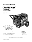
Owner's Manual
COMPANION I
5000 "Watt
AC Generator
Start
Model No. 580.327152
HOURS:
Mon.-
Fri. 8 aom. to 5 p.m. (CT)
CAUTION:
Before using this product, read this
manual and follow all Safety Rules
and Operating Instructions.
Sears, Roebuck and Co., Hoffman Estates, IL 60179
Visit our Craftsman website: www.sears.com
Part No, B2473 Draft 2 (6/18/1999)
Printed in the U,S.A.
•
•
•
•
°
Safety
Assembly
Operation
Maintenance
Parts
WARRANTY ...............................
SAFETY INSTRUCTIONS
....................
ASSEMBLY
...............................
OPERATION .............................
PRODUCT SPECIFICATIONS
................
MAINTENANCE
........................
2
3
4
5-9
10
t0-11
STO RAG E ...............................
TROUBLESHOOTING
......................
WIRING DIAGRAM .........................
REPLACEMENT PARTS ..................
EMISSIONS WARRANTY .................
HOW TO ORDER PARTS/SERVICE
LIMITED ONE YEAR WARRANTY
FOR COMPANION
12
13
!5
16-22
24-25
. .BACK PAGE
GENERATORS
SEARS warrants to the original purchaser that the alternator and engine for its portable generator wilt be free
from defects in materials or workmanship for the items and period set forth below from the date of original
purchase. This warranty is not transferable.
CONSUMER*
COMMERCIAL*
Alternator
1 year
90 Days
Engine
1 year
90 Days
* NOTE: For the purpose of this warranty "Consumer Use" means personal residential household and emergency
use by original purchaser, not to be Used as a primary source of power. "Commercial Use" means all other uses,
including rental, construction, commercial, and income producing purposes. Once a generator has experienced
commercial use, it shall thereafter be considered a commercial use generator for the purpose of this warranty.
During Said warranty period, SEARS witll at its optioni repair or replace any part which, upon examination by
: i SEARS, is found to be defective under norrnal use and service**. Starting batteries are not warranted by
SEARS. All transportation costs under warranty, including return to the factory if necessary, are to be borne by
the purchaser and prepaid by him. This warranty does not cover normal maintenance and service and does not
apply to a generator set, alternator or engine, o r parts which have been subjected to improper or unauthorized
installation or alteration, misuse, negligence, accident, overloading, over-speeding, improper maintenance, repair
or storage so as, in SEARS's judgment, to adversely affect its performance and reliability.
** NORMAL WEAR: As with all mechanical devices, engines need periodic parts service and replacement to
perform well. This warranty wit! not cover repair when normal use has exhausted the life of a part or engine.
THERE IS NO OTHER EXPRESS WARRANTY. SEARS HEREBY DISCLAIMS ANY AND ALL IMPLIED
WARRANTIES, INCLUDING BUT NOT LIMITED TO THOSE OF MERCHANTABILITY
AND FITNESS
FOR A PARTICULAR PURPOSE TO THE EXTENT PERMITTED BY LAW. THE DURATION OF ANY
IMPLIED WARRANTIES WHICH CANNOT BE DISCLAIMED IS LIMITED TO THE TIME PERIOD AS
SPECIFIED IN THE EXPRESS WARRANTY. LIABILITY FOR CONSEQUENTIAL,
INCIDENTAL, OR
SPECIAL DAMAGES UNDER ANY AND ALL WARRANTIES IS EXCLUDED.
Some provinces do not allow limitations on how long an implied warranty lasts, or the exclusion or limitation of
incidental or consequential damages, so the above limitations or exclusions may not apply to you. This warranty
gives you specific legal rights and you may also have other rights, which vary from state to state.
For service, see your nearest SEARS authorized warranty service facility. Warranty service can be performed
only by a SEARS authorized service facility. This warranty will not apply to service at any other facility. At the
time of requesting warranty service, evidence of original purchase date must be presented.
SEARS, ROEBUCK and CO., D/817WA, Hoffman Estates, IL 60179 U.S.A.
2
I
Gasoline is highly FLAMMABLE and its vapors are
EXPLOSIVE. Do not permit smoking, open flames,
sparks or heat in the vicinity while handling
gasoline. Avoid spilling gasoline on a hot engine.
contains chemicals known to the State
Comply with all laws regulating storage and
of California to cause cancer, birth
The engine exhaust fromthis pr0duCt :
handling of gasoline.
defects, or other reproductive harm_.............................
°
Never add fuel while unit is running.
@
CAUTION: Always disconnect spark plug
Do not overfill the fuel tank. Always allow room for
wire and place-the wire where it cannot
fLiel expansion. If tank is overfilled, fuel can
contact the spark plug. To prevent accidental
overflow onto a hot engine and cause FIRE or an
starting when setting up, transporting,
EXPLOSION.
adjusting or making rePairs to your
Never store generator with fuel in tank where
Generator.
gasoline vapors might reach an open flame or
spark or pilot light (as on a furnace, water heater or
DANGER: This generator is designed for
Clothes dryer). FIRE or an EXPLOSION might
outdoor use only. Do not use this generator
result.
inside any building or enclosure including the
- Generator exhaust gases contain DEADLY carbon
generator compartment of a recreational
monoxide gas. Operate this equipment only in the
vehicle (RV). Fire or an explosion may result.
open air where adequate ventilation is available.
No user performed modifications, including
venting of exhaust and!or cooling ventilation,
will eliminate the danger. Also, allow at least
two feet of clearance on all sides of the
generator even while operating the unit
outdoors.
CAUTION: Before using this product, read
this manual and follow all Safety Rules and
Operating Instructions.
•
The generator produces dangerously high voltage
that can cause extremely hazardous electrical
shock. Avoid contact with bare wires, terminals,
etc. Never permit any unqualified person to
operate or service the generator.
•
Never handle any kind of electrical cord or device
while standing in water, while barefoot or while
hands or feet are wet.
The National Electric Code requires the frame and
external electrically conductive parts of generator
be properly connected to an approved earth
ground. Local electrical codes may also require
proper grounding of the generator. Consult with a
local electrician for grounding requirements in your
area.
•
Use a ground fault circuit interrupter in any damp
or highly conductive area (such as metal decking
or stee! work).
•
Operate generator only on level surfaces and
where it will not be exposed to excessive moisture,
dirt, dust or corrosive vapors.
•
Do not use worn, bare, frayed or otherwise
damaged electrical cord sets with the generator.
i
°
The engine-generator requires an adequate flow of
cooling air for its continued proper operation.
Never operate the unit inside any room or
enclosure where the free flow of cooling air into
and out of the unit might be obstructed. Allow at
least 2 feet of clearance on all sides of generator,
even while operating unit outdoors, or you could
damage the unit.
=
Never start, or stop, the engine-generator with
electrical loads connected to receptacles with the
connected devices turned ON. Start the engine
and let it stabilize before connecting electrical
loads. Disconnect all electrical loads before
shutting down the generator.
°
Do not insert any object through cooling slots of
the engine-generator.
=
Never operate generator
(a) in rain;
(b) in any enclosed compartment;
(c) if connected electrical devices overheat;
(d) if electrica! output is lost;
(e) if engine or generator sparks;
(f) if flames or smoke are observed while unit is
running;
(g) if unit vibrates excessively.
Note; If you equip the engine with a spark arrestor
muffler, the spark arrestor must be maintained in
effective working order by the owner/operator.
In the State of California a spark arrestor is required by
law (Section 4442 of the California Public Resources
Code). Other states may have similar laws. Federal laws
apply on federal lands. The spark arrestor part number
for this unit is p/n 34479A.
LOOK FOR THISBECOME
SYMBOLALERT!!!
TO POINT
OUT SAFETY
IMPORTANT
SAFETY PRECAUTIONS. IT MEANS
"ATTENTION!!!
YOUR
IS INVOLVED."
J
Your generator requires some assembly and is ready
for use after it has been properly serviced with the
recommended oil and fuel.
•
::
o
If you have any problems with the assembly of
your generator, please call the generator helpline
at 1-800-222-3136
important: Any attempt to run the engine before it has
been serviced with the recommended oil will result in
an engine failure.
REMOVE
GENERATOR
Connect the black battery cable from the engine
mount bolt to the negative (-) battery post. Tighten
securely.
Red ¢abte
connected to
engl
switch here
FROM CARTON
•
Set the carton on a rigid flat surface with 'q-HIS
SIDE UP" arrows pointing upward.
•
Carefully open the top flaps of the shipping carton.
•
Cut down corners at one end of carton from top to
bottom and lay that side of carton down flat.
,
Remove all packing material, carton fillers, etc.
o
Remove the generator from the shipping carton.
CARTON
Secure battery as shown with bracket, (2) bolts, (2)
flat washers, (2) lock washers and (2) hex nuts.
\
CONTENTS
Check all contents, if any parts are missing or
damaged, call the Generator Helpline at
1-800-222-3136.
o The main unit
°
"
Electric start battery cables
Owner's manual
•
Engine oil
o
Battery mounting brackets
INSTALLING
8lack cabie
connected to
engine mount here
BATTERY
You must purchase and instalfa !2 Volt DC battery,
Series U1 Lawn & Garden Tractor battery (Sears
p/n 96135). The battery should be properly serviced
with electrolyte fluid and fully charged pnor to
installation.
_
•
Install the battery as follows:
°
Set the battery on the generator's battery tray.
4
CAUTION: to
connected
Bethe
sure
engine
the black
mountcable
and is
not the
frame. You could damage the ground wire.
Connect the red battery cable from the engine
starter switch to the positive (+) battery post.
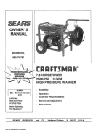
KNOW YOUR
GENERATOR
Read the owner's manual and safety rules before operating your generator.
Compare the illustration shown below with your generator to familiarize yourself with the locations of various
controls and adjustments. Save this owner's manual for future reference.
FuelTank
Muffler
Air Cleaner
Choke Lever
1201240 Volt AC, 20 Amp
Locking Receptacle
Oil Fill
Dipstick
/
Oil Drain Plug
/
120 Volt AC, 20 Amp
Duplex Receptacle
/
Grounding Wing Nut
120 Volt AC, 20 Amp, Duplex Receptacles -- May
be used to supply electrical power for the operation of
120 Volt AC, 20 Amp, single phase, 60 Hz electrical
lighting, appliance, tool and motor loads.
Battery Tray
Circuit Breakers
Choke Lever-
Used when starting a cold engine.
Circuit Breakers (AC) m Each receptacle is provided
with a circuit breaker to protect the generator against
electrical overload. Breakers are "push to reset" type.
120/240 Volt AC, 20 Amp Locking Receptacle
May be used to supply electrical power for the
operation of 120 and/or 240 Volt AC, 20 Amp, single
phase, 60 Hz electrical lighting, appliance, tool and
motor loads.
Fuel Tank m Tank holds 5 U.S. gallons of unleaded
gasoline.
Air Cleaner -- Filters intake air as it is drawn into the
engine.
Muffler -- Muffler lowers engine noise.
Battery Tray -- Insta!l battery here.
Oil Fill Dipstick
Grounding Wing Nut - Provides earth grounding point
for generator
Oil Drain Plug -- Drain engine oil here.
5
-- Fill engine with oil here.
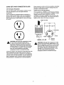
CORD SETS AND CONNECTOR
Keep extension cords as short as possible, preferably
tess than 15 feet long, to prevent voltage drop and
possible overheating of wires.
PLUGS ....
120 Volt Duplex Receptacle
120t240 Volt, 20 Amp Receptacle
Use only high quality, well-insulated, extension cords
with the generator's t20 Volt duplex electrical
receptacles.
This receptacle is a NEMA L14-20R and is protected
by a push-to-reset
circuit breaker. A NEMA L14-20P
mating connector plug is required to use this
receptacle. Connect a suitable 4-wire cord set to the
plug and to the desired load. The cord set should be
rated for 250 Volts at 30 Amps (or greater).
Each receptacle is protected against overload by a
push-to-reset circuit breaker. Use each receptacle to
operate 120 Volt AC, single phase, 60 Hz electrical
loads requiring up to 2400 watts (2.4 kW) at 20 Amps
of current.
4-Wire Cord Set
i_
240V
_--120V-->
<-- 120V-->
i
W (Neutral)
Y (Hot)
NEMA
CAUTION! Although each receptacle is rated
for 120 Volts at 20 Amps (2400 watts or
2.4 kW), the generator is rated for a total of
5000 watts. Powering loads that exceed the
wattage capacity of the generator can damage
it or cause serious injuries. The total of loads
with 120 Volts powered through these
receptacles should not exceed 20 Amps.
A
Check the ratings of all extension cords before you use
them. Extension cord sets used should be rated for
t25 Volts AC at 20 Amps or greater for most electrical
devices. Some devices, however, may not require this
type of extension cord. Check the owner's manuals of
those devices for manufacturer's recommendations.
6
L14-20
X (Hot)
Ground
(Green)
forAUTION!
240 VoltsAlthough
at 20 Amps
(4800 wattsisorrated
4.8
this receptacle
kW), the generator is rated for a total of 5000
watts (5.0 kW). Powering loads that exceed
the wattage capacity of the generator can
damage it or cause serious injuries. Loads
with 240 Volts powered through this
receptacle should not exceed 20 Amps.
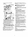
HOW TO USE YOUR GENERATOR
Place generator on a level surface.
If you have any problems operating your Generator,
please call the Generator hetpline at 1-800-222-3136.
= Clean area around oil fill and remove oil dipstick.
GROUNDING
°
o Wipe dipstick clean.
THE GENERATOR
The National Electrical Code requires that the frame
and external electrically conductive parts of this
generator be properly connected to an approved earth
ground. Local electrical codes may also require proper
grounding of the unit. For that purpose, a grounding
wing nut is provided on the base of the cradle.
Pour oil into oil fill opening until oil reaches FULL
mark on the dipstick Do not overfil!!
Add Gasoline
WARNING NEVER fill fuel tank indoors.
NEVER fill fuel tank when engine is running or
hot. DO NOT light a cigarette or smoke when
filling the fuel tank.
CAUTION: Do not overfi!l the fuel tank.
Always leave room for expansion.
regular UNLEADED gasoline with the
Generator engine. Do not use premium gasoline.
Do not mix oil with gasoline.
Grounding Wing Nut
=
Clean area around fuel fill cap, remove cap.
•
Add unleaded regular gasoline, slowly to fuel tank.
Be careful not to overfill. Allow about 1/2" of tank
space between bottom of fill opening and top of fuel
for fuel expansion.
-
Install fuel cap and wipe up any spilled gasoline.
Proper grounding of generator wilt help prevent
electrical shock in the event of a ground fault condition
in the generator or in connected electrical devices.
Proper grounding also helps dissipate static electricity,
which often builds up in ungrounded devices.
IMPORTANT: tt is important to prevent gum deposits
from forming in essential fuel system parts such as the
carburetor, fuel filter, fue! hose or tank during storage.
Also, experience indicates that alcohol-blended fuels
(called gasohol, ethanol or methanol) can attract
moisture which leads to separation and formation of
acids during storage. Acidic gas can damage the fuel
system of an engine while in storage. To avoid engine
problems, the fue! system should be emptied before
storage of 30 days or longer. See "Storage" on
page 12. Never use engine or carburetor cleaner
products in the fuel tank or permanent damage may
occur.
BEFORE
TO START
.Generally, connecting a No. 12 AWG (American Wire
Gauge) stranded copper wire to the grounding wing
nut and to an earth-driven copper or brass grounding
rod (electrode) provides adequate protection against
electrical shock. However, local codes may vary
widely. Consult with a local electrician for grounding
requirements in your area.
STARTING
THE GENERATOR
THE ENGINE
To operate the engine you must do the following:
A
Add Engine Oil
NOTE: When adding oil to the engine crankcase in the
future, use onIy high quality detergent oil rated with
API service classification SF or SG or higher rated
SAE 30 weight. Use no special additives. Select the
oil's viscosity grade according to your expected
operating temperature.
colder
_
5W30
32°F,, _
•
warmer
SAE 30
Although multi-viscosity oils (5W30, 10W30, etc.)
improve starting in cold weather, this type oil will result
in increased oil consumption when used above 32°F.
Check your engine oil level more frequently to avoid
possible damage from running low on oil
electrical devices
WARNING:
Never plugged
start or into
stop the
engine
panelwith
receptacles and turned on.
•
Unplug all electrical loads from generator
receptacles before starting the engine.
°
°
Make sure the unit is in a level position.
Open the fuel shut-off valve.
1
i
......-._ Fuel Tank
FuelValve--.._
"Open" PositionShown _/
t Turn Clockwise to
"OFF" Position
•
Note: If engine fires, but does not continue to run,
move choke lever to "Full Choke" and repeat starting
instructions.
Move the choke lever to the "Full Choke
Position,"
FULLCHOKEPOSITION
LEVER
CHOKEPOSITION
CAUTION! Never run engine indoors or in
enclosed poorly ventilated areas. Engine
exhaust contains carbon monoxide, an
odorless and deadly gas.
WARNING! temperature of muffler and nearby
areas may exceed 150°F (65°C). Avoid these
areas.
STOPPING
•
Set the engine control switch to the On (-)
Position.
THE ENGINE
•
Unplug all electrical loads from generator panel
receptacles. Never start or stop engine with
electrical devices plugged in and turned on.
•
Let engine run at no-load for several minutes to
stabilize the internal temperatures of engine and
generator.
Move engine control switch to Off (o) Position.
Close the fuel shut-off valve
•
•
CONNECTING
Engine
Control
Switch
•
•
Electric Start: Hold the engine starter switch on
the cradle down until the engine starts.
NOTE: Use short starting cYCleS (15 seconds per
minute) to avoid overheating starter.
•
Let engine stabilize and warm up for a few minutes
after starting.
,
•
Plug in and turn on the desired 120 and/or 240 Volt
AC, single phase, 60 Hz electrical loads.
Do not connect 240 Volt loads to the 120 Volt
duplex receptacles
Do not connect 3-phase loads to the receptacles.
°
Do not connect 50 Hz loads to the receptacles.
•
DO NOT OVERLOAD THE GENERATOR. Add up
the rated watts (or Amps) of all loads to be
connected at one time. This total should not be
greater than the rated wattage/amperage capacity
of the generator. See "Don't Overload the
Generator" on Page 9.
LOW OIL LEVEL SHUTDOWN
When engine starts, move choke lever to "1/2
Choke Position" until the engine runs smoothly
and then to "No Choke Position." if engine falters,
move choke lever to "1/2 Choke Position" until the
engine runs smoothly and then to "No Choke
Position."
LOADS
-
°
Manual Start: Grasp starter grip and pull s!owiy
until you feel some resistance. Then pull cord out
with rapid full arm stroke. Let rope return slowly. Do
not let rope "snap back" against starter.
ELECTRICAL
SYSTEM
Sensing Low Oil Level
tf the system senses a low oil level during operation,
the engine shuts down. If the engine shuts down by
itself and it has enough gasoline in the fuel tank, check
oil level.
Note: If engine fails to start after 3 pulls, move the
choke lever to "No Choke Position" and pull starter
rope again.
Restarting
If you attempt to restart the engine after such a
shutdown and have not corrected the engine oil level,
the engine will not start. Check the oil and refill
according to the instructions on page 7.
Note: If the engine fails to start after three (3) pulls,
check for proper oil level in crankcase. Unit is
equipped with a low oil shutdown system.
8
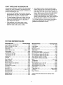
DON'T
OVERLOAD
THE GENERATOR
Overloading a generator in excess of its rated wattage
capacity can result in damage to the generator and to
connected electrical devices. Observe the following, to
prevent overloading the unit:
-
*
Add up the total wattage of ali electrical devices to
be connected at one time. This total should NOT be
greater than the generator's wattage capacity.
°
The rated wattage of lights can be taken from light
bulbs. The rated wattage of tools, appliances and
motors can usually be found on a data plate or
decal affixed to the device.
*
The Wattage Reference Guide below is provided to
assist you in determining how many items your
generator can operate at one time.
If the appliance, tool or motor does not give
wattage, multiply volts times ampere rating to
determine watts (volts x amps = watts).
WATTAGE
REFERENCE
Some electric motors, such as induction types,
require about two and a half times more watts of
power for starting than for running. This surge of
power lasts only a few seconds when starting such
motors. Make sure you allow for this high starting
wattage when selecting electrical devices to
connect to your generator. First, figure the watts
needed to star_ the largest motor. Add to that figure
the running watts of all other connected loads.
GUIDE
Electrical Device ..........
*Air Conditioner (t2,000 Btu)
Battery Charger (20 Amp)
Belt Sander (3")
Chain Saw
Circular Saw (6-1/2")
Coffee Maker
*Compressor (t HP)
*Compressor (3/4 HP)
*Compressor (1/2 HP)
Curling Iron
*Freezer
Disc Sander (9")
Edge Trimmer
Electric Nail Gun
Running Watts
1700
500
~1000
~1200
~800 to 1000
~1000
2000
~1800
-1400
700
500
~1200
500
-t200
Electric Range (one element)
Electric Skillet
*Furnace Fan (1/3 HP)
Hair Dryer
Hand Drill (1")
Hand Drill (1/2")
Hand Drill (3/8")
Hand Drill (t/4")
Hedge Trimmer
Impact Wrench
-1500
-1250
-1200
-t 200
-1100
750 to 1000
500
250
~450
500
Electrical Device
*Jet Pump
Lawn Mower
Light Bulb
Microwave Oven
*Milk Cooler
Oil Burner on Furnace
Running Wa_s
-800
~1200
-100
700
-1100
300
~400
Oil Fired Space Heater (140,000 Btu)
225
Oit Fired Space Heater (85,000 Btu)
-150
Oil Fired Space Heater (30,000 Btu)
600
*Paint Sprayer, Airless (1/3 HP)
~150
Paint Sprayer, Airless (handheld)
Radio
50to 200
*Refrigerator
-600
Slow Cooker
200
2800
*Submersible Pump (1-1/2 HP)
2000,
*Submersible Pump (1 HP)
-1500
*Submersible Pump (1/2 HP)
600
Sump Pump
*Table Saw (10")
~1750to 2000
Television
200to 500
Weed Trimmer
5OO
* Allow 3timesthelisted
devices.
9
wattsforstadingthese
Maintenance
Schedule
Follow the hourly or calendar intervals, whichever occurs first.
More frequent service is required when operating in adverse conditions noted below.
Every 5 Hours
or uaily
Maintenance Operation
25 Hours or
Every Season
50 Hours or
Every Season
100 Hours or
Every Season
Check oil level
WNNN
Change oil and oil filter_
x* '
Service air cleaner
Replace spark plug
Prepare unit for storage if it is to remain idle for more
Prepare Unit for storage
than 30 days
_:
Change oil after first 5 hours of operation then after every 25 hours or every season.
*
Change oit and oil filter sooner when operating under heavy load or in high temperatures.
**
Clean more often under dirty or dusty conditions.
PRODUCT
Note: Once a year you should clean or replace the
spark plug and replace the air filter. A new spark plug
and clean air filter assure proper fueFair mixture and
help your engine run better and last longer.
SPECIFICATIONS
Generator Specifications
Rated Maximum Power ........
Surge Power ................
Rated Voltage ...............
Rated Maximum Current
at 240 Volts ................
Rated Maximum Current
at 120 Volts ................
Rated Frequency ............
Phase .....................
5000 Watts (5.0 kW)
6250 Watts (6.25 kW)
120/240 Volts AC
GENERATOR
Generator maintenance consists of keeping the unit
clean and dry. Operate and store the unit in a clean
dry environment where it will not be exposed to
excessive dust, dirt, moisture or any corrosive vapors.
Cooling air slots in the generator must not become
clogged with snow, leaves, or any other foreign
material.
20.8 AC Amperes
41.7 AC Amperes
60 Hz at 3600 rpm
Single Phase
Check the cleanliness of the generator frequently and
clean when dust, dirt, oil, moisture or other foreign
substances are visible on its exterior surface.
Engine Specifications
Rated Horsepower ...........
Spark Plug
Type: ................
10 at 3600 rpm
Note: We DO NOT recommend using a garden hose
to clean generator. Water can enter the engine fuel
system and cause problems, tn addition, if water
enters the generator through cooling air slots, some of
the water will be retained in voids and cracks of the
rotor and stator winding insulation. Water and dirt
buildup on the generator internal windings will
eventually decrease the insulation resistance of these
windings.
Champion RJ17LM or
Equivalent
0.030inch (0.76mm)
5 U.S. gallons
Set Gap To: ...........
Gasoline Capacity ............
Oil
Summer SAE 30 (t0W-30)
Winter ..............
SAE 5W-20 or 5W-30
GENERAL
MAINTENANCE
RECOMMENDATIONS
CLEAN
The Generator warranty does not cover items that
have been subjected to operator abuse or negligence.
To receive full value from the warranty, operator must
maintain unit as instructed in this manual.
_
Some adjustments will need to be made periodically to
properly maintain your Generator.
All adjustments in the Service and Adjustments section
of this manual should be made at least once each
season. Follow the requirements in the "Maintenance
Schedule" chart above.
10
THE GENERATOR
through
the Never
air cooling
the
AUTION:
Insertslots,
any even
object if or
tool
engine is not running.
-
Use a damp cloth to wipe exterior surfaces clean.
,,
A soft, bristle brush may be used to loosen caked
on dirt, oil, etc.
o
A vacuum cleaner may be used to pick up Ioose dirt
and debris.
Low pressure air (not to exceed 25 psi) may be
used to blow away dirt. Inspect cooling air slots and
openings on the generator. These openings must
be kept clean and unobstructed.
ENGINE
_
,
Check electrode gap with wire feeler gauge and set
spark plug gap to 0.030 inch (0.76mm) if
necessary.
o
Replace spark plug if electrodes are pitted, burned
or porcelain is cracked.
MAINTENANCE
ANGER:
When working
on the
always
disconnect
spark plug
wiregenerator
from spark
plug and keep it away from spark plug.
Checking Oil Level
Oil level should be checked prior to each use or at
least every 5 hours of operation. Keep oil level
maintained.
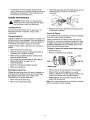
Service Air Cleaner
Your engine will not run properly and may be damaged
if you run it using a dirty air cleaner.
Changing Engine Oil
Change oil after first 5 hours of operation. Change oil &
oil filter every 25 hours thereafter, tf you are using your
generator under extremely dirty or dusty conditions, or
in extremely hot weather, change oil more often.
Change oil while engine is still warm from running, as
follows:
•
Clean area around oi! drain plug.
•
Remove oil drain plug and oil fill plug and drain oil
completely into a suitable container.
Clean or replace the air cleaner every 100 hours of
operation or once a year, whichever comes first. Clean
or replace more often if operating under dusty or dirty
conditions. Replacements are available at your local
Sears Authorized Service Center
To clean or replace
air cleaner follow these steps:
°
Remove wing nut.
•
Remove air cleaner cover carefully.
o When oil has completely drained, Install oil drain
plug and tighten securely.
•
Fill oil sump with recommended oil. (See "Before
Starting the Engine" on page 7 for oil
recommendations)
°
Install the oil fill plug and tighten securely.
•
Wipe up any spilled oil.
BASE_
NUT
PAPER
Clean/Replace Spark Plug
*
Remove the air filter and examine it for damage.
Change the spark plug every 100 hours of operation or
once each year, whichever comes first. This will help
your engine to start easier and run better. See
"Specifications" for proper spark plug.
o
Clean air filter by gently tapping it on a solid
surface. If the filter is too dirty, replace the filter with
a new one. Dispose of the old filter properly.
o
Reassemble all parts and fasten securely to the
engine with the wing nut.
o Clean area around spark plug.
°
Note: Do not use pressurized air or petroleum solvents
such as kerosene to clean cartridge.
Remove and inspect spark plug.
11
GENERAL
Change Oil
The generator should be started at least once every
seven days and allowed to run at least 30 minutes, if
this cannot be done and you must store the unit for
more than 30 days, use the following information as a
guide to prepare it for storage.
While engine is still warm, drain oil from crankcase.
Refill with recommended grade.
LONG TERM STORAGE
_
Oil Cylinder Bore
•
Remove spark plug and pour about 1/2 ounce
(15ml) of engine oil into the cylinder. Cover spark
plug hole with rag, Crank slowly to distribute oil.
INSTRUCTIONS
tank
indoors NEVER
or in enclosed,
poorly with
ventilated
ARNING:
store engine
fuel in
areas where fumes may reach an open flame,
spark or pilot light as on a furnace, water
heater, clothes dryer or other gas appliance.
,_
-
Install spark plug. Do not connect spark plug wire.
GENERATOR:
It is important to prevent gum deposits from forming in
essential fuel system parts such as the carburetor, fuel
filter, fuel hose or tank during storage. Also,
experience indicates that alcohol-blended fuels (called
gasohol, ethanol or methanol) can attract moisture
which leads to separation and formation of acids
during storage. Acidic gas can damage the fuel system
of an engine while in storage.
•
Clean the generator as outlined on page 10 ("Clean
the Generator").
°
Check that cooling air slots and openings on
generator are open and unobstructed.
OTHER STORAGE
To avoid engine problems, the fuel system should be
emptied before storage of 30 days or longer. Follow
these instructions:
Do not store gasoline from one season to another.
°
Replace your gasoline can if your can starts to rust.
Rust and/or di_ in your gasoline will cause
problems.
-
If possible, store your unit indoors and cover it to
give protection from dust and dirt. BE SURE TO
EMPTY THE FUEL TANK.
WARNING: Drain fuel into approved
container outdoors, away from open flame. Be
sure engine is cool. Do not smoke.
o
TIPS:
°
Protect Fuel System
•
when
cranking
engine
CAUTION!
Avoid
sprayslowly.
from spark plug hole
Cover your unit with a suitable protective cover that
does not retain moisture.
Store generator in clean, dry area,
Remove all gasoline from the fuel tank to prevent
gum deposits from forming on these parts and
causing possible malfunction of engine.
,_
Run engine until engine stops from lack of fuel.
12
while
engineNEVER
and exhaust
area Generator
are warm.
DANGER:
cover your
PROBLEM
Engine is running,but no
AC output is available,
Engine runsgoodat no-toadbut "bogs
down"when loadsare connected
CAUSE
CORRECTION
t, One of the circuitbreakersisopen.
2, Faultin generator.
3, Poorconnectionor defective
cordset.
4, Connecteddeviceis bad.
1. Resetcircuitbreaker.
2.Contact SearsService Facility,
3.Checkand repair.
1, Shortcircuitin a connectedload.
I. Disconnect
shorted electrical
load.
2.Contact SearsService Facility,
3.See "Don'tOverloadthe
Generator'>,page 9.
4.Contact SearsServiceFacility.
2, Enginespeedis tooslow,
3. Generatoris overloaded.
4, Shortedgeneratorcircuit.
Enginewill not start;or starts
and runs rough.
4.Connectanotherdevice that
is in good condition.
1, Run/StopSwitchset to STOP,
2. Dirtyair cleaner
3, Out of gaso!ine.
4. Stalegasoline,
5. Sparkplugwirenot connected
to spark plug.
6, Badspark plug.
7. Waterin gasoline,
8. Overchoking,
9. Lowoit level
10,Excessivelyrichfuel mixture,
11.Intakevalvestuck openor closed.
t 2,Enginehas lost compression,
6.Replacespark plug.
7. Draingas tank;fill withfresh fuel.
8. Open chokefully and crank engine.
9. Fillcrankcaseto properlevel.
!0. ContactSears ServiceFacility.
11. ContactSears ServiceFacility.
12. ContactSearsService Facility,
Engineshutsdownduringoperation
1,Out of gasoline,
2. Lowoit level.
1.Fill fuel tank,
2. Fill crankcaseto proper level.
Enginelackspower,
1. Load is toohigh,
2. Dirtyair filter.
1.See "Don't Overloadthe Generator"
2. Replaceair filter.
Engine "hunts"or falters.
1, Chokeis openedtoo soon,
1.Movechoke to halfwaypositionuntil
engine runssmoothly.
2.Contact SearsServiceFacility.
2, Carburetoris runningtoo rich
or too lean.
13
1.Set switch to RUN.
2.Clean or replaceair cleaner.
3.Fill fuel tank.
4.Drain gastank; fill with fresh fuel.
5.Connectwire to spark plug.
14
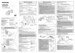
CRAFTSMAN
5000 Watt AC Generator
580.327152
Wiring Diagram
_o
©
<_
O
w
L_
F-
.or.
(F. rw_
U
i== ='-"
_x"
w,_=
W
W
I
GD
CO
C
15
_J
l_v-_.
-'t...l*
..,F-_
I_
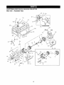
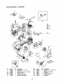
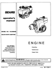
CRAFTSMAN
Main Unit-
5000 Watt AC Generator
Exploded
580.327152
View
,79
76
80
72
3O
73
STARTER DETAIL
78
900
32
54
'4
t
10
7
8
t
\.
12
54
48
/
4
\
!2
47 47
84
43
48
23
'A'
24
57
16
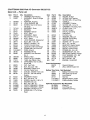
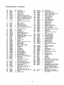
CRAFTSMAN
Main Unititem
2
3
5000 Watt AC Generator
Parts List
Part #
66825B
91825
Qty.
t
1
66365D
22129
86307
1
2
4
7
8
9
10
tl
12
t3
14
15
16
17
18
19
20
23
24
74716J
65791
67451
75431
B2762J
81917
86308C
27482
39414
70642
B3104
52858
76222
143-53621
38150
23365
1
1
1
1
1
1
4
1
1
2
1
7
2
1
6
4
26
27
28
30
78951B
56892
77374
78831B
1
2
1
4
31
32
33
34
38
39
90878
77395
78299
80270
68867
68759
1
4
1
!
1
1
40
41
42
43
44
45
46
47
48
84242
45771
74908
22264
51715
94396B
94396B
26850
75475
2
2
4
4
4
1
1
2
4
4
5
6
580.327152
Description
CARRIER, Rear Bearing
ASSEMBLY, Brush & Bridge
Rectifier
ADAPTER, Housing
LOCK WASHER, M8
SCREW, Hex Hd 5/16-24 x
3/4 Seres
ASSEMBLY, Rotor
BEARING
WASHER, Special
BOLT, Rotor
ASSEMBLY, Stator
PIN, Roll M4 x 10 Lg.
BOLT, Stator
LOCK WASHER, Shakeproof
BOLT, M8 - 1.25 x 35
MOUNT, Vibration - 45 °
COVER, Control Panel
LOCK NUT, M8-1.25 Flange
PPHMS, M8-1.25 x 40 mm
WIRE, Ground
WASHER, #8 Flat
WASHER, Lock Serrated
No. 8
SHIELD, Heat
10-24 x 3/8 Lg. Cfimptite
TANK, Gas Plastic 5 Gal.
CAPSCREW, Hex Hd. M6 x
60 mm BIk
CAP, Fuel Tank
NUT, Hex Lock _ M6
BUSHING, Plastic Tank
VALVE, Plastic Tank
OUTLET, 120/240 Twist Lock
OUTLET, 120 Volt 20amp.
Duplex
GROMMET, Rubber
NUT, Hex 5/16 - 18
SCREW, Hex M5 - 0.80 x 10
WASHER, #8 Lock
NUT, Hex - M4 - 0.7
CIRCUIT BREAKER - 20Amp
CIRCUIT BREAKER - 20Amp
WASHER, Shakeproof 1/4"
SCREW, M4 - 0.7 x 10 Pan
Head
Item
49
50
51
53
54
57
63
65
72
73
Part #
85652
82308
86494
B1635B
67022
66849
83465
48031C
92982
93826
74
76
77
78
79
80
81
82
83
84
85
86
87
88
89
900
68740
22097
75494
77282
22287
22127
78289
B3049
98247
75477
23762
65795
23897
49226
51716
NSP
Qty. Description
2
6
1
1
1
2
4
3
1
1
1
2
2
1
2
2
t
1
1
1
1
1
1
1
1
1
Parts Not Illustrated
B2473
t
NSP
1
Battery Tray Parts
44951
45000
22097
22127
113-53621
! 13-53621
Owner's Manual
28oz. SAE30 Engine Oil
- Not Illustrated
1
Battery Hold Down Bar
2
Hex Head Cap Screw
2
Lock Washer
Hex Nut
2
1
Negative Battery Cable
1
Positive Battery Cables
Optional Accessories
09-32684
09-32688
09-32686
17
MOUNT, Rubber
SCREW, Self Tapping
SCREW, M6 x 16 Lg. Wing
CRADLE
GROMMET, Rubber
SCREW, M5 - 0.8 x 15
GROMMET, Mounting Tank
CLAMP, Hose - 1/4"
DECAL, Danger
DECAL, Operating
Instructions
FILTER, Fue!
WASHER, M6 Lock
SCREW, Self Drilling
SWITCH, Starter
SCREW, 1/4" - 20 x 3/4"
NUT, 1/4" - 20 Hex
BRACKET, Starter Switch
DECAL, Panel Control
DECAL, Control Panel
PPHMS, M5 - 0.8 x 20
SHAKEPROOF, Ext. #10
RECTIFIER, Battery Charge
FLAT WASHER, #10 - M5
LOCKWASHER, M5
NUT, Hex M5 _ 0.8
ENGINE, 143.981007
Not lllustrated
WheeIKit
Co_W_p
Kit
120/240V 20A Plug
Tecumseh
Engine - 143.981007
+
36t
\
_€_
,, 36t
40O
!
416
I
1
[
65
75 7'
/
87
70
69
101
/
/
25
26
182
184 <_
276
380
277
178
1t
238
/
23g
110A
240
I
I
!_.__,_
251
_ I
285
• 9001
Item
1
2
t5
15A
15B
16
17
Part #
35968A
27652
30699C
30700
650494
33454A
29916
Qty
t
2
1
1
1
1
1
327
3gO
J
287
Item
18
20
25
25A
26
28
30
Description
Cylinder (incl. 2, 20 & 72)
Dowel Pin
Governor Rod (incL 15A &lSB)
Governor Yoke
Screw, 6-40 x 5/16"
Governor Lever Ass'y.
Governor Lever Clamp
18
Part #
651028
35319
35460
36244
650561
30322
35441A
Qty
1
1
1
1
2
1
1
Description
Screw, Torx T-15, 8+32 x3.8"
Oil Seal
Blower Housing Baffle
Air Baffle
-Screw, 1/4-20 x 5/8"
Lock Nut, 8-32
Camshaft
Tecumseh
Engine - 143.981007
Item
35
36
37
38
40
40
40
41
41
Part #
29826
29918
29216
29642
35776A
35777A
35778A
35773A
35774A
Qty
1
t
1
I
1
t
1
t
1
4I
35775A
t
42
42
42
43
45
35779
35780
35781
35772
36898
1
1
1
2
1
47
48
49
50
60
65
69
70
71
72
75
80
81
82
83
84
86
87
89
90
92
93
94
95
96
100
101
102
103
t 10
110A
111
65!033
34034
36896
35375
33273A
650128
35262A
35376
35377
27642
35319
31845
30590A
35378
30588A
29193
650833
650832
32589
611091
650880
650881
651016
30886A
30845A
35135
610118
65t024
651007
65589
36993
61 t206
2
2
1
1
1
1
1
1
1
2
1
1
1
1
1
1
7
1
1
1
1
1
1
1
1
1
1
2
2
1
1
1
111B
112
113
1t9
120
125
t25
611224
35967
650950
36451
36449
27878A
27880A
1
1
4
1
1
1
t
I26
126
t27
128
34035
34036
650691
650690
1
1
9
9
Description
Screw, 10-32 x 3/4"
Lock Washer
Lock Nut, 10-32
Retaining Pin
Piston, Pin & Ring Set (Std.!,
Piston, Pin & Ring Set (.010 OS)
Piston, Pin & Ring Set (.020 OS)
Piston & Pin Ass'y (Std.) (Incl. 43)
Piston & Pin Ass'y (.010" OS)
(incl. 43)
Piston & Pin Ass'y (.020") (Incl.
43)
Ring Set (Std.)
Ring Set (.010" OS)
Ring Set (.020" OS)
Piston Pin Retaining Ring
Connecting Rod Ass'y. (Incl. 47 &
49)
Connecting Rod Bolt
Valve Lifter
Oil Dipper
Camshaft (MCR)
Blower Housing Extension
Screw, 10-24 x 1/2"
Cylinder Cover Gasket
Cylinder Cover (incl. 71, 75 & 80)
Crankshaft Bushing
Oil Pipe Plug
Oil Seal
Governor Shaft
Washer
Governor Gear Ass'y. (Incl. 81)
Governor Spool
Retaining Ring
Screw, 1/4-20 x 1-3/16"
Screw, 1/4-20 x 1-11/16"
Flywheel Key
Flywheel
Lock Washer
Flywheel Nut
Lock Nut, 10-32
Extension Spring
R.P.M. Adjusting Bolt
Solid State Ignition
Spark Plug Cover
Solid State Mounting Stud
Screw, Torx T-15, 10-24 x 15/16"
Ground Wire
Ground Wire
Low Oil Shut-Down Switch
(incl. 112)
Rocker On/Off Switch
Low Oil Shutdown Gasket
Screw, Torx T-25, 10-24 x 5/8"
Cylinder Head Gasket
Cylinder Head
Exhaust Valve (Std.!, (Incl. 151)
Exhaust Valve (t/32 OS)
(Incl. t51)
lntake Valve (Std,) (fncL 151)
intake Valve (1/32" OS) (IncL 151)
Washer
Belleviile Washer
19
Item
130
130B
135
139
140
149
149A
150
151
169
170
171
172
173
173A
174
178
182
184
185
207
223
Part #
650694A
65103t
33636
33369
650836
27882
35862
27881
32581
27896A
28423
28424
28425
36675A
32446
650128
29752
30088A
33263
33877
33878
650378
Oty
9
1
1
1
2
1
1
2
2
2
1
1
1
1
2
2
2
2
1
1
1
2
224
238
239
240
242
245
250
251
260
261
262
27915A
28820
27272A
37104
33267
33268
33269A
650513
36243A
650788
29747B
1
2
1
1
1
1
t
t
1
2
2
264A
265
275
276
277
285
287
290
292
311
312
324
325
327
342
361
370G
380
390
395
400
650802
33272B
34t85B
31588
650729
35985B
29752
30705
26460
35941
29673
33177
29443
35392
30063
650990
35274
640129
590746
36680
36454
1
1
1
1
2
1
4
1
2
1
1
I
1
1
1
4
1
1
1
1
1
416
900
34479A
NSP
I
1
Description
Screw, 5/16-18 x 2"
Screw, 1/4-20 x 9/16"
Resistor Spark Plug (RJ17LM)
Governor Gear Bracket
Screw, 10-24 x 1/2"
Valve Spring Cap
Valve Spring Cap
Valve Spring
Valve Spring Keeper
Valve Cover Gasket
Breather Body
Breather Element
Valve Cover
Breather Tube
Breather Tube Grommet
Screw, 10-24 x 1/2"
Nut &:' Lock Washer, 1/4-28
Screw, 1/4-28 x 1"
Carburetor to Intake Pipe Gasket
Intake Pipe
Throttle Link
Screw, Torx T-30, 5/16-18 x
t-t/8"
Intake Pipe Gasket
Screw, 10-32 x 1/2"
Air Cleaner Gasket
Air Cleaner Bracket
Air Cleaner Bracket
Air Cleaner Filter
Air Cleaner Cover
Wing Nut, 1/4-20
Blower Housing
Screw, 5/16-18 x 3/4"
Screw, Torx "1"-40,5/16-24 x
21/32"
Screw, 1/4-20 x 518"
Cylinder Head Cover
Muffler
Locking Plate
Screw, 5.16-18 x 3-3/16
Starter Cup
Nut & Lock Washer, 1/4-28
Fuel Line
Fuel Line Clamp
Dipstick (incl. 312)
"O" Ring
Terminal
Wire Clip
Starter Plug
Screw, Torx T-30, I/4-20 x 1/2"
Screw, Torx T-30, 1/4-20 x 15/32"
Oil Instruction Decal
Carburetor (incl. 184)
Rewind Starter
Electric Starter Motor (12 Volt)
Gasket Set (Inc!. part #'s 27272A
(1), 27896A (2), 27915A (I),
29673 (1), 33263 (1), 33629 (1),
34698A (1), 35262 (1), 35317 (1),
36451 (t)
Spark Arrestor Kit (Optional)
Rep. Short Block 756282B, Order
from 71-999
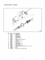
Tecumseh
Engine - 143.981007
Item
0
1
1
20
Part #
640129
Qty
1
631776A
1
2
4
5
6
7
t0
631970
631184
631183
64O109
650506
632597
1
1
1
1
2
1
ti
12
13
14
15
16
17
632043
631184
631183
631753
630735
632164
651025
1
1
1
1
1
1
1
18
20
20A
25
27
28
29
30
630766
640027
640053
631867
631024
632019
631028
63t 021
1
1
1
1
1
1
1
1
31
36
37
40
44
47
48
631022
640113
632547
640114
27110
630748
631027
1
1
2
1
1
1
1
Description
Carburetor (incl. 184 of
Engine Parts List)
Throttle Shaft & Lever
Assembly
Throttle Return Spring
Dust Seal Washer
Dust Seal (Throttle)
Throttle Shutter
Shutter Screw
Choke Shaft and Lever
Assembly
Choke Return Spring
Dust Seal Washer
Dust Seal (Choke)
Choke Shutter
Choke Positioning Spring
Fuel Fitting
Throttle Crack Screw/Idle
Speed Screw
Tension Spring
idle Restrictor Screw
Idle Restrictor Screw Cap
Float Bowl
Float Shaft
Float
Float Bowl "0" Ring
Inlet Needle, Seat & Clip
(Incl. 3t)
Spring Clip
Main Nozzle Tube
"O" Ring, Main Nozzle Tube
High Speed Bowl Nut
Bowl Nut Washer
Welch Plug, Idle Mixture Well
Welch Plug, Atmospheric
Vent
Tecumseh
Engine - 143.981007
Item
0
1
2
3
4
5
6
7
8
9
!0
t2
14
15
16
17
18
20
Pad #
36680
33451
33842
33430
33854
33432
35893
33450
35894
35895
36699
35896
35897
35898
35899
650168
65O864
650990
Qty
1
1
1
1
1
t
1
2
I
t
t
1
1
2
1
1
2
4
Description
Electric Starter
Dust Cover
Retainer Ring
Spring Retainer
Anti-Drift Spring
Gear
Nut and Retainer Ring (incl. 2)
Lock Nut
Drive End Cap Ass'y
Armature
Housing Ass'y
Brush and Spring Kit
Thrust Washer
Bolt, 10-32 x 4-11/64"
End Cap & Brush Card Ass'y. (incl. 12, 14, t7, 18)
Washer
Nut
Screw, Torx T-30, 1/4-20 x 15/32"
21
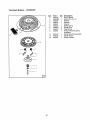
Tecumseh
Engine - 143.981007
0
1
2
3
4
5
6
7
8
PaN #
590746
590599A
590600
590679
590601
590678
590680
590412
590681
11
12
13
590747
590535
590701
Item
13
_8
F
22
Qty Description
1
1
1
1
1
1
2
2
1
1
1
1
Recoil Starter
Spring Pin (incf, 4)
Washer
Retainer
Washer
Brake Spring
Starter Dog
Dog Spring
Pulley & Rewind Spring
Assembly
Starter Housing Assembly
Starter Rope
Starter Handle
23
For California residents only when seeking service in California.
CALIFORNIA
YOUR
EMISSION
WARRANTY
CONTROL
RIGHTS
WARRANTY
STATEMENT
AND OBLIGATIONS
The California Air Resources Board ("CARB") and Sears Roebuck and Co., USA, are pleased to explain the
Emission Control System Warranty on your 1995 and later lawn and garden equipment engine. In California new
utility and lawn and garden equipment engines must be designed, built and equipped to meet the State's
stringent anti-smog standards. Sears must warrant the emission control system on your lawn and garden
equipment engine for the periods of time listed below provided there has been no abuse, neglect, or improper
maintenance of your lawn and garden equipment engine.
Your emission control system includes parts such as the carburetor and the ignition system.
Where a warrantable condition exists, Sears will repair your lawn and garden equipment engine at no cost to
you. Expenses covered under under warranty include diagnosis, parts, and labor.
MANUFACTURER'S
WARRANTY
COVERAGE
The 1995 and later utility and lawn and garden equipment engines are warranted for two years. If any emission
related part on your engine (as listed below) is defective, the part wilt be repaired or replaced by Sears.
OWNER'S
WARRANTY
RESPONSIBILITIES
As the lawn and garden equipment engine owner, you are responsible for the performance of the required
maintenance listed in your owners manual. Sears recommends that you retain all receipts covering maintenance
on your lawn and garden equipment engine, but Sears cannot deny warranty solely due for the lack of receipts or
for your failure to ensure the performance of all scheduled maintenance.
As the lawn and garden equipment engine owner, you should be aware that Sears may deny you warranty
coverage if your lawn and garden equipment engine or a part of it has failed due to abuse, neglect, improper
maintenance, unapproved modifications, or the use of parts not made or approved by the original equipment
manufacturer.
You are responsible for presenting your lawn and garden equipment engine to a Sears authorized repair center
as soon as a problem exists. Warranty repairs should be completed in a reasonable amount of time, not to
exceed 30 days.
If you have any questions regarding your warranty rights and responsibilities,
authorized service center or call Sears at 1-800-473-7247.
WARRANTY
COMMENCEMENT
you should contact your nearest
DATE
The warranty period begins on the date the lawn and garden equipment engine is delivered.
LENGTH
OF COVERAGE
Sears warrants to the initial owner and each subsequent purchaser that the engine is free from defects in
materials and workmanship which cause the failure of a warranted part for a period of two years.
24
WHAT
IS COVERED
REPAIR
OR REPLACEMENT
OF PARTS
Repair or replacement of any warranted part will be performed at no charge to the owner at an approved
Sears servicing center.
tf you have any questions regarding your warranty rights and responsibilities,
nearest authorized service center or call Sears at 1-800-473-7247.
WARRANTY
your shoutd contact your
PERIOD
Any warranted part which is not scheduled for replacement as required maintenance, or which is scheduled only
for regular inspection to the effect of "repair or replace as necessary" shall be warranted for 2 years. Any
warranted part which is scheduled for replacement as required maintenance shall be warranted for the period of
time up to the first scheduled replacement point for that part.
DIAGNOSIS
The owner shall not be charged for diagnostic labor which leads to the determination
defective if the diagnostic work is performed at an approved Sears servicing center.
CONSEQUENTIAL
that t warranted part is
DAMAGES
Sears may be liable for damages to other engine components caused by the failure of a warranted part still under
warranty.
WHAT IS NOT COVERED
All failures causedby abuse, neglect, or impropermaintenanceare notcovered.
ADD-ON
OR MODIFIED
PARTS
The use of add-on or modified parts can be grounds for disallowlng a warranty claim. Sears is not liable to cover
failures of warranted parts caused by the use of add*on or modified parts.
HOW TO FILE A CLAIM
If you have any questions regarding your warranty rights and responsibilities,
authorized service center or call Sears at 1-800-473-7247.
WHERE TO GET WARRANT'{
you should contact your nearest
SERVICE
Warranty services or repairs shall be provided at at! Sears authorized service centers.
MAINTENANCE,
REPLACEMENT
AND
REPAIR
OF EMISSION
RELATED
PARTS
Any Sears approved replacement part used in the performance of any warranty maintenance or repair on
emission related parts will be provided without charge to the owner if the part it under warranty.
EMISSION
CONTROL
WARRANTY
PARTS
LIST
1. Carburetor Assembly
2, Ignition System
a.
Spark Plug, covered up to maintenance
schedule.
b.
ignition Module
3. Crankcase Breather Tube
4. Exhaust Manifold
25
For in-home major brand repair service:
Call 24 hours a day, 7 days a week
1-800-4-MY-HOME
(1-800-469-4663)
Para pedir servicio de reparacibn a domicilio - t-800-676-5811
in Canada for all your service and parts needs call
- 1-800-665-4455
Au Canada pour tout le service ou les pi_ces
For the repair or replacement parts you need:
Call 7 am - 7 pro, 7 days a week
1-800-366-PART
(1-800-366-7278)
Para ordenar piezas con entrega a domicilio - 1-800-659.7084
For the location of a Sears Parts and Repair Center in your area:
Call 24 hours a day, 7 clays a week
1-800-488-1222
For information on purchasing a Sears Maintenance Agreement
or to inquire about an existing Agreement:
Call 9 am - 5 pm, Monday-
Saturday
1-800-827-6655
1/11
l[ IHIHIU ......
......
TheServiceSideof Sears
_