1
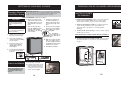
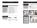
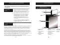
Keg Cooler
The model number can be found on the serial plate located on the
back panel of the unit.
Model • Modèle• Modelo
DCK646BLS
For service, contact your nearest
service depot or call:
1-800-26- Danby
(1-800-263-2629)
R
to recommend a depot in
your area.
All repair parts available for purchase or special order when you visit
your nearest service depot. To request service and/or the
location of the service depot nearest you, call the TOLL FREE
NUMBER.
When requesting service or ordering parts, always provide the
following information:
Model • Modèle• Modelo
Le numéro du modèle se trouve sur la plaque d'identification située
sur le panneau arrière de l'appareil.
1-800-26- Danby
(1-800-263-2629)
R
pour connaître le service
après-vente le plus proche.
Il est possible d'acheter les pièces de rechange ou de les obtenir par
commande spéciale en vous rendant à votre service après-vente le
plus proche. Pour effectuer des réparations ou obtenir l'adresse du
service après-vente le plus proche, veuillez composer le NUMÉRO
SANS FRAIS.
Pour effectuer des réparations ou commander des pièces de
rechange, veuillez donner les renseignements suivants :
• Type de modèle
• Numéro du modèle
• Description des pièces
Para obtener servicio,
comuníquese con el
establecimiento de servicio
más cercano o llame al:
1-800-26- Danby
(1-800-263-2629)
GUIDE D’UTILISATION
MANUAL DEL
PROPIETARIO
• Product Type
• Model Number
• Part Description
Glacière de bière en fût
En cas de réparation, veuillez
contacter votre service
après-vente le plus près ou
communiquez au:
OWNER’S MANUAL
DKC646BLS
CAUTION:
Read and follow all safety rules
and operating instructions
before first use of this product.
PRÉCAUTION :
Veuillez lire attentivement les
consignes de sécurité et les
instructions d'utilisation avant
l'utilisation initiale de ce
produit.
Refrigerador de Barril
R
para que le recomendemos un
establecimiento de su zona.
El número de modelo se encuentra en la placa de serie, ubicada en
el tablero posterior de la unidad.
Puede comprar todos los repuestos o hacer un pedido especial
visitando el establecimiento de servicio más cercano a su domicilio.
Llame al TELÉFONO GRATUITO para obtener servicio de
mantenimiento o la dirección del establecimiento de servicio más
cercano a su domicilio.
Siempre, al solicitar servicio de mantenimiento o hacer un pedido de
repuestos, debe suministrar la siguiente información:
• Tipo de artefacto
• Número de modelo
• Descripción del repuesto
PRECAUCIÓN:
Lea y observe todas las
reglas de seguridad y las
instrucciones de operación
antes de usar este producto
por primera vez.
Keg Cooler
Owners Manual
Table of Contents . . . . . . . . . . . . . . . . . . . . . . . . 3
Glacière de bière pression
Guide d'utilisation
Table des matières . . . . . . . . . . . . . . . . . . . . . ..23
Barril Refrigerador
Manual del propietario
Tabla de Contenido . . . . . . . . . . . . . . . . . . . . . . . . . ..43
?
R
Danby Products Limited, Guelph, Ontario Canada N1H 6Z9
Danby Products Inc., Findlay, Ohio USA 45840
Printed in China (P.R.C.)
Imprimé en Chine (R.P.C.)
Impresso en China (R.P.C.)
Danby Products Limited, Guelph, Ontario Canada N1H 6Z9
Danby Products Inc., Findlay, Ohio USA 45840
draft.1.03.07
WELCOME
GARANTÍA LIMITADA
Este producto de calidad está garantizado contra defectos de fabricación, incluyendo partes y mano de obra, siempre y cuando la unidad se utilice bajo las
condiciones normales de funcionamiento para las que fue diseñado.
Esta garantía está solamente disponible para la persona que haya comprado originalmente esta unidad directamente de Danby o uno de sus distribuidores
autorizados, y no es transferible.
CONDICIONES DE LA GARANTÍA
Las partes plásticas (como la puerta del evaporador, rieles de la puerta, cubiertas y bandejas) tienen una garantía de treinta (30) días a partir de la fecha de
compra, sin ninguna excepción.
Primeros Dos Años
Durante los primeros dos (2) años, cualquier parte eléctrica de este producto que resulte defectuosa, incluyendo cualquier sistema
sellado, será reparado o reemplazado, a opción del fabricante, sin cargo para el comprador ORIGINAL. Los insumos (como lámparas
eléctricas) no están garantizadas por ningún período de tiempo.
Para obtener Servicio Comuníquese con el distribuidor donde haya comprado la unidad, o llame al Taller de Servicio Autorizado más cercano, donde debe ser
reparada por un técnico calificado. Si esta unidad es reparada en otro lugar que no sea un Taller de Servicio Autorizado, o si la unidad se
utiliza para aplicaciones comerciales, Danby no se hará responsable de ninguna forma y la garantía será anulada.
Ninguna parte de esta garantía implica que Danby se hará responsable por el daño de ningún alimento u otros contenidos de este
artefacto, ya sea debido a un defecto del artefacto, o a su uso, ya sea apropiado o no.
EXCLUSIONES
Salvo lo aquí indicado por Danby Products Limited (Canadá) o por Danby Products Inc. (U.S.A.), no existen otras garantías, condiciones o representaciones,
explícitas o implícitas, concretas o intencionales por parte de Danby Products Limited o sus distribuidores autorizados y todas las demás garantías, condiciones
o representaciones, incluyendo cualquier garantía, condiciones o representaciones bajo cualquier Acta de Venta de Productos o legislación o estatuto similar,
quedan de esta forma expresamente excluidas. Salvo lo aquí indicado, Danby Products Limited (Canadá) o Danby Products Inc. (U.S.A.) no serán responsables
por ningún daño a personas o bienes, incluyendo la propia unidad, sin importar su causa, o de ningún daño indirecto causado por el desperfecto de la unidad, y
al comprar esta unidad, el comprador acepta por la presente, indemnizar y proteger a Danby Products Limited contra cualquier reclamo por daños a personas o
bienes causados por la unidad.
CONDICIONES GENERALES
No se considerará ninguna de estas garantías o seguros cuando el daño o la necesidad de reparación sea el producto de los siguientes casos:
1) Falla del suministro eléctrico.
2) Daños en tránsito o durante el transporte de la unidad.
3) Alimentación incorrecta, como bajo voltaje, instalación eléctrica defectuosa o fusibles inadecuados.
4) Accidente, modificación, abuso o uso incorrecto del artefacto, tal como no suficiente ventilación del ambiente o condiciones de operación anormales
(temperatura ambiente extremadamente alta o baja).
5) Utilización comercial o industrial.
6) Incendio, daños por agua, robo, guerra, disturbios, hostilidades, actos de fuerza mayor como huracanes, inundaciones, etc.
7) Pedidos de servicio debido a desinformación del usuario.
Para acceder a la garantía se solicitará un comprobante de compra; por lo tanto, guarde su recibo. En caso de necesitar servicio de garantía, presente ese
documento al TALLER DE SERVICIO AUTORIZADO
En Domicilio
03/08
61
You’ll see it in this
easy-to-use manual
and you’ll hear it in
the friendly voices of
our consumer service
department.
Tel: 1-800-26R
Danby Products Inc.
P.O. Box 669, Findlay, Ohio, U.S.A. 45839-0669
Teléfono: (419) 425-8627 FAX: (419) 425-8629
Best of all, you’ll
experience these
values each time you
use your Keg Cooler.
That’s important,
because your new
Keg Cooler will be
part of your family for
a long time.
Start Here!…Before using your Keg Cooler
Write down the model and serial
numbers here. They are on a label
located on the back of the cabinet.
Staple your receipt to the inside
back cover of this page. You will
need it to obtain service under
warranty.
Model number DKC646BLS
Serial number
Date purchased
NEED HELP?
Before you call for service,
there are a few things you
can do to help us serve
you better...
Read this manual
It contains instructions to
help you use and maintain
your keg cooler properly.
If you received a
damaged appliance
Immediately contact the
dealer (or builder) that sold
you the appliance.
Servicio de Garantía
Danby Products Limited
P.O. Box 1778, Guelph, Ontario, Canada N1H 6Z9
Teléfono: (519) 837-0920 FAX: (519) 837-0449
Welcome to the
Danby family. We’re
proud of our quality
products and we
believe in dependable
service.
Save time and money
Check the section titled “If
Something Goes wrong”
before calling. This section
helps you solve common
problems that might occur.
If you do need service, you
can relax knowing help is
only a phone call away.
Tel: 1-800-26-
R
ANTES DE LLAMAR POR ASISTENCIA
TABLE OF CONTENTS
Important Safety Information
Grounding Instructions
Warning C02 Can be Dangerous!
Safety Precautions
Don’t Wait Do This Now!
Important Notice
4
4
5
5
5
Features
Knowing your Keg Cooler
Accessories
Capacity
6
7
8
Setting Up Your Keg Cooler
Before putting your appliance into use
Disposal of Packaging
Location
Outdoor Instructions
Assembly Instructions
Changing the Direction of the Door Swing
Castor Installation
9
9
9
9
10
13
13
Operation Instructions
Electronic Controls
Beer Temperature
Replace an Empty CO2 Cylinder
Tap a Keg
Using Proper Draw Technique
14
14
15
15
16
Cleaning and Maintenance
Keg Cooler, Dispense System
Glassware, CO2 Pressure, Beer Keg
17
18
4
DIAGNÓSTICO DE PROBLEMAS (Cont.)
Problema
La cerveza sale
chisporroteando
14
Vea "Limpieza y Mantenimiento" en la página 57-58
El sistema surtidor
necesita limpieza
Verifique el sello entre el barril y la canilla
Manguera o surtidor
obstruido
Verifique que no hayan torceduras u obstrucciones en
la manguera de aire (roja) o la del surtidor
(transparente) y que ninguna esté congelada.
Técnica para servir
incorrecta
La manija no se ha
retornado completamente a
la posición de cerrado
Ver "Técnica correcta para servir" en la página 56.
La canilla requiere
limpieza
Vea "Limpieza y Mantenimiento" en la página 57-58
El cilindro de CO2
se descarga
rápidamente
Conexión incorrecta,
pérdida de aire.
Verifique la correcta conexión de la manguera de aire
al regulador de CO2, y/o verifique las posibles pérdidas
en la manguera.
Dificultad moviendo
la manija del canilla
La canilla requiere
limpieza
Vea "Limpieza y Mantenimiento" en la página 57-58
Vástago de la manija
dañado
Quite la manija y tuercas del conector e inspeccione el
vástago para ver si está dañado
El sistema surtidor
necesita limpieza
Vea "Limpieza y Mantenimiento" en la página 57-58
La canilla pierde
Gusto y/o aroma
anormal en la
cerveza
17
Qué Hacer
Acople del barril
instalado
incorrectamente
6
9
Posible Causa
Sistema de surtidor
contaminado
Revise las mangueras por posibles pérdidas. Verifique
que todas las conexiones estén ajustadas y todos los
sellos en su lugar y en buenas condiciones.
La cerveza está vencida
Before You Call For Service
Troubleshooting
19
Warranty
20
3
Luego de servir, verifique que la manija vuelva a la
posición de cerrado.
19
60
Reemplace el barril de cerveza
ANTES DE LLAMAR POR ASISTENCIA
READ ALL SAFETY INFORMATION BEFORE USING
DIAGNÓSTICO DE PROBLEMAS
Problema
Mucha espuma.
Sin gas, no se
forma espuma.
No sale cerveza del
surtidor
Posible Causa
Qué Hacer
Barril recientemente
agitado
Si recién se ha transportado el barril, debe dejarlo
reposar por un mínimo de dos (2) horas antes de
conectarlo.
Regulador ajustado
incorrectamente
Verifique que la "BAJA" presión (CO2) esté entre 10 y
12 psi.
Temperatura interna del
refrigerador de barril (o
barril de cerveza)
demasiada alta.
Verifique que el refrigerador de barril esté trabajando
entre 36 y 40º F (2 y 4º C). Si el refrigerador de barril
se expuso a altas temperaturas por mucho tiempo,
déle suficiente tiempo para enfriarse antes de intentar
usarlo.
Acumulación de presión
Active la válvula de liberación de presión ubicada en el
acople del baril por 3 segundos.
Técnica para servir
incorrecta
Ver "Técnica correcta para servir" en la página 56.
Regulador ajustado
incorrectamente
Verifique que la "BAJA" presión CO2 esté entre 10 y 12
psi.
El vaso no es "Apto para
Cerveza"
Los residuos de aceite en el vaso disolverán
rápidamente la formación de espuma. (Vea "Vasos
Aptos para Cerveza" en la página 58)
Manguera del surtidor
muy larga.
Todas las temperaturas y ajustes de presión
recomendados están calculados para una manguera
del surtidor de cinco (5) pies de largo.
Cilindro de CO2
bajo/vacío
Verifique que el medidor de "ALTA" presión no indique
0 psi. Rellénelo si es necesario.
Válvula del CO2 cerrada
y/o válvula de paso.
Verifique que ambas llaves, la de CO2 y la del
regulador estén abiertas.
Cilindro de CO2 vacío
Verifique que el medidor de “ALTA” presión no indique
0 psi. Rellénelo si es necesario.
Barril de cerveza vacío
Reemplace el barril de cerveza
Manguera o surtidor
obstruido
Verifique que no hayan torceduras u obstrucciones en
la manguera de aire (roja) o la del surtidor
(transparente) y que ninguna esté congelada.
Conexiones incorrectas
Verifique que todas las conexiones estén ajustadas y
todos los sellos en su lugar y en buenas condiciones.
59
IMPORTANT SAFETY INFORMATION
GROUNDING
INSTRUCTIONS
FOR YOUR
SAFETY...
Pertaining to the risk
of Fire, Electric Shock
or Injury to Persons.
WARNING CO2
CAN BE
DANGEROUS!
CO2 Cylinders when
charged contain high
pressure compressed gas
which can be hazardous if
not handled properly. Read
and understand the
following procedures for
CO2 cylinders before
installation;
WARNING
If it becomes difficult to
breathe and/or your head
starts to ache, abnormal concentrations of carbon dioxide
(CO2) may be present in the
area....
CLOSE THE MAIN VALVE ON
THE CO2 CYLINDER,
VENTILATE AND LEAVE THE
ROOM IMMEDIATELY!
• This appliance must be grounded. In the event of a
malfunction or breakdown, grounding will reduce the risk
of electric shock by providing a path of least resistance
for electric current.
• This appliance is equipped with a power cord having an
equipment grounding conductor and grounding plug. The
plug must be plugged into an appropriate wall outlet that
is installed and grounded in accordance with all existing
local codes and ordinances.
• Consult a qualified electrician or serviceman if the
grounding instructions are not clearly understood, or if
doubt exist as to whether your electrical wall outlets are
properly grounded.
1. Always connect a CO2
gas cylinder to a regulator. Failure to do so could
result in an explosion
which can possibly result
in death or injury when the
cylinder valve is opened.
2. Never connect a C02 gas
cylinder directly to beer
keg.
3. Always secure a C02 gas
cylinder in an "upright"
position.
4. Always keep a CO2 gas
cylinder away from heat.
5. Never drop or throw a
CO2 gas cylinder.
6. Always check the D.O.T.
(Department of Transport)
test date located on the
neck of the cylinder before
installation. If over five (5)
years, do not use, return
the gas cylinder to gas
supplier.
4
7. Never connect a product
container unless there
are two (2) safety
mechanism's in the
pressure system;
(a) One at or on the CO2
regulator.
(b) One at or on the
product container coupler
in the pressure gas line.
NOTE: The regulator and keg
coupler supplied with this unit
are inclusive of such safety
mechanisms.
8. CO2 gas cylinders should
be stored in the coolest
part of the establishment
(preferably) at 70ºF (21ºC)
and must always be
securely fastened in an
"upright" position.
9. Always ventilate area after
any leakage of CO2.
IMPORTANT SAFETY INFORMATION
SAFETY
PRECAUTIONS
• This appliance must be connected to a
properly grounded electrical outlet (see
Grounding Instructions on pg. 4)
• Do not operate this appliance if it has a
damaged power cord or plug.
• Do not defrost this appliance using other
electric appliances (i.e. hair dryer) and never
attempt to scrape or remove ice/frost
from the evaporator (cold plate) with sharp
objects.
Improper disposal of worn
out appliances pose a risk
of entrapment to children.
!
• Mantenga condiciones sanitarias muy estrictas en el área
de lavado de los vasos.
• Nunca lave los vasos junto con utensilios usados para
servir comida. Las partículas de comida y/o residuos
pueden afectar la calidad/sabor de la cerveza.
• Los detergentes de cocina comunes están basados en
grasa y dejarán una película aceitosa en el vaso la que
causará que la cerveza pierda el gas muy rápidamente.
Por lo tanto, le recomendamos que use un detergente
especialmente diseñado para limpiar vasos de cerveza el
cual es inodoro y no está basado en grasa, en lugar de
detergentes comunes.
WARNING: Repairs should be
performed by qualified service
personnel only.
• Evite secar los vasos con toallas ya que tienden a dejar
residuos de pelusa en la superficie de los vasos.
• If you have purchased this appliance to replace an old
one remove either the gaskets, latches, lids or doors
from the unused appliance. If it was equipped with a
door lock that cannot be opened from the inside, (lock
bolt) make sure the lock is removed, disabled or
destroyed before discarding, this will make it impossible
for children to accidentally lock themselves inside the
appliance and suffocate.
• The refrigerator system of this appliance is filled with
refrigerant and insulating substances which should be
treated and processed separately. Call your nearest
service agent or specialized servicing center. If you are
unable to locate one, contact your local authorities for
proper disposal instructions. Be careful not to damage
any of the refrigeration lines of the appliance.
IMPORTANT
NOTICE
... de los vasos
"Aptos para
Cerveza"
• Always disconnect the appliance from the
power supply before cleaning and/or
attempting repairs/servicing.
• Do no use this product near water, for
example: in a wet basement, near a
swimming pool or sink.
DON’T WAIT,
DO THIS NOW!
LIMPIEZA Y MANTENIMIENTO…
Beer is easily available with Danby's new Keg Cooler, however,
it is not intended to be available to people under the legal age
to consume beer. A beer faucet lock kit for the purpose of
limiting access, is readily available and can be purchased
through our after sales service department (see ‘Optional
Accessories’ on pg 7). Danby does not assume liability for the
unlawful use or consumption of the beer.
• Le recomendamos usar los vasos de cerveza sólo para
cerveza. Los lácteos y otros productos alimenticios dejan
residuos que pueden afectar la calidad/sabor de la cerveza.
... del Regulador
de Presión de
CO2
• Controle periódicamente los reguladores de presión para
asegurarse de que la presión de trabajo permanezca constante.
(10~12psi/lbs)
• Tenga siempre el equipo en buen estado.
... del Barril de
Cerveza
• La cerveza de barril debe guardarse inmediatamente en un
gabinete refrigerado.
La cerveza de barril debe
tratarse como un producto
alimenticio.
• La cerveza de barril tiene fecha de vencimiento, la cual es en
"promedio" 30 días después de haberla abierto. Al mantener el
barril de cerveza presurizado (con CO2), y con el mantenimiento
adecuado del sistema de suministro, la fecha de vencimiento
puede extenderse a aproximadamente 60 días (o más).
Es muy importante que lo
almacene y lo maneje
correctamente.
• Los barriles de cerveza deben guardarse (refrigerados) separados
de otros productos alimenticios.
PLEASE DRINK RESPONSIBLY AND PLEASE DON'T
DRINK AND DRIVE!
5
58
FEATURES
LIMPIEZA Y MANTENIMIENTO…
La limpieza y el mantenimiento periódicos son factores muy importantes en la vida útil
del barril, la calidad de la cerveza servida así como la operación diaria sin problemas
de su Refrigerador de Barril.
… del Refrigerador
de Barril
KNOWING YOUR
KEG COOLER
• No hace falta descongelar el refrigerador, ya que el hielo
acumulado en el evaporador se descongela
automáticamente. El hielo acumulado en el evaporador al
usar un compresor se evaporará automáticamente (una
vez que se apague el compresor). El agua de deshielo se
acumula dentro del caño de drenaje y sale por el orificio de
drenaje de la pared posterior sobre una bandeja de
drenaje ubicada sobre el compresor, donde se evapora.
• Siempre desconecte el cable de alimentación antes de
limpiar y/o reparar el artefacto. No use limpiadores muy
fuertes ya que podrían dañar el panel de control y/o las
superficies pintadas. Limpie el exterior del gabinete con
agua tibia y detergente liviano. Limpie el interior con agua
tibia y detergente liviano, agregándole una o dos
cucharadas de vinagre. Luego de limpiarlo, conecte el
artefacto al tomacorriente.
• Si no piensa usar el artefacto por mucho tiempo,
desenchúfelo del tomacorriente. Límpielo y deje la puerta
ligeramente abierta para evitar la acumulación de
hongos/moho dentro del gabinete.
2
1
3
5
4
6
... del Sistema
Surtidor
Las mangueras de cerveza deben limpiarse periódicamente debido a la acumulación de cristales que ocurre en
los accesorios, mangueras y conectores comúnmente llamado "acumulación". Si la "acumulación" no se quita
completamente durante el proceso de limpieza, dejará una superficie no higiénica que puede acumular
microorganismos que provocarán un sabor indeseable y/o harán que la cerveza pierda cuerpo. Mucha cantidad
de "acumulación" también causará problemas en el surtidor que van desde mucha espuma hasta no espuma,
independientemente de los niveles de CO2 o de la calidad (edad) de la cerveza del barril.
La limpieza periódica de las mangueras y de la canilla, con el equipo y limpiadores correctos, elimina la
formación de "acumulación" protegiendo la integridad del producto y la condición del sistema surtidor y de los
sellos. La manguera del surtidor (cerveza) debe limpiarse aproximadamente cada tres (3) semanas o cada
barril de por medio, lo que ocurra primero. La canilla del surtidor debe limpiarse todas las semanas o antes de
cada uso si no se usa constantemente. Nota: Si tiene dificultad en manejar la palanca de la canilla, es una
indicación de que necesita limpieza. * NO fuerce la manija en ese caso, ya que podría dañar la manija y/o la
canilla, y no estará cubierto por la garantía.
7
8
1 Black
Dispense Tower
4 Worktop &
Chrome Rail
7 Intake/Exhaust
2 Dispenser
Faucet & Handle
5 Electronic
Controls/Display
8 Swivel Castors
3 Plastic Drip Tray
6 Stainless Steel
Door
Un paquete común de limpieza le servirá para aproximadamente ocho (8) limpiezas de mangueras.
Los equipos de limpieza están disponibles para su compra a través de nuestro departamento de soporte de
post venta. Para obtener mayor información, llame al 1-800 26-DANBY (1-800-263-2629)
57
6
(for condenser fan)
FEATURES
INSTRUCCIONES DE USO
Técnica correcta
para servir
INCLUDED
ACCESSORIES
Remove and inspect all
accessories supplied with
this unit are present and in
good condition. In the event
any of the accessories are
missing and /or not in good
condition, please call Danby
TOLL FREE at the number
listed below and speak with
one of our Customer
Service Representatives.
2 Chrome Rails (for attachment to Work top)
4 Self-Tapping Screws (to attach chrome rails)
1 CO2 Cylinder Support Stand
1 CO2 Cylinder (empty)
1 CO2 Regulator (high/low pressure gauges)
1 CO2 Air Line Hose
El uso de la técnica correcta
para servir cerveza le
permitirá llenar un vaso de
8 onzas en cuatro
segundos, dejando
aproximadamente 3/4" – 1"
de ‘espuma’.
1. Enjuague un vaso "Apto para Cerveza" con agua fría.
2. Coloque el vaso debajo de la canilla e inclínelo a un
ángulo de 45º. (Como se muestra en la figura 13).
Dejando aproximadamente 1/4" entre el vaso y la canilla.
3. Baje completamente la manija del surtidor y llene el vaso
2/3. (Como se muestra en la figura 14).
4. Nivele el vaso y termine de llenarlo agregándole cerveza
en el centro. (Como se muestra en la figura 15).
5. Asegúrese de retornar la manija completamente a su
posición previa de "cerrado" al terminar de servir.
2 CO2 Air Line Hose Connectors
1 CO2 Air line hose plug
1 Beer Keg Coupler
1 Beer Tower Unit (incl. faucet, hose, nut and rubber washer)
4 Machine Screws (to attach to beer tower)
1 Gasket (beer tower base)
1 Pull Handle (beer tower faucet)
1 Protective Plate (refrigerator cabinet floor)
1 Plastic Drip Tray (2 piece)
4 Swivel Castors - 2 locking
16 Machine screws (for castor installation)
2/
3
Fig. 13
Fig. 14
Fig. 15
NO…
OPTIONAL
ACCESSORIES
These are NOT included with
the Keg Cooler, and must
be purchased separately.
• Comience a servir con el
vaso parado.
Description
Beer Faucet Lock.
Beer Line Cleaning Kit.
Part No.
#7703
#CLEANINGKIT
For more details on purchasing any of the above listed
accessories, please contact our customer service
(1-800-263-2629).
department at 1-800-26-
• Use vasos congelados, ya
que la diferencia de
temperatura entre el vaso
congelado y la cerveza del
barril puede producir
demasiada espuma.
Servida
Correcta
R
7
• Abra parcialmente (o
lentamente) la manija del
surtidor; esto provocará
turbulencias innecesarias en
la canilla del surtidor
mientras la cerveza pase por
ella, produciendo una
cantidad considerable de
espuma en el vaso.
Fig. 16
56
Servida
Incorrecta
FEATURES
INSTRUCCIONES DE USO
Para Reemplazar un
cilindro de CO2 vacío
KEG SIZES
1. Cierre la válvula principal del cilindro (A)
girándola en sentido horario. Ver Fig. 12.
9.
2. Cierre la válvula de paso secundaria (C)
girándola hasta la posición horizontal
(este/oeste) en el caño inferior. Ver Fig. 12.
10. Abra la válvula de paso secundaria (C)
girándola hasta la posición vertical (norte/sur)
en el caño inferior.
4. Quite el conjunto del regulador (E) del cilindro
vacío. Ver Fig. 12.
IMPORTANTE: No agite
innecesariamente los
barriles. Si se ha agitado
(durante el transporte o la
instalación) déjelo reposar
por 1 ~ 2 horas antes de
conectarlo.
B
CO2 CYLINDER
C
Fig. 12
• Antes de conectar un barril, asegúrese de que la
canilla de la cerveza esté cerrada.
• Quite completamente la tapa protectora (tapa
identificadora) del barril de cerveza.
• Verifique que la manija del acople del barril esté en la
posición de cerrado. Ver Fig. 6
• Inserte el acople del barril en el cuello de encastre del
barril de cerveza y hágalo girar una vuelta en sentido
horario para que se trabe en su lugar.
• Tire de la manija de acople del barril hacia fuera y hacia
abajo hasta que se trabe en su lugar. Ver Fig. 7. Esto
activa ambas líneas de presión, la de la cerveza y la del
CO2.
El barril ya está conectado y listo para servir cerveza.
55
1/6 Barrel:
20 Liter Keg (5 Gal)
Yields:
2-1/2 cases (640ozs) of beer
Keg Weight: 60lbs Full (approx.)
E
F
7. Vuelva a colocar la manguera de aire en el
regulador (conector) y fíjela con la abrazadera.
Para Conectar
el Barril
1/4 Barrel: 30 Liter Keg (7.75 Gal)
Yields:
3-1/2 cases (992ozs) of beer
Keg Weight: 85lbs Full (approx.)
D
5. Quite la tapa protectora del cilindro de CO2
nuevo o de reemplazo.
6. Vuelva a colocar el conjunto del regulador (E)
en el cilindro nuevo o de reemplazo.
Ver Fig.12.
8. Abra lentamente la válvula principal (A)
completamente. Ver Fig. 12.
1/2 Barrel: 58.5 Liter Keg (15.5 Gal)
Yields:
7 cases (1984ozs) of beer
Keg Weight: 170lbs Full (approx.)
Vuelva a ajustar la presión del regulador (D)
(si es necesario) entre 10 ~ 12 psi/libra.
3. Quite la abrazadera y la manguera de aire del
regulador.
There are three (3) standard size beer kegs that can be
used in your Keg Cooler;
A fully charged (5lb) CO2 cylinder will service (approx.):
Keg Size
Quantity
10
20
25
58.5 Liter Kegs (1/2 Barrels)
30 Liter Kegs (1/4 Barrels)
20 Liter Kegs (1/6 Barrels)
For the location of a CO2 supplier in your area,
(re-fills) please look in your "Yellow Page"
telephone directory under "OXYGEN" suppliers.
8
SETTING UP YOUR KEG COOLER
IMPORTANT:
• Ensure that all included
accessories are present and in
good condition (see ‘Included
Accessories on pg. 7).
• Make sure you have read
and understood all important
safety information on pages 45.
INSTRUCCIONES DE USO
Before putting the appliance into use...
If the appliance has recently been transported or tipped, before
connecting the appliance to any electrical power supply , leave it
standing (upright) for about 1 hour. This will reduce the possibility
of malfunctions in the cooling system due to transport handling.
Clean the appliance thoroughly, both interior and exterior. (See
‘Cleaning and Maintenance’ on pg. 17)
Ajuste de temperatura:
• Presione cualquiera de los botones
una vez para entrar en el modo de
"AJUSTE".
El indicador digital comenzará a parpadear
mostrando el ajuste previo de temperatura –
indicando que está listo para ajustar la
temperatura.
Controles electrónicos
AUMENTAR LA TEMPERATURA
• Cada vez que presione las teclas
o
aumentará o disminuirá la temperatura
en incrementos de 1º (F/C) hasta alcanzar el
valor deseado. La temperatura se puede
ajustar entre 36º y 46º F (2º y 8º C).
BAJAR LA TEMPERATURA
DISPOSAL OF
PACKAGING
WE CARE ABOUT THE
ENVIRONMENT
LOCATION
• Our
products
use
environmentally
friendly
(recyclable) materials. To this
end, individual packaging
materials are clearly identified
with a recycling symbol.
Always use proper disposal
methods.
• Selecting the proper location
will ensure peak performance
levels of your appliance.
Choose a location where the
unit will not be exposed to heat
emitting sources (e.g. a
fireplace or a barbeque).
• When any appliance finally
wears out, always use safe
and proper disposal methods.
(see “DON’T WAIT, DO THIS
NOW” on pg. 5)
I M P O RTA N T:
Do not o p e r a t e t h e Ke g
Cooler outdoors unless
all of the conditions
outlined in this section
and in the Impor tant
S a fe t y I n fo r m a t i o n
section are fully
satisfied.
Direct Sunlight
The Keg Cooler should not be
exposed to direct sunlight.
Keep the Keg Cooler shaded.
Prolonged exposure to direct
sunlight may increase cooling
time and electricity consumption
(energy costs).
Extreme Temperatures
Operate the Keg Cooler in
ambient temperatures not less
than 10°C / 50°F or greater
than 40°C / 104°F.
9
MODO GRADOS FAHRENHEIT
*Nota: el indicador parpadeará durante 5 segundos
luego del último ajuste antes de cambiar
nuevamente y mostrar la temperatura interna del
gabinete.
MODO GRADOS CELSIUS
SELECTOR DE MODO
FAHRENHEIT/CELSIUS
• This appliance is inclusive of
a condenser fan cooled
cabinet, the front intake and
exhaust should have 2-3
inches clearance in order to
maintain proper cooling.
• Do not use this product near
water, for example: in a wet
basement, near a swimming
pool or sink.
OUTDOOR
INSTRUCTIONS
INDICADOR DIGITAL
Precipitation
The appliance should be
covered (protected) from any
precipitation.
Cambio de indicación de temperatura:
El panel de control electrónico permite el control total
de la temperatura del gabinete así como la opción de
mostrar (actual) y modificar (ajustar) la temperatura
del gabinete en grados Fahrenheit o Celsius.
Cuando enchufe el refrigerador de barril por primera
vez, el indicador digital indicará la temperatura
"actual" del gabinete en grados Fahrenheit y el
termostato estará ajustado a 41º F (5º C). Los
siguientes párrafos le indicarán como modificar estos
parámetros de acuerdo a sus necesidades:
Temperatura de
la cerveza
La temperatura correcta y
constante es un factor
importante que debe
considerarse al almacenar
y servir cerveza de
barril. Por lo tanto, siga las
siguientes recomendaciones
• Presione el botón
para alternar la
indicación entre grados Fahrenheit y Celsius.
La lámpara piloto correspondiente al lado del
botón se iluminará para indicar en que
unidades se indica la temperatura.
*Observación: En caso de interrupción
en el suministro de energía eléctrica, se
perderán todos los ajustes seleccionados
y una vez que vuelva la energía la unidad
tendrá cargados los ajustes iniciales
de fábrica.
• La cerveza se puede congelar, por lo tanto es
importante seleccionar y mantener una
temperatura de trabajo adecuada dentro del
gabinete refrigerador. * La cerveza se
congelará a 28º F (-2º C).
• La temperatura óptima para servir cerveza es
36º ~ 40º F (2º ~ 4º C).
• Las temperaturas muy bajas o muy altas pueden
hacer que pierda o cambie el sabor, y causar
problemas de operación.
• Controle de vez en cuando la temperatura en el
interior del refrigerador de barril. (Ajústela de ser necesario).
• Mantenga la puerta del refrigerador cerrada todo
el tiempo que sea posible para evitar las fluctuaciones de
temperatura.
54
SETTING UP YOUR KEG COOLER
PREPARACIÓN
Cambio de la dirección NOTA IMPORTANTE: Antes de proceder con las opciones de configuración
esta página, quite el barril y el cilindro de CO2 (si es que está instalado) del
de abertura de la de
refrigerador de barril. Cuando haya terminado, deje la unidad en posición vertical
durante 1 hora antes de ponerla en funcionamiento.
puerta
ASSEMBLY
INSTRUCTIONS
HERRAMIENTAS NECESARIAS: Destornillador Phillips #2
¡ ADVERTENCIA!
Riesgo de peso excesivo
Se requieren dos o más
personas para mover o
instalar el barril refrigerador.
¡ I M P O R TA N T E !
Cuando haya terminado, deje
la unidad en posición vertical
durante 1 hora antes de
ponerla en funcionamiento.
1. Desenchufe el barril
refrigerador y eschew la
unidad sobre su espalda.
5. Quite la tapa plástica de los
orificios para tornillos de la
parte superior izquierda y
colóquelos en la parte
superior derecha del marco
de la puerta.
6. Desatornille la clavija de la
biasagra superior de la
puerta (Fig.E3) del lado
derecho de la mesada y
colóquela en el lado
izquierdo de la mesada.
7. Coloque la puerta neuva
mente en el gabinete y
empújela hacia arriba hasta
que la clavija superior se
inserte en la pare superior
de la puerta.
1. Installation of the Top Rail: See Fig. 1.
8. Quite la clavija del soporte
inferior de la soporte inferior
y colóquela como se
indica en la Fig.E4.
IMPORTANT NOTICE: ALWAYS EXERCISE EXTREME
CAUTION WHEN HANDLING THE PRESSURIZED CO2
CYLINDERS.
Fig. E3
2. Quite la rejilla qui tando los
tres tornillos de sujeción
(Fig. E1)
9. Vuelva a colocar
la clavija de soporte
inferior en el lado
dececho inferior de la puerta.
10. Asegúrese de alinar la
puerta con el gabinete antes
de ajustar soporte inferior al
gabinete.
3. Quite los cuatro tornillos de
la soporte inferior (Fig.E2) y
quite la soporte inferior.
11. Vuelva a colocar la rejilla de
entra da/salida.
2. Installation of CO2 Regulator: Attach the CO2 Regulator to
the CO2 cylinder by screwing the regulator nut onto cylinder
valve and tighten (snug) using an adjustable wrench. See
Fig. 2.
4. Installation of CO2 Cylinder Support: Align the holes in
the cylinder support stand with the studs and push down
firmly. See Fig. 3.
Fig. 2
R
Fig. E1
Instalación de
las ruedas
Las rueditas con traba
deben instalarse en el frente
de la unidad para facilitar el
acceso.
Fig. E4
1. Acueste la unidad sobre su
parte posterior.
2. Instale las 4 ruedas en los
orificios roscados ubicados
en cada extremo de la unidad
utilizando los 16 tornillos para
metal incluidos, tal como se
indica en la Fig. A.
Fig. 3
Fig. A
53
Fig. 1
3. Installation of CO2 Cylinder: Install your “fully charged”
CO2 cylinder into the support stand.
4. Tire de la puerta hacia abajo
hasta que se desenganche
de la clavija
de la bisagra
superior.
Fig. E2
44
10
PREPARACIÓN
SETTING UP YOUR KEG COOLER
ASSEMBLY INSTRUCTIONS (CONT’D)
5. Installation of C02 Air Line Hose to Regulator:
Attach one end of the (red) air line hose to the
hose barb connection on the CO2 regulator.
Secure hose by using one of the two (self locking)
black plastic snap on clamps provided. (use pliers
to snap the clamp tight to ensure that there are no
leaks) See Fig. 5
9. Installation of the Keg Coupler: IMPORTANT
NOTICE; Make sure the pull handle of the
keg coupler is in the "upward" (closed) position
before installing on the beer keg. See Fig. 6 Insert
the keg coupler into the locking neck of the beer
keg and apply a 1/4 turn clockwise to lock into
position.
6. Installation of the Beer Tower Gasket: Position
the rubber (beer tower) gasket directly on top of
the cabinet aligning all four holes in the gasket
with the four holes on the cabinet.
10. Installation of the CO2 Air Line Hose to the
Keg Coupler: Attach the open end of the (red) air
line hose to the hose barb connection on the keg
coupler. Secure hose by using the remaining (self
locking) plastic snap on clamp provided. (use pliers
to tighten clamp and ensure there are no leaks)
7. Installation of the Beer Tower: Unravel the beer
line (hose) from the tower and insert the beer
line and nut through the gasket and into the
cabinet. Align the four holes in the base of the
beer tower, gasket and bayonet. The beer faucet
should be facing the front of the cabinet. (6:00
o'clock position) Using a Phillips Screwdriver,
attach the beer tower to the cabinet using the four
machine screws provided and tighten firmly.
11. Installation of the Beer Line Hose to the Keg
Coupler: Screw the beer line nut onto the keg
coupler and hand tighten firmly. IMPORTANT
NOTICE: The black rubber washer provided must be
installed inside the beer line connection nut before
connecting the beer line to the keg coupler.
8 . Installation of the Beer Tower Faucet Handle:
Screw the black faucet handle (clockwise) onto
the beer tower faucet. (hand tighten only)
INSTRUCCIONES DE ARMADO (CONT.)
17. Conexión entre el acople del barril y el barril de
cerveza: Antes de hacer (abrir) la conexión entre
el acople del barril y el barril de cerveza,
asegúrese de que la canilla de la torre de cerveza
esté en la posición de cerrado. (con la manija
derecho hacia atrás). Para conectar el tanque, tire
de la manija del acople del barril y empuje hacia
abajo hasta que se trabe en su lugar. Escuchará
que la manija hace ‘clic’ en su posición final hacia
abajo. Ver Fig. 9.
18. Apertura de la válvula principal del cilindro de
CO2: Antes de abrir la válvula principal ubicada
arriba del cilindro de CO2. Asegúrese de que la
válvula de corte "secundaria" ubicada en el caño
inferior del regulador esté cerrada. Ver Fig. 10.
NOTA: Cuando la válvula secundaria (manija) está
en posición horizontal (este/oeste), la válvula está
cerrada. Cuando la válvula secundaria (manija) está
en posición vertical (norte/sur), la válvula está
abierta. Para abrir la válvula principal del cilindro de
CO2, gire (lentamente) la válvula principal en sentido
contra horario hasta que se abra completamente.
Notará que las agujas de los dos indicadores
comienzan a moverse.
IMPORTANTE: La presión interna de trabajo del barril
de cerveza debe ajustarse y mantenerse entre 10 y 12
psi/libra. Para ajustar el indicador de "baja" presión:
• Afloje la tuerca de traba de ajuste #3 con una llave
ajustable. Ver Fig. 11.
• Con un destornillador plano, gire el tornillo de ajuste
del regulador #4. Ver Fig. 11. El giro del tornillo en
sentido horario aumentará la presión. El giro del
tornillo en sentido contra horario disminuirá la presión.
• Al alcanzar la presión de trabajo deseada, vuelva a
ajustar la tuerca de traba de ajuste #3
• Ahora está listo para servir cerveza fría.
19. Ajuste del regulador de CO2: El regulador de
CO2 tiene dos medidores de presión. Ver Fig. 12.
El medidor superior #1 indica la presión "BAJA"
(dentro del barril) y debe ajustarse a la presión de
trabajo correcta entre 10 ~ 12 psi/libra. El medidor
inferior #2 indica la presión "ALTA" (del cilindro de
CO2) y no se puede ajustar. El indicador de alta
presión también funciona como un indicador de
combustible avisándole cuando el cilindro de CO2
necesita ser recargado.
1
2
3
4
6
Llave de paso
Secundaria
Fig. 5
5
Fig. 6
Fig. 8
Fig. 7
11
52
Fig. 9
PREPARACIÓN
INSTRUCCIONES DE ARMADO (CONT.)
7. Instalación de la manguera de aire del cilindro
de CO2 al Regulador: Coloque un extremo de la
manguera de aire (roja) en la conexión del
regulador de CO2.
Fije la manguera con una de las dos abrazaderas
a presión (auto ajustables) proporcionadas. (Use
una pinza para ajustar la abrazadera y asegurarse
de que no haya pérdidas). Ver Fig. 5.
8. Instalación de la junta de la Torre de Cerveza:
Coloque la junta de goma (de la torre de cerveza)
directamente sobre el gabinete, alineando los cua
tro agujeros de la junta con cuatro agujeros del
gabinete.
9. Instalación de la Torre de Cerveza:
Desenrede la manguera de la cerveza de la
torre e insértela junto con la tuerca de
mariposa a través de la junta y en el gabinete.
Esto requerirá un poco de destreza colocando
(doblando) la tuerca de mariposa (junto con la
manguera de la cerveza) en posición vertical y
empujándola a través del orificio. Alinee los
cuatro agujeros en la base de la torre de
cerveza, junta y bayoneta. La canilla de la
cerveza debe quedar alineada con el frente del
gabinete. (En la posición de las 6:00 en punto).
Fije firmemente la torre de cerveza al gabinete
con un destornillador Phillips y los cuatro tornillos
para metal suministrados. Para
quitar (remover) el conjunto de torre de
cerveza del gabinete, sujete la torre y gírela
1/4 de vuelta en sentido contra horario (hasta
que se detenga) y tire hacia arriba.
14. Instalación del acople del Barril: NOTA
IMPORTANTE: Asegúrese de que la manija negra
del acople del barril esté en posición vertical
(cerrada) antes de colocarla en el barril de
cerveza. Ver Fig. 8. Inserte el acople del barril en
el cuello de encastre del barril de cerveza y hágalo
girar 1/4 de vuelta en sentido horario para que se
trabe en su lugar.
15. Instalación de la manguera de CO2 al acople
del barril: Coloque el extremo libre de la
manguera de aire (roja) en la conexión del acople
del barril. Fije la manguera con la abrazadera
restante a presión (auto ajustables) proporcionada.
(Use una pinza para ajustar la abrazadera y
asegurarse de que no haya pérdidas).
16. Instalación de la manguera de cerveza al
acople del barril: Atornille la tuerca de la
manguera de cerveza al acople del barril y ajústela
firmemente con la mano. NOTA IMPORTANTE: La
arandela de goma negra suministrada debe
instalarse dentro de la tuerca de conexión de la
manguera de cerveza antes de conectarla al
acople del barril.
SETTING UP YOUR KEG COOLER
ASSEMBLY INSTRUCTIONS (CONT’D)
13. Making the connection between the Keg
Coupler and Beer Keg: Before making (opening)
connection between the keg coupler and beer keg,
make sure the beer tower faucet is in the closed
position. (faucet handle straight back) To engage
the tank connection, pull the keg coupler handle
out and push down until it locks into position.
Listen for positive "click" of the pull handle in the
final downward position. See Fig. 7
14. Opening the CO2 Cylinder Main Valve: Before
opening the main valve located on top of the CO2
cylinder, make sure the "secondary" shut-off valve
located on the lower stem pipe of the regulator is
in the "closed" position. See Fig. 8
NOTE: When the secondary valve (handle) is positioned "Horizontal" (east/west) the valve is closed.
When the secondary valve (handle) is positioned
"Vertical" (north/south) the valve is open. To open the
main CO2 cylinder valve, slowly turn the main valve
counter clockwise until fully open. You will notice the
needles on both gauges start to climb.
IMPORTANT: The internal operating pressure of the
beer keg should be adjusted and maintained between
10 ~ 12psi/lbs. To adjust the "low" pressure gauge;
• Using an adjustable wrench, release the adjustment
lock nut # 3. See Fig. 9
• Using a flat screwdriver, turn the regulator adjustment
screw (# 4 in Fig. 9): A clockwise rotation of the
regulator adjustment screw will increase low pressure,
a counter clockwise rotation of the adjustment
regulator adjustment screw will decrease low pressure
• When the required operating pressure is attained
retighten the adjustment lock nut # 3.
• You are now ready to serve cold beer
15. Adjusting the CO2 Regulator: There are two
pressure gauges on the CO2 regulator.
See Fig. 9: The upper gauge #1 monitors "LOW"
(internal keg) pressure and must be adjusted to
the correct operating pressure of 10~12psi/lbs. The
lower gauge #2 monitors "HIGH" (CO2 cylinder)
pressure and is not adjustable. The high pressure
gauge also acts as a fuel gauge to let you know
when the C02 cylinder needs re-filling.
10. Instalación de la Manija de la Canilla de la
Torre de Cerveza: Atornille la manija negra de la
canilla (en sentido horario) a la canilla de la torre
de cerveza. (Ajústela con la mano únicamente).
1
2
3
4
6
Secondary
Shut-off
Valve
Fig. 5
5
Fig. 6
Fig. 7
Fig. 9
Fig. 8
12
SETTING UP YOUR KEG COOLER
IMPORTANT NOTICE: Before proceeding with the configuration
Changing Direction options
on this page, remove keg and the CO cylinder (if installed)
the Keg Cooler. Once complete, allow the unit to stand
of the Door “Swing” from
upright for 1 hour before putting the unit into operation.
2
PREPARACIÓN DE SU BARRIL REFRIGERADOR
INSTRUCCIONES
DE ARMADO
TOOLS REQUIRED: Phillips #2 screwdriver
WARNING!
Excessive Weight Hazard
Use two or more people to
move and install the keg
cooler.
I M P O R TA N T !
Allow the unit to stand upright
for 1 hour before putting the
unit into operation.
1. Unplug the keg cooler and
place the unit on its back..
5. Remove the plastic screw
caps from the top left hand
side and install it on the top
right hand side of the door
frame.
6
7. Position the main door on
the cabinet and push up
until the upper hinge pin is
inserted into the top of the
door.
8. Remove the lower support
Unscrew the upper door
pin from the lower support
hinge pin (Fig E3) from the
right side of the worktop Fig. E3 and reposition it as shown
and install it on the left side
in Fig. E4).
of the worktop.
9. Reinstall the
lower support pin on
the lower right side of
the door.
2. Remove the kickplate by
removing the three retaining
screws (Fig. E1)
10. Make sure to align the door
with 1) the cabinet, and 2)
the lower support pin before
reinstalling the bottom-plate
and its four (4) screws.
3. Remove the four screws
from the lower support
(Fig.E2) and remove the
lower support.
1. Instalación de la barandilla: Instale los dos rieles cromados
usando un destornillador Phillips #2 y los cuatro tornillos
autorroscantes incluidos, tal como se indica en la Fig. 1.
2. Instalación del regulador de CO2: Fije el regulador de CO2 al
cilindro de CO2 atornillando la tuerca del regulador en la
válvula del cilindro y ajustándolo con una llave ajustable.
Ver Fig. 2
NOTA IMPORTANTE: TENGA SIEMPRE MUCHO CUIDADO AL
MANIPULAR CILINDROS CARGADOS DE CO2.
4. Instalación del soporte de cilindro de CO2: . Alinee los orificios
del soporte del cilindro con los tachones y presione firmemente.
Ver Fig. 3
Fig. 2
R
4. Pull the door downward until
it releases from the upper
hinge pin.
Fig. E1
Fig. E4
1. Lay the unit on it’s back.
Castor Installation
The locking swivel castors
should be installed in the
front of the unit for easy
access.
2. Using the 16 machine screws
provided, install each of the 4
castors in the threaded holes
located in each corner of the
unit as shown in Fig.A.
Fig. 3
Fig. A
13
Fig. 1
3. Instalación del cilindro de CO2: Coloque su cilindro cargado
de CO2 sobre el soporte.
11. Reinstall the kick-plate.
Fig. E2
44
50
PREPARACIÓN DE SU BARRIL REFRIGERADOR:
IMPORTANTE:
• Asegúrese de que todos los
accesorios incluidos estén
presentes y en buenas
condiciones (vea "Accesorios
Incluidos" en la página 47).
• Asegúrese de haber leído y
entendido toda la información
importante de seguridad de
las páginas 4-5.
DESECHO DEL
MATERIAL DE
EMBALAJE
NOSOTROS CUIDAMOS EL
MEDIOAMBIENTE
UBICACIÓN
Instrucciones para
exterior
I M P O RTA N T E :
No opere el Barril el aire
l i b r e m á s Fr e s c o a
menos que todas las
condiciones resumidas
en esta sección y en la
sección Impor tante de
I n fo r m a c i ó n d e
Seguridad sean
s a t i s fe c h o s
c o m p l e t a m e n t e.
OPERATING INSTRUCTIONS
Antes de usar su artefacto…
Si el artefacto ha sido recientemente transportado o inclinado,
déjelo en posición vertical durante
1 hora antes de enchufarlo en el tomacorriente. Esto reducirá la
posibilidad de una falla en el sistema refrigerador debido al
transporte. Limpie completamente el artefacto, interna y
externamente. (Vea "Limpieza y Mantenimiento" en la página 57)
Electronic Controls
Adjusting the temperature;
• Press either
button once and release to
enter the ‘SET’ mode. The LED display will begin
to flash and show the previous temperature
setting - signifying the temperature is ready to be
adjusted.
TEMPERATURE INCREASE
TEMPERATURE DECREASE
• Nuestros productos usan
materiales reciclables. Con
este propósito, los materiales
de embalaje están claramente
identificados con el símbolo
de reciclado. Siempre
deseche los materiales
apropiadamente.
• Cuando un artefacto no
sirve más, siempre
deséchelo adecuadamente.
(vea "¡NO ESPERE, HAGA
ESTO AHORA MISMO!" en la
página 45)
• Este artefacto está diseñado
únicamente para uso en
"interiores" y no debe usarse
en el "exterior". Escoja una
ubicación donde la unidad no
esté expuesta a fuentes de
calor (como un hogar o una
parrilla).
• No use este producto cerca
del agua, por ejemplo: en un
sótano húmedo, cerca de una
pileta de natación o de un
lavabo.
• Esta unidad posee un
gabinete de condensación
enfriado a ventilador, la
entrada y salida frontales
deben contar con un espacio
de 2-3 pulgadas para
mantener un enfriamiento
adecuado.
La Luz directa del sol
El Barril Refrigerador no debe ser
expuesto a la luz directa del sol.
Mantenga el Barril más Fresco
dado sombra. La luz directa del sol
prolongada de la exposición puede
aumentar refrescando el consumo
de tiempo y electricidad (energía
cuesta).
Temperaturas extremas
Operan el Barril Refrigerador en
temperaturas de ambiente no
menos de 10°C/50°F ni más que
40°C/104°F.
49
LED DISPLAY
FAHRENHEIT MODE
CELSIUS MODE
FAHRENHEIT/CELSIUS SELECTOR
La precipitación
El aparato debe ser cubierto
(protegió) de cualquier precipitación.
The electronic control panel allows for total cabinet
temperature control as well as the option of
displaying (current) and modifying (setting) the
cabinet temperature in either Fahrenheit or Celsius.
When you first plug in your Keg Cooler the LED will
display the ‘live’ cabinet temperature in Fahrenheit
and the thermostat will be set to 41º F (5º C). The
following paragraphs will explain how to modify the
aforementioned settings to suit your requirements;
Beer Temperature
Correct consistent temperature is an important factor
to consider when storing
and dispensing draught
beer. Therefore, please
adhere to the following
guide lines;
• Each depression of the
or
will
increase or decrease the temperature
incrementally by 1º (F/C) until the desired setting
is reached. The temperature can be set between
36-46º F (2-8º C).
*Note: the display will flash for 5 seconds from
the time the last button was activated before
resuming display of the internal temperature of
the cabinet.
Changing the temperature display;
• Press the
selector button to alternate the
display between Fahrenheit and Celsius. The
corresponding pilot light adjacent to the selector
will aluminate to signify which unit of temperature
has been selected for display.
* Please Note: In the event of a power failure,
any modified settings are lost and the default
settings are restored once power resumes.
• Beer can freeze, so it is important to select and
maintain proper operating temperatures inside
the refrigerator cabinet. * Beer will start to
freeze at 28º F ( - 2º C)
• Optimum temperatures for serving cold beer are
36º ~ 40º F (2º ~ 4º C)
• Temperatures too cool or too warm may cause
flavor loss, off taste and dispensing problems.
• Periodically monitor temperatures inside your keg
cooler (adjust as necessary).
• Keep the keg cooler door closed as much as
possible to avoid temperature fluctuations.
14
OPERATING INSTRUCTIONS
CARACTERÍSTICAS
Replace an Empty
CO2 Cylinder
TAMAÑOS DE
BARRILES
1. Close the main cylinder valve (A) by turning in a
clockwise direction. See Fig.12
9. Readjust regulator pressure (D) (if necessary)
between 10 ~ 12 psi/lbs.
2. Close the secondary shut-off valve (C) by
turning to "horizontal" (east/west) position on
lower stem pipe. See Fig.12
10. Open the secondary shut-off valve (C)by turning
to "vertical" (north/south) position on lower stem
pipe.
3. Remove the air line clamp and hose from the
regulator.
4. Remove the regulator assembly (E) from empty
cylinder. See Fig.12
D
A
E
F
Puede usar tres (3) tamaños estándar de barriles de cerveza
en su barril refrigerador:
1/2 Tonel:
Rendimiento:
Peso del Barril:
Barril de 58.5 litros (15,5 galones)
7 paquetes (1984 onzas) de cerveza
170 libras lleno (aproximadamente)
1/4 Tonel:
Rendimiento:
Peso del Barril:
Barril de 30 litros (7,75 galones)
3-1/2 paquetes (992 onzas) de cerveza
85 libras lleno (aproximadamente)
1/6 Tonel:
Rendimiento:
Peso del Barril:
Barril de 20 litros (5 galones)
2-1/2 paquetes (640 onzas) de cerveza
60 libras lleno (aproximadamente)
B
5. Remove dust cap from new and/or replacement
CO2 cylinder
6. Re-attach regulator assembly (E) to
new/replacement cylinder. See Fig.12
C
7. Re-attach the air line hose to regulator (barb
connection) and secure with clamp.
CILINDRO
DE CO2
Un cilindro de CO2 completamente cargado le brindará
(aproximadamente):
Cantidad
Tamaño del Barril
Fig. 12
8. Slowly open main valve (A) all the way.
See Fig. 12
Tap a Keg
IMPORTANT: Do not agitate
kegs unnecessarily. If any
agitation occurs (during
transportation or installation) allow keg to settle for
1 ~ 2 hours before tapping.
10
20
25
• Prior to tapping the keg, ensure the beer faucet is in
the off position.
• Completely remove the dust cover (identification cap)
from the beer keg.
• Check that the keg coupler (handle) is in the up (off)
position. See Fig. 6
• Insert the keg coupler into the locking neck of the beer
keg and apply a turn clockwise to lock into position.
• Pull keg coupler handle out and downward until it locks
into position. See Fig. 7 This activates both the beer and
(CO2) pressure line.
Barril de 58.5 litros (1/2 galón)
Barril de 30 litros (1/2 galón)
Barril de 20 litros (1/6 galón)
Para encontrar un proveedor de CO2 en su área (rellenado),
fíjese en las "Páginas Amarillas" de la guía telefónica bajo
proveedores de "OXIGENO".
The keg is now tapped and ready to draw beer.
15
48
OPERATING INSTRUCTIONS
CARACTERÍSTICAS
Using Proper Draw
Technique
ACCESORIOS
INCLUIDOS
Revise que todos los
accesorios suministrados con
esta unidad estén presente y
en buenas condiciones. Si
alguno de los accesorios no
está presente y/o en buenas
condiciones, llame a Danby
SIN CARGO al número
indicado más abajo y hable
con uno de nuestros
representantes de servicio
al cliente.
Using the proper draw
technique to dispense beer
should allow you to fill an
8 oz glass leaving approxi
mately 3/4”- 1” of ‘foam’.
2 Barandillas cromadas (para colocar en la mesada)
4 Tornillos autorroscantes (para colocar la barandilla cromada)
1 Soporte para el cilindro de CO2
1 Cilindro de CO2 (vacío)
1 Regulador de CO2 (indicador de presión alta/baja)
1 Manguera para la línea de CO2
2 Conectores para la manguera de CO2 (transparentes)
1 Enchufe para la manguera de CO2
1 Acople para el barril de cerveza
1 Unidad de torre de cerveza (completa con canilla,
manguera, tuerca y arandela de goma
4 Tornillos para metal (para fijar a la torre de cerveza)
1 Sello (base de la torre de cerveza)
1 Manija (canilla de la torre de cerveza)
1 Placa de protección (piso del gabinete refrigerador)
1 Bandeja plástica de goteo (2 piezas)
4 Rueditas - 2 locking
16 Tornillos para metal (para rueditas)
DO NOT.....
• Begin the draw with the
glass in an upright position.
ACCESORIOS
OPCIONALES
No vienen incluidos con el
barril refrigerador, y deben
comprarse por separado.
47
• Use frosted glassware, as
the difference in temperature
between a frozen glass and
the beer in the keg can
cause a ‘wild’ draw (too
much foam).
No. de Parte
#7703
#CLEANINGKIT
Para obtener mayores detalles acerca de la compra de
cualquiera de los accesorios anteriores, llame a nuestro
departamento de servicio al cliente al 1-800-26(1-800-263-2629).
2. Place glass beneath tap, and tilt at a 45o angle. (as
shown in Fig. 13) Leaving approximately 1/4” between
glass and faucet.
3. Fully draw the dispenser handle and fill the glass to 2/3
full. (as shown in Fig. 14).
4. Level the glass and finish topping off by continuing the
pour in the center of the glass. (as shown in Fig. 15)
5. Make sure the handle is fully returned to it’s previous
‘off’ position when the draw is complete.
2/
3
Fig. 13
Descripción
Traba de la canilla de cerveza
Juego limpiador de la línea de
cerveza
1. Rinse a “Beer Clean” glass under cold water.
R
• Partially (or slowly) draw the
dispenser handle, this will
lead to unnecessary
turbulence in the dispenser
faucet as the beer travels
through it, causing a
substantial amount of foam
in the glass.
Fig. 15
Fig. 14
Correct
Draw
Fig. 16
16
Incorrect
Draw
CLEANING AND MAINTENANCE...
Regular cleaning and maintenance is a key factor in safe guarding the longevity of
the keg, the quality of the dispensed beer as well as trouble free day to day operation
of your Keg Cooler.
...of the Keg
Cooler
CARACTERÍSTICAS
PARTES DE SU
REFRIGERADOR DE BARRIL
2
• There is no need to defrost the refrigerator, because ice
depositing on the evaporator is defrosted automatically. Ice
build-up on the evaporator during compressor operation;
will (when the compressor has cycled off) defrost automatically.
Defrost water collects inside the drain trough and
passes through the drain outlet in the rear wall into a drain
pan situated above the compressor, where it evaporates.
1
• Always disconnect the power cord before cleaning and/or
servicing the appliance. Do not use coarse or aggressive
cleaning agents as they can damage the control panel
and/or painted surfaces. Clean the exterior cabinet with
warm water and a mild detergent. Clean the interior with
warm water and a mild detergent, adding one or two
spoonfuls of vinegar. After cleaning, connect the appliance
to power supply.
• If you do not intend to use the appliance for long periods of
time, disconnect the power cord. Clean the appliance and
leave the door slightly open to reduce mold/mildew from
accumulating inside the cabinet.
3
4
5
6
... of the Dispense
System
Beer lines have to periodically be cleaned because of a crystallized build up which forms on the fittings,
lines and taps commonly referred to as “beerstore”. If the “beerstore” is not completely removed in a
cleaning process it will leave an unsanitary surface that can harbor microorganisms which will cause an
undesirable flavor and/or cause the beer to go flat. Sufficient “beerstore” will also lead to dispense
problems ranging from ‘wild’ beer (too much foam) to flat beer, regardless of the carbonation levels or
quality (age) of the beer in the keg.
Scheduled line and faucet cleaning, with the proper equipment and chemical, eliminates the build-up of
“beerstore" protecting the integrity of the product and condition of the dispense system and seals. The
dispenser (beer) line should be cleaned approximately once every three (3) weeks or every other keg which ever comes first. The dispenser faucet should be cleaned on a weekly basis or prior to every use if
not used on a regular basis. Note: If you have trouble manipulating the faucet lever, this is usually
indicative that it may require cleaning. *DO NOT apply force to move the handle in this situation, as this will
likely lead to damaging the handle and/or faucet, and will not be covered by your warranty.
A standard cleaning kit will perform approximately eight (8) scheduled line cleanings.
Line cleaning kits are readily available and can be purchased through our after sales service department.
For more information please call 1-800 26-DANBY (1-800-263-2629)
17
7
8
1 Torre Surtidora
Negra
4 Mesada y barandilla
cromada
2 Canilla surtidora
y manija
5 Controles/indicadores
electrónicos
3 Bandeja plástica
de goteo
6 Puerta de acero
inoxidable
46
7 Entrada/Salida
(para ventilador de
condensación)
8 Rueditas
INSTRUCCIONES IMPORTANTES DE SEGURIDAD
RECOMENDACIONES
DE SEGURIDAD
• Este artefacto debe conectarse a un
tomacorriente correctamente conectado a
tierra (ver Instrucciones de la conexión a
tierra en la página 44).
• No use este artefacto si el cable de
• No descongele este artefacto usando otros
artefactos eléctricos (como un secador de
cabello) y nunca intente quitar
hielo/escarcha del evaporador (placa fría)
con objetos filosos.
!
alimentación o el enchufe están dañados.
El desecho inadecuado de
artefactos viejos puede
representar una trampa
para los niños.
NOTA
IMPORTANTE
... of the “Beer
Clean” Glassware
• El sistema refrigerador de este artefacto está lleno con
substancias refrigerantes y aislantes que deben ser
tratadas y procesadas separadamente. Llame a
nuestro agente técnico más cercano o centro de
servicio especializado. Si no puede localizar ninguno,
llame a sus autoridades locales para obtener las
instrucciones apropiadas de desecho. Tenga cuidado
en no dañar ninguna de las líneas de refrigeración del
artefacto.
La cerveza es fácilmente accesible con el nuevo Refrigerador
de Barril de Danby, sin embargo, no es nuestra intención el
hacerla disponible para personas menores de edad. Tenemos
un juego de traba disponible para limitar el acceso y puede
comprarse a través de nuestro departamento de servicio de
post venta (vea "Accesorios Opcionales" en la página 47).
Danby no se hace responsable por el consumo o uso ilegal
de la cerveza.
¡POR FAVOR, BEBA CON RESPONSABILIDAD Y NO
BEBA Y CONDUZCA!
45
• Regular dish detergents are fat-based and will leave a
slight oily film on the glass, which will cause the beer to go
flat quickly. Therefore, it is highly recommended that you
use a detergent that is designed specifically for beer glass
cleaning which is odor-free and non-fat based, instead of
regular liquid detergents.
ADVERTENCIA: Toda reparación
debe ser realizada únicamente por
personal calificado.
• Si usted ha comprado este artefacto para
reemplazar uno viejo, quite las juntas, trabas, tapas
o puertas de la unidad vieja. Si estaba equipada
con una traba de puerta que no puede abrirse desde
adentro, asegúrese de quitar, desactivar o destruir la
traba antes de desecharla, esto evitará que los
niños se encierren accidentalmente dentro del
artefacto y se sofoquen.
• Maintain strict sanitary conditions in the glass washing
area.
• Never wash glassware with utensils or dishes used to
serve food. Food particles and/or residue can effect the
quality/taste of draught beer.
• Siempre desconecte el artefacto del
tomacorriente antes de limpiarlo y/o intentar
repararlo.
• No use este producto cerca del agua, por
ejemplo: en un sótano húmedo, cerca de
una pileta de natación o de un lavabo.
¡NO ESPERE, HAGA
ESTO AHORA MISMO!
CLEANING AND MAINTENANCE...
• Avoid drying glassware with towels as they tend to leave
traces of lint on the surface of the glass.
• We recommend that you use beer glassware only for beer.
Dairy and other food products leave a residue which can
effect the quality/taste of the draught.
... of the CO2
Pressure
• Periodically monitor the pressure regulators to ensure applied
operating pressures remain constant. (10~12psi/lbs)
• Always keep equipment in good repair.
... of the Beer Keg
Draught Beer should be treated as a food product.
It is very important that you
store and handle it properly.
• Draught Beer should be immediately stored in a refrigerated
cabinet.
• Draught Beer products have a shelf life, which on "average"
is 30 days after the keg is tapped. By keeping the beer keg
pressurized, (with CO2) and with proper maintenance of the
dispense system, the shelf life can be extended to approximatly
60 days (or more).
• Beer Kegs should be stored (refrigerated) separately from
other food products.
18
BEFORE YOU CALL FOR SERVICE
LEA TODAS LAS INSTRUCCIONES DE SEGURIDAD ANTES DE UTILIZARLO
TROUBLESHOOTING
Problem
Excess formation of
foam ‘head’.
Flat Draft, no
formation of foam.
No beer flow from
dispenser
INSTRUCCIONES IMPORTANTES DE SEGURIDAD
Possible Causes
What To Do
Recent keg agitation
If the keg has recently been moved (transported), you
should let it stand for a minimum of two (2) hours
before tapping.
Improper regulator
setting
Verify that the ‘LOW’ side (CO2) pressure is reading
between 10 ~ 12 p.s.i.
Internal temperature of
keg cooler (or beer keg)
too warm.
Ensure that the keg cooler is operating within 36 - 40º
F (2-4º C). If the beer keg has been exposed to a
warm environment for an extended period, give it
sufficient time to cool before attempting a pour.
Pressure build up
Activate the pressure relief valve that is located on the
keg coupler for 3 seconds.
Improper draw technique
see “Using Proper Draw Technique” on pg. 16.
Verify that the ‘LOW’ side (CO2) pressure is reading
between 10 ~ 12 p.s.i.
Improper regulator
setting.
Glassware is not
“Beer clean”
Residue on glassware in the form of oils will quickly
dissolve the formation of foam. (see “Beer Clean
Glassware” on pg. 18)
Elongated dispensing
hose.
All recommended temperatures and gauge settings are
calculated for a dispensing hose five (5) feet in length.
Low/Empty CO2 cylinder.
Check that ‘HIGH’ pressure gauge is not reading “0”
p.s.i. Refill if necessary.
Closed CO2 valve and/or
shut-off valve.
Ensure that both the CO2 cylinder and regulator shutoff valve are open.
Empty CO2 cylinder.
Check that ‘HIGH’ pressure gauge is not reading “0”
p.s.i. Refill if necessary.
Empty beer keg.
Replace beer keg.
Line or dispenser
obstructions.
Verify that there are no ‘kinks’ or obstructions in either
the air line (red) or dispenser line (clear) and that
neither are frozen.
Improper connection(s)
Ensure all connections are secure and all seals are in
place and in good condition.
19
LEA TODAS LAS
INSTRUCCIONES DE
SEGURIDAD ANTES
DE UTILIZARLO
POR SU SEGURIDAD…
Para reducir el riesgo de
incendio, descarga eléctrica
o daños personales.
¡CUIDADO, EL
CO2 PUEDE SER
PELIGROSO!
Los cilindros cargados de
CO2 contienen gas a alta
presión que puede ser
peligroso si no se lo trata
correctamente. Lea y
entienda los siguientes
procedimientos para los
cilindros de CO2 antes de
instalarlos:
• Este artefacto debe ser conectado a tierra. En caso de
falla o avería, la conexión a tierra reducirá el riesgo de
descarga eléctrica proporcionando un camino de menor
resistencia para la corriente eléctrica.
• Este artefacto viene con un cable de alimentación que
tiene un conductor y pata del enchufe de tierra. El
enchufe debe conectarse a un tomacorriente apropiado
que esté instalado y conectado a tierra de acuerdo con
las normas y reglamentaciones locales.
• Si no entiende claramente las instrucciones de conexión
a tierra, o si no está seguro de que su tomacorriente esté
correctamente conectado a tierra, llame a un electricista
calificado.
1. Siempre conecte el cilindro 7. Nunca conecte un
contenedor a menos que
de CO2 a un regulador. El
tenga dos (2) mecanismos
no hacerlo podría provocar
de seguridad en el sistema
una explosión que podría
de presión:
causarle la muerte o herirlo
al abrir la válvula del
(a) Uno en el regulador de
cilindro.
CO2.
(b) Uno en el acople del
2. Nunca conecte
contenedor de producto,
directamente un cilindro de
en la línea de gas a
CO2 al barril de cerveza.
presión
3. Siempre coloque el cilindro
NOTA: El regulador y acople
de CO2en posición "vertical".
del barril suministrados con
ADVERTENCIA
4. Mantenga siempre el
cilindro de CO2 lejos del
calor.
Si se le hace difícil respirar
y/o le empieza a doler la
cabeza, puede haber una
concentración anormal de
dióxido de carbono (CO2)
en el área…
5. Nunca deje caer o arroje
un cilindro de CO2.
¡CIERRE LA VÁLVULA
GENERAL DEL CILINDRO DE
CO2, VENTILE Y ABANDONE
EL AMBIENTE
INMEDIATAMENTE!
6. Siempre verifique la fecha
de prueba del D.O.T
(Departamento de
Transporte) del cuello del
cilindro antes de instalarlo.
Si tiene más de cinco (5)
años no lo use, devuélvalo
al proveedor de gas.
44
esta unidad son aparte de los
mecanismos de seguridad
antes mencionados.
8. Los cilindros de CO2 deben
guardarse en el lugar más
frío posible
(preferentemente) a 70º F
(21º C) y deben estar
siempre firmemente
sujetados en posición
vertical.
9. Siempre ventile el área
luego de una pérdida de
CO2.
ÍNDICE
BEFORE YOU CALL FOR SERVICE
TROUBLESHOOTING (Cont’d)
Información Importante de Seguridad
Instrucciones de la conexión a tierra
¡Cuidado, el CO2 puede ser peligroso!
Recomendaciones de Seguridad
¡No espere, Haga esto ahora mismo!
Nota Importante
44
44
45
45
45
Características
Partes de su Refrigerador de Barril
46
Accesorios
47
Capacidad
48
Preparación
Antes de usar su artefacto
Desecho del material de embalaje
Ubicación
Instrucciones para exterior
Instrucciones de armado
Cambio de la dirección de abertura de la puerta
Instalación de las ruedas
49
49
49
49
50
53
53
44
49
Controles electrónicos
Temperatura de la cerveza
Para Reemplazar un cilindro de CO2 vacío
Para Conectar el Barril
Técnica correcta para servir
54
54
55
55
56
Refrigerador de Barril, Sistema de Extracción 57
Vasos, Presión del CO2, Barril de Cerveza
58
Diagnóstico de Problemas
Garantía
Keg Coupler installed
incorrectly
Check seal between keg & faucet
Line or dispenser
obstructions.
Verify that there are no ‘kinks’ or obstructions in either
the air line (red) or dispenser line (clear) and that
neither are frozen.
Improper draw technique
see “Using Proper Draw Technique” on pg. 16.
Handle not fully returned
to close position.
After every pour, ensure the handle is returned to the
the off position.
Faucet requires cleaning.
See “Cleaning and Maintenance” on pg. 17-18
Rapid C02 cylinder
discharge
Improper connection, air
line leak.
Ensure proper connection of air line at CO2 regulator,
and/or check air line for possible leaks
Difficulty
Manipulating Faucet
handle
Faucet requires cleaning
See “Cleaning and Maintenance” on pg. 17-18
Damaged handle stem
Remove handle, and connector nuts and inspect stem
for possible damage.
Dispense system
requires cleaning.
See “Cleaning and Maintenance” on pg. 17-18
Contaminated dispense
system.
Check hoses for possible air leaks. Ensure all
connections are secure and all seals are in place and
in good condition.
The beer has exceeded
it’s shelf-life.
Replace Beer Keg.
Faucet Dripping
59
Antes de Llamar por Asistencia
59
61
43
What To Do
See “Cleaning and Maintenance” on pg. 17-18
Abnormal beer
taste and/or smell
57
Limpieza y Mantenimiento
Possible Causes
Dispense system
requires cleaning.
Sputtering draw
46
54
Instrucciones De Uso
Problem
20
LIMITED PRODUCT WARRANTY
This quality product is warranted to be free from manufacturer’s defects in material and workmanship, provided that the unit is used under the normal operating
conditions intended by the manufacturer.
This warranty is available only to the person to whom the unit was originally sold by Danby or by an authorized distributor of Danby, and is non-transferable.
TERMS OF WARRANTY
Plastic parts (ie. evaporator door, door rails, covers and trays are warranted for thirty (30) days only from purchase date, with no extensions provided.
First Two Years
During the first two years (2), any electrical parts of this product found to be defective, including any sealed system units, will be repaired
or replaced, at warrantor’s option, at no charge to the ORIGINAL purchaser. Consumable parts (ie. light bulbs) are not warranted or
guaranteed for any length of time.
To obtain
Contact your dealer from whom your unit was purchased, or contact your nearest authorized Danby service depot, where service
Service
must be performed by a qualified service technician. If service is performed on the unit by anyone other than an authorized service
depot, or the unit is used for commercial application, all obligations of Danby under this warranty shall be at an end.
BIENVENIDO
Bienvenido a la familia
Danby. Estamos
orgullosos de nuestros
productos de alta
calidad y creemos en
el servicio confiable.
Usted lo podrá apreciar
en este manual fácil de
usar, y lo escuchará en
las voces amistosas de
nuestro departamento
de servicio al
consumidor.
Tel.: 1-800-26R
Nothing within this warranty shall imply that Danby will be responsible or liable for any spoilage or damage to food or other contents of this appliance, whether
due to any defect of the appliance, or its use, whether proper or improper.
EXCLUSIONS
Save as herein provided, Danby Products Limited (Canada) or Danby Products Inc. (U.S.A.), there are no other warranties, conditions, representations or
guarantees, express or implied, made or intended by Danby Products Limited or its authorized distributors and all other warranties, conditions, representations or
guarantees, including any warranties, conditions, representations or guarantees under any Sale of Goods Act or like legislation or statute is hereby expressly
excluded. Save as herein provided, Danby Products Limited (Canada) or Danby Products Inc. (U.S.A), shall not be responsible for any damages to persons or
property, including the unit itself, howsoever caused or any consequential damages arising from the malfunction of the unit and by the purchase of the unit, the
purchaser does hereby agree to indemnify and save harmless Danby Products Limited from any claim for damages to persons or property caused by the unit.
GENERAL PROVISIONS
No warranty or insurance herein contained or set out shall apply when damage or repair is caused by any of the following:
1) Power Failure.
2) Damage in transit or when moving the appliance.
3) Improper power supply such as low voltage, defective house wiring or inadequate fuses.
4) Accident, alteration, abuse or misuse of the appliance such as inadequate air circulation in the room or abnormal operating conditions,
(extremely high or low room temperature).
5) Use for commercial or industrial purposes.
6) Fire, water damage, theft, war, riot, hostility, acts of God such as hurricanes, floods etc.
7) Service calls resulting in customer education.
Proof of purchase date will be required for warranty claims; so, please retain bills of sale. In the event warranty service is required, present this document to our
AUTHORIZED SERVICE DEPOT.
In Home
Danby Products Limited
P.O. Box 1778, Guelph, Ontario, Canada N1H 6Z9
Telephone: (519) 837-0920 FAX: (519) 837-0449
03/08
21
¡Comience Aquí!... Antes de usar su Refrigerador de Barril
Escriba aquí el modelo y el
número de serie. Se encuentran
en una etiqueta en la parte de
atrás del gabinete.
Abroche su recibo en la parte de
atrás de esta página. Lo
necesitará para obtener servicio
de garantía.
Número de Modelo __________
Número de Serie
__________
Fecha de compra
__________
¿NECESITA
AYUDA?
Antes de solicitar servicio,
hay algunas cosas que
puede hacer para
ayudarnos a servirle
mejor…
Lea este manual
Contiene instrucciones que
lo ayudarán a mantener
correctamente su
refrigerador de barril.
Si ha recibido un
artefacto dañado
Llame inmediatamente al
distribuidor (o al
ensamblador) que le
vendió el producto.
Warranty Service
Sobre todo, usted
apreciará estas
ventajas cada vez que
use su refrigerador de
barril.
Eso es importante, ya
que su nuevo
refrigerador de barril
formará parte de su
familia por mucho
tiempo.
Danby Products Inc.
P.O. Box 669, Findlay, Ohio, U.S.A. 45839-0669
Telephone: (419) 425-8627 FAX: (419) 425-8629
42
Ahorre tiempo y dinero
Revise la sección titulada
"Si algo sale mal" antes de
llamar. Esta sección le
ayudará a resolver
problemas comunes que
pudieran ocurrir.
Si necesita asistencia, no
se preocupe y llámenos.
Tel.: 1-800-26R
Keg Cooler
The model number can be found on the serial plate located on the
back panel of the unit.
Model • Modèle• Modelo
DCK646BLS
For service, contact your nearest
service depot or call:
1-800-26- Danby
(1-800-263-2629)
R
to recommend a depot in
your area.
All repair parts available for purchase or special order when you visit
your nearest service depot. To request service and/or the
location of the service depot nearest you, call the TOLL FREE
NUMBER.
When requesting service or ordering parts, always provide the
following information:
Model • Modèle• Modelo
Le numéro du modèle se trouve sur la plaque d'identification située
sur le panneau arrière de l'appareil.
1-800-26- Danby
(1-800-263-2629)
R
pour connaître le service
après-vente le plus proche.
Il est possible d'acheter les pièces de rechange ou de les obtenir par
commande spéciale en vous rendant à votre service après-vente le
plus proche. Pour effectuer des réparations ou obtenir l'adresse du
service après-vente le plus proche, veuillez composer le NUMÉRO
SANS FRAIS.
Pour effectuer des réparations ou commander des pièces de
rechange, veuillez donner les renseignements suivants :
• Type de modèle
• Numéro du modèle
• Description des pièces
Para obtener servicio,
comuníquese con el
establecimiento de servicio
más cercano o llame al:
1-800-26- Danby
(1-800-263-2629)
GUIDE D’UTILISATION
MANUAL DEL
PROPIETARIO
• Product Type
• Model Number
• Part Description
Glacière de bière en fût
En cas de réparation, veuillez
contacter votre service
après-vente le plus près ou
communiquez au:
OWNER’S MANUAL
DKC646BLS
CAUTION:
Read and follow all safety rules
and operating instructions
before first use of this product.
PRÉCAUTION :
Veuillez lire attentivement les
consignes de sécurité et les
instructions d'utilisation avant
l'utilisation initiale de ce
produit.
Refrigerador de Barril
R
para que le recomendemos un
establecimiento de su zona.
El número de modelo se encuentra en la placa de serie, ubicada en
el tablero posterior de la unidad.
Puede comprar todos los repuestos o hacer un pedido especial
visitando el establecimiento de servicio más cercano a su domicilio.
Llame al TELÉFONO GRATUITO para obtener servicio de
mantenimiento o la dirección del establecimiento de servicio más
cercano a su domicilio.
Siempre, al solicitar servicio de mantenimiento o hacer un pedido de
repuestos, debe suministrar la siguiente información:
• Tipo de artefacto
• Número de modelo
• Descripción del repuesto
PRECAUCIÓN:
Lea y observe todas las
reglas de seguridad y las
instrucciones de operación
antes de usar este producto
por primera vez.
Keg Cooler
Owners Manual
Table of Contents . . . . . . . . . . . . . . . . . . . . . . . . 3
Glacière de bière pression
Guide d'utilisation
Table des matières . . . . . . . . . . . . . . . . . . . . . ..23
Barril Refrigerador
Manual del propietario
Tabla de Contenido . . . . . . . . . . . . . . . . . . . . . . . . . ..43
?
R
Danby Products Limited, Guelph, Ontario Canada N1H 6Z9
Danby Products Inc., Findlay, Ohio USA 45840
Printed in China (P.R.C.)
Imprimé en Chine (R.P.C.)
Impresso en China (R.P.C.)
Danby Products Limited, Guelph, Ontario Canada N1H 6Z9
Danby Products Inc., Findlay, Ohio USA 45840
draft.1.03.07