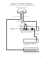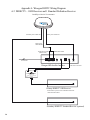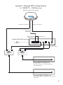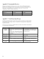
1
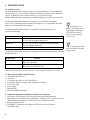
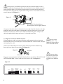
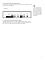
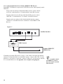
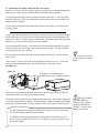
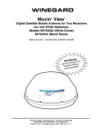
WINEGARD® Satellite Interface Installation/Operation Manual Model WB-2700/WB-2000 Made in the U.S.A. U.S. Patent Pending Interface Satellite T SELEC r o v i d eL r P e c BEL Servi POWER *D T V ENTER DISH Satellite Interface ROL ONT TO C H /DIS E FAC TER TO IN D Converter (DIRECTV® ONLY) T ER VER CON WA ) HD -1100 TON, IO 0 1 7 (1 B ING 7 044 TV EL W URL 241 IREC MOD NY B PA COM RD IVER EGA ECE WIN OR T Mad e in USA Converter required for DIRECTV HDprogramming only. Sold separately. Winegard Company • 3000 Kirkwood St. • Burlington, IA 52601-2000 800/288-8094 • FAX 319/754-0787 • www.winegard.com Printed in U.S.A. © Winegard Company 2007 2452114 Rev. 1/10 Congratulations! You have selected the Winegard Satellite Interface, your source for High Definition Satellite Programming. The Satellite Interface Box enhances your RoadTrip™ or Movin’ View® Satellite Systems, allowing access to more satellites and more HD programming. *The Satellite Interface Box is designed for use with DISH Network, DIRECTV and Bell ExpressVu satellite television providers. This manual provides important information on the installation and operation of your Satellite Interface Box. Please take time to read this manual before installing or operating your antenna. Icons appearing in the manual are used for important information and helpful tips. Alert indicates important information regarding product use, product specifications or procedures. Important tip offers helpful suggestions or refers you to a related topic in the manual. For Winegard Warranty Information: Att: Technical Services Winegard Company 3000 Kirkwood St. Burlington, IA 52601 800-788-4417 Fax: 319-754-0715 Disclaimer Although every effort has been made to insure the information in this manual is correct and complete, no company shall be held liable for any errors or omissions in this manual. All information contained in this manual is subject to change without notice. No warranty of any kind is made with regard to the information included in this manual. The Satellite Interface is designed specifically for use with motorized recreational vehicles and information contained herein is provided for that purpose only. Trademarks *Winegard, Movin’ View and RoadTrip are trademarks of Winegard Company. DISH Network is a registered trademark of EchoStar Satellite L.L.C. DIRECTV is a registered trademark of DIRECTV, Inc., a unit of Hughes Electronics Corp. ExpressVu is a registered trademark of Bell Canada, Inc. All trademarks contained in this manual are property of their respective owners. Reference made to products or services provided by companies, other than Winegard Company, does not represent any endorsement of those products or services. 1 Table of Contents 1. Introduction...................................................................................................................................4 1.1 System Overview................................................................................................................4 1.2 Parts Provided With HD System.........................................................................................4 1.3 Additional Equipment and Materials Required for Operation............................................4 1.4 Satellite Interface Components............................................................................................5 1.5 Accessing the Main Menu...................................................................................................5 2. Safety..............................................................................................................................................6 2.1 Installation Safety................................................................................................................6 3. Installation.....................................................................................................................................6 3.1 Pre-Installation....................................................................................................................6 3.2 Route Cables........................................................................................................................7 3.3 Plug Power Cable into Satellite Interface............................................................................8 3.4 Connect Satellite Antenna to Satellite Interface..................................................................9 3.5 Connect Satellite Interface to Primary HD Receiver..........................................................9 3.5.1 Connect Satellite Interface to Primary DIRECTV HD Receiver...........................10 3.5.2 Connect Satellite Interface to Primary DISH Network or ExpressVu HD Receiver... 11 3.6 Connect Satellite Interface to 110VAC Power....................................................................11 3.7 Install Software Update With Clone Box............................................................................12 3.8 Connect Data Cable to Electronics Board and Replace Dome............................................13 4. DIRECTV Operation....................................................................................................................14 4.1 DIRECTV Overview...........................................................................................................14 4.2 DIRECTV First Time Setup................................................................................................14 4.3 Watching DIRECTV Programming.....................................................................................15 5. DISH Network Operation............................................................................................................17 5.1 DISH Network Overview....................................................................................................17 5.2 DISH Network First Time Setup.........................................................................................17 5.3 Watching DISH Network Programming..............................................................................20 5.4 Satellite 129°W Notice........................................................................................................20 6. Bell ExpressVu Operation............................................................................................................21 6.1 Bell ExpressVu Overview...................................................................................................21 6.2 Bell ExpressVu First Time Setup........................................................................................21 6.3 Watching Bell ExpressVu Programming.............................................................................23 7. Satellite Interface Menu...............................................................................................................24 7.1 Main Menu..........................................................................................................................24 7.2 Satellite Setup Menu...........................................................................................................24 7.3 Sleep Menu..........................................................................................................................27 7.4 Diagnostics Menu...............................................................................................................29 7.5 Configuration Menu............................................................................................................30 2 8. Troubleshooting.............................................................................................................................31 8.1 LCD Error Messages...........................................................................................................31 8.2 Solutions to Common Operating Issues..............................................................................32 Appendices..........................................................................................................................................33 A. Wiring Diagrams...................................................................................................................33 B. Recommended Receivers......................................................................................................36 C. Normal Operating Messages.................................................................................................36 3 1. INTRODUCTION 1.1 System Overview The Winegard HD Satellite Interface allows your Winegard Movin’ View and RoadTrip satellite systems to receive additional KU-band satellites not available with a stand-alone system. In addition to more available satellites, you will be able to enjoy additional High Definition programming available through your satellite service provider. The Winegard HD Satellite Interface is designed for use with either a Winegard Movin’ View or RoadTrip satellite antenna (sold separately). It is compatible with both stationary and in-motion satellite antennas. The Winegard HD Satellite Interface is compatible with the following service providers and satellites: Service Provider Available Satellites DISH Network 119°W, 110°W, 129°W (Automatic and Manual Mode) 61.5°W, 148°W (Manual Mode only) DIRECTV 101°W, 110°W, 119°W (Automatic and Manual Mode) 72.5°W (Manual Mode only) Bell ExpressVu 82°W, 91.5°W (Automatic and Manual Mode) The Winegard HD Satellite Interface is compatible with the following Winegard Automatic Satellite Systems: Product Line Movin’ View RoadTrip Model # MV-3500, MV3500A, MV3535A, MV3500T, MV3535T, WI3535T, MV-0500* RT1200S, RT1235S, RT1200T, RT1235T, RTS-12W, RTS-12B, RTT-12W, RTT-12B *MV-0500 must be upgraded to MV3500A electronics. Contact Winegard Customer Service for details. 1.2 Parts Provided With Satellite Interface 1. HD Satellite Interface Box 2. Clone Box 3. 25’ modular data cable, for use with clone box 4. 30’ modular data/power cable bundle with Heyco Connector 5. 2’ mini coax cable 6. Power Supply 7. Hardware Bag 8. Installation/Operation Manual 1.3 Additional Equipment and Materials Required for Operation 1. Television or Video Monitor, HD Television required for HD programming. 2. Satellite Receiver with authorized programming. An HD receiver is required to receive High Definition programming. Contact your service provider for details. 3. Approved sealant for roof. 4. For DIRECTV subscribers, the Winegard 110°W HD Converter is required (model WB-1100). 4 In order to receive DIRECTV Satellite 110°W programming, a Winegard 110°W HD Converter is required, sold separately (model WB-1100). Some satellites listed are not available in all parts of the country. 1.4 Satellite Interface Components HDTV Satellite Interface User interface for the HD Satellite Interface. Using this panel, the user can select the satellite service provider, choose the toggling pair for DIRECTV, control satellite antenna in manual mode and many more features. Interface also provides +12VDC power to satellite antenna. Satellite Interface POWER SELECT ENTER Select Button Changes selection in interface menu Power Button Switches the Interface Box and Satellite Dish ON and OFF Enter Button Confirms selection in interface menu LCD Display Shows current status of satellite system DIRECTV 110°W HD Converter Required for DIRECTV only. Satellite 110°W provides most of the High Definition content. When satellite 110°W is selected, the HD Converter converts the signal to a frequency that can be read by your DIRECTV High Definition receiver. TO INTERFACE/DISH TO CONTROL DIRECTV® (110°) HD CONVERTER MODEL WB-1100 WINEGARD COMPANY • BURLINGTON, IOWA Made in USA TO RECEIVER 1.5 Accessing the Main Menu You can access the Satellite Interface Main Menu at any time using the following steps. [BUTTON] denotes a button to be pushed on the Satellite Interface front panel, and words in Bold represents options on the LCD screen. The *Asterisk on screen denotes the current selection. 1. Press and Hold [ENTER] button for 2 seconds. 2. Press [SELECT] to choose Yes. 3. Press [ENTER] to confirm selection. You will now be in the Main Menu. 5 2. SAFETY 2.1 Installation Safety: Winegard highly recommends the Winegard HD Satellite Interface be installed by a professional installer, as RV rooftop work may be required, as well as some electrical wiring. Do not install the roof top portion of this system in the rain. Before drilling any holes for installation, make sure there are no obstructions, such as wiring, etc. To protect against water damage, seal any roof top holes with approved sealant. Winegard is not liable for damage, expenses, or injury caused by improper installation. Read the entire manual before attempting to install the system. Follow the instructions carefully. Use all appropriate safety equipment. 3. INSTALLATION 3.1 Pre-Installation Installation Overview (order may change depending on installation) Gather tools and equipment needed for installation. Route new data/power cable, if necessary Install HD Satellite Interface and necessary components Connect Satellite Interface to antenna and receiver Update satellite antenna software, if necessary Plan your entire installation before you start. Determine the location of all of your equipment and make sure cable and wires are long enough to reach their termination points. Tools and Material Required for Installation 1. Drill 2. Phillips #2 Screwdriver or drill bit 3. 5/16” nut driver bit 4. RG-6 coax stripper and crimping tool 5. 7/16” open-ended wrench 6. Sealant (check with your RV manufacturer for proper type) 7. Small flat head screwdriver Select a Location to Install the Satellite Interface For best results, the Winegard Satellite Interface should be installed near the primary receiver in your RV. Be sure an AC power source is available. This manual assumes that a Winegard Satellite System is already fully installed on the RV roof top. If a system has not yet been installed, please refer to the installation manual included with the satellite system for installation instructions. Use the power/data cable included with this kit for satellite antenna installation. 6 If you are installing a new Satellite Antenna with the HD Satellite System, use the cables supplied with this kit for antenna installation. If you are installing the HD Satellite Interface as an add-on to a previously installed Winegard Satellite Antenna, you should install the software update to your satellite antenna first, then proceed with cable and HD Satellite Interface installation. Refer to 3.7 Install Software Update with Clone Box for instructions. 3.2 Route Cables (If Necessary) If your Winegard Satellite System on your roof came installed with the power/data cable, or if your coach was pre-wired for a Winegard Satellite System and HD Interface, you may proceed to the next step. If your system was wired using only the red/black power wire, you must route the new 30’ power/data cable included. If you are replacing the current power wire, remove the sealant and 8 screws from the roof top cable entry plate using the drill and 5/16” nut driver bit and discard. If not already done, remove the dome from the antenna by removing the eight dome screws with a Phillips head screwdriver. Do not lose dome screws! Be sure to verify your previously installed antenna’s wiring. You may be able to save installation time if it already includes the data cable. Trace the current power wire to the Heyco Connector going into base. Remove the large nut, Heyco Connector, and small nut inside base using the 3/4” wrench or crescent wrench and discard. See Figure 3.1. Figure 3.1 Large Nut Small Nut Heyco Connector Locate the green connector that connects the power wire to the electronics board. Using a small flat head screwdriver, unscrew the 2 side screws and disconnect from board. Unscrew top two screws and remove connector from cable. Do not lose green connector! Cut wire ties and pull power cable out of dome. Locate end of new power/data cable with LONGER exposed data cable. Route this end of the power/data cable through power wire hole. With top screws facing up, insert power wire into saved green connector and screw down top screws to secure. See Figure 3.2. Figure 3.2 One end of the power/ data cable has a longer data cable. Use the longer end inside the dome and the short end inside the RV. Red Wire Black Wire Plug green connector into power connector on electronics board. Screw in 2 side screws Be sure loose cables to fasten. Do not connect data cable yet if software update must be done. Pull slack out inside dome will not interfere of cable from outside base, and push new Heyco connector into base. Pull on Heyco to be with dish LNB. sure it is secure. Fasten cable to base cleats or wire tie holders using wire ties. Route power/data cable through existing roof hole and into Interface/Receiver location. You may want to attach new cable to old power cable using electrical tape to help pull wire through. If not already done from a previous installation, route primary coax into hole to receiver as well. If necessary, route second coax to location. 7 At this point, if your Satellite System does not need a software update, or has already been updated, you may plug the data cable inside dome into the modular connection on the electronics board. Verify that all connections have been made and all cables have been tied to base using cable ties. Replace dome using 8 screws. Be sure dome screws are securely fastened. See Figure 3.3. Figure 3.3 Note: Movin’ View board shown. RoadTrip board will be slightly different. After power/data cable and coax cable(s) have been routed to Satellite Interface, seal underneath cable entry plate with approved sealant and screw down plate using 12 screws with drill and 5/16” nut driver. Seal over screw heads and around entry plate. Clamp excess cable with supplied cable clamps and screws. Seal around screw holes. 3.3 Plug Power Cable into Satellite Interface If the original power cable was removed from the satellite antenna in the previous step, disconnect the power wire from the power switch inside the RV. Discard switch, wall plate, and original power cable. Do not cut the power/data cable. You should coil excess cable inside or behind the cabinet. Connect power/data cable power wires to green connector provided in hardware bag. Screw top screws down to secure cables. See Figure 3.4. Figure 3.4 DC IN DC OUT TO SAT ANTENNA BLK/RED COMM. OUT 1 TO SAT. ANTENNA Red Wire Black Wire HD CTRL 2 HD CTRL 1 FACTORY USE ONLY SAT. RECEIVER OUT SAT. ANTENNA IN Plug green connector into back of Satellite Interface Box in port labeled “DC OUT TO SAT ANTENNA BLK/RED.” Screw in side screws to secure to box. See Figure 3.5. Figure 3.5 DC IN 8 DC OUT TO SAT ANTENNA BLK/RED COMM. OUT 1 TO SAT. ANTENNA HD CTRL 2 HD CTRL 1 FACTORY USE ONLY SAT. RECEIVER OUT SAT. ANTENNA IN You may replace your old wall plate with a standard size blank plate available at any hardware store. 3.4 Connect Satellite Antenna to Satellite Interface Locate the primary coax cable from rooftop antenna. Connect it to “Sat Antenna In” on the Satellite Interface. See Figure 3.6. DC IN DC OUT TO SAT ANTENNA BLK/RED COMM. OUT 1 TO SAT. ANTENNA HD CTRL 2 HD CTRL 1 FACTORY USE ONLY SAT. RECEIVER OUT SAT. ANTENNA IN Figure 3.6 DC IN DC OUT TO SAT ANTENNA BLK/RED COMM. OUT 1 TO SAT. ANTENNA HD CTRL 2 HD CTRL 1 FACTORY USE ONLY SAT. RECEIVER OUT SAT. ANTENNA IN The primary coax cable is connected to the electronics board inside the dome. In most antennas, the secondary coax must be connected to the secondary coax port inside the dome. See the manual for more information. 3.5 Connect Satellite Interface to Primary HD Receiver Depending on your satellite service provider, you must connect the Satellite Interface to your primary HD receiver in 1 of 2 ways. The DIRECTV installation begins on the next page. See page 11 for DISH Network and Bell ExpressVu installation. 9 3.5.1 Connect Satellite Interface to Primary DIRECTV HD Receiver Each DIRECTV HD Receiver requires the 110°W HD Converter. (Sold separately, model WB-1100). Using a mini coax cable provided with the HD Converter, connect “Sat Receiver Out” on the Interface to “To Interface/Dish” on the HD Converter. Using the other mini coax cable provided with the HD converter, connect “HD CTRL 1” on the Interface to “To Control” on the HD Converter. Using the mini coax cable provided with the Satellite Interface, connect “To Receiver” on the HD converter to “Satellite In” on the DIRECTV HD Receiver. Figure 3.7 Satellite Interface DC IN TO INTERFACE/DISH DC OUT TO SAT ANTENNA BLK/RED COMM. OUT 1 TO SAT. ANTENNA HD CTRL 2 HD CTRL 1 FACTORY USE ONLY SAT. RECEIVER OUT SAT. ANTENNA IN TO CONTROL DIRECTV® (110°) HD CONVERTER HD Converter MODEL WB-1100 WINEGARD COMPANY • BURLINGTON, IOWA Made in USA TO RECEIVER SATELLITE IN Primary DIRECTV HD Receiver If installing a secondary HD receiver, repeat 3.5.1, but connect coax cable from Satellite Antenna to “To Interface/Dish” on second HD Converter. Connect “HD CTRL 2” on the Interface to “To Control” on Converter. Connect “To Receiver” on Converter to “Satellite In” on second HD Receiver. See Appendix A for a complete wiring diagram. 10 A secondary standard DIRECTV receiver does not require a second HD Converter. 3.5.2 Connect the Satellite Interface to Primary DISH Network or ExpressVu HD Receiver Using the mini coax cable provided with the Satellite Interface, connect “Sat Receiver Out” on the Satellite Interface to “Satellite In” on the DISH Network or ExpressVu HD receiver. See Figure 3.8. See Appendix A for a complete wiring diagram. Figure 3.8 DC IN DC OUT TO SAT ANTENNA BLK/RED Satellite Interface COMM. OUT 1 TO SAT. ANTENNA HD CTRL 2 HD CTRL 1 FACTORY USE ONLY SAT. RECEIVER OUT SAT. ANTENNA IN SATELLITE IN Primary DISH Network or ExpressVu HD Receiver If connecting a secondary HD or standard definition receiver, route secondary coax cable from satellite antenna to “Satellite In” on receiver. 3.6 Connect the Satellite Interface to 110VAC Power Plug AC Power Adapter into “DC IN” port on back of Satellite Interface. Plug the other end into a 110V AC outlet. Ensure that all cable connections have been made correctly before powering unit on for the first time. 11 3.7 Install Software Update with Clone Box (if necessary) It may be necessary to install a software update to your previously installed Winegard Satellite System to ensure proper communication with the HD Satellite Interface. If your Winegard Satellite system was installed without a data cable, ie. only coax cables and a black/red power cable were installed, it will most likely be necessary to update the satellite system’s software. If your system was installed with a data cable included, most likely you will not need to install the update. If you are installing an HD Satellite System as an add on to previously installed Winegard Satellite System, you will continue to power the satellite antenna on/off through the wall plate power switch. If you have already connected the power/data cable to the HD Satellite Interface, you will power dish with Interface Power Button. Power on the Satellite Antenna. If you are connected to the Satellite Interface, the status screen will show an error message. You can disregard this message. The dish will begin moving and may lock onto a satellite. If not already done, remove the dome by removing the 8 dome screws. Do not lose the dome screws! Connect the 25’ clone box data cable to the modular port on the clone box. Connect the other end to the modular data port on the satellite antenna’s electronics board. See Figure 3.9 Figure 3.9 It is okay for the dish to move during the software update. Note: Movin’ View board shown. RoadTrip board will be slightly different. The clone box will automatically begin the software upload. A green then red light will immediately flash, followed by the green light flashing. DO NOT POWER During the software upload, the green light will flash repeatedly. The software update proc- OFF THE DISH OR ess will take approximately 2 minutes. When the software update is complete, the flashing UNPLUG ANY CABLE green light will become solid. You may unplug the clone box from the electronics board. DURING SOFTWARE UPDATE!. Doing so may Potential Error Messages damage your system. If a solid red light comes on after you plug in the system, your system is incompatible with the Winegard Satellite Antenna (Dish). If a flashing red light appears during the software upload, an upload error has occurred. Turn your satellite dish off, wait 15 seconds, then power it on again to retry the software upload. 12 After the software has been loaded, you are ready to proceed to the next step. If you are installing the HD Satellite Interface as an add-on and have not yet installed the data cable and interface, return to section 3.2 Route Cables. If you have already installed the Satellite Interface and data cable, you must power cycle the interface after the software update has been made for proper communication with satellite antenna. 3.8 Connect Data Cable to Electronics Board and Replace Dome If you have already installed power/data cable, you are ready to finish the rooftop installation. After disconnecting the clone box data cable, plug in the modular data cable from the power/data cable into the modular connection on the electronics board. See Figure 3.10. Figure 3.10 Note: Movin’ View board shown. RoadTrip board will be slightly different. Verify that all connections have been made inside dome and that all cables have been tied down to base using cable ties. Replace dome using 8 dome screws. 13 4. DIRECTV Operation 4.1 DIRECTV Overview When connected to a Winegard automatic satellite antenna, the Winegard HD satellite Interface is capable of receiving the following satellites: • • • 101°W - Majority of standard programming 119°W - Standard programming and some HD programming 110°W - Only HD programming. Requires converter In automatic mode, the satellite antenna will automatically toggle between pairs of user defined satellites. The toggle feature will work while stationary for all models and in-motion for in-motion model satellite antennas. The pair can be selected from the main display of the Satellite Interface. The available satellite pairs are: 101°W and 110°W 101°W and 119°W You may also operate the satellite antenna in Manual Mode. More information on Manual Mode is available in Section 7.2. 4.2 DIRECTV First Time Setup Configure Satellite Interface box for DIRECTV programming Press [Power] to power on the Satellite Interface and Satellite Antenna. The antenna will begin it’s search for its pre-set satellite. Access the Main Menu. Press and hold the [ENTER] button for 2 seconds. Press [SELECT] to choose Yes. Satellite Interface POWER Enter User Menu? *Yes No SELECT ENTER Press [ENTER] to confirm selection. You are now in the Main Menu. Press [ENTER] to confirm Satellite Setup. Satellite Interface POWER Satellite Setup* Enter Sleep SELECT ENTER Press [ENTER] to confirm Sat Provider. From Service Provider menu press [ENTER] to confirm DTV. Satellite Interface POWER Service Provider *DTV DISH BELL SELECT ENTER Select Yes and press [ENTER] to save setting. The satellite antenna will reset and begin its search routine for satellite 101°W. Your satellite antenna is now set for DIRECTV programming.Each time you power on the Satellite Interface, the satellite antenna will locate DIRECTV satellite programming. 14 Toggle - the dish will automatically switch satellites by changing channels on your remote control. Configure DIRECTV Receiver Antenna Type You must set your DIRECTV receiver to the “Oval Dish, 3 Satellites” Dish Type. As many DIRECTV receivers have been made by different manufacturers, consult your receiver’s owners manual for instructions on changing Dish Type. 4.3 Watching DIRECTV programming Power on the Winegard Satellite Interface. In a few moments, the satellite antenna will begin its search routine. It will verify satellites and lock onto DIRECTV satellite 101°W. If you have an in-motion antenna, the antenna will continue to “track” the satellite for 7 minutes after signal acquisition. After 7 minutes, it will enter sleep mode. You can watch television as normal while the antenna is tracking. For instructions on how to force sleep mode, see Section 7.3. You can view the satellite acquisition status from the LCD status screen as well as the DIRECTV signal strength screen. Choosing the Satellite Pair After the antenna has locked onto DIRECTV programming, the LCD Status Screen on the Satellite Interface will display the alternate satellite menu. At any time, you may choose which satellite will be the alternate toggling satellite with 101°W. See Figure 4.1. Figure 4.1 - Sat 110°W chosen as alternate satellite Satellite Interface POWER DTV 101 Locked alt: 119 *110 SELECT ENTER To change the alternate satellite, press [SELECT] to choose your desired alternate satellite. Press [ENTER] to confirm. If you are watching satellite 101°W programming, changing the alternate satellite will not affect your viewing until you change to a channel on the alternate satellite. If you are watching programming on one of the alternate satellites and switch to the other, your dish will move immediately to the selected alternate satellite. Important DIRECTV Program Guide and Channel Note When you power on the Satellite Interface and DIRECTV receiver, your DIRECTV receiver will download the program guide after signal acquisition. The receiver will download the guide for Satellite 101°W as well as the guide for your alternate satellite chosen at the time of power up. It may take up to 20 minutes to download the guide for the third satellite. If a channel is not available in the programming guide, you will not be able to select it. Please be patient while the guide fully downloads. The Satellite Interface will remember which alternate satellite was selected before it was powered off. As an example, if you frequently watch programming on Satellite 110°W over satellite 119°W, you should select satellite 110°W before you power off the Satellite Interface. The 110°W guide will download immediately after the next signal acquisition. 15 Example of DIRECTV Satellite Switching. For a brief example of DIRECTV satellite switching, read the following example. You have powered on the dish, and you have locked onto satellite 101°W and watch as the guide begins to download. Satellite 110°W is your chosen alternate satellite. Satellite Interface POWER DTV 101 Locked alt: 119 *110 SELECT ENTER After a few moments, the guide for satellites 101°W and 110°W are fully downloaded. You begin watching a standard definition program on satellite 101°W After some time, you decide to switch to a High Definition program on satellite 110°W. You select the channel, and the dish seamlessly toggles to satellite 110°W. After waiting for the 119°W guide to download, you decide to watch another High Definition program on satellite 119°W. On the HD Satellite Interface, press [SELECT] to highlight 119. Press [ENTER] to confirm. Satellite Interface POWER DTV 101 Locked alt: 119 *110 SELECT ENTER Because you were on an alternate satellite already, the dish will immediately move to satellite 119 °W. Change to a channel on that satellite and watch your program. Finally, you decide to watch a standard definition program on satellite 101°W. Select the channel, and the dish will seamlessly toggle to satellite 101°W. If you power off the Satellite Interface at this point, satellite 119°W will be stored as your alternate satellite. The guide for satellite 101°W and 119°W will be downloaded immediately next time you power on the system. Note on Satellite Switching. If you change to a channel and the DIRECTV program banner shows the correct channel but an unexpected program is on, check to see that you have the Satellite Interface set to the correct alternate satellite. 16 5. DISH Network Operation 5.1 DISH Network Overview When connected to a Winegard Automatic Satellite System, the Winegard HD satellite Interface is capable of receiving the following satellites automatically: • • • Satellite 119°W - Majority of standard programming Satellite 110°W - Standard and HD programming Satellite 129°W - HD programming only In Automatic Mode, your Winegard automatic satellite antenna will automatically toggle between the 3 satellites as you change channels on your Dish Network remote control. The toggle feature will work while stationary for all models and in-motion for in-motion model satellite antennas. You may also operate the satellite antenna in Manual Mode. You will be able to access additional available Dish Network satellites, including 61.5°W and 148°W. More information on manual mode is available in Section 7.2. Toggle - the dish will automatically move between satellites by changing channels on your remote control. 5.2 DISH Network First Time Setup Configure Satellite Interface box for DISH Network programming Press [Power] to power on the Satellite Interface and Satellite Antenna. The antenna will begin it’s search for its pre-set satellite. Access the Main Menu. Press and hold the [ENTER] button for 2 seconds. Press [SELECT] to choose Yes. Satellite Interface POWER Enter User Menu? *Yes No SELECT ENTER Press [ENTER] to confirm selection. You are now in the Main Menu. Press [ENTER] to confirm Satellite Setup. Satellite Interface POWER Satellite Setup* Enter Sleep SELECT ENTER Press [ENTER] to confirm Sat Provider. From Service Provider menu press [SELECT] to select DISH. Satellite Interface POWER Service Provider *DTV DISH BELL SELECT ENTER Press [ENTER] to confirm. 17 You must now choose if you subscribe to DISH 500 or DISH 1000 programming. Call DISH Network customer service if you are unsure of your programming option. If you subscribe to all High Definition programming, you should choose the DISH 1000 option. Press [SELECT] to select your DISH Network Programming Type. Satellite Interface POWER DISH 1000* DISH 500 SELECT ENTER Press [ENTER] to confirm. Select Yes and press [ENTER] to save the setting. A confirmation message will appear. The satellite antenna will reset and begin its search routine for satellite 119. Your satellite antenna is now set for DISH Network programming. Each time you power on the Satellite Interface, the satellite antenna will locate DISH Network programming. Configure DISH Network Receiver In order to use the satellite antenna in automatic mode, the DISH Network Receiver must be configured with the proper switch installed. The DISH Network switch tells the receiver which satellite to look at, depending which channel the receiver is tuned to. The DISH Network switch is a receiver setting, not a physical part. If you use your receiver in your RV only, you should only have to run the “Check Switch” test during the initial installation. If you move your Receiver between your RV and your home, you must run the “Check Switch” test each time you move your receiver. For example, if your receiver is in your home and you move it to your RV, you must run the check switch test once your RV’s satellite system is on signal. If you move your receiver from your RV to your home, you should run the check switch after you have connected your receiver to your home antenna. Refer to your receiver manual for more information. Install the Satellite Switch For most DISH Network receivers, the following commands will help you navigate to the correct menu locations. If you need help reaching the following menus, refer to your receiver’s manual. Power on your satellite receiver and press [POWER] on the Satellite Interface. The antenna will begin its search routine and lock on to and come to rest on satellite 119°W after some satellite verification. If you have an in-motion system, the antenna will enter “tracking” mode for 7 minutes after locking on to the signal. After 7 minutes, the dish will enter sleep mode. For best results, wait until the unit is in sleep mode to run the check switch test. 18 If you install a second receiver, you should connect the secondary receiver to the primary coax and run the switch test. After test is complete, connect the receiver to a secondary coax at receiver’s permanent location. After unit enters Sleep Mode, you now have 6 minutes to run the check switch test. Press the “Menu” button on the DISH Network remote control. Select “System Setup” option “6”. Select “Installation”, option “1”. Select “Point Dish/Signal” option “1”. If you do not see signal on your meter, be sure satellite 119 is selected and try a different transponder. All transponders may not be active. See Figure 5.1. Figure 5.1 - Actual Screen may vary Point Dish Wed March 21 To calculate DISH500 Peak Angles Enter your ZIP Code and select satellite 110 or 119. Zip Code 71601 Dish System Transponder Satellite 500 11 Check Switch Done 119 Help Azimuth: 214 0 25 Elevation: 43 50 Locked - EchoStar 119 West Skew:120 75 100 Signal Strength 125 96 Select “Check Switch” from the Point Dish Screen. Be sure that any options, such as “Alternate” or “Superdish” are unchecked. Select “Test.” The receiver will test the satellite antenna to verify which switch should be installed. After the test is completed, the check switch screen will report the result. See Figure 5.2. Figure 5.2 - Actual Screen may vary Satellite Input 2 3 Port: 1 Satellite: 119 110 129 Trans: OK OK OK Device: Status: Reception Verified Switch: SW64 Alternate SuperDISH Test Satellite Input 2 Port: 1 Satellite: 119 110 Trans: OK OK Device: Status: Reception Verified Switch: SW64 Done Help DISH 1000 Programming DISH 500 DISH 1000 Alternate SuperDISH Test Done Help DISH 500 Switch Installed SW42 SW64 Available Satellites 119°W, 110°W 119°W, 110°W, 129°W 19 5.3 Watching DISH Network programming Power on the Winegard Satellite Interface. In a few moments, the satellite antenna will begin its search routine. It will verify satellites and lock onto DISH Network satellite 119°W. If you have an in-motion antenna, the antenna will continue to “track” the satellite for 7 minutes after signal acquisition. After 7 minutes, it will enter sleep mode. You can watch television as normal while the antenna is tracking. For instructions on how to force sleep mode, see Section 7.3. 5.4 Satellite 129°W Notice DISH Network Satellite 129°W may not be available in all areas of the country, even under ideal conditions. Due to weak signal strength and its location over the west coast, this is especially true in the eastern and extreme southern parts of the country. If satellite 129°W is not available in your area, you will not be able to run a check switch test in “DISH 1000” mode. If you wish to operate in automatic mode, use “DISH 500” mode and run the check switch test. If you are unable to acquire adequate signal from Satellite 129°W in your area, an alternative is to use Satellite 61.5°W for High Definition programming. In addition to broadcasting some international programming, Satellite 61.5°W also mirrors all High Definition programming from Satellite 129°W. Satellite 61.5°W may be easier to acquire in the eastern part of the country than Satellite 129°W. In order to watch programming from Satellite 61.5°W, you must operate the satellite antenna in Manual Mode. Rather than toggling automatically between satellites, you must select your satellite through the Satellite Interface. Before you can operate in manual mode, you must first clear the installed switch out of the receiver. Power off the Satellite Interface. Disconnect the coax cable to “Satellite In” on the back of the receiver. You must not be on signal to clear out the switch. Instead of unplugging the coax cable, you may also power the dish on, wait until it begins moving, then power the dish off. Check the “Point Dish” screen to verify loss of signal. Press the “Menu” button on the DISH Network remote control. Select “System Setup” option “6”. Select “Installation”, option “1”. Select “Point Dish/Signal” option “1”. Verify that you do not receive signal. Select “Check Switch” from the Point Dish Screen. Be sure that any options, such as “Alternate” or “Superdish” are unchecked. Select “Test.” The receiver will test the satellite antenna to verify which switch should be installed. After the test is completed, the check switch screen will report the result. See Figure 5.3. If the receiver reports “Installed Switch Unknown” or “None”, you may now operate your antenna in Manual Mode. See 7.2 Manual Mode, for operating instructions. Figure 5.3 - Actual Screen may vary Port: Satellite: Trans: Device: Status: Switch: Satellite Input Reception Verified None Alternate SuperDISH Test 20 1 X X Done Help 6. Bell ExpressVu Operation 6.1 Bell ExpressVu Overview When connected to a Winegard Automatic Satellite System, the Winegard HD satellite Interface is capable of receiving the following satellites automatically: • • Satellite 82°W Satellite 91°W In Automatic Mode, your Winegard automatic satellite antenna will automatically toggle between the 2 satellites as you change channels on your ExpressVu remote control. The toggle feature will work while stationary for all models and in-motion for in-motion model satellite antennas. You may also operate the satellite antenna in Manual Mode. More information on manual mode is available in Section 7.2. Toggle - the dish will automatically switch satellites by changing channels on your remote control. 6.2 Bell ExpressVu First Time Setup Configure Satellite Interface box for Bell ExpressVu programming. Press [Power] to power on the Satellite Interface and Satellite Antenna. The antenna will begin it’s search for its pre-set satellite. Access the Main Menu. Press and hold the [ENTER] button for 2 seconds. Press [SELECT] to choose Yes. Satellite Interface POWER Enter User Menu? *Yes No SELECT ENTER Press [ENTER] to confirm selection. You are now in the Main Menu. Press [ENTER] to confirm Satellite Setup. Satellite Interface POWER Satellite Setup* Sleep Menu SELECT ENTER Press [ENTER] to confirm Sat Provider. From Service Provider menu press [SELECT] 2 times to select Bell. Satellite Interface POWER Service Provider *DTV DISH BELL SELECT ENTER Press [ENTER] to confirm. Select Yes and press [ENTER] to Save. 21 A confirmation message will appear. The satellite antenna will reset and begin its search routine for satellite 91°W . Your satellite antenna is now set for Bell ExpressVu programming. Each time your power on the Satellite Interface, the satellite antenna will locate Bell ExpressVu programming. Configure Bell ExpressVu Receiver In order to use the satellite antenna in automatic mode, the Bell ExpressVu must be configured with the proper switch installed. The Bell ExpressVu switch tells the receiver which satellite to look at, depending which channel the receiver is tuned to. The Bell ExpressVu switch is a receiver setting, not a physical part. If you use your receiver in your RV only, you should only have to run the “Check Switch” test during the initial installation. If you move your Receiver between your RV and your home, you must run the “Check Switch” test each time you move your receiver. For example, if your receiver is in your home and you move it to your RV, you must run the check switch test once your RV’s satellite system is on signal. If you move your receiver from your RV to your home, you should run the check switch after you have connected your receiver to your home antenna. Refer to your receiver manual for more information. Install the Satellite Switch For most Bell ExpressVu receivers, the following commands will help you navigate to the correct menu locations. If you need help reaching the following menus, refer to your receiver’s manual. Power on your satellite receiver and press [POWER] on the Satellite Interface. The antenna will begin its search routine and lock on to and come to rest on satellite 91°W after some satellite verification. If you have an in-motion system, the antenna will enter “tracking” mode for 7 minutes after locking on to the signal. After 7 minutes, the dish will enter sleep mode. For best results, wait until the unit is in sleep mode to run the check switch test. You now have 6 minutes to run the check switch test. Press the “Menu” button on the Bell ExpressVu remote control. Select “System Setup” option “6”. Select “Installation”, option “1”. 22 If you install a second receiver, you should connect the secondary receiver to the primary coax and run the switch test. After test is complete, connect the receiver to a secondary coax at receiver’s permanent location. Select “Point Dish/Signal” option “1”. If you do not see signal on your meter, be sure satellite 91 is selected and try a different transponder. All transponders may not be active. See Figure 6.1. Figure 6.1 - Actual Screen may vary POINT DISH/ SIGNAL STRENGTH Satellite 0 61.5 West 105 West 110 West 119 West 121 West 129 West 148 West 25 PEAK ANGLES Transponder 11 CHECK SWITCH CANCEL HELP 50 Locked - EchoStar 119 West 75 100 125 signal strength 75 Select “Check Switch” from the Point Dish Screen. Be sure that any options, such as “Alternate” are unchecked. Select “Test.” The receiver will test the satellite antenna to verify which switch should be installed. After the test is completed, the check switch screen will report the result. The switch type installed should be “SW42”. If this switch is not installed correctly, please run the check switch test again. 6.3 Watching Bell ExpressVu programming Power on the Winegard Satellite Interface. In a few moments, the satellite antenna will begin its search routine. It will verify satellites and lock onto Bell ExpressVu satellite 91°W. If you have an in-motion antenna, the antenna will continue to “track” the satellite for 7 minutes after signal acquisition. After 7 minutes, it will enter sleep mode. You can watch television as normal while the antenna is tracking. For instructions on how to force sleep mode, see Section 7.3. 23 7. Satellite Interface Menu 7.1 Main Menu After the Satellite Interface has been powered on and the antenna has acquired the satellite signal, the status screen will the display the current satellite. Follow the steps below to access the main menu at any time. [BUTTON] denotes a button to be pushed on the Satellite Interface front panel, and words in Bold represents options on the LCD screen. The *Asterisk onscreen denotes the current selection. Press and hold the [ENTER] button for 2 seconds. Press [SELECT] to select Yes. Satellite Interface POWER Enter User Menu? *Yes No SELECT ENTER Press [ENTER] to confirm selection. You will now be in the Main Menu. Main Menu options flow in the following order: Satellite Setup → Sleep Menu → Diagnostics → Configuration → Exit To Exit the Main Menu at any time, press [SELECT] until Exit is selected. Press [ENTER] to confirm. You will return to the status screen. 7.2 Satellite Setup Menu Automatic Mode From the Satellite Setup menu, you may choose your satellite service provider to operate in Automatic Mode, or you may choose to control the antenna in Manual Mode. For more information on Automatic Mode, please see the Operations Section for your Satellite Service Provider. Satellite Setup Menu options flow in the following order: Sat Provider→ Manual Mode → Factory Default → Exit Choose a Satellite Service Provider for Automatic Mode. From the Main Menu, press [ENTER] to confirm Satellite Setup. Satellite Interface POWER Satellite Setup* Sleep Menu Press [ENTER] to confirm Sat Provider. 24 SELECT ENTER From the Service Provider menu press [SELECT] until your Satellite Service Provider is selected. DTV → DIRECTV DISH → DISH Network BELL → Bell ExpressVu Satellite Interface POWER Service Provider *DTV DISH BELL SELECT ENTER Press [ENTER] to confirm. If DISH Network is chosen, you must then select DISH 500 or DISH 1000. If you are unsure, check with your satellite service provider. If you subscribe to all DISH Network High Definition programming, select DISH 1000. Manual Mode Manual Mode should be used to access additional satellites that are not available in Automatic Mode. Rather than acquiring the primary satellite for your service provider and automatically toggling between alternate satellites, the user must choose the satellite that the antenna will point to. Automatic toggle is not available in Manual mode. Each time a new satellite is chosen in Manual Mode, the Antenna and Satellite Interface will reset, and the satellite signal will be reacquired. See the chart below for a list of satellites available in manual mode: Service Provider DISH Network DIRECTV* Bell ExpressVu Available Satellites 61.5°W, 110°W, 119°W, 129°W, 148°W 72.5, °W, 101°W, 119°W 82°W, 91.5°W * DIRECTV Satellite 110°W is not available in Manual Mode Note for DISH Network and Bell ExpressVu Manual Mode operation. To operate in Manual Mode for DISH Network or Bell ExpressVu, you must first remove the installed switch from the receiver before operating. See p. 20 for instructions on removing the switch. After the switch has been removed, you may manually select a satellite. The antenna will reboot and will acquire satellite reception. The Guide for the current satellite only will download. If a new satellite is chosen in Manual Mode, the antenna will acquire the satellite. Depending on the Satellite Receiver used and its software, you may need to reset your receiver to properly acquire satellite reception and download the new guide. 25 To reset the Satellite Receiver, press and hold the Power button on the Receiver (not on the remote control). The receiver will reset, and after a few moments will automatically restart. It may take up to 5 minutes for some receivers to restart. After the receiver reboots, the new Guide will download, and the programming on the new satellite will be available. You must repeat this process each time you manually change satellites for DISH Network or Bell ExpressVu. Returning to Automatic Mode The antenna will remain in Manual Mode until a Service Provider is chosen to put the antenna back into Automatic Mode. See the operating section for your service provider for instructions on choosing your service provider. To Operate in Manual Mode From the Main Menu, press [ENTER] to confirm Satellite Setup. Satellite Interface POWER Satellite Setup* Sleep Menu SELECT ENTER Press [SELECT] to select Manual Mode. Satellite Interface POWER Manual Mode* Factory Default SELECT ENTER Press [ENTER] to confirm. Press [SELECT] to cycle through the available satellites. Satellite Interface POWER Sat: 61.5 72.5 SELECT ENTER When you have selected your desired satellite, press [ENTER]. A Confirmation screen will appear, and you will be prompted to Save Changes. Press [SELECT] to select YES. Press [ENTER] to confirm. The Satellite Interface will reset, and the satellite antenna will begin its search routine for the selected satellite. After acquisition, you will be able to watch television on the selected satellite. 26 Factory Default If you determine that your satellite antenna is not functioning as expected, you may want to return your system to factory default and run the satellite setup again. From the Main Menu, press [ENTER] to confirm Satellite Setup. Press [SELECT] 2 times to select Factory Default. Satellite Interface POWER Factory Default* Exit SELECT ENTER Press [ENTER] to confirm. A confirmation will appear. Press [SELECT] to select Yes, then press [ENTER] to confirm. A confirmation message will appear, and the Satellite Interface will reset. You should now repeat satellite setup. 7.3 Sleep Menu The Sleep Menu is applicable for in-motion systems only. The Sleep Menu will have no effect on stationary only systems. An in-motion satellite system has two modes, Tracking Mode and Sleep Mode. In Tracking Mode, the satellite antenna is actively following the satellite. If the antenna senses RV movement, it will move along with the RV. The antenna will automatically enter Sleep Mode if it does not sense movement in the RV for 7 minutes. In sleep mode, the antenna remains motionless on the satellite signal. Sleep Menu options flow in the following order: Enter Sleep → Exit Sleep Mode → Set Sleep Time → Default Sleep → Exit From the Main Menu, press [SELECT] to select Sleep Menu. Satellite Interface POWER Sleep Menu* Diagnostics SELECT ENTER Press [ENTER] to confirm. Enter Sleep You may force the antenna into Sleep Mode at any time while the system is in Tracking Mode. From the Sleep Menu, press [ENTER] to confirm Enter Sleep. Satellite Interface POWER Sleep Menu* Exit Sleep Mode SELECT ENTER A confirmation message will appear. The antenna will immediately exit Tracking Mode and enter Sleep Mode. 27 Exit Sleep Mode You may force the antenna into Tracking Mode at any time while the system is in Sleep Mode. From the Sleep Menu, press [SELECT] to select Exit Sleep Mode. Satellite Interface POWER Exit Sleep Mode* Set Sleep Time SELECT ENTER Press [ENTER] to confirm. A confirmation message will appear. The antenna will immediately exit Sleep Mode and enter Tracking Mode. Set Sleep Time While in Tracking Mode, if the antenna does not sense movement for a set amount of time, the antenna will automatically exit Tracking Mode and Enter Sleep Mode. The default timer is set to 7 minutes. From the Sleep Menu, press [SELECT] 2 times to select Set Sleep Time. Satellite Interface POWER Set Sleep Time* Default Sleep SELECT ENTER Press [ENTER] to confirm. You will enter the Set Sleep Timer menu. Sleep Timer Range is from 0000-1999, and is measured in seconds. Note: By setting the Sleep Timer to 0000, the dish will never enter Sleep Mode. The dish will constantly track the satellite whether stationary or in-motion. Press [SELECT] to increase selected digit by 1. Press [ENTER] to confirm digit and move to next digit. Satellite Interface POWER Set Sleep Timer 0420 seconds SELECT ENTER After 4th digit is set, press [ENTER] to confirm new time. You will be prompted to Save Setting. Press [SELECT] to select Yes, then [ENTER] to confirm. A confirmation screen will appear and you will return to the status screen. 28 Winegard does not recommend setting sleep timer to less than 3 minutes. Your dish may unexpectedly enter sleep mode, such as at a traffic light or stop sign. Default Sleep You may return the Satellite Interface to the factory default sleep time of 7 minutes (420 seconds). From the Sleep Menu, press [SELECT] 3 times to select Set Sleep Time. Press [ENTER] to confirm. You will be asked if you are sure. Press [SELECT] to select Yes, then press [ENTER] to confirm. 7.4 Diagnostics Menu The Diagnostics Menu displays software versions installed in the system. In future updates, advanced troubleshooting options will be available for the system. Diagnostics Menu options flow in the following order: IDU SW Version → IDU HW Version → ODU SW Version → ODU HW Version → DSQ SW Version → Exit Menu Option IDU SW Version IDU HW Version ODU SW Version ODU HW Version DSQ SW Version Explanation Satellite Interface Software Version Installed Satellite Interface Hardware Version Satellite Dish Software Version Installed Satellite Dish Hardware Version DiSEQ Software Version Installed To check software versions, follow these steps: From the Main Menu, press [SELECT] 2 times to select Diagnostics. Satellite Interface POWER Diagnostics* Configuration SELECT ENTER Press [ENTER] to confirm. Press [SELECT] to cycle through menu options. Satellite Interface POWER IDU SW Version* IDU HW Version SELECT ENTER Press [ENTER] to confirm. Version information will be displayed, then will automatically return to the Diagnostics Menu. 29 7.5 Configuration Menu The Configuration Menu is only to be used by Winegard Authorized Dealers or under the direction of Winegard personnel. The Configuration Menu is password protected for Winegard use only. 30 8. Troubleshooting 8.1 LCD Error Messages The table below is a list of Satellite Interface error messages that may be displayed on the LCD Status Screen during operation. Before calling for service, please read the solutions section of the table carefully for your specific error message. You may be able to fix some simple problems. Always power cycle your Satellite Interface system by powering the system off then on if you receive an error message. If the error message is not repeated, a slight system error may have occurred. Also power cycle the unit each time a solution is tested. LCD Error Message Cause Solutions SATELLITE SEARCH Stationary search has failed after scanning 1. Be sure there is an unobstructed view of deFAILED all elevation angles sired satellite(s) 2. Check for +12VDC to +18VDC on coax cable on roof connected to receiver 3. Check all coax connections 4. Excessive dome moisture buildup and poor weather may disrupt your satellite reception ELEVATION HOME Elevation Limit Switch was not located Power cycle the Satellite Interface FAILED AZIMUTH HOME Azimuth Limit Switch was not located Power cycle the Satellite Interface FAILED TUNER / DEMOD Cannot communicate with satellite tuner Power cycle the Satellite Interface FAILED GYRO Gyro initiation failed on in-motion system. 1. Unplug gyro cable (USB cable) on Movin’ FAILED View. Check connections 2. Power cycle the Satellite Interface GPS GPS initialization failed at antenna power Power cycle the Satellite Interface FAILED up WAITING TO A valid GPS signal has not been acquired 1. Be sure that GPS antenna is not obstructed ACQUIRE GPS 2. Sometimes after extended travel, GPS may take up to 20 minutes to fully download 3. Be sure that GPS antenna cable is fully seated into connector on electronics board IDU CONFIG Communication between Sat Interface and 1. Restart system antenna has failed 2. Check communication cabling LNB POLARITY Antenna is unable to control the Sat Inter- 1. Check communication cabling DEFAULT FAILED face LNB voltage NO RECEIVER Satellite receiver voltage is not detected at 1. Check that sat receiver “satellite in” coax caVOLTAGE! Sat Interface ble is connected to proper port on sat interface 2. Replace receiver cable LNB SHORT! Satellite receiver voltage is present but no 1. Check coax cable from antenna to sat interLNB voltage is detected face; cable may have been installed incorrectly or damaged during installation lost antenna Communication to the antenna has failed 1. Check data cable to antenna communications 2. Check power cable to antenna 31 8.2 Solutions to Common Operating Issues Symptom Push power button and Interface does not power up Push power button and Interface powers on but antenna does not begin searching Solution Check that Satellite Interface is connected to good AC power source Be sure that the antenna +12VDC power cable is connected to proper port on Satellite Interface Be sure that green power connector has been wired correctly at Interface and inside dome Satellite Interface LCD screen is locked up; pushing but- Hard boot the Satellite Interface by unplugging the Interface tons does not get a response from unit power cable from the power source, wait 10 seconds, then plug it back in. Reboot Satellite Interface The LCD screen says I have locked on to DISH Network Check the installed switch in the receiver. See Section 5.2 satellite 119, but I am not getting television picture and for instructions. the receiver’s signal meter does not show signal If the receiver switch installed is anything other than “SW42”, “SW64”, “Installed Switch Unknown” or “None”, you may have an incompatible switch installed. I cannot access all of my channels for DISH Network or DIRECTV Read Section 5.2 for instructions on removing switch You must wait for the guide for your service provider to fully download If the channel has not loaded into your guide, you will not be able to watch the channel Check that the channel you are trying to receive is available on the satellites available with the Satellite Interface. You may need to operate in Manual Mode to watch some programming Check the signal strength of the current satellite. A satellite may not be available due to weather conditions or location Be sure that your receiver is activated for your programming. Call Customer Service for your programming provider For DIRECTV, the channel banner says that I am watch- Be sure that you have the corrrect alternate satellite chosen ing the channel and show that I want, but the programon the Satellite Interface ming on TV is incorrect For example, you may be watching a show on 119, but the alternate satellite is set for 110 My antenna will not automatically toggle between satel- Be sure that you have chosen your service provider to operate lites in Automatic Mode Automatic toggle is not available in Manual Mode 32 Appendix A Winegard HDTV Wiring Diagram A.1 DISH Network - 1 or 2 HD or Standard Receivers RoadTrip or Movin’ View Antenna Primary Coax Cable Out Secondary Coax Cable Out Data / Power Cable Bundle +12VDC Power Cable (Black / Red) 110 V Power DC IN DC OUT TO SAT ANTENNA BLK/RED Modular Data Cable COMM. OUT 1 TO SAT. ANTENNA HD CTRL 2 HD CTRL 1 FACTORY USE ONLY SAT. RECEIVER OUT SAT. ANTENNA IN Winegard HD Satellite Interface Coax Out to Primary Receiver SATELLITE IN Primary DISH Network HD Receiver Note: Refer to your receiver’s manual for television connection instructions. SATELLITE IN Secondary DISH Network Receiver (optional) Note: May be standard or High Definition Receiver 33 Appendix A Winegard HDTV Wiring Diagram A.2 DIRECTV - 1 HD Receiver and 1 Standard Definition Receiver RoadTrip or Movin’ View Antenna Primary Coax Cable Out Secondary Coax Cable Out Data / Power Cable Bundle 12VDC Power Cable (Black / Red) 110 V Power DC IN Modular Data Cable DC OUT TO SAT ANTENNA BLK/RED COMM. OUT 1 TO SAT. ANTENNA HD CTRL 2 HD CTRL 1 FACTORY USE ONLY Winegard HD Satellite Interface SAT. RECEIVER OUT SAT. ANTENNA IN Coax Out to Converter Coax Out to Control TO INTERFACE/DISH TO CONTROL DIRECTV® (110˚) HD CONVERTER MODEL WB-1100 WINEGARD COMPANY • BURLINGTON, IOWA Made in USA TO RECEIVER coax to receiver SATELLITE IN Primary DIRECTV HD Receiver Note: Refer to your receiver’s manual for television connection instructions. SATELLITE IN Secondary DIRECTV Standard Receiver (optional) 34 Appendix A Winegard HDTV Wiring Diagram A.3 DIRECTV - 2 HD Receivers RoadTrip or Movin’ View Antenna Primary Coax Cable Out Secondary Coax Cable Out Data / Power Cable Bundle 12VDC Power Cable (Black / Red) Modular Data Cable Winegard HD Satellite Interface 110 V Power DC IN DC OUT TO SAT ANTENNA BLK/RED COMM. OUT 1 TO SAT. ANTENNA HD CTRL 2 HD CTRL 1 Coax Out to Control 2 FACTORY USE ONLY SAT. RECEIVER OUT SAT. ANTENNA IN Coax Out to Converter Coax Out to Control 1 TO INTERFACE/DISH TO CONTROL DIRECTV® (110˚) HD CONVERTER MODEL WB-1100 WINEGARD COMPANY • BURLINGTON, IOWA Made in USA TO RECEIVER TO INTERFACE/DISH TO CONTROL DIRECTV® (110˚) HD CONVERTER MODEL WB-1100 WINEGARD COMPANY • BURLINGTON, IOWA Made in USA TO RECEIVER coax to receiver SATELLITE IN Primary DIRECTV HD Receiver Note: Refer to your receiver’s manual for television connection instructions. SATELLITE IN Secondary DIRECTV HD Receiver Note: Secondary DIRECTV HD Receiver requires a second HD converter. 35 Appendix B. Recommended Receivers Winegard recommends the following receivers for use with your Winegard Automatic Satellite System. Winegard does not recommend the use of receivers with hard drives for mobile use. All information below is accurate as of April, 2007. Receivers and compatibility is subject to change without notice. Service Provider DIRECTV DISH Network Bell ExpressVu Standard Receiver D10, D11 311, 301 3100 HD Receiver H10, H20 VIP 211 4100 Appendix C. Normal Operating Messages The Winegard Satellite Interface LCD screen keeps the user informed as to what the dish is doing through simple messages. Below is a short table of messages that are displayed during normal operation. The LCD screen will also give feedback when an error has occurred either in the antenna or in communication with the antenna. Message Dish Status To Clear SLEEP Stationary Units: Target satellite has been Press [ENTER] to clear manually and MODE acquired return to status screen, or wait 1 minute to In-Motion Units: Target satellite has been automatically clear acquired & vehicle exited Tracking Mode to sleep Mode HOMING Antenna is searching for the elevation limit Will clear when antenna sets elevation ELEVATION switch home position HOMING Antenna is searching for the azimuth limit Will clear when antenna sets azimuth home AZIMUTH switch position SEARCHING Antenna is searching for the target satellite Will clear when target satellite has been identified connecting to Interface is powering up & Interface & Will clear within 30 seconds of power up antenna antenna are establishling communications under normal operation 36 WINEGARD MOBILE PRODUCTS LIMITED WARRANTY (2 YEARS PARTS; 1 YEAR LABOR) Winegard Company warrants this product against defects in materials or workmanship for a period of two (2) years from the date of original purchase. During year one (1) of such warranty, Winegard Company will also pay authorized labor costs to an authorized Winegard dealer to repair or replace defective products. No warranty claim will be honored unless at the time the claim is made, Customer presents proof of purchase to an authorized Winegard dealer (to locate the nearest authorized Winegard dealer, contact Winegard Company, 3000 Kirkwood Street, Burlington, Iowa 52601, Telephone 800-288-8094 or visit www.winegard.com). Customer must provide proof of purchase with a dated sales receipt for the Winegard product to verify the product is under warranty. If the date of purchase cannot be verified, the warranty period shall be considered to begin thirty (30) days after the date of manufacture. If a defect in material or workmanship is discovered, Customer may take the product to an authorized Winegard dealer for service. Customer must provide proof of purchase to verify the product is under warranty. If the product is brought to an authorized Winegard dealer for service prior to expiration of year one (1) of the warranty period and a defect in material or workmanship is verified by Winegard Technical Services, Winegard Company will cover the Winegard dealer’s labor charges for warranty service. The Winegard dealer must contact Winegard Technical Services in advance for pre-approval of the service. Approval of the service is at the sole discretion of Winegard Company. Alternatively, Customer may ship the product prepaid to Winegard Technical Services (located at 3111 Kirkwood Street, Burlington, Iowa 52601, Telephone 800-788-4417). Customer must return the product along with a brief description of the problem and provide Winegard Technical Services with Customer’s name, address, and phone number. Customer must also provide proof of purchase to verify the product is under warranty. If the product is returned before the expiration of the warranty period, Winegard Company will (at its option) either repair or replace the product. This Limited Warranty does not apply if the product has been damaged, deteriorates, malfunctions or fails from: improper installation, misuse, abuse, neglect, accident, tampering, modification of the product as originally manufactured by Winegard in any manner whatsoever, removing or defacing any serial number, usage not in accordance with product instructions or acts of nature such as damage caused by wind, lightning, ice or corrosive environments such as salt spray and acid rain. This Limited Warranty also does not apply if the product becomes unable to perform its’ intended function in any way as a result of the television signal provider making any changes in technology or service. RETURN AUTHORIZATION POLICY A Return Material Authorization (RMA) is required prior to returning any product to Winegard Company or Winegard Warranty Services under this warranty policy. Please call our Technical Services Department at 800-788-4417 or send an e-mail to warranty@ winegard.com to obtain the RMA number. Please furnish the date of purchase when requesting an RMA number. Enclose the product in a prepaid package and write the RMA number in large, clear letters on the outside of the package. To avoid confusion or misunderstanding, a shipment(s) without an RMA number(s) or an unauthorized return(s) will be refused and returned to Customer freight collect. WINEGARD COMPANY DOES NOT ASSUME ANY LIABILITIES FOR ANY OTHER WARRANTIES, EXPRESS OR IMPLIED, MADE BY ANY OTHER PERSON. ALL OTHER WARRANTIES WHETHER EXPRESS, IMPLIED OR STATUTORY INCLUDING WARRANTIES OF FITNESS FOR A PARTICULAR PURPOSE AND MERCHANTABILITY ARE LIMITED TO THE TWO YEAR PERIOD OF THIS WARRANTY. In states that do not allow limitations on implied warranties, or the exclusion of limitation of incidental or consequential damages, the above limitations or exclusions do not apply. Some states do not allow limitations on how long an implied warranty lasts, or the exclusion of limitation of incidental or consequential damages, so the above limitations or exclusions may not apply to you. This warranty gives Customer specific legal rights. Customer may also have other rights that may vary from state to state. SATELLITE RECEIVER WARRANTY See manufacturer’s limited warranty policy. WS-MOBWARREV2 Rev. 1/10 Winegard Company • 3000 Kirkwood Street • Burlington, IA 52601 • 319/754-0600 Fax 319/754-0787 • www.winegard.com Printed in U.S.A. © 2007 Winegard Company 2452114 Rev. 1/10 37