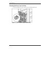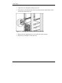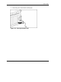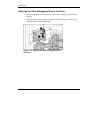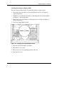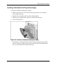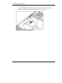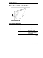
1
HP ProLiant DL585 Server
User Guide
July 2004 (Third Edition)
Part Number 358707-003
© 2004 Hewlett-Packard Development Company, L.P.
Microsoft, Windows, and Windows NT are trademarks of Microsoft Corporation in the U.S.
and other countries.
AMD, Opteron, and HyperTransport are trademarks of AMD Corporation in the U.S. and
other countries.
Hewlett-Packard Company shall not be liable for technical or editorial errors or omissions
contained herein. The information in this document is provided “as is” without warranty of
any kind and is subject to change without notice. The warranties for HP products are set forth
in the express limited warranty statements accompanying such products. Nothing herein
should be construed as constituting an additional warranty.
HP ProLiant DL585 Server User Guide
July 2004 (Third Edition)
Part Number 358707-003
Contents
About This Guide
Audience Assumptions...................................................................................................... xi
Important Safety Information ............................................................................................ xi
Symbols on Equipment ..................................................................................................... xi
Rack Stability .................................................................................................................. xiii
Symbols in Text............................................................................................................... xiii
Related Documents.......................................................................................................... xiv
Getting Help .................................................................................................................... xiv
Technical Support ..................................................................................................... xiv
HP Website .................................................................................................................xv
Authorized Reseller ....................................................................................................xv
Reader’s Comments ..........................................................................................................xv
Chapter 1
Server Features
Chapter 2
Server Operations
Powering Up the Server................................................................................................... 2-1
Powering Down the Server.............................................................................................. 2-1
Locating and Removing the Torx T-15 Tool ............................................................ 2-3
Extending the Server from the Rack ......................................................................... 2-4
Removing the Access Panel ............................................................................................ 2-7
Installing the Access Panel ....................................................................................... 2-8
HP ProLiant DL585 Server User Guide
iii
Contents
Chapter 3
Server Setup
Optional Installation Services ..........................................................................................3-1
Rack Planning Resources.................................................................................................3-2
Optimum Environment ....................................................................................................3-3
Space and Airflow Requirements..............................................................................3-3
Temperature Requirements .......................................................................................3-4
Power Requirements..................................................................................................3-5
Grounding Requirements ..........................................................................................3-6
Rack Warnings and Cautions...........................................................................................3-7
Installing Hardware Options ............................................................................................3-7
Removing Shipping Bracket from PCI Slots ...................................................................3-8
Server Shipping Contents ................................................................................................3-8
Installing the Server into the Rack.................................................................................3-10
Connecting the Power Cord and Peripheral Devices .....................................................3-17
Connecting the Power Cord ....................................................................................3-18
Attaching the Cable Management Arm .........................................................................3-20
Attaching the Cable Management Arm to a Square-Hole Rack..............................3-20
Attaching the Cable Management Arm to a Round-Hole Rack ..............................3-21
Attaching the Cable Management Arm to the Server .............................................3-24
Securing the Cables to the Cable Management Arm...............................................3-25
Powering Up and Configuring the Server......................................................................3-27
Installing the Operating System.....................................................................................3-27
Registering the Server....................................................................................................3-28
Routine Maintenance .....................................................................................................3-28
Chapter 4
Hardware Options Installation
Processor Memory Boards...............................................................................................4-2
Processor Memory Board Population Guidelines .....................................................4-2
Memory Options ..............................................................................................................4-5
Minimum Memory Requirements .............................................................................4-5
Memory Population Guidelines.................................................................................4-6
Internal Storage and Media Areas....................................................................................4-7
Locating the Internal Storage and Universal Media Drives ......................................4-7
Hot-Plug SCSI Hard Drive Options ..........................................................................4-8
Universal Media Bays .............................................................................................4-14
Hot-Plug Fans ................................................................................................................4-18
iv
HP ProLiant DL585 Server User Guide
Contents
Locating Hot-Plug Fans .......................................................................................... 4-18
Replacing a Hot-Plug Fan....................................................................................... 4-19
Hot-Plug Power Supplies .............................................................................................. 4-21
Locating the Power Supplies .................................................................................. 4-21
Removing a Redundant Hot-Plug Power Supply or Blank..................................... 4-22
Installing a Redundant Hot-Plug Power Supply ..................................................... 4-23
PCI-X Expansion Boards .............................................................................................. 4-25
Performance Balancing........................................................................................... 4-26
Installing an Expansion Board ................................................................................ 4-27
Battery-Backed Write Cache Enabler (BBWCE).......................................................... 4-30
Installing the Battery-Backed Write Cache Enabler ............................................... 4-31
Chapter 5
Server Configuration and Utilities
ROM-Based Setup Utility ............................................................................................... 5-2
Navigating RBSU ..................................................................................................... 5-2
Saving RBSU Configuration Settings....................................................................... 5-3
Using RBSU ............................................................................................................. 5-3
Enhanced Auto-Configuration Process ......................................................................... 5-10
Integrated Lights-Out Technology ................................................................................ 5-11
iLO ROM-Based Setup Utility...................................................................................... 5-11
Redundant ROM Support .............................................................................................. 5-12
Safety and Security Benefits................................................................................... 5-12
Access to Redundant ROM Settings....................................................................... 5-13
ROMPaq Utility ............................................................................................................ 5-13
Smart Components for Remote ROM Flash ................................................................. 5-14
ROM Legacy USB Support........................................................................................... 5-15
ProLiant Essentials Foundation Pack ............................................................................ 5-16
Ships as Standard .................................................................................................... 5-16
Single Source .......................................................................................................... 5-16
Regular Updates...................................................................................................... 5-16
Subscription Service ............................................................................................... 5-17
SmartStart Scripting Toolkit.......................................................................................... 5-17
HP Systems Insight Manager ........................................................................................ 5-18
HP Insight Diagnostics Utility....................................................................................... 5-18
Automatic Server Recovery .......................................................................................... 5-18
Integrated Management Log.......................................................................................... 5-19
HP ProLiant DL585 Server User Guide
v
Contents
Appendix A
Regulatory Compliance Notices
Regulatory Compliance Model Number......................................................................... A-1
Federal Communications Commission Notice ............................................................... A-1
Class A Equipment................................................................................................... A-2
Class B Equipment ................................................................................................... A-2
Declaration of Conformity for Products Marked with the FCC Logo, United States
Only.......................................................................................................................... A-3
Modifications ........................................................................................................... A-3
Cables ....................................................................................................................... A-4
Canadian Notice (Avis Canadien) .................................................................................. A-4
Class A Equipment................................................................................................... A-4
Class B Equipment ................................................................................................... A-4
Mouse Compliance Statement ........................................................................................ A-4
European Union Notice .................................................................................................. A-5
Japanese Notice............................................................................................................... A-6
BSMI Notice ................................................................................................................... A-6
Korean Notices ............................................................................................................... A-7
Class A Equipment................................................................................................... A-7
Class B Equipment ................................................................................................... A-7
Laser Compliance ........................................................................................................... A-8
Battery Replacement Notice ........................................................................................... A-9
Appendix B
Electrostatic Discharge
Preventing Electrostatic Damage.................................................................................... B-1
Grounding Methods ........................................................................................................ B-2
Appendix C
System Battery
Battery Replacement....................................................................................................... C-1
Appendix D
Cabling Guidelines
Cabling a SCSI Controller .............................................................................................. D-1
Cabling an Optional SCSI Controller to the 4 x 1 Drive Cage in Duplex Mode ..... D-1
Cabling an Optional SCSI Controller to the 4 x 1 Drive Cage in Simplex Mode.... D-2
Cabling the Battery-Backed Write Cache Enabler ......................................................... D-2
vi
HP ProLiant DL585 Server User Guide
Contents
Appendix E
System LEDs and Switches
System LEDs...................................................................................................................E-1
Front Panel LEDs ............................................................................................................E-2
Hot-Plug SCSI Hard Drive LEDs....................................................................................E-3
Hot-Plug Fan LED...........................................................................................................E-5
Hot-Plug Power Supply LEDs.........................................................................................E-6
NIC LEDs........................................................................................................................E-7
Battery-Backed Write Cache Enabler .............................................................................E-8
QuickFind Diagnostic Display ......................................................................................E-10
System Board Switches .................................................................................................E-13
System Maintenance Switch (SW3) .......................................................................E-14
System ID switch (SW4) ........................................................................................E-16
iLO/Redundant ROM Override Switch (SW5).......................................................E-17
Appendix F
Server Error Messages
Appendix G
Server Specifications
Server Specifications ...................................................................................................... G-1
Appendix H
Troubleshooting
If the Server Does Not Start ........................................................................................... H-3
Diagnostic Steps ............................................................................................................. H-5
Problems After Initial Boot .......................................................................................... H-13
Other Information Resources ....................................................................................... H-16
Index
List of Figures
2-1
2-2
2-3
2-4
Identifying the UID LED (1) and Power On/Standby buttons (2) ............................ 2-2
Removing the Torx T-15 tool ................................................................................... 2-3
Loosening the front panel thumbscrews ................................................................... 2-4
Extending the server from the rack ........................................................................... 2-5
HP ProLiant DL585 Server User Guide
vii
Contents
2-5
2-6
3-1
3-2
3-3
3-4
3-5
3-6
3-7
3-8
3-9
3-10
3-11
3-12
3-13
3-14
3-15
3-16
3-17
3-18
3-19
3-20
3-21
3-22
3-23
4-1
4-2
4-3
4-4
4-5
4-6
4-7
4-8
4-9
4-10
4-11
4-12
4-13
4-14
viii
Sliding the server into the rack..................................................................................2-6
Removing the access panel........................................................................................2-7
Removing the shipping bracket .................................................................................3-8
Rack-mounting hardware ..........................................................................................3-9
Measuring with the template ...................................................................................3-10
Pulling the rail compression lever ...........................................................................3-11
Inserting the rail tabs on the rear of the rack ...........................................................3-11
Inserting the rail tabs on the front of the rack .........................................................3-12
Attaching a server rail to the server.........................................................................3-13
Locking the inner slide rails into place ...................................................................3-14
Loading the server onto the rack rails .....................................................................3-15
Sliding the server to the rear of the rack..................................................................3-16
Tightening the thumbscrews ...................................................................................3-16
Rear panel components ...........................................................................................3-17
Connecting the power cord......................................................................................3-18
Securing the power cord..........................................................................................3-19
Securing the cable management arm to the square-hole rack .................................3-20
Removing the square-hole bracket ..........................................................................3-21
Attaching the round-hole bracket to the cable management arm ............................3-22
Attaching the cable management arm to the round-hole rack .................................3-23
Attaching the cable management arm to the server.................................................3-24
Aligning the cable management arm pivot points...................................................3-25
Pivoting the cable management arm .......................................................................3-25
Securing cables to the cable management arm........................................................3-26
Closing the cable management arm.........................................................................3-26
Locating the processor memory boards.....................................................................4-3
Installing a processor memory board ........................................................................4-4
DIMM slots ...............................................................................................................4-6
Internal storage and universal media drives ..............................................................4-7
Hot-plug SCSI hard drives and SCSI ID numbers ....................................................4-9
Removing a drive blank ..........................................................................................4-10
Removing a nonfunctioning SCSI hard drive .........................................................4-11
Installing a hot-plug SCSI hard drive......................................................................4-12
Locating the simplex/duplex switch........................................................................4-13
Locating the universal media bays ..........................................................................4-14
Removing a drive from bay 1..................................................................................4-15
Removing a drive from bay 2..................................................................................4-16
Installing a universal media drive ...........................................................................4-17
Hot-plug fans...........................................................................................................4-18
HP ProLiant DL585 Server User Guide
Contents
4-15
4-16
4-17
4-18
4-19
4-20
4-21
4-22
4-23
4-24
4-25
4-26
4-27
4-28
4-29
C-1
C-2
C-3
F
D-2
D-3
E-1
E-2
E-3
E-4
E-5
E-6
E-7
E-8
E-9
E-10
Removing a hot-plug fan ........................................................................................ 4-19
Installing a hot-plug fan .......................................................................................... 4-20
Locating the power supplies ................................................................................... 4-21
Removing a power supply or blank ........................................................................ 4-22
Installing a redundant hot-plug power supply......................................................... 4-23
Connecting the power cord to AC inlet 2 ............................................................... 4-24
Securing the power cord ......................................................................................... 4-24
PCI-X expansion slots and buses ............................................................................ 4-25
Releasing the expansion slot latch and removing the expansion slot cover............ 4-27
Locking the PCI-X retaining clip open ................................................................... 4-28
Installing a PCI-X expansion board ........................................................................ 4-28
Securing the PCI-X retaining clip........................................................................... 4-29
Removing the front fan cage................................................................................... 4-31
Installing the BBWCE ............................................................................................ 4-32
Connecting the cable to the BBWCE...................................................................... 4-33
Battery location on the system board........................................................................C-2
Removing a battery ...................................................................................................C-2
Installing a new battery.............................................................................................C-3
D-1
Cabling a SCSI controller (simplex mode) .............................................................. D-2
Cabling the BBWCE module to the 5i Plus Memory Module................................. D-2
Front panel LEDs......................................................................................................E-2
Hot-plug SCSI hard drive LEDs ...............................................................................E-3
Hot-plug fan LED .....................................................................................................E-5
Hot-plug power supply LEDs ...................................................................................E-6
NIC LEDs .................................................................................................................E-7
BBWCE LEDs ..........................................................................................................E-8
QuickFind Diagnostic Display LEDs .....................................................................E-10
System maintenance switch (SW3) ........................................................................E-14
System ID switch (SW4) ........................................................................................E-16
iLO/ Redundant ROM Override switch (SW5) ......................................................E-17
List of Tables
3-1
3-2
4-1
4-2
Rack-Mounting Hardware ........................................................................................ 3-9
Rear Panel Components.......................................................................................... 3-17
Processor Memory Boards........................................................................................ 4-3
Processor Memory Board Memory Banks................................................................ 4-6
HP ProLiant DL585 Server User Guide
ix
Contents
4-3
4-4
4-5
4-6
4-7
4-8
5-1
E-1
E-2
E-3
E-4
E-5
E-6
E-7
E-8
E-9
E-10
E-11
G-1
H-1
H-2
H-3
H-4
H-5
H-6
H-7
H-8
x
Internal Storage and Universal Media Drives ...........................................................4-7
Hot-Plug SCSI Hard Drives and SCSI ID Numbers .................................................4-9
Universal Media Bays .............................................................................................4-14
Hot-Plug Fans..........................................................................................................4-18
Power Supplies ........................................................................................................4-21
PCI-X Expansion Slots and Buses ..........................................................................4-25
RBSU Default Settings..............................................................................................5-8
Front Panel LEDs ..................................................................................................... E-2
Hot-Plug SCSI Hard Drive LEDs ............................................................................ E-3
Hot-Plug SCSI Hard Drive LED Combinations....................................................... E-4
Hot-Plug Fan LED ................................................................................................... E-5
Hot-Plug Power Supply LED Combinations............................................................ E-6
NIC LEDs................................................................................................................. E-7
BBWCE LED Descriptions...................................................................................... E-8
QuickFind Diagnostic Display LEDs..................................................................... E-10
System Maintenance Switch (SW3)....................................................................... E-14
System ID Switch (SW4) ....................................................................................... E-16
iLO/ Redundant ROM Override switch (SW5)...................................................... E-17
Server Specifications................................................................................................ G-1
Diagnostic Steps ....................................................................................................... H-5
Is the System Power LED Off? ................................................................................ H-6
Is the System Power LED Green? ............................................................................ H-7
Is the External Health LED Green?.......................................................................... H-8
Is the Internal Health LED Green?........................................................................... H-9
Is the Monitor Displaying Information?................................................................. H-12
Problems After Initial Boot .................................................................................... H-13
Troubleshooting Resources .................................................................................... H-16
HP ProLiant DL585 Server User Guide
About This Guide
This guide provides step-by-step instructions for installation, and reference
information for operation, troubleshooting, and future upgrades for the HP ProLiant
DL585 server.
Audience Assumptions
This guide is for the person who installs, administers, and troubleshoots servers. HP
assumes you are qualified in the servicing of computer equipment and trained in
recognizing hazards in products with hazardous energy levels.
Important Safety Information
Before installing this product, read the Important Safety Information document
included with the server.
Symbols on Equipment
The following symbols may be placed on equipment to indicate the presence of
potentially hazardous conditions:
WARNING: This symbol, in conjunction with any of the following symbols,
indicates the presence of a potential hazard. The potential for injury exists if
warnings are not observed. Consult your documentation for specific details.
HP ProLiant DL585 Server User Guide
xi
About This Guide
This symbol indicates the presence of hazardous energy circuits or electric
shock hazards. Refer all servicing to qualified personnel.
WARNING: To reduce the risk of injury from electric shock hazards, do not
open this enclosure. Refer all maintenance, upgrades, and servicing to
qualified personnel.
This symbol indicates the presence of electric shock hazards. The area
contains no user or field serviceable parts. Do not open for any reason.
WARNING: To reduce the risk of injury from electric shock hazards, do not
open this enclosure
This symbol on an RJ-45 receptacle indicates a network interface connection.
WARNING: To reduce the risk of electric shock, fire, or damage to the
equipment, do not plug telephone or telecommunications connectors into this
receptacle.
This symbol indicates the presence of a hot surface or hot component. If this
surface is contacted, the potential for injury exists.
WARNING: To reduce the risk of injury from a hot component, allow the
surface to cool before touching.
These symbols, on power supplies or systems, indicate that the
equipment is supplied by multiple sources of power.
WARNING: To reduce the risk of injury from electric shock,
remove all power cords to completely disconnect power from the
system.
This symbol indicates that the component exceeds the recommended
weight for one individual to handle safely.
Weight in kg
Weight in lb
xii
WARNING: To reduce the risk of personal injury or damage to the
equipment, observe local occupational health and safety requirements
and guidelines for manual material handling.
HP ProLiant DL585 Server User Guide
About This Guide
Rack Stability
WARNING: To reduce the risk of personal injury or damage to the equipment,
be sure that:
•
The leveling jacks are extended to the floor.
•
The full weight of the rack rests on the leveling jacks.
•
The stabilizing feet are attached to the rack if it is a single-rack installation.
•
The racks are coupled together in multiple-rack installations.
•
Only one component is extended at a time. A rack may become unstable if
more than one component is extended for any reason.
Symbols in Text
These symbols may be found in the text of this guide. They have the following
meanings.
WARNING: Text set off in this manner indicates that failure to follow directions
in the warning could result in bodily harm or loss of life.
CAUTION: Text set off in this manner indicates that failure to follow directions could
result in damage to equipment or loss of information.
IMPORTANT: Text set off in this manner presents essential information to explain a concept
or complete a task.
NOTE: Text set off in this manner presents additional information to emphasize or supplement
important points of the main text.
HP ProLiant DL585 Server User Guide
xiii
About This Guide
Related Documents
For additional information on the topics covered in this guide, refer to the following
documentation:
•
The hardware installation and configuration poster that ships with the server
•
The documentation CD, which includes the following resources:
— Servers Troubleshooting Guide
— Smart Array 5i Plus Controller and Battery-Backed Write Cache Enabler
User Guide
— Integrated Lights-Out User Guide
— ROM-Based Setup Utility Guide
— Link to the maintenance and service guide
Getting Help
If you have a problem and have exhausted the information in this guide, you can get
further information and other help in the following locations.
Technical Support
In North America, call the HP Technical Support Phone Center at 1-800-652-6672.
This service is available 24 hours a day, 7 days a week. For continuous quality
improvement, calls may be recorded or monitored. Outside North America, call the
nearest HP Technical Support Phone Center. Telephone numbers for worldwide
Technical Support Centers are listed on the HP website, www.hp.com.
Be sure to have the following information available before you call HP:
xiv
•
Technical support registration number (if applicable)
•
Product serial number
•
Product model name and number
•
Applicable error messages
HP ProLiant DL585 Server User Guide
About This Guide
•
Add-on boards or hardware
•
Third-party hardware or software
•
Operating system type and revision level
HP Website
The HP website has information on this product as well as the latest drivers and flash
ROM images. You can access the HP website at www.hp.com.
Authorized Reseller
For the name of your nearest authorized reseller:
•
In the United States, call 1-800-345-1518.
•
In Canada, call 1-800-263-5868.
•
Elsewhere, see the HP website for locations and telephone numbers.
Reader’s Comments
HP welcomes your comments on this guide. Please send your comments and
suggestions by e-mail to [email protected].
HP ProLiant DL585 Server User Guide
xv
1
Server Features
The HP ProLiant DL585 server is the ideal solution for enterprise customers who
require a rack optimized, four-way server that delivers outstanding performance and
high levels of availability for highly complex, business-critical applications.
Outstanding performance levels are achieved through superior engineering design
and the use of such industry-standard technologies as:
•
AMD Opteron Processors with HyperTransport technology
IMPORTANT: Mixing processor speeds and cache sizes is not supported.
•
PC2100 and PC2700 ECC Double Data Rate (DDR) SDRAM
•
64-bit, PCI-X I/O subsystem
•
Dual embedded Gigabit Ethernet network interface controller (NIC) with PXE
support and WOL
•
Embedded Smart Array 5i Plus Controller with support for 64-MB fully
transportable with Battery-Backed Write Cache Enabler option
•
Redundant hot-pluggable fans with N+1 redundancy
•
Redundant hot-pluggable power supplies with optional power supply installed
HP ProLiant DL585 Server User Guide
1-1
Server Features
The ProLiant DL585 server achieves unparalleled ease of manageability and
serviceability with the following:
1-2
•
Integration of standard remote management capability through Integrated
Lights-Out (iLO) technology
•
Virtually toolless and cableless mechanical design
•
ROM-Based Setup Utility (RBSU)
•
Redundant ROM
•
Innovative advanced diagnostic capabilities (QuickFind Diagnostic Display) for
troubleshooting at the server level
•
Rapid deployment rack rails
•
Efficient and space-saving dense form factor [4U height is 17.8 cm (7 in)]
HP ProLiant DL585 Server User Guide
2
Server Operations
Powering Up the Server
To power up the server, press the Power/On Standby button.
Powering Down the Server
WARNING: To reduce the risk of personal injury, electric shock, or damage to
the equipment, remove the power cord to remove power from the server. The
front panel Power On/Standby button does not completely shut off system
power. Portions of the power supply and some internal circuitry remain active
until AC power is removed.
IMPORTANT: If installing a hot-plug device, it is not necessary to power down the server.
1. Back up the server data.
2. Shut down the operating system as directed by the operating system
documentation.
HP ProLiant DL585 Server User Guide
2-1
Server Operations
3. If the server is installed in a rack, press the UID LED button (1) on the front
panel. Blue LEDs illuminate on the front and rear of the server.
4. Press the Power On/Standby button (2) to place the server in standby mode.
When the server activates standby power mode, the system power LED changes
to amber.
Figure 2-1: Identifying the UID LED (1) and Power
On/Standby buttons (2)
5. If the server is installed in a rack, locate the server by identifying the illuminated
rear UID LED button.
6. Disconnect the power cords.
The system is now without power.
2-2
HP ProLiant DL585 Server User Guide
Server Operations
Locating and Removing the Torx T-15 Tool
1. Locate the Torx T-15 tool on the back of the server.
2. Slide the tool upward out of the retaining clips.
Figure 2-2: Removing the Torx T-15 tool
HP ProLiant DL585 Server User Guide
2-3
Server Operations
Extending the Server from the Rack
1. Loosen the thumbscrews that secure the server to the front of the rack.
Figure 2-3: Loosening the front panel thumbscrews
2-4
HP ProLiant DL585 Server User Guide
Server Operations
2. Extend the server on the rack rails until the server rail-release latches engage.
Figure 2-4: Extending the server from the rack
HP ProLiant DL585 Server User Guide
2-5
Server Operations
WARNING: Be careful when pressing the rail-release levers and sliding the
component into or out of the rack. The sliding rails could pinch your fingertips.
3. After performing the installation or maintenance procedure, press the rail-release
levers at the front of both server rails and slide the server into the rack.
Figure 2-5: Sliding the server into the rack
4. Secure the server by tightening the thumbscrews.
2-6
HP ProLiant DL585 Server User Guide
Server Operations
Removing the Access Panel
WARNING: Pressing the Power On/Standby button sets the server to the
standby position, which removes power from most areas of the server.
However, portions of the power supply and some internal circuitry remain
active until the AC power cord is removed.
WARNING: To reduce the risk of personal injury from hot surfaces, allow the
internal system components to cool before touching.
CAUTION: Electrostatic discharge can damage electronic components. Properly
ground yourself before beginning any installation procedure.
1. Power down the server. Refer to the “Powering Down the Server” section earlier
in this chapter.
2. Extend the server from the rack. Refer to the “Extending the Server from the
Rack” section earlier in this chapter.
3. Unlock the access panel latch (1).
4. Lift up on the latch (2) and remove the access panel (3).
Figure 2-6: Removing the access panel
HP ProLiant DL585 Server User Guide
2-7
Server Operations
Installing the Access Panel
1. Place the access panel on top of the server with the latch open. Allow the panel to
extend past the rear of the server approximately 1.25 cm (0.5 in).
2. Push down on the latch. The access panel slides to a closed position.
2-8
HP ProLiant DL585 Server User Guide
3
Server Setup
Optional Installation Services
You may choose to have HP install the system. The installation service can be
purchased as a Care Pack packaged service or as a customized service agreement to
meet your specific requirements. Some of the Care Pack services are as follows:
•
Hardware installation services
•
Hardware and operating system installation for ProLiant servers
•
Installation and start-up services for some operating systems
•
Installation and start-up services for HP Systems Insight Manager
This optional hardware installation service is available in all countries where HP has
a direct or indirect service presence. Service may be ordered from and directly
provided by an authorized service reseller or, in the United States only, service may
be ordered by calling 1-800-633-3600. In the United States, HP makes all the
arrangements to have the system installed by qualified guaranteed service providers.
For more information, refer to the HP website:
http://www.hp.com/hps
HP ProLiant DL585 Server User Guide
3-1
Server Setup
Rack Planning Resources
The rack resource kit ships with all HP 9000, 10000, and H9 series racks. A summary
of the content of each resource follows:
•
Custom Builder is a web-based service for configuring one or many racks. Rack
configurations can be created using:
— A simple, guided interface
— Build-it-yourself mode
For more information, refer to the HP website www.hp.com.
•
The Installing Rack Products video provides a visual overview of operations
required for configuring a rack with rack-mountable components. It also provides
the following important configuration steps:
— Planning the site
— Installing rack servers and rack options
— Cabling servers in a rack
— Coupling multiple racks
•
3-2
The Rack Products Documentation CD enables you to view, search, and print
documentation for HP and Compaq branded racks and rack options. It also helps
you set up and optimize a rack in a manner that best fits your environment.
HP ProLiant DL585 Server User Guide
Server Setup
Optimum Environment
When installing the ProLiant DL585 server in a rack, select a location that meets the
environmental standards described in the following sections.
Space and Airflow Requirements
To enable servicing and adequate airflow, observe the following spatial requirements
when deciding where to install the rack:
•
Leave a minimum clearance of 63.5 cm (25 in) in front of the rack.
•
Leave a minimum clearance of 76.2 cm (30 in) in the back of the rack.
•
Leave a minimum clearance of 121.9 cm (48 in) from the back of the rack to the
rear of another rack or row of racks.
HP servers draw in cool air through the front door and expel warm air through the
rear door. Therefore, the front and rear rack doors must be adequately ventilated to
allow ambient room air to enter the cabinet, and the rear door must be adequately
ventilated to enable the warm air to escape from the cabinet.
CAUTION: To prevent improper cooling and damage to the equipment, do not block
the ventilation openings.
HP ProLiant DL585 Server User Guide
3-3
Server Setup
The 9000 and 10000 Series racks provide proper server cooling from flow-through
perforations in the front and rear doors that provide 64 percent open area for
ventilation.
CAUTION: When using a Compaq branded 7000 Series rack, you must install the
high airflow rack door insert [P/N 327281-B21 (42U) and P/N 157847-B21 (22U)] to
provide proper front-to-back airflow and cooling.
CAUTION: If a third-party rack is used, observe the following additional
requirements to ensure adequate airflow and to prevent damage to the equipment:
•
Front and rear doors: If the 42U server rack includes closing front and rear
doors, you must allow 5,350 sq cm (830 sq in) of holes evenly distributed from
top to bottom to permit adequate airflow (equivalent to the required 64 percent
open area for ventilation).
•
Side: The clearance between the installed rack component and the side panels
of the rack must be a minimum of 7 cm (2.75 in).
Temperature Requirements
To ensure continued safe and reliable equipment operation, install or locate the
system in a well-ventilated, climate-controlled environment.
The maximum recommended ambient operating temperature (TMRA) for most
server products is 35°C (95°F). The temperature in the room where the rack is
located must not exceed 35°C (95°F).
CAUTION: To reduce the risk of damage to the equipment when installing thirdparty options:
3-4
•
Do not permit optional equipment to impede airflow around the server or to
increase the internal rack temperature beyond the server or to increase the
internal rack temperature beyond the maximum allowable limits.
•
Do not exceed the manufacturer’s recommended ambient operating temperature
(TMRA).
HP ProLiant DL585 Server User Guide
Server Setup
Power Requirements
The installation of this equipment shall be in accordance with local/regional electrical
regulations governing the installation of information technology equipment by
licensed electricians. This equipment is designed to operate in installations covered
by NFPA 70, 1999 Edition (National Electrical Code) and NFPA 75, 1992 Edition
(code for Protection of Electronic Computer/Data Processing Equipment). For
electrical power ratings on options, refer to the product rating label or the user
documentation supplied with that option.
WARNING: To reduce the risk of personal injury, fire, or damage to the
equipment, do not overload the AC supply branch circuit that provides power
to the rack. Consult the electrical authority having jurisdiction over the wiring
and installation requirements of your facility.
CAUTION: Protect the server from power fluctuations and temporary interruptions
with a regulating uninterruptible power supply (UPS). This device protects the
hardware from damage caused by power surges and voltage spikes and keeps the
system in operation during a power failure.
When installing more than one server, you may need to use additional power
distribution devices to safely provide power to all devices. Observe the following
guidelines:
•
The power load must be balanced between available AC supply branch circuits.
•
The overall system AC current load must not exceed 80 percent of the branch
circuit AC current rating.
•
Do not use common outlet strips for this equipment.
•
Provide a separate electrical circuit for the server.
HP ProLiant DL585 Server User Guide
3-5
Server Setup
Grounding Requirements
For proper operation and safety, the server must be properly grounded. In the United
States, you must install the equipment in accordance with NFPA 70, 1999 Edition
(National Electrical Code) Article 250 as well as any local and regional building
codes. In Canada, the equipment must be installed in accordance with Canadian
Standards Association, CSA C22.1, Canadian Electrical Code. In all other countries,
the installation must follow any regional or national electrical wiring codes, such as
the International Electrotechnical Commission (IEC) 364, parts 1 through 7.
Furthermore, you must ensure that all power distribution devices used in the
installation—such as branch wiring and receptacles—are listed or certified
grounding-type devices.
Because of the high ground leakage currents associated with multiple servers
connected to the same power source, HP recommends the use of a power distribution
unit (PDU) that is either permanently wired to the branch circuit of the building or
includes a nondetachable cord that is wired to an industrial-style plug. NEMA
locking-style plugs or those complying with IEC 60309 are considered suitable for
this purpose. HP does not recommend using common power outlet strips for this
equipment.
3-6
HP ProLiant DL585 Server User Guide
Server Setup
Rack Warnings and Cautions
WARNING: To reduce the risk of personal injury or equipment damage, be
sure that:
•
The leveling jacks are extended to the floor.
•
The full weight of the rack rests on the leveling jacks.
•
The stabilizers are attached to the rack for single-rack installation.
•
The racks are coupled together in multiple-rack installations.
•
Only one component is extended at a time. A rack may become unstable if more
than one component is extended for any reason.
WARNING: Always mount the heaviest item on the bottom of the rack and
work from the bottom to the top.
Installing Hardware Options
Install any hardware options before initializing the server. For options installation
information, refer to the option documentation. For server-specific information, refer
to Chapter 4, “Hardware Options Installation.”
HP ProLiant DL585 Server User Guide
3-7
Server Setup
Removing Shipping Bracket from PCI Slots
To remove the shipping bracket from the PCI Slots, loosen the thumbscrew and
remove and discard the shipping bracket.
Figure 3-1: Removing the shipping bracket
NOTE: The shipping bracket is used only to secure the PCI-X latches during shipment.
Server Shipping Contents
Unpack the server-shipping carton and locate the materials and documentation
necessary for installing the server. All the rack-mounting hardware necessary for
installing the server into the rack is included with the rack or the server.
The contents of the server-shipping carton include:
3-8
•
Server
•
Setup documentation, Documentation CD, and software products
•
Power cords
•
Rack-mounting hardware
HP ProLiant DL585 Server User Guide
Server Setup
In addition to these supplied items, you may need:
•
Application software diskettes
•
Options to be installed
Figure 3-2: Rack-mounting hardware
Table 3-1: Rack-Mounting Hardware
Item
Description
Item
Description
1
Rack rail assemblies (2)
4
Round-hole bracket
2
Server rails (2)
5
Square-hole bracket
3
Cable management arm
6
Rack template
HP ProLiant DL585 Server User Guide
3-9
Server Setup
Installing the Server into the Rack
Follow the steps in this section if you are installing the server into a rack with square
holes. If you are installing the server into a rack with round holes, order the
appropriate rack installation option kit, and then refer to the installation instructions
that ship with the option kit for more information.
If you are installing the server into a telco rack, order the appropriate option kit at the
RackSolutions.com website. Follow the server specific instructions on the website to
install the rack brackets. After installing the brackets, follow the steps in this section.
WARNING: When installing the server in a telco rack, be sure that the rack
frame is adequately secured to the top and bottom of the building structure.
1. Mark the rack.
WARNING: Always plan the rack installation so that the heaviest item is on the
bottom of the rack. Install the heaviest item first, and continue to populate the
rack from the bottom to the top.
Figure 3-3: Measuring with the template
3-10
HP ProLiant DL585 Server User Guide
Server Setup
2. From the front of the rack, identify the rear rack holes on the inside of the
vertical rack that you marked with the template.
3. Pull the rail compression lever toward you.
Figure 3-4: Pulling the rail compression lever
4. Insert the two rail tabs from the end of the rack rail assembly into the marked
holes on the inside of the rear of the rack.
Figure 3-5: Inserting the rail tabs on the rear of the rack
HP ProLiant DL585 Server User Guide
3-11
Server Setup
5. Adjust the rack rail depth by sliding it forward.
6. Insert the two rail tabs from the rack rail assembly into the marked holes on the
inside of the front of the rack.
Figure 3-6: Inserting the rail tabs on the front of the rack
7. Release the rail compression lever to seat the tabs in the rack post.
8. Repeat steps 2 through 7 for the other rail.
3-12
HP ProLiant DL585 Server User Guide
Server Setup
9. Attach the server rails to the server.
Figure 3-7: Attaching a server rail to the server
WARNING: The server is very heavy, up to 44.5 kg (98 lb). To reduce the risk
of personal injury or damage to the equipment:
•
Remove all hot-plug power supplies to reduce the weight of the server
before lifting it.
•
Observe local occupational health and safety requirements and guidelines
for material handling.
•
Get help to lift and maneuver the server.
10. Remove the power supplies. For more information refer to “Removing a
Redundant Hot-Plug Power Supply or Blank” in Chapter 4, “Hardware Options
Installation.”
HP ProLiant DL585 Server User Guide
3-13
Server Setup
11. Pull the inner slide rail forward from each rack rail assembly until it locks into
place.
12. Slide the inner bearing brace forward until it stops.
Figure 3-8: Locking the inner slide rails into place
3-14
HP ProLiant DL585 Server User Guide
Server Setup
CAUTION: Keep the server parallel to the floor when sliding the server rails into the
standard rack rails. Tilting the server up or down can result in damage to the rails.
13. Lift the server using the four lift handles on the sides of the server.
14. Align the server and carefully insert the server rail into the inner slide rail until
the rail-release levers engage.
Figure 3-9: Loading the server onto the rack rails
HP ProLiant DL585 Server User Guide
3-15
Server Setup
15. Reach around the front of the server to press the rail-release levers at the front of
both server rails, and continue to slide the server into the rack.
Figure 3-10: Sliding the server to the rear of the rack
16. Tighten the thumbscrews to secure the server to the rack.
Figure 3-11: Tightening the thumbscrews
17. Reinstall the power supplies.
3-16
HP ProLiant DL585 Server User Guide
Server Setup
Connecting the Power Cord and Peripheral Devices
WARNING: To reduce the risk of electric shock or fire, do not plug
telecommunications/telephone connectors into the NIC connectors.
Figure 3-12: Rear panel components
Table 3-2: Rear Panel Components
Item
Description
1
Integrated Lights-Out Manager connector
2
USB connector 1
3
USB connector 2
4
Rear Unit Identification button and LED
5
Keyboard connector
6
Mouse connector
7
Video connector
8
Serial connector
9
NIC 2
10
NIC 1
11
AC inlet 1(primary)
12
AC inlet 2 (optional)
HP ProLiant DL585 Server User Guide
3-17
Server Setup
Connecting the Power Cord
WARNING: To reduce the risk of electric shock or damage to the equipment:
•
Do not disable the power cord grounding plug. The grounding plug is an
important safety feature.
•
Plug the power cord into a grounded (earthed) electrical outlet that is easily
accessible at all times.
•
Do not route the power cord where it can be walked on or pinched by items
placed against it. Pay particular attention to the plug, electrical outlet, and the
point where the cord extends from the server.
1. Plug the power cord in to the appropriate power supply AC power connector.
NOTE: The power connector for the primary power supply is inlet number one; the power
connector for the redundant hot-plug power supply is inlet number two.
Figure 3-13: Connecting the power cord
3-18
HP ProLiant DL585 Server User Guide
Server Setup
2. Secure the power cord with the retaining clip.
Figure 3-14: Securing the power cord
HP ProLiant DL585 Server User Guide
3-19
Server Setup
Attaching the Cable Management Arm
The cable management arm ships with a round-hole bracket and a square-hole
bracket. Use the appropriate bracket instructions for the server rack.
Attaching the Cable Management Arm to a Square-Hole Rack
1. Slide the bracket onto the rack.
2. Insert the bracket hooks into the square holes on the rack, and then push down to
secure.
3. Tighten the thumbscrew to stabilize the cable management arm on the rack.
Figure 3-15: Securing the cable management arm to the
square-hole rack
3-20
HP ProLiant DL585 Server User Guide
Server Setup
Attaching the Cable Management Arm to a Round-Hole Rack
1. Remove the square-hole bracket from the cable management arm by pulling out
the spring-activated fasteners, and then pulling out the bracket.
Figure 3-16: Removing the square-hole bracket
HP ProLiant DL585 Server User Guide
3-21
Server Setup
2. Attach the round-hole bracket by pulling out the spring-activated fasteners on the
cable management arm, and then inserting the bracket in between them.
Figure 3-17: Attaching the round-hole bracket to the
cable management arm
3. Slide the bracket onto the rack.
3-22
HP ProLiant DL585 Server User Guide
Server Setup
4. Attach the cable management arm to the round-hole rack, and then secure the
thumbscrews.
Figure 3-18: Attaching the cable management arm to
the round-hole rack
HP ProLiant DL585 Server User Guide
3-23
Server Setup
Attaching the Cable Management Arm to the Server
1. Loosen the thumbscrews on the front of the server to enable the server to slide
forward.
2. Align the keyholes on the cable management arm with the posts on the server,
and then secure with the thumbscrew.
Figure 3-19: Attaching the cable management arm to
the server
3-24
HP ProLiant DL585 Server User Guide
Server Setup
Securing the Cables to the Cable Management Arm
1. Align the pivot points of the cable management arm by sliding the server as
needed.
Figure 3-20: Aligning the cable management arm pivot
points
2. Pivot the arm away from the server.
Figure 3-21: Pivoting the cable management arm
HP ProLiant DL585 Server User Guide
3-25
Server Setup
3. Secure the cables to the inside of the cable management arm using the Velcro
straps.
Figure 3-22: Securing cables to the cable management
arm
4. Close the cable management arm and finish securing the cables.
Figure 3-23: Closing the cable management arm
5. Secure the server to the rack.
3-26
HP ProLiant DL585 Server User Guide
Server Setup
Powering Up and Configuring the Server
To power up the server, press the Power On/Standby button.
While the server boots, RBSU and the ORCA utility are automatically configured to
prepare the server for operating system installation. To configure these utilities
manually:
•
Press the F8 key when prompted during POST to configure the array controller
using ORCA. The array controller defaults to RAID 0 with one drive installed
and RAID 1 with more than one drive installed.
•
Press the F9 key when prompted during POST to change the server settings, such
as the settings for language and operating system, using RBSU. The system is set
up by default for the English language and a Microsoft Windows Server 2003
installation.
For more information about the automatic configuration, refer to the HP ROM Based
Setup Utility User Guide located on the Documentation CD.
Installing the Operating System
To operate properly, the server must have a supported operating system. For the latest
information on supported operating systems, refer to the HP website
http://hp.com/go/supportos
Two methods are available to install an operating system on the server:
•
SmartStart assisted installation—Insert the SmartStart CD into the CD-ROM
drive and reboot the server.
HP ProLiant DL585 Server User Guide
3-27
Server Setup
•
Manual Installation—Insert the operating system CD into the CD-ROM drive
and reboot the server. This process may require you to obtain additional drivers
from the HP website:
http://www.hp.com/support
Follow the on-screen instructions to begin the installation process.
For information on using these installation paths, refer to the SmartStart installation
poster in the ProLiant Essentials Foundation Pack, included with the server.
Registering the Server
Register the server at the HP website:
http://register.hp.com
Routine Maintenance
The HP ProLiant DL585 Server Maintenance and Service Guide provides specific
information required for general maintenance and component replacement, including:
•
Spare part numbers
•
Removal and replacement procedures
•
Diagnostic tools
The HP ProLiant DL585 Server Maintenance and Service Guide can be accessed
through the Documentation CD or the product website:
www.hp.com
3-28
HP ProLiant DL585 Server User Guide
4
Hardware Options Installation
If more than one option is being installed, read the installation instructions for all of
the hardware options and identify similar steps to streamline the installation process.
The following warnings apply to all procedures:
WARNING: To reduce the risk of personal injury from surfaces, allow the
drives and internal system components to cool before touching them.
CAUTION: To prevent damage to electrical components, properly ground the server
before beginning any installation procedure. Improper grounding can cause
electrostatic discharge.
HP ProLiant DL585 Server User Guide
4-1
Hardware Options Installation
Processor Memory Boards
The server supports up to four processor memory boards with AMD Opteron
processors.
CAUTION: Processor memory boards 1and 2 must always be installed. The system
will not boot if either board is missing.
CAUTION: Update the ROM to be sure that the system ROM recognizes the new
processor you are installing. For the most recent ROMPaq, refer to the HP website
and follow the support link on the product website.
Failure to flash the ROM before installing processor memory boards can cause
system failure.
IMPORTANT: Mixing processor speeds and cache sizes is not supported.
Processor Memory Board Population Guidelines
4-2
•
All processors must be of the same speed and cache size.
•
Processor memory boards 1 and 2 must always be installed.
•
Processor memory boards 3 and 4 must be installed as a pair.
HP ProLiant DL585 Server User Guide
Hardware Options Installation
Figure 4-1: Locating the processor memory boards
Table 4-1: Processor Memory Boards
Item
Description
1
Processor memory board slot 1 (processor)
2
Processor memory board slot 2 (boot processor)
3
Processor memory board slot 3 (air baffle)
4
Processor memory board slot 4 (air baffle)
To install a processor memory board:
1. Power down the server. Refer to “Powering Down the Server” in Chapter 2,
“Server Operations.”
2. Extend the server from the rack. Refer to “Extending the Server from the Rack”
in Chapter 2, “Server Operations.”
3. Remove the access panel. Refer to “Removing the Access Panel” in Chapter 2,
“Server Operations.”
HP ProLiant DL585 Server User Guide
4-3
Hardware Options Installation
4. Remove the air baffle.
NOTE: Do not discard the air baffle. Store for possible future use.
5. Install the new processor memory board.
Figure 4-2: Installing a processor memory board
6. Reinstall the access panel.
7. Restore the server to its operating position in the rack.
8. Power up the server.
NOTE: The ROM sets the processing frequency during the Power-On Self-Test (POST).
4-4
HP ProLiant DL585 Server User Guide
Hardware Options Installation
Memory Options
The server provides double data rate (DDR) synchronous dynamic RAM (SDRAM)
that can improve memory clock speed to:
•
At least 266 MHz with PC2100 DIMMs
•
At least 333 MHz with PC2700 DIMMs (2.4-GHz server models and above)
It activates output on both the rising and falling edge of the system clock rather than
on just the rising edge, potentially doubling output. The server features the following
advanced memory technologies:
•
Support for industry-standard registered ECC DDR SDRAM memory
— up to 48 GB at 333 MHz with PC2700 DIMMs
— up to 64 GB at 266 MHz with PC2100 or PC2700 DIMMs
•
Dual-channel memory architecture
Minimum Memory Requirements
•
Two DIMMs must be installed on the processor memory board in slot 2.
•
All DIMMs on a processor memory board must have the same part number.
NOTE: Processor memory boards in slots 1, 3, and 4 may be installed without memory;
however, this may not result in optimal performance.
HP ProLiant DL585 Server User Guide
4-5
Hardware Options Installation
Memory Population Guidelines
Supported configurations:
•
DIMMs on different processor memory boards can be of different sizes.
•
DIMMs on the same processor memory board must be of the same size and have
the same part number.
•
DIMMs must be installed on a processor memory board in pairs and in bank
order.
•
DIMMs must populate three or fewer banks on a memory board with PC2700
DIMMs to maintain a memory clock speed of 333 MHz.
Figure 4-3: DIMM slots
Table 4-2: Processor Memory Board Memory Banks
4-6
Slots
Bank
1-2
Bank 1
3-4
Bank 2
5-6
Bank 3
7-8
Bank 4
HP ProLiant DL585 Server User Guide
Hardware Options Installation
Internal Storage and Media Areas
The server ships standard with a diskette drive and an IDE CD-ROM drive in the
universal media bays. You can replace the CD-ROM or diskette drive with a DVD
drive, another diskette drive, or another CD-ROM drive.
Locating the Internal Storage and Universal Media Drives
Figure 4-4: Internal storage and universal media drives
Table 4-3: Internal Storage and Universal Media
Drives
Item
Description
1
Eject button for universal media bay 1
2
Universal media bay 1 (diskette drive)
3
Universal media bay 2 (CD-ROM drive)
4
Eject button for universal media bay 2
5–8
SCSI hot-plug hard drive bays 0 through 3
HP ProLiant DL585 Server User Guide
4-7
Hardware Options Installation
Hot-Plug SCSI Hard Drive Options
The server supports up to four hot-plug Ultra3 or Ultra320 drives. The embedded
Smart Array 5i Plus controller is Ultra3-based technology. For the drives to operate
at Ultra320 speeds, an optional PCI-X based Ultra320 SCSI controller needs to be
installed. The server ships in duplex configuration, but the SCSI backplane can be
configured for either simplex or duplex mode.
Installing a Hot-Plug Hard Drive into a Drive Bay
Installation of an optional hot-plug hard drive requires the following operations:
4-8
•
Determining the proper hot-plug hard drive installation order
•
Following the guidelines for installing SCSI devices
•
Installing a hot-plug hard drive
HP ProLiant DL585 Server User Guide
Hardware Options Installation
Determining the Proper Hot-Plug Hard Drive Installation Order
The system reads and manages the hot-plug hard drives based on the SCSI ID
number assigned to each drive. For optimal hard drive management and performance,
install the hard drives in the order of SCSI ID assignments. Always populate hard
drive bays starting with the lowest SCSI ID.
Figure 4-5: Hot-plug SCSI hard drives and SCSI ID
numbers
Table 4-4: Hot-Plug SCSI Hard Drives and SCSI ID Numbers
Item
Description
Simplex SCSI ID
Duplex SCSI ID
1
SCSI hard drive 1
0
0
2
SCSI hard drive 2
1
1
3
SCSI hard drive 3
2
0
4
SCSI hard drive 4
3
1
Note: Simplex configuration equals all four drives in the server connected to
one SCSI channel. Duplex configuration equals two drives per SCSI channel.
HP ProLiant DL585 Server User Guide
4-9
Hardware Options Installation
Guidelines for Installing SCSI Devices
The following guidelines apply for installing internal and external SCSI devices:
•
Mixing other drive standards degrades the overall performance of the drive
subsystem.
•
Using drives with the same capacity provides the greatest storage space
efficiency when the drives are grouped together into the same drive array.
Removing a Drive Blank
To remove a drive blank from the drive cage:
1. Squeeze the ejector levers.
2. Remove the blank.
Figure 4-6: Removing a drive blank
4-10
HP ProLiant DL585 Server User Guide
Hardware Options Installation
Removing a Nonfunctioning SCSI Hard Drive
To remove a nonfunctioning SCSI hard drive from the drive cage:
1. Press the ejector lever release button.
2. Pull the ejector lever open.
3. Remove the hard drive.
Figure 4-7: Removing a nonfunctioning SCSI hard drive
HP ProLiant DL585 Server User Guide
4-11
Hardware Options Installation
Installing a Hot-Plug SCSI Hard Drive
To install a hot-plug SCSI hard drive into the drive cage:
1. Press the ejector lever release button on the replacement hard drive to disengage
the lever.
2. Insert the hot-plug SCSI hard drive into the drive cage. Be sure that the drive
seats firmly into the connector on the SCSI backplane.
3. Close the ejector lever.
Figure 4-8: Installing a hot-plug SCSI hard drive
4. Be sure that the hot-plug hard drive activity LEDs on the front of the system are
illuminated green, indicating that the system is functioning properly. For detailed
information on LEDs, refer to Appendix E, “System LEDs and Switches.”
5. If any of the LEDs indicates an error, refer to Appendix H, “Troubleshooting,” or
refer to the HP Servers Troubleshooting Guide on the Documentation CD for
instructions.
4-12
HP ProLiant DL585 Server User Guide
Hardware Options Installation
Switching from Duplex to Simplex Mode
The server ships in duplex mode. To switch from duplex to simplex mode:
1. Power down the server. Refer to “Powering Down the Server” in Chapter 2,
“Server Operations.”
2. Extend the server from the rack. Refer to “Extending the Server from the Rack”
in Chapter 2, “Server Operations.”
3. Remove the access panel. Refer to “Removing the Access Panel” in Chapter 2,
“Server Operations.”
4. Locate the simplex/duplex switch.
Figure 4-9: Locating the simplex/duplex switch
5. Move the switch from duplex to simplex.
6. Reinstall the access panel.
7. Restore the server to its operating position in the rack.
8. Power up the server.
HP ProLiant DL585 Server User Guide
4-13
Hardware Options Installation
Universal Media Bays
The server supports installation of removable universal media drives into the
universal media bays. Drives supported include:
•
CD-ROM (standard)
•
Diskette (standard)
•
DVD (optional)
IMPORTANT: For the diskette drive to be bootable, it must be installed in the top universal
media bay (1). For the CD-ROM or DVD drive to be bootable, it must be installed in the bottom
universal media bay (2).
Figure 4-10: Locating the universal media bays
Table 4-5: Universal Media Bays
Item
4-14
Description
1
Eject button for universal media bay 1
2
Universal media bay 1 (diskette drive)
3
Universal media bay 2 (CD-ROM drive)
4
Eject button for universal media bay 2
HP ProLiant DL585 Server User Guide
Hardware Options Installation
Removing a Universal Media Drive
To remove a universal media drive:
1. Power down the server. Refer to “Powering Down the Server” in Chapter 2,
“Server Operations.”
2. Use the Torx T-15 tool to press the appropriate ejection button, and pull the
universal media drive out of the universal media bay. Refer to “Locating and
Removing the Torx T-15 Tool” in Chapter 2, “Server Operations.”
Figure 4-11: Removing a drive from bay 1
HP ProLiant DL585 Server User Guide
4-15
Hardware Options Installation
Figure 4-12: Removing a drive from bay 2
4-16
HP ProLiant DL585 Server User Guide
Hardware Options Installation
Installing a Universal Media Drive
To install a universal media drive:
1. Power down the server. Refer to “Powering Down the Server” in Chapter 2,
“Server Operations.”
2. Remove the existing universal media drive. Refer to the “Removing a Universal
Media Drive” section earlier in this chapter.
3. Insert the desired universal media drive into the universal media bay until it seats.
Figure 4-13: Installing a universal media drive
HP ProLiant DL585 Server User Guide
4-17
Hardware Options Installation
Hot-Plug Fans
The server supports redundant hot-plug fans in an N+1 configuration.
Locating Hot-Plug Fans
Figure 4-14: Hot-plug fans
Table 4-6: Hot-Plug Fans
Item
4-18
Description
Item
Description
1
Fan 1
5
Fan 5
2
Fan 2
6
Fan 6
3
Fan 3
7
Fan 7
4
Fan 4
8
Fan 8
HP ProLiant DL585 Server User Guide
Hardware Options Installation
Replacing a Hot-Plug Fan
To replace a hot-plug fan:
1. Extend the server from the rack. Refer to “Extending the Server from the Rack”
in Chapter 2, “Server Operations.”
2. Remove access panel. Refer to “Removing the Access Panel” in Chapter 2,
“Server Operations.”
3. Identify the nonfunctioning fan by checking for an amber LED on the QuickFind
Diagnostic Display or at the top of failed fan.
4. Remove the nonfunctioning fan.
Figure 4-15: Removing a hot-plug fan
HP ProLiant DL585 Server User Guide
4-19
Hardware Options Installation
5. Install fan.
Figure 4-16: Installing a hot-plug fan
6. Be sure that the LED on the fan is green.
7. Reinstall the access panel.
8. Restore the server to its operating position in the rack.
4-20
HP ProLiant DL585 Server User Guide
Hardware Options Installation
Hot-Plug Power Supplies
IMPORTANT: Do not install the power supplies until after the server is installed in the rack.
Leaving the power supplies out reduces the weight of the server for purposes of rack
installation.
The server supports a second hot-plug power supply to provide redundant power to
the system in the event of a failure in the primary power supply. You can install or
replace a second hot-plug power supply without powering down the server.
Locating the Power Supplies
Figure 4-17: Locating the power supplies
Table 4-7: Power Supplies
Item
Description
1
Hot-plug power supply 1 (primary)
2
Hot-plug power supply 2 (optional)
HP ProLiant DL585 Server User Guide
4-21
Hardware Options Installation
Removing a Redundant Hot-Plug Power Supply or Blank
To remove a redundant hot-plug power supply or blank:
1. If present, remove the Torx T-15 shipping screw from the bottom of the server
with the Torx T-15 tool that is located on the back of the server.
2. Press the release button on the locking lever upward.
3. Pull down on the locking lever.
4. Remove the power supply or blank out of the bay.
Figure 4-18: Removing a power supply or blank
4-22
HP ProLiant DL585 Server User Guide
Hardware Options Installation
Installing a Redundant Hot-Plug Power Supply
To install a redundant hot-plug power supply:
1. Remove the protective cover from the connector pins on the new redundant
power supply, if present.
2. Open the lever by pushing the lever release button upward.
3. Slide the power supply into the empty bay until it locks into place.
4. Close the locking lever.
Figure 4-19: Installing a redundant hot-plug power supply
5. For shipment or for optional added security, install the retaining screw, which
ships in a plastic bag with the power supply option kit. The pre-drilled hole for
the screw is located on the bottom of the server.
HP ProLiant DL585 Server User Guide
4-23
Hardware Options Installation
6. Connect the power cord to AC inlet 2.
Figure 4-20: Connecting the power cord to AC inlet 2
7. Secure the power cord with the retaining clip.
Figure 4-21: Securing the power cord
8. Be sure that the power LEDs on the power supply are green.
4-24
HP ProLiant DL585 Server User Guide
Hardware Options Installation
PCI-X Expansion Boards
The server supports the installation of both PCI and PCI-X expansion boards.
•
PCI 33-MHz and 66-MHz
•
PCI-X 66-MHz, 100-MHz, and 133-MHz
Figure 4-22: PCI-X expansion slots and buses
Table 4-8: PCI-X Expansion Slots and Buses
Item
Slot
Bus
Description
1
Slot 1
Fifth bus
133-MHz
2
Slot 2
Sixth bus
133-MHz
3
Slot 3
Seventh bus
100-Mhz
4
Slot 4
Seventh bus
100-Mhz
continued
HP ProLiant DL585 Server User Guide
4-25
Hardware Options Installation
Table 4-8: PCI-X Expansion Slots and Buses continued
Item
Slot
Bus
Description
5
Slot 5
Eighth bus
100-Mhz
6
Slot 6
Eighth bus
100-Mhz
7
Slot 7
Third bus
100-Mhz
8
Slot 8
Third bus
100-Mhz
Note: All PCI-X slots are 64-bit, 3.3-V keyed.
Performance Balancing
Balancing is the paired arrangement of expansion boards for optimal performance
based on the bus architecture of the expansion slots. Properly balancing the boards
across buses can improve performance. To balance expansion boards:
•
Populate slots 1 and 2 with 133-MHz PCI-X boards.
•
Populate slots 3-8 with 100-MHz PCI-X boards.
•
Populate slots across different buses before populating two slots on the same bus.
For more information about PCI-X bus architecture and numbering, refer to the white
paper, PCI Bus Numbering in a Windows NT Environment, on the HP website at:
www.hp.com
4-26
HP ProLiant DL585 Server User Guide
Hardware Options Installation
Installing an Expansion Board
CAUTION: To avoid risk of damage to the system or expansion boards, remove all
AC power cords before installing or removing non-hot-plug expansion boards. With
the front panel Power On/Standby button in the standby position, auxiliary power is
still connected to the expansion slots and may damage the board.
To install an expansion board:
1. Power down the server. Refer to “Powering Down the Server” in Chapter 2,
“Server Operations.”
2. Extend the server from the rack. Refer to “Extending the Server from the Rack”
in Chapter 2, “Server Operations.”
3. Remove the access panel. Refer to “Removing the Access Panel” in Chapter 2,
“Server Operations.”
4. Press down on the expansion slot latch to release it.
5. Open the latch.
6. Remove the expansion slot cover.
Figure 4-23: Releasing the expansion slot latch and
removing the expansion slot cover
HP ProLiant DL585 Server User Guide
4-27
Hardware Options Installation
7. If you are installing a full-length board, press the PCI-X retaining clip toward the
front of the server to lock it in the open position.
Figure 4-24: Locking the PCI-X retaining clip open
8. Install the expansion board in the slot and apply even pressure to seat the board
securely.
9. Close the expansion slot latch.
Figure 4-25: Installing a PCI-X expansion board
4-28
HP ProLiant DL585 Server User Guide
Hardware Options Installation
10. Close the PCI-X retaining clip (for full-length expansion boards only).
Figure 4-26: Securing the PCI-X retaining clip
11. Connect any required cables to the expansion board.
12. Reinstall the access panel.
13. Restore the server to its operating position in the rack.
14. Power up the server.
HP ProLiant DL585 Server User Guide
4-29
Hardware Options Installation
Battery-Backed Write Cache Enabler (BBWCE)
Features of the BBWCE include:
•
Protects against hard boot, power, controller, or system board failures
•
Provides up to 64-MB write cache memory protection (cache memory located on
the 5i Plus Memory Module)
•
Fully transportable to another ProLiant DL585 server in the data center
NOTE: In order to easily transport protected cache data to another ProLiant DL585
server, remove the BBWCE and the 5i Plus Memory Module simultaneously. The BBWCE
and 5i Plus Memory Module are connected to each other using a short cable.
•
Battery charge up to 72 hours
•
Battery life up to 3 years
The NiMH batteries in the battery module are continuously recharged through a
trickle charging process whenever the system power is on. Under normal operating
conditions, the battery module lasts 3 years before replacement is necessary.
4-30
HP ProLiant DL585 Server User Guide
Hardware Options Installation
Installing the Battery-Backed Write Cache Enabler
To install the BBWCE:
1. Power down the server. Refer to “Powering Down the Server” in Chapter 2,
“Server Operations.”
2. Extend the server from the rack. Refer to “Extending the Server from the Rack”
in Chapter 2, “Server Operations.”
3. Remove the access panel. Refer to “Removing the Access Panel” in Chapter 2,
“Server Operations.”
4. Remove all PCI-X cables and any cards that may be installed.
5. Remove all processor memory boards. Refer to the “Processor Memory Boards”
section earlier in this chapter.
6. Remove the front fan cage.
Figure 4-27: Removing the front fan cage
HP ProLiant DL585 Server User Guide
4-31
Hardware Options Installation
7. Align the BBWCE with the four standoffs along the inside wall of the chassis,
and press the enabler onto the standoffs until it is securely seated.
Figure 4-28: Installing the BBWCE
4-32
HP ProLiant DL585 Server User Guide
Hardware Options Installation
8. Connect the cable to the BBWCE (1) and to the 5i Plus Memory Module (2).
Figure 4-29: Connecting the cable to the BBWCE
9. Reverse the steps to restore the server.
Once the BBWCE is installed, it takes up to 24 hours to completely charge the
battery.
HP ProLiant DL585 Server User Guide
4-33
5
Server Configuration and Utilities
This chapter provides information about the following utilities and support tools:
•
ROM-Based Setup Utility (RBSU)
•
Enhanced Auto-Configuration Process
•
Integrated Lights-Out Technology
•
iLO ROM-Based Setup Utility
•
Redundant ROM Support
•
ROMPaq Utility
•
Smart Components for Remote ROM Flash
•
ROM Legacy USB Support
•
ProLiant Essentials Foundation Pack
•
SmartStart Scripting Toolkit
•
HP Systems Insight Manager (SIM)
•
HP Insight Diagnostics Utility
•
Automatic Server Recovery (ASR)
•
Integrated Management Log (IML)
HP ProLiant DL585 Server User Guide
5-1
Server Configuration and Utilities
ROM-Based Setup Utility
The RBSU is a configuration utility that is embedded in the server ROM. The RBSU
helps you configure certain server hardware settings and prepare the server for
operating system installation without using diskettes. The RBSU enables you to view
and establish server configuration settings during initial system startup, as well as
modify them after the server has been configured.
RBSU performs a wide range of configuration activities including:
•
Configuring system devices and installed options
•
Viewing system information
•
Selecting the operating system
•
Selecting the primary boot controller
•
Managing storage options
In addition, RBSU includes other features, which are outlined in the “Using RBSU”
section in this chapter.
Navigating RBSU
To navigate RBSU, use the following keys:
5-2
•
To access RBSU, press the F9 when prompted during POST.
•
To navigate the menu system, use the arrow keys.
•
To make selections, press the Enter key.
•
To exit RBSU, press the F10 key.
•
To return to the previous menu, press the Esc key.
HP ProLiant DL585 Server User Guide
Server Configuration and Utilities
Saving RBSU Configuration Settings
RBSU automatically saves settings when you press the Enter key. The utility does
not prompt you for confirmation of settings before you exit the utility. To change a
selected setting, you must select a different setting and press the Enter key.
Using RBSU
RBSU does not run automatically. The first time you power up the server, the system
defaults to Windows Server 2003 and waits so you can select a different operating
system by using RBSU. Press the F9 key when prompted during POST to enter
RBSU. While you are in RBSU, press any key to return to the RBSU main menu or
press the F10 key to exit RBSU.
NOTE: Most of the features in RBSU are not required in the setup of the server. The options
in this utility are designed to assist with specific server configuration issues.
RBSU is divided into a series of menu selections designed to configure specific areas
of the system. The primary menus are as follows:
•
System Options
•
PCI-X Devices
•
Standard Boot Order (IPL)
•
Date and Time
•
Server Passwords
•
Automatic Server Recovery
•
Server Asset Tags
•
Advanced Options
•
Utility Language
For a complete explanation of RBSU features and functions, refer to the ROM-Based
Setup Utility User Guide on the Documentation CD.
HP ProLiant DL585 Server User Guide
5-3
Server Configuration and Utilities
System Options
The System Options menu is for overall system configuration settings. The following
selections are included in this menu:
5-4
•
OS Selection prompts you to select the operating system. This option
automatically selects appropriate advanced settings for the selected operating
system and must be set before the operating system installation.
•
Embedded COM Port A enables you to either enable the embedded COM
port A at the specified resource setting or disable the option.
•
Embedded Mouse Port enables you to either enable the embedded mouse at the
specified resource setting or disable the option.
•
Integrated Diskette Controller enables you to enable or disable the floppy
controller.
•
NUMLOCK Power-On State enables you to enable or disable the keyboard
NUMLOCK feature at server startup.
•
Embedded NIC PXE Support enables you to enable or disable PXE support for
the NIC.
•
Diskette Write Control enables you to configure the write control of the
removable media drive (diskette drive). The options are read and write or read
only.
•
Diskette Boot Control enables you to have the system boot from the removable
media device (diskette drive).
HP ProLiant DL585 Server User Guide
Server Configuration and Utilities
PCI-X Devices
The PCI-X Devices menu option enables you to view and assign the IRQs for all
PCI-X devices.
Standard Boot Order (IPL)
The Standard Boot Order (IPL) menu option enables you to configure the order of
devices used to start an operating system. This feature can be set to select which
device the system scans first.
Date and Time
The Date and Time menu option enables you to set the system date and time.
Server Passwords
The Server Passwords menu enables you to set up passwords to limit access to the
system and its setup options. The following selections are available in this menu:
•
Administrator Password enables you to assign an administrator password. This
password prevents unauthorized users from modifying the setup options.
•
Power-On Password enables you to assign a power-on password. This password
prevents unauthorized users from powering on the system.
•
Network Server Mode enables the user to disable or enable the capability of the
system to boot with a locked keyboard or without a keyboard. To unlock the
keyboard, enter the Power-On Password.
•
QuickLock enables you to lock the keyboard and prompts you for the power-on
password to unlock the keyboard.
IMPORTANT: If you forget your password, you can clear all passwords by resetting the
system maintenance switch. Refer to “System Board Switches” in Appendix E, “System LEDs
and Switches.”
HP ProLiant DL585 Server User Guide
5-5
Server Configuration and Utilities
Automatic Server Recovery
The Automatic Server Recovery menu includes the following items:
•
Automatic Server Recovery enables you to enable or disable the Automatic
Server Recovery option.
•
Thermal Shutdown enables you to disable or enable the system automatic
shutdown feature caused by a thermal caution event. This option is enabled by
default. HP does not recommend disabling this feature.
Server Asset Tags
The Server Asset Tags menu enables you to access the Server Info Text. Server
Info Text enables you to identify the system with an Asset Tracking Number.
Advanced Options
The Advanced Options menu enables you to configure advanced options of the
system. The following selections are available in this menu:
5-6
•
MPS Table Mode enables you to change the APIC table setting. The APIC table
setting is automatically set by the OS Selection setting.
•
POST Speed Up enables you to enable or disable the complete memory test.
•
Wake On LAN enables you to enable or disable Wake On LAN Support.
•
Erase Non-Volatile Memory enables you to reset the configuration settings to
their factory defaults.
•
Node Interleaving enables you to enable or disable node interleaving.
•
Advanced ECC Support sets the system to use the standard four-way DIMM
configuration.
HP ProLiant DL585 Server User Guide
Server Configuration and Utilities
Utility Language
The Utility Language menu enables you to set the display language for RBSU. The
following choices are available:
•
English
•
French
•
Italian
•
German
•
Spanish
•
Japanese
Table 10-1 identifies the default settings for options in primary RBSU menus. For a
complete explanation of RBSU features and functions, refer to the ROM-Based Setup
Utility User Guide on the Documentation CD.
HP ProLiant DL585 Server User Guide
5-7
Server Configuration and Utilities
Table 5-1: RBSU Default Settings
Menu/Option
Default Setting
System Options
OS Selection
Embedded COM Port A
Integrated Diskette Controller
NUMLOCK Power-On State
NIC PXE Support
Diskette Read/Write Control
Diskette Boot Control
Windows Server 2003
COM 1; IRQ 4
Enabled
Off
Enabled
Read and write
Enabled
IPL Device Boot Order
CD-ROM
IPL: 1
Diskette Drive (A:)
IPL: 2
Hard Drive (C:)
IPL: 3
PXE
IPL: 4
Server Passwords
Set Administrator Password
None
Set Power-On Password
None
Network Server Mode
Disabled
QuickLock
Disabled
Automatic Server Recovery
ASR Status
ASR Timeout
Thermal Shutdown
Enabled
10 minutes
Enabled
continued
5-8
HP ProLiant DL585 Server User Guide
Server Configuration and Utilities
Table 5-1: RBSU Default Settings continued
Menu/Option
Default Setting
Server Asset Tags
Server Info Text
None
Advanced Options
MPS Table Mode
AutoSet Table
Post Speed Up
Enabled
POST F1 Prompt
Enabled
Wake On LAN
Disabled
ROM Selection
Use current ROM
Erase Non-volatile Memory
Off
Set CPU Corrected
None
(choose 1 or 2)
NMI Debug Button
Enabled
Custom POST Message
None
Advanced ECC Support
Enabled
HP ProLiant DL585 Server User Guide
5-9
Server Configuration and Utilities
Enhanced Auto-Configuration Process
During the power-up sequence that occurs the first time that the server is booted, the
system ROM automatically configures the entire system without any user
intervention.
By default setting, the system is configured for Microsoft® Windows® Server 2003.
To change any default settings in the auto-configuration process, load RBSU by
pressing the F9 key when prompted during POST. This allows you to select the
language, operating system, and primary boot controller for the server. Once these
settings are set according to your preference, exit RBSU and reboot the server.
The system then attempts to boot first from a bootable CD before booting from the
hard drive. For normal operating system installation, insert the operating system
installation CD into the CD-ROM drive. If ProLiant Essentials Foundation Pack
supports an assisted installation for the operating system you are installing, insert
ProLiant Essentials into the CD-ROM drive for an assisted installation.
If a POST error occurs, the system halts, pending a user selection from the menu. To
continue the boot process, press the F1 key, or select one of the other options on the
menu.
5-10
HP ProLiant DL585 Server User Guide
Server Configuration and Utilities
Integrated Lights-Out Technology
Integrated Lights-Out is a standard component of selected ProLiant servers that
provides server health and remote server manageability. The iLO subsystem includes
an intelligent microprocessor, secure memory, and a dedicated network interface.
This design makes iLO independent of the host server and its operating system. The
iLO subsystem provides remote access to any authorized network client, sends alerts,
and provides other server management functions.
Using iLO, you can:
•
Remotely power up, power down, or reboot the host server
•
Send alerts from iLO regardless of the state of the host server
•
Access advanced troubleshooting features through the iLO interface
•
Diagnose iLO using HP SIM through a Web browser and SNMP alerting
For more information about iLO features, refer to the Integrated Lights-Out User
Guide on the Documentation CD or on the HP website:
http://www.hp.com/servers/lights-out
iLO ROM-Based Setup Utility
HP recommends using iLO RBSU to configure and set up iLO. iLO RBSU is
designed to assist you with setting up iLO on a network; it is not intended for
continued administration.
To run iLO RBSU:
1. Restart or power up the server.
2. Press the F8 key when prompted during POST. The iLO RBSU runs.
3. Enter a valid iLO user ID and password with the appropriate iLO privileges
(Administer User Accounts, Configure iLO Settings). Default account
information is located on the iLO Default Network Settings tag.
4. Make and save any necessary changes to the iLO configuration.
HP ProLiant DL585 Server User Guide
5-11
Server Configuration and Utilities
5. Exit iLO RBSU.
HP recommends using DNS/DHCP with iLO to simplify installation. If DNS/DHCP
cannot be used, use the following procedure to disable DNS/DHCP and to configure
the IP address and the subnet mask:
1. Restart or power up the server.
2. Press the F8 key when prompted during POST. The iLO RBSU runs.
3. Enter a valid iLO user ID and password with the appropriate iLO privileges
(Administer User Accounts, Configure iLO Settings). Default account
information is located on the iLO Default Network Settings tag.
4. Select Network, DNS/DHCP, press the Enter key, and then select DHCP
Enable. Press the spacebar to turn off DHCP. Be sure that DHCP Enable is set
to Off and save the changes.
5. Select Network, NIC and TCP/IP, press the Enter key, and type the
appropriate information in the IP Address, Subnet Mask and Gateway IP
Address fields.
6. Save the changes. The iLO system automatically resets to use the new setup
when you exit iLO RBSU.
Redundant ROM Support
The ProLiant DL585 server enables you to upgrade or configure the ROM safely
with redundant ROM support. The server has 4 MB of ROM that acts as two separate
2-MB ROMs. In the standard implementation, one portion of the ROM contains the
current ROM program version, while another portion of the ROM contains a backup
version.
Safety and Security Benefits
When you flash the system ROM, ROMPaq writes over the backup ROM and saves
the current ROM as a backup, enabling you to switch easily to the existing ROM
version if the new ROM becomes corrupted for any reason. This feature protects the
existing ROM version, even if you experience a power failure while flashing the
ROM.
5-12
HP ProLiant DL585 Server User Guide
Server Configuration and Utilities
Access to Redundant ROM Settings
To access the redundant ROM:
1. Access RBSU by pressing the F9 key when prompted during POST.
2. Select Advanced Options.
3. Select Redundant ROM.
4. Select one of the ROM banks as the system ROM.
5. Press the Enter key.
6. Press the Esc key to exit the current menu or press the F10 key to exit RBSU.
7. Restart the server.
When the server boots, the system identifies whether the current ROM bank is
corrupt. If a corrupt ROM is detected, the system boots from the backup ROM and
alerts you through POST or IML that the ROM bank is corrupt.
ROMPaq Utility
Flash ROM enables you to upgrade the firmware (BIOS) with system or option
ROMPaq utilities. To upgrade the BIOS, insert a ROMPaq diskette into the diskette
drive and boot the system.
The ROMPaq Utility checks the system and provides a choice (if more than one
exists) of available ROM revisions. By default, the oldest ROM version is updated.
This procedure is the same for both system and option ROMPaq utilities.
If a power loss occurs during a firmware upgrade, redundant ROM support enables
data recovery.
HP ProLiant DL585 Server User Guide
5-13
Server Configuration and Utilities
Smart Components for Remote ROM Flash
Smart Components for Remote ROM Flash enables Microsoft Windows Server 2003
and Windows 2000 operating system administrators to efficiently upgrade and
manage system and array controller ROMs. This tool has the following features:
5-14
•
Works offline and online
•
Integrates with other HP software maintenance, deployment, and operating
system tools
•
Automatically checks for hardware, firmware, and operating system
dependencies, and installs only the correct ROM upgrades required by each
target server
HP ProLiant DL585 Server User Guide
Server Configuration and Utilities
ROM Legacy USB Support
When using operating systems that support USB, the ProLiant DL585 server supports
USB devices, including, but not limited to:
•
CD-ROM drives
•
Diskette drives
•
Keyboard
•
Mouse
For other operating systems, the ROM provides USB support for keyboard and
mouse, but not for CD-ROM or diskette drives.
ROM Legacy USB support is available during POST, DOS, and while the operating
system is running. The ROM does not support hot-plug events for the USB keyboard
or USB mouse at any time. The maximum device support is two USB keyboards, two
USB mouse devices, and one layer of hubs.
IMPORTANT: The ProLiant Essentials Foundation Pack Windows 95 environment does not
support a USB mouse. During the ProLiant Essentials process, you must use a legacy PS/2
mouse.
For a list of operating systems supported by the ProLiant DL585 server, refer to the
operating system support matrix on the product website at:
http://hp.com/go/supportos
To determine whether an operating system supports a particular feature, refer to the
operating system feature matrix on the operating system support page on the HP
website.
HP ProLiant DL585 Server User Guide
5-15
Server Configuration and Utilities
ProLiant Essentials Foundation Pack
The ProLiant Essentials Foundation Pack contains the essential software every
customer needs to install, configure, and manage ProLiant servers as part of an
adaptive infrastructure.
Ships as Standard
The foundation of an adaptive infrastructure is built upon the software contained in
the ProLiant Essentials Foundation Pack, which is provided with all ProLiant servers
at no charge. This software is an intrinsic component of every ProLiant solution.
Single Source
The Foundation Pack provides all the essential software needed to set up a reliable,
well-integrated, fully managed server. It includes the Management CD, which
contains the Intelligent Manageability products, including HP SIM, Management
Agents, and ActiveUpdate. For ProLiant DL585 servers, the Foundation Pack also
includes the SmartStart CD, which contains the SmartStart application and system
utilities and operating system support software. Appropriate instructions on how to
use the enclosed CDs as well as where to obtain additional information and any
required licenses are also provided to complete the Foundation Pack.
Regular Updates
The latest version of the software in the Foundation Pack can be accessed by visiting
the website:
http://www.compaq.com/manage
Complementing the Foundation Pack, you can also find and download several extra
tools there including:
•
5-16
SmartStart Scripting Toolkit - extending the power of SmartStart across largescale deployments of hundreds or thousands of servers
HP ProLiant DL585 Server User Guide
Server Configuration and Utilities
•
Integration Agents for HP SIM - for customers who have invested in popular
management frameworks, individual agents are available to integrate Intelligent
Management capabilities into those frameworks
•
Legacy Intelligent Manageability products - many legacy products that
originally shipped on the SmartStart or Management CDs can still be
downloaded from the web
Subscription Service
For more information or to apply, call 1-800-573-1099 or visit the website:
http://www.hp.com/servers/smartstart
SmartStart Scripting Toolkit
The SmartStart Scripting Toolkit is a set of DOS-based utilities that enables you to
configure and deploy servers in a customized, predictable, and unattended manner.
These utilities provide scripted server and array replication for mass server
deployment and duplicate the configuration of a configured source server onto target
systems with minimum user interaction.
The Configuration Replication Utility is a stand-alone DOS utility that duplicates the
settings of an operating RBSU-configured server by saving the server configuration
to a scripted file. You can edit and modify settings in the scripted file at the subset
level. For example, you can change ASR settings without having to change settings
for boot controller order.
For more information, refer to the SmartStart Scripting Toolkit User Guide.
HP ProLiant DL585 Server User Guide
5-17
Server Configuration and Utilities
HP Systems Insight Manager
HP SIM is a web-based application that allows system administrators to accomplish
normal administrative tasks from any remote location, using a web browser. HP SIM
provides device management capabilities that consolidate and integrate management
data from HP and third-party devices.
IMPORTANT: You must install and use HP SIM to benefit from the pre-failure warranties on
processors, hard drives, and memory modules.
For additional information, refer to the Management CD in the HP ProLiant
Essentials Foundation Pack.
HP Insight Diagnostics Utility
The HP Insight Diagnostics utility displays information about the server hardware
and tests the system to be sure it is operating properly. The utility has online help and
can be accessed using the SmartStart CD. Online Diagnostics for Microsoft®
Windows® is available for download from the HP website:
http://www.hp.com/support
Automatic Server Recovery
Automatic Server Recovery (ASR) is a feature that causes the system to restart when
a catastrophic operating system error occurs, such as a blue-screen, ABEND
(abnormal end), or panic. A system fail-safe timer, the ASR timer, starts when the
System Management driver, also known as the health driver, is loaded. When the
operating system is functioning properly, the system periodically resets the timer.
However, when the operating system fails, the timer expires and restarts the server.
ASR increases server availability by restarting the server within 10 minutes after a
system hang or shutdown. At the same time, the HP SIM console notifies you by
sending a message to a designated pager number that ASR has restarted the system.
You can disable ASR from the HP SIM console or RBSU.
5-18
HP ProLiant DL585 Server User Guide
Server Configuration and Utilities
Integrated Management Log
The IML records hundreds of events and stores them in an easy-to-view form. The
IML timestamps each event with 1-minute granularity.
You can view recorded events in the IML in several ways, including the following:
•
From within HP SIM
•
From within Survey Utility
•
From within operating system-specific IML viewers
— For NetWare: IML Viewer
— For Windows®: Event Viewer or IML Viewer
— For Linux: IML Viewer Application
•
From within HP Insight Diagnostics
For more information, refer to the Management CD in the HP ProLiant Essentials
Foundation Pack.
HP ProLiant DL585 Server User Guide
5-19
A
Regulatory Compliance Notices
Regulatory Compliance Model Number
For the purpose of regulatory compliance certifications and identification, your
product has been assigned a unique regulatory model number. The regulatory model
number can be found on the product nameplate label, along with all required
approval markings and information. When requesting compliance information for
this product, always refer to this regulatory model number. The regulatory model
number is not the marketing name or model number of the product.
Federal Communications Commission Notice
Part 15 of the Federal Communications Commission (FCC) Rules and Regulations
has established Radio Frequency (RF) emission limits to provide an interference-free
radio frequency spectrum. Many electronic devices, including computers, generate
RF energy incidental to their intended function and are, therefore, covered by these
rules. These rules place computers and related peripheral devices into two classes, A
and B, depending upon their intended installation. Class A devices are those that may
reasonably be expected to be installed in a business or commercial environment.
Class B devices are those that may reasonably be expected to be installed in a
residential environment (for example, personal computers). The FCC requires
devices in both classes to bear a label indicating the interference potential of the
device as well as additional operating instructions for the user.
HP ProLiant DL585 Server User Guide
A-1
Regulatory Compliance Notices
The FCC rating label on the device shows the classification (A or B) of the
equipment. Class B devices have an FCC logo or FCC ID on the label. Class A
devices do not have an FCC logo or FCC ID on the label. After the Class of the
device is determined, refer to the corresponding statement in the following sections.
Class A Equipment
This equipment has been tested and found to comply with the limits for a Class A
digital device, pursuant to Part 15 of the FCC Rules. These limits are designed to
provide reasonable protection against harmful interference when the equipment is
operated in a commercial environment. This equipment generates, uses, and can
radiate radio frequency energy and, if not installed and used in accordance with the
instructions, may cause harmful interference to radio communications. Operation of
this equipment in a residential area is likely to cause harmful interference, in which
case the user will be required to correct the interference at personal expense.
Class B Equipment
This equipment has been tested and found to comply with the limits for a Class B
digital device, pursuant to Part 15 of the FCC Rules. These limits are designed to
provide reasonable protection against harmful interference in a residential
installation. This equipment generates, uses, and can radiate radio frequency energy
and, if not installed and used in accordance with the instructions, may cause harmful
interference to radio communications. However, there is no guarantee that
interference will not occur in a particular installation. If this equipment does cause
harmful interference to radio or television reception, which can be determined by
turning the equipment off and on, the user is encouraged to try to correct the
interference by one or more of the following measures:
A-2
•
Reorient or relocate the receiving antenna.
•
Increase the separation between the equipment and receiver.
•
Connect the equipment into an outlet on a circuit that is different from that to
which the receiver is connected.
•
Consult the dealer or an experienced radio or television technician for help.
HP ProLiant DL585 Server User Guide
Regulatory Compliance Notices
Declaration of Conformity for Products Marked with the FCC Logo,
United States Only
This device complies with Part 15 of the FCC Rules. Operation is subject to the
following two conditions: (1) this device may not cause harmful interference, and (2)
this device must accept any interference received, including interference that may
cause undesired operation.
For questions regarding your product, contact us by mail or telephone:
•
Hewlett-Packard Company
P. O. Box 692000, Mail Stop 530113
Houston, Texas 77269-2000
•
1-800-652-6672 (For continuous quality improvement, calls may be recorded or
monitored.)
For questions regarding this FCC declaration, contact us by mail or telephone:
•
Hewlett-Packard Company
P. O. Box 692000, Mail Stop 510101
Houston, Texas 77269-2000
•
1-281-514-3333
To identify this product, refer to the part, regulatory model, or model number found
on the product.
Modifications
The FCC requires the user to be notified that any changes or modifications made to
this device that are not expressly approved by Hewlett-Packard Company may void
the user’s authority to operate the equipment.
HP ProLiant DL585 Server User Guide
A-3
Regulatory Compliance Notices
Cables
Connections to this device must be made with shielded cables with metallic RFI/EMI
connector hoods in order to maintain compliance with FCC Rules and Regulations.
Canadian Notice (Avis Canadien)
Class A Equipment
This Class A digital apparatus meets all requirements of the Canadian
Interference-Causing Equipment Regulations
Cet appareil numérique de la classe A respecte toutes les exigences du Règlement sur
le matériel brouilleur du Canada.
Class B Equipment
This Class B digital apparatus meets all requirements of the Canadian
Interference-Causing Equipment Regulations
Cet appareil numérique de la classe B respecte toutes les exigences du Règlement sur
le matériel brouilleur du Canada.
Mouse Compliance Statement
This device complies with Part 15 of the FCC Rules. Operation is subject to the
following two conditions: (1) this device may not cause harmful interference, and (2)
this device must accept any interference received, including interference that may
cause undesired operation
A-4
HP ProLiant DL585 Server User Guide
Regulatory Compliance Notices
European Union Notice
Products with the CE Marking comply with both the EMC Directive (89/336/EEC)
and the Low Voltage Directive (73/23/EEC) issued by the Commission of the
European Community.
Compliance with these directives implies conformity to the following European
Norms (the equivalent international standards are in parenthesis):
•
EN55022 (CISPR 22) – Electromagnetic Interference
•
EN55024 (IEC61000-4-2, 3, 4, 5, 6, 8, 11) – Electromagnetic Immunity
•
EN61000-3-2 (IEC61000-3-2) – Power Line Harmonics
•
EN61000-3-3 (IEC61000-3-3) – Power Line Flicker
•
EN60950 (IEC950) – Product Safety
HP ProLiant DL585 Server User Guide
A-5
Regulatory Compliance Notices
Japanese Notice
BSMI Notice
A-6
HP ProLiant DL585 Server User Guide
Regulatory Compliance Notices
Korean Notices
Class A Equipment
Class B Equipment
HP ProLiant DL585 Server User Guide
A-7
Regulatory Compliance Notices
Laser Compliance
This product may be provided with an optical storage device (that is, CD or DVD
drive) and/or fiber optic transceiver. Each of these devices contains a laser that is
classified as a Class 1 Laser Product in accordance with US FDA regulations and the
IEC 60825-1. The product does not emit hazardous laser radiation.
WARNING: Use of controls or adjustments or performance of procedures
other than those specified herein or in the laser product’s installation guide
may result in hazardous radiation exposure. To reduce the risk of exposure to
hazardous radiation:
•
Do not try to open the module enclosure. There are no user-serviceable
components inside.
•
Do not operate controls, make adjustments, or perform procedures to the
laser device other than those specified herein.
•
Allow only HP Authorized Service technicians to repair the unit.
The Center for Devices and Radiological Health (CDRH) of the U.S. Food and Drug
Administration implemented regulations for laser products on August 2, 1976. These
regulations apply to laser products manufactured from August 1, 1976. Compliance is
mandatory for products marketed in the United States.
A-8
HP ProLiant DL585 Server User Guide
Regulatory Compliance Notices
Battery Replacement Notice
Your computer is equipped with an internal lithium battery or battery pack. There is a
danger of explosion and risk of personal injury if the battery is incorrectly replaced or
mistreated. Unless specific replacement instructions are provided as part of this
guide, replacement is to be done by an authorized service provider using the HP spare
designated for this product. For more information about battery replacement or
proper disposal, contact your authorized reseller or your authorized service provider.
WARNING: Your computer contains an internal lithium battery or battery pack.
There is risk of fire and burns if the battery pack is not properly handled. To
reduce the risk of personal injury:
•
Do not attempt to recharge the battery.
•
Do not expose to temperatures higher than 60°C.
•
Do not disassemble, crush, puncture, short external contacts, or dispose of in
fire or water.
•
Replace only with the HP spare designated for this product.
Batteries, battery packs, and accumulators should not be disposed of
together with the general household waste. To forward them to recycling or
proper disposal, please use the public collection system or return them to
HP, your authorized HP partners, or their agents.
HP ProLiant DL585 Server User Guide
A-9
B
Electrostatic Discharge
To prevent damaging the system, be aware of the precautions you need to follow
when setting up the system or handling parts. A discharge of static electricity from a
finger or other conductor may damage system boards or other static-sensitive
devices. This type of damage may reduce the life expectancy of the device.
Preventing Electrostatic Damage
To prevent electrostatic damage, observe the following precautions:
•
Avoid hand contact by transporting and storing products in static-safe containers.
•
Keep electrostatic-sensitive parts in their containers until they arrive at static-free
workstations.
•
Place parts on a grounded surface before removing them from their containers.
•
Avoid touching pins, leads, or circuitry.
•
Always be properly grounded when touching a static-sensitive component or
assembly.
HP ProLiant DL585 Server User Guide
B-1
Electrostatic Discharge
Grounding Methods
There are several methods for grounding. Use one or more of the following methods
when handling or installing electrostatic-sensitive parts:
•
Use a wrist strap connected by a ground cord to a grounded workstation or
computer chassis. Wrist straps are flexible straps with a minimum of 1 megohm
± 10 percent resistance in the ground cords. To provide proper ground, wear the
strap snug against the skin.
•
Use heel straps, toe straps, or bootstraps at standing workstations. Wear the
straps on both feet when standing on conductive floors or dissipating floor mats.
•
Use conductive field service tools.
•
Use a portable field service kit with a folding static-dissipating work mat.
If you do not have any of the suggested equipment for proper grounding, have an
authorized reseller install the part.
NOTE: For more information on static electricity or for assistance with product installation,
contact your authorized reseller.
B-2
HP ProLiant DL585 Server User Guide
C
System Battery
The servers have memory devices that require a battery to retain stored information.
Battery Replacement
When the server no longer automatically displays the correct date and time, you may
need to replace the battery that provides power to the real-time clock. Under normal
use, battery life is usually about 5 to 10 years. Use an HP 220-mAh lithium, 3-volt
replacement battery
To install a new battery:
1. Power down the server. Refer to “Powering Down the Server” in Chapter 2,
“Server Operations.”
2. Extend the server from the rack. Refer to “Extending the Server from the Rack”
in Chapter 2, “Server Operations.”
3. Remove the access panel. Refer to “Removing the Access Panel” in Chapter 2,
“Server Operations.”
4. Locate the battery on the system board.
NOTE: It may be necessary to remove some PCI-X boards to gain access to the battery.
HP ProLiant DL585 Server User Guide
C-1
System Battery
Figure C-1: Battery location on the system board
5. Remove the existing battery.
Figure C-2: Removing a battery
C-2
HP ProLiant DL585 Server User Guide
System Battery
6. Install the new battery.
Figure C-3: Installing a new battery
7. Install the access panel.
8. Restore the server to its operating position in the rack.
9. Run the RBSU to reconfigure the system if the settings were lost.
HP ProLiant DL585 Server User Guide
C-3
D
Cabling Guidelines
Cabling a SCSI Controller
CAUTION: Route the SCSI cables through the SCSI cable guides on the front fan
cage to prevent damage to the SCSI cables.
Cabling an Optional SCSI Controller to the 4 x 1 Drive Cage in
Duplex Mode
Figure D-1: Cabling a SCSI controller (duplex mode)
HP ProLiant DL585 Server User Guide
D-1
Cabling Guidelines
Cabling an Optional SCSI Controller to the 4 x 1 Drive Cage in
Simplex Mode
Figure D-2: Cabling a SCSI controller (simplex mode)
Cabling the Battery-Backed Write Cache Enabler
Figure D-3: Cabling the BBWCE module to the 5i Plus
Memory Module
D-2
HP ProLiant DL585 Server User Guide
E
System LEDs and Switches
This appendix provides information about locating and using system LEDs and
switches in the server. For additional information about troubleshooting procedures,
refer to Appendix H, “Troubleshooting.”
System LEDs
The server contains several sets of LEDs that indicate the status and settings of
hardware components. This appendix discusses the following types and locations of
LEDs:
•
Front panel
•
Hot-plug SCSI hard drive
•
Hot-plug fans
•
Hot-plug power supplies
•
NIC
•
Battery-Backed Write Cache Enabler (BBWCE)
•
QuickFind Diagnostic Display
HP ProLiant DL585 Server User Guide
E-1
System LEDs and Switches
Front Panel LEDs
Figure E-1: Front panel LEDs
Table E-1: Front Panel LEDs
Item
1
Description
Status
Unit Identification
Blue = Activated
Blue flashing = System being managed remotely
Off = Deactivated
2
Internal health
3
External health
Green = Normal
Red = System critical
Amber = System degraded
Off = System off/Standby
4
Power
Green = On
Amber = Off (auxiliary power only)
Off = Power cord not attached to the server, or power supply failure
E-2
HP ProLiant DL585 Server User Guide
System LEDs and Switches
Hot-Plug SCSI Hard Drive LEDs
Figure E-2: Hot-plug SCSI hard drive LEDs
Table E-2: Hot-Plug SCSI Hard Drive LEDs
Item
1
Description
Status
Drive activity
On = Drive activity
Flashing = High activity on the
drive or drive is being configured
as part of an array
Off = No drive activity
2
Online status
On = Drive is part of an array and
is currently working
Flashing = Online activity
Off = No online activity
3
Fault status
On = Drive failure
Flashing = Fault-process activity
Off = No fault-process activity
HP ProLiant DL585 Server User Guide
E-3
System LEDs and Switches
Table E-3: Hot-Plug SCSI Hard Drive LED Combinations
E-4
Activity
LED
Online
LED
Fault
LED
Status
On
Off
Off
Do not remove the drive. Removing a drive during
this process causes data loss.
The drive is being accessed and is not configured as
part of an array.
On
Flashing
Off
Do not remove the drive. Removing a drive during
this process causes data loss.
The drive is rebuilding or undergoing capacity
expansion.
Flashing
Flashing
Flashing
Do not remove the drive. Removing a drive during
this process causes data loss.
The drive is part of an array being selected by the
Array Configuration Utility.
-OrThe Options ROMPaq is upgrading the drive.
Off
Off
Off
OK to replace the drive online if a predictive failure
alert is received (refer to “Hot-Plug Fan LED” for
details), and the drive is attached to an array
controller.
The drive is not configured as part of an array.
-OrIf this drive is part of an array, then a powered-on
controller is not accessing the drive.
-OrThe drive is configured as an online spare.
Off
Off
On
OK to replace the drive online.
The drive has failed and has been placed off-line.
Off
On
Off
OK to replace the drive online if a predictive failure
alert is received (refer to the following section for
details), provided that the array is configured for fault
tolerance and all other drives in the array are online.
The drive is online and configured as part of an array.
On or
flashing
On
Off
Do not remove the drive. Removing a drive during
this process causes data loss.
The drive is online and being accessed.
HP ProLiant DL585 Server User Guide
System LEDs and Switches
Hot-Plug Fan LED
Figure E-3: Hot-plug fan LED
Table E-4: Hot-Plug Fan LED
LED Status
Description
Off
Power is not applied to the fan
Green
Power is applied to the fan and the fan is
functional
Amber
Fan failure
HP ProLiant DL585 Server User Guide
E-5
System LEDs and Switches
Hot-Plug Power Supply LEDs
Figure E-4: Hot-plug power supply LEDs
Table E-5: Hot-Plug Power Supply LED Combinations
1 Power LED
(green)
2 Fault LED
(amber)
Status
Off
Off
No AC power
Off
On
No power to this specific power supply
-OrPower supply failure
Blinking
Off
AC power present
System in standby mode
E-6
On
Off
Power supply on and working properly
On
Blinking
Power supply current limit exceeded
HP ProLiant DL585 Server User Guide
System LEDs and Switches
NIC LEDs
Figure E-5: NIC LEDs
Table E-6: NIC LEDs
Item
Description
LED Color
Status
1
Activity LED
Green
On or flashing = network activity
Off = no network activity
2
Link LED
Green
On = linked to the network
Off = not linked to the network
HP ProLiant DL585 Server User Guide
E-7
System LEDs and Switches
Battery-Backed Write Cache Enabler
Figure E-6: BBWCE LEDs
Table E-7: BBWCE LED Descriptions
Server Status
LED Color
LED Status
Battery Module Status
Server is on and has
normal run time
Green (2)
On
Fast charging
Green (2)
Off
Trickle-charging
Amber (1)
On
Short in the connection of one or
more of the four button cells
within the battery module
Amber (1)
Blinking
Open in the circuit between the
positive and negative terminals of
the battery module
Amber (1)
Off
Battery module status is normal
continued
E-8
HP ProLiant DL585 Server User Guide
System LEDs and Switches
Table E-7: BBWCE LED Descriptions continued
Server Status
LED Color
LED Status
Battery Module Status
Server is on and is in the
first 30 seconds after
power-up
Amber (1) or
green (2)
On
Temporary lock-out state, data
was lost due to cable being
detached
Server is off and is in data
retention mode
Amber (1)
Blinking every
15 seconds
User data held in write cache is
being backed up
CAUTION: After the server is powered down, wait 15 seconds and then check the
illumination pattern of the LEDs before unplugging the cable from the battery module.
•
If the amber LED blinks after 15 seconds, do not remove the cable from the
battery module. This module is backing up data, and data will be lost if the cable
is detached.
•
If neither LED blinks after 15 seconds, it is safe to remove the cable from the
battery module.
When the server is on, review the POST message before plugging or unplugging the
cable from the battery module.
HP ProLiant DL585 Server User Guide
E-9
System LEDs and Switches
QuickFind Diagnostic Display
Figure E-7: QuickFind Diagnostic Display LEDs
Table E-8: QuickFind Diagnostic Display LEDs
Item
Description
Status
Action
1
Fan
Off = normal
Be sure fan is installed and seated
properly.
On = attention required
If fan is installed and seated properly,
replace the fan.
2
Processor
Off = normal
On = attention required
Processor pre-failure notification. Inspect
the IML logs and/or POST messages.
Processor may need to be replaced.
continued
E-10
HP ProLiant DL585 Server User Guide
System LEDs and Switches
Table E-8: QuickFind Diagnostic Display LEDs continued
Item
Description
Status
Action
3
Processor
memory board
Off = normal
Processor memory board power failure. If
problem persists, replace
processor/memory board.
Processor
power module
Off = normal
4
On = attention required
On = attention required
PPM power failure. If problem persists,
replace PPM.
If the PPM and the BRD LEDs are both on,
there is a configuration error.
5
Temperature
Off = normal
On = attention required
One or more components have
experienced an elevated temperature or a
thermal shutdown.
A thermal shutdown is indicated by the
Therm Trip LED.
•
Be sure the processor heatsink is
properly attached.
•
Be sure there are no 1.7" DIMMs
installed that prevent airflow across the
processor heatsink).
•
Be sure that all fans are installed and
working properly.
•
Be sure that the server environment
meets posted requirements.
For information about server environment
requirements refer to the “Optimum
Environment” section in Chapter 3.
6
DIMM
Off = normal
On = attention required
7
I/O power fault
Off = normal
On = attention required
DIMM failure or configuration error. Refer to
the IML or POST messages
A power fault on the system I/O board
occurred. If problem persists, replace the
system I/O board.
continued
HP ProLiant DL585 Server User Guide
E-11
System LEDs and Switches
Table E-8: QuickFind Diagnostic Display LEDs continued
Item
Description
Status
Action
8
Therm trip
Off = normal
The server experienced a thermal
shutdown.
On = attention required
If one of the CPU thermal LEDs is amber,
that CPU experienced an overtemperature
condition.
9
SCSI interlock
Off = normal
On = attention required
•
Make sure that the processor heatsink
is properly attached. For more
information, refer to the maintenance
and service guide.
•
Make sure the correct DIMMs (1.2"
tall) are installed.
•
Make sure all fans are installed and
working properly
Ensure the SCSI backplane is installed
properly.
Reseat SCSI backplane board and hard
drives.
10
Power supply 1
Off = normal
On = attention required
11
Power supply 2
Off = normal
On = attention required
12
Bus error
Look at the LEDs on the front of the power
supply and take the appropriate action.
Look at the LEDs on the front of the power
supply and take the appropriate action.
Off = normal
A bus error occurred.
On = attention required
The error may have been caused by one of
the adapter cards on this bus (see amber
LEDs for which slots may have caused the
error).
Reseat adapter cards.
If problem persists, remove/replace one or
both of the cards.
E-12
HP ProLiant DL585 Server User Guide
System LEDs and Switches
System Board Switches
Some server operations, including adding or removing a component or changing a
security feature, require that you reconfigure a system switch. If the system
configuration is incorrect, the server may not work properly and you may receive
error messages on the screen. Setting and verifying the system board switches is an
important part of the overall troubleshooting process.
The server has three switch banks:
•
System maintenance switch (SW3)
•
System ID switch (SW4)
•
iLO/ Redundant ROM Override switch (SW5)
This section provides figures and tables to identify the locations, positions, functions,
and settings for each of these switches.
HP ProLiant DL585 Server User Guide
E-13
System LEDs and Switches
System Maintenance Switch (SW3)
Figure E-8: System maintenance switch (SW3)
Table E-9: System Maintenance Switch (SW3)
Position Default
1
2
Function
Description
Settings
Enables or disables
configuration changes
in nonvolatile RAM
(NVRAM)
Open (off)
Reserved
Off
Lock
configuration
Configuration can be changed.
Closed (on)
Configuration is locked and cannot
be changed.
3
4
Reserved
Off
Diskette boot
override
Enables or disables
booting from diskette
drive
Both settings enable
you to read from and
write to the diskette
after the system
completes the boot
sequence.
Open (off)
The diskette drive boot is
controlled by the configuration.
Closed (on)
The diskette drive boots
regardless of the configuration.
continued
E-14
HP ProLiant DL585 Server User Guide
System LEDs and Switches
Table E-9: System Maintenance Switch (SW3) continued
Position Default
5
Off
Function
Description
Settings
Password
disable
Enables or disables
password protection.
Open (off)
Power-on password is enabled.
Closed (on)
Power-on password is disabled.
6
Off
Configuration
validation
Invalidates nonvolatile
RAM (NVRAM)
configuration
information
Open (off)
NVRAM is valid.
Closed (on)
NVRAM is invalid, and
configuration is lost.
7
Off
Reserved
8
Off
Reserved
CAUTION: When maintenance mode is turned on (the maintenance switch is set to
on/closed) and the system is powered up, NVRAM configuration is invalidated.
HP ProLiant DL585 Server User Guide
E-15
System LEDs and Switches
System ID switch (SW4)
Figure E-9: System ID switch (SW4)
Table E-10: System ID Switch (SW4)
E-16
Position
Description
1 through 3
Reserved
HP ProLiant DL585 Server User Guide
System LEDs and Switches
iLO/Redundant ROM Override Switch (SW5)
The iLO/ Redundant ROM Override switch (SW5) is a two-position switch that is
used for miscellaneous purposes. The iLO security override switch allows the
administrator full access to the iLO processor. This access is necessary if the
administrator lost their password or if the iLO boot-block needs to be flashed.
Figure E-10: iLO/ Redundant ROM Override switch
(SW5)
Table E-11: iLO/ Redundant ROM Override switch (SW5)
Position
Default
1
Off
Function
Description
Settings
iLO security
override
The override allows
the administrator full
access to the iLO
processor.
Open (off)
Normal
Closed (on)
Override
2
Off
Redundant
bootblock
select
Forces booting from
the redundant
bootblock
Open (off)
Normal
Closed (on)
Redundant bootblock (ROM)
HP ProLiant DL585 Server User Guide
E-17
F
Server Error Messages
Use POST error messages to assist in troubleshooting and performing basic
diagnostic functions in the server. For a complete listing of error messages and other
troubleshooting information, refer to the HP Servers Troubleshooting Guide provided
on the Documentation CD or online on the product page at www.hp.com.
HP ProLiant DL585 Server User Guide
F-1
G
Server Specifications
Server Specifications
This appendix provides operating and performance specifications for the server.
Table G-1: Server Specifications
Feature
Units
Dimensions
Height
17.5 cm (6.88 in)
Depth
69.2 cm (27.25 in)
Width
46.3 cm (19.0 in)
Weight
30.8 kg, minimum (68 lb, minimum)
44.5 kg, maximum (98 lb, maximum)
International input requirements
Rated input voltage
180 V to 264 V
Rated input frequency
47 Hz to 63 Hz
Rated input current
6A
U.S. input requirements
Rated input voltage
90 V to 132 V
Rate input frequency
47 Hz to 63 Hz
Rated input current
12 A
continued
HP ProLiant DL585 Server User Guide
G-1
Server Specifications
Table G-1: Server Specifications continued
Feature
Units
Power supply output power
Rated steady-state power
800 W
Maximum peak power
800 W
Temperature range
Operating
10° to 35°C (50° to 95°F)
Non-operating
-30° to 60°C (-20° to 140°F)
Relative humidity (non-condensing)
G-2
Operating
20% to 80%
Non-operating
5% to 90%
Maximum wet bulb temperature
38.7°C (101.7°F)
Heat dissipation
3900 BTU/Hr
HP ProLiant DL585 Server User Guide
H
Troubleshooting
This appendix provides specific troubleshooting information for the server. Use it to
find details about server startup and operation errors.
For information on LEDs and switches specific to the server, refer to Appendix E,
“System LEDs and Switches.”
For a more detailed discussion of troubleshooting techniques, diagnostic tools, error
messages, and preventative maintenance, refer to the HP Servers Troubleshooting
Guide included on the Documentation CD that ships with the server.
WARNING: A risk of personal injury exists from hazardous energy levels. The
installation of options and the routine maintenance and service of this product
shall be performed by individuals who are knowledgeable about the
procedures, precautions, and hazards associated with equipment containing
hazardous energy circuits.
HP ProLiant DL585 Server User Guide
H-1
Troubleshooting
This appendix includes the following topics:
•
If the Server Does Not Start
You are provided with initial instructions on what to try and where to go for help
for the most common problems encountered during the initial Power-On
Self-Test (POST). A successful startup requires the server to complete this test
each time you power up, before the server can load the operating system and start
running software applications.
•
Diagnostic Steps
If the server does not power up after you have performed initial troubleshooting
procedures, use the tables in this section to identify possible reasons for the
problem, possible solutions, and references to other sources of information.
•
Problems After Initial Boot
Once the server has passed the POST, you may still encounter errors, such as an
inability to load the operating system. You are provided with instructions on
what to try and where to go for help when you encounter errors after the server
completes the POST.
•
Other Information Resources
This section provides a list of reference information available for the server.
For troubleshooting information beyond the scope of this guide, both general and
specific to ProLiant DL585 servers, refer to Table H-8.
H-2
HP ProLiant DL585 Server User Guide
Troubleshooting
If the Server Does Not Start
This section provides systematic instructions on what to try and where to go for help
for the most common problems encountered during initial POST. The server must
first complete this test each time you power up, before it can load the operating
system and start running software applications.
WARNING: A risk of personal injury exists from hazardous energy levels. The
installation of options, and the routine maintenance and service of this product
shall be performed by individuals who are knowledgeable about the
procedures, precautions, and hazards associated with equipment containing
hazardous energy circuits.
If the server does not start:
1. Verify that the server and monitor are plugged into a working outlet.
2. Make sure that the power source is working properly:
a. Check the status using the system power LED.
b. Verify that the Power On/Standby button was pressed firmly.
3. Make sure that the power supplies are working properly by checking the power
supply LEDs.
NOTE: For more information about the location and status of LEDs, refer to Appendix E,
“System LEDs and Switches.” For more information about power, refer to the HP Servers
Troubleshooting Guide.
4. Check the interlock LEDs on the hood label. If any LEDs are amber, reseat the
component.
5. If the system does not complete POST or start loading an operating system, refer
to the HP Servers Troubleshooting Guide.
6. If the server is rebooting repeatedly, verify that the system is not rebooting due to
a problem that initiates an ASR-2 reboot. Some operating systems reboot server
when an error occurs. This is the default in Windows Server 2003.
7. Restart the server.
HP ProLiant DL585 Server User Guide
H-3
Troubleshooting
IMPORTANT: If the server does not restart, proceed to the following section, “Diagnostic
Steps.”
8. Check the server for the following normal power-up sequence to verify that the
system meets the minimal hardware requirements and is powered up during
normal operations:
a. The power button LED turns from standby (amber) to on (green).
b. The fans start up. It is normal for the fans to initially run at full speed and
then slow down.
9. Check the monitor for the following messages that verify the system meets the
minimal hardware requirements and is powered up during normal operations:
a. ProLiant logo
b. BIOS information
c. Copyright information
d. Processor initialization
e. Multi-initiator configuration
IMPORTANT: Select the multi-initiator configuration utility (CRTL-A) only to support HP
storage and clustering options.
f.
PXE initialization
g. Option ROMs
h. SCSI devices
10. The operating system loads to complete the boot process.
If the server completes POST and attempts to load the operating system, go to the
“Problems After Initial Boot” section in this appendix.
H-4
HP ProLiant DL585 Server User Guide
Troubleshooting
Diagnostic Steps
If the server does not power up, or powers up but does not complete POST, answer
the questions in Table H-1 to determine appropriate actions based on the symptoms
observed. The flow of questions reflects the usual flow of events during a power-on
sequence. A flow chart following this table illustrates the recommended diagnostic
steps and decision options.
According to the answers you give, you will be directed to an appropriate secondary
table in this section. The table outlines possible reasons for the problem, options
available to assist in diagnosis, possible solutions, and references to other sources of
information.
Table H-1: Diagnostic Steps
Question
Action
Question 1:
If no, continue to question 2.
Is the system power LED off?
If yes, refer to Table H-2.
Question 2:
If yes, continue to question 3.
Is the system power LED green?
If no, refer to Table H-3.
Question 3:
If yes, continue to question 4.
Is the external health LED green?
If no, refer to Table H-4.
Question 4:
If yes, continue to question 5.
Is the internal health LED green?
If no, refer to Table H-5.
Question 5:
If yes, use the POST messages for further
diagnosis. Refer to Table H-6 for details.
Is the monitor displaying information?
If no, refer to Table H-6.
HP ProLiant DL585 Server User Guide
H-5
Troubleshooting
Table H-2: Is the System Power LED Off?
Answer
Possible Reasons
Possible Solutions
Yes, it is off
The system is not connected to AC
power, or no AC power is available.
Be sure that the power cord is connected
to the power supply.
A power supply problem exists. The
power supply may not be connected
or inserted properly, it may have a
damaged connector, or it may have
failed.
Be sure that the power supply is
undamaged and fully seated, and then
verify that the power supply LED is green
when you power up the server. Refer to
Appendix E, “System LEDs and Switches,”
for locations and states.
A broken connection exists between
the front panel LED assembly and
the removable media board.
Be sure that the power switch cable
assembly is inserted properly to the
removable media board.
The front panel LED assembly has
failed.
Refer to the HP Servers Troubleshooting
Guide for further options.
If these solutions do not solve the
problem, contact an authorized service
provider for assistance.
No
If the system power button LED is amber,
press the Power On/Standby button.
Refer to Table H-3.
Note: For cabling configurations, refer to Appendix D, “Cabling Guidelines.” For LED locations and
functions, refer to Appendix E, “System LEDs and Switches.”
H-6
HP ProLiant DL585 Server User Guide
Troubleshooting
Table H-3: Is the System Power LED Green?
Answer
Possible Reasons
Possible Solutions
No, it is off
Power On/Standby button has not
been pressed firmly.
Firmly press the power button.
A power supply problem exists. The
power supply may not be connected or
inserted properly, it may have a
damaged connector, or it may have
failed.
Be sure that the power supply is
undamaged, the power supply is fully
seated, and the power supply LED is
green.
The system may have experienced a
short.
Check for bent connector pins and
improperly seated expansion boards.
The front panel LED assembly has
failed.
Be sure that the front panel LED
assembly cable is connected to the
power backplane.
If these solutions do not solve the
problem, contact an authorized
service provider for assistance.
Yes
If the system power button LED is
green, refer to Table H-4.
Note: For cabling configurations, refer to Appendix D, “Cabling Guidelines.” For LED locations and
functions, refer to Appendix E, “ System LEDs and Switches.”
HP ProLiant DL585 Server User Guide
H-7
Troubleshooting
Table H-4: Is the External Health LED Green?
Answer
Possible Reasons
Possible Solutions
No, it is
amber
One power supply has failed;
therefore, power supply
redundancy is lost.
Be sure that each installed power supply is
securely connected to an AC power source.
Locate the amber power supply LED to
identify the failed power supply.
Contact an authorized service provider for
replacement parts and service.
No, it is red
All installed power supplies have
experienced a failure.
Remove all AC power from power supplies
and reconnect to clear the error condition.
Replace the power supply. Contact an
authorized service provider for replacement
parts and service.
Yes
Refer to Table H-5 if the external health LED
is green.
Note: For cabling configurations, refer to Appendix D, “Cabling Guidelines.” For LED locations and
functions, refer to Appendix E, “System LEDs and Switches.”
H-8
HP ProLiant DL585 Server User Guide
Troubleshooting
Table H-5: Is the Internal Health LED Green?
Answer
Possible Reasons
Possible Solutions
For component failure identification (amber LED), check the hood label.
No, it is
amber
A processor is in pre-failure
condition.
Use internal component failure LEDs on the
Quickfind Diagnostic Display to identify:
A DIMM is in pre-failure
condition.
•
Missing components
•
Degraded components
•
Failed components
•
Improperly installed components
One memory bank is valid, but
another bank is missing a DIMM.
One memory bank is valid, but
another bank has mismatched
DIMMs installed.
One memory bank is valid, but
another bank has an
unsupported DIMM type installed.
A redundant fan has failed.
For corrective procedures, refer to the
maintenance and service guide on the
Documentation CD that ships with the
server.
Contact an authorized service provider for
replacement parts and service.
continued
HP ProLiant DL585 Server User Guide
H-9
Troubleshooting
Table H-5: Is the Internal Health LED Green? continued
Answer
Possible Reasons
Possible Solutions
No, it is red
A processor has failed.
Use internal component failure LEDs on
the Quickfind Diagnostic Display to
identify:
Processor 1 is not installed.
A processor is an unsupported
type.
•
Missing components
•
Failed components
•
Improperly installed components
A PPM has failed.
•
Thermal event
A DIMM has experienced a multibit
error.
For corrective procedures, refer to the
maintenance and service guide on the
Documentation CD that ships with the
server.
Processor does not have an
associated PPM installed.
DIMM pairs have mismatched
DIMMs.
DIMMs are missing.
Contact an authorized service provider for
replacement parts and service.
DIMMs are an unsupported type.
A required fan has failed.
A thermal event has occurred.
A component is not properly
seated.
Check the interlock LEDs on top of the
front access panel. Be sure that all
components are seated securely.
Interlock problem
Ensure the SCSI backplane is properly
installed by reseating the SCSI backplane
board and hard drives.
Processor memory board
configuration error
Inspect the diagnostic LED panel to
determine if one of the processor memory
boards has both its PPM and BRD LEDs
illuminated.
Ensure that processor and PPM are
properly installed on the processor
memory board.
continued
H-10
HP ProLiant DL585 Server User Guide
Troubleshooting
Table H-5: Is the Internal Health LED Green? continued
Answer
Possible Reasons
Possible Solutions
PPM or board power fault
Inspect the QuickFind Diagnostic Display
panel to determine if one of the PPMs,
processor memory boards, or system
board has experienced a power fault.
Ensure that all components are seated
properly.
If problem persists, replace the failed
component.
A PPM failure will be shown by the PPM
LED being illuminated on the specific
processor memory board.
If the processor memory board BRD LED
is amber, replace the processor memory
board.
If the I/O power LED is amber, replace the
system I/O board.
Thermal shutdown
If the Therm Trip LED is amber, the
system encountered an unexpected
thermal shutdown.
If one of the processor memory board
TEMP LEDs is amber, ensure that the
processor heatsink is properly attached,
all fans are functioning properly, and that
the external environment is within
specified parameters. Inspect the iLO logs
for any temperature-related warnings.
Yes
If the internal health LED is green, refer to
Table H-6.
Note: For LED locations and functions, refer to Appendix E, “System LEDs and Switches.”
HP ProLiant DL585 Server User Guide
H-11
Troubleshooting
Table H-6: Is the Monitor Displaying Information?
Answer
Possible Reasons
Possible Solutions
No
The monitor may not
have power.
Be sure that the monitor AC power cord is plugged in
and that the monitor power button has been pressed.
Video may not be
connected properly.
If a video card is installed, be sure that the video cable
is properly connected.
Verify the video connections. Refer to the HP Servers
Troubleshooting Guide.
Non-volatile RAM
(NVRAM) may be
corrupted.
The system ROM and
redundant ROM may be
corrupted.
Clear NVRAM. Refer to the Caution following the
table. Refer to Appendix E for the correct switch
setting.
Are there any audible indicators, such as a series of
beeps? A series of beeps is the audible signal
indicating the presence of a POST error message.
Refer to the HP Servers Troubleshooting Guide for a
complete description of each beep sequence and the
corresponding error messages.
If these steps do not solve the problem, contact an
authorized service provider for assistance.
Yes
Video is available for diagnosis. Determine the next
action by observing POST progress and error
messages. Refer to the HP Servers Troubleshooting
Guide for a complete description of each POST error
message.
CAUTION: Clearing NVRAM deletes your configuration information. Refer to the
server maintenance and service guide for complete instructions before performing
this operation or data loss could occur.
H-12
HP ProLiant DL585 Server User Guide
Troubleshooting
Problems After Initial Boot
Once the server has passed POST, you may still encounter errors, such as an inability
to load the operating system. Use Table H-7 to troubleshoot server installation
problems that occur after the initial boot.
Refer to the HP Servers Troubleshooting Guide for more information.
Table H-7: Problems After Initial Boot
Problem
Possible Reasons
Possible Solutions
System cannot
load ProLiant
Essentials
Foundation
Pack.
ProLiant Essentials
Foundation Pack requirement
not performed.
Check the ProLiant Essentials Release Notes
provided in the ProLiant Essentials Online
Reference Information on the ProLiant
Essentials Foundation Pack.
CD-ROM drive is not properly
seated.
Reseat CD-ROM drive.
Insufficient memory is
available.
A rare Insufficient Memory message may
display the first time ProLiant Essentials is
booted on certain unconfigured systems. Coldboot the machine with the ProLiant Essentials
Foundation Pack inserted in the CD-ROM drive
to correct the problem.
Existing software is causing
conflict.
Run the System Erase Utility. Read the
Caution at the end of the table. Refer to the
instructions in the HP Servers Troubleshooting
Guide.
continued
HP ProLiant DL585 Server User Guide
H-13
Troubleshooting
Table H-7: Problems After Initial Boot continued
Problem
Possible Reasons
Possible Solutions
ProLiant
Essentials fails
during
installation.
Error occurs during
installation.
Follow the error information provided. If it is
necessary to reinstall, run the System Erase
Utility. Read the Caution at the end of the
table. Refer to the instructions in the HP
Servers Troubleshooting Guide.
CMOS is not cleared.
Run the System Erase Utility. Read the
Caution at the end of the table. Refer to the
instructions in the HP Servers Troubleshooting
Guide.
Required operating system
step was missed.
Follow these steps:
Server cannot
load operating
system.
Installation problem occurred.
1.
Note at which phase the operating system
failed.
2.
Remove any loaded operating system.
3.
Refer to the operating system
documentation.
4.
Install the operating system again.
Refer to the operating system documentation
and to the ProLiant Essentials Release Notes
on the ProLiant Essentials for Servers CD.
Run RBSU and check the OS Selection menu.
Problem was encountered
with the hardware you have
added to the system.
Refer to the documentation provided with the
hardware.
Problem was encountered
with hardware added to a new
configure-to-order system
(where available).
You must complete the factory-installed
operating system software installation before
adding new hardware to the system.
Refer to Appendix D, “Cabling Guidelines” to
identify correct SCSI bus cabling configuration
for the unit.
Be sure you are following the instructions
provided in the Factory-Installed Operating
System Software Installation Guide.
Remove the new hardware and complete the
software installation. Then, reinstall the new
hardware.
H-14
HP ProLiant DL585 Server User Guide
Troubleshooting
CAUTION: The System Erase Utility causes loss of all configuration information, as
well as loss of existing data on all connected hard drives. Please read the
appropriate section and the associated warning in the HP Servers Troubleshooting
Guide before performing this operation.
Refer to the HP Servers Troubleshooting Guide for the following:
•
Information you need to collect when diagnosing software problems and to
provide when contacting support
•
Instructions on how to upgrade the operating system and its drivers
•
Information about available recovery options and advice on minimizing
downtime
HP ProLiant DL585 Server User Guide
H-15
Troubleshooting
Other Information Resources
Refer to the following additional information for help.
Table H-8: Troubleshooting Resources
Resource
Description
HP Servers Troubleshooting Guide
This is a resource for obtaining troubleshooting
information that is beyond the scope of this
document. It includes general hardware and
software troubleshooting information for all ProLiant
servers, a complete list of error messages along
with explanations of probable causes, and a list of
remedial measures. This guide resides on the
Documentation CD that ships with the server. To be
sure that you have the most up-to-date copy of the
HP Servers Troubleshooting Guide document, visit
the product website at www.hp.com.
HP ProLiant DL585 Server
Maintenance and Service Guide
This resource provides a complete list of all
replacement parts available, along with instructions
on removal and replacement. Locate this guide on
the Documentation CD that ships with the server
and on the product website at www.hp.com.
Follow the link for maintenance and service guides
and download the document provided for the server.
Other Online Documentation
Product Bulletin QuickSpecs
OS Support Matrix
For additional information on warranties and service and support upgrades (Care Pack
services), visit the product website at www.hp.com.
H-16
HP ProLiant DL585 Server User Guide
Index
A
access panels
opening 2-7
removing 2-7
adding See installing
air flow requirements 3-3
aligning
Battery-Backed Write Cache
Enabler 4-32
ASR-2 See Automatic Server Recovery-2
(ASR-2)
attaching
cable management arm 3-20
authorized reseller xv
auto-configuration process 5-10
Automatic Server Recovery 5-6
Automatic Server Recovery-2 (ASR-2)
defined 5-18
disabling 5-18
features 5-18
replacement requirements C-1
warning C-1
Battery-Backed Write Cache Enabler
5i Plus Memory Module,
connecting 4-33
aligning 4-32
cabling 4-33
charging 4-33
installing 4-31, 4-32
LED, locations E-8
LEDs, status E-8
Battery-Backed Write Cache, cabling D-2
bays
CD-ROM 4-14
diskette 4-14
drive 4-8
universal media drive, locating 4-14
BBWC See Battery-Backed Write Cache
Enabler
blanks
hard drive 4-10
hot-plug power supplies, removing 4-22
bus numbering, white paper 4-26
B
batteries
recycling or disposal A-9
replacement notice A-9
battery
installing C-1, C-3
removing C-2
HP ProLiant DL585 Server User Guide
C
cable management arm, attaching 3-20
cables
Battery-Backed Write Cache D-2
FCC compliance statement A-4
SCSI D-1
Index-1
Index
cabling
5i Plus Memory Module D-2
Battery-Backed Write Cache
Enabler 4-33
hard drives D-1
hard drives, duplex mode D-1
hard drives, simplex mode D-1
SCSI controller D-1
SCSI hard drives, simplex mode D-1
CarePaq H-16
CD-ROM drive
installing 4-17
location 4-14
removing 4-15
CDs
Management CD 5-16
Rack Products Documentation 3-2
SmartStart CD 5-16
closing
expansion slot latch 4-28
components
rear panel 3-17
configuration
automatic at initial boot 5-10
connectors
AC inlets 3-17
Integrated Lights-Out Manager 3-17
keyboard 3-17
mouse 3-17
NICs 3-17
rear panel 3-17
serial 3-17
USB 3-17
video 3-17
D
data loss caution H-13
Declaration of Conformity A-3
Diagnostic Display E-10
Index-2
diskette drive
installing 4-17
location 4-14
removing 4-15
drive bays
drive blank, removing 4-10
hot-plug hard drive, installing 4-12
hot-plug hard drives, installation
order 4-9
SCSI hard drive, removing 4-11
supported 4-8
universal media 4-14
drive blank See blanks
drives
CD-ROM See CD-ROM drive
diskette See diskette drive
DVD See DVD drive
hard drives See hard drives, hot-plug
removable media 4-14
duplex mode
cabling D-1
defined 4-9
switching 4-13
DVD drive
installing 4-17
location 4-14
removing 4-15
E
electrostatic damage
preventing B-1
enhanced auto-configuration process 5-10
equipment damage, warning 4-1
error messages
POST H-12
server F-1
expansion boards
caution 4-27
installation guidelines 4-25
HP ProLiant DL585 Server User Guide
Index
non-hot-plug, installing 4-27
peak frequency, PCI-X 4-25
expansion slot covers, removing 4-27
expansion slot latches
closing 4-28
opening 4-27
expansion slots
features 4-25
white paper 4-26
F
fan cage, removing 4-31
fans, hot-plug
front fan cage, removing 4-31
LED E-5
LED, location E-5
LED, status E-5
locating 4-18
removing 4-19
replacing 4-19
FCC notices
Class A Equipment A-2
Class B Equipment A-2
classification label A-1
Declaration of Conformity A-3
device modifications A-3
mouse A-4
features
expansion slots 4-25
memory 4-5
NICs 1-1
PCI-X technology 4-25
processors 1-1
Federal Communications Commission
notices See FCC notices
front fan cage 4-31
front panel
LEDs, location E-2
LEDs, status E-2
thumbscrews, loosening 2-4
HP ProLiant DL585 Server User Guide
G
grounding
methods B-2
requirements 3-6
guidelines
expansion board installation 4-25
hard drives, hot-plug installation 4-10
occupational safety and health 3-13
rack model installation 3-10
SCSI device installation 4-10
guides
Factory-Installed Operating System
Software Installation Guide H-14
HP Servers Troubleshooting Guide H-1
HPProLiant DL585 Maintenance and
Service Guide 3-28
Integrated Lights-Out User Guide 5-11
ROM-Based Setup Utility User
Guide 5-3
SmartStart Scripting Toolkit User
Guide 5-17
H
hard drives, hot-plug
cabling D-1
cabling, duplex mode D-1
cabling, simplex mode D-1
installation guidelines 4-10
installation order 4-9
installing 4-8, 4-12
LEDs, location E-3
LEDs, status E-3
removing 4-11
SCSI ID numbers 4-9
hot-plug fans
installing 4-19
LED E-5
LED, location E-5
LED, status E-5
Index-3
Index
locating 4-18
removing 4-19
hot-plug hard drive LEDs
drive activity E-3
fault status E-3
online status E-3
hot-plug hard drives See hard drives, hotplug
hot-plug power supplies See power
supplies, hot-plug
hot-plug SCSI hard drive See hard drives,
hot-plug
HP Servers Troubleshooting Guide F-1
HP website xv
Hyper-Transport technology 1-1
I
identifying
rear panel components 3-17
iLO/ Redundant ROM Override switch
(SW5)
locating E-17
settings E-17
installation problems
factory-installed operating
systems H-14
insufficient memory message H-13
operating system problem H-14
ProLiant Essentials errors H-14
ProLiant Essentials failure H-13
installing
battery C-1, C-3
Battery-Backed Write Cache
Enabler 4-31, 4-32
CD-ROM drive 4-17
diskette drive 4-17
DVD drive 4-17
hard drive, hot-plug 4-12
media drive 4-17
non-hot-plug expansion board 4-27
operating system 3-27
power supply, hot-plug 4-23
Index-4
processor memory boards 4-3
rack model 3-10
system battery C-1, C-3
IPL (Standard Boot Order) menu option 5-5
K
Korean notices A-7
L
laser device regulatory compliance
notice A-8
LEDs
Battery-Backed Write Cache
Enabler E-8
fan, hot-plug E-5
front panel E-2
hard drive, hot-plug E-3
power supply, hot-plug E-6
QuickFind Diagnostic Display E-10
leveling jacks 3-7
locating
Battery-Backed Write Cache Enabler,
LEDs E-8
fan, hot-plug LED E-5
fans, hot-plug 4-18
front panel LEDs E-2
hard drive, hot-plug LEDs E-3
hard drives, LEDs E-3
iLO/ Redundant ROM Override
switch E-17
iLO/ Redundant ROM Override switch
(SW5) E-17
media drives 4-14
memory 4-3
power supplies, hot-plug 4-21
power supplies, hot-plug LEDs E-6
processor memory boards 4-3
QuickFind Diagnostic Display
LEDs E-10
rear panel connectors 3-17
storage devices 4-7
HP ProLiant DL585 Server User Guide
Index
Torx T-15 tool 2-3
universal media drive bays 4-14
M
maintenance and service guide 3-28
media
drive, installing 4-17
drive, removing 4-15
media drives
installing 4-17
locating 4-7
removing 4-15
supported 4-7
memory
features 4-5
insufficient during install H-13
locating 4-3
minimum requirements 4-5
population guidelines 4-5, 4-6
problem diagnosis H-13
Memory Module, 5i Plus
cabling D-2
connecting 4-33
locating D-2
mouse compliance statement A-4
N
network interface controller (NIC) 1-1
non-hot-plug expansion boards
installing 4-27
non-volatile RAM See NVRAM
normal power-up sequence H-4
NVRAM
clearing H-12
CMOS problem diagnosis H-14
problem diagnosis H-12
when to clear H-12
HP ProLiant DL585 Server User Guide
O
opening
access panels 2-7
expansion slot latches 4-27
operating systems
installation problems H-14
installing 3-27
optimum environment 3-3
options
hot-plug 4-8
telco rack 3-10
warnings and cautions 4-1
P
PCI expansion boards
caution 4-27
PCI-X buses, numbering 4-26
PCI-X expansion boards
caution 4-27
PCI-X technology
features 4-25
load balancing 4-25
non-hot-plug expansion board,
installing 4-27
peak frequency 4-25
performance balancing 4-26
slot population 4-26
personal injury, warning 4-1
POST error messages F-1, H-12
power cord
connecting 4-24
power cord retaining clip 4-24
power requirements 3-5
power supplies, hot-plug
blank, removing 4-22
installing 4-23
LEDs, location E-6
LEDs, status E-6
Index-5
Index
locating 4-21
power cord retaining clip 4-24
power cord, connecting 4-24
removing 4-22
shipping screw 4-23
powering up
normal sequence H-4
procedure 2-1
processor memory boards
cautions 4-2
installing 4-3
locating 4-3
processor power modules (PPMs)
when to replace H-12
processors 1-1
ProLiant Essentials
defined 5-16
diagnosing installation failure H-13,
H-14
installation problems H-13
memory problems H-13
Q
QuickFind Diagnostic Display
LEDs, location E-10
LEDs, status E-10
R
rack
cautions 3-7
extending the server 2-4
planning resources 3-2
replacing server 2-6
requirements, grounding 3-6
requirements, power 3-5
requirements, space and airflow 3-3
requirements, temperature 3-4
resources, Custom Builder configuration
tool 3-2
Index-6
resources, Installing Rack Products
video 3-2
resources, Rack Products Documentation
CD 3-2
warnings 3-7
rack model installation
cable management arm, attaching 3-20
installation guidelines 3-10
installation overview 3-10
loading the server 3-14
peripheral devices, connecting 3-17
power cord, retaining clip 3-19
preparation tasks 3-10
rack rail assemblies, adjusting 3-12
rack rail assemblies, rail compression
lever 3-11
rack template, marking 3-10
rack template, measuring 3-10
rail compression lever 3-11
rear panel connectors 3-17
retaining clip 3-19
sliding the server in 3-16
thumbscrews 3-16
rack rail assemblies
adjusting 3-12
rail compression lever 3-11
rack template
marking the rack 3-10
measuring 3-10
racks, Compaq branded 7000 Series
cautions 3-4
racks, third party
cautions 3-4
rail release levers
locating 2-6
warning 2-6
RBSU See ROM-Based Setup Utility
(RBSU)
rear panel components
identifying 3-17
locating 3-17
HP ProLiant DL585 Server User Guide
Index
redundant ROM
access to settings 5-13
safety and security benefits 5-12
support 5-12
registering the server 3-28
regulatory compliance notices
BSMI A-6
cables A-4
Canadian A-4
Class A equipment A-2
Class B equipment A-2
device modifications A-3
European Union A-5
Japanese A-6
mouse compliance statement A-4
regulatory identification number A-1
Remote ROM Flash
features 5-14
smart components 5-14
removing
access panels 2-7
battery C-2
blank, hot-plug power supplies 4-22
drive blank 4-10
fans, hot-plug 4-19
front fan cage 4-31
hard drive 4-11
media drive 4-15
power supplies, hot-plug 4-22
shipping bracket 3-8
system battery C-2
Torx T-15 tool 2-3
replacing
fans, hot-plug 4-19
server in rack 2-6
requirements
airflow 3-3
battery replacement C-1
grounding 3-6
optimum environment 3-3
power 3-5
space 3-3
temperature 3-4
HP ProLiant DL585 Server User Guide
resources, rack planning 3-2
retaining clip, securing power cord 3-19
ROM
BIOS problem dignosis H-14
corrupt 5-13
problem diagnosis H-14
updates on the Web 4-2
ROM Legacy USB
features 5-15
support 5-15
ROM-Based Setup Utility (RBSU)
Advanced Options 5-6
Automatic Server Recovery 5-6
Date and Time 5-5
default settings 5-8
features 5-2
menus 5-3
navigating 5-2
PCI-X Devices 5-5
saving settings 5-3
Server Passwords 5-5
Standard Boot Order 5-5
System Options 5-4
using 5-3
Utility Language 5-7
ROMPaq Utility
defined 5-13
routine maintenance 3-28
S
screws, shipping hot-plug power
supplies 4-23
SCSI devices
installation guidelines 4-10
switching from duplex to simplex 4-13
SCSI hard drives
cabling, duplex mode D-1
cabling, simplex mode D-1
installing 4-12
removing 4-11
SCSI ID numbers 4-9
Index-7
Index
server
configuring 3-27
dimensions G-1
error messages F-1
extending from the rack 2-4
loading onto rack rails 3-14
powering up 2-1
rear panel components 3-17
registering 3-28
replacing in rack 2-6
routine maintenance 3-28
shipping contents 3-8
sliding in the rack 3-16
specifications G-1
weight G-1
Server Asset Tags menu 5-6
server error messages F-1
server features 1-1
server registration 3-28
server specifications G-1
shipping bracket, removing 3-8
shipping contents 3-8
shipping screw 4-23
simplex mode
cabling D-1
defined 4-9
switching 4-13
simplex/duplex switch 4-13
SmartStart Scripting Toolkit, defined 5-17
space and airflow requirements 3-3
space requirements 3-3
Standard Boot Order menu option 5-5
storage devices
locating 4-7
supported 4-7
switches
iLO/ Redundant ROM Override
(SW5) E-17
system board E-13
system ID (SW4) E-16
switching, duplex to simplex mode 4-13
symbols in text xiii
Index-8
system battery
installing C-1, C-3
removing C-2
replacement requirements C-1
warning C-1
system board
iLO/ Redundant ROM Override switch
(SW5) E-17
system ID switch (SW4) E-16
system board switches
iLO/ Redundant ROM Override
(SW5) E-17
locating E-13
System Erase Utility
caution H-13
uses H-13
system ID switch (SW4)
locating E-16
settings E-16
system LEDs
external E-1
internal E-1
T
technical support xiv
telco rack, warning 3-10
telephone numbers xiv, xv
temperature requirements 3-4
thumbscrews
front panel 2-4
rack 3-16
Torx T-15 tool
locating 2-3
removing 2-3
troubleshooting
BIOS problems H-14
CD-ROM problems H-13
CMOS problems H-14
configure-to-order system
problems H-14
error messages F-1
external health LED H-8
HP ProLiant DL585 Server User Guide
Index
factory-installed software
problems H-14
how to diagnose problems H-5, H-14
installation problems H-13, H-14
internal health LED H-9
memory problems H-13
monitor information H-12
new hardware added H-14
NVRAM problems H-12
POST messages F-1
problems after initial boot H-13
ProLiant Essentials problems H-13,
H-14
resources H-16
ROM problems H-14
startup problems H-3, H-14
steps to take H-3, H-5, H-14
system power LED H-6, H-7
video problems H-12
website F-1
when the server does not start H-3
HP ProLiant DL585 Server User Guide
U
Ultra3 and Ultra320 drives 4-8
universal media drive bays
locating 4-14
USB support 5-15
V
video
problem diagnosis H-12
W
websites
CarePaq H-16
HP xv
maintenance and service guide H-16
operating system features 5-15
warranty H-16
weight, warning 3-13
white papers
PCI-X bus numbering 4-26
Index-9