1
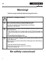
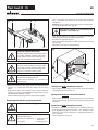
Betriebsanleitung Operating manual Mode d’emploi Gebruiksaanwijzing Plast Coat PC 25 PC 35 0348 870 03 / 2010 p. 2 p. 24 p. 48 p. 72 Plast Coat 25 · 35 GB Warning! Suction pumps develop high spraying pressures. Attention − Danger of injury! 1 Never reach into the spray jet with your fingers or hand! Never aim the spray lance at yourself or other persons! The materials sprayed cause chemical burns or irritations! Protect your skin and eyes! 2 Each time before starting up, follow the procedure below as specified in the Operating manual: 1.Only connect to the mains supply using a special distributing point, e.g. using a site distribution system with fault current protection with INF ≤ 30 mA. 2.Observe the permissible pressures. 3.Check all the connecting parts for leaks. 3 Instructions for regular cleaning and servicing of the machine must be strictly adhered to. Before starting any work on the machine and during breaks, follow the procedure below: 1.Note the setting time of the material. 2.Relieve the pressure in the spray lance and hose. 3.Switch the machine off. Be safety-conscious! 26 Plast Coat 25 · 35 GB Contents Contents 1 Safety requirements______________________ 28 2 Introduction to working with the mortar spraying machines PlastCoat 25 and 35_ __ 29 2.1 Operation of the mortar spraying machines PlastCoat 25 and 35 _ __________________________ 29 2.2 What materials can be sprayed?__________________ 29 3 Technical data PlastCoat 25 and 35_______ 29 4Equipment overview – mortar spraying machines PlastCoat 25 and 35_____________ 4.1 Control unit_ ________________________________ 4.1.1 Symbols on the changeover switch_______________ 4.2 Drive_ ______________________________________ 4.3 Receptacle_ _________________________________ Accessories for the receptacle_ __________________ 4.3.1 Sliding cover_ ________________________________ 4.3.2 Sack mangle_ ________________________________ 4.3.3 Container suction system_______________________ 4.4 Compressor (accessory) _______________________ 4.5 Mortar hose with electrical remote control _ _____ 4.6 Spray lance with automatic control _____________ 4.7 Spray lance without automatic control__________ 30 31 31 31 31 32 32 32 32 32 32 33 33 5 Transport_________________________________ 33 5.1 Transport using a crane_________________________ 33 6 Coating materials equipment table PlastCoat 25 and 35_ ___________________ 34/35 7 Placing into operation ________________ 36-38 8 General requirements for application technology_ _________________________________ 38 12 Servicing__________________________________ 43 Electrical equipment___________________________ 43 Long-term storage_ ___________________________ 43 13 Spare parts list – PlastCoat 25 and 35_____ 44 Spare parts illustration – PlastCoat 25 and 35_ ______________________ 97 14 Spare parts list – Spray lance with automatic control_______________________ 19 Spare parts illustration – Spray lance with automatic control____________ 97 15 Spare parts list – Spray lance without automatic control______________ 19 Spare parts illustration – Spray lance without automatic control________ 97 16 Spare parts list and spare parts illustration – Compressor V 400__________ 20 17 Spare parts list and spare parts illustration – Container suction system_ 21 18 Accessories – PlastCoat 25 and 35 _________ 22 Accessories illustration – PlastCoat 25 and 35 ____________________ 98/99 WAGNER-customer service depots___________________ 112 Important notes on product liability__________________ 103 Warranty_____________________________________103/104 Declaration of conformity_______________________ 109 9 Fitting accessories _ ___________________ 39/40 9.1 Compressor__________________________________ 39 9.2 Sack mangle_ ________________________________ 39 Using coating materials in sacks__________________ 40 9.3 Container suction system_______________________ 40 10 10.1 10.2 10.3 Placing out of operation and cleaning_ _ Cleaning the mortar hose _ _____________________ Cleaning device and changing pump jacket________ Cleaning spray lance___________________________ 40 40 41 41 11 Malfunction checklist_ _______________ 42/43 27 Plast Coat 25 · 35 GB Safety Requirements 1 Safety requirements Danger of injury from the screw conveyor. Only reach into the container with the mortar spraying machine switched off. Only switch on the mortar spraying machine with the safety grill inserted. The safety grill must be inserted for all day to day working and cleaning activities All local safety regulations in force must be observed. For safe operation of the mortar spraying machines, always comply with the following specific instructions: 1.Use of the mortar spraying machines The mortar spraying machines PlastCoat 25 and 35 are designed only for the spraying of the materials described on page 27. Any other use is not permitted. The manufacturer cannot be held liable for any damage resulting from this. In such cases, the risk will be borne solely by the user. Intended use also includes compliance with the Operating manual and compliance with the inspection and servicing conditions. Always keep the Operating manual ready at hand at the machine location. 2.The mortar spraying machines PlastCoat 25 and 35 may only be operated with a pressure gauge. Only the mortar hose prescribed by the manufacturer may be used. 3. Only use identified mortar hoses with an operating pressure of at least 40 bar. 4. Personnel safety Always wear protective goggles, protective clothing and gloves and, if necessary, skin barrier cream and breathing equipment, to protect your eyes, skin and respiratory system. Never uncouple mortar hose while it is still under pressure. Note pressure gauge! Wear protective goggles! Never aim spray lance at any person! 5. Breathing masks Breathing masks must be provided for the operator to protect against mineral dust. 6. Only connect to the mains supply using a special distributing point, e.g. using site distribution system with fault current protection with INF ≤ 30 mA. 7.The master switch has an EMERGENCY OFF function. 28 8. Prevent the socket for the remote control on the control unit from getting dirty. Always leave the coupler plug of the remote control line on the mortar hose screwed complete into the control unit. 9. Cleaning and servicing Never uncouple mortar hoses under pressure. Before uncoupling, check pressure on the pressure gauge. Turn off the mortar spraying machine for cleaning and maintenance work. Pull out mains plug and ensure that it cannot be plugged back in unintentionally. Do not spray the motor or control unit of the mortar spraying machine with water jet, high-pressure or steam cleaning equipment. Water could penetrate the machine and cause a short-circuit. 10.Electrical equipment Work on the machine’s electrical equipment may be carried out only by a qualified electrician. The electrical equipment must be inspected regularly. Defects such as loose connections or scorched cables must be remedied immediately. 11.Keep the labels on the mortar spraying machine clean and legible. 12. Positioning on uneven ground The front of the mortar spraying machine must point upwards to avoid that the machine slips away. Plast Coat 25 · 35 GB Introduction to working with the motar spraying Machines/ Technical Data 2 Introduction to working with the mortar spraying machines PlastCoat 25 and 35 The mortar spraying machines can be combined with continuous flow, gravitation compulsory or pan mixers for the processing of mineral coating materials. The container suction system (accessory) can be used to suck directly from a container. All coating materials should be suitable for applying using machines. See product data sheet for the coating material to be used. Only use other materials after prior consultation with the manufacturer or WAGNER application technology dept. 3 Technical data Voltage: 2.1 Operation of the mortar spraying machines PlastCoat 25 and 35 The coating materials are supplied to the machine by means of the receptacle. The spiral conveyor feeds the coating material into an eccentric screw pump. This pump generates the pressure required for the transport through the mortar hose. The compressed air necessary for the atomizing of the material is fed into the spray lance. The mortar spraying machine can be switched on and off using the electrical remote control. The continuously adjustable feed rate of the coating material can be used to create a soft, even spraying pattern. What materials can be sprayed? • Heat insulating composite system adhesive (mineral and synthetic resin systems) • Synthetic resin plasters up to grain size of 5 mm • Silicate plasters up to grain size 5 • Silicate resin plasters up to grain size 5 • Mineral final coat plaster up to grain size 5 • Light plaster systems up to grain size 5 • Scraped rendering up to grain size 5 • Insulation plaster • Renovating plaster • Foam mortar coating • Quartz plastic • Roof coatings • Flameproof coatings • Mineral sealing slurries • Bitumen emulsions • Reinforcing filler • Liquid wood chip • Frame sealing mortar • Synthetic resin rendering base • Primer • Filling paints, incl. fiber containing • Elastic coatings • Acoustic plaster, synthetic resin bonded • Filler, synthetic resin bonded • Concrete trowel PlastCoat 35 230 V ~, 50 Hz 400 V, 50 Hz V3 ~ Fuse protection: 16 A slow-blow Device mains cable 6 m long: 3 x 2.5 mm2 5 x 1.5 mm2 Motor output P1: 2.2 kW 3.6 kW Max. feed rate (water): Pump yellow: Pump brown: Pump green: 10 l/min 15 l/min 20 l/min 15 l/min 20 l/min 25 l/min Max. operating pressure: 40 bar Max. grain size: K5 mm Measurements L x W x H: 1200 x 520 x 660 mm Receptacle capacity: Weight: 2.2 PlastCoat 25 60 l 85 kg 87 kg Tire pressure, max.: 2 bar Protective system: IP 54 Max. sound pressure level: Atomization air connection: Max. atomization air pressure: Required volume of compressed air, min: Texture nozzle: Mortar hose: 77 dB (A)* Rapid action coupling DN 7 mm 10 bar 220 l/min 8 mm (standard) DN 27 mm, 10 m (standard) * Measuring point: At a distance of 1m to the side of the unit and at a height of 1.60 m above floor, reverberant floor. 29 Plast Coat 25 · 35 GB Equipment Overview 4 1 2 3 4 5 6 7 8 9 10 Equipment overview – mortar spraying machines PlastCoat 25 and 35 Control unit Receptacle Screw conveyor Pump jacket – pump screw Pressure gauge Outlet unit Compressed air connection Mortar hose, assy. Texture nozzle Spray lance with automatic control 11 Switch sleeve, for switching the mortar spraying machine on and off using remote control 12 Spray lance without automatic control 13 Remote control switch, for switching of the mortar spraying machine on and off using remote control 14 Electric motor with transmission 15 Bar for wrapping the mains cable 16 Connection for remote control 17 Safety guard 1 2 3 17 16 15 4 5 14 6 13 30 12 9 11 10 9 8 7 Plast Coat 25 · 35 GB Control unit 4.1 1 2 3 4 5 6 4.1.1 Control unit Master switch 0–1 Indicator lamp Feed rate regulator 0–10 Changeover switch Mains cable Connection for remote control Symbols on the changeover switch (fig. 4) 1 Releasing the pressure or removing the pump jacket. Pump runs in reverse direction. 2 “0” drive is switched off. 3 “AUTO” remote control using the spray lance. 4 Spraying or pulling on the pump jacket. Pump runs in the forwards direction. 2 6 3 O AUTO. 1 4 2 3 1 4 5 The mortar spraying machine can be switched on using the master switch (1, fig. 3). The indicator lamp (2) shows that the machine is ready for operation. The feed rate can be continuously adjusted by means of the feed rate switch (3). 4.2 Drive If overloading occurs then the mortar spraying machine switches off. Turn master switch (1, fig. 3) and changeover switch (4, fig. 3) to “0”. Wait at least 10 seconds and then turn the mortar spraying machine back on. 4.3 Receptacle (fig. 5) 1 receptacle made of high-grade steel with grating. Contents: 60 liter 1 31 Plast Coat 25 · 35 GB Accessories for the receptacle Accessories for the receptacle 4.5 4.3.1 1 2 3 4 5 6 7 Sliding cover Prevents contamination getting into the coating material. Extends the hardening time of the coating material, particularly with direct sunlight. 4.3.2 Sack mangle For using coating material in sacks, a sack mangle can be placed on the sliding cover. 4.3.3 Mortar hose with electrical remote control (fig. 7) Material connection – mortar spraying machine Remote control connection – mortar spraying machine Atomization air connection – compressed air supply Material connection – spray lance Mortar hose Atomization air connection – spray lance Remote control connection – spray lance or remote control switch 1 2 Container suction system For sucking up coating material from a container, an external container can be employed instead of the receptacle. 4.4 Compressor (accessory) V 400 suction volume 360 l/min (fig. 6) 1 Compressor holder 2 Compressed air connection Note: Only operate the compressor according to the operating manual included. 2 1 32 7 6 5 4 3 Plast Coat 25 · 35 GB Transport 4.6 Spray lance with automatic control (fig. 8) 1 Material connection 2 Switch sleeve, switching the mortar spraying machine on and off using remote control 3 Texture nozzle 4 Air tap 5 Material tap 6 Remote control connection 7 Atomization air connection 1 5 Transport • Moving the mortar spraying machine on its wheels: Hold the fold-out handles (1, fig. 10), lift and move. • Carrying the mortar spraying machine: Hold the fold-out handles (1) and front bar (2) and lift. Transport using a crane For attaching points for the straps or rope (not wire cable) see figure 10. 3 6 5 5.1 2 7 Various different texture nozzle can be fitted to the spray lance, see accessories page 48, item 1. The size of the nozzle depends on the grain size of the coating material and the required spraying pattern. 4 Various different texture nozzles can be fitted to the spray lance, see accessories page 48, item 1. The size of the nozzle depends on the grain size of the coating material and the required spraying pattern. 4.7 1 2 3 4 5 Spray lance without automatic control (fig. 9) 2 Atomization air connection Air tap Texture nozzle Material tap Material connection 1 1 2 5 4 3 33 Plast Coat 25 · 35 GB Coating materials equipment table PlastCoat 35, 400 V, 50 Hz, V3~ ✶ ✶ ✶ ✶ ✶ ✶ ✶ ✶ ✶ ✶ 0348 946 Mortar hose DN 35 – 13,3 m x piece 0348 912 Mortar hose DN 27 – 10 m x piece 4 3 0348 909 Mortar hose DN 19 – 10 m x piece 1 1 0342 255 Mortar hose DN 19 – 2 m 0348 241 0342 200 Spray lance with automatic control Spray lance without automatic control ● 0348 960 Ceiling spray lance with automatic control 0342 912 Rendering lance 0342 246 Application gun Mortar hoses Spray lances and nozzles Pumps Accessories 1 1 4 3 2 1 1 Silicon resin plaster up to G 5 0348 . . . Silicate plaster up to G 5 ✶ KH scraped rendering up to G 5 ✶ KH groove plaster up to G 5 ✶ KH reinforcing filler ✶ KH rolling and filling plaster Foam mortar coating PlastCoat 25, 230 V~, 50 Hz Quartz-containing mineral paints Wood chip paint 0348 . . . KH-smooth and texture filler Description Caption: up to 30 m delivery radius ● necessary accessory ✶ up to 50 m delivery radius recommended accessory RW Stirring apparatus T25 K Continuous mixer ZM Compulsory mixer KH-base plastic/quarz plastic Part No. PlastCoat 25 and PlastCoat 35 1 1 1 1 1 3 3 3 3 ● ● ● ● 7 7 7 4 4 2 1 1 1 ● ● ● ● ● ● ● 200 U 0268 779 Texture nozzle 4 0348 915 Texture nozzle 5 5 5 0268 780 Texture nozzle 6 6 6 0348 916 Texture nozzle 7 0268 781 Texture nozzle 8 0348 917 Texture nozzle 9 0268 782 Texture nozzle 10 10 10 10 10 0342 327 Texture nozzle 12 12 12 12 12 0268 905 Texture nozzle set 4 6 8 0268 726 Rendering nozzle set 14 16 18 0348 315 0348 316 Pump jacket yellow (standard) Pump screw yellow (standard) 0348 925 0348 926 Pump jacket brown (accessory) Pump screw brown (accessory) 0348 927 0348 928 Pump jacket green, retightenable (accessory) Pump screw green (accessory) 0342 231 Compressor V 400, suction volume 360 l/min, 230 V~, 50 Hz 0348 963 Sack mangle (Sliding cover 0348 962 necessary) 0348 907 Container suction system 0343 002 Continuous mixer Wagner T 25 K Accessoires illustration, see page 99/100. 34 Synthetic resin based systems Coating materials equipment table KH-coating plaster/concrete contact 6 4 4 5 5 5 6 6 6 6 7 7 7 7 7 7 8 8 8 8 8 8 8 8 8 9 9 9 9 9 6 10 ● ● ● ● ● ● ● ● ● ● ● ● ● ● ● ● 500l ● 500l ● ● ● ● ● ● RW RW RW RW RW RW RW RW RW RW RW RW PCC renovating mortar up to G 4 Quartz-containing elastic slurries ✶ ✶ ✶ ✶ ✶ ✶ ✶ ✶ ✶ ✶ ✶ 2 2 2 2 2 1 1 1 1 2 2 2 2 2 2 2 2 2 2 1 3 3 1 1 ● ● ● ● ● ● ● ● ● ● ● ● ● ● ● ● ● ● ● ● ● ● ● 16 ● ● 16 ● ● ● ● 2 3 ● 16 ● 500 l 1 ● 18 ● ● 3 2 ● ● 18 ● ● ● ● 3 3 1 1 ● ● 8 8 8 8 8 9 9 9 9 9 9 10 10 10 10 10 10 12 12 14 ● ● ● ● ● T25K T25K T25K T25K T25K T25K T25K T25K T25K T25K T25K T25K T25K T25K ZM RW ● 4 5 5 6 6 6 6 7 7 7 7 8 8 12 ● ● ● ● ● ZM RW 5 6 7 8 ● 500l Roof coating Flameproof coatings Mineral special scraped rendering Flame protection mortar Slot wall mortar Acoustic plaster Renovating plaster Insulating plaster Lime cement base plaster Cement pedestal plaster Lime internal plaster Light texture plaster Light first coat plaster Groove plaster up to G 5 Special applications Information on requestTest may be necessary ● Bitumen sealing 2 Information on requestTest may be necessary 1 Information on requestTest may be necessary PCC-seal/elastic slurries Reinforcing fibre filler PCC fine/cavity filler WDVS adhesive/filler Plast Coat 25 · 35 GB Coating materials equipment table Mineral plaster systems For coating materials from the container RW Only use other coating materials after consulting WAGNER application technology department. 35 Plast Coat 25 · 35 GB Placing into operation 7 Placing into operation Connecting spray lance with automatic system Installation location Position mortar spraying machine in a level position to prevent it from sliding away. Compressor (accessory) Attach compressor holder to the mortar spraying machine. Place compressor onto holder and secure with screws. Connect compressor to power supply. Connecting mortar hose • Check that the outlet unit (1, fig. 11) is seated firmly. If necessary tighten star grips (2) by hand. • Connect mortar hose (3) and secure with tension levers (4). • Screw remote control to connection (5) on the control unit. • Connect atomization air connection (6) on mortar hose to the compressed air supply or compressor (accessory). • Assemble texture nozzle (1, fig. 12) on the spray lance with cone in the direction of the spraying head. The nozzle size should be at least three times the grain size, e.g., grain size synthetic resin plaster –> 3 mm nozzle size –> 10 mm • Connect spray lance (2) and secure with tension levers (3). • Close material tap (4). • Screw coupling plug (5) for remote control to the control cable of the mortar hose. • Connect atomization air connection (6) to the air hose of the mortar hose. 3 2 1 5 6 5 4 Connecting spray lance without automatic system 2 1 4 6 36 3 • Fasten remote control switch (1, fig. 13) with the two O-rings (2) to the mortar hose. • Screw coupling plug (3) for remote control on the control cable of the mortar hose. • Assemble texture nozzle (4) on the spray lance with cone in the direction of the spraying head. The nozzle size should be at least three times the grain size e.g., grain size synthetic resin plaster –> 3 mm nozzle size –> 10 mm • Connect spray lance (5) and secure with tension levers (6). • Close material tap (7). • Connect atomization air connection (8) to the air hose of the mortar hose. Plast Coat 25 · 35 GB Placing into operation 8 5 • Fill 2–3 l synthetic resin dispersion or cellulose paste into the receptacle. • Caution: set changeover switch (4, fig. 14) to „0“ before turning on the master switch (1, fig. 14). 7 The pump is switched on, even if the feed rate regulator is at position „0“. 3 2 1 6 4 • Turn master switch (1, fig. 14) to „1“, the indicator lamp will show that the machine is ready for operation. • Set feed rate regulator (3) to „5“. • Turn changeover switch (4) to „AUTO“ (remote control using spray lance). • Hold spray lance over an empty bucket. Extension cable PlastCoat 25 The cross section of the cable must be min. 3 x 2.5 mm. Unwind extension cable completely. Make sure that the couplings and plugs are in complete working order. 2 Extension cable PlastCoat 35 The cross section of the cable must be min. 5 x 2.5 mm. Unwind extension cable completely. Make sure that the couplings and plugs are in complete working order. Arrange the mains cable so that there is no danger of it being tripped over. Protect against damage, e.g., caused by it being run over. • Before connecting to the mains make sure that the mains voltage is in accordance with the details on the rating plate. • Only connect to the mains supply using a special distributing point, e.g. using a site distribution system with fault current protection with INF ≤ 30 mA. • Connect mortar spraying machine to the mains supply. Preparing the mortar spraying machine Only work with the safety grill inserted! Recommended lubricant for the mortar hose Water is not a satisfactory lubricant. Danger of blockages! Synthetic resin products –> synthetic resin dispersion PCC systems –> cellulose paste 3 1 4 Spray lance with automatic control • Open material tap (3, fig. 15) on the spray lance. The mortar spraying machine will switch on. Spray lance without automatic control • Open material tap (3, fig. 16) on the spray lance. Press remote control switch (1, fig. 16). The mortar spraying machine will switch on. Spray lance with automatic control • When the synthetic resin dispersion or cellulose paste has been pumped into the mortar hose – turn off device, turn switching sleeve (1, fig. 15) by 90° in a clockwise direction as far as it will go. • Close material tap (3, fig. 15). 37 Plast Coat 25 · 35 GB General requirements for application technology Spray lance without automatic control • Close air tap (2, fig. 15). • When the synthetic resin dispersion or cellulose paste has been pumped into the mortar hose – turn off device with remote control switch (1, fig. 16). • Close material tap (3, fig. 16). • Check viscosity of the coating material. • Fill coating material into the receptacle. With mineral coating materials only fill the receptacle to half full. Spray lance without automatic control • Press remote control switch (1, fig. 16) on mortarhose. • Wait 3–5 seconds. • Close material tap (3, fig. 16). Noncompliance with the above instructions will result in additional wear of the material tap. Spray lance with automatic control • Open material tap (3, fig. 15). • The coating material will be pumped into the mortar hose. Spray lance without automatic control • Open material tap (3, fig. 16). • Turn on device with remote control switch (1, fig. 16). • Coating material will be pumped into the mortar hose. • Pump synthetic resin dispersion or cellulose paste from the mortar hose into a bucket. • As soon as coating material starts coming out of the spray lance – turn off device using remote control and close material tap on the spray lance. • Hold spray lance over the receptacle. • Open material tap (3, fig. 15 and 16) and turn on device using remote control. • Set the feed rate regulator (3, fig. 3, page 31) to the required feed rate. • Turn off device using remote control and close material tap (3, fig. 15 and 16). • Fasten mortar hose using hose holder to the frame (each connecting hose separately). • Close air tap (2, fig. 16). Spray lance with automatic control (fig. 15) 1 3 2 Spray lance without automatic control (fig. 16) Do not kink the mortar hose! Protect it against damage e.g., resulting from it being run over or from sharp objects. 2 Starting the spraying procedure • Open air tap (2, fig. 16 and 17) and material tap (3, fig. 15 and 16) on the spray lance. Spray lance without automatic control Turn device on using remote control switch (1, fig. 16). End of the spraying procedure Spray lance with automatic control • Turn switching sleeve (1, fig. 15) 90° clockwise as far as it will go. • Wait 3–5 seconds. • Close material tap (3, fig. 15). Noncompliance with the above instructions will result in additional wear of the material tap. 38 1 8 3 General requirements for application technology Spraying technique Guide the spray lance at a uniform distance of 30 – 60 cm from the object when spraying. If you do not do this, you will not achieve a regular spray pattern. The spray pattern is dependent upon the type of material, material consistency, tip size, Plast Coat 25 · 35 GB Fitting accessories material delivery rate and air delivery rate. fine texture ––> larger air delivery rate coarse texture ––> low air delivery rate Higher material delivery rate ––> higher air delivery rate We recommend that you test the required texture on a sample surface. To improve the „feathering effect“ in order to allow easier overlap, choose an appropriate distance between the spray lance and the object surface. The spray margin should „feather out“ to allow easier overlapping. Considerably less spray mist is produced if the spray lance is always guided at 90° parallel to the spray surface. Note: Sharp-edged grains and pigments will increase wear on the pump, hose, material ball valve and tip. 9 Fitting accessories 9.1 Compressor V 400 suction volume 360 l/min • Attach compressor holder (item 1, fig. 17) and secure with star grip (2). • Place compressor onto holder. Slide retaining plate (3) over the compressor base. • Secure the compressor with star grips (4). 9.2 Sack mangle Safety note Danger of crushing. Do not pace hands under the roller. Technical data Roller length: 465 mm Roller diameter: 66 mm Weight: 6.7 kg Putting sack mangle into operation • Connect crank handle (1, fig. 18) and secure with linch pin. • Insert sack mangle and sliding cover (2, accessory). • Screw out star grips (3) about 2 cm. • Place sack mangle and crank handle (1) on the sliding cover to the right from the front. Move guide rollers (4) over stop pins on the underside of the sliding cover. • Adjust pressure force of the roller (5). Turn the star grips (3) to the right until they will go no further. • Turn crank and move sack mangle to the rear as far as it will go. 2 3 2 5 1 4 3 4 1 39 Plast Coat 25 · 35 GB Placing out of operation and cleaning Using coating materials in sacks • Pull sliding cover back about 15 cm. • Place sack on the sliding cover in such a way that the top faces the front end of the sliding cover. • Cut sack open. • Allow the coating material to flow into the receptacle. • Move sack mangle forwards over the sack by turning the crank handle until the guide rollers reach the stop pins. • To ease pressing – move sack mangle to frame of sack mangle with your left hand. • Strip remaining coating material from sack opening with a spatula. 9.3 1 2 5 Container suction system • Turn off device at master switch. • Pull out mains plug from the socket and ensure that it cannot be plugged back in unintentionally. • Unscrew the hexagon nuts (2) on the receptacle (1, Fig. 19), remove washers. • Remove receptacle. • Attach container connection (3) to the base of the receptacle. Mount disks and secure with hexagon nuts (2). • Connect suction hose (5) to container connection (3). Alternatively, connect connecting bridge (6) to the container connection (3) and connect suction hose (5) to connecting bridge. • Fill suction hose with water and connect to the container. • Turn on mortar spraying machine. Note: All connections must be sealed air tight so that a vacuum can be produced. Place a small amount of machine lubricant onto the rubber seals of the connections in order to allow for the easy opening and closing of the connectors. 6 3 2 10 Placing out of operation and cleaning Do not spray the motor or control unit of the mortar spraying machine with water jet, high-pressure or steam cleaning equipment. Water could penetrate the machine and cause a short-circuit. 10.1 Cleaning the mortar hose • Pump until receptacle is empty. When operating using the container suction system, remove suction hose from the container. Important: Do not let the mortar spray machine run dry. • Remove texture nozzle from spray lance and clean. The mortar hose must be without pressure. If necessary, turn changeover switch briefly to (backwards). Note the pressure gauge ––> 0 bar. Wear protective goggles. 40 Plast Coat 25 · 35 GB Placing out of operation and cleaning • Disconnect the mortar hose from the outlet section. • Insert cleaning ball in the mortar hose. Re-connect the mortar hose. • Fill water into receptacle. When operating using the container suction system, immerse suction hose into receptacle with water. Turn on mortar spraying machine. • After a few seconds the cleaning ball will come out of the spray lance. • Repeat cleaning procedure 3–4 times, depending on the coating material used. There is a further possibility for cleaning using the cleaning adapter. This cleaning adapter can be connected to a water hose or tap with a claw coupling. Place cleaning ball in the mortar hose. Couple mortar hose to the cleaning adapter and rinse through with water. 10.2 • Unscrew and remove container connection from the receptacle lower section. • Clean receptacle lower section, container connection and suction hose with a water jet and, if necessary, using a suitable brush. • Clean pump screw and pump jacket thoroughly with water. • Clean outlet unit (2) inside using a bottle brush. • Keep threads for the star grips clean and grease. Cleaning device and changing pump jacket Never remove the safety grill for any cleaning work! Disassembly • Lubricate pump. • • • • Turn changeover switch to (backwards). Spray pump antiseize or a little dishwashing liquid into the outlet unit (2, fig. 22) or place a little dishwashing liquid into the receptacle and pump through the pump. Turn changeover switch to „0“. Unscrew star grips (1, fig. 20). Remove outlet unit (2) towards the front. Set feed rate to „3“. • Turn changeover switch to 3 4 1 2 Pump jacket assembly Important: Spray pump screw and pump jacket with pump antiseize or wet with dishwashing liquid. • Turn changeover switch to (forwards). (backwards). Danger of crushing! Danger of crushing! • Pump jacket (3) will disconnect from pump screw. • Set changeover switch to „0“. • Clean receptacle and receptacle lower section with a water jet. When operating using the container suction system, turn off device using master switch. Remove the mains plug from the socket and ensure that it cannot be replaced unintentionally. • Place pump jacket (3, fig. 20) onto pump screw. Ensure that the ledge of the pump jacket (3) is properly slid into the rectangular recess of the pump trigger (4). • Pump jacket pulls itself onto the pump screw. • Set changeover switch to “0”. • Assemble outlet unit. 10.3 Cleaning spray lance • Clean texture nozzle. • Clean air holes in the texture nozzle with a cleaning needle. • Clean the inside of the spray lance with a bottle brush. 41 Plast Coat 25 · 35 GB Malfunction checklist 11 Malfunction checklist Fault Possible cause Motar spraying machine does not start The mortar spraying machine has been Set master switch and changeover switch to „0“. overloaded. Turn mortar spraying machine back on after about 10 sec. Caution: set changeover switch to „0“ before turning on master switch. Mortar spraying machine cannot turn pump screw. Pump screw is stuck in pump jacket. Mortar spraying machine cannot be switched on/off by means of the remote control. Remote control not on. Set changeover switch to “AUTO”. Remote control line not connected or defect. Connect remote control, check connections, check remote control line for damage. Mortar spraying machine builds up pressure in the mortar hose. However, no coating material comes out of the spray lance. Coating material “blockages” in mortar hose. Motor hose not pre-rinsed with synthetic resin dispersion or cellulose paste. Find blockage by feeling the mortar hose. Remove pressure from mortar hose set changeover switch to (backwards). Pump was not lubricated with pump antiseize. Remedy Set delivery rate switch to “0”. Set changeover switch to (forward). As soon as the pump screw rotates at a constant speed, slowly set the delivery rate switch to the desired delivery rate. Pump coating material back into receptacle. Mortar hose must be without pressure. Observe pressure gauge ––> 0 bar. Wear protective goggles. Disconnect mortar hose – bend the blocked area by hand. Rinse mortar hose with a water hose. When the blockage has been removed, fill the mortar hose with synthetic resin dispersion or cellulose paste. Re-connect mortar hose. The spray jet stops while spraying, ”spluttering” occurs. No coating material in receptacle. Pump has sucked up air. Fill with coating material and pump in circulation until coating material is free of bubbles. Caution: Do not allow the pump to run dry. The pump will heat up, thus danger of ”blockage”. Refill with coating material. Coating material is not sliding down in the receptacle. In all cases turn off mortar spraying machine (see safety requirements) – then push down the coating material. Coating material suddenly stops Blockage in texture nozzle due to imcoming out while spraying. purities in the coating material or too large grain size. Turn off mortar spraying machine. Close the material tap on the spray lance. Remove texture nozzle and clean. If necessary, use larger texture nozzle. Rule of thumb: Grain size x 3 ––> Nozzle size. No clean, even spraying pattern. Air channels in the texture nozzle are Turn off mortar spraying machine. partially blocked with coating material. Close material tap on spray lance. Remove texture nozzle. Clean air channels in the texture nozzle. 42 Plast Coat 25 · 35 GB Malfunction checklist Fault Possible cause Remedy Pressure on the pressure gauge increases to over 40 bar. Viscosity of the coating material too high. Dilute the coating material. Mortar hose diameter too narrow. Use a mortar hose with a larger diameter. Mortar spraying machine does not transport sufficient coating material. Mortar hose too long. Use shorter mortar hose. Flow speed selected too low. Set feed rate to a higher setting. Mortar hose diameter too narrow. Use a mortar hose with a larger diameter. Pump jacket worn. Install new pump jacket and, if necessary, new pump screw. Caution: Spray with pump antiseize. Viscosity of the coating material too high. Dilute coating material. Texture nozzle too small. Select a larger texture nozzle. If none of the above-mentioned possible causes was the reason for malfunction, there must be a defect which will be repaired by the WAGNER after-sales service. 12 Servicing • Keep the threads for the star grips clean and oiled. • Spray pump screw and pump jacket with pump antiseize. • Geared-motor is maintenance-free. Electrical equipment Check lines and plug connections. Rectify faults such as loose connections, smoldered wires or dirty or damp plug connections immediately. Work and repairs on the electrical equipment may be carried out only by a qualified electrician even if the product is accompanied with operating instructions. We are unable to assume liability for the consequences of incorrect installation. Long-term storage If it is intended to store the machine for a long period, it must be thoroughly cleaned and protected against corrosion beforehand. 43 44 9982 820 9982 823 0348 230 ------------- 9900 204 9920 102 9900 125 0348 334 9972 331 0348 400 9971 171 9930 913 0348 324 9921 518 0348 313 9922 746 0348 245 9900 511 0348 307 9900 109 0348 396 ------------- 9910 107 2311 356 0348 306 9910 208 9900 118 2 3 4 5 6 7 9 10 11 12 14 15 16 17 18 19 21 22 23 24 25 26 27 30 31 9900 118 9910 208 0348 306 2311 356 9910 107 ------------0348 397 9900 109 0348 307 9900 511 0348 245 9922 746 0348 313 9921 518 0348 324 9930 913 9971 171 0348 400 9972 331 0348 334 9900 125 9920 102 9900 204 ------------0348 231 9982 823 9982 820 Hexagon screw M 8 x 30 DIN 933 Hexagon nut M 8 DIN 985 Receptacle lower part Grating Hexagon nut M8 DIN 934 Type plate PlastCoat 25 Type plate PlastCoat 35 Hexagon screw M 8 x 25 DIN 933 Receptacle Countersunk screw Feed screw Snap ring A 45 Carrier bush Lock washer B12 DIN 127 Screw Straight pin 8 x 40 O-Ring 90 x 3,5 Intermediate flange Grooved ring 32 x 50 x 10 Supporting ring Hexagon screw M 8 x 50 DIN 933 Washer A 8,4 DIN 125 Hexagon screw M 8 x 35 DIN 931 (2) Transmission motor 230 V~, 50 Hz Transmission motor 400 V, 50 Hz, V3~ Adapter Cable screw connection Motor cable 0348 363 1 0348 363 Part No. Part No. Designation PlastCoat 25 PlastCoat 35 0342 321 0348 233 35 36 9982 822 9951 063 9951 078 52 53 ------------- 0348 422 0348 347 9910 204 9920 103 0348 318 9990 863 9900 317 0348 419 9994 902 0348 349 9991 947 9991 946 9970 109 51 50 49 48 47 46 45 44 43 42 41 40 39 38 9990 618 9990 368 34 37 0348 315 33 9951 078 9951 063 9982 822 0348 424 ------------- 0348 347 9910 204 9920 103 0348 318 9990 863 9900 317 0348 419 9994 902 0348 349 9991 947 9991 946 9970 109 9990 618 0348 233 0342 321 9990 368 0348 315 Hexagon nut Hexagon nut Cable screw connection Device mains connection H07 RN-F3G2,5 – 6 m Device mains connection H07 RN-F5G1,5 – 6 m Drawbar pipe left Hexagon nut M 6 DIN 985 Washer A 6,4 DIN 125 Drawbar tube right Pipe end cap Cheese head screw M 8 x 50 DIN 912 Trolley frame Wheel cap Wheel Protective cap Pressure gauge Sealing ring Coupling Outlet unit Adapter fix-nipple V 35-M 27 Star grip M 16 Pump jacket yellow W 10/3 (standard) Pump screw yellow W 10/3 (standard) 0348 316 32 0348 316 Part No. Part No. Designation PlastCoat 25 PlastCoat 35 Item Spare parts list PlastCoat 25 and 35 (Spare parts illustration, see page 97) Item 13 GB Plast Coat 25 · 35 Spare parts list PlastCoat 25 and 35 Plast Coat 25 · 35 GB Spare parts list – Spray lance 14 Spare parts list – Spray lance with automatic control (Spare parts illustration, see page 98) Part No. Spray lance (ceiling spray lance) 100 mm long 800 mm lang Designation Item Part No. Spray lance 0348 241 Item Part No. Spray lance 0348 923 ------------- 1 9910 208 9910 208 2 3 4 5 9920 102 0348 243 3051 679 0348 354 0348 921 0348 942 0348 355 0268 779 0348 915 0268 780 0348 916 0268 781 9920 102 0348 243 3051 679 ------------0348 921 0348 942 0348 355 0268 779 0348 915 0268 780 0348 916 0268 781 0348 917 0268 782 0342 327 0348 917 0268 782 0342 327 Spray lance with automatic control Extension kit 500 mm long (material pipe and air pipe) Extension kit 800 mm long (material pipe and air pipe) Hexagon nut M8 DIN 985 Washer 8.4 DIN 433 Lever O-ring 35 x 2 Air pipe 100 mm long Air pipe 800 mm long Air pipe 500 mm long Nozzle head Texture nozzle 4 Texture nozzle 5 Texture nozzle 6 Texture nozzle 7 Texture nozzle 8 (standard) Texture nozzle 9 Texture nozzle 10 Texture nozzle 12 0342 350 0342 350 Sealing washer 0348 904 6 7 8 15 0348 960 0348 904 0342 200 2 Designation 9 0342 351 0342 351 Union nut 10 0348 346 ------------ 0348 922 0348 922 0348 943 0348 943 11 9902 309 9902 309 12 13 14 15 16 17 18 19 0348 460 0348 216 0348 244 3105 540 0348 461 9920 104 0268 338 9983 237 0348 460 0348 216 0348 244 3105 540 0348 461 9920 104 0268 338 9983 237 9983 238 9983 238 20 0342 313 0342 313 21 22 9991 112 0268 604 9991 112 0268 604 Material pipe 100 mm long Material pipe 800 mm long Material pipe 500 mm long Pan head tapping screw 4.2 x 16 Cover Cable Connection sleeve O-ring 26 x 2 Stop Washer 4.3 Ball tap Double nipple 3/4 in – 1 in Double nipple 3/4 in – round thread 32 x 1/8 in Fix nipple connection V 27* Ball tap* Air hose* *Loctite 222 Spare parts list – Spray lance without automatic control (Spare parts illustration, see page 98) Item Part No. Designation Spray lance 100 mm long 1 Part No. Spray lance (ceiling spray lance) 100 mm long 800 mm lang 0268 779 0348 915 0268 780 0348 916 0268 781 0348 917 0268 782 0342 327 0342 350 Spray lance without automatic control Texture nozzle 4 Texture nozzle 5 Texture nozzle 6 Texture nozzle 7 Texture nozzle 8 (standard) Texture nozzle 9 Texture nozzle 10 Texture nozzle 12 Sealing washer Item Part No. Designation Spray lance 100 mm long 3 4 5 6 7 8 9 0342 351 0268 604 9991 112 0268 470 0342 469 9991 111 9983 237 9983 238 10 0342 313 Union nut Air hose* Ball tap* Nozzle head Material pipe* Ball tap Double nipple 3/4 in – 1 in Double nipple 3/4 in – round thread 32 x 1/8 in Fix nipple connection V 27 * * Loctite 222 45 Plast Coat 25 · 35 GB Spare parts list – Compressor 16 Spare parts list – Compressor V 400 Item Part No. Designation 1 0342 231 Compressor V 400, 230 V~, 50 Hz suction volume 360 l/min 2 9992 823 Rapid action coupling 3 0348 452 Retaining plate 4 0348 442 Compressor holder 5 9990 373 Star grip M 8 6 0348 957 Compressor holder 1 2 5 3 4 5 46 6 Plast Coat 25 · 35 GB Spare parts list – Container suction system 17 Spare parts list – Container suction system Item Part No. Designation 1 0348 907 Container suction system 2 9971 529 Seal 3 0342 205 Suction hose 4 0097 085 Coupling 5 0348 361 Connecting plate 6 0348 947 Connecting bridge 7 0097 105 Coupling 2 7 3 2 1 7 2 2 2 6 4 5 47 Plast Coat 25 · 35 GB Accessories PlastCoat 25 and 35 18 Accessories PlastCoat 25 and 35 (Accessories illustration, see page 99/100) Item Part No. Designation Item Part No. Designation 1 0268 779 Texture nozzle 4 14 9983 238 0348 915 Texture nozzle 5 Double nipple 3/4 in – round thread 32 x 1/8 in 0268 780 Texture nozzle 6 15 0342 200 0348 916 Texture nozzle 7 Spray lance 100 mm long without automatic control 0268 781 Texture nozzle 8 (standard) 16 0348 241 0348 917 Texture nozzle 9 Spray lance 100 mm long with automatic control 0268 782 Texture nozzle 10 17 0348 961 Angled spraying head 70° for spray lance with automatic control 0342 327 Texture nozzle 12 18 0348 904 0268 905 Texture nozzle 4, 6, 8, 10 2 0342 916 Cleaning needle Extension kit 500 mm long (material pipe and air pipe) for spray lance with automatic control 3 0342 330 Cleaning ball for DN 19 mm 0348 923 0342 331 Cleaning ball for DN 27 mm Extension kit 800 mm (material pipe and air pipe) for spray lance with automatic control 0342 332 Cleaning ball for DN 35 mm 19 0348 960 0342 329 Bottle brush for cleaning the inside of the outlet unit and spray lance Spray lance (ceiling spray lance) 800 mm long with automatic control 20 0342 285 Double spray lance 400 mm long with automatic control 4 5 9992 824 Pump antiseize 500 ml 6 0342 215 Hose holder 21 0342 912 Rendering lance 200 U 7 0342 241 Cleaning adapter M 27 – GK 22 0268 726 Rendering nozzle set 14, 16, 18 0348 948 Cleaning adapter M 35 – GK 23 0342 240 8 0348 920 0342 321 Adapter fix-nipple V 27 – M 35 Adapter fix-nipple V 35 – M 27 Texture spraying head for application gun 24 0342 246 9 0348 946 Mortar hose DN 35 – 13.3 m, connection V 35 – M 35 Application gun, connection V 27 for the application of heat insulation composite system adhesive 0348 912 Mortar hose DN 27 – 10 m, connection V 27 – M 27 25 0342 231 0348 930 Mortar hose DN 19 – 20 m, connection V 27 – round thread 32 x 1/8 in Compressor V 400, 230 V AC, 50Hz,suction volume 360 l/min without automatic switch-off 0342 906 0348 909 Mortar hose DN 19 – 10 m, connection V 27 – round thread 32 x 1/8 in Compressor V 400, 230 V~, 50 Hz, suction volume 360 l/min with automatic switch-off 26 0348 957 Compressor holder V 400 29 0348 316 0348 926 0348 928 Pump screw yellow (standard) Pump screw brown Pump screw green 30 0348 315 0348 925 Pump jacket yellow (standard) Pump jacket brown 31 0348 927 Pump jacket green, retightenable 32 0348 907 Container suction system 33 0348 962 Sliding cover for receptacle 0342 255 Mortar hose DN 19 – 2 m, connection V 27 – round thread 32 x 1/8 in 10 9952 672 Plug 11 0342 314 Seal fix-coupling M 27 9971 531 Seal fix-coupling M 35 12 9952 673 Coupling plug 13 0268 216 Pressure switch for remote control of spray lance without automatic control 48 34 0348 963 Sack mangle 35 0348 958 Accessory box with various accessories Plast Coat 25 · 35 GB 49 Plast Coat 25 · 35 d F 39 40 38 37 43 42 6 1 50 53 2 1 46 51 2 3 45 44 30 52 7 4 41 5 6 47 9 48 10 11 12 49 14 15 16 17 18 19 36 24 35 6 30 30 34 6 31 15 16 32 27 26 25 6 21 22 33 23 GB Spare parts illustration NL Afbeelding onderdelen Ersatzteilbild Eclaté 97 d Ersatzteilbild Spritzlanze mit Automatik GB Spare parts illustration – Spray lance with automatic control FEclaté lance de projection avec commande autom. NL Afbeelding onderdelen spuitlans met automaat 1 2 3 20 19 11 18 Plast Coat 25 · 35 17 4 5 4 16 6 7 8 15 14 13 12 22 11 10 21 d Ersatzteilbild Spritzlanze ohne Automatik GB Spare parts illustration – Spray lance without automatic control FEclaté lance de projection sans commande autom. NL Afbeelding onderdelen spuitlans zonder automaat 1 2 4 5 10 9 8 7 98 6 3 9 Plast Coat 25 · 35 1 d GB F NL 14 2 Zubehörbild Accessories illustration Illustration des accessoires Afbeelding met toebehoren 15 14 16 3 4 17 18 5 6 19 8 7 14 17 20 9 10 21 22 24 12 11 23 13 99 d GB F NL Plast Coat 25 · 35 Zubehörbild Accessories illustration Illustration des accessoires Afbeelding met toebehoren 25 26 33 29 30 31 34 35 32 100 Plast Coat 25 · 35 GB Testing of the unit Guarantee declaration For safety reasons, we would recommend having the device checked by an expert as required but at least every 12 months to ensure that it can continue to operate safely. In the case of unused devices, the check can be postponed until they are next started up. All (potentially deviating) national inspection and maintenance regulations must also be observed. If you have any questions, please contact the customer service team at Wagner. (Status 01.02.2009) NOTE ON DISPOSAL In observance of the European Directive 2002/96/EC on waste electrical and electronic equipment and implementation in accordance with national law, this product is not to be disposed of together with household waste material but must be recycled in an environmentally friendly way! Wagner or one of our dealers will take back your used Wagner waste electrical or electronic equipment and will dispose of it for you in an environmentally friendly way. Please ask your local Wagner service centre or dealer for details or contact us direct. Important notes on product liability As a result of an EC regulation being effective as from January 1, 1990, the manufacturer shall only be liable for his product if all parts come from him or are released by him, and if the devices are properly mounted and operated. If the user applies outside accessories and spare parts, the manufacturer´s liability can fully or partially be inapplicable; in extreme cases usage of the entire device can be prohibited by the competent authorities (employer´s liability insurance association and factory inspectorate division) Only the usage of original WAGNER accessories and spare parts guarantees that all safety regulations are observed. 1. Scope of guarantee All Wagner professional colour application devices (hereafter referred to as products) are carefully inspected, tested and are subject to strict checks under Wagner quality assurance. Wagner exclusively issues extended guarantees to commercial or professional users (hereafter referred to as “customer”) who have purchased the product in an authorised specialist shop, and which relate to the products listed for that customer on the Internet under www.wagner-group.com/profi-guarantee. The buyer’s claim for liability for defects from the purchase agreement with the seller as well as statutory rights are not impaired by this guarantee. We provide a guarantee in that we decide whether to replace or repair the product or individual parts, or take the device back and reimburse the purchase price. The costs for materials and working hours are our responsibility. Replaced products or parts become our property. 2. Guarantee period and registration The guarantee period amounts to 36 months. For industrial use or equal wear, such as shift operations in particular, or in the event of rentals it amounts to 12 months. Systems driven by petrol or air are also guaranteed for a 12 month period. The guarantee period begins with the day of delivery by the authorised specialist shop. The date on the original purchase document is authoritative. For all products bought in authorised specialist shops from 01.02.2009 the guarantee period is extended to 24 months providing the buyer of these devices registers in accordance with the following conditions within 4 weeks of the day of delivery by the authorised specialist shop. Registration can be completed on the Internet under www.wagner-group.com/profi-guarantee. The guarantee certificate is valid as confirmation, as is the original purchase document that carries the date of the purchase. Registration is only possible if the buyer is in agreement with having the data being stored that is entered during registration. When services are carried out under guarantee the guarantee period for the product is neither extended nor renewed. Once the guarantee period has expired, claims made against the guarantee or from the guarantee can no longer be enforced. 103 Plast Coat 25 · 35 GB 3. Handling 5. Additional regulations. If defects can be seen in the materials, processing or performance of the device during the guarantee period, guarantee claims must be made immediately, or at the latest within a period of 2 weeks. The authorised specialist shop that delivered the device is entitled to accept guarantee claims. Guarantee claims may also be made to the service centres named in our operating instructions. The product has to be sent without charge or presented together with the original purchase document that includes details of the purchase date and the name of the product. In order to claim for an extension to the guarantee, the guarantee certificate must be included. The costs as well as the risk of loss or damage to the product in transit or by the centre that accepts the guarantee claims or who delivers the repaired product, are the responsibility of the customer. The above guarantees apply exclusively to products that have been bought by authorised specialist shops in the EU, CIS, Australia and are used within the reference country. If the check shows that the case is not a guarantee case, repairs are carried out at the expense of the buyer. The above regulations manage the legal relationship to us concludingly. Additional claims, in particular for damages and losses of any type, which occur as a result of the product or its use, are excluded from the product liability act except with regard to the area of application. Claims for liability for defects to the specialist trader remain unaffected. German law applies to this guarantee. The contractual language is German. In the event that the meaning of the German and a foreign text of this guarantee deviate from one another, the meaning of the German text has priority. 4. Exclusion of guarantee J. Wagner GmbH Division Professional Finishing Otto Lilienthal Strasse 18 88677 Markdorf Federal Republic of Germany Guarantee claims cannot be considered --for parts that are subject to wear and tear due to use or other natural wear and tear, as well as defects in the product that are a result of natural wear and tear, or wear and tear due to use. This includes in particular cables, valves, packaging, jets, cylinders, pistons, means-carrying housing components, filters, pipes, seals, rotors, stators, etc. Damage due to wear and tear that is caused in particular by sanded coating materials, such as dispersions, plaster, putty, adhesives, glazes, quartz foundation. in the event of errors in devices that are due to non-compliance with the operating instructions, unsuitable or unprofessional use, incorrect assembly and/or commissioning by the buyer or by a third party, or utilisation other than is intended, abnormal ambient conditions, unsuitable coating materials, unsuitable operating conditions, operation with the incorrect mains voltage supply/frequency, over-operation or defective servicing or care and/or cleaning. for errors in the device that have been caused by using accessory parts, additional components or spare parts that are not original Wagner parts. for products to which modifications or additions have been carried out. for products where the serial number has been removed or is illegible for products to which attempts at repairs have been carried out by unauthorised persons. for products with slight deviations from the target properties, which are negligible with regard to the value and usability of the device. for products that have been partially or fully taken apart. -- ------- 104 Subject to modifications ∙ Printed in Germany Plast Coat 25 · 35 109