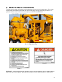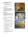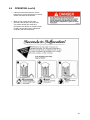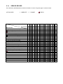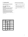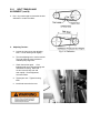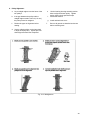
1
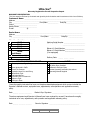
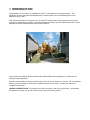
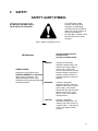
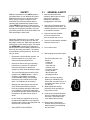
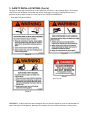
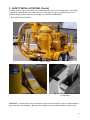
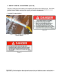
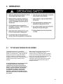
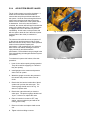
® ULTRA-VAC OPERATOR’S MANUAL Dear Customer, Thank you for choosing WALINGA TRANSPORTATION EQUIPMENT. For your convenience, should you require any information related to Parts, Service or Technical Engineering, please contact one of the following Walinga Personnel in Guelph at 1-888 925-4642 unless noted* TECHNICAL - ENGINEERING: Anthony Vis (ext: 239) [email protected] Ken Swaving *519 787-8227 (ext:100) [email protected] WARRANTY CLAIMS: For Customers in Canada: Gary Nijenhuis (ext:258) [email protected] For Customers in USA: Jonathan Medemblik * (800) 466-1197 (ext 8) [email protected] SERVICE MANAGER: Chris Ecclestone *(519) 787-8227 (ext:106) [email protected] ORIGINAL PARTS SALES: For Customers in Canada: Jack Lodder (ext: 224) [email protected] Parts Department Fax: (519) 824-0367 For Customers in USA: John VanMiddlekoop * (800) 466-1197 (ext 3) [email protected] ________________________________________ SERIAL NUMBER LOCATION Always give your dealer the Serial Number of your Walinga Ultra-Vac® when ordering parts or requesting service or other information. The Serial Number plates are located where indicated. Please mark the number in the space provided for easy reference. Machine Serial Number ______________________________________ Blower Serial Number ______________________________________ Airlock Serial Number ______________________________________ WALINGA INC. ULTRA-VAC WARRANTY ♦ For Farm Use Only , The Seller warrants to the Buyer that the Equipment manufactured by the Seller will be free from defect in material, workmanship and title for a period of one (1) year from the date of delivery to the Buyer. This warranty is subject to the following: ♦ For Commercial Use, The Seller warrants to the Buyer that the Equipment manufactured by the Seller will be free from defect in material, workmanship and title for a period of 90 days from the date of delivery to the Buyer. This warranty is subject to the following: a)The Seller’s obligation under said warranty shall be limited to repairing or replacing (at the Seller’s option) EXW (ExWorks) Guelph, Ontario, Canada, any part of the Equipment which, if properly installed, used and maintained, proves defective in material or workmanship, provided that notice of any such defect and satisfactory proof thereof is promptly given by the Buyer to the Seller; b)All costs of the installation or transportation pursuant to this warranty are for the account of the Buyer; c) The obligations set forth in this clause are conditional upon: i. Proper storage, installation (except where installation is supervised by or performed by the Seller), use, maintenance and compliance with any applicable recommendations of the Seller; and, ii. The Buyer promptly notifying the Seller of any defect and obtaining authorization prior to proceeding with repairs, and if required, promptly making the goods available for correction; d)In respect of any Equipment or part thereof supplied hereunder which are manufactured by others, the Seller gives no warranty whatsoever, and the warranty given by the manufacturer, if any, shall apply; e)The Seller shall not be liable for any cargo loss, loss of equipment, use or any other incidental or consequential damages resulting from any defective part or parts, the Seller’s liability and the Buyer’s exclusive remedy being expressly limited to the replacement of defective parts as provided herein; f) The warranty set out within this paragraph does not apply to: i. tires, accessories, and other items including the items, if any listed on the face hereof as “Buyers Specified Items”, manufactured by others and the Buyer shall rely solely on the warranty, if any, of the manufacturer of such tires, accessories and other items; nor ii. to any equipment, otherwise subject to this warranty, which shall have been repaired, modified or altered in any way by anyone other than the Seller or one of its duly authorized service representatives. g)With respect to used equipment sold hereunder, regardless of manufacture, the Seller makes no warranty whatever, and all warranties, express or implied are hereby excluded. With respect to such used equipment, the Buyer agrees to accept such used equipment on an “as is” basis. h) WARRANTY VOID IF NOT REGISTERED TABLE OF CONTENTS Serial Number Location......................................................................................................4 Warranty Registration Form & Inspection Report......................................................5 1 Introduction .....................................................................................................................8 2 Safety .............................................................................................................................9 2.1 2.2 2.3 2.4 2.5 2.6 2.7 2.8 2.9 General Safety .......................................................................................................10 Operating Safety ....................................................................................................11 Maintenance Safety ...............................................................................................12 Hydraulic Safety .....................................................................................................12 Storage Safety .......................................................................................................12 Transport Safety.....................................................................................................13 Tire Safety..............................................................................................................13 Safety Signs ...........................................................................................................13 Sign-Off Form.........................................................................................................14 3 Safety Decal Locations................................................................................................15 4 Operation ......................................................................................................................19 4.1 4.2 4.3 4.4 4.5 4.6 4.7 4.8 4.9 4.10 5 To The New Operator Or Owner ...........................................................................19 Machine Components ..........................................................................................20 Break-In................................................................................................................21 Pre-Operation Checklist .......................................................................................21 Controls................................................................................................................22 Attaching/Unhooking ............................................................................................23 Machine Preparation ............................................................................................24 Operating .............................................................................................................25 Transporting .........................................................................................................29 Storage ................................................................................................................31 Service And Maintenance..........................................................................................32 5.1.1 Fluids And Lubricants.......................................................................................32 5.1.2 Greasing...........................................................................................................32 5.2 Maintenance..............................................................................................................37 5.2.1 Belt Tension And Alignment .............................................................................37 5.2.2 Blower Oil Changing And Breather Cleaning ...................................................40 5.2.3 Airlock ..............................................................................................................42 5.2.4 Air System Relief Valves..................................................................................44 6 Trouble Shooting .......................................................................................................45 6.1 6.3 6.4 7 Mobile Transfer Unit............................................................................................45 Blower .................................................................................................................48 V-Belt Drive .........................................................................................................49 Specifications..............................................................................................................50 7.1 7.2 Mechanical ..........................................................................................................50 Bolt Torque..........................................................................................................51 7 1 INTRODUCTION ® Congratulations on your choice of a Walinga Ultra-Vac to complement your farming operation. This equipment has been designed and manufactured to meet the needs of the discriminating buyer for the efficient moving of grain. ® Safe, efficient and trouble free operation of your Ultra-Vac requires that you and anyone else who will be operating or maintaining the machine, read and understand the Safety, Operation, Maintenance and Trouble Shooting information contained within the Operator’s Manual. This manual covers Models 4510D, 5614D,6614D,7614D,8614D made by Walinga Inc. Differences are explained where appropriate. Keep this manual handy for frequent reference and to pass on to new operators or owners. Call your Walinga dealer if you need assistance, information or additional copies of the manual. Contact your dealer for a complete listing of parts. OPERATOR ORIENTATION - The directions left, right, front (hitch) and rear (receiver tank) , as mentioned throughout this manual, are as seen from the driver’s seat of the towing vehicle. 2 SAFETY SAFETY ALERT SYMBOL This Safety Alert symbol means ATTENTION! BECOME ALERT! YOUR SAFETY IS INVOLVED! The Safety Alert symbol identifies important safety messages on the Walinga Ultra-Vac® and in the manual. When you see this symbol, be alert to the possibility of personal injury or death. Follow the instructions in the safety message. Why is SAFETY important to you? Accidents Disable and Kill Accidents Cost Accidents Can Be Avoided 3 Big Reasons DANGER - Indicates an imminently hazardous situation that, if not avoided, will result in death or serious injury. This signal word is to be limited to the most extreme situations, typically for machine components that, for functional purposes, cannot be guarded. WARNING - Indicates a potentially hazardous situation, that if not avoided, could result in death or serious injury, and includes hazards that are exposed when guards are removed. It may also be used to alert against unsafe practices. CAUTION - Indicates a potentially hazardous situation that, if not avoided, may result in minor or moderate injury. It may also be used to alert against unsafe practices. SIGNAL WORDS: Note the use of the signal words DANGER, WARNING and CAUTION with the safety messages. The appropriate signal word for each message has been selected using the following guidelines: 9 SAFETY YOU are responsible for the SAFE operation and maintenance of your Walinga Ultra-Vac®. YOU must ensure that you and anyone else who is going to operate, maintain or work around the Ultra-Vac® be familiar with the operating and maintenance procedures and related SAFETY information contained in this manual. This manual will take you step-by-step through your working day and alerts you to all good safety practices that should be adhered to while operating the Ultra-Vac®. 2.1 GENERAL SAFETY 1. Read and understand the Operators Manual and all safety signs before operating, maintaining, adjusting or unplugging the Ultra-Vac®. 2. Only trained competent persons shall operate the Ultra-Vac®. An untrained operator is not qualified to operate the machine. 3. Have a first-aid kit available for use should the need arise and know how to use it. Remember, YOU are the key to safety. Good safety practices not only protect you but also the people around you. Make these practices a working part of your safety program. Be certain that EVERYONE operating this equipment is familiar with the recommended procedures and follows all the safety precautions. Remember, most accidents can be prevented. Do not risk injury or death. • Ultra-Vac® owners must give operating instructions to operators or employees before allowing them to operate the equipment, and at least annually thereafter. • The most important safety feature on this equipment is a SAFE operator. It is the operator’s responsibility to read and understand ALL Safety and Operating instructions in the manual and to follow these. All accidents can be avoided. • • Walinga feels that a person who has not read, understood and been trained to follow all operating and safety instructions is not qualified to operate the equipment. An untrained operator exposes himself and bystanders to possible serious injury or death. Do not modify the equipment in any way. Unauthorized modification may impair the function and/or safety of the equipment and affect the life of the machine. Think SAFETY! Work SAFELY! Have a fire extinguisher available and know how to use it. 5. Do not allow riders. 6. Wear appropriate protective gear. Remember to be an efficient operator. An efficient operator is a very safe, cost efficient and professional person. • • 4. This list includes but is not limited to: - A hard hat - Protective shoes with slip resistant soles - Protective goggles - Heavy Gloves - Wet weather gear - Hearing protection 7. Before servicing, adjusting, repairing or maintaining unit, ensure that unit power source is completely shut down and can not start up. 8. Wear appropriate hearing protection when operating for long periods of time. 9. Know where overhead electrical lines are located and stay away from them. Electrocution can occur without direct contact. 10. Review safety related items annually with all personnel who will be operating or maintaining the Ultra-Vac®. 2.2 OPERATING SAFETY 1. Read and understand the Operator’s Manual and all safety signs before using. 13. Wear appropriate ear protection when operating or long periods of time. 2. Place all controls in neutral, stop the engine, remove ignition key and wait for all moving parts to stop before servicing, adjusting, repairing or unplugging. 3. Do not operate when any guards are damaged or removed. Install and secure guards before starting. 4. Keep hands, feet, clothing and hair away from all moving and/or rotating parts. 11. Do not place intake nozzle near feet when standing on the top of grain. 5. Do not allow riders on the Ultra-Vac® or towing vehicle during operation or transporting. 12. Before applying pressure to the hydraulic system, make sure all components are tight and that steel lines, hoses and couplings are in good condition. 6. Clear the area of all bystanders, especially small children, before starting. 13. Review safety items with all personnel annually. 7. Stay away from overhead obstructions and power lines when extending boom and during operation and transporting. Electrocution can occur without direct contact. 8. Keep away from unloading boom when moving, adjusting or setting. Keep others away. 9. Clean reflectors, signs, and lights before transporting. 10. Do not operate with leaks in the hydraulic system. 11 2.3 MAINTENANCE SAFETY 2.4 HYDRAULIC SAFETY 1. Follow ALL the operating, maintenance and safety information in the manual. 1. Make sure that all components in the hydraulic system are kept in good condition and are clean. 2. Support the machine with blocks or safety stands when changing tires or working beneath. 3. Follow good shop practices: -Keep service area clean and dry. -Be sure electrical outlets and tools are properly grounded. -Use adequate light for the job at hand. 4. Use only tools, jacks and hoists of sufficient capacity for the job. 5. Before servicing, adjusting, repairing or maintaining unit, ensure that unit power source is completely shut down and can not start up. Make sure all guards are in place and properly secured when maintenance work is completed. 6. Keep hands, feet, hair and clothing away from all moving and/or rotating parts. 7. Clear the area of bystanders, especially small children, when carrying out any maintenance and repairs or making any adjustments. 2. Replace any worn, cut, abraded, flattened or kinked hoses or metal lines immediately. 3. Relieve pressure before working on hydraulic system. 4. Do not attempt any makeshift repairs to the hydraulic fittings or hoses by using tape, clamps or cements. The hydraulic system operates under extremely high-pressure. Such repairs will fail suddenly and create a hazardous and unsafe condition. 5. Wear proper hand and eye protection when searching for a high-pressure hydraulic leak. Use a piece of wood or cardboard as a backstop instead of hands to isolate and identify a leak. 6. If injured by a concentrated high-pressure stream of hydraulic fluid, seek medical attention immediately. Serious infection or toxic reaction can develop from hydraulic fluid piercing the skin surface. 7. Before applying pressure to the system, make sure all components are tight and that lines, hoses and couplings are not damaged. 2.5 STORAGE SAFETY 2. Do not permit children to play on or around the stored machine. 3. Store the unit in a dry, level area. Support the base with planks if required. 2.6 TRANSPORT SAFETY 1. Make sure you are in compliance with all local regulations regarding transporting equipment on public roads and highways. 2. Make sure that all the lights and reflectors that are required by local highway and transport authorities are in place, are clean and can be seen clearly by all overtaking and oncoming traffic. 3. Attach securely to the towing vehicle using a retainer on the drawbar pin and a safety chain. 2.8 SAFETY SIGNS 1. Keep safety signs clean and legible at all times. 2. Replace safety signs that are missing or have become illegible. 3. Replaced parts that displayed a safety sign should also display the current sign. 4. Safety signs are available from your Distributor or the factory. How to Install Safety Signs: 4. Do not allow anyone to ride on the UltraVac® or towing vehicle during transport. • Be sure that the installation area is clean and dry. 5. Reduce speed on rough roads and surfaces. • Be sure temperature is above 50°F (10°C). • Decide on the exact position before you remove the backing paper. • Remove the smallest portion of the split backing paper. 7. Always use hazard warning flashers on towing vehicle when transporting unless prohibited by law. • Align the sign over the specified area and carefully press the small portion with the exposed sticky backing in place. 8. Add extra lights or use pilot vehicles when transporting during times of limited visibility. • Slowly peel back the remaining paper and carefully smooth the remaining portion of the sign in place. 2.7 • Small air pockets can be pierced with a pin and smoothed out using the piece of sign backing paper. 6. Stay away from overhead obstructions and power lines. Electrocution can occur without direct contact. TIRE SAFETY 1. Failure to follow proper procedures when mounting a tire on a wheel or rim can produce an explosion which may result in serious injury or death. 2. Do not attempt to mount a tire unless you have the proper equipment and experience to do the job. 3. Have a qualified tire dealer or repair service perform required tire maintenance. How to Reorder Your Safety Signs: 1. Call you local dealer, or the factory branch nearest you. - HEAD OFFICE; GUELPH, ON. ,CANADA. PHONE (519) 824-8520 FAX (519) 824-5651 CARMAN, MANITOBA, CANADA PHONE (204) 745-2951 FAX (204) 745-6309 WAYLAND, MICHIGAN, U.S.A.. PHONE (800) 466-1197 FAX (616) 877-3474 DAVIDSON, SASKATCHEWAN CANADA. PHONE (306) 567-3031 FAX (306) 567-3039 13 2.9 SIGN-OFF FORM Walinga Inc. follows the general Safety Standards specified by the American Society of Agricultural Engineers (ASAE) and the Occupational Safety and Health Administration (OSHA). Anyone who will be operating and/or maintaining the Ultra-Vac® must read and clearly understand ALL Safety, Operating and Maintenance information presented in this manual. Do not operate or allow anyone else to operate this equipment until such information has been reviewed. Annually review this information with personnel. Make these periodic reviews of SAFETY and OPERATION a standard practice for all of your equipment. We feel that an untrained operator is unqualified to operate this machine. A sign-off sheet is provided for your record keeping to show that all personnel who will be working with the equipment have read and understand the information in the Operator’s Manual and have been instructed in the operation of the equipment. SIGN-OFF FORM DATE EMPLOYEE’S SIGNATURE EMPLOYER’S SIGNATURE 3 SAFETY DECAL LOCATIONS The types of safety signs and locations on the equipment are shown on the following pages. Good safety requires that you familiarize yourself with the various safety signs, the type of warning and the area, of particular function related to that area, that requires your SAFETY AWARENESS. • Think SAFETY! Work SAFELY! Fig. 3-1 Right Hand Side Decal B Decal A REMEMBER - If safety signs have been damaged, removed, become illegible or parts are replaced without signs, new signs must be applied. New signs are available from your authorized dealer or factory direct. 15 3 SAFETY DECAL LOCATIONS (Cont’d) The types of safety signs and locations on the equipment are shown on the following pages. Good safety requires that you familiarize yourself with the various safety signs, the type of warning and the area, of particular function related to that area, that requires your SAFETY AWARENESS. • Think SAFETY! Work SAFELY! Decal D Decal C Decal F (See Fig 3-4) Decal E REMEMBER - If safety signs have been damaged, removed, become illegible or parts are replaced without signs, new signs must be applied. New signs are available from your authorized dealer or factory direct. 3 SAFETY DECAL LOCATIONS (Cont’d) The types of safety signs and locations on the equipment are shown on the following pages. Good safety requires that you familiarize yourself with the various safety signs, the type of warning and the area, of particular function related to that area, that requires your SAFETY AWARENESS. • Think SAFETY! Work SAFELY! Fig. 3-2 Rear Fig. 3-3 Belt Cover Fig. 3-4 Belt Cover Removed for Servicing REMEMBER - If safety signs have been damaged, removed, become illegible or parts are replaced without signs, new signs must be applied. New signs are available from your authorized dealer or factory direct. 17 3 SAFETY DECAL LOCATIONS (Cont’d) The types of safety signs and locations on the equipment are shown on the following pages. Good safety requires that you familiarize yourself with the various safety signs, the type of warning and the area, of particular function related to that area, that requires your SAFETY AWARENESS. • Think SAFETY! Work SAFELY! Decal G Fig 3-5 Typical Decals on Sweep and Suction Nozzle Decal H REMEMBER - If safety signs have been damaged, removed, become illegible or parts are replaced without signs, new signs must be applied. New signs are available from your authorized dealer or factory direct. 4 OPERATION 4.1 TO THE NEW OPERATOR OR OWNER The Walinga Ultra-Vac® is specifically designed to vacuum up grain and move it in a stream of pressurized air. A high capacity air pump moves the air through the machine creating a vacuum on the intake side and pressure on the outlet side. Be familiar with all operating and safety procedures before starting. Many features incorporated into this machine are the result of suggestions made by customers like you. Read this manual carefully to learn how to operate the machine safely and how to set it to provide maximum efficiency. By following the operating instructions in conjunction with a good maintenance program, your Ultra-Vac® will provide many years of trouble-free service. It is the responsibility of the owner and operator to read this manual and to train all other operators before they start working with the machine. Follow all safety instructions exactly. Safety is everyone’s business. By following recommended procedures, a safe working environment is provided for the operator, bystanders, and the area around the worksite. Untrained operators are not qualified to operate the machine. 19 4.2 MACHINE COMPONENTS The air pump or blower is the key component in the Ultra-Vac® and is driven by the diesel engine through a belt drive system. The blower moves air through the machine. On the intake side, the blower creates a vacuum in the receiver tank and intake lines for picking up grain. Grain is separated from the stream of air in the receiver tank. On the discharge side of the blower, the pressurized air flows through the airlock where it picks up a metered quantity of grain and moves it out the lines to the discharge cyclone. The airlock is rotated by the same power source as the blower. Fig. 4-1 Machine Components Some items shown may be optional 4.3 BREAK-IN Although there are no operational restrictions on the Ultra-Vac® when used for the first time, it is recommended that the following mechanical items be checked: A. After operating for 1/2 hour: 1. Retorque all the wheel bolts. 2. Retorque all other fasteners and hardware. 3. Check that the blower turns freely. 4. Open and clean the pre-cleaner door and tank. 5. Check that no hoses are pinched, rubbing or being crimped. Re-align as required. 6. Check for oil leaks. Stop leaks before continuing. 7. Check oil level in reservoirs. Add as required. 8. Lubricate all grease fittings. B. After operating for 5 hours and 10 hours: 1. Retorque all wheel bolts, fasteners and hardware. 2. Check hose routing. 3. Check that blower turns freely. 4. Open and clean the pre-cleaner door and tank. 5. Check oil level in reservoirs. 6. Then go to the normal servicing and maintenance schedule as defined in the Maintenance Section 5 4.4 PRE-OPERATION CHECKLIST Efficient and safe operation of the Walinga UltraVac® requires that each operator reads and understands the operating procedures and all related safety precautions outlined in this section. A pre-operation checklist is provided for the operator. It is important for both the personal safety and maintaining the good mechanical condition of the Ultra-Vac® that this checklist is followed. Before operating the Ultra-Vac® and each time thereafter, the following areas should be checked off: 1. Lubricate the machine per the schedule outlined in Section 5 Service and Maintenance. 2. Ensure that the machine is properly attached to the towing vehicle. Be sure that the retainer is installed in the drawbar pin and the safety chain is attached. 3. Check the hydraulic system. 4. Check the oil level in the blower reservoirs. 5. Inspect all hydraulic lines, hoses, fittings and couplers for tightness. 6. Check the tires and ensure that they are inflated to the specified pressure. 7. Check that the blower turns freely. 8. Open and clean the pre-cleaner door and tank. 9. Check for and remove entangled material. 10. Close and secure all guards. 21 4.5 CONTROLS All controls on the Ultra-Vac® are located on the rear of the machine. Review this section carefully to familiarize yourself with the function and movement of each control before starting. 1. Airlock Control: The right valve controls the operation of the airlock. Pull on the control to operate the airlock in the forward direction and push to operate in the reverse direction. Stop the airlock by placing the lever in the center neutral position. Do not operate for long periods of time in the reverse direction. The rotor is not designed to operate in the reverse direction. Reverse rotation may be used to free jammed object in rotor only. Watch and count the arrow revolutions on the airlock indicator wheel to determine airlock speed and direction. 2. Boom Rotation Control: This spring-loaded-to-neutral-centre lever controls the direction of the boom rotation. Push on the lever and hold to swing the boom to the right. (clockwise) Release to return to centered position to stop rotation. Pull and hold to swing to the left. (counter-clockwise) 3. Boom Lift Control: The valve controls the boom position. Push on the lever to raise the boom and pull to lower. Place in the center position for no boom movement. Fig. 4-2 Controls 5. Flow Divider: A flow divider in the airlock circuit is used to control the airlock speed. Normal operation should start at a setting of 5. Move in small increments toward 0 to decrease the speed. Move toward 10 to increase the speed. Watch and count the arrow revolutions on the airlock wheel to determine the speed. Use Table 1 as a guide to setting the airlock speed. Experiment a little to determine the best setting. Airlock Speed vs Grain (rpm) 4510D 5614D 6614D 7614D IMPORTANT Do not attempt to raise boom while airlock is in operation. 4. Boom Lock Valve: This valve is located in the boom lift circuit to control the oil flowing through the lines. Move the lever parallel to the line to open the valve when positioning the boom. Move at right angles to the line to stop oil flow and maintain boom position. Grain 50-70 50-70 55-70 65-70 Barley 50-70 50-70 55-70 65-70 Wheat 50-70 50-70 55-70 65-70 Corn 50-70 50-70 55-70 65-70 Table 1 4.6 ATTACHING/UNHOOKING The Ultra-Vac® should always be parked on a level, dry area that is free of debris and foreign objects. Follow this procedure when attaching. 1. Clear the area of bystanders and remove foreign objects from the machine and working area. 2. Make sure there is enough room to back the towing vehicle up to the hitch point. 3. Start the towing vehicle and slowly back it up to the hitch point. Fig. 4-3 Unhooked 4. Stop the towing vehicle, place all controls in neutral, set park brake and remove ignition key before dismounting. 5. Use the tongue jack to raise or lower the UltraVac to align to towing vehicle. 6. Install a safety chain between the towing vehicle drawbar and the machine tongue. 7. Raise the tongue jack and rotate it 90° to place in its stowed position. 8. When unhooking from the towing vehicle, reverse the above procedure. 23 4.7 MACHINE PREPARATION Before the Ultra-Vac® can be used it must be set up and prepared for operation. When setting-up, follow this procedure: 1. Clear the area of bystanders, especially small children. 2. Be sure you select a spot that has sufficient space to locate the machine and enough clearance to allow trucks to drive under the discharge cyclone. 3. Position the machine approximately 12 feet (4 meters) from the storage facility. Fig. 4-4 12ft Bin Clearance 4. Place all other controls in neutral and set park brake before dismounting. 5. Remove the plug from the receiver tank inlet. 6 Remove the intake nozzle from its storage position on the frame and install on the end of the steel flex tube. Secure in position using the bolts on the coupler. 7 Connect the 12 foot steel flex tube to the inlet. Tighten the bolts on the coupler to lock the tube securely in place. Fig. 4-5 Intake Installation 8. Starting Engine: a. Place all controls (including Clutch) in their neutral or off position and lock-off the hydraulic oil supply valve to the boom-lift cylinder. b. Start the engine using the procedure outlined in the engine manufacturers handbook. Run the engine at low idle. c. Fig. 4-6 Flex Tube Installation Slowly engage the PTO/Clutch control to the drive system 9. Use the boom lift control to raise the boom out of the boom saddle. Use the boom rotation control to swing boom around until it is in a working position that will allow a truck to drive under the discharge cyclone. 10. Reverse the above procedure when finished working and placing into the storage or transport configuration. Stay away from overhead electrical wires to prevent electrocution. Fig. 4-7 Positioned 4.8 OPERATING When operating the Ultra-Vac®, follow this procedure: 1. Clear the area of bystanders, especially small children, before starting. 2. Review and follow the Pre-Operation Checklist (See Section 4.4). 3. Be sure the machine is correctly positioned and set-up per Section 4.7. The trucks should have ample space and clearance to drive under the discharge cyclone. Fig. 4-8 Working Position 4. Place chocks in front and behind unit tires to prevent moving. 5. Starting Machine: a. Place all controls (including Clutch) in their neutral or off position and lock-off the hydraulic oil supply valve to the boom-lift cylinder. b. Start the engine using the procedure outlined in the engine manufacturers handbook. Run the engine at low idle. c. Fig. 4-9 PTO/Clutch Control Slowly engage the PTO/Clutch control to the drive system. (Fig. 4-9 ) d. Preliminary airlock setting: i Engage airlock hydraulics. ii. Check arrow on indicator to be sure airlock is turning in the correct direction. iii. Increase engine speed to 1500 RPM and use the flow divider to set the airlock speed to approximately 60 RPM. Fig. 4-10 Airlock Flow Divider iv. Return engine speed to low idle and stop airlock. Fig. 4-11 Airlock Flow Divider 25 4.8 OPERATING (cont'd) Airlock Speed vs Grain (rpm) 4510D 5614D 6614D 7614D 5. Starting Machine (cont’d) e. Slowly engage the PTO/Clutch control to the drive system. (Fig. 4-8 ) f. Increase engine speed until it is at 3/4 throttle. g. Engage airlock hydraulics. Be sure airlock is turning in the forward direction. Grain 50-70 50-70 55-70 65-70 Barley 50-70 50-70 55-70 65-70 Wheat 50-70 50-70 55-70 65-70 Corn 50-70 50-70 55-70 65-70 Table 2 h. Operate machine at 3/4 speed for 10 minutes to warm system before putting under full load. IMPORTANT It is important to warm the hydraulic system and blower reservoirs before going to rated speed. The blower will not "warm up" unless product is being conveyed. i. Open airslide approximately 2 inches and insert into the grain. Operate at this setting until the machine is warm (10 minutes). j. After warm up period, bring machine to capacity. Fig. 4-12 Open Airslide i. Increase engine speed to rated RPM. ii. Close airslide until the intake line starts to pulsate. Open slightly to stop pulsing. iii. Watch glass door in receiver tank to determine how the product is moving through the machine. The glass can be covered but it should not be stationary. If more product is being drawn in than discharged, the product will lay stationary against the window. 6. Airlock Speed: Refer to the Table 2 as a guide for setting the airlock speed. Use the flow control to adjust the speed and count the revolutions using the arrow on the wheel. It may be necessary to experiment to determine the best speed. Fig. 4-13 Sight Glass in Receiver Tank 7. Maximum Capacity: a. The nozzle should be placed into the grain with the inlet below the surface of the grain but not below the airslide. It is recommended that some air be allowed to enter with the grain to obtain the best capacity. b. Open the airslide about 2 inches to start. Close the airslide until the machine starts to pulsate. Then open it until the pulsing stops. This will give a balanced grain and airflow condition. c. Fig. 4-14 Nozzle Positioned Watch the amount of grain on the window in the receiver tank. Keep the window full yet keep the product moving. There are several ways to control the amount of grain on the window: i. Decrease the amount of grain entering nozzle. ii. Increase airflow by opening airslide. iii. Increase airlock speed. iv. Decrease airlock speed. The airlock acts as a seal between the vacuum and pressure sides of the circuit. Increasing the airlock speed normally will remove product from the receiver faster. Refer to Airlock Speed Chart as a guide. 8. Use the regular nozzle until there is approximately 12 inches of grain left in the bin. Then switch to the clean-up nozzle to pick up the last of the grain. Fig. 4-15 Sight Glass 9. When using the clean-up nozzle, it is recommended that the rubber intake hose be installed to allow you to move around to pick up the grain from the corners more easily. 10. Stopping Machine: a. Remove the intake nozzle from the grain. b. Allow the unit to run until the grain has stopped coming out the cyclone. c. Stop the airlock. d. Slow the engine speed down to low idle. 27 4.8 OPERATING (cont'd) 10. Stopping Machine Cont’d: e. Disengage hydraulic circuit and slowly disengage PTO clutch. f. Stop engine by turning ignition key to OFF and REMOVE. 11. Pre-Cleaner: The machine is designed with a cleaner between the blower and the receiver tank to remove dust and dirt from the air stream. Clean every 1000 bushels during normal operating conditions. Clean or empty precleaner canister more frequently in dirty or dusty conditions. Fig. 4-16 Pre-Cleaner Canister 12. Specialty Crops: Operating: When handling specialty products such as sunflower seeds, lentils etc, it is recommended that the PTO speed be reduced by 1/4 to ½ rated RPM. This gives a gentler action through the machine. Run the airlock at a slower speed to allow More time for the product to fill the pockets. 13. Operating Hints: a. Try to keep the hoses full as possible to have maximum capacity. Fig. 4-17 Inside Bin b. Pull the intake nozzle out of the grain and empty the machine before changing trucks. c. Maximum efficiency is obtained with large airflow lines. Use the smaller rubber lines only for final clean-up. e. Route the lines to minimize bends and corners. If a corner is necessary, use a large radius elbow. f. Keep lines as short as possible to minimize friction loses. g. If long distance moving is required, push the grain rather than pull. h. If long distance moving is required, use solid metal tubing whenever and wherever possible. Fig. 4-18 Loading Truck 4.8 OPERATING (cont'd) i. If the airlock becomes jammed, use the hydraulics to reverse the direction of airlock rotation and clear the obstruction. j. When on top of grain, do not push the nozzle into the pile next to the feet. The suction will pull the nozzle and the operator into the pile. If the pile is deep enough, the operator can be submerged under the grain and suffocated. 4.9 TRANSPORTING 29 4.9 TRANSPORTING Walinga Ultra-Vacs® are designed to be easily and conveniently moved from location to location. When transporting, follow this procedure: 1. Be sure all bystanders are clear of the machine. 2. Be sure that the Ultra-Vac® is hitched positively to the towing vehicle. Always use a retainer in the drawbar pin and a safety chain between the machine and the towing vehicle. 3. Keep to the right and yield the right-of-way to allow faster traffic to pass. Drive on the road shoulder, if permitted by law. 4. Make sure the the lights and reflectors that are required by the local highway and transport authorities are in place, are clean and can be seen clearly by all overtaking and oncoming traffic. 4.9 TRANSPORTING (cont’d) 5. Lower cyclone, and swing around into the boom saddle. 6. Do not allow riders on the machine or towing vehicle. 7. During periods of limited visibility, use pilot vehicles or add extra lights to the Ultra-Vac®. 8. Always use hazard flashers on the towing vehicle when transporting unless prohibited by law. 9. Secure all components and accessories before transporting. 10. Stay away from overhead power lines Electrocution can occur without direct contact. 4.10 STORAGE At the end of the season, the machine should be thoroughly inspected and prepared for storage. Repair or replace any worn or damaged components to prevent any unnecessary down time at the start of next season. When storing, follow this procedure: 1. Wash the entire machine thoroughly using a water hose or pressure washer to remove all dirt, mud, debris or residue. 2. Retract and secure all accessories and components. 3. Lubricate all grease points. Make sure all grease cavities have been filled with grease to remove any water residue from the washing. 4. Inspect all hydraulic hoses, fittings, lines, couplers and valves. Tighten any loose fittings. Replace any hose that is badly cut, nicked or abraded or is separating from the crimped end of the fitting. 5. Check the oil level in the blower reservoirs. Bring to the recommended level. 6. Install the plugs into the receiver tank inlet. 7. Empty pre-cleaner tank. 8. Touch up all paint nicks and scratches to prevent rusting. 9. All hoses should be stored inside or under a shelter. 10. Move the machine to its storage position. Storage: To prepare the machine for storage, remove the inlet pipe and spray the blower clean with water, then run at idle for 5 minutes to dry the inside of the tank, piping, blower and airlock. This will prevent any residue from caking on the internal components. 11. Select an area that is dry, level and free of debris. 12. Place planks under the jack for added support. 13. Unhook the machine from the towing vehicle (Refer to Section 4.6). 31 5 SERVICE AND MAINTENANCE 5.1 5.1.1 SERVICE FLUIDS AND LUBRICANTS 1. Grease: Use an SAE multi-purpose high temperature grease with extreme pressure (EP) characteristics. Also acceptable is an SAE multi-purpose lithium based grease. 2. Blower Oil: Use Walinga Blower oil (part# 98-13813-6) Imperial 80W 140 GX Extra gear oil or equivalent. Reservoir Capacity: +1 1/4 quarts 3. Storing Lubricants: Your unit can operate at top efficiency only if clean lubricants are used. Use clean containers to handle all lubricants. Store them in an area protected from dust, moisture and other contaminants. 5.1.2 GREASING Refer to Section 5.1.1 for recommended grease. Use the Service Record checklist provided to keep a record of all scheduled servicing. 1. Use a hand-held grease gun for all greasing. 2. Wipe grease fitting with a clean cloth before greasing, to avoid injecting dirt and grit. 3. Replace and repair broken fittings immediately. 4. If fittings will not take grease, remove and clean thoroughly. Also clean lubricant passageway. Replace fitting if necessary. 5.1.3 SERVICING INTERVALS 8 Hours or Daily 1. Check the tension and alignment of the input drive belts. (fig. 5-3) See Maintenance Section. 2. Check the oil level in the blower reservoirs (2 locations). Fig. 5-1 Blower End Views Fig. 5-2 Gear End 40 Hours 1. Lubricate the exposed rod end of the boom lift cylinder with "never seize" (1 location). 2. Lubricate the splined input shaft and bearings (2 locations) Fig 5-3 Drive End 33 5.1.3 SERVICING INTERVALS (cont’d) 20 Hours 1. Check the condition of the wear liner in the discharge cyclone.(fig. 5-4) Replace as required. Fig. 5-4 Discharge Cyclone & Boom Cylinder 40 Hours 1. Lubricate the exposed rod end of the boom lift cylinder (fig. 5-4) with “never seize” (1 location) Fig. 5-5 Boom Swivel 2. Lubricate the boom swivel. 5.1.3 SERVICING INTERVALS (cont’d) 100 Hours or Annually 1. Change the oil in the blower reservoirs (2 reservoirs). Fig. 5-6 Blower Reservoirs Fig 5-7 Vacuum Relief Valve 2. Check the function of the vacuum and pressure relief valves. Fig 5-8 Pressure Relief Valve 3. Check condition of air line seals. Fig. 5-9 Air Line Seal at Flex Hose 35 5.1.4 SERVICE RECORD See Lubrication and Maintenance sections for details of service. Copy this page to continue record. ACTION CODE: L LUBRICATE Hours Serviced By Maintenance 8 Hours or Daily Tens & align input drive belts Oil level in blower reservoirs 20 Hours Wear liner in discharge cyclone L L L L 40 Hours Rod end of boom lift cylinder Splined Input Shaft & Bearings Boom Swivel Blower outboard bearing 100 Hours or Annually C Oil in Blower Reservoirs (2) Vacuum & Press Relief Valves Air Line Seals C CHANGE CHECK 5.2 MAINTENANCE Follow this procedure when checking and adjusting belt tension and pulley alignment. By following a careful service and maintenance program for your machine, you will enjoy many years of trouble-free service. 1. Clear the area of bystanders, especially small children. 5.2.1 BELT TENSION AND ALIGNMENT Rotational power from the engine is transmitted to the blower through the belt drive. To obtain efficient transmission of power and good belt life, the belts must be properly tensioned and the pulleys aligned. Belts that are too tight will stretch and wear quickly or overload the bearings on the input shaft or blower; Belts that are too loose will not transmit the required, power and will slip, overheat and wear quickly. Pulleys that are not aligned will result In rapid belt wear. MODEL BELT TENSION 2. Place all controls in neutral, stop the engine, remove ignition key and wait for all moving parts to stop before dismounting. 3. Unlatch and remove the belt cover. Lay to the side. DEFLECTION New Belt Old Belt 15 14 lbs (6.3kg) ½ in (12.7mm) 15 14 lbs (6.3kg) ½ in (12.7mm) 14 12 lbs (5.4kg) 3/8 in (9.5mm) 14 12 lbs (5.4kg) 3/8 in (9.5mm) 4510D 5614D 6614D 7614D Table 4 Belt Deflection 37 5.2.1 BELT TENSION AND ALIGNMENT (cont'd) 4. Use a 10 pound weight to determine the belt deflection in a static condition. 5. Adjusting Tension: a. Loosen the jam nuts on the adjusting bolts. Loosen bearing bolts slightly. Fig. 5-10 Deflection b. Turn the adjusting bolt to set the tension. Turn both bolts the same amount to maintain pulley alignment. c. Check the tension again. Over tightening will cause belt stretching and overload the bearing. Belts that are too loose will slip, tear and wear rapidly. Check alignment, see next section. d. Tighten jam nuts. Tighten bearing bolts. e. Install and secure belt covers. Fig. 5-11 Tension Adjustment 6. Pulley Alignment: a. Lay a straight-edge across the faces of the two pulleys. e. b. If the gap between the pulley and the straight-edge exceeds 1/16 inch (1.5 mm), the pulleys must be realigned. f. c. Review the types of alignment before starting. Use the bearing housing assembly anchor bolts to align the blower pulley. Tighten anchor bolts to their specified torque. Set the belt tension. g. Install and latch belt cover. 7. Be sure all guards are installed and secure before resuming work. d. Use the adjusting bolts on the input shaft to align the input pulley. Tighten jam nuts when alignment has been completed. Fig. 5-12 Misalignment 39 5.2.2 BLOWER OIL CHANGING AND BREATHER CLEANING The gears that drive and time the blower lobes run in an oil bath for lubrication. Maintaining the correct level in the reservoirs and changing every 100 hours will insure proper lubrication. When maintaining the blower, follow this procedure: 1. Clear the area of bystanders, especially small children. Fig. 5-13 Blower 2. Place all controls in neutral, stop engine and remove ignition key or disconnect PTO driveline before starting. 3. Unlatch and remove the belt drive covers. 4. Checking Oil Level: a. Remove the level plug in each reservoir or check the sight glass. IMPORTANT Check the level only when the oil is cold and the machine is level. b. Oil in the reservoir should just fill the threads of the level plug hole. c. Add oil if low or allow the reservoir to drain if overfilled. IMPORTANT It is necessary to maintain the recommended oil level in the reservoir. A low level causes heating from lack of lubrication and rapid gear and bearing wear. Too much oil causes heating from oil churning and can cause seal and breather leaks. d. Install and tighten the level plug. e. Install and secure the belt covers. Fig. 5-14 Blower 5.2.2 BLOWER OIL CHANGING AND BREATHER CLEANING (cont'd) 5. Changing Oil: a. Place a collection pan or pail under each drain plug. b. Remove each drain plug. c. Flush each case and allow several minutes to drain. d. Dispose of the oil in an approved manner. Do not contaminate the worksite with used oil. e. Install and tighten the drain plugs. f. Remove fill and level plugs. Fig. 5-15 Blower IMPORTANT Condensation forms and collects inside the reservoirs during machine operation. Changing oil removes this water and prevents it from damaging the gears and bearings. g. Install and tighten the level and fill plugs. h. Install and secure the belt drive covers. 6. Cleaning Breathers: a. Remove breathers and blow out with an air hose. b. If dirt has caked up in the breather, soak in good solvent and then blow out. It may be necessary to use a probe to loosen the dirt. c. Install and tighten the breather. Fig. 5-16 Breathers d. Install and secure the belt drive covers. e. Clean vents in end plates located under the blower on either side of the drain plug. 41 5.2.3 AIRLOCK The airlock acts as a seal between the vacuum and pressure sides of the machine and is located at the bottom of the receiver tank. As the rotor turns, a pocket is filled with material when it points upward. As the pocket rotates, it is moved to the bottom and is moved into the pressure side of the system. The grain is picked up by the stream of pressurized air and moved out the discharge piping. Efficient operation of the airlock requires a close fit between the tips of the rotor and the case to maintain a seal between vacuum and pressure sides. When checking or maintaining the airlock, follow this procedure: 1. Clear the area of bystanders, especially small children. 2. Disconnect the hydraulic lines from the tractor to prevent airlock operation. Fig. 5-17 Airlock Typical Location Below Receiver Tank 5.2.3 AIRLOCK (cont'd) 3. Checking Tip Clearance: a. Checking the airlock can be done through the inspection door. b. Use a feeler gauge to check the clearance between the tip and the case. Inspect each tip over its entire width. c. The clearance of the tips must be maintained at 0.004 to 0.006* inches at all times. Adjust or replace tips as required to insure system sealing. (*614 units .007 to .009). d. Replace any tips that are bent, chipped or broken. e. File the ends of each replacement blade so there is approximately 0.006 inches of clearance between the ends and the housing. f. g. Rotate airlock rotor slightly to set the clearance between the blade and the case. Be sure to set it at 0.004 inches of clearance. Use a feeler gauge. h. Tighten the center bolt first. Then the others. i. Rotate the airlock and listen if it touches the housing anywhere. A slight touch is alright. j. Repeat mounting procedure with the other blades. k. Turn the rotor after each blade is installed to be sure it does not contact the case. l. Mount the new wiper blade. Be sure the wiper contacts each tip slightly as the airlock turns. NOTE Blades are reversible if not excessively damaged. Mount the blades to their respective vane and tighten bolts finger tight. m. Install and secure the airlock. Fig. 5-18 Tip Clearance 4. Wiper Blade: A wiper blade is located at the top of the airlock to clean the tips as the airlock turns. To check the wiper blade, follow this procedure: a. Open the access door on receiver tank. n. Connect hydraulic lines and close access door. o. Pour 1/2 gallon Varsol in to the airlock. Run the airlock at operating speed. p. Clean thoroughly. b. Reach into the top of the airlock and feel the condition of the wiper blade. c. Replace it if it is damaged in any way. 5. Blade Replacement: a. Disconnect hydraulic hoses from the tractor. b. Remove the quick connect plugs from hydraulic lines. c. Lift the receiver tank off the airlock. d. Remove the tips from the rotor and the wiper blade from the housing. 43 5.2.4 AIR SYSTEM RELIEF VALVES The air in this system is moved by the blower. It draws air into the intake side and creates a vacuum that can pick up and draw material into the system. As the air moves through the blower, it becomes pressurized and flows through the airlock to move material out of the system and to its destination. As the flow into the intake is restricted, the vacuum will build until it exceeds the setting of the intake relief valve. The valve opens to supply a flow of air to the blower to prevent overheating. A relief valve on the pressure side will also open to allow air flow if the airlock (outlet pressure side of the circuit) is restricted or plugged. Fig. 5-19 Vacuum Relief Valves The vacuum side relief valve is set to open at 15 in. Hg vacuum and the pressure side at 15 psi. Both must function at very close to these specified levels to insure optimum capacity and performance. After prolonged use, the springs in these valves can weaken causing the valve to open prematurely and affect machine performance. Dirt and debris can get caught in the valve seat allowing air leakage that affects system performance. To maintain air system relief valves, follow this procedure: 1. Listen for the valves opening during operation. They will sound like a popping or a whistle if they are opening. 2. Install gauges on the vacuum and pressure sides of the air system. 3. Watch the gauges to monitor the pressure in the vacuum and pressure sides of the air circuit. 4. Restrict the flow into the intake side of the air system until you hear the valve open. The vacuum gauge should read 15 in. Hg. If it does not, replace valve. 5. Restrict the output side until you hear the valve open. The pressure gauge should read 15 psi. If it does not, replace the valve. 6. Place all controls in neutral or OFF, stop engine, remove ignition key and wait for all moving parts to stop. 7. Remove old valve and replace it with a new one. 8. Tighten valve into fitting to secure. Fig. 5-20 Pressure Relief Valve 6 TROUBLE SHOOTING The Walinga Ultra-Vac® is a high capacity air pump that creates a vacuum for picking up grain and supplies pressurized air for moving the grain. It is a simple and reliable system that requires minimum maintenance. In the following section, we have listed many of the problems, causes and solutions to the problems that you may encounter. If you encounter a problem that is difficult to solve, even after having read through this trouble shooting section, please call your Walinga dealer. Before you call, please have this Operator’s Manual and the serial number from your Ultra-Vac® ready. 6.1 MOBILE TRANSFER UNIT PROBLEM CAUSE SOLUTION Slow pick up of grain. Air leaks. Tighten all vacuum connections. Be sure seals are in good condition. Tighten receiver cyclone to base. Check seal on pre-cleaner bottom door. Close and secure. Inspection door must be closed and sealed. Check vacuum relief valve. Replace if defective. Clear obstruction. Check pressure relief valve. Clean or replace as required. Slow discharge of grain. Defective blower. Check clearance between lobes and case. Excessive clearance will decrease air flow. Consult your dealer. Defective airlock. Check that tip clearance is 0.004 inches. Adjust or replace tips as required. Improper setting of air slide. Reset airslide. Air leaks. Tighten all pressure connections. Be sure seals are in good condition. Check pressure relief valve. Clean or replace as required. 45 PROBLEM CAUSE SOLUTION Slow discharge of grain (cont'd). Defective blower. Check clearance between lobes and case. Excessive clearance will decrease air flow. Consult your dealer. Defective airlock. Check that tip clearance is 0.004 inches. Adjust or replace tips as required. Improper setting of flow control valve. Reset flow control. Not enough air flow. Open air slide on nozzle to provide more air. Pulsation. Increase blower speed or decrease size of intake piping. Blower overheating. Product damage. Too many bends. Straighten out intake line. Not enough air flow. Open air slide on nozzle to provide more air. Low oil level. Add oil as required. Liners worn out. Replace wear liners in discharge cyclone. Poor connections. Tighten and seal all connections. Lines wearing. Eliminate elbows. Keep lines straight as possible and provide a large radius for bends. Excessive RPM speed. Decrease air flow by slowing blower or increasing size of the lines. Increase grain quantity by closing air slide. Blower bogging down. Dirt from pre-cleaner going through blower. Clean pre-cleaner tank. Clean more frequently in dirty conditions. Hydraulics overheating. Low oil level. Check engine oil level. Add as required. PROBLEM CAUSE SOLUTION Hydraulics overheating (cont’d) Poor oil quality. Replace with oil of required specifications. Defective hose or tube. Check hoses, lines and couplers. Repair or replace as required. Improper circuit. Check for proper system setting. i.e. open or close. Wrong airlock speed. Check for speed control valve. If oil flow continues at 0 setting, repair or replace valve. Too much flow. If flow from engine is set at 30 gpm, reduce to 15 gpm. Airlock too tight. Adjust airlock tips. PROBLEM CAUSE SOLUTION Noisy airlock. Tips hitting case. Readjust tips where applicable Airlock stalls. Airlock jammed. Reverse airlock direction to clear. 6.2 AIRLOCK Remove obstruction from airlock by opening inspection door or discharge elbow. Disconnect hydraulic hoses. Insufficient oil flow. Check couplings or lines. Defective engine hydraulics. Repair engine. Airlock operated in reverse too long. Rotor damaged. Repair or replace rotor. Blades too tight. Loosen bolts. Refer to airlock maintenance. Faulty airlock motor. Replace motor. Faulty flow divider. Replace flow divider. Faulty pressure relief valve. Replace pressure relief valve. Air loss through airlock. Tip clearance too large. Adjust tips to decrease clearance to 0.006 inches. Breaking rotor blades. Airlock running in reverse. Set for forward rotation. Repair or replace blades. 47 6.3 BLOWER PROBLEM CAUSE SOLUTION Low air volume. Slow speed. Check blower speed with tach. Increase speed. Check for slipping belts. Adjust belt tension as required. Piping blocked. Check inlet and outlet piping. Remove obstruction. Check relief valves. Clean, repair or replace as required. Overheating. Engine overloading. Excessive pressure rise. Check inlet vacuum and discharge pressure and compare with recommended conditions. Determine cause before continuing. Worn components. Check clearance and replace defective components. Refer to Blower Manual. Inadequate lubrication. Check oil level in reservoirs. Add as required. Excessive lubrication. Check oil level. Correct as required. Excessive pressure rise. Adjust operating conditions to reduce pressure rise to below 10 psi. Coupling misalignment. Check and realign. Speed too high. Check and decrease speed to recommended RPM. Pressure too high. Adjust operating conditions to set rise to below 10 psi. Add more air. Impellers rubbing. Consult your nearest dealer. 6.4 V-BELT DRIVE PROBLEM CAUSE SOLUTION Loss in drive speed. Belts slipping. Tighten belts as required. Localized belt wear. Check cross-section dimension. a. If narrow, pulley spinning. b. If swollen, belt failing internally. Unequal stretch on belts. Defective belts. Replace with matched set. Belts overloaded. Belts failed or worn out. Replace belts with matched set. Belt separation. Belts too tight. Replace belts and set correctly. Envelope seams opening. Check for oil or rubber solvent. Eliminate contamination and replace belts. Abnormal envelope wear. Check for worn sheave, misalignment or slip. Replace defective parts, adjust properly and replace belt. Belt softening or swelling. Eliminate oil or rubber solvent. Replace belt. Belt hardening or cracking. Eliminate heat or chemical contamination. Replace belt. 49 7 SPECIFICATIONS 7.1 MECHANICAL MODEL CAPACITY* Bu/Hr (tones/hr) 4510D 5614D 6614D 7614D CORN & BARLEY WHEAT BEANS LINE SIZE 1200 (30) 2500 (64) 3600 (92) 5000 (127) 1000 (27) 2200 (58) 3200 (84) 4500 (119) 900 (24) 1900 (51) 2800 (75) 4000 (107) 4 in (100mm) 5 in (125mm) 5 & 6 in (125mm & 150mm) 6 & 7 in (150mm & 175mm) DISCHARGE HEIGHT 13ft-4in min (4.06m) 14 ft min (4.26m) 14ft min (4.26m) 14ft min (4.26m) *Capacities based on using 12ft (3.65m) suction line and truck loading kit. Capacity will vary with condition of product. SPECIFICATIONS SUBJECT TO CHANGE WITHOUT NOTICE 7.2 BOLT TORQUE CHECKING BOLT TORQUE The tables shown below give correct torque values for various bolts and capscrews. Tighten all bolts to the torques specified in chart unless otherwise noted. Check tightness of bolts periodically, using bolt torque chart as a guide. Replace hardware with the same strength bolt. ENGLISH TORQUE SPECIFICATIONS Bolt Diameter "A" 1/4" 5/16" 3/8" 7/16" 1/2" 9/16" 5/8" 3/4" 7/8" 1" SAE 2 Bolt Torque SAE 5 SAE 8 (N.m) (lb-ft) 8 6 13 10 27 20 41 30 61 45 95 60 128 95 165 225 230 170 345 225 (N.m) (lb-ft) 9 12 25 19 45 33 72 53 110 80 115 155 215 160 390 290 570 420 850 630 (N.m) (lb-ft) 17 12 36 27 63 45 75 100 155 115 220 165 220 305 400 540 880 650 1320 970 METRIC TORQUE SPECIFICATIONS Bolt Diameter "A" M3 M4 M5 M6 M8 M10 M12 M14 M16 M20 M24 M30 M36 Bolt Torque 8.8 10.9 (N.m) (lb-ft) (N.m) (lb-ft) .5 3 6 10 25 50 90 140 225 435 750 1495 2600 .4 2.2 4 7 18 37 66 103 166 321 553 1103 1917 1.8 4.5 9 15 35 70 125 200 310 610 1050 2100 3675 1.3 3.3 7 11 26 52 92 148 229 450 774 1550 2710 Torque figures indicated above are valid for non-greased or non-oiled threads and heads unless otherwise specified. Therefore, do not grease or oil bolts or capscrews unless otherwise specified in this manual. When using locking elements, increase torque values by 5%. * Torque value for bolts and capscrews are identified by their head markings. 51