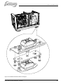
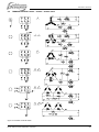
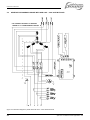
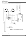
1
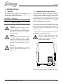
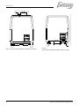
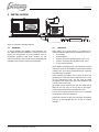
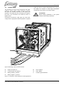
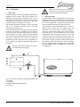
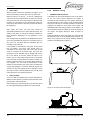
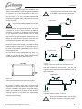
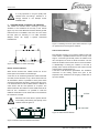
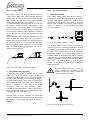
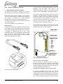
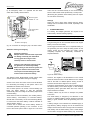
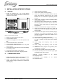
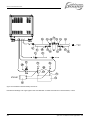
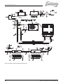
INSTALLATION MANUAL FOR MOBILE APPLICATIONS
W-SQ20
- 1500 RPM -
Mobile diesel generating set 230/400V / 50Hz
Digital Diesel Control
Art.nr. 40200616
WHISPER POWER BV
Kelvinlaan 82
9207 JB Drachten
The Netherlands
Tel.: +31-512-571550
Fax.: +31-512-571599
www.whisperpower.eu
V1 April 2010
CONTENTS
CONTENTS:
1
INTRODUCTION .............................................................................................................................................................. 3
1.1
General .............................................................................................................................................................. 3
1.2
Generating sets for vehicles ............................................................................................................................... 3
2
INSTALLATION ............................................................................................................................................................... 5
2.1
General .............................................................................................................................................................. 5
2.2
Location .............................................................................................................................................................. 5
2.3
Instructions for optimal sound and vibration insulation ....................................................................................... 6
2.3.1
Further recommendations ................................................................................................................. 6
2.4
Ventilation........................................................................................................................................................... 6
2.4.1
General.............................................................................................................................................. 6
2.5
Connections ....................................................................................................................................................... 7
2.5.1
Fuel supply ........................................................................................................................................ 8
2.5.2
Radiator cooling .............................................................................................................................. 10
2.5.3
Dry exhaust system ......................................................................................................................... 13
2.5.4
Electrical installation (12 Volt) ......................................................................................................... 15
2.5.5
AC power system (230 / 400 Volt) ................................................................................................... 17
3
INSTALLATION SPECIFICATIONS .............................................................................................................................. 19
3.1
General ............................................................................................................................................................ 19
3.2
Commissioning table ........................................................................................................................................ 19
3.3
Technical data .................................................................................................................................................. 20
3.4
Installation materials ......................................................................................................................................... 21
4
DIAGRAMS & DRAWINGS ........................................................................................................................................... 26
4.1
Layout generator control for W-SQ20 with 230VAC fan ................................................................................... 26
4.2
Terminal modes 115VAC – 230VAC - 400VAC 50Hz ...................................................................................... 27
4.3
Generator Diagram 3 phase with AVR 230V – 400V 50Hz with AVR............................................................... 28
4.4
AC Wiring Diagram single phase with AVR 230V Hz (Double Delta) ............................................................... 29
4.5
Electrical diagram radiator fan control 230VAC ................................................................................................ 30
4.6
Remote control panel drawings ........................................................................................................................ 31
4.7
W-SQ20 dimensions and footprint .................................................................................................................... 32
2
April 2010 / W-SQ20 for mobile applications / EN
CONTENTS
1 INTRODUCTION
1.1
GENERAL
This installation manual applies to the installation of the
Whisper Power W-SQ20 generator set in vehicles. This
manual is valid for the following models:
Part number
41101320
41101326
Description
W-SQ20 230V/400V 1500rpm Mobile
W-SQ20 230V/400V 1500rpm
Mobile -ungrounded
For other models see our website: www.whisperpower.eu.
WARNING
A warning symbol draws attention to special
warnings, instructions or procedures which, if
not strictly observed, may result in damage or
destruction of equipment, severe personal
injury or loss of life.
DANGER
This danger symbol refers to electric danger
and draws attention to special warnings,
instructions or procedures which, if not strictly
observed, may result in electrical shock which
will result in severe personal injury or loss of
life.
1.2
GENERATING SETS FOR VEHICLES
Whisper Generators originate from the marine sector. But
there are also specially designed Whispers available for
mobile applications, suitable for supplying power on board
of vehicles to use professional apparatus and equipment,
strong lightning and air conditioning etc. The cooling
system and exhaust system on vehicles is completely
different from standard marine systems.
On vehicles the engine of the W-SQ20 is cooled by a
radiator with an electric (230V or 3x400V) driven fan. Note
that the alternator of the W-SQ20 is cooled by air. The
radiator of the engine can be fitted below, on top or in the
side of the vehicle.
The exhaust is of the dry type and includes a stainless
flexible bellow and high quality mufflers.
Never use rubber exhaust hose, neither
fiberglass nor plastic exhaust parts in a dry
exhaust system as applied on vehicles.
Unless indicated otherwise.
WARNING!
Before working (installation) on the system
read the section safety instructions in the
user’s manual
Figure 1: Typical vehicle application radiator side mounted
EN/ W-SQ20 for mobile applications / April 2010
3
INTRODUCTION
Figure 2: Typical vehicle application radiator top mounted
4
Figure 3:
Typical vehicle application radiator bottom mounted
April 2010 / W-SQ20 for mobile applications / EN
INSTALLATION
2 INSTALLATION
Figure 4: Schematic installation diagram
2.1
GENERAL
To ensure reliability and durability of the equipment, it is
very important that the installation is carried out with the
utmost care and attention. To avoid problems, such as
temperature problems, noise levels, vibration, etc. the
instructions set out in this manual must be followed and all
installation work must be carried out professionally.
2.2
LOCATION
When looking for a proper place for a generator in a
vehicle all relevant aspects have to be taken into account
•
Accessibility
•
Solid foundation
•
Space to mount the radiators (Refer to par. 2.5.2)
•
Space to mount the exhaust (Refer to par. 2.5.3)
•
A way to fit the fuel lines
Since Whisper generating sets have extremely compact
dimensions, they can be installed in tight locations. Please
consider that even almost maintenance-free machinery
must still remain accessible.
When selecting the location area in which to mount the
generating set, make sure there is sufficient room to carry
out any maintenance work. The unit must be easily
accessible on the service side and on the distribution side
to have access to the V-belt.
All models can be serviced from one side. Note that oil
filling can be only done on the top side of the engine.
Cooling liquid can be filled via the expansion tank.
The top of the engine (rocker cover) has to be accessible
for adjustment of the valve clearance.
Please also note that in spite of the automatic oil pressure
sensor it is still essential that the oil level is checked
regularly.
EN/ W-SQ20 for mobile applications / April 2010
5
INSTALLATION
2.3
INSTRUCTIONS FOR OPTIMAL SOUND
AND VIBRATION INSULATION
Position the generating set as low as possible in the
vehicle. The generating set is already secured to the base
frame by means of flexible engine mountings. The base
frame is mounted to the chassis of the vehicle on a second
set of rubber mountings that is included in the delivery.
Use the included mounting template to determine the
mounting spots.
When it is possible to mount the unit directly on the
chassis of the vehicle this has advantages in preventing
vibrations by resonance.
2.3.1
Further recommendations
Whisper generating sets are standard equipped with a
sound cover. This sound cover has been designed to give
effective sound insulation. For optimum sound and
vibration dampening, the following factors should be
considered.
1
Most important is the structure on which the generator
is placed to be stiff. Directly below the rubber
mountings the structure should be supported vertically
to the chassis of the vehicle.
2
In larger vehicles a separate and insulated space for
the generator will help to damp the noise even further
3
Avoid mounting the generating set in close proximity
to thin walls or floors that may cause resonance.
4
Sound dampening is extremely poor if the generating
set is mounted on a light weight flimsy surface such
as plywood which will only amplify vibrations. If
mounting on a thinner surface cannot be avoided, this
should be at least be reinforced with stiffening struts
or ribbing. If possible, holes should be drilled or cut
through the surface to help reduce the resonance.
Covering the surrounding walls and floors with a
heavy coating plus foam will certainly improve the
situation.
5
Never connect the base of the generating set directly
to walls or tanks.
Figure 5: Mounting of the Whisper generating set.
6
2.4
2.4.1
VENTILATION
General
The generating set normally draws air from the engine
compartment. Engine compartments with natural
ventilation must have vent openings of adequate size and
location to enable the generating set to operate without
overheating. To allow an ample supply of air within the
temperature limits of the generating set an opening of at
2
least a half square meter (0,5 m ) is required.
A "sealed" engine compartment must have a good
extraction ventilator to maintain reasonable ambient
temperatures. High temperature of intake air reduces
engine performance and increases engine coolant
temperatures. Air temperatures above 25°C reduce the
engine power by 2% for each 5°C of rise. To minimise
these effects the engine room temperature must not be
more than 15ºC above the outside ambient air
temperature.
Apply a combination of ventilators, blowers and air intake
ducting to meet the temperature limit. The air inlet ducts
should run to the bottom of the engine compartment to
clear fumes from the bilge and to circulate fresh air. Air
outlets should be at the top of the engine compartment to
remove the hottest air. An engine compartment blower
should be used as an extraction ventilator to remove air
from the engine room.
In cases where it is impossible to meet the above
mentioned temperature limit by using engine compartment
ventilation, connections are to be made for an air inlet
directly to the generator enclosure. With these connections
the generating set can be directly connected to an air duct.
Air inlets should be louvered, where appropriate, to protect
the engine room and to protect the generating set from
rain and water spray.
X = wrong, V = OK
April 2010 / W-SQ20 for mobile applications / EN
INSTALLATION
2.5
CONNECTIONS
The generating set comes with all supply lines and output
cables (i.e. electric cables, coolant connections, exhaust,
fuel lines etc.) already connected to the engine and
generator. The supply lines are fed through the capsule’s
front base. The connections are marked as shown in
figures 7 till 10.
All electrical connections, cable types and sizes must
comply with the appropriate national regulations. Supplied
cables are rated for ambient temperatures up to 70°C. If
the cables are required to meet higher temperature
requirements, they must be run through conduits.
ATTENTION!
Before working (installation) on the system
read the section safety instructions
Figure 6: Mounting of the air strainer element
05
Exhaust connection 2”
09
Fuel out Ø8mm
06
Coolant Engine OUT Ø35mm
10
Fuel in Ø8mm
07
Battery positive (+) 35mm2
11
Coolant Engine IN Ø35mm
08
Battery negative (–) 35mm2
Figure 7: Connections of the W-SQ20 for mobile applications:
EN/ W-SQ20 for mobile applications / April 2010
7
INSTALLATION
2.5.1
Fuel supply
1 FUEL TANK
Fuel tanks should be made of appropriate material such as
(stainless) steel or plastic. Steel tanks should not be
galvanised or painted inside. Condensation can occur in
metal tanks when temperature changes. Therefore, water
accumulates at the bottom of the tank and provisions
should be made for the drainage of this water.
The tank will need a filling connection, a return connection
and an air ventilation connection which will require
protection against water entry.
Some official regulations do not allow connection points at
the base of the fuel tank; connections are to be made at
the top of the tank with internal tubing down to a few cm
above the bottom of the tank. Using the existing fuel tank
of the car-engine the fitting should be carried out with extra
care. Both a supply line and a return line should be
installed and go into the tank from the top. Interference of
the two systems (car engine and generator engine) should
be avoided.
Do NOT connect the fuel lines to the lines of
the vehicles engine fuel supply.
Driving the tank empty below the level of the
suction pipe of the generator could make it
necessary to bleed the fuel system.
2 FUEL LIFT PUMP
The generating set itself is equipped with a fuel lift pump;
therefore the tank can be installed at a lower level than the
generating set. See figure 8. The maximum suction height
is 1 m. The W-SQ20 has a mechanical fuel lift pump that
should be primed manually when the first time used.
If the pump has to lift the fuel higher than one meter an
external fuel lift pump must be installed. (Art. No.
50201060) The control board is already prepared to
connect an extra fuel pump. When using a second electric
fuel supply pump, it is recommended to mount a loose
supplied pump close to the tank and mount it in an angle
or vertical to prevent air bubbles to block the system. The
pump will become quite hot and should be mounted out of
touch. (Refer to figure 9) The pump makes clicking noises
and therefore could be mounted on rubber mountings.
When the clicking noises of the pump are not acceptable
an other noiseless pump is available as an option. (Art.
No. 50202200)
Figure 7 Fuel supply (fuel tank is above the generating set)
1 Fuel return
2 Fuel supply
3 Prefilter / Water separator (optional)
5 Fuel Tank
8
April 2010 / W-SQ20 for mobile applications / EN
INSTALLATION
1
2
5
A
3
4
Figure 8 Fuel supply (fuel tank is below the generating set)
1 Fuel return
2 Fuel supply
3 Prefilter / Water separator (optional)
4 Extra fuel lift pump (optional)
5 Fuel tank
Figure 9: Fuel line assembly with vertical mounted additional pump and fuel lift pump mounted in an angle
EN/ W-SQ20 for mobile applications / April 2010
9
INSTALLATION
3 FUEL PIPES
When the tank is above the generating set (figure 7) we
recommend ending the return line on the top of the tank.
When the return is on the top - in case of a leakage the
return line cannot overflow because of siphoning. One will
only need a fuel cock in the fuel supply line. When the tank
is below the generating set we recommend ending the
return line on the bottom of the tank (A) below the inlet of
the supply line.
Both supply and return fuel pipe lines should be
appropriate material and 8 mm outer diameter tubing. The
quality of the tubing of fuel pipes could be submitted to
local regulations depending on the application of the
vehicle.
The fuel pipes can be plumbed to the flexible hoses which
are on the generating set and have a connection to fit to 8
mm pipe. This fuel lines fulfils CE standards and are
according to ISO 7840 A2.
It is important to avoid bends in the pipes, as they could
trap air bubbles. The return pipe should never be
connected to the suction pipe. The return pipe should
never be connected to the suction pipe. The return line
should be of 8 mm diameter and go straight back via the
top to the bottom of the tank. When the return is too
narrow, has too many bents and goes back to the bottom
of the fuel tank, the back-pressure could be too high. This
results in irregular running of the engine. When the engine
runs irregular, one can check if back-pressure is the
problem by disconnecting the return line just outside the
canopy and draining it in a canister. When the engine runs
smooth now, the return piping has to be changed. It could
also help to install a second (electrical 12V) fuel lift pump
in the supply line to increase the pressure.
2.5.2
Radiator cooling
1 GENERAL INSTRUCTIONS
The radiator can be mounted below the floor, in the side or
on the roof of the vehicle. Wherever the radiator is
mounted the well functioning of the system depends on
the well circulation of the coolant. A roof mounted radiator
brings the most risk for circulation problems, because air
trapped in the radiator or a low level of the coolant, will
immediately affect the cooling capacity of the radiator. It is
recommended to keep the radiator as close as possible to
the engine. The piping should be fitted as direct as
possible.
When the radiator is above the engine, the piping should
be fitted below the top of the radiator! (refer to figure 10).
Bents in the piping, that can trap air bubbles, should be
avoided or ventilated (refer to figure 11)
Piping should not be fitted above the radiator!
OK
4 FUEL FILTERS
A fine fuel filter is installed which requires maintenance.
Whisper Power advises to install an extra fuel filter/ water
fuel separator near the fuel tank.
Before starting your generating set for the first time follow
the fuel system bleeding procedure in the users manual.
Figure 10: Air traps should be avoided
Figure 11: Ventilating an air trap
10
April 2010 / W-SQ20 for mobile applications / EN
INSTALLATION
Special attention should be paid to the ventilation of the
system. Each installation system is standard supplied with
an expansion tank for the coolant, which is also used to
release air bubbles and makes it possible to add coolant
into the system in an easy way. This expansion tank
should be at the highest point of the system and mounted
as high as possible.
The expansion tank must be fitted in the outlet
of the radiator = the inlet pipe of the engine
side mount
Most cooling problems originate from air traps
blocking the circulation of the engine coolant.
A
For the engine we use a pressurised system. The 12 mm
connection on the top is closed. Wherever the radiator is
mounted it is necessary to ventilate the exhaust manifold
of the engine. The exhaust manifold has an 8 mm
connection to ventilate the manifold. There is an 8 mm
high pressure and high temperature resistant hose in the
delivery to connect the hose connection on the side of the
manifold with the expansion tank. (refer to figure 6).
Initially the engine cooling system can be filled via the cap
on the exhaust manifold of the engine. However when the
radiator is above the engine one can only fill the system to
the level of the manifold. Additional filling has to be done
via the expansion tank.
For large engine cooling systems with long pipes or for
extra reserve there is an extra large expansion tank with a
content of 7 litres and an alarm for low coolant level that
can be supplied as an option (refer to figure 12).
bottom mount
Figure 13.
Outgoing connection connected to the expansion tank
When both radiators are flat mounted on the roof, the
expansion tanks should be mounted a little higher. (refer to
figure 14 detail B).
top mount
Figure 12:
7 litres optional expansion tank with low level alarm.
When mounting the radiator it is important to take care that
the outgoing connection, which is the connection to the
engine inlet, is on the top position (refer to figure 13 detail
A) and is connected to the expansion tank. Also when the
radiator is mounted flat at the bottom of the vehicle the
outgoing connection is connected to the expansion tank
This is the best way to have the system release air and to
add liquid when necessary.
EN/ W-SQ20 for mobile applications / April 2010
B
Figure 14:
Low profile radiator assembly on the roof
Most cooling problems originate from air traps
blocking the circulation of the engine coolant.
11
INSTALLATION
It is very important to use good quality heat
resistant hose and fittings. Therefore it is
strongly advised to use Whisper Power
installation kits.
2 HOW AND WHERE TO MOUNT THE RADIATOR
The radiator kit includes rubber mountings to prevent
vibrations to be transferred to the body of the vehicle
(figure 15). Due to the difference between vehicles general
instructions are not available. One has to find out where
the best place for mounting is. For OEM customers
Whisper Power can supply a special customised
installation kit.
Figure 17. Making use of the space below the floor to get
an optimal flow of air through the radiators.
Side mounted radiators
Figure 15. Radiator on rubber mountings
Bottom mounted radiators
When bottom mounted the radiator should not be the
lowest point of the vehicle to avoid damage.
A free flow of air should be guaranteed. When horizontal
mounted, the fan should be on top, which causes a flow of
air downwards. Often it is possible to find a place where
extra space above the fan helps to create a free flow of air.
It is recommended to make a shield below the radiator to
catch stones and dirt and operates as a spoiler. The
distance between the radiator and the shield should be at
least 50 mm. Sometimes it is possible to build the
radiators and shield on a sub frame that is mounted below
the vehicle as a module.
Most effective and easy is to mount the radiator in the side
of the vehicle, if possible below the level of the top of the
engine. A louvered grid should protect the radiator from
rain and objects, but must not block the airflow. The fan
should be inwards which causes the air to blow outwards.
A disadvantage of having the radiator in the side is
possibly more noise of the electric fan and a flow of air that
could be felt by people passing by.
A free flow of air should be guaranteed. The ventilation
connection of the cooling system that goes to the
expansion tank, should be in the outgoing coolant flow on
top of the radiator.
air flow
Measures have to be taken to prevent the hot
air circulating and reducing the capacity of the
radiators. Refer to figure 16
side mounted
Figure 18: Side mounted radiator
Figure 16: Bottom mounted radiators with shield
12
April 2010 / W-SQ20 for mobile applications / EN
INSTALLATION
Roof mounted radiators
2.5.3
The radiator on the roof is often the best option from the
point of view of keeping the noise of the fans away from
people and it will give the best result in dissipating the
heat. However, often this option conflicts with the possible
need to keep the vehicle as low as possible.
An other disadvantage is that the piping has to go through
the roof which requires provisions to be waterproof. Also
negative is that a roof mounted radiator is more sensitive
for air traps (see figure 10). When having enough space it
would be ideal to have the radiator vertically mounted on
the roof. Note that the expansion tank should be above the
radiator.
When having the radiator horizontally mounted on the roof
(refer to figure 19) enough space (50 mm) should be
between the roof and the radiator fan to have a free flow of
air. When the radiator is roof mounted there should be
protection against weather conditions. To avoid damage
while the vehicle is driving at high speed, the use of a
spoiler could be necessary.
1 GENERAL REMARKS
A dry exhaust muffler system should be very effective in
silencing the exhaust when applying the right mufflers.
However noise could be generated by vibrations in the
mufflers and be transferred to the chassis. Tacit factors
like the length of specific pipe sections could cause the
noise to be amplified. It is very difficult to take these
factors into account.
horizontal
vertical
Figure 19: Two examples of a top mount radiator
3 TWO SPEEDS FAN (OPTIONAL)
To keep the noise as low as possible the fan of the
radiator can run at two different speeds. As option a
control box is available which can be used to drive the fan
with two speeds, depending on the load of the generator.
In normal mode the electric motor of the fan is powered by
a low voltage and runs at low speed. This is achieved by
means of a transformer. In this mode the fan almost
produces no noise. Only when necessary - this is
controlled by thermostat switches - the fan is switched to a
higher voltage and will blow at full speed (refer to the
connection diagrams in paragraph 4.5).
Dry exhaust system
Figure 20: Dry exhaust systems on vehicles
The standard Whisper Power exhaust kit contains the
materials to perform a professional installation. In the kit is
a stainless steel flexible bellow (hose) to allow for
expansion and to prevent vibrations to be transferred.
Rubbers are supplied to mount the mufflers flexible. The
insulation blanket for the flexible bellow and the resonance
muffler are also very effective in damping vibrations. Still it
could be that additional measures has to be taken like an
extra clamp in a vibrating section of pipe, insulation
blankets on other parts of the system and possibly even
additional mufflers.
When the exhaust is led through the roof of a
vehicle, measures has to be taken to prevent
rainwater to enter the system. Special rain
caps are available as an option.
However, when not strictly necessary, we recommend
using the standard fan control instead of the two speeds
fan control, in order to keep the system as simple as
possible.
Figure 21. Ways to prevent water to get in
EN/ W-SQ20 for mobile applications / April 2010
13
INSTALLATION
A negative feature of a dry exhaust system is the heat
radiated by its components. Measures are taken to
overcome the heat problem: The exhaust bent to bring the
exhaust out of the canopy is cooled by water. Insulation
blankets are included in the exhaust kit to insulate the
flexible bellow and the first muffler.
When a dry exhaust has its outlet on the roof, all the pipes
inside the vehicle has to be insulated.
The exhaust pipes will be very hot and all
accessible pipes and mufflers are dangerous
to people when not insulated.
There are companies that are specialised in insulating hot
pipes and fancy systems are available to make it good
looking. However it is also possible to do it yourself by
winding fibreglass or Rockwool around the pipes and seal
it with aluminium tape.
2 THE STANDARD DRY EXHAUST SYSTEM
The standard exhaust system contains:
On the generator set:
•
An insulated exhaust bent
In the exhaust installation kit:
•
A stainless steel shielded flexible bellow.
•
One resonance muffler
•
One absorption muffler
•
Clamps and rubbers to mount the system flexible
•
Fittings, bents and pipes to make the different
connections
•
Blankets for thermal and sound insulation.
The mufflers are high quality industrial mufflers that are
much more effective, robust and durable than mufflers
made for automotive use.
3 INSTALLATION OF THE EXHAUST
Before determining the location of the generator set one
has to consider how to get away with the exhaust. Often
one can find space below the vehicle between the chassis
to mount the mufflers. The outlet should blow the fumes
away from the doors to avoid a nasty smell. When the
gasses are in the flow of air blowing from the radiators this
will help to avoid the fumes to be noticed. Under no
condition the fumes should be sucked into the flow of air
into the radiators. In wind still conditions a light smell of
exhaust fumes around the vehicle will not be avoidable.
To bring the exhaust to the top of the vehicle gives the
best results on noise and smell. However, when the pipes
go through the vehicle they should be insulated and
around the hole in the roof should be a collar to prevent
rainwater to leak in. Both mufflers could be on the roof or
one of them or both could be below the vehicle.
In general it is better to have the mufflers wide apart: the
resonance muffler close to the generator and the
absorption muffler on the end of the line. A short pipe
(30cm) should be on the far end after the absorption
muffler. The absorption muffler has no flow direction and
could be mounted both ways. The resonance muffler
should be mounted according to the indication on the
muffler itself.
The resonance muffler should be fitted
according to direction of the gas flow
indicated.
In the kit are clamps to mount the exhaust pipes to
stainless steel bars. These bars should be mounted to the
chassis of the vehicle. It is recommend to use rubber
mountings whenever possible. However take care that the
heat conducted through the brackets will not affect the
rubber. Refer to figure 22 how to mount the rubber in a
safe way. When any doubt an extra safe guard could be
constructed from steel wire or chain.
Figure 22: Mounting bracket in rubber with safe guard
14
April 2010 / W-SQ20 for mobile applications / EN
INSTALLATION
2.5.4
Electrical installation (12 Volt)
1 DIGITAL DIESEL CONTROL SYSTEM
The electrical control system is standard in 12 Volt with
negative earth. Non- earth return is available as an option.
All electrical wiring has been prepared on the generating
set to the control panel prior to despatch from the factory.
The engine is controlled by a very advanced
microprocessor based system: Digital Diesel Control.
The “black box” containing the microprocessor is located
on top of the alternator.
A local control panel is on the generating set.
Remote control
A remote control panel also containing a microprocessor is
in the delivery. A 15 m intermediate 8-pole communication
cable is in the standard supply as well (refer to figure 23).
If necessary an optional longer (up to 30m / 100ft)
intermediate cable can be connected if the standard length
does not suit the required distance. When a longer
distance than 30m / 100ft is required, consult the Whisper
Power service department for advice.
One can mount the control panel after drilling a hole in the
dashboard using the plastic cover. Refer to the
dimensional drawings in chapter 4. The panel without the
plastic cover fits the Mastervision modular panel system.
More remote control panels (slave panels) can be put in
parallel by using the modular connectors on the back of
the units. As a slave one can use the same panel offering
all functions again. It is also possible to use an old or new
type slave panel only to start and stop the generator.
Old type remote panels and system panels can be
connected by means of the green connector.
When using the factory settings, installation is very simple:
just plug the remote cable into the remote and the
generator is ready to use. Refer to figure 24.
REMOTE CABLE
REMOTE CABLE
12
11
10
9
8
7
J3
6
5
4
3
2
1
WIRING COLOURS
1
2
3
4
5
6
7
8
9
RED
GREEN
BROWN
YELLOW
PINK
PURPLE
BLUE
WHITE
RED/BLUE
10
11
12
GREY/PINK
GREY
BLACK
SENSE BAT. 2
WRP/2
WARNING RELAY
MAX. 150 mA
Whisper Remote Panel
Figure 24 Remote box terminals
Acoustic alarm or warning lamp
One can connect an external max.150 mA relay to
generate an acoustic warning or applying a warning lamp
etc. Be aware of polarity as some relays has a diode
inside and should be connected plus to plus en minus to
minus as indicated. Refer to figure. 24.
Connection for emergency stop / fire alarm switch
Figure 23 Remote control cable
EN/ W-SQ20 for mobile applications / April 2010
To connect an emergency stop button or to stop the
generator automatically in case of a fire alarm, you can
use the bypass connection between fastons J7 and J18 on
the backside of the local control panel. See figure 25. To
do so, remove this bypass connection and then replace it
15
INSTALLATION
by an emergency switch or a potential free fire alarm
switch with normally closed contacts
Remove bypass
between J7 - J18
local control panel
(rear view)
Normal operation
Alarm / emergency
Fig. 25: Connection for emergency stop / fire alarm switch
Automatic starting and stopping
Automatic start/stop
Whisper Power cannot be held responsible
for damage caused by the unattended
running generator using the autostart/stop mode or interval mode.
Using the auto-start/stop (interval) mode
the generator can start unexpectedly.
When working on the electrical system, the
3 Amp fuse must be removed from the
control panel and the battery plus cable
must be removed from the battery.
The Whisper Power Digital Diesel Control system offers
several options for automatic starting and stopping.
Access to this menu and other menus could be blocked.
For de-blocking and setting up this options refer to the
APPENDIX of the DDC user’s manual.
One of these options is to monitor a second battery (not
being the starter battery) to start the generator
automatically when the voltage of this battery drops below
a certain setting.
Other names for this second battery are “auxiliary battery”,
“service battery”, ”users battery” or “consumers battery”.
We will refer to this battery as “the second battery”(BAT2).
In some menus the starter battery could be indicated as
“the first battery” (BAT1).
A sense wire to monitor the second battery should be
connected (attention polarity!) to the connector on the
back of the remote panel. Refer to figure 24. The sense
16
wires must be connected directly on the second battery
before a main switch and be protected by a 3 Amps fuse.
(Monitoring the generator starter battery does not require
an extra sense connection)
Settings
When one want to apply other settings than the factory
settings refer to the DDC users manual, especially to the
APPENDIX.
2 STARTER BATTERY
For starting, the Whisper generator set requires a 12V
starter battery with the following capacity:
Model
W-SQ20
Minimum capacity
120Ah
The generating set can be connected with the main engine
battery or have its own battery.
We strongly recommend the use of a separate battery for
the generating set and to keep the wiring system for the
vehicle engine and the domestic DC supply system
completely separate and individually connected to
separate batteries.
230VAC
IVO 12/10
A
B
+
12V
-
Figure 26 Starter battery
However, the negative of all the batteries on the vehicle
should be interconnected to avoid difference in the voltage
level of the earth on different places causing trouble to
electronic devices which might be in the system.
The above recommendation is not valid for vehicles having
the starter battery of the vehicle engine or other auxiliary
equipment positive grounded. When this is the case an
expert should be consulted.
A battery switch may be used to interrupt the positive
connection.
The starter battery is charged by the alternator on the
engine. An additional battery charger will help to keep the
battery in good condition when the generating set is not
used.
A battery charger is not included in the standard supply. A
high efficiency battery charging unit can be ordered from
Whisper Power which is able to charge both the vehicles’s
main battery and the starter battery. Also a small charger
can be used to charge the starter battery only, such as the
April 2010 / W-SQ20 for mobile applications / EN
INSTALLATION
IVO SMART 12/10. A battery switch and a charger are
included in the battery installation kits, art. no. 40230220
(160Ah)
3 OTHER RECOMMENDATIONS AND WARNINGS
The battery should be secured for poor road conditions
and the terminals should be insulated. For extra safety the
battery can be enclosed in a wooden, plastic, fiberglas etc.
(non metal) box. Even when the earth return system is
applied a negative battery cable should be used and the
vehicle should not to be used as a conductor.
The battery cables are supplied in a standard length of 1.5
m, if longer cables are required a larger cross sectional
area should be considered to compensate for voltage
reduction.
When two batteries are used in series to
provide a 24 Volt supply system, never take
off 12 Volt (starting) power from one of these
batteries. This will result in severe damage to
both batteries within a short time.
Disconnect the battery leads if electrical welding is to be
carried out, otherwise damage will be caused to the diodes
of the alternator.
As explosive hydrogen gases may be
discharged during charging, the battery
should be located in a well ventilated room.
Ensure that the supplied battery cable
connectors are properly fitted and never
remove during or shortly after charging as
sparking can occur, which may ignite the
hydrogen gasses.
2.5.5
AC power system (230 / 400 Volt)
The electric power supplied by the generator
is of a high voltage and dangerous to people.
Before working (installation) on the system
read the sections on safety in the users
manual.
Realise hat people are not used to have
230/400 Volt available on a vehicle. Put
warning signs on wall sockets and on junction
boxes. Instruct non-regular users of the
vehicle. Warn maintenance personal of
garages that do service on the vehicle.
Generators used on vehicles that are
operated in a hazardous environment have
often to fulfill special regulations and
additional measures have to be taken
accordingly.
Be sure that all electrical installations (including all safety
systems) comply with all required regulations of the local
authorities. All electrical safety/shutdown and circuit
breaking systems have to be installed onboard as the
generating set itself cannot be equipped with such
equipment for every possible variation.
The vehicle’s power supply system should be suitable and
safe for the AC voltage which is applied and the power
that will be generated. Special attention has to be paid on
dividing the system in branches which are fused
individually.
It is absolutely essential that each and every circuit in the
electrical system is properly installed by a qualified
electrician.
The W-SQ20 can be connected as a single phase 230 Volt
generator by an arrangement of the wiring in double
DELTA. When the wires are arranged in STAR the output
will be 230/400Volt.
Connected as a three phase 230/400 Volt generator, 3x
400 Volt is available between the phases. At the same
time 230 Volt is available between every phase and
neutral.
When applying 3 phases the installation should be laid out
in such a way that there is a reasonable balance of load
between the three phases.
To avoid problems with unbalanced loads one could apply
a 400V 3 phase to 230 Volt single phase transformer.
EN/ W-SQ20 for mobile applications / April 2010
17
INSTALLATION
1 FUSE
An output fuse (between the generating set and the
electrical installation) should be installed to protect the
installed electrical system.
For the W-SQ20 the maximum single phase current at
230V is 108 Amps. Using three phases the fuses should
be three times 36 Amps and mechanically connected. The
fuses must be of the slow reacting type. For electrical
motors connected to the system, a motor protection switch
must be installed
2 GROUNDING
The AC alternator windings are not grounded.
The housing of the alternator and all other metal parts are
grounded
To make a connection between “neutral” and “ground” is
necessary as part of a specific insulation failure protection
system.
It is possible that the electric installation in the vehicle
must be protected against insulation failures. Methods of
protection are subjected to rules that can be different
depending on the use of the vehicle and local standards.
Experts in this field should be consulted
18
3 CABLE
For the power cable we recommend the use of 3 wire
single phase or 5 wire tri-phase oil resistant cable with a
sufficient cross sectional area. One wire for earth is
included. For long cables it is recommended to apply
cables with a larger cross section (refer to ISO 13297
annex A)
4 TRANSFER SWITCH
A power source selector switch much be installed between
the generating set and the vehicle’s electrical supply
system. This switch must ensure that all AC consumers
can be switched off at once. This switch should also be
installed to keep the generating set and shore (grid) power
systems separate.
Transfer switches - to switch over from a land line to
vehicle or from generating set to inverter - should be well
designed to switch over all wires including neutral (and not
only phases or line) and there should be provisions with
the aid of timers to prevent relays from clattering.
April 2010 / W-SQ20 for mobile applications / EN
INSTALLATION SPECIFICATIONS
3 INSTALLATION SPECIFICATIONS
3.1
1
GENERAL
Install the generating set on the 4 anti vibration
mounts. Use the template included in the shipment to
drill the 8 mounting holes.
3
4
5
6
7
8
9
ANTIVIBRATION
MOUNTS
10
Figure 27: Anti-vibration mounts
2
3
4
Mount the cooling system for the engine
Connect exhaust system.
Connect ‘fuel supply line’ to the water separator/ fuel
filter.
5 Connect ‘fuel return line’ to the fuel tank.
6 Connect remote panel (just plug in).
7 Connect the AC cable from the AC box to the power
source selector.
8 Connect plus and minus from the 12V starter battery
to the battery cables.
9 Connect the power supply of the radiators
10 Install a Whisper Power battery charger (optional).
3.2
1
2
COMMISSIONING TABLE
Check if the cooling system for the engine is properly
installed. Note that air traps must be avoided.
Check if the exhaust system is properly installed.
Check maximum length of exhaust hose, diameter of
exhaust piping.
EN/ W-SQ20 for mobile applications / April 2010
11
12
13
14
15
16
17
Check all coolant connections.
Check the AC cables and the grounding.
Check if an AC breaker is installed before or after the
power source selector. When there is only a circuit
breaker, use it to disconnect the generating set from
the grid.
Check all DC connections, check if the battery switch/
circuit breaker is closed.
Open the fuel valve. Check if there are no air leaks in
the fuel supply line, and check if the lift of the fuel is
less than 1 meter. Check if there is no air in the water
fuel separator.
Check if the air intake in the canopy is not blocked.
Check the oil level and colour of the oil. Check the
coolant level of both the alternator cooling and the
engine cooling.
To bleed the fuel system use the manual pump by
turning the cap loose and pumping as long as
necessary to bleed the system. See chapter 4.2.2 of
the user’s manual.
Start the engine by pushing the start button
Check when the generating set is running, the delay
of 5 to 10 seconds in the power source selector
transfer.
Check voltage and frequency under ‘no load’
conditions.
Check voltage and frequency under ‘full load’
conditions.
Check if the battery charger of the generating set is
working (max. 14.5 Volt).
Close the sound shield and check the noise level.
Stop the generating set and check the engine again
for leakages of oil, fuel or coolant.
Installation checklist
www.whisperpower.eu.
Commissioning form
www.whisperpower.eu.
available
on
our
website:
available
on
our
website:
19
INSTALLATION SPECIFICATIONS
3.3
TECHNICAL DATA
W-SQ20
Dimensions incl. sound shield.
126 x 68 x 80 cm (L x W x H)
Dimensions w/o. sound shield.
115 x 60 x 75 cm (L x W x H)
Weight incl. sound shield
580 kg
Weight w/o. sound shield
480 kg
Max. operation angle
25°
Remote panel 15 m cable
Digital Diesel Control System
Battery capacity min.
120 Ah
Fuel consumption
1 – 6 l/hr, load dependent
Lift fuel pump
Mechanical driven; manually priming
Max lift fuel pump
1m
Cooling
Radiator cooling
Minimum water supply
20-25 l/min
Alternator
synchronous brushless, maintenance free, air cooled
Voltage regulation
AVR
Output power at power factor cos phi = 1 25kW*, 230V or 230/400V 50Hz
Battery charger
alternator including regulator (50 Amps)
* Note that this value must be reduced by the power to drive the cooling fans of the radiators.
20
April 2010 / W-SQ20 for mobile applications / EN
INSTALLATION SPECIFICATIONS
3.4
INSTALLATION MATERIALS
BATTERY INSTALLATION KIT 160 Ah
no
qty
article no
description
51
1
42001600
Whisper Power AGM Battery 12V/160Ah
52
1
43011000
battery charger IVO SMART 12/10
53
1
48060100
battery terminal +
54
1
48060200
battery terminal –
55
1
48456902
isolation cap
56
1
48456914
isolation cap
57
1
49009005
battery switch
58
4
4503003508
cable connectors
TOTAL
40230220
BATTERY INSTALLATION KIT 160 Ah
FUEL KIT
no
41
42
43
44
45
46
47
48
49
TOTAL
qty
2
1
2
2
2
2
1
4
2
article no
50221203
50230090
50221618
50221644
50221615
50221616
50221252
50221522
50221632
40230205
description
Straight coupling
Fuel strainer/water separator
Parallel male stud coupling
Reducing male nipple
Hose connection
Nut coupling
Nipple hose pipe
Hose clamps
Gasket ring
FUEL KIT
OPTIONAL INSTALLATION MATERIALS
no
qty
article no
description
50
1
50222020
copper fuel pipe
51
1
50220063
fuel hose
EN/ W-SQ20 for mobile applications / April 2010
dimensions
160Ah
M8
M8
250 Amp
M8x35
dimensions
8 mm
M14x1.5 mm
M14 - 8 mm
M14-M16 60 gr.
8 mm
M16x1.5 mm
8 mm
10-16 mm
14x20x1.5 mm
dimensions
6x8 mm
8x16 mm
21
INSTALLATION SPECIFICATIONS
Figure 28. Installation materials battery and fuel kit
Included are all fittings to fit copper pipes 8 mm outer diameter or rubber fuel hoses 8 mm inner diameter, or both
22
April 2010 / W-SQ20 for mobile applications / EN
INSTALLATION SPECIFICATIONS
RADIATOR COOLER KIT ENGINE 230VAC W-SQ20
no
qty
article no
description
1
1
50230511
Radiator AP 130EB 230 VAC
2
2
50221502
Hose clamp stainless 22-30
3
1
50221064
“Male nipple 1”
4
1
50221044
TEE-fitting-1”
5
2
50221014
Male hose connection 1”x35
6
1
50221103
“Straight reducer m/f 1”-3/4”
7
1
50221004
Male hose connection 3/4x20
8
1
50212409
Temperature switch 87-82 degr
14
6m
50220013
Cooling water hose smooth (1 1/4”) 32x41mm
15
4
50221504
Hose clamp stainless 35-50mm
16
8
50221597
Hose support SP 45x20 mm galvanised
17
1
50230529
Bracket expansion tank for 50230531
17
1
50230531
Expansion tank 20 mm
17
1
50230532
Cap tank 0502 30531
18
1.5m 50220011
Cooling water hose smooth (3/4”) 18x27mm
19
2
50221142
Straight reducer m/f 1½”-1”
20
4m
50220005
Hose hydraulic 7.5x15mm
21
2
50221522
Hose clamp stainless 10-16mm
TOTAL
40201897
Radiator cooler kit engine 230VAC W-SQ20
RADIATOR COOLER KIT ENGINE 3x400VAC W-SQ20, Same as article no. 40201897, except:
no
qty
article no
description
1
1
50230512
Radiator AP 130EB 3x400 VAC
TOTAL
40201898
Radiator cooling kit engine 3x400VAC W-SQ20
OPTIONAL INSTALLATION MATERIALS
no
qty
article no
description
22
1
50230535
Expansion tank 7L + low level alarm switch
DRY EXHAUST KIT 2” for W-SQ20
no
qty
article no
61
1
50220067
62
1
50220042
63
1
50230574
description
Exhaust hose SS 500mm fem./male 2”
Insulation blanket 42x26 exhaust hose 2”
Absorption muffler steel 2”
64
65
66
67
68
69
70
71
72
73
75
76
77
78
TOTAL
Resonance muffler steel 2”
Insulation blanket muffler HD 2”
“Pipe nipple 2”x300mm galvanised”
Parallel male coupling 11/2” galvanised
Straigt coupling f/f 2”galvanised
U-clamp 73 mm M10
Bracket U-clamp 25cm 48-60mm passivated
Washer SP M10
Washer spring SP M10
Nut hexogonal SP M10
Elbow 90 degr m/f gavalvanised 2”
End cover insulation blanket HD 2”
Insulation blanket muffler SDHD 2”
End cover insulation blanket SDHD 2”
DRY EXHAUST KIT 2” for W-SQ20
1
1
2
2
2
3
3
6
6
6
1
2
1
2
50230575
50230576
50221404
50221424
50221414
50221668
50221664
50211406
50211448
50211466
50221476
50230577
50230578
50230579
40201889
EN/ W-SQ20 for mobile applications / April 2010
23
INSTALLATION SPECIFICATIONS
Figure 29: radiator cooling kit engine and exhaust kit
24
April 2010 / W-SQ20 for mobile applications / EN
INSTALLATION SPECIFICATIONS
Figure 30: Installation materials rubber mounting kit
EN/ W-SQ20 for mobile applications / April 2010
25
DIAGRAMS & DRAWINGS
4 DIAGRAMS & DRAWINGS
LAYOUT GENERATOR CONTROL FOR W-SQ20 WITH 230VAC FAN
Optional control for two speeds fans.
See chapter 4.5
4.1
Figure 31: Layout generator control for W-SQ20 230VAC radiator fan
26
April 2010 / W-SQ20 for mobile applications / EN
DIAGRAMS & DRAWINGS
4.2
TERMINAL MODES 115VAC – 230VAC - 400VAC 50HZ
Figure 32 Terminal modes W-SQ20
EN/ W-SQ20 for mobile applications / April 2010
27
DIAGRAMS & DRAWINGS
4.3
GENERATOR DIAGRAM 3 PHASE WITH AVR 230V – 400V 50HZ WITH AVR
* TO
CONNECT
NEUTRAL
TO GROUND
* TO
CONNECT
NEUTRAL
TO GROUND
REFER
2.1.3
USER
MANUAL
W-SQ2025U
REFER
TOTO
2.1.3
USER
MANUAL
WHISPER
*
Figure 33: Generator Diagram 3 phase with AVR 230V – 400V 50Hz with AVR
28
April 2010 / W-SQ20 for mobile applications / EN
DIAGRAMS & DRAWINGS
4.4
AC WIRING DIAGRAM SINGLE PHASE WITH AVR 230V HZ (DOUBLE DELTA)
* TO CONNECT NEUTRAL TO GROUND
*REFER
TO CONNECT
NEUTRAL TO GROUND
TO 2.1.3 USER MANUAL W-SQ20
REFER TO 2.1.3 USER MANUAL WHISPER 25U
Figure 34: AC Wiring Diagram single phase with AVR 230V Hz (Double Delta)
EN/ W-SQ20 for mobile applications / April 2010
29
DIAGRAMS & DRAWINGS
4.5
ELECTRICAL DIAGRAM RADIATOR FAN CONTROL 230VAC
Fig. 35: Electrical diagram for standard fan control
using a 230V AC radiator fan
JUNCTION BOX AIR FANS
TRAFO
230/115VAC
200VA
12VDC
K1
K2
230VAC
DIMENTION BOX: 270x270x180 MM
Fig. 36: Electrical diagram fan control using a 230V
AC radiator fan – with two speeds fans (optional)
30
April 2010 / W-SQ20 for mobile applications / EN
DIAGRAMS & DRAWINGS
4.6
REMOTE CONTROL PANEL DRAWINGS
Fig. 37: Whisper remote panel
The remote panel comes in a carton that can be used as a template to drill the mounting hole
EN/ W-SQ20 for mobile applications / April 2010
31
DIAGRAMS & DRAWINGS
4.7
W-SQ20 DIMENSIONS AND FOOTPRINT
Fig. 38 W-SQ20 dimensions and footprint
CONNECTIONS W-SQ20:
• exhaust:
2”
• fuel hose:
8 mm
• coolant in/out:
Ø 35 mm
• battery +:
35 mm2
• battery -:
35 mm2
POWERCABLES
• W-SQ20 230V
single phase (108 Amps)
3x25 mm2 (not included)
• W-SQ20 230/400V
3 phases (3x 36Amps)
5x6 mm2 (not included)
REMOTE CABLE (ALL MODELS)
• 8 wire communication cable, 15 meter (included).
For longer lengths (max. 30 m), refer to Whisper Power service department
DIMENSIONS W-SQ20
• length
• width
• height
• weight
32
Incl. sound canopy
126 cm
68 cm
80 cm
580 kg
Without sound canopy
115 cm
60 cm
75 cm
480 kg
April 2010 / W-SQ20 for mobile applications / EN
NOTES
NOTES:
EN/ W-SQ20 for mobile applications / April 2010
33
NOTES
NOTES:
34
April 2010 / W-SQ20 for mobile applications / EN
NOTES
NOTES:
EN/ W-SQ20 for mobile applications / April 2010
35
Kelvinlaan 82, 9207 JB Drachten, The Netherlands
Tel : + 31-512-571550 / Fax : + 31-512-571599
www.whisperpower.eu / [email protected]